1
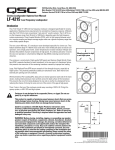
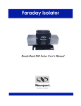
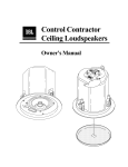
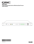
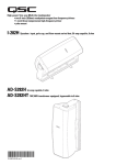
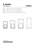
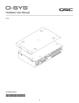
AD-C Series
AD-C820/AD-C821/ AD-C1200 User Manual
AD-C820 – 203 mm (8") 2-way coax baffle assembly
AD-C800BB – Pre-install enclosure for AD-C820
AD-C821 – 203 mm (8") 2-way coax blind-mount
AD-C800 RAIL KIT – Split Ring and Tile Rails for AD-C821
AD-C800RG – Round Grille for 8" loudspeaker
AD-C800SG – Square Grille for 8" loudspeaker
AD-C1200 – 304 mm (12") 2-way coax baffle assembly
AD-C1200BB – Pre-install enclosure for AD-C1200
AD-C1200SG – Square Grille for 12" loudspeaker
TD-000296-00 REV. C
*TD-000296-00*
IMPORTANT SAFETY PRECAUTIONS AND EXPLANATION OF SYMBOLS
WARNING!
1. Read these instructions.
2. Keep these instructions.
3. Heed all warnings.
4. Follow all instructions.
5. Clean only with a dry cloth.
6. Install in accordance with QSC Audio Product’s instructions and local building codes. The installation should be done by a licensed
installation professional.
7. Do not install near any heat sources such as radiators, heat registers, stoves, or other apparatus (including amplifiers) that produce heat.
8. Only use attachments/accessories from QSC Audio Products, LLC.
9. Use only with mounts or brackets supplied or specified by QSC Audio Products, LLC.
10. Refer all servicing to qualified personnel. Servicing is required when the apparatus has been damaged in any way.
The lightning flash with arrowhead symbol within an equilateral triangle is intended to alert the user to the presence of un-insulated
“dangerous” voltage within the product’s enclosure that may be of sufficient magnitude to constitute a risk of electric shock to humans.
The exclamation point within an equilateral triangle is intended to alert the user to the presence of important operating and maintenance
(servicing) instructions in this manual.
WARNING! Before placing, installing, rigging, or suspending any speaker product, inspect all hardware, suspension, cabinets,
transducers, brackets and associated equipment for damage. Any missing, corroded, deformed or non-load rated component
could significantly reduce the strength of the installation, placement, or array. Any such condition severely reduces the safety of the
installation and should be immediately corrected. Use only hardware which is rated for the loading conditions of the installation
and any possible short-term unexpected overloading. Never exceed the rating of the hardware or equipment. Consult a licensed,
professional engineer when any doubt or questions arise regarding a physical equipment installation.
Warranty (USA only; other countries, see your dealer or distributor)
Disclaimer
QSC Audio Products, LLC is not liable for any damage to amplifiers, or any other equipment that is caused by negligence or improper installation and/
or use of this loudspeaker product.
QSC Audio Products 3-Year Limited Warranty
QSC Audio Products, LLC (“QSC”) guarantees its products to be free from defective material and / or workmanship for a period of three (3) years from
date of sale, and will replace defective parts and repair malfunctioning products under this warranty when the defect occurs under normal installation and
use - provided the unit is returned to our factory or one of our authorized service stations via prepaid transportation with a copy of proof of purchase (i.e.,
sales receipt). This warranty provides that the examination of the return product must indicate, in our judgment, a manufacturing defect. This warranty
does not extend to any product which has been subjected to misuse, neglect, accident, improper installation, or where the date code has been removed
or defaced. QSC shall not be liable for incidental and/or consequential damages. This warranty gives you specific legal rights. This limited warranty is
freely transferable during the term of the warranty period. Customer may have additional rights, which vary from state to state.
In the event that this product was manufactured for export and sale outside of the United States or its territories, then this limited warranty shall not apply.
Removal of the serial number on this product, or purchase of this product from an unauthorized dealer, will void this limited warranty.
Periodically, this warranty is updated. To obtain the most recent version of QSC’s warranty statement, please visit www.qscaudio.com.
Contact us at 800-854-4079 or visit our web site at www.qscaudio.com.
© Copyright 2010, QSC Audio Products, LLC
QSC® is a registered trademark of QSC Audio Products, LLC
“QSC” and the QSC logo are registered with the U.S. Patent and Trademark Office
All trademarks are the property of their respective owners.
1
Introduction
Congratulations and thank you for your ceiling loudspeaker purchase. The AD-C820, AD-C821 and AD-C1200 models offer excellent acoustic
performance in an easy-to-install and attractive package. Please review these instructions carefully and follow the recommendations.
Installation should be done by a licensed installation professional and in accordance with these instructions and local building codes.
The AD-C820 and AD-C821 models feature an 8" coaxial driver with a high-frequency neodymium compression driver and low-frequency ferrite
woofer in a ported baffle assembly. The AD-C1200 model features a 12" coaxial driver with a 1.75" compression driver and a 12" low-frequency ferrite
woofer in a ported baffle assembly.
All models are equipped with an audio transformer suitable for 70V and 100V distributed loudspeaker systems. The AD-C820 and AD-C821
are equipped with a 6 position tap selector switch which has an Off position and can bypass the transformer for 16 ohm applications. On the
AD-C1200 tap selection is accomplished using terminal block connectors during installation. There is also a connection for bypassing the transformer
for 16 ohm operation.
Package Contents
AD-C1200
AD-C820
Loudspeaker Baffle — 1 component
AD-C820 Loudspeaker Baffle — 1 component
User Manual — 1 component
User Manual — 1 component
Product Warranty Card — 1 component
Product Warranty Card — 1 component
Mounting Screws (size M5) — 6 components
AD-C800BB
AD-C1200BB
Back Box Assembly — 1 component
Back Box Assembly — 1 component
Instruction Sheet — 1 component
Instruction Sheet — 1 component
AD-C1200SG
AD-C800RG/SG
Grille Assembly — 1 component
Grille Assembly — 1 component
Instruction Sheet — 1 component
Instruction Sheet — 1 component
Spare Grille Cloth — 1 component
Spare Grille Cloth — 1 component
M4 x 30mm Screws — 4 components
Screw-hole Template — 1 component
M4 Plastite® Screws — 4 components
AD-C821
Loudspeaker System — 1 component
AD-C800 RAIL KIT
User Manual — 1 component
Split Rings — 1 components
Product Warranty Card — 1 component
Suspended-ceiling Tile Rails — 2 components
Mounting Hole Template — 1 component
M4 Sheet Metal Screws — 2 components
2
Features
AD-C821 Loudspeaker System
d
c
e
b
a
– Figure 1 –
f
g
h
– Figure 2 –
a. Pivoting connection cover
b. Euro connectors
c. Pivoting connection cover retaining screw
d. Loudspeaker wiring hole
e. Seismic mounting tab
f. Mounting tabs
g. Grille attachment magnets
h. Tap switch (transformer included)
3
AD-C820 Loudspeaker Baffle
a
b
c
a. Mounting tabs
– Figure 3 –
b. Grille attachment magnets
c. Tap Switch (transformer included in AD-C800BB)
AD-C800BB Back Box
Sold separately for use with AD-C820 Loudspeaker Baffle
a
a
b
a
c
e
a
d
a
a. Dual Knockouts (½" and ¾") (Qty: 5)
– Figure 4 –
b. Ceramic terminal block
c. Transformer
d. Mounting straps (Qty: 4)
e. Ten-pin Mate-N-Lok™
4
AD-C800 Rail Kit
The AD-C800 RAIL KIT is sold separately for use with the AD-C821 loudspeaker system.
– Figure 5 –
– Figure 6 –
Split Ring
Suspended-ceiling Tile Rail
AD-C800SG/RG Loudspeaker Grilles
Sold separately for use with the AD-C820 and AD-C821 loudspeaker systems
– Figure 7 –
– Figure 8 –
AD-C800RG
AD-C800SG
5
AD-C1200 Loudspeaker Baffle
a
c
b
d
– Figure 9 –
a. Dual Euro connectors
b. 150 W Transformer for 70/100 V distributed loudspeaker systems
c. Crossover network
d. Installation hook
AD-C1200BB Back Box
Sold separately for use with AD-C1200 Loudspeaker Baffle
b
a
a
a
a
c
a
– Figure 10 –
a. Dual knockouts (½" and ¾") (Qty: 5)
b. Mounting tabs (Qty: 4)
c. Ceramic terminal block
6
AD-C1200SG Loudspeaker Grille
– Figure 11 –
AD-C821 Installation Options
The AD-C821 Loudspeaker System is a blind-mount design made to mount into finished ceilings. The AD-C821 loudspeaker system can be mounted
in suspended ceilings, as well as non-suspended ceiling types. We recommend that you consult an installation professional for safety assurance,
quality installation, and optimum acoustic performance.
Suspended Ceiling
The Suspended-ceiling Tile Rails (Figure 6) must be used with the Split Ring bracket (Figure 5). The Suspended-ceiling Tile Rails are designed to be
used with 24" (600 mm) t-channel suspended-ceiling supports to provide necessary strength for mounting.
Non-suspended Ceilings
For other ceiling types, the Split Ring bracket is used to reinforce the mounting surface.
Safety Features
The AD-C821 provides two safety features: a Seismic Mounting Tab and a Grille-retaining Safety Tether.
• The Seismic Mounting Tab is the metal tab, on top of the enclosure, suitable for securing the loudspeaker system to building framing. This provides
maximum safety in the event the ceiling structure fails for any reason.
• The Grille-retaining Safety Tether is comprised of two plastic lines, one coming from the grille, the other from the loudspeaker assembly, that hook
together to prevent the grille from falling.
7
AD-C821 Installation
Tools and Parts Required for Installation
1. #2 Phillips head screwdriver
2. Torque driver
3. Wire stripping tool
4. Soldering equipment
5. Tool for cutting loudspeaker mounting hole in ceiling. Must be able to cut a circular hole through the ceiling without damaging the structural
integrity of the ceiling.
6. Small flat-tip screwdriver for securing wires in Euro-style connector.
7. Wire Clamp Fitting to install in the cover plate loudspeaker wiring hole to protect and stabilize the loudspeaker wires. This can be a standard
electrical conduit wire clamp, or something similar. The hole is 1.1" ( 28.3 mm).
8. Cable for Seismic Support bracket. The cable must be:
a. Strong enough to support ten times the weight of the loudspeaker (15 lbs / 6.8 kg). Consult local building code requirements.
b. Long enough to reach from a structural part of the building, such as a beam, to just below the ceiling to provide enough room to attach it
to the Seismic Support bracket, prior to installing the loudspeaker.
c. Made of material that does not burn and is not easily cut. For example, a steel cable.
9. Fastener for attaching seismic support cable to a structural support of the building. The fastener must be strong enough to hold ten times the
weight of the loudspeaker system. Consult local building code requirements.
Installation
There are two methods for installing the AD-C821 loudspeaker system into the ceiling: using the Mounting Clamps with or without the Split Ring or
using the Suspended-ceiling Tile Rails with the Split Ring.
• The Split Ring with Suspended-ceiling Tile Rails is recommended for suspended ceilings with 24" (600 mm) wide panels. The support brackets,
along with the ceiling cross-supports, provide necessary support.
• The Mounting Clamps, with or without the Split Ring, are recommended for non-suspended ceilings that can support the weight of the AD-C821
Loudspeaker System without additional support.
Cut Mounting Hole in Ceiling
The following steps are for any of the AD-C821 installation methods except where noted.
1. Make sure there is at least 12" (305 mm) clearance above the suspended ceiling at the spot where the AD-C821 is to be installed.
2. Use the outer edge of the Mounting Hole Template or the Split Ring inner edge as a pattern to mark the suspended-ceiling panel for the mounting
hole cutout. If you are not using Mounting Hole Template or Split Ring, the hole diameter should be 11.7" (297 mm).
3. Use a suitable tool to cut the mounting hole in the suspended-ceiling panel. While cutting the hole, be sure not to stress the mounting surface to
prevent cracking and weakening the structural integrity.
4. Insert the AD-C821 into the mounting hole to make sure the loudspeaker system fits properly. Remove the loudspeaker system.
5. Pull the facility’s loudspeaker signal wires through the mounting hole.
8
15.16"
395 mm
– Figure 12 –
Install Split Ring and Suspended-ceiling Tile Rails
1. Skip this step if installing in a non-suspended ceiling. Pass the two Suspended-ceiling Tile Rails (Figure 6) through the hole and place on both sides
of the mounting hole 15.16" (395 mm) apart, as shown in (Figure 12) and install onto the ceiling T-rails. Make sure the bottom part of the bracket
(that is flat against the tile) is toward the mounting hole and the vertical rail of the support bracket (with the holes in it) is away from the mounting
hole (Figure 13).
Note: The support brackets have holes along their usable length to attach the Split Ring bracket (Figure 13). This allows for the mounting hole
to be placed in many positions along the ceiling tile width.
2. Insert the Split Ring through the mounting hole by slightly bending the ring apart at the split, inserting one end through the mounting hole, and
rotating or “screwing” the ring through the hole.
3. Skip this step if installing in a non-suspended ceiling. Install the Split Ring onto the Suspended-ceiling Tile Rails by placing the vertical slots on the
Split Ring over the vertical rail of the support bracket. Move the Split Ring as necessary to align it with the mounting hole (Figure 13) and a hole in
each support bracket.
4. Skip this step if installing in a non-suspended ceiling. Use two of the M4 sheet metal screws provided in the AD-C800 RAIL KIT to attach the Split
Ring to the Suspended-ceiling Tile Rails.
– Figure 13 –
9
Support and Wire the Loudspeaker System
Important: Loudspeakers can potentially generate substantial vibration. In addition to ensuring all hardware is properly installed and secure,
you must use the Seismic Support Bracket on the loudspeaker to secure the loudspeaker to an appropriate structural support. This minimizes
the chance of the loudspeaker falling from the ceiling in the event the primary mount fails. Any cable or wire used as a secondary support
line must be strong enough to support ten times the weight of the loudspeaker system. Do not use rope, string, twine or other textile-based
line in the Seismic Support system as it is easily cut or burned. The Seismic Support attachment point and any fasteners used on the building’s
structure must also be strong enough to support ten times the weight of the loudspeaker.
1. Using an appropriate fastener, attach the seismic support cable to a structural support of the building such as a beam.
2. Attach the loose end of the cable to the Seismic Support bracket on the loudspeaker system so that it is supported slightly below the ceiling. (This
should allow enough room to install the loudspeaker wiring as described in the following steps.)
3. Use a #1 Phillips head screwdriver to loosen the Pivoting Connection Cover Retaining Screw (Figure 1), item c and swing the cover open.
4. Install a Wire Clamp Fitting into the cover plate hole (Figure 1), item d.
5. Feed the facility’s loudspeaker signal wiring through the cover plate hole with Wire Clamp Fitting making sure there is enough wire to strip, tin, and
install the connector. Do not secure the Wire Clamp Fitting at this time.
6. Strip the ends of the wires to approximately 0.4" (10 mm). Tin the ends of the wires.
7. Locate the two Euro-style connector plugs included with the loudspeaker system (typically installed in the header (socket) connectors) (Figure 1),
item b and loosen the M3 wire retaining screws.
Note: It is not necessary to fully remove the screws.
Insert daisy chain wires 2 places
Insert wires 2 places
Four M3 retaining screws
– Figure 14 –
– Figure 15 –
Note: Only one connector is required for signal input, the other is a signal output used for daisy-chaining loudspeakers. The polarity of each is marked
on the back can as shown in (Figure 15).
8. Insert each wire into its proper connector position (observe polarity) and tighten the M3 retaining screws.
9. Plug the two 2-pin Euro-style connector plugs into the single four-pin header connector.
10. Adjust the wiring at the entry point to provide for stress relief and closing the cover plate. Properly secure the Wire Clamp Fitting. (The Wire Clamp
Fitting prevents wire stress and strain from pulling the connections/connectors loose and prevents wear on the wires against the cover plate.)
11. Rotate the connection cover plate closed, making sure not to stress the connections or pinch the wires.
12. Tighten the Pivoting Connection Cover Retaining Screw. Make sure this screw is tight; if not it may rattle when the loudspeaker system is in use.
13. Follow the instructions on page 13 titled Mount the AD-C820 or AD-C821 Loudspeaker System.
10
AD-C800BB and AD-C820 Installation
The AD-C800BB is designed to be pre-installed into the ceiling and wired. The AD-C820 Loudspeaker Baffle assembly is plugged into and secured to
the back box at a later time.
AD-C800BB Back Box Installation
The AD-C800BB installation should be done by a licensed installation professional and wiring installed by a licensed electrician in accordance with
local building codes.
1. There are 5 wiring ½" & ¾" knockout locations, shown as item a (Figure 16), available on the AD-C800BB back box. Remove the knockout(s)
through which the loudspeaker signal wires are to be routed.
2. Secure the AD-C800BB back box using the suspension straps shown as item d (Figure 4), to a structural part of the facility that is able to support
ten times the combined weight of the AD-C800BB and the AD-C820 Loudspeaker Baffle assembly (17 lbs. / 7.7 Kg.). Consult local building
code requirements.
a
a
a
a
a
– Figure 16 –
Note: The minimum wire gauge is 20 AWG, the maximum is 8 AWG.
3. Install a Wire Clamp Fitting into the selected knockout holes. You can substitute the necessary fitting if the facility’s loudspeaker signal wiring
is in conduit.
4. Route the facility’s loudspeaker signal wires through the knockout hole(s)/Wire Clamp Fittings and to the ceramic terminal block. Make sure there is
enough wire to strip, tin, and connect the wires. Do not secure the Wire Clamp Fitting at this time.
5. Strip the ends of the wires to approximately 0.4"(10 mm), and tin the ends of the wires.
6. There are two wires already connected to the terminal block; the striped wire is negative, the solid color wire is positive (Figure 17). Do not remove
these wires, but ensure the locking screws are tight. Connect and secure the facility’s loudspeaker signal wiring to the ceramic terminal block using
a #1 Phillips head screwdriver.
Note: For daisy-chaining loudspeakers, insert the extra pair of wires into the same connections as the facility’s loudspeaker signal wires described in
these steps.
Note: Typically the striped wire is black/white, the solid is gray.
11
d
c
b
– Figure 17 –
a
a. Facility’s loudspeaker signal wiring
b. Ceramic terminal block
c. Wiring to loudspeaker baffle
d. Wire holding screws
AD-C820 Installation
1. Connect the 10-pin Mate-N-Lok™ connector from the AD-C800BB to J1 on the transformer tap switch PCB.
2. Connect the 3 Faston connectors to the crossover points J2, J3, and J4 on the larger PCB.
Note: J2, J3, and J4 are labeled for the proper wire color. If the wire colors on the harness are different than the labels, one connector is smaller than
the other two and will fit on only one jack. The other two wires can be connected to either of the two larger jacks.
Wiring harness from AD-C800BB
J4
J3
J2
J1
– Figure 18 –
3. Follow the instructions on page 13 titled Mount the AD-C820 or AD-C821 Loudspeaker System.
12
Mount the AD-C820 or AD-C821 Loudspeaker System
Note: The Mounting Clamps are part of the assembly and allow for mounting surfaces (ceiling) up to 2.75" in thickness. Do not install the grille until
clamps have been tightened and any adjustments made.
1. Before inserting the loudspeaker into the mounting hole or AD-C-800BB back box, adjust the Mounting Clamps counterclockwise, using a Phillips
screwdriver, so they are folded in against the loudspeaker backcan and provide enough space for the thickness of the ceiling to which you are
mounting the loudspeaker. (Figure 19) item b.
Note: Turning the Mounting Clamp Screw counterclockwise increases the space (loosens), and folds the Mounting Clamp next to the loudspeaker
back can. Turning the screw clockwise folds the Mounting Clamp out, and reduces the space (tightens).
2. Install the loudspeaker system into the ceiling through the mounting hole, or into the AD-C800BB back box.
3. Tighten each clamp using a #2 Phillips screwdriver 7 in·lbs. (Figure 19) item a.
Important: Excessive torque may cause mounting tab and/or ceiling damage. Do not over-torque (20 inch-pounds maxs). If the Mounting
Clamps have been subject to extreme temperatures, Do Not Tighten until they have reached room temperature.
Note: (Figure 19) shows the AD-C821, the AD-C820 has the same Mounting Clamps, it does not have the back can as shown in the figure.
b
a
a
a. Mounting Clamps shown in down and out position
– Figure 19 –
b. Mounting Clamp shown in up and in position
Set Transformer Tap and Install Grille
http://www.qscaudio.com/support/resources/Amplifier_Matrix_Spreadsheet_with_speaker_calculator_v3.xls
1. Set the tap selector switch to the desired position.
a. Do not use N/A setting for 100V systems.
b. For 16 ohm systems, set the selector to the 16 ohm position.
N/A
OFF
16
16
OFF
100
50
25
70V
100
25
100V
50
12. 5
100 Volt
70 Volt
16 Ω
16 Ω
Off
Off
N/A
100
100
50
50
25
25
12.5
– Figure 20 –
13
2. Make sure all tests and adjustments are complete before installing the grille.
3. Locate the loudspeaker grille.
4. The loudspeaker system and grille both have a Grille-retaining Safety Tether. Using the clip on the grille’s tether, attach the grille’s safety tether to
the loudspeaker’s safety tether. Refer to (Figure 22) for details regarding the clip.
a
b
a. Loudspeaker tether
– Figure 21 –
– Figure 22 –
b. Grille tether
a
b
b
c
a
a. Holes for mounting grille with screws (4 places)
– Figure 23 –
b. Magnets for mounting grille (4 places)
c. Transformer Tap switch
5. Center the grille on the loudspeaker baffle. The magnets hold the grille in place.
Note: You can rotate the grille as necessary within the constraints of the tether.
Rotating the grille beyond the constraints of the tether with excessive force can break the tether.
6. Optional - A drill template and four M4 Plastite® screws are provided with the grille assembly for screw-mounted grille installation if desired.
• To provide clearance for the grille screws, use a 3.4 mm drill bit to drill through the grill mounting holes in the loudspeaker baffle shown as
item a (Figure 23) and into the ceiling material.
• Use a 4.8 mm drill bit and the supplied template to drill the holes in the grille.
14
AD-C1200 and AD-C1200BB Installation
The AD-C1200BB back box is designed to be pre-installed into the ceiling and wired. The AD-C1200 Loudspeaker Baffle assembly is plugged into and
secured to the back box at a later time.
AD-C1200BB Installation
The AD-C1200BB installation should be done by a licensed installation professional and wiring installed by a licensed electrician in accordance with
local building codes.
1. There are 5 wiring ½" & ¾" knockout locations available on the AD-C1200BB (Figure 10) . Remove the knockout(s) through which the facility’s
loudspeaker signal wires are to be routed.
2. Skip this step if you are using electrical conduit for the facility’s loudspeaker signal wiring. Install a Wire Clamp Fitting into the selected knockout
holes.
Caution: The AD-C1200BB back box weighs 53 pounds (24 kg). Be sure to use proper safety precautions during installation.
3. Secure the AD-C1200BB back box, using the suspension straps, to a structure able to support ten times combined weight (78 lbs.) of the
AD-C1200BB (Figure 10) and the AD-C1200 loudspeaker baffle assembly (Figure 9) .
4. Route the facility’s loudspeaker signal wires through the knockout hole(s) and to the ceramic terminal block.
• If you are using Wire Clamp Fittings, make sure there is enough wire to strip, tin, and connect the wires to the ceramic terminal block. Do not
secure the Wire Clamp Fitting at this time.
• If you are using electrical conduit, secure the conduit to the back box.
5. Strip the ends of the wires to approximately 0.4" (10 mm), and tin the ends of the wires.
6. There are two wires already connected to the terminal block; the striped wire is negative, the solid color wire is positive (Figure 24) . Do not
remove these wires, but ensure the locking screws are tight. Connect the facility’s loudspeaker signal wires to proper corresponding connections in
the terminal block using a #1 Phillips head screwdriver.
Note: For daisy-chaining loudspeakers, insert the extra wires into the same connections as the facility’s loudspeaker signal wires described
in these steps.
7. If you are using a Wire Clamp Fitting, secure it and make sure there is enough slack in the wires inside the box to provide for stress relief.
15
d
c
b
a
– Figure 24 –
a. Facility's loudspeaker signal wiring
b. Ceramic terminal block
c. Wiring to loudspeaker
d. Wire holding screws
AD-C1200 Installation
Note: AD-C1200 comes pre-wired, from the factory, for transformer tap applications. To bypass the transformer see “Remove Transformer from the
AD-C1200 Circuitry” in this section.
1. Locate and remove the five-pin Euro-style connector plug included with the loudspeaker baffle assembly. Typically it is plugged into its mate (J2) on
the loudspeaker baffle assembly PCB.
2. Using a #1 Phillips head screwdriver, loosen the M3 wire retaining screws on the plug to provide enough room to insert the tinned wires.
Note: Do not remove the two-pin Euro-style connector (J1) plug with pre-attached wires.
3. Locate the wires coming from the ceramic terminal block in the AD-C1200BB back box and strip them to approximately 0.4" (10 mm).
Tin the wire ends.
4. Insert the wires from the ceramic terminal block into the five-pin Euro-style connector in their proper connector position based on your transformer
tap requirements. The negative wire goes to the COM connection, which is marked with a black dot.
Note: Transformer settings are also labeled on the bracket for easy reference.
16
75 W
37.5 W
COM
37.5 W
18.75 W
PRIM
LO Z-
150 W
75 W
LO Z+
N/A
150 W
J1
100V
70 V
J2
– Figure 25 –
1. Tighten the M3 wire retaining screws.
2. Reconnect the five-pin Euro-style connector plug into its mate on the PCB. Make sure all connections are secure.
Caution: The AD-C1200 Loudspeaker Baffle assembly weighs 25 lbs (11.3 kg.) Be sure to use proper safety precautions.
3. Lift the loudspeaker baffle assembly into back box enclosure. There are arrows (b) on the baffle assembly indicating which edge is inserted first
and the location of the installation hook. (a) Use the installation hook, along the insertion edge of the loudspeaker baffle assembly, by hooking
it to one edge of the back box and using it to support that edge while completing the assembly.
Warning: Do not let go of the Loudspeaker Baffle assembly. The installation hook will not hold the Loudspeaker Baffle assembly
by itself.
b
a
Insert this edge first
– Figure 26 –
4. Install six M5 screws into the screw holes on the baffle to secure it to the back box. Torque screws securely to 20Kgf-cm
Note: DO NOT OVER TORQUE the screws as the inserts are captive and damage is irreparable.
17
a
b
a
a
a
a
a
a. Baffle mounting holes — 6 places
c
– Figure 27 –
b. Grille mounting holes — 4 places
c. Extra mounting holes — 4 places
5. Locate the loudspeaker’s grille.
6. Using a #2 Phillips head screwdriver, install the grille with the M4 screws provided.
Note: The use of LOCTITE® is recommended to prevent grille screws from loosening during use.
Note: The extra mounting holes, shown as item c (Figure 27), are to be used with previously installed enclosures from other manufacturers. The
holes take a 4 mm screw, and are spaced 353 mm square.
18
Disconnect Transformer from the AD-C1200 Circuitry
If you are connecting the loudspeaker to a 16 ohm system, you must disconnect the transformer.
1. Unplug the two-pin Euro-style plug (J1) on the PCB (Figure 25).
2. Loosen the two M3 wire securing screws using a #1 Phillips head screwdriver and remove the wires.
3. Secure and insulate all the wires you removed using a tie-wrap or similar device. This is to prevent rattling during loudspeaker operation.
4. Insert the wires from the back box ceramic connector block into the two-pin Euro-style connector and tighten the screws. Negative wire goes to the
COM connection which is marked with a black dot.
5. When you install the loudspeaker baffle assembly into the back box, plug this connector into the two-pin header connector (J1) on the PCB.
Note: Transformer settings are also labeled on the bracket for easy reference.
2-Pin Euro-style connector
– Figure 28 –
Painting the Grille
An extra grille cloth is provided for use when the grille is repainted.
1. Paint the grille as desired. Allow to dry.
2. Grille cloth should be removed before painting. The grille cloth will have paint on it which reduces audio performance.
3. Attach the new grille cloth using 3M™ Super 77™ Multipurpose Adhesive per the manufacturer’s instructions
Note: Do NOT paint grille while installed on speaker.
19
Dimensions
AD-C800BB
10.9"
11.2"
275.7
283.7 mm
mm
8.0"
202.3
mm
0.3"
0.8
mm
11.8"
299 mm
Ceiling Cutout Dim = Ø 305 mm
AD-C821
11.5"
292.1 mm
11.5"
292 mm
Note: The 11.5" measurement is the actual dimension of the hardware. For cutting the mounting hole, refer to the Cut Mounting Hole in Ceiling
section in this document.
20
Dimensions Continued
AD-C1200BB
15.5"
394
mm
15.0"
381
mm
14.6"
371 mm
23.0"
584 mm
14.6"
371 mm
17.9"
555 mm
20.4"
518 mm
21
Ceiling Cutout Dim = 376 mm x 376 mm
Specifications
AD-C820/AD-C800BB
AD-C821
System Configuration
Passive
Passive
Frequency Response (-6 dB)
61 Hz – 18 kHz
61 Hz – 18 kHz
42 Hz – 18 kHz
Frequency Range (-10 dB)
52 Hz – 18 kHz
52 Hz – 18 kHz
37 Hz – 18 kHz
System calculated maximum Output (RMS) 114 dB
114 dB
118 dB
(Peak) 120 dB
120 dB
124 dB
1.4"
1.4"
1.75"
8"
8"
12"
Nominal Coverage (Horizontal/Vertical)
100°
100°
90°
Impedance (Ω)
HF: 16 Ohm LF: 16 Ohm System: 16 Ohm
Continuous Power Rating
200 W
200 W
300 W
Recommended Amp Power
400 W
400 W
650 W
System Sensitivity
91 dB
91 dB
93 dB
Bass Loading
Ported
Connectors
Back box: ceramic block connector
Two 2-pin Euro-style connectors
inputs and “through” connectors
(rated for 400 W max)
Loudspeaker Baffle: 10-pin Mate-N-Lok™
connector and Faston connectors.
Back box: ceramic block connector inputs and
“through” connectors (rated for 400W max).
Loudspeaker Baffle: Euro-style connectors
Controls
Transformer “tap” selector: 100V: 16Ω bypass, Off, N/A, 100 W, 50 W, 25 W
70V: 16Ω bypass, Off, 100 W, 50W, 25 W, 12.5 W
Transformer tap: Euro-style connector
100V: N/A, 150 W, 75 W, 37.5 W
70V: 150 W, 75 W, 37.5 W, 18.75 W
Agency Listings
CE, UL 1480 (commercial/professional use, outdoor damp), UL 2043 (air handling spaces)
Enclosure Volume
0.6 cu. ft.(18 L)
N/A
Mounting System
Pre-installed, suspended, back box, four
vertical mounting straps.
Loudspeaker Baffle: captive, integral
Mounting Clamps.
Captive, integral Mounting Clamps. (Suspended- Pre-installed, suspended, back box, four mounting
ceiling Split Ring and Suspended-ceiling Tile
tabs.
Rails - sold separately.)
Loudspeaker Baffle: six mounting screws.
Dimensions (HWD)
Diameter: 14.9" (378 mm)
Enclosure only Depth: 8.3" (211 mm)
Enclosure with mounting
straps Depth: 11.2" (284 mm)
13.4" (340 mm)
11.9" (302 mm)
23" x 18" x 15.5" (584 mm x 454 mm x 394 mm)
Weight (Net)
Loudspeaker Baffle: 8 lbs. (3.6 Kg)
Enclosure: 9 lbs. (4 Kg.)
Total: 17 lbs. (7.7 Kg.)
17.5 lb (7.9 kg)
AD-C1200: 25 lbs. (11 Kg)
AD-C1200BB: 52 lbs. (24 Kg.)
Complete Assembly: 77 lbs. (35 Kg.)
Transducers (HF)
(LF)
AD-C1200/AD-C1200BB
3.1 cu. ft. (88 L)
1) All frequency ranges specified refer to measured half-space response (2pi).
2) Calculated maximum peak SPL at 1 m, half-space, speaker operation at rated rms power pink noise input, 50 Hz - 20 kHz.
3) Maximum input power tested in accordance with IEC recommendations; 50 Hz - 20 kHz band limiting, 6 dB signal crest factor.
Specifications subject to change without notice.
22
Mailing Address:
QSC Audio Products, LLC
1675 MacArthur Boulevard
Costa Mesa, CA 92626-1468 USA
Telephone Numbers:
Main Number: (714) 754-6175
Sales & Marketing: (714) 957-7100 or toll free (USA only) (800) 854-4079
Customer Service: (714) 957-7150 or toll free (USA only) (800) 772-2834
Facsimile Numbers:
Sales & Marketing FAX: (714) 754-6174
Customer Service FAX: (714) 754-6173
World Wide Web:
www.qscaudio.com
E-mail:
[email protected]
[email protected]
© 2010 QSC Audio Products, LLC. All rights reserved. QSC and the QSC logo are registered trademarks of QSC Audio Products, LLC in the U.S. Patent and Trademark office and other countries.
Loctite is a trademark of Henkel Corporation. Mate-N-Lok is a trademark of Tyco Electronics. 3M and Super 77 are registered trademarks of 3M Company. Plastite is a registered trade mark of REMINC.
All other trademarks are the property of their respective owners. Patents may apply or be pending.