1
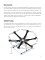
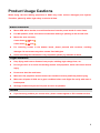
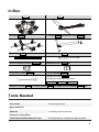
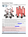
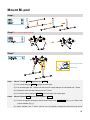
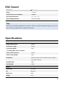
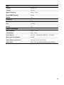
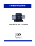
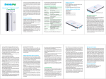
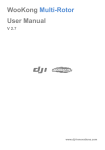
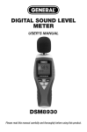
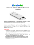
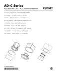
Spreading Wings S800 User Manual V 1.0 www.dji-innovations.com 1 Disclaimer Read this disclaimer carefully before using Spreading Wings S800. By using this product, you hereby agree to this disclaimer and signify that you have read them fully. Spreading Wings S800 is an excellent multi-rotor. With a good autopilot, it will offer tremendous flight features. Despite the controller of DJI autopilot operate in the safest manner when the main power battery is connected, we strongly recommend customers to remove all frame arms, and keep children away during system calibration and parameter setup. Dajiang Innovation Technology Co. Ltd. (DJI) assumes no liability for damage(s) or injuries incurred directly or indirectly from this product usage. S800 Profile DJI Spreading Wings S800 is a multi-rotor designed for AP. It simplifies users’ installation and enables quick disassembling. Frame arm integrates with ESC and motor. With DJI WKM autopilot system, it can achieve hovering, cruising and other flight elements. S800 can be applied for aerial photography and other aero-modeling activities. 350mm(Lenghth) 240mm(Diam eter) m th) 5 m id 14 p W o (T 320mm(Height) 41 5m m (W id th ) 50 0m Le m( ng th) 2 Contents Disclaimer.......................................................................................................................2 S800 Profile ....................................................................................................................2 Contents .........................................................................................................................3 Product Usage Cautions.................................................................................................4 In Box .............................................................................................................................5 Tools Needed .................................................................................................................5 Center Frame Wiring ......................................................................................................6 Mount Center Frame ......................................................................................................7 Mount Frame Arms .........................................................................................................8 Mount Bi-pod ................................................................................................................10 Assembly ......................................................................................................................12 ESC Sound...................................................................................................................13 Specifications ...............................................................................................................13 Appendix ......................................................................................................................15 3 Product Usage Cautions When flying, the fast rotating propellers of S800 may cause serious damage(s) and injuries. Therefore, please fly with a high safety in mind at all time. Mount Attention Mount GPS with a bracket, to avoid interference from the power board of center frame. For IMU position, make sure the arrow direction marking is pointing to the aircraft nose. Mount the arms correctly. Center frame Arm Center frame Arm For removing screws in the bottom board, please proceed with cautious, avoiding damages. Do not remove any other screws fixed with glue. Notice matching the indications is very important, please pay attention to them. Flight Attention Keep flying multi-rotor a distance from people, building, high-voltage lines, etc. Do not get close to or touch the working motors and propellers, which will cause serious injury. Do not over load the multi-rotor. Make sure the propellers and the motors are installed correctly and firmly before flying. Make sure all parts of S800 are in good condition before each flight. Do not fly with wore or broken parts. Strongly recommend you use DJI parts as much as possible. Others If you have any problem you cannot solve, please contact agents or DJI customer service. 4 In Box Center Frame 800CF×1 Frame Arm 800FA×6 H Frame 800HF ×1 T Frame 800TF×2,Aluminum Ring 800AR×2 Base Pipe 800BP×2 Bi-pod Drawbar 800BD×4 Silicone Rubber Damper 800SRD×4 Nonslip Damper 800ND×4 3-PIN Servo Cable 800SC ×1 Screw Package 800SP ×1 Hexagonal screws: M2.5×5 Hexagonal socket head cap screws: HC-M2.5×5, HC-M2.5×8, HC-M3.0×22 Adhesive Velcro 800AV ×1, Battery Band 800BB ×2, Spare Screw Package 800SSP ×1 Tools Needed 2.0mm Hex Wrench, 2.5mm Hex Wrench For mounting screws. Screw Glue For fastening screws. Nylon Cable Tie Scissors For binding devices and wires. Diagonal Cutting Pliers Foam Double Sided Adhesive Tape For fixing receiver, controller and other modules. 5 Center Frame Wiring The top board is power distribution board, and the bottom board is for loading autopilot system components. Buckle Top Board Bottom Board Slot Aircraft Nose Top Board Mark Motor clock-wise AL Motor number 2 M 1 MB GI M ESC signal outlet To main controller Mark M 1 M M 2 M 3 M 4 5 M 6 XT60 Female To Gimbal Circuit line BA TT M3 M6 Parallel Mark Motor count clock-wise XT60 Male IMU Front PM To Battery IMU mount position M XT60 Female 4 5 M To PMU Notices: For IMU position, make sure the arrow direction marking is pointing to the aircraft nose. Connect the motor 3-pin connector (M1~M6) from WKM M.C. to ESC signal socket (M1~M6) on center frame markings accordingly. (WKM M.C. M1 ESC signal socket M1, …… , WKM M.C. M6 ESC signal socket M6) Tips: Main battery power leads, gimbal and PMU leads are on the bottom surface of the top board. Markings and stand for the propeller rotation direction. means clock-wise, and means counter clock-wise. If you need other lead connector, please cut the original connector and solder on the new connector. (But not Recommend) 6 Mount Center Frame Remove Screws Fix Screws Step1: Mount IMU module into IMU position in the center frame. Ensure IMU casing is out of touch the top board edge, as vibration can cause IMU mal-function. Step2: Please mount DJI Autopilot System parts onto the bottom board (not including GPS modules). Please remove all the screws from the bottom board first if necessary. Step3: Connect Autopilot System and receiver. Please refer to DJI WKM User Manual for details. Step4: Please mount the screws to bottom board, and use adequate screw glue. Step5: Mount the GPS on the top board with a bracket. Step6: Configure Autopilot System. Please refer to DJI WKM User Manual. Notices: Make sure to mount the IMU module at the IMU position first. Mount the GPS with a bracket, to avoid interference from center frame power board. Ensure the USB port of the M.C. outwards for easy access. Please wire neatly. Make sure wires will not be cut by the edge of frames. Tips: Install screws with appropriate strength to prevent damage threads. 7 Mount Frame Arms Step 1 Step 2 800CF ×1 800FA ×6 Copper contacts Propeller Screw Cover Motor ESC LED Motor rotation direction (1) Clock-wise Counter clock-wise Red Green Step 3 Step 4 Step 5 800CF ×1 800FA ×6 800CF ×1 800FA ×6 Vertical 35o Horizontal Horizontal (2) Step1: Check arms. (1) Make sure copper contacts are in good condition without bend or severe wear. (2) Make sure propellers are without crack, and screws in propeller cover tight. (3) Make sure motors are mounted firmly, and rotate freely. (4) Distinguish LED indicator on the ESC bottom. With a red point in is red LED, others are green LED. We recommend you mount arms with red LED to M1 and M2. (5) Distinguish marks and Arm Center frame Arm Center frame on the arms. Step2: Insert frame arm into center frame vertically. Step3: Slowly rotate the frame arm upward until positioned completely. Step4: Press down the buckle to lock the arm. Make sure the arm does not move. Step5: Make sure the buckle is pressed down correctly, about 35o under normal circumstances. Notices: Please add some lubricant at the position (1) if it is hard to press down the buckle. Slowly rotate the frame arm to prevent from breaking the copper contacts. Please refer to (2) to ensure the arm is perfectly positioned. Make sure use appropriate strength to press down the buckle correctly. Do not hot plug arms. If the motor mount become loosens, please tighten it by following the procedures in Appendix. Tips: LED is on after motor start. Examination Arms①②are aircraft nose direction, arms④⑤ are aircraft tail. See from top, motors on arms①③⑤ rotate counter clockwise; motors on arms②④⑥ rotate clockwise. ② ③ rc Ai e os N ft ra ① ④ ⑤ ⑥ 9 Mount Bi-pod Step1 Step2 (Fix, but not tighten screws) Step3 H frame bulges outwards T frame notch Step1: Mount T frame 800TF and base pipe 800BP. (1) Put nonslip damper 800ND through the base pipe. (2) Put the base pipe into T frame until the head of nonslip damper is embedded into T frame. (3) Embed the other nonslip damper into the T frame. (4) Put silicon rubber damper 800SRD onto both sides of the base pipe. Step2: Mount H frame800HF and bi-pod drawbars 800BD. (1) Fix (but not tighten) hexagonal socket head cap screws HC-M2.5×5 (Fig.①) to H frame and bi-pod drawbar (Fig.①). (2) Adjust drawbar and T frame, and fix (but not tighten) hexagonal socket head cap screw 10 HC-M2.5×5 (Fig.②) to drawbar and aluminum ring 800AR. Step3: Mount H frame and T frame. (1) Insert T frame through aluminum ring until it plugs into H frame. (2) Fix T frame notch into H frame bulges outwards, make sure T frame will not move. (3) Put the bi-pod on the flat floor to adjust H frame and T frame. (4) Tighten all hexagonal socket head cap screws (including ① and ②). Notices: Put bi-pod on the flat floor to finish mounting smoothly and correctly. Please mount the screws and use adequate screw glue. Separate the bi-pod by disconnecting the H frame to make for easy carriage. Completed Quick Disassembly 11 Assembly Assembly ② ③ rc Ai N ft ra e os ① ④ ⑤ ⑥ Align knob to mark Insert knob into arm Rotate knob (2) (1) Knob Mark Step1: Align all knobs on the H frame to the marks; refer to fig (1). Step2: Lie frame and bi-pod horizontally, insert knobs into arms ③ and ⑥ first, and then adjust to insert others into the arms. Step3: Rotate the knob to the end, as fig (2) shown. Notices: Ensure all knobs on the H frame aligned to the marks, and they would go through the arms successfully. Tips: It is convenient for you to carry S800 by quick disassembly (Frame, Bi-pod, Frame and Bi-pod). 12 ESC Sound ESC State Sound Ready ♪1234567 Throttle stick is not at bottom BBBBBB… Input signal abnormal B--------B--------B… Input voltage abnormal BB---BB---BB---BB… Tips: DJI ESCs are specially designed for multi-rotors. When use with DJI autopilot systems, you do not have to setup any parameters or calibrate travel range. Specifications Frame Diagonal Wheelbase 800mm Frame Arm Length 350mm Frame Arm Weight 304g (Including Motor, ESC, Propeller ) Center Frame Diameter 240mm Center Frame Weight 365g Bi-pod Size 500mm(Length)×415mm(Width)×320mm(Height) (Top width: 145mm) Bi-pod Weight 428g Total Weight 2.6Kg Motor Stator Size 41×14mm KV 320rpm/V Max Power 360W Weight 147g 13 ESC Current 40A OPTO Voltage 6S LiPo Signal Frequency 30Hz ~ 450Hz Drive PWM Frequency 24KHz Weight 18g Propeller Material Carbon Fiber Size 15×04in Weight 15g Flight Parameters Takeoff Weight 5.0Kg ~ 7.0Kg Load Weight 0Kg ~ 2.5Kg Power Battery LiPo (6S、10000mAh~15000mAh、15C(Min)) Max Power Consumption 2100W Hover Power Consumption 720W(@ Takeoff Weight 6Kg) Hover Time Max: 16 min (@10000mAh&6KgTakeoff Weight) 14 Appendix Step1 For arms For arms Shim Step2 Motor mount screws Step3 For arms For arms Step1: Remove. Please unscrew the screws on the top. Step2: Tighten. Retighten the motor mount screws on the back to make the motor firmly attached. Step3: Remount. Remount the screws on the top. Notices: Shim should be mounted in the correct position, as shim mount position of arm is different from arm . Tips: Please use adequate screw glue. Install screws with appropriate strength. 15 Spreading Wings S800 ©2012 Dajiang Innovation Technology Co. Ltd. All Rights Reserved. 6/F, HKUST SZ IER Building, No.9, Yuexing 1st Rd., South District, Hi-Tech Park, Shenzhen, 518057, Guangdong, China Tel: +86-755-2665-6677 Sales ext: 201, 202, 203 Fax: +86-755-83067370 Service hotline: +86-755-22673777 Sales: [email protected] Technical support: [email protected] Others: [email protected] DJI Spreading Wings is registered trademark of Dajiang Innovation Technology Co. Ltd. Names of product, brand, etc., appearing in this manual are trademarks or registered trademarks of their respective owner companies. This product and manual are copyrighted by Dajiang Innovation Technology Co. Ltd. with all rights reserved. No part of this product or manual shall be reproduced in any form without the prior written consent or authorization of Dajiang Innovation Technology Co. Ltd. No patent liability is assumed with respect to the use of the product or information contained herein. 16