1
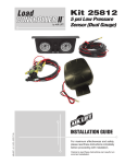
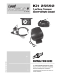
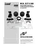
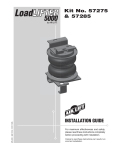
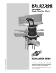
™
Kits 25415,
25430
MN-601 • (161203) • ECR 7303
Magnetic Height Sensor
INSTALLATION GUIDE
For maximum effectiveness and safety,
please read these instructions completely
before proceeding with installation.
Failure to read these instructions can result in an
incorrect installation.
SmartAir
TABLE OF CONTENTS
Introduction . . . . . . . . . . . . . . . . . . . . . . . . . . . . . . . . . . . 2
Important System Information . . . . . . . . . . . . . . . . . . . . . . . . . . . . . . . . . . . . . . . . 2
Notation Explanation . . . . . . . . . . . . . . . . . . . . . . . . . . . . . . . . . . . . . . . . . . . . . . . . 2
Installation Diagram . . . . . . . . . . . . . . . . . . . . . . . . . . . . 3
Hardware List . . . . . . . . . . . . . . . . . . . . . . . . . . . . . . . . . . . . . . . . . . . . . . . . . . . . . 3
Installing the SmartAir System . . . . . . . . . . . . . . . . . . . 4
Recommended Compressor Locations . . . . . . . . . . . . . . . . . . . . . . . . . . . . . . . . . . 4
Installing the Compressor and Deflate Solenoid . . . . . . . . . . . . . . . . . . . . . . . . . . . 4
Attaching the Height Sensor . . . . . . . . . . . . . . . . . . . . . . . . . . . . . . . . . . . . . . . . . . 5
Attaching the Magnet and Mounting Bracket. . . . . . . . . . . . . . . . . . . . . . . . . . . . . . 5
Installing the Electrical Components . . . . . . . . . . . . . . . . . . . . . . . . . . . . . . . . . . . . 6
Adjusting the System . . . . . . . . . . . . . . . . . . . . . . . . . . . . . . . . . . . . . . . . . . . . . . . . 8
Checking the System. . . . . . . . . . . . . . . . . . . . . . . . . . . . . . . . . . . . . . . . . . . . . . . . 8
Troubleshooting Guide . . . . . . . . . . . . . . . . . . . . . . . . . 9
Troubleshooting Diagram . . . . . . . . . . . . . . . . . . . . . . . . . . . . . . . . . . . . . . . . . . . . 9
Troubleshooting Guide . . . . . . . . . . . . . . . . . . . . . . . . . . . . . . . . . . . . . . . . . . . . . . 9
Product Use . . . . . . . . . . . . . . . . . . . . . . . . . . . . . . . . . . . 10
Frequently Asked Questions . . . . . . . . . . . . . . . . . . . . . . . . . . . . . . . . . . . . . . . . . .10
Tuning the Air Pressure . . . . . . . . . . . . . . . . . . . . . . . . . . . . . . . . . . . . . . . . . . . . . .10
Guidelines for Adding Air . . . . . . . . . . . . . . . . . . . . . . . . . . . . . . . . . . . . . . . . . . . . .11
Warranty and Returns Policy . . . . . . . . . . . . . . . . . . . . . 11
Replacement Information . . . . . . . . . . . . . . . . . . . . . . . . 12
Contact Information . . . . . . . . . . . . . . . . . . . . . . . . . . . . 12
MN-601
1
SmartAir
Introduction
The purpose of this publication is to assist with the installation, maintenance and
troubleshooting of the SmartAir System.
It is important to read and understand the entire installation guide before beginning installation
or performing any maintenance, service or repair. The information here includes a hardware
list, tool list, step-by-step installation information, maintenance tips, safety information and
a troubleshooting guide.
Air Lift Company reserves the right to make changes and improvements to its products and
publications at any time. For the latest version of this manual, contact Air Lift Company at
(800) 248-0892 or visit our website at www.airliftcompany.com.
IMPORTANT SYSTEM INFORMATION
The system is comprised of an Electronic Height Sensor (EHS), a bracket mounted magnet,
solenoid valve, relay, air compressor, and an interconnecting wire harness. This system is
combined with the previously installed air bags.
The EHS is mounted to the vehicle frame and the magnet is mounted to the axle or leaf
spring. When load is added to the vehicle, the magnet rises above the EHS centerline (as
the suspension is compressed). If the magnet maintains this position for a minimum of 25
seconds, the EHS will turn on the compressor, via the relay, adding air to the air bags. Air
is added until the magnet is re-centered restoring the vehicle to its preset ride height.
When load is removed from the vehicle, the magnet falls below the EHS and energizes the
solenoid valve. This allows the air to escape from the air bags until the magnet is re-centered
and the reduction in load is accomodated.
An optional kneeling system can be purchased, which includes a dash mounted rocker
switch. This system works to manually exhaust air from the bags when a lower vehicle is
needed while parking.
NOTATION EXPLANATION
Hazard notations appear in various locations in this publication. Information which is
highlighted by one of these notations must be observed to help minimize risk of personal injury
or possible improper installation which may render the vehicle unsafe. Notes are used to help
emphasize areas of procedural importance and provide helpful suggestions. The following
definitions explain the use of these notations as they appear througout this guide.
DANGER
INDICATES IMMEDIATE HAZARDS WHICH WILL RESULT IN SEVERE PERSONAL
INJURY OR DEATH.
WARNING
INDICATES HAZARDS OR UNSAFE PRACTICES WHICH COULD RESULT IN SEVERE
PERSONAL INJURY OR DEATH.
CAUTION
INDICATES HAZARDS OR UNSAFE PRACTICES WHICH COULD RESULT IN DAMAGE
TO THE MACHINE OR MINOR PERSONAL INJURY.
NOTE
2
Indicates a procedure, practice or hint which is important to highlight.
MN-601
MN-601
Enlarged View
Side View
20 AMP
Optional Ring Terminal.
Connect Wire to a 12V
constant on power source.
(Use terminal if connecting
to battery.)
24050
16092
26238
26687
20220
Part #
I
85
87
30
86
Back View
Compressor
This will not be
attached to anything
unless the kneeling
switch option is used.
Portion of Harness
Inside Cab
A
B
C
D
E
Item
Compressor (-) (6)
P
N
O
5 AMP
F
mount forward of axle
Compressor (+) (5)
Q
R
V Battery
(1)
Valve (-) (4)
Splice into
keyed on
ignition wire.
Inside View of
Connector
M
G
THIS END UP
ALIGN DOTTED
LINE WITH CENTER
OF MAGNET
J
Electronic Magnetic Height Sensor .....1
Compressor ........................................1
Exhaust Solenoid Assembly ...............1
Harness...............................................1
1/4” Air Line........................................20’
Description.................................Qty
HARDWARE LIST
C
View of magnet
from other side
E
Exhaust tube
Do not connect to system.
Must vent to atmosphere.
A
(1)
D
L
GND
(2)
K
S
10966
10967
10466
21838
17173
17185
18417
18600
18498
10583
01426
18435
18444
17132
26833
Part #
Orange dot
(or chamfered side)
will face the inside of
the vehicle towards
the height sensor.
F
G
H
I
J
K
L
M
N
O
P
Q
R
S
T
Item
I
Solenoid - (4)
Solenoid + (3)
T
B
Ground
J
fig. 1
Compressor mounting
hardware is included
with the compressor.
Compressor
Magnet ................................................1
Magnet Mounting Bracket ...................1
8” Black Zip Tie ..................................12
1/4” x 1/4” x 1/4” Union Tee ................4
1/4” x 3/4” Self-Tapping Screw ...........3
#8 - 32 x 3/8” Washer Head Screw .....2
#8 Lock Washer ..................................2
#10 - 24 x 1.25” Socket Cap Screw ....1
3/16 - 24 Nyloc Nut .............................1
3/8” x 3.5” x 4.5” U-bolt .......................1
Clamp Bar ...........................................1
3/8” - 16 Nyloc Nut ..............................2
3/8” Flat Washer .................................2
#8 - 18 x 1/2” Self-Tapping Screw ......1
Pressure Release Valve Assembly .....1
Description.................................Qty
SmartAir
Installation Diagram
3
SmartAir
Installing the SmartAir System
RECOMMENDED COMPRESSOR LOCATIONS
Important
LOCATE COMPRESSOR IN DRY, PROTECTED AREA ON VEHICLE.
DIRECT SPLASH OR EXCESSIVE MOISTURE CAN DAMAGE
THE COMPRESSOR AND CAUSE SYSTEM FAILURE.
Disclaimer: If you choose to mount the compressor outside the vehicle please keep in
mind the compressor body must be shielded from direct splash and the intake should be
snorkeled inside the vehicle. If the compressor does not include a remote mount air filter or
if mounting the compressor outside the vehicle, make sure to orient the compressor intake
filter so that all moisture can easily drain.
Please also remember...
• To avoid high heat environments
• To avoid mounting the compressor under the hood.
• To check to be sure the compressor harness #2 will reach the compressor and connect
to harness #1.
• The compressor can be mounted in any position — vertical, upside down, sideways,
etc. (please refer to the instruction manual).
INSTALLING THE COMPRESSOR AND DEFLATE SOLENOID
1. Attach the filter to the fitting on the end of the compressor.
2. Select a rigid mounting location on your vehicle’s frame or crossmember that shields
the compressor from the elements and heat sources (fig. 2). Refer to chart below for
step-by-step instructions.
NOTE
CAUTION
The compressor and deflate solenoid must be mounted within reach of the wires when the
wiring harness is plugged in.
MOUNT THE COMPRESSOR AND DEFLATE SOLENOID AT LEAST 6” FROM ANY HEAT
SOURCES. DO NOT MOUNT THE COMPRESSOR OR THE MANIFOLD IN THE ENGINE
COMPARTMENT.
Exhaust
Solenoid
Pressure Relief
Valve Assembly
Union Tee
Compressor
mounting
hardware is
included with
the compressor.
Ground
Exhaust Tube
Do not connect to system.
Must vent to atmosphere.
Compressor
To air spring
4
fig. 2
MN-601
SmartAir
1
2
3
Compressor
Centerpunch and drill four
1/4” diameter holes using
the compressor feet as a
template.
Attach using four
supplied screws.
Solenoid
Centerpunch and drill
two 3/16” diameter holes
using the template on the
back of the manual?
Attach using two
supplied lock washers
and bolts.
Fasten using four
supplied nuts.
3. Cut a length of air line and remove the compression nut in the end of the leader hose
and slip it over the air line. Insert the barb on the leader hose into the air line, seating
it completely against the leader hose fitting. Thread the nut onto the fitting and tighten.
Connect the other end of the air line to one of the push-to-connect fittings on the tee of
the pressure relief valve assembly (fig. 2).
4. Cut another length of air line and attach one end to the open push-to-connect fitting on
the tee of the assembly and the other end of the air line to the solenoid valve.
NOTE
It may be necessary to stabilize the pressure relief valve assembly. If so, use a tie strap
and attach it to the frame rail or a crossmember.
5. Attach the compressor and deflate solenoid to the frame rail or crossmember using fig.
2 as a guide.
6. Mount the solenoid as close to the compressor or air spring as possible (fig. 2). Use the
template on the back of the manual for mounting the solenoid.
CAUTION
MOUNT THE COMPRESSOR AND DEFLATE SOLENOID AT LEAST 6” FROM ANY HEAT
SOURCES. DO NOT MOUNT THE COMPRESSOR OR THE MANIFOLD IN THE ENGINE
COMPARTMENT.
ATTACHING THE HEIGHT SENSOR
1. Choose a mounting location along the frame rail for the height sensor.
NOTE
Preferably mount the height sensor forward of the axle.
2. Using the provided screws and nyloc nuts, attach the height sensor to the chosen framemounting location (fig. 3).
CAUTION
STAY CLEAR OF ANYTHING THAT MAY HIT THE HEIGHT SENSOR WHILE THE
SUSPENSION TRAVELS IN JOUNCE AND COMPRESSION.
THIS END UP
ALIGN DOTTED
LINE WITH CENTER
OF MAGNET
fig. 3
ATTACHING THE MAGNET AND MOUNTING BRACKET
CAUTION
THE MAGNET HAS A STRONG PULL. USE CARE WHEN HANDLING AS NOT TO PINCH
FINGERS OR SKIN.
1. Place the supplied u-bolt around the leaf springs near the previously mounted height
sensor (fig. 4 and fig. 5).
MN-601
5
SmartAir
2. Using the figures below as a guide, choose the best mounting method for your
vehicle.
NOTE
When choosing the mounting method, keep in mind that the center of the magnet must align
with the height sensor when the vehicle is at ride height. The magnet and the height sensor
must be between 1”- 1½” apart.
3. Attach the bracket to the u-bolt using the chosen mounting method per fig. 4 and fig. 5.
4. Loosely attach the magnet to the bracket using the supplied bolt and nyloc nut.
NOTE
There is a small orange dot (or chamfered side) on the magnet that will face the inside of
the vehicle towards the height sensor.
5. Align the center of the magnet with the dotted line on the height sensor. Once the magnet
is in line, securely tighten the hardware.
Electronic Height
Sensor (EHS)
There must be
1” - 1½” between
the magnet and
the EHS.
There must be
1” - 1½” between
the magnet and
the EHS.
Electronic Height
Sensor (EHS)
Nyloc Nut
Nyloc Nut
Magnet Bracket
Magnet Bracket
(attached to u-bolt)
(mounted between
the clamp bar and
leaf spring)
Frame
Magnet
Magnet
Orange dot (or
chamfered side)
faces EHC)
Orange dot (or
chamfered side)
faces EHC)
Axle
fig. 4
Frame
Axle
fig. 5
INSTALLING THE ELECTRICAL COMPONENTS
1. Run the harness from the cab to the solenoid/compressor location.
NOTE
It may be necessary to drill a hole so that the harness can easily pass through from the
cab to the vehicle frame. Place a grommet or silicone sealant around any holes that the
harness passes through to protect it from abrasive surfaces.
2. Connect single terminal connectors to connect the black compressor wire to the relay
wire (fig. 6).
3. Connect the double terminal connector from the solenoid to the double terminal connector
relay wires (fig. 6).
4. Splice the red wire with the 5 AMP fuse that is connected to the back of the relay to a
keyed on ignition wire (fig. 7).
5. Using a butt connector, attach the 12 gauge wire from the terminal 30 on the back of the
relay to one end of the 20 amp fuse holder (fig. 8).
6. If choosing to use the ring terminal, attach it to the other end of the fuse wire (fig. 8).
7. Choose an appropriate 12+ volt source on the vehicle.
NOTE
A direct connection to the battery is suggested.
8. Attach the terminal end of the ground wire to a clean section of the framerail using the
provided self-tapping screw (fig. 9).
6
MN-601
SmartAir
Solenoid Wires
Ground
Compressor Wire
Relay
Harness
fig. 6
Inside View of
Connector
Splice into keyed
on ignition wire.
fig. 7
5 AMP
Optional Ring Terminal
Connect wire to a 12V
constant on power
source. (Use terminal if
connecting to battery.)
20 AMP
Back View
30
85 86
87
fig. 8
Ground
fig. 9
MN-601
7
SmartAir
ADJUSTING THE SYSTEM
1. Make sure that the distance between the face of the magnet and the electronic height
sensor (EHS) is between 1” to 1-1/2”.
2. As stated in figure one, the orange dot (or chamfered side) on the magnet must be facing
the EHS.
CAUTION
THIS MAGNET IS VERY STRONG. IT IS POSSIBLE FOR THE MAGNET TO PINCH SKIN
AND SMALL BODY PARTS BETWEEN ANOTHER MAGNET OR METAL OBJECT. CARE
SHOULD BE TAKEN WHEN HANDLING THE MAGNET.
3. You can adjust the suspension by moving the magnet up or down in the slotted mounting
bracket. It is recommended that the magnet be set a half inch below the center of the
EHS to start. Take a reference measurement from ground to the rear bumper or the
wheel well.
4. Turn the ignition key to the accessory or on position.
NOTE
You should hear the system cycle (deflate and inflate) every time the key is turned on in an
unladen condition. This is a system maintenance function to maintain the minimum PSI in
the rear air springs. If the vehicle is laden, the key-on function will be disabled by the EHS.
The preferred method of adjusting the system would be to laden the vehicle with a load,
then adjust the magnet so that the suspension obtains the height you desire. Usually a good
starting point would be to set the vehicle (using the magnet) at a level ride height, or one
inch below the stock curb height unladen (using the measurement taken in step 3).
NOTE
There is a 25 second delay in the system. Once the magnet is set in position and no movement
is detected by the EHS, it will take 25 seconds for the compressor, or the deflate solenoid,
to turn on and level the vehicle by inflating, or deflating, the air springs in the suspension.
Once the desired ride height is obtained, tighten the magnet mounting screw snug, do not
over tighten.
CHECKING THE SYSTEM
1. Inspect all air line connections with a solution of 1/5 dish soap to 4/5 water. Should a
leak be detected in a push-lock-fitting, reinstall the air line to the fitting. Make sure air
line is cut off squarely and that the air line is completely pushed into the fitting.
2. If the compressor or the solenoid fails to function, check the 20 AMP fuse and ground
connection. Repair and replace as necessary.
8
MN-601
SmartAir
Troubleshooting Guide
Template For Drilling Holes
V Battery (1)
5 AMP
Valve (-) (4) (Not Used)
Compressor (+) (5)
20 AMP
Valve (+) (3)
Back View
Compressor (+) (5)
30
85
86
Compressor (-) (6)
87
Ground
Ignition
Valve (-) (4)
Compressor
Harness Magnetic
Height Sensor Connector
O
fig. 10
N
Compressor
Ground
J
PROBLEM
CAUSE
B
SOLUTION
The system has a 25 second delay before the compressor and solenoid will function.
Compressor doesn’t run.
Blown fuse, bad ground, poor Check fuses, grounds and connections. Ground
connection, bad compressor or terminal 85 at relay to see if compressor runs.
ECU.
Unplug compressor and test.
Solenoid doesn’t work.
Blown fuse, bad connections, bad Check fuse, connection, unplug solenoid and
solenoid or ECU.
jumper power and ground to check operation.
Compressor runs all the Leak in system, bad relay or ECU. Locate leak, replace relay or check ECU.
time.
Vehicle does not maintain Bad/leaking solenoid or bad ECU.
ride height.
Unplug solenoid and test by jumping power
and ground.
Nothing happens when the B l o w n f u s e , p o o r g r o u n d o r Check fuses, connections and grounds.
vehicle is started.
connection.
Bad ECU.
Test individual components to verify and ground
terminal 85 to test compressor and harness.
Magnet may not be properly Check magnet alignment, distance, and insure
aligned, may be backward or may orange dot (or chamfered side) is facing ECU.
be improper distance from ECU.
MN-601
9
SmartAir
Product Use
FREQUENTLY ASKED QUESTIONS
Q. Will installing air springs increase the weight ratings of a vehicle?
No. Adding air springs will not change the weight ratings (GAWR, GCWR and/or GVWR)
of a vehicle. Exceeding the GWVR is dangerous and voids the Air Lift warranty.
Q. Is it necessary to keep air in the air springs at all times and how much pressure
will they need?
The minimum air pressure should be maintained at all times. The minimum air pressure
keeps the air spring in shape, ensuring that it will move throughout its travel without
rubbing or wearing on itself.
Q. Is it necessary to add a compressor system to the air springs?
No. Air pressure can be adjusted with any type of compressor as long as it can produce
sufficient pressure to service the springs. Even a bicycle tire pump can be used, but it’s
a lot of work.
Q. How long should air springs last?
If the air springs are properly installed and maintained they can last indefinitely.
Q. Will raising the vehicle on a hoist for service work damage the air springs?
No. The vehicle can be lifted on a hoist for short-term service work such as tire rotation
or oil changes. However, if the vehicle will be on the hoist for a prolonged period of time,
support the axle with jack stands in order to take the tension off of the air springs.
TUNING THE AIR PRESSURE
Pressure determination comes down to three things — level vehicle, ride comfort, and
stability.
1. Level vehicle
If the vehicle’s headlights are shining into the trees or the vehicle is leaning to one side,
then it is not level (fig. 11). Raise the air pressure to correct either of these problems
and level the vehicle.
2. Ride comfort
If the vehicle has a rough and harsh ride it may be due to either too much pressure or
not enough (fig. 12). Try different pressures to determine the best ride comfort.
3. Stability
Stability translates into safety and should be the priority, meaning the driver may need
to sacrifice a perfectly level and comfortable ride. Stability issues include roll control,
bounce, dive during braking and sponginess (fig. 13). Tuning out these problems usually
requires an increase in pressure.
Bad headlight aim
fig. 11
Rough ride
fig. 12
fig. 13
Sway and body roll
10
MN-601
SmartAir
GUIDELINES FOR ADDING AIR
1. Start with the vehicle level or slightly above.
2. When in doubt, always add air.
3. For motorhomes, start with 50-100 PSI in the rear because it can be safely assumed
that it is heavily loaded.
4. If the front of the vehicle dives while braking, increase the pressure in the front air bags, if
equipped.
5. If it is ever suspected that the air bags have bottomed out, increase the pressure (fig. 14).
6. Adjust the pressure up and down to find the best ride.
7. If the vehicle rocks and rolls, adjust the air pressure to reduce movement.
8. It may be necessary to maintain different pressures on each side of the vehicle. Loads
such as water, fuel, and appliances will cause the vehicle to be heavier on one side (fig.
15). As much as a 50 PSI difference is not uncommon.
Bottoming out
fig. 14
Unlevel
Level
fig. 15
Warranty and Returns Policy
Air Lift Company warrants its products, for the time periods listed below, to the original
retail purchaser against manufacturing defects when used on catalog-listed applications on
cars, vans, light trucks and motorhomes under normal operating conditions for as long as
Air Lift manufactures the product. The warranty does not apply to products that have been
improperly applied, improperly installed, used in racing or off-road applications, used for
commercial purposes, or which have not been maintained in accordance with installation
instructions furnished with all products. The consumer will be responsible for removing
(labor charges) the defective product from the vehicle and returning it, transportation costs
prepaid, to the dealer from which it was purchased or to Air Lift Company for verification.
Air Lift will repair or replace, at its option, defective products or components. A minimum
$10.00 shipping and handling charge will apply to all warranty claims. Before returning
any defective product, you must call Air Lift at (800) 248-0892 in the U.S. and Canada
(elsewhere, (517) 322-2144) for a Returned Materials Authorization (RMA) number.
Returns to Air Lift can be sent to: Air Lift Company • 2727 Snow Road • Lansing, MI •
48917.
Product failures resulting from abnormal use or misuse are excluded from this warranty. The
loss of use of the product, loss of time, inconvenience, commercial loss or consequential
damages is not covered. The consumer is responsible for installation/reinstallation (labor
charges) of the product. Air Lift Company reserves the right to change the design of any
product without assuming any obligation to modify any product previously manufactured.
This warranty gives you specific legal rights and you may also have other rights that vary
from state-to-state. Some states do not allow limitations on how long an implied warranty
lasts or allow the exclusion or limitation of incidental or consequential damages. The above
limitation or exclusion may not apply to you. There are no warranties, expressed or implied
including any implied warranties of merchantability and fitness, which extend beyond this
warranty period. There are no warranties that extend beyond the description on the face
hereof. Seller disclaims the implied warranty of merchantability. (Dated proof of purchase
required.)
MN-601
11
SmartAir
Air Lift 1000 .................... Lifetime Limited
RideControl .................... Lifetime Limited
LoadLifter 5000*............. Lifetime Limited
SlamAir ........................... Lifetime Limited
AirCell ............................. Lifetime Limited
Air Lift Performance** .......... 1 Year Limited
LoadController/Single ...... 2 Year Limited
LoadController/Dual ......... 2 Year Limited
Load Controller (I) ............ 2 Year Limited
Load Controller (II) ........... 2 Year Limited
SmartAir ............................ 2 Year Limited
Wireless AIR...................... 2 Year Limited
WirelessONE ..................... 2 Year Limited
Other Accessories ............ 2 Year Limited
*formerly SuperDuty
**formerly LifeStyle & Performance and EasyStreet
Replacement Information
If you need replacement parts, contact the local dealer or call Air Lift customer service at
(800) 248-0892. Most parts are immediately available and can be shipped the same day.
Contact Air Lift Company customer service at (800) 248-0892 first if:
• Parts are missing from the kit.
• Need technical assistance on installation or operation.
• Broken or defective parts in the kit.
• Wrong parts in the kit.
• Have a warranty claim or question.
Contact the retailer where the kit was purchased:
• If it is necessary to return or exchange the kit for any reason.
• If there is a problem with shipping if shipped from the retailer.
• If there is a problem with the price.
Contact Information
If you have any questions, comments or need technical assistance contact our customer service
department by calling (800) 248-0892, Monday through Friday, 8 a.m. to 8 p.m. Eastern Time.
For calls from outside the USA or Canada, our local number is (517) 322-2144.
For inquiries by mail, our address is PO Box 80167, Lansing, MI 48908-0167. Our shipping
address for returns is 2727 Snow Road, Lansing, MI 48917.
You may also contact us anytime by e-mail at [email protected] or on the web at
www.airliftcompany.com.
12
MN-601
SmartAir
Notes
MN-601
13
Need Help?
Contact our customer service department by calling
(800) 248-0892, ext. 1, Monday through Friday, 8 a.m.
to 8 p.m. Eastern Time. For calls from outside the
USA or Canada, our local number is (517) 322-2144.
Thank you for purchasing Air Lift products — the professional installer’s choice!
Air Lift Company • 2727 Snow Road • Lansing, MI 48917 or PO Box 80167 • Lansing, MI 48908-0167
Toll Free (800) 248-0892 • Local (517) 322-2144 • Fax (517) 322-0240 • www.airliftcompany.com
Printed in
the USA