1
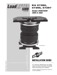
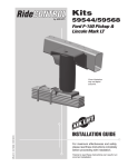
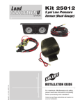
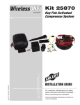
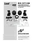
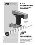
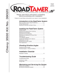
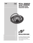
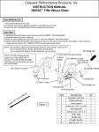
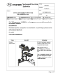
Kit 60818
MN-704 • (02905) • ECR 6701
Dodge 1500 Pickup,
2 & 4WD
INSTALLATION GUIDE
For maximum effectiveness and safety,
please read these instructions completely
before proceeding with installation.
Failure to read these instructions can result in an
incorrect installation.
Air Lift 1000
2
MN-704
Air Lift 1000
TABLE OF CONTENTS
Introduction . . . . . . . . . . . . . . . . . . . . . . . . . . . . . . . . . . . 2
Important Safety Notice . . . . . . . . . . . . . . . . . . . . . . . . . . . . . . . . . . . . . . . . . . . . . 2
Notation Explanation . . . . . . . . . . . . . . . . . . . . . . . . . . . . . . . . . . . . . . . . . . . . . . . . 2
Installing the Air Lift 1000 System . . . . . . . . . . . . . . . . . 3
Hardware List . . . . . . . . . . . . . . . . . . . . . . . . . . . . . . . . . . . . . . . . . . . . . . . . . . . . . 3
Tools List . . . . . . . . . . . . . . . . . . . . . . . . . . . . . . . . . . . . . . . . . . . . . . . . . . . . . . . . . 3
Getting Started . . . . . . . . . . . . . . . . . . . . . . . . . . . . . . . . . . . . . . . . . . . . . . . . . . . . 3
Installing the Air Spring . . . . . . . . . . . . . . . . . . . . . . . . . . . . . . . . . . . . . . . . . . . . . . 4
Installing the Air Line . . . . . . . . . . . . . . . . . . . . . . . . . . . . . . . . . . . . . . . . . . . . . . . . 5
Tee Air Line Routing . . . . . . . . . . . . . . . . . . . . . . . . . . . . . . . . . . . . . . . . . . . . . . . . 5
Dual Air Line Routing. . . . . . . . . . . . . . . . . . . . . . . . . . . . . . . . . . . . . . . . . . . . . . . . 7
Completing the Installation . . . . . . . . . . . . . . . . . . . . . . . . . . . . . . . . . . . . . . . . . . . 7
Maintenance and Servicing . . . . . . . . . . . . . . . . . . . . . . 8
Maintenance Guidelines . . . . . . . . . . . . . . . . . . . . . . . . . . . . . . . . . . . . . . . . . . . . . 8
Operating Tips . . . . . . . . . . . . . . . . . . . . . . . . . . . . . . . . . . . . . . . . . . . . . . . . . . . . . 8
Product Use . . . . . . . . . . . . . . . . . . . . . . . . . . . . . . . . . . . 9
Frequently Asked Questions . . . . . . . . . . . . . . . . . . . . . . . . . . . . . . . . . . . . . . . . . . 9
Tuning the Air Pressure . . . . . . . . . . . . . . . . . . . . . . . . . . . . . . . . . . . . . . . . . . . . . . 9
Guidelines for Adding Air . . . . . . . . . . . . . . . . . . . . . . . . . . . . . . . . . . . . . . . . . . . . .10
Warranty and Return Policy . . . . . . . . . . . . . . . . . . . . . . 11
Replacement Information . . . . . . . . . . . . . . . . . . . . . . . . 12
Contact Information . . . . . . . . . . . . . . . . . . . . . . . . . . . . 12
MN-704
1
Air Lift 1000
Introduction
The purpose of this publication is to assist with the installation, maintenance and
troubleshooting of the Air Lift 1000 air spring kit.
It is important to read and understand the entire installation guide before beginning installation
or performing any maintenance, service or repair. The information here includes a hardware
list, tools list, step-by-step installation information, maintenance guidelines and operating
tips.
Air Lift Company reserves the right to make changes and improvements to its products and
publications at any time. Contact Air Lift Company at (800) 248-0892 or go online to
www.airliftcompany.com for the latest version of this manual.
IMPORTANT SAFETY NOTICE
The installation of this kit does not alter the Gross Vehicle Weight Rating (GVWR) or payload
of the vehicle. Check your vehicle’s owner’s manual and do not exceed the maximum load
listed for your vehicle.
Gross Vehicle Weight Rating: The maximum allowable weight of the fully loaded vehicle
(including passengers and cargo). This number — along with other weight limits, as well
as tire, rim size and inflation pressure data — is shown on the vehicle’s Safety Compliance
Certification Label.
Payload: The combined, maximum allowable weight of cargo and pasengers that the truck
is designed to carry. Payload is GVWR minus the Base Curb Weight.
NOTATION EXPLANATION
Hazard notations appear in various locations in this publication. Information which is
highlighted by one of these notations must be observed to help minimize risk of personal injury
or possible improper installation which may render the vehicle unsafe. Notes are used to help
emphasize areas of procedural importance and provide helpful suggestions. The following
definitions explain the use of these notations as they appear throughout this guide.
DANGER
INDICATES IMMEDIATE HAZARDS WHICH WILL RESULT IN SEVERE PERSONAL
INJURY OR DEATH.
WARNING
INDICATES HAZARDS OR UNSAFE PRACTICES WHICH COULD RESULT IN SEVERE
PERSONAL INJURY OR DEATH.
CAUTION
INDICATES HAZARDS OR UNSAFE PRACTICES WHICH COULD RESULT IN DAMAGE
TO THE MACHINE OR MINOR PERSONAL INJURY.
NOTE
2
Indicates a procedure, practice or hint which is important to highlight.
MN-704
Air Lift 1000
HARDWARE LIST
Item
A
B
C
D
E
F
G
H
I
J
K
Part #
46159
09105
20937
10466
21230
21233
21234
18411
18405
21236
21455
TOOLS LIST
Description.....................................Qty
Description ...................................................... Qty
Air spring .................................................... 2
Protectors................................................... 2
Air line assembly ........................................ 1
Tie strap ..................................................... 6
Valve cap ................................................... 2
5/16” Hex nut ............................................. 4
Rubber washer........................................... 2
Star washer ................................................ 2
5/16” Flat washer ....................................... 2
Tee ............................................................. 1
Valve .......................................................... 2
Hoist or floor jacks .......................................................... 2
Safety stands .................................................................. 1
Safety glasses ................................................................ 1
Air compressor or compressed air source ...................... 1
Spray bottle with dish soap/water solution ..................... 1
STOP! Missing or damaged parts? Call Air Lift customer
service at (800) 248-0892 for a replacement part.
Installing the Air Lift 1000 System
GETTING STARTED
1. Jack up the rear of the vehicle or raise on a hoist. Support the frame with safety stands
(fig. 1).
2. Mark the spring/upper spring mount with a marker so that the spring can be reinstalled
and indexed properly.
3. Remove the shock absorbers from the lower shock mounts on the axle. Lower the axle
or raise the body of the vehicle until the springs can be removed.
CAUTION
OBSERVE TENSION ON BRAKE AIR LINE. DO NOT STRAIN. IF NECESSARY, REMOVE
ANY MOUNTINGS TO CREATE MORE SLACK.
Frame
Axle
Jack stand
MN-704
Jack
fig. 1
3
Air Lift 1000
INSTALLING THE AIR SPRING
1. Insert the air spring into the removed coil spring with the stem at the top (fig. 2).
Insert air spring
into coil spring
with stem at top
fig. 2
2. Push the air spring to the bottom of the coil and insert the protector at the top (fig. 3).
NOTE
The protector can be inserted into the coil facing either direction.
3. Reinstall the springs back into the vehicle spring mounts. Use the marks you made in
the Getting Started section to properly index the spring.
4. Raise the suspension up far enough to install the lower shocks in the mounts. Do not
tighten at this time.
Install the
protector on
the top
fig. 3
4
MN-704
Air Lift 1000
INSTALLING THE AIR LINE
A tee air line installation is recommended. If the weight in the vehicle varies from one side
to the other and unequal pressures are needed to level the load or compensate for axle
torque transfer in racing applications, use dual air lines (see page 7).
TEE AIR LINE ROUTING
CAUTION
TO PREVENT THE AIR LINE FROM MELTING, MAINTAIN AT LEAST 8” FROM THE
EXHAUST SYSTEM TO THE AIR LINE.
1. Locate the desired tee location on the frame rail or cross member. Determine and cut an
adequate length of air line to reach from the tee to the left and right side air springs.
CAUTION
LEAVE SUFFICIENT AIR LINE SLACK TO PREVENT ANY STRAIN ON THE FITTING
DURING AXLE MOTIONS.
2. Slide an air line clamp onto the air line.
3. Push the air line over one side of the tee until all the barbs are covered. With a pair of
pliers, slide the air line clamp forward until it fully covers the barbed section. Repeat the
entire procedure for the other leg of the tee (fig. 4).
4. Route the air line along the cross member and either the lower control arm or the upper
spring seat to the air spring.
A
B
C
fig. 4
Use this procedure for all air
line connections:
a. Slide the air line clamp onto
the air line.
b. Push the air line over the
barbed stem.
c. Compress the ears on the
air line clamp with pliers and
slide it forward to fully cover
the barbed section.
5. Insert the air line through the spring seat and spacers.
6. Push the air line onto the stem, covering all the barbs (fig. 5). With the pliers, slide the
air line clamp upward until it fully covers the barbed section.
Stem
Air line
fig. 5
MN-704
5
Air Lift 1000
7. Push the remaining air line over the last fitting on the tee and route it along the frame
to the desired inflation valve location. Attach the air line with plastic straps or wire.
8. Select a location for the inflation valve in the gas cap well, the trunk, rear bumper, fender
flange or behind the license plate, insuring that the valve will be protected and accessible
with an air hose (fig. 6).
Option 1
Option 2
fig. 6
9. Drill a 5/16” hole for the inflation valve and mount as shown (fig. 7). The rubber washer
serves as an outside weather seal.
10. Slide the air line clamp over the air line. Push the air line onto the fitting covering all
barbs. Using pliers, slide the air line clamp forward until it fully covers the barbed section
(fig. 8).
Air line
Inflation
clamp
Lock
valve
washer
Vehicle body
or bumper
fig. 7
Flat washer
Air line
Hex nut
Be sure to fully cover
the barbed section.
Hex nut
Rubber
washer
fig. 8
13. Raise the axle or lower the vehicle body until the air springs lightly touch the upper
spring seat and lower spacers.
CAUTION
DO NOT INFLATE AIR SPRINGS BEFORE READING THE MAINTENANCE AND
SERVICING SECTION.
14. Continue to “Completing the Installation.”
6
MN-704
Air Lift 1000
DUAL AIR LINE ROUTING
CAUTION
TO PREVENT AIR LINE FROM MELTING, KEEP IT AT LEAST 8” FROM EXHAUST
SYSTEM.
1. Select a location for the inflation valves in the rocker panel flange, or rear bumper,
assuring that each valve will be protected and accessible with an air hose.
2. Determine and cut an adequate length of air line to reach from the valve location to the
left side air spring.
CAUTION
LEAVE SUFFICIENT AIR LINE SLACK TO PREVENT ANY STRAIN ON FITTING DURING
AXLE MOTIONS.
3. Insert the air line through the spring seat and spacer.
4. Slide the air clamp onto the cut air line.
5. Push the air line onto the stem, covering all the barbed section (see fig. 5). With pliers
slide the air line clamp forward until it fully covers the barbed section.
6. Repeat process for the right side.
7. Drill a 5/16 “ hole for the inflating valves and mount as illustrated. The rubber washer is
for an outside weather seal (see fig. 7).
8. Route the air line along the control arm and frame to the inflation valve location and cut
off the excess.
9. Slide a clamp onto the air line and push the air line over the fitting, covering all the barbs.
With pliers slide the air line clamp forward until it fully covers the barbed section (see
fig. 8).
10. Raise the axle or lower body until the air springs lightly touch the upper spring seat and
lower spacers.
CAUTION
DO NOT INFLATE AIR SPRINGS BEFORE READING THE MAINTENANCE AND
OPERATION SECTION.
COMPLETING THE INSTALLATION
1. Tighten the lower shock mounts.
2. Inflate the air springs to 35 PSI. Test for air leaks by applying a liquid solution of 1/5 dish
soap to 4/5 water to all valve cores, fittings and connections.
3. Lower the vehicle to the ground. Read Maintenance and Servicing for proper care of
your air springs.
4. Recheck air pressure after 24 hours. A 2-4 PSI loss after initial installation is normal. If
pressure has dropped more than 5 lbs., retest for leaks.
MN-704
7
Air Lift 1000
Maintenance and Servicing
Minimum Air Pressure
5 PSI
Maximum Air Pressure
35 PSI
FAILURE TO MAINTAIN CORRECT MINIMUM PRESSURE (OR PRESSURE
PROPORTIONAL TO LOAD), BOTTOMING OUT, OVER-EXTENSION OR RUBBING
AGAINST ANOTHER COMPONENT WILL VOID THE WARRANTY.
MAINTENANCE GUIDELINES
By following these steps, vehicle owners will obtain the longest life and best results from
their air springs.
1. Check the air pressure weekly.
2. Always maintain at least the recommended minimum air pressure to prevent the air
spring from being pinched. Never inflate beyond the maximum air pressure.
4. If you develop an air leak in the system, use a soapy water solution of 1/5 liquid dish
soap and 4/5 water to check all air line connections and the inflation valve core before
deflating and removing the air spring.
5. Always add air to springs in small quantities, checking the pressure frequently. Sleeves
require less air volume than a tire and inflate quickly.
OPERATING TIPS
1. Inflate your air springs to 35 PSI before adding the payload. This will allow the air cylinder
to properly mesh with the coil spring. After the vehicle is loaded, adjust your air pressure
down to level the vehicle and for ride comfort.
2. When carrying a payload it will be helpful to increase the tire inflation pressure in
proportion to any overload condition. We recommend a 2 PSI increase above normal
for each 100 lbs additional load on the axle.
CAUTION
8
DO NOT EXCEED THE VEHICLE MANUFACTURERS’ MAXIMUM GROSS VECHICLE
WEIGHT RATING.
MN-704
Air Lift 1000
Product Use
FREQUENTLY ASKED QUESTIONS
Q. Will installing air springs increase the weight ratings of a vehicle?
No. Adding air springs will not change the weight ratings (GAWR, GCWR and/or GVWR)
of a vehicle. Exceeding the GWVR is dangerous and voids the Air Lift warranty.
Q. Is it necessary to keep air in the air springs at all times and how much pressure
will they need?
The minimum air pressure should be maintained at all times. The minimum air pressure
keeps the air spring in shape, ensuring that it will move throughout its travel without
rubbing or wearing on itself.
Q. Is it necessary to add a compressor system to the air springs?
No. Air pressure can be adjusted with any type of compressor as long as it can produce
sufficient pressure to service the springs. Even a bicycle tire pump can be used, but it’s
a lot of work.
Q. How long should air springs last?
If the air springs are properly installed and maintained they can last indefinitely.
Q. Will raising the vehicle on a hoist for service work damage the air springs?
No. The vehicle can be lifted on a hoist for short-term service work such as tire rotation
or oil changes. However, if the vehicle will be on the hoist for a prolonged period of time,
support the axle with jack stands in order to take the tension off of the air springs.
TUNING THE AIR PRESSURE
Pressure determination comes down to three things — level vehicle, ride comfort, and
stability.
1. Level vehicle
If the vehicle’s headlights are shining into the trees or the vehicle is leaning to one side,
then it is not level (fig. 9). Raise the air pressure to correct either of these problems and
level the vehicle.
2. Ride comfort
If the vehicle has a rough or harsh ride it may be due to either too much pressure or not
enough (fig. 10). Try different pressures to determine the best ride comfort.
3. Stability
Stability translates into safety and should be the priority, meaning the driver may need
to sacrifice a perfectly level and comfortable ride. Stability issues include roll control,
bounce, dive during braking and sponginess (fig. 11). Tuning out these problems usually
requires an increase in pressure.
Bad headlight aim
fig. 9
Rough ride
fig. 10
fig. 11
Sway and body roll
MN-704
9
Air Lift 1000
GUIDELINES FOR ADDING AIR
1. Start with the vehicle level or slightly above.
2. When in doubt, always add air.
3. For motorhomes, start with 50-100 PSI in the rear because it can be safely assumed
that it is heavily loaded.
4. If the front of the vehicle dives while braking, increase the pressure in the front air bags,
if equipped.
5. If it is ever suspected that the air bags have bottomed out, increase the pressure (fig. 12).
6. Adjust the pressure up and down to find the best ride.
7. If the vehicle rocks and rolls, adjust the air pressure to reduce movement.
8. It may be necessary to maintain different pressures on each side of the vehicle. Loads
such as water, fuel, and appliances will cause the vehicle to be heavier on one side (fig.
13). As much as a 50 PSI difference is not uncommon.
Bottoming out
10
fig. 12
Unlevel
Level
fig. 13
MN-704
Air Lift 1000
Warranty and Returns Policy
Air Lift Company warrants its products, for the time periods listed below, to the original
retail purchaser against manufacturing defects when used on catalog-listed applications on
cars, vans, light trucks and motorhomes under normal operating conditions for as long as
Air Lift manufactures the product. The warranty does not apply to products that have been
improperly applied, improperly installed, used in racing or off-road applications, used for
commercial purposes, or which have not been maintained in accordance with installation
instructions furnished with all products. The consumer will be responsible for removing
(labor charges) the defective product from the vehicle and returning it, transportation costs
prepaid, to the dealer from which it was purchased or to Air Lift Company for verification.
Air Lift will repair or replace, at its option, defective products or components. A minimum
$10.00 shipping and handling charge will apply to all warranty claims. Before returning
any defective product, you must call Air Lift at (800) 248-0892 in the U.S. and Canada
(elsewhere, (517) 322-2144) for a Returned Materials Authorization (RMA) number.
Returns to Air Lift can be sent to: Air Lift Company • 2727 Snow Road • Lansing, MI •
48917.
Product failures resulting from abnormal use or misuse are excluded from this warranty. The
loss of use of the product, loss of time, inconvenience, commercial loss or consequential
damages is not covered. The consumer is responsible for installation/reinstallation (labor
charges) of the product. Air Lift Company reserves the right to change the design of any
product without assuming any obligation to modify any product previously manufactured.
This warranty gives you specific legal rights and you may also have other rights that vary
from state-to-state. Some states do not allow limitations on how long an implied warranty
lasts or allow the exclusion or limitation of incidental or consequential damages. The above
limitation or exclusion may not apply to you. There are no warranties, expressed or implied
including any implied warranties of merchantability and fitness, which extend beyond this
warranty period. There are no warranties that extend beyond the description on the face
hereof. Seller disclaims the implied warranty of merchantability. (Dated proof of purchase
required.)
Air Lift 1000 .................... Lifetime Limited
RideControl .................... Lifetime Limited
LoadLifter 5000*............. Lifetime Limited
SlamAir ........................... Lifetime Limited
AirCell ............................. Lifetime Limited
Air Lift Performance** ...... 1 Year Limited
LoadController/Single ...... 2 Year Limited
LoadController/Dual ......... 2 Year Limited
Load Controller (I) ............ 2 Year Limited
Load Controller (II) ........... 2 Year Limited
SmartAir ............................ 2 Year Limited
Wireless AIR...................... 2 Year Limited
WirelessONE ..................... 2 Year Limited
Other Accessories ............ 2 Year Limited
*formerly SuperDuty
**formerly LifeSTYLE & Performance AND EasyStreet
MN-704
11
Air Lift 1000
Replacement Information
If you need replacement parts, contact the local dealer or call Air Lift customer service at
(800) 248-0892. Most parts are immediately available and can be shipped the same day.
Contact Air Lift Company customer service at (800) 248-0892, first if:
• Parts are missing from the kit.
• Need technical assistance on installation or operation.
• Broken or defective parts in the kit.
• Wrong parts in the kit.
• Have a warranty claim or question.
Contact the retailer where the kit was purchased:
• If it is necessary to return or exchange the kit for any reason.
• If there is a problem with shipping if shipped from the retailer.
• If there is a problem with the price.
Contact Information
If you have any questions, comments or need technical assistance, contact our customer
service department by calling (800) 248-0892, Monday through Friday, 8 a.m. to 8 p.m. Eastern
Time. For calls from outside the USA or Canada, our local number is (517) 322-2144.
For inquiries by mail, our address is PO Box 80167, Lansing, MI 48908-0167. Our shipping
address for returns is 2727 Snow Road, Lansing, MI 48917.
You may also contact us anytime by e-mail at [email protected] or on the web at
www.airliftcompany.com.
12
MN-704
Air Lift 1000
Notes
MN-704
13
Need Help?
Contact our customer service department by calling
(800) 248-0892, Monday through Friday, 8 a.m. to
8 p.m. Eastern Time. For calls from outside the USA
or Canada, our local number is (517) 322-2144.
Register your warranty online at
www.airliftcompany.com/warranty
Thank you for purchasing Air Lift products — the professional installer’s choice!
Air Lift Company • 2727 Snow Road • Lansing, MI 48917 or PO Box 80167 • Lansing, MI 48908-0167
Toll Free (800) 248-0892 • Local (517) 322-2144 • Fax (517) 322-0240 • www.airliftcompany.com
Printed in
the USA