1
Protocol API
EtherNet/IP Scanner
V2.4.x.x
Hilscher Gesellschaft für Systemautomation mbH
www.hilscher.com
DOC050702API10EN | Revision 10 | English | 2010-12 | Released | Public
2/216
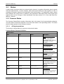
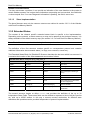
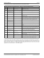
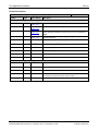
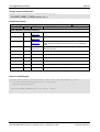
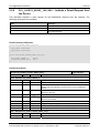
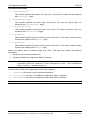
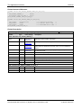
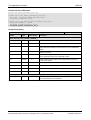
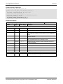
Revision History
Rev
Date
Name
Revisions
1
2005-07-26
RH
Created
2
2006-09-29
RH
First Draft
3
2007-05-15
RG/RH
Addition of 3 chapters “Fundamentals”,”Dual-Port Memory” and “Getting
Started”. A lot of additions and improvements in chapter “The Application
Interface” and “Status/Error Codes Overview”.
4
2007-11-05
RG
Review and changes in section technical data
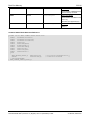
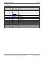
5
2008-03-04
RG
Review of technical data section.
Firmware/ stack version 2.0.10
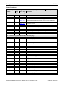
6
2008-05-30
HH/RG/ET
Firmware/ stack version V2.0.12
Reference to netX Dual-Port Memory Interface Manual Revision 5.
Section Common Status – All Implementation updated
A lot of small corrections.
7
2008-11-27
RG
Firmware/ stack version V2.1.19
Warmstart -> Set Configuration
Registration/unregistration packet marked as obsolete.
Removed TCP/IP task errors as described in separate documentation
Adapted error messages
Added section on task structure.
Changes in section ‘Object Modeling’
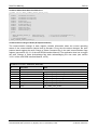
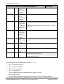
8
2010-05-04
RG
Firmware/ stack version V2.2.x.x
Device status added
Changes in Handshake, task structure, error codes
Section Technical Data: New: Support of DMA for PCI targets and support
of slot number for CIFX 50-DP
Section Technical Data: ‘Maximum number of total cyclic input data’
reduced from from 5760 bytes to 5712 bytes, because of the ‘Device
Status’ in the input data
Some small corrections
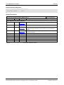
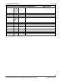
9
2010-07-02
RG/HH
Error corrections at sections Identity Object (Class Code: 0x01), TCP/IP
Interface Object (Class Code: 0xF5) and Ethernet Link Object (Class
Code: 0xF6)
Section Technical Data: IO Connection type: Cyclic, minimum 1 ms (2 ms
changed to 1 ms)
Reference to netX Dual-Port Memory Interface Manual Revision 9.
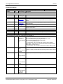
10
2010-12-10
RG
Firmware/ stack version V2.4.1.x
Added new section concerning DLR
Added DLR error descriptions
Added new section “Obtaining Diagnostic Information from connected
Slaves by sending an RCX_GET_SLAVE_CONN_INFO_REQ Packet”
Some corrections and additions
EtherNet/IP Scanner |
DOC050702API10EN | Revision 10 | English | 2010-12 | Released | Public
© Hilscher, 2006-2010
3/216
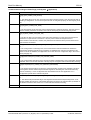
Table of Contents
1
Introduction.............................................................................................................................................5
1.1 Abstract ..........................................................................................................................................5
1.2 System Requirements....................................................................................................................5
1.3 Intended Audience .........................................................................................................................5
1.4 Specifications .................................................................................................................................6
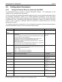
1.4.1 Technical Data .................................................................................................................................. 6
1.4.2 Protocol Task System........................................................................................................................ 7
1.4.3 Object Modeling ................................................................................................................................ 8
1.4.3.1
Identity Object (Class Code: 0x01) ..................................................................................... 8
1.4.3.2
Message Router Object (Class Code: 0x02) ...................................................................... 9
1.4.3.3
Assembly Object (Class Code: 0x04) ................................................................................. 9
1.4.3.4
TCP/IP Interface Object (Class Code: 0xF5) ...................................................................... 9
1.4.3.5
Ethernet Link Object (Class Code: 0xF6).......................................................................... 10
1.5 Terms, Abbreviations and Definitions ..........................................................................................11
1.6 References ...................................................................................................................................11
1.7 Legal Notes ..................................................................................................................................12
1.7.1
1.7.2
1.7.3
1.7.4
2
Copyright ......................................................................................................................................... 12
Important Notes............................................................................................................................... 12
Exclusion of Liability ........................................................................................................................ 13
Export .............................................................................................................................................. 13
Fundamentals .......................................................................................................................................14
2.1 General Access Mechanisms on netX Systems ..........................................................................14
2.2 Accessing the Protocol Stack by Programming the AP Task’s Queue........................................15
2.2.1 Getting the Receiver Task Handle of the Process Queue ............................................................... 15
2.2.2 Meaning of Source- and Destination-related Parameters................................................................ 15
2.3
Accessing the Protocol Stack via the Dual Port Memory Interface..............................................16
2.3.1 Communication via Mailboxes......................................................................................................... 16
2.3.2 Using Source and Destination Variables correctly........................................................................... 17
2.3.2.1
How to use ulDest for Addressing rcX and the netX Protocol Stack by the System and
Channel Mailbox ................................................................................................................................. 17
2.3.2.2
How to use ulSrc and ulSrcId ..................................................................................... 18
2.3.2.3
How to Route rcX Packets ................................................................................................ 19
2.3.3 Obtaining useful Information about the Communication Channel.................................................... 20
2.4
Client/Server Mechanism .............................................................................................................22
2.4.1 Application as Client ........................................................................................................................ 22
2.4.2 Application as Server ...................................................................................................................... 23
3
Dual-Port Memory ................................................................................................................................24
3.1 Cyclic Data (Input/Output Data) ...................................................................................................24
3.1.1 Input Process Data .......................................................................................................................... 25
3.1.2 Output Process Data ....................................................................................................................... 25
3.2
Acyclic Data (Mailboxes)..............................................................................................................26
3.2.1
3.2.2
3.2.3
3.2.4
3.2.5
3.2.6
3.3
General Structure of Messages or Packets for Non-Cyclic Data Exchange .................................... 27
Status & Error Codes ...................................................................................................................... 30
Differences between System and Channel Mailboxes .................................................................... 30
Send Mailbox................................................................................................................................... 30
Receive Mailbox .............................................................................................................................. 30
Channel Mailboxes (Details of Send and Receive Mailboxes) ........................................................ 31
Status ...........................................................................................................................................32
3.3.1 Common Status............................................................................................................................... 32
3.3.1.1
3.3.1.2
3.3.1.3
All Implementations ........................................................................................................... 32
Master Implementation...................................................................................................... 38
Slave Implementation........................................................................................................ 40
3.3.2 Extended Status .............................................................................................................................. 40
3.4
4
Control Block................................................................................................................................42
Getting started / Configuration ...........................................................................................................43
4.1 Overview about essential Functionality........................................................................................43
4.2 Configuration Parameters ............................................................................................................44
4.2.1 Using the Device Driver to write into the DPM................................................................................. 44
4.2.2 Write Access to the Dual-Port Memory............................................................................................ 45
EtherNet/IP Scanner |
DOC050702API10EN | Revision 10 | English | 2010-12 | Released | Public
© Hilscher, 2006-2010
Introduction
4/216
4.2.3 Using the configuration Tool SYCON.net ........................................................................................ 45
4.3
4.4
Task Structure of the EtherNet/IP Scanner Stack .......................................................................46
DLR ..............................................................................................................................................48
4.4.1 Fundamentals of DLR...................................................................................................................... 48
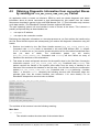
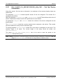
4.5 Obtaining Diagnostic Information from connected Slaves by sending an
RCX_GET_SLAVE_CONN_INFO_REQ Packet........................................................................................62
5
The Application Interface ....................................................................................................................65
5.1 The APM-Task .............................................................................................................................65
5.1.1
5.1.2
5.1.3
5.1.4
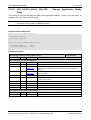
5.2
EIP_APM_WARMSTART_PRM_REQ/CNF - Set Warmstart Parameter .............................................. 66
EIP_APM_SET_CONFIGURATION_PRM_REQ/CNF - Set Configuration .......................................... 71
EIP_APM_REGISTER_APP_REQ/CNF - Register Application ......................................................... 76
EIP_APM_UNREGISTER_APP_REQ/CNF - Unregister Application.................................................. 78
The EipObject-Task .....................................................................................................................81
5.2.1 EIP_OBJECT_MR_REGISTER_REQ/CNF – Register a new Object at the Message Router............ 83
5.2.2 EIP_OBJECT_AS_REGISTER_REQ/CNF – Register a new Assembly Instance ............................. 88
5.2.3 EIP_OBJECT_ID_SETDEVICEINFO_REQ/CNF – Set the Device Information ............................... 94
5.2.4 EIP_OBJECT_CM_OPEN_CONN_REQ/CNF – Open a new Connection............................................ 99
5.2.5 EIP_OBJECT_CM_CONN_FAULT_IND/RES – Indicate a Connection Fault .................................. 112
5.2.6 EIP_OBJECT_CM_CLOSE_CONN_REQ/CNF – Close a Connection............................................... 114
5.2.7 EIP_OBJECT_SET_OUTPUT_REQ/CNF – Setting the Output Data............................................... 119
5.2.8 EIP_OBJECT_GET_INPUT_REQ/CNF – Getting the latest Input Data.......................................... 124
5.2.9 EIP_OBJECT_RESET_IND/RES – Indicate a Reset Request from the Device............................. 130
5.2.10 EIP_OBJECT_RESET_REQ/CNF – Request a Reset .................................................................... 131
5.2.11 EIP_OBJECT_TCP_STARTUP_CHANGE_IND/RES – Indicate Change of TCP Parameter ........... 134
5.2.12 EIP_OBJECT_CONNECTION_IND/RES – Indicate Change of Connection State.......................... 138
5.2.13 EIP_OBJECT_FAULT_IND/RES – Indicate a fatal Fault............................................................... 141
5.2.14 EIP_OBJECT_READY_REQ/CNF – Change Application Ready State ........................................... 143
5.2.15 EIP_OBJECT_REGISTER_CONNECTION_REQ/CNF – Register Connection at the Connection
Configuration Object ................................................................................................................................. 145
5.2.16 EIP_OBJECT_UNCONNECT_MESSAGE_REQ/CNF – Send an unconnected Message Request..... 157
5.2.17 EIP_OBJECT_OPEN_CL3_REQ/CNF – Open Class 3 Connection................................................ 161
5.2.18 EIP_OBJECT_CONNECT_MESSAGE_REQ/CNF – Send a Class 3 Message Request ................... 164
5.2.19 EIP_OBJECT_CLOSE_CL3_REQ/CNF – Close Class 3 Connection ............................................. 168
5.2.20 EIP_OBJECT_CL3_SERVICE_IND/RES – Indication of Class 3 Service ..................................... 170
5.3
The EipEncap-Task....................................................................................................................174
5.3.1
5.3.2
5.3.3
5.3.4
5.3.5
5.3.6
5.4
6
EIP_ENCAP_LISTIDENTITY_REQ/CNF – Issue a List Identity Request ..................................... 175
EIP_ENCAP_LISTIDENTITY_IND/RES – Indicate a List Identity Answer................................... 178
EIP_ENCAP_LISTSERVICE_REQ/CNF – Issue a List Service Request ....................................... 183
EIP_ENCAP_LISTSERVICE_IND/RES – Indicate a List Service Answer .................................... 187
EIP_ENCAP_LISTINTERFACE_REQ/CNF – Issue a List Interface Request................................. 191
EIP_ENCAP_LISTINTERFACE_IND/RES – Indicate a List Interface Answer .............................. 196
The TCP_IP-Task ......................................................................................................................200
Status/Error Codes Overview............................................................................................................201
6.1 Status/Error Codes EipObject-Task...........................................................................................201
6.1.1 Diagnostic Codes EipObject-Task ............................................................................................. 202
6.2
Status/Error Codes EipEncap-Task ...........................................................................................203
6.2.1 Diagnostic Codes EipEncap-Task ............................................................................................... 205
6.3
Status/Error Codes APM-Task...................................................................................................207
6.3.1 Diagnostic Codes APM-Task......................................................................................................... 208
6.4
6.5
7
Status/Error Codes Eip_DLR-Task..........................................................................................209
CIP General Error Codes ...........................................................................................................210
Appendix .............................................................................................................................................213
7.1 List of Tables..............................................................................................................................213
7.2 List of Figures.............................................................................................................................215
7.3 Contact .......................................................................................................................................216
EtherNet/IP Scanner |
DOC050702API10EN | Revision 10 | English | 2010-12 | Released | Public
© Hilscher, 2006-2010
Introduction
1
1.1
5/216
Introduction
Abstract
This manual describes the application interface of the Ethernet/IP-Scanner protocol stack, with the
aim to support and lead you during the integration process of the given stack into your own
Application.
Stack development is based on Hilscher’s Task Layer Reference Programming Model. This model
defines the general template used to create a task including a combination of appropriate functions
belonging to the same type of protocol layer. Furthermore, it defines of how different tasks have to
communicate with each other in order to exchange data between each communication layer. This
Reference Model is used by all programmers at Hilscher and shall be used by the developer when
writing an application task on top of the stack.
1.2
System Requirements
This software package has the following environmental system requirements:
netX-Chip as CPU hardware platform
Operating system for task scheduling required
1.3
Intended Audience
This manual is suitable for software developers with the following background:
Knowledge of the programming language C
Knowledge of the use of the real time operating system rcX
Knowledge of the Hilscher Task Layer Reference Model
Knowledge of the Common Industrial Protocol (CIPTM) Specification Volume 1
Knowledge of the Common Industrial Protocol (CIPTM) Specification Volume 2
Knowledge of the TCP/IP Protocol API
EtherNet/IP Scanner |
DOC050702API10EN | Revision 10 | English | 2010-12 | Released | Public
© Hilscher, 2006-2010
Introduction
1.4
6/216
Specifications
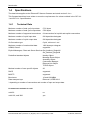
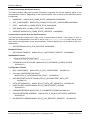
The data below applies to the Ethernet/IP Scanner firmware and stack version 2.4.x.x
This firmware/stack has been written to meet the requirements of a subset outlined in the CIP Vol.
1 and CIP Vol. 2 specifications.
1.4.1
Technical Data
Maximum number of total cyclic input data
5712 bytes
Maximum number of total cyclic output data
5760 bytes
Maximum number of supported connections
64 connections for implicit and explicit connections
Maximum number of cyclic input data
504 bytes/slave/telegram
Maximum number of cyclic output data
504 bytes/slave/telegram
IO Connection type
Cyclic, minimum 1 ms*
Maximum number of unscheduled data
1400 bytes per telegram
UCMM, Class 3
supported
Explicit Messages, Client and Server Services Get_Attribute_Single/All
Set_Attribute_Single/All
Predefined standard objects
Identity Object
Message Route Object
Assembly Object
Connection Manager
Ethernet Link Object
TCP/IP Object
Maximal number of user specific objects
20
DHCP
supported
BOOTP
supported
Baud rates
10 and 100 MBit/s
Data transport layer
Ethernet II, IEEE 802.3
* depending on number of connections and number of input and output data
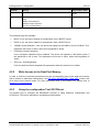
Firmware/stack available for netX
netX 50
no
netX 100, netX 500
yes
EtherNet/IP Scanner |
DOC050702API10EN | Revision 10 | English | 2010-12 | Released | Public
© Hilscher, 2006-2010
Introduction
7/216
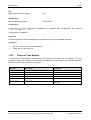
PCI
DMA Support for PCI targets
yes
Slot Number
Slot number supported for
CIFX 50-RE
Configuration
Configuration by tool SYCON.net (Download or exported two configuration files named
config.nxd and nwid.nxd).
Configuration by packets.
Diagnostic
Firmware supports common diagnostic in the dual-port-memory for loadable firmware.
Limitations
CIP Sync Services are not implemented.
TAGs are not supported yet
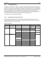
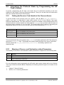
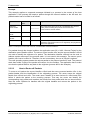
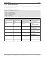
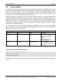
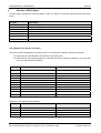
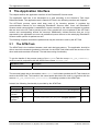
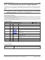
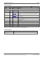
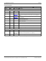
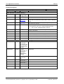
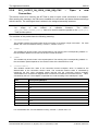
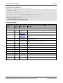
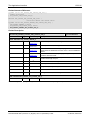
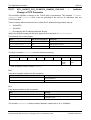
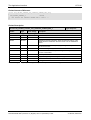
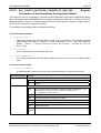
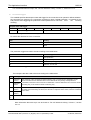
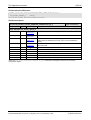
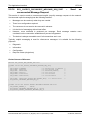
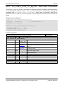
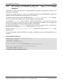
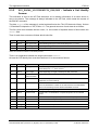
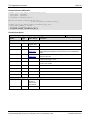
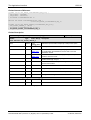
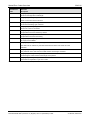
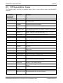
1.4.2
Protocol Task System
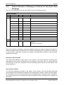
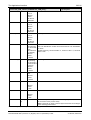
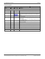
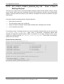
To manage the EtherNet/IP implementation five tasks are involved into the system. To send
packets to a task, the task main queue have to be identifier. For the identifier for the tasks and their
queues are the following naming conversion:
Task Name
Queue Name
Description
EIM_ENCAP_TASK
ENCAP_QUE
Encapsulation Layer
EIM_OBJECT_TASK
OBJECT_QUE
EtherNet/IP Objects
EIM_CL1_TASK
No queue
Class 1 communication
EIM_TCPUDP
EN_TCPUDP_QUE
TCP/IP Task
EIM_DLR
QUE_EIP_DLR
DLR Task
EIM_AP_TASK
EIPAPM_QUE
Dual Port Memory Interface or Application
Task Slave
Table 1: Names of Tasks in EtherNet/IP Firmware
EtherNet/IP Scanner |
DOC050702API10EN | Revision 10 | English | 2010-12 | Released | Public
© Hilscher, 2006-2010
Introduction
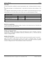
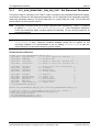
1.4.3
8/216
Object Modeling
The device is modeled as a collection of objects. Object modeling organizes related data and
procedures into one entity: the object. An object is a collection of related services and attributes.
Services are procedures an object performs. Attributes are characteristics of objects represented
by values or variables. Typically, attributes provide status information or govern the operation of an
object. An object's behaviour is an indication of how the object responds to particular events.
The following objects are present in the device and available from the link. The application is free
to define device specific objects and register them with the message router.
For details refer to the EtherNet/IP specification.
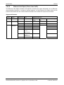
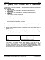
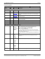
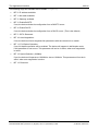
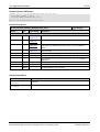
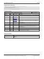
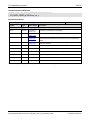
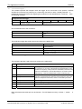
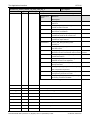
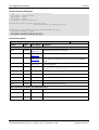
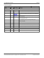
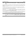
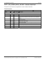
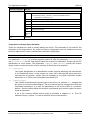
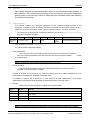
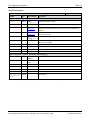
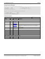
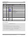
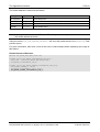
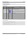
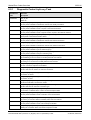
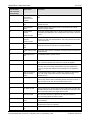
1.4.3.1
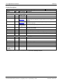
Identity Object (Class Code: 0x01)
The Identity Object provides identification and general information about the device. The first
instance identifies the whole device. It is used for electronic keying and by applications wishing to
determine what devices are on the network.
Supported Features
Instance
0
1
Name
Class
Instance
Attributes
Attribute ID
Name
Supported Services
Get Attribute
Get Attribute
Single
All
Yes
1
Revision
Yes
2
Max. Instance
Yes
5
Optional service list
(contains reset service)
Yes
No
6
Max. Class Attrib.
Yes
Yes
7
Max. Instance Attrib.
Yes
1
Vendor ID
Yes
2
Device Type
Yes
3
Product Code
Yes
4
Major Revision
Yes
Minor Revision
Yes
5
Status
Yes
6
Serial Number
Yes
7
Product Name
Yes
8
State
Yes
9
Conf. Consist. Value
Yes
10
Heart Interval
No
Yes
Table 2: Identity Object Supported Features
EtherNet/IP Scanner |
DOC050702API10EN | Revision 10 | English | 2010-12 | Released | Public
© Hilscher, 2006-2010
Introduction
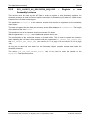
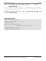
1.4.3.2
9/216
Message Router Object (Class Code: 0x02)
The Message Router Object provides a messaging connection point through which a client may
address a service to any object class or instance residing in the physical device.
Supported Features
There are no services supported by the Message Router Object.
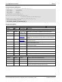
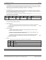
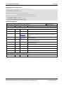
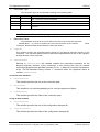
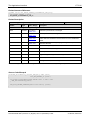
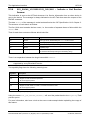
1.4.3.3
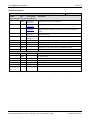
Assembly Object (Class Code: 0x04)
The Assembly Object binds attributes of multiple objects, which allows data to or from each object
to be sent or received over a single connection. Assembly Objects can be used to bind input data
or output data. The terms ”input” and ”output” are defined from the network’s point of view. An
output will produce data on the network and an input will consume data from the network.
Supported Features
Instance
0
1-x
Name
Attribute ID
Class
Instance
Attributes
Name
1
Revision
2
Max. Instance
3
Data
4
Size
Supported Services
Get Attribute Single
Set Attribute Single
Yes
No
No
Yes
Yes
No
Table 3: Assembly Object Supported Features
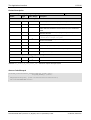
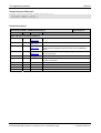
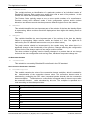
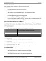
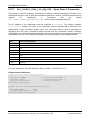
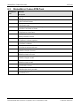
1.4.3.4
TCP/IP Interface Object (Class Code: 0xF5)
The TCP/IP Interface Object provides the mechanism to configure a device’s TCP/IP network
interface. Examples of configurable items include the device’s IP Address, Network Mask, and
Gateway Address.
Supported Features
Instance Name
0
1
Class
Instance
Attributes
Attribute ID
Name
1
Revision
2
Max. Instance
Supported Services
Get
Get
Set Attribute
Attribute
Attribute
Single
Single
All
Yes
No
No
No
Yes
Yes
1
Status
2
Configuration Capability
No
No
3
Configuration Control
Yes
4
Physical Link Object
No
5
Interface Configuration
No
6
Host Name
Yes
Table 4: TCP/IP Interface Object Supported Features
EtherNet/IP Scanner |
DOC050702API10EN | Revision 10 | English | 2010-12 | Released | Public
© Hilscher, 2006-2010
Introduction
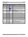
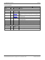
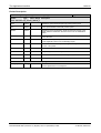
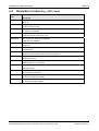
1.4.3.5
10/216
Ethernet Link Object (Class Code: 0xF6)
The Ethernet Link Object maintains link-specific counters and status information for an Ethernet
communications interface. A request to access instance 1 of the Ethernet Link Object refers to the
instance associated with the communications interface over which the request was received.
Supported Features
Instance
0
1
Name
Class
Instance
Attributes
Attribute ID
Name
Supported Services
Get Attribute
Get Attribute
Single
All
Set Attribute Single
1
Revision
Yes
No
No
2
Max. Instance
Yes
No
No
1
Interface Speed
Yes
Yes
No
2
Interface Flags
Yes
No
3
Physical Address
Yes
No
4
Interface Counters No
No
(not yet
implemented)
5
Media Counters
No
No
Yes
Yes
(not yet
implemented)
6
Interface Control
Table 5: Ethernet Link Object Supported Features
EtherNet/IP Scanner |
DOC050702API10EN | Revision 10 | English | 2010-12 | Released | Public
© Hilscher, 2006-2010
Introduction
1.5
11/216
Terms, Abbreviations and Definitions
Term
Description
ACD
Address Conflict Detection
AP
Application on top of the Stack
API
Actual Packet Interval
AS
Assembly Object
CC
Connection Configuration Object
CIP
Common Industrial Protocol
CM
Connection Manager
DLR
Device Level Ring (i.e. ring topology on device level)
EIM
Ethernet/IP Scanner
EIP
Ethernet/IP
ENCAP
Encapsulation Layer
ID
Identity Object
IP
Internet Protocol
MR
Message Router Object
RPI
Requested Packet Interval
UCMM
Unconnected Message Manager
Table 6: Terms, Abbreviations and Definitions
All variables, parameters, and data used in this manual have the LSB/MSB (“Intel”) data
representation. This corresponds to the convention of the Microsoft C Compiler.
1.6
References
This document is based on the following specifications:
Nr.
Reference
1
Hilscher Gesellschaft für Systemautomation mbH: Dual-Port Memory Interface Manual - netX based products.
Revision 9, english, 2010
2
TCP/IP Protocol Interface Manual, Hilscher GmbH
3
Common Industrial Protocol (CIPTM) Specification Volume 1
4
Common Industrial Protocol (CIPTM) Specification Volume 2
Table 7: References
EtherNet/IP Scanner |
DOC050702API10EN | Revision 10 | English | 2010-12 | Released | Public
© Hilscher, 2006-2010
Introduction
1.7
1.7.1
©
12/216
Legal Notes
Copyright
2006-2010 Hilscher Gesellschaft für Systemautomation mbH
All rights reserved.
The images, photographs and texts in the accompanying material (user manual, accompanying
texts, documentation, etc.) are protected by German and international copyright law as well as
international trade and protection provisions. You are not authorized to duplicate these in whole or
in part using technical or mechanical methods (printing, photocopying or other methods), to
manipulate or transfer using electronic systems without prior written consent. You are not permitted
to make changes to copyright notices, markings, trademarks or ownership declarations. The
included diagrams do not take the patent situation into account. The company names and product
descriptions included in this document may be trademarks or brands of the respective owners and
may be trademarked or patented. Any form of further use requires the explicit consent of the
respective rights owner.
1.7.2
Important Notes
The user manual, accompanying texts and the documentation were created for the use of the
products by qualified experts, however, errors cannot be ruled out. For this reason, no guarantee
can be made and neither juristic responsibility for erroneous information nor any liability can be
assumed. Descriptions, accompanying texts and documentation included in the user manual do
not present a guarantee nor any information about proper use as stipulated in the contract or a
warranted feature. It cannot be ruled out that the user manual, the accompanying texts and the
documentation do not correspond exactly to the described features, standards or other data of the
delivered product. No warranty or guarantee regarding the correctness or accuracy of the
information is assumed.
We reserve the right to change our products and their specification as well as related user
manuals, accompanying texts and documentation at all times and without advance notice, without
obligation to report the change. Changes will be included in future manuals and do not constitute
any obligations. There is no entitlement to revisions of delivered documents. The manual delivered
with the product applies.
Hilscher Gesellschaft für Systemautomation mbH is not liable under any circumstances for direct,
indirect, incidental or follow-on damage or loss of earnings resulting from the use of the information
contained in this publication.
EtherNet/IP Scanner |
DOC050702API10EN | Revision 10 | English | 2010-12 | Released | Public
© Hilscher, 2006-2010
Introduction
1.7.3
13/216
Exclusion of Liability
The software was produced and tested with utmost care by Hilscher Gesellschaft für
Systemautomation mbH and is made available as is. No warranty can be assumed for the
performance and flawlessness of the software for all usage conditions and cases and for the
results produced when utilized by the user. Liability for any damages that may result from the use
of the hardware or software or related documents, is limited to cases of intent or grossly negligent
violation of significant contractual obligations. Indemnity claims for the violation of significant
contractual obligations are limited to damages that are foreseeable and typical for this type of
contract.
It is strictly prohibited to use the software in the following areas:
for military purposes or in weapon systems;
for the design, construction, maintenance or operation of nuclear facilities;
in air traffic control systems, air traffic or air traffic communication systems;
in life support systems;
in systems in which failures in the software could lead to personal injury or injuries leading to
death.
We inform you that the software was not developed for use in dangerous environments requiring
fail-proof control mechanisms. Use of the software in such an environment occurs at your own risk.
No liability is assumed for damages or losses due to unauthorized use.
1.7.4
Export
The delivered product (including the technical data) is subject to export or import laws as well as
the associated regulations of different counters, in particular those of Germany and the USA. The
software may not be exported to countries where this is prohibited by the United States Export
Administration Act and its additional provisions. You are obligated to comply with the regulations at
your personal responsibility. We wish to inform you that you may require permission from state
authorities to export, re-export or import the product.
EtherNet/IP Scanner |
DOC050702API10EN | Revision 10 | English | 2010-12 | Released | Public
© Hilscher, 2006-2010
Fundamentals
2
14/216
Fundamentals
2.1
General Access Mechanisms on netX Systems
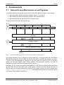
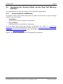
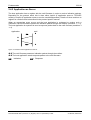
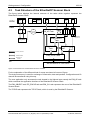
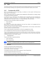
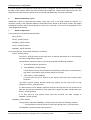
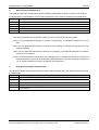
This chapter explains the possible ways to access a Protocol Stack running on a netX system :
1. By accessing the Dual Port Memory Interface directly or via a driver.
2. By accessing the Dual Port Memory Interface via a shared memory.
3. By interfacing with the Stack Task of the Protocol Stack.
The picture below visualizes these three ways:
1
2
(Extended) Status Block
Send Mailbox
Reveive Mailbox
Output Data Image
Input Data Image
AP Task
3
Fieldbus Task(s)
Network Abstraction Layer
Network
Figure 1 - The three different Ways to access a Protocol Stack running on a netX System
This chapter explains how to program the stack (alternative 3) correctly while the next chapter
describes accessing the protocol stack via the dual-port memory interface according to alternative
1 (and 2, if the user application is executed on the netX chip in the context of the rcX operating
system and uses the shared DPM). Finally, chapter “The Application Interface” on page 65
describes the entire interface to the protocol stack in detail.
Depending on you choose the stack-oriented approach or the Dual Port Memory-based approach,
you will need either the information given in this chapter or those of the next chapter to be able to
work with the set of functions described in chapter 5. All of those functions use the four parameters
ulDest, ulSrc, ulDestId and ulSrcId. This chapter and the next one inform about how
to work with these important parameters.
EtherNet/IP Scanner |
DOC050702API10EN | Revision 10 | English | 2010-12 | Released | Public
© Hilscher, 2006-2010
Fundamentals
2.2
15/216
Accessing the Protocol Stack by Programming the AP
Task’s Queue
In general, programming the AP task or the stack has to be performed according to the rules
explained in the Hilscher Task Layer Reference Manual. There you can also find more information
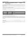
about the variables discussed in the following.
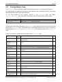
2.2.1
Getting the Receiver Task Handle of the Process Queue
To get the handle of the process queue of a specific task the Macro TLR_QUE_IDENTIFY()
needs to be used. It is described in detail within section 10.1.9.3 of the Hilscher Task Layer
Reference Model Manual. This macro delivers a pointer to the handle of the intended queue to be
accessed (which is returned within the third parameter, phQue), if you provide it with the name of
the queue (and an instance of your own task). The correct ASCII-queue names for accessing the
desired task which you have to use as current value for the first parameter (pszIdn) is
ASCII Queue name
Description
"OBJECT_QUE”
Name of the EipObject-Task process queue
"ENCAP_QUE”
Name of the EipEncap-Task process queue
“QUE_EIP_CL1”
Name of the CL1-Task process queue
Table 8: Names of Queues in EtherNet/IP Firmware
The returned handle has to be used as value ulDest in all initiator packets the AP-Task intends to
send to the EipObject-Task . This handle is the same handle that has to be used in conjunction
with the macros like TLR_QUE_SENDPACKET_FIFO/LIFO() for sending a packet to the
respective task.
2.2.2
Meaning of Source- and Destination-related Parameters
The meaning of the source- and destination-related parameters is explained in the following table:
Variable
Meaning
ulDest
Application mailbox used for confirmation
ulSrc
Queue handle returned by TLR_QUE_IDENTIFY() as described above.
ulSrcId
Used for addressing at a lower level
Table 9: Meaning of Source- and Destination-related Parameters.
For more information about programming the AP task’s stack queue, please refer to the Hilscher
Task Layer Reference Model Manual. Especially the following sections might be of interest in this
context:
1.
Chapter 7 “Queue-Packets”
2.
Section 10.1.9 “Queuing Mechanism”
EtherNet/IP Scanner |
DOC050702API10EN | Revision 10 | English | 2010-12 | Released | Public
© Hilscher, 2006-2010
Fundamentals
2.3
16/216
Accessing the Protocol Stack via the Dual Port Memory
Interface
This chapter defines the application interface of the EtherNet/IP-Adapter Stack.
2.3.1
Communication via Mailboxes
The mailbox of each communication channel has two areas that are used for non-cyclic message
transfer to and from the netX.
Send Mailbox
Packet transfer from host system to netX firmware
Receive Mailbox
Packet transfer from netX firmware to host system
For more details about acyclic data transfer via mailboxes, see section 3.2. Acyclic Data
(Mailboxes) in this context, is described in detail in section 3.2.1 “General Structure of Messages or
Packets for Non-Cyclic Data Exchange” while the possible codes that may appear are listed in
section 3.2.2. “Status & Error Codes”.
However, this section concentrates on correct addressing the mailboxes.
EtherNet/IP Scanner |
DOC050702API10EN | Revision 10 | English | 2010-12 | Released | Public
© Hilscher, 2006-2010
Fundamentals
2.3.2
2.3.2.1
17/216
Using Source and Destination Variables correctly
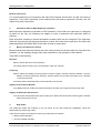
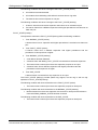
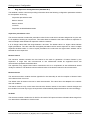
How to use ulDest for Addressing rcX and the netX Protocol Stack by the
System and Channel Mailbox
System
Mailbox
Channel 0
Mainbox
ulDest = 0x02
ulDest = 0x01
ulDest = 0x00
ulDest = 0x20
ulDest = 0x02
ulDest = 0x01
ulDest = 0x00
ulDest = 0x20
ulDest = 0x02
ulDest = 0x01
ulDest = 0x00
ulDest = 0x20
The preferred way to address the netX operating system rcX is through the system mailbox; the
preferred way to address a protocol stack is through its channel mailbox. All mailboxes, however,
have a mechanism to route packets to a communication channel or the system channel,
respectively. Therefore, the destination identifier ulDest in a packet header has to be filled in
according to the targeted receiver. See the following example:
Channel 1
Mailbox
netX OS
rcX
AP Task 1
AP Task 2
Figure 2: Use of ulDest in Channel and System Mailbox
For use in the destination queue handle, the tasks have been assigned to hexadecimal numerical
values as described in the following table:
ulDest
Description
0x00000000
Packet is passed to the netX operating system rcX
0x00000001
Packet is passed to communication channel 0
0x00000002
Packet is passed to communication channel 1
0x00000003
Packet is passed to communication channel 2
0x00000004
Packet is passed to communication channel 3
0x00000020
Packet is passed to communication channel of the mailbox
else
Reserved, do not use
Table 10: Meaning of Destination-Parameter ulDest.Parameters.
The figure and the table above both show the use of the destination identifier ulDest.
A remark on the special channel identifier 0x00000020 (= Channel Token). The Channel Token is
valid for any mailbox. That way the application uses the same identifier for all packets without
actually knowing which mailbox or communication channel is applied. The packet stays 'local'. The
EtherNet/IP Scanner |
DOC050702API10EN | Revision 10 | English | 2010-12 | Released | Public
© Hilscher, 2006-2010
Fundamentals
18/216
system mailbox is a little bit different, because it is used to communicate to the netX operating
system rcX. The rcX has its own range of valid commands codes and differs from a communication
channel.
Unless there is a reply packet, the netX operating system returns it to the same mailbox the
request packet went through. Consequently, the host application has to return its reply packet to
the mailbox the request was received from.
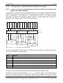
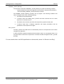
2.3.2.2
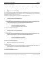
How to use ulSrc and ulSrcId
Generally, a netX protocol stack can be addressed through its communication channel mailbox.
The example below shows how a host application addresses a protocol stack running in the
context of a netX chip. The application is identified by a number (#444 in this example). The
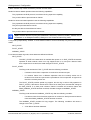
application consists of three processes identified by the numbers #11, #22 and #33. These
processes communicate through the channel mailbox with the AP task of the protocol stack. Have
a look at the following figure:
Process #33
Process #22
Process #11
Application #444
Channel
Mainbox
netX Protocol stack
AP Task 1
Figure 3: Using ulSrc and ulSrcId
EtherNet/IP Scanner |
DOC050702API10EN | Revision 10 | English | 2010-12 | Released | Public
© Hilscher, 2006-2010
Fundamentals
19/216
Example:
This example applies to command messages initiated by a process in the context of the host
application. If the process #22 sends a packet through the channel mailbox to the AP task, the
packet header has to be filled in as follows:
Object
Variable
Numeric Value Explanation
Name
Destination
Queue Handle
ulDest
(0x00000020
)
This value needs always to be set to 0x00000020 (the channel
token) when accessing the protocol stack via the local
communication channel mailbox.
Source Queue
Handle
ulSrc
= 444
Denotes the host application (#444).
Destination
Identifier
ulDestId
= 0
In this example, it is not necessary to use the destination identifier.
Source Identifier
ulSrcId
= 22
Denotes the process number of the process within the host
application and needs therefore to be supplied by the programmer
of the host application.
= 32
Table 11: Example for correct Use of Source- and Destination-related Parameters.:
For packets through the channel mailbox, the application uses 32 (= 0x20, Channel Token) for the
destination queue handler ulDest. The source queue handler ulSrc and the source identifier ulSrcId
are used to identify the originator of a packet. The destination identifier ulDestId can be used to
address certain resources in the protocol stack. It is not used in this example. The source queue
handler ulSrc has to be filled in. Therefore, its use is mandatory; the use of ulSrcId is optional.
The netX operating system passes the request packet to the protocol stack's AP task. The protocol
stack then builds a reply to the packet and returns it to the mailbox. The application has to make
sure that the packet finds its way back to the originator (process #22 in the example).
2.3.2.3
How to Route rcX Packets
To route an rcX packet the source identifier ulSrcId and the source queues handler ulSrc in the
packet header hold the identification of the originating process. The router saves the original
handle from ulSrcId and ulSrc. The router uses a handle of its own choices for ulSrcId and ulSrc
before it sends the packet to the receiving process. That way the router can identify the
corresponding reply packet and matches the handle from that packet with the one stored earlier.
Now the router replaces its handles with the original handles and returns the packet to the
originating process.
EtherNet/IP Scanner |
DOC050702API10EN | Revision 10 | English | 2010-12 | Released | Public
© Hilscher, 2006-2010
Fundamentals
2.3.3
Obtaining
Channel
20/216
useful
Information
about
the
Communication
A communication channel represents a part of the Dual Port Memory and usually consists of the
following elements:
• Output Data Image
is used to transfer cyclic process data to the network (normal or high-priority)
• Input Data Image
is used to transfer cyclic process data from the network (normal or high-priority)
• Send Mailbox
is used to transfer non-cyclic data to the netX
• Receive Mailbox
is used to transfer non-cyclic data from the netX
• Control Block
allows the host system to control certain channel functions
• Common Status Block
holds information common to all protocol stacks
• Extended Status Block
holds protocol specific network status information
This section describes a procedure how to obtain useful information for accessing the
communication channel(s) of your netX device and to check if it is ready for correct operation.
Proceed as follows:
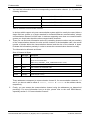
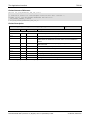
1.
Start with reading the channel information block within the system channel (usually starting at
address 0x0030).
2.
Then you should check the hardware assembly options of your netX device. They are
located within the system information block following offset 0x0010 and stored as data type
UINT16. The following table explains the relationship between the offsets and the
corresponding xC Ports of the netX device:
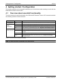
0x0010
Hardware Assembly Options for xC Port[0]
0x0012
Hardware Assembly Options for xC Port[1]
0x0014
Hardware Assembly Options for xC Port[2]
0x0016
Hardware Assembly Options for xC Port[3]
Table 12: Hardware Assembly Options for xC Ports
Check each of the hardware assembly options whether its value has been set to
RCX_HW_ASSEMBLY_ETHERNET = 0x0080. If true, this denotes that this xCPort is suitable
for running the EtherNet/IP protocol stack. Otherwise, this port is designed for another
communication protocol. In most cases, xC Port[2] will be used for field bus systems, while
xC Port[0] and xC Port[1] are normally used for Ethernet communication.
EtherNet/IP Scanner |
DOC050702API10EN | Revision 10 | English | 2010-12 | Released | Public
© Hilscher, 2006-2010
Fundamentals
3.
21/216
You can find information about the corresponding communication channel (0…3) under the
following addresses:
0x0050
Communication Channel 0
0x0060
Communication Channel 1
0x0070
Communication Channel 2
0x0080
Communication Channel 3
Table 13: Addresses of Communication Channels
In devices which support only one communication system which is usually the case (either a
single field bus system or a single standard for Industrial-Ethernet communication), always
communication channel 0 will be used. In devices supporting more than one communication
system you should also check the other communication channels.
4.
There you can find such information as the ID (containing channel number and port number)
of the communication channel, the size and the location of the handshake cells, the overall
number of blocks within the communication channel and the size of the channel in bytes.
Evaluate this information precisely in order to access the communication channel correctly.
The information is delivered as follows:
Size of Channel in Bytes
Address
Data Type
Description
0x0050
UINT8
Channel Type = COMMUNICATION
(must have the fixed value
define RCX_CHANNEL_TYPE_COMMUNICATION = 0x05)
0x0051
UINT8
ID (Channel Number, Port Number)
0x0052
UINT8
Size / Position Of Handshake Cells
0x0053
UINT8
Total Number Of Blocks Of This Channel
0x0054
UINT32
Size Of Channel In Bytes
0x0058
UINT8[8]
Reserved (set to zero)
Table 14: Information related to Communication Channel
These addresses correspond to communication channel 0, for communication channels 1, 2
and 3 you have to add an offset of 0x0010, 0x0020 or 0x0030 to the address values,
respectively.
5.
Finally, you can access the communication channel using the addresses you determined
previously. For more information how to do this, please refer to the netX DPM Manual,
especially section 3.2 “Communication Channel".
EtherNet/IP Scanner |
DOC050702API10EN | Revision 10 | English | 2010-12 | Released | Public
© Hilscher, 2006-2010
Fundamentals
2.4
22/216
Client/Server Mechanism
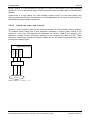
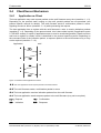
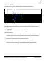
2.4.1
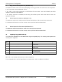
Application as Client
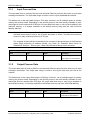
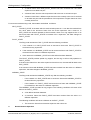
The host application may send request packets to the netX firmware at any time (transition 1 Ö 2).
Depending on the protocol stack running on the netX, parallel packets are not permitted (see
protocol specific manual for details). The netX firmware sends a confirmation packet in return,
signaling success or failure (transition 3 Ö 4) while processing the request.
The host application has to register with the netX firmware in order to receive indication packets
(transition 5 Ö 6). Depending on the protocol stack, this is done either implicit (if application opens
a TCP/UDP socket) or explicit (if application wants to receive unsolicited packets). Details on when
and how to register for certain events is described in the protocol specific manual. Depending on
the command code of the indication packet, a response packet to the netX firmware may or may
not be required (transition 7 Ö 8).
Application
netX
n
o
p
q
r
s
t
u
Figure 4: Transition Chart Application as Client
n o The host application sends request packets to the netX firmware.
p q The netX firmware sends a confirmation packet in return.
r s The host application receives indication packets from the netX firmware.
t u The host application sends response packet to the netX firmware (may not be required).
Request
Confirmation
Indication
Response
EtherNet/IP Scanner |
DOC050702API10EN | Revision 10 | English | 2010-12 | Released | Public
© Hilscher, 2006-2010
Fundamentals
23/216
2.4.2 Application as Server
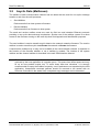
The host application has to register with the netX firmware in order to receive indication packets.
Depending on the protocol stack, this is done either implicit (if application opens a TCP/UDP
socket) or explicit (if application wants to receive unsolicited packets). Details on when and how to
register for certain events is described in the protocol specific manual.
When an appropriate event occurs and the host application is registered to receive such a
notification, the netX firmware passes an indication packet through the mailbox (transition 1 Ö 2).
The host application is expected to send a response packet back to the netX firmware (transition 3
Ö 4).
Application
netX
n
o
p
q
Figure 5: Transition Chart Application as Server
n o The netX firmware passes an indication packet through the mailbox.
p q The host application sends response packet to the netX firmware.
Indication
Response
EtherNet/IP Scanner |
DOC050702API10EN | Revision 10 | English | 2010-12 | Released | Public
© Hilscher, 2006-2010
Dual-Port Memory
3
24/216
Dual-Port Memory
All data in the dual-port memory is structured in blocks. According to their functions, these blocks
use different data transfer mechanisms. For example, data transfer through mailboxes uses a
synchronized handshake mechanism between host system and netX firmware. The same is true
for IO data images, when a buffered handshake mode is configured. Other blocks, like the status
block, are read by the host application and use no synchronization mechanism.
Types of blocks in the dual-port memory are outlined below:
Mailbox
transfer non-cyclic messages or packages with a header for routing information
Data Area
holds the process image for cyclic I/O data or user defined data structures
Control Block
is used to signal application related state to the netX firmware
Status Block
holds information regarding the current network state
Change of State
collection of flags that initiate execution of certain commands or signal a change of state
Note:
3.1
Connections for cyclic I/O are called implicit connections in EtherNet/IP.
Cyclic Data (Input/Output Data)
The input block holds the process data image received from the network whereas the output block
holds data sent to the network
For the controlled / buffered mode, the protocol stack updates the process data in the internal input
buffer for each valid bus cycle. Each IO block uses handshake bits for access synchronization.
Input and output data block handshake operates independently from each other. When the
application toggles the input handshake bit, the protocol stack copies the data from the internal
buffer into the input data image of the dual-port memory. Now the application can copy data from
the dual-port memory and then give control back to the protocol stack by toggling the appropriate
input handshake bit. When the application/driver toggles the output handshake bit, the protocol
stack copies the data from the output data image of the dual-port memory into the internal buffer.
From there the data is transferred to the network. The protocol stack toggles the handshake bits
back, indicating to the application that the transfer is finished and a new data exchange cycle may
start. This mode guarantees data consistency over both input and output area.
EtherNet/IP Scanner |
DOC050702API10EN | Revision 10 | English | 2010-12 | Released | Public
© Hilscher, 2006-2010
Dual-Port Memory
3.1.1
25/216
Input Process Data
The input data block is used by field bus and industrial Ethernet protocols that utilize a cyclic data
exchange mechanism. The input data image is used to receive cyclic data from the network.
The default size of the input data image is 5760 byte. However, not all available space is actually
used by the protocol stack. Depending on the specific protocol, the area actually available for user
data might be much smaller than 5760 byte. An input data block may or may not be available in the
dual-port memory. It is always available in the default memory map (see the netX Dual-Port
Memory Manual).
Note: 48 byte are used for status information (16 byte for list of configured slaves, 16 byte for list of
activated slaves and 16 byte for list of slaves with faults or errors). Therefore the maximum
amount of really usable input data is 5712 byte.
The contents of these 48 byte is identical to the contents of the second part of the Extended
Status Block beginning at address 0x0100, see Table 25: Extended Status Block for
EtherNet/IP Scanner – Second part (State Field Definition Block) of this document.
Input Data Image
Offset
Type
Name
Description
0x2680
UINT8
abPd0Input[5760]
Input Data Image
Cyclic Data From The Network
Table 15: Input Data Image
3.1.2
Output Process Data
The output data block is used by field bus and industrial Ethernet protocols that utilize a cyclic data
exchange mechanism. The output data Image is used to send cyclic data from the host to the
network.
The default size of the output data image is 5760 byte. However, not all available space is actually
used by the protocol stack. Depending on the specific protocol, the area actually available for user
data might be much smaller than 5760 byte. An output data block may or may not be available in
the dual-port memory. It is always available in the default memory map (see netX DPM Manual).
Output Data Image
Offset
Type
Name
Description
0x1000
UINT8
abPd0Output[5760]
Output Data Image
Cyclic Data To The Network
Table 16: Output Data Image
EtherNet/IP Scanner |
DOC050702API10EN | Revision 10 | English | 2010-12 | Released | Public
© Hilscher, 2006-2010
Dual-Port Memory
3.2
26/216
Acyclic Data (Mailboxes)
The mailbox of each communication channel has two areas that are used for non-cyclic message
transfer to and from the netX processor.
Send Mailbox
Packet transfer from host system to firmware
Receive Mailbox
Packet transfer from firmware to host system
The send and receive mailbox areas are used by field bus and industrial Ethernet protocols
providing a non-cyclic data exchange mechanism. Another use of the mailbox system is to allow
access to the firmware running on the netX chip itself for diagnostic and identification purposes.
The send mailbox is used to transfer acyclic data to the network or to the firmware. The receive
mailbox is used to transfer acyclic data from the network or from the firmware.
A send/receive mailbox may or may not be available in the communication channel. It depends on
the function of the firmware whether or not a mailbox is needed. The location of the system
mailbox and the channel mailbox is described in the netX DPM Interface Manual.
Note: Each mailbox can hold one packet at a time. The netX firmware stores packets that are not
retrieved by the host application in a packet queue. This queue has limited space and may
fill up so new packets maybe lost. To avoid these data loss situations, it is strongly
recommended to empty the mailbox frequently, even if packets are not expected by the host
application. Unexpected command packets should be returned to the sender with an
Unknown Command in the status field; unexpected reply messages can be discarded.
EtherNet/IP Scanner |
DOC050702API10EN | Revision 10 | English | 2010-12 | Released | Public
© Hilscher, 2006-2010
Dual-Port Memory
3.2.1
27/216
General Structure of Messages or Packets for Non-Cyclic Data
Exchange
The non-cyclic packets through the netX mailbox have the following structure:
Structure Information
Area
Variable
Head
Structure Information
Data
Type
Value / Range
Description
ulDest
UINT32
Destination Queue Handle
ulSrc
UINT32
Source Queue Handle
ulDestId
UINT32
Destination Queue Reference
ulSrcId
UINT32
Source Queue Reference
ulLen
UINT32
Packet Data Length (In Bytes)
ulId
UINT32
Packet Identification As Unique Number
ulSta
UINT32
Status / Error Code
ulCmd
UINT32
Command / Response
ulExt
UINT32
Extension Flags
ulRout
UINT32
Routing Information
Structure Information
…
…
User Data
Specific To The Command
Table 17: General Structure of Packets for non-cyclic Data Exchange.
Some of the fields are mandatory; some are conditional; others are optional. However, the size of a
packet is always at least 10 double-words or 40 bytes. Depending on the command, a packet may
or may not have a data field. If present, the content of the data field is specific to the command,
respectively the reply.
Destination Queue Handle
The ulDest field identifies a task queue in the context of the netX firmware. The task queue
represents the final receiver of the packet and is assigned to a protocol stack. The ulDest field has
to be filled out in any case. Otherwise, the netX operating system cannot route the packet. This
field is mandatory.
Source Queue Handle
The ulSrc field identifies the sender of the packet. In the context of the netX firmware (inter-task
communication) this field holds the identifier of the sending task. Usually, a driver uses this field for
its own handle, but it can hold any handle of the sending process. Using this field is mandatory.
The receiving task does not evaluate this field and passes it back unchanged to the originator of
the packet.
EtherNet/IP Scanner |
DOC050702API10EN | Revision 10 | English | 2010-12 | Released | Public
© Hilscher, 2006-2010
Dual-Port Memory
28/216
Destination Identifier
The ulDestId field identifies the destination of an unsolicited packet from the netX firmware to the
host system. It can hold any handle that helps to identify the receiver. Therefore, its use is
mandatory for unsolicited packets. The receiver of unsolicited packets has to register for this.
Source Identifier
The ulSrcId field identifies the originator of a packet. This field is used by a host application, which
passes a packet from an external process to an internal netX task. The ulSrcId field holds the
handle of the external process. When netX operating system returns the packet, the application
can identify the packet and returns it to the originating process. The receiving task on the netX
does not evaluate this field and passes it back unchanged. For inter-task communication, this field
is not used.
Length of Data Field
The ulLen field holds the size of the data field in bytes. It defines the total size of the packet’s
payload that follows the packet’s header. The size of the header is not included in ulLen. So the
total size of a packet is the size from ulLen plus the size of packet’s header. Depending on the
command, a data field may or may not be present in a packet. If no data field is included, the
length field is set to zero.
Identifier
The ulId field is used to identify a specific packet among others of the same kind. That way the
application or driver can match a specific reply or confirmation packet to a previous request packet.
The receiving task does not change this field and passes it back to the originator of the packet. Its
use is optional in most of the cases. However, it is mandatory for sequenced packets.
Example: Downloading big amounts of data that does not fit into a single packet. For a sequence
of packets the identifier field is incremented by one for every new packet.
Status / Error Code
The ulSta field is used in response or confirmation packets. It informs the originator of the packet
about success or failure of the execution of the command. The field may be also used to hold
status information in a request packet.
Command / Response
The ulCmd field holds the command code or the response code, respectively. The
command/response is specific to the receiving task. If a task is not able to execute certain
commands, it will return the packet with an error indication. A command is always even (the least
significant bit is zero). In the response packet, the command code is incremented by one indicating
a confirmation to the request packet.
EtherNet/IP Scanner |
DOC050702API10EN | Revision 10 | English | 2010-12 | Released | Public
© Hilscher, 2006-2010
Dual-Port Memory
29/216
Extension Flags
The extension field ulExt is used for controlling packets that are sent in a sequenced manner. The
extension field indicates the first, last or a packet of a sequence. If sequencing is not required, the
extension field is not used and set to zero.
Routing Information
The ulRout field is used internally by the netX firmware only. It has no meaning to a driver type
application and therefore set to zero.
User Data Field
This field contains data related to the command specified in ulCmd field. Depending on the
command, a packet may or may not have a data field. The length of the data field is given in the
ulLen field.
EtherNet/IP Scanner |
DOC050702API10EN | Revision 10 | English | 2010-12 | Released | Public
© Hilscher, 2006-2010
Dual-Port Memory
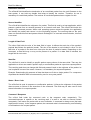
3.2.2
30/216
Status & Error Codes
The following status and error codes from the operating system rcX can be returned in ulSta: List
of codes see manual named netX Dual-Port Memory Interface.
3.2.3
Differences between System and Channel Mailboxes
The mailbox system on netX provides a non-cyclic data transfer channel for field bus and industrial
Ethernet protocols. Another use of the mailbox is allowing access to the firmware running on the
netX chip itself for diagnostic purposes. There is always a send and a receive mailbox. Send and
receive mailboxes utilize handshake bits to synchronize these data or diagnostic packages through
the mailbox. There is a pair of handshake bits for both the send and receive mailbox.
The netX operating system rcX only uses the system mailbox.
The system mailbox, however, has a mechanism to route packets to a communication
channel.
A channel mailbox passes packets to its own protocol stack only.
3.2.4
Send Mailbox
The send mailbox area is used by protocols utilizing a non-cyclic data exchange mechanism.
Another use of the mailbox system is to provide access to the firmware running on the netX chip
itself. The send mailbox is used to transfer non-cyclic data to the network or to the protocol stack.
The size is 1596 bytes for the send mailbox in the default memory layout. The mailbox is
accompanied by counters that hold the number of packages that can be accepted.
3.2.5
Receive Mailbox
The receive mailbox area is used by protocols utilizing a non-cyclic data exchange mechanism.
Another use of the mailbox system is to provide access to the firmware running on the netX chip
itself. The receive mailbox is used to transfer non-cyclic data from the network or from the
protocol stack.
The size is 1596 bytes for the receive mailbox in the default memory layout. The mailbox is
accompanied by counters that hold the number of waiting packages (for the receive mailbox).
EtherNet/IP Scanner |
DOC050702API10EN | Revision 10 | English | 2010-12 | Released | Public
© Hilscher, 2006-2010
Dual-Port Memory
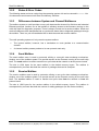
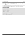
3.2.6
31/216
Channel Mailboxes (Details of Send and Receive Mailboxes)
Master Status
Offset
Type
Name
Description
0x0200
UINT16
usPackagesAccepted
Packages Accepted
Number of Packages that can
be Accepted
0x0202
UINT16
usReserved
Reserved
Set to 0
0x0204
UINT8
abSendMbx[ 1596 ]
Send Mailbox
Non Cyclic Data To The
Network or to the Protocol Stack
0x0840
UINT16
usWaitingPackages
Packages waiting
Counter of packages that are
waiting to be processed
0x0842
UINT16
usReserved
Reserved
Set to 0
0x0844
UINT8
abRecvMbx[ 1596 ]
Receive Mailbox
Non Cyclic Data from the
network or from the
protocol stack
Table 18: Channel Mailboxes.
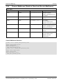
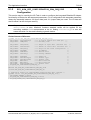
Channel Mailboxes Structure
typedef struct tagNETX_SEND_MAILBOX_BLOCK
{
UINT16 usPackagesAccepted;
UINT16 usReserved;
UINT8 abSendMbx[ 1596 ];
} NETX_SEND_MAILBOX_BLOCK;
typedef struct tagNETX_RECV_MAILBOX_BLOCK
{
UINT16 usWaitingPackages;
UINT16 usReserved;
UINT8 abRecvMbx[ 1596 ];
} NETX_RECV_MAILBOX_BLOCK;
EtherNet/IP Scanner |
DOC050702API10EN | Revision 10 | English | 2010-12 | Released | Public
© Hilscher, 2006-2010
Dual-Port Memory
3.3
32/216
Status
A status block is present within the communication channel. It contains information about network
and task related issues. In some respects, status and control block are used together in order to
exchange information between host application and netX firmware. The application reads a status
block whereas the control block is written by the application. Both status and control block have
registers that use the Change of State mechanism (see also section 2.2.1 of the netX Dual-PortMemory manual).
3.3.1 Common Status
The Common Status Block contains information that is the same for all communication channels.
The start offset of this block depends on the size and location of the preceding blocks. The status
block is always present in the dual-port memory.
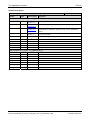
3.3.1.1
All Implementations
The structure outlined below is common to all protocol stacks.
Common Status Structure Definition
Common Status
Offset
Type
Name
Description
0x0010
UINT32
ulCommunicationCOS
Communication Change of
State
READY, RUN, RESET
REQUIRED, NEW, CONFIG
AVAILABLE, CONFIG
LOCKED
0x0014
UINT32
ulCommunicationState
Communication State
NOT CONFIGURED, STOP,
IDLE, OPERATE
0x0018
UINT32
ulCommunicationError
Communication Error
Unique Error Number
According to Protocol Stack
0x001C
UINT16
usVersion
Version
Version Number of this
Diagnosis Structure
0x001E
UINT16
usWatchdogTime
Watchdog Timeout
Configured Watchdog Time
0x0020
UINT16
usHandshakeMode
Handshake Mode
Process Data Transfer Mode
(see netX DPM Interfce
Manual)
0x0022
UINT16
usReserved
Reserved
Set to 0
0x0024
UINT32
ulHostWatchdog
Host Watchdog
Joint Supervision Mechanism
Protocol Stack Writes, Host
System Reads
EtherNet/IP Scanner |
DOC050702API10EN | Revision 10 | English | 2010-12 | Released | Public
© Hilscher, 2006-2010
Dual-Port Memory
0x0028
33/216
UINT32
ulErrorCount
Error Count
Total Number of Detected Error
Since Power-Up or Reset
0x002C
UINT32
ulErrorLoglnd
Error Log Indicator
Total Number Of Entries In The
Error Log
Structure (not supported yet)
0x0030
UINT32
ulReserved[2]
Reserved
Set to 0
Table 19: Common Status Structure Definition
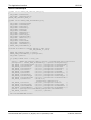
Common Status Block Structure Reference
typedef struct NETX_COMMON_STATUS_BLOCK_Ttag
{
UINT32 ulCommunicationCOS;
UINT32 ulCommunicationState;
UINT32 ulCommunicationError;
UINT16 usVersion;
UINT16 usWatchdogTime;
UINT16 ausReserved[2];
UINT32 ulHostWatchdog;
UINT32 ulErrorCount;
UINT32 ulErrorLogInd;
UINT32 ulReserved[2];
union
{
NETX_MASTER_STATUS_T tMasterStatus;
/* for master implementation */
UINT32
aulReserved[6];
/* otherwise reserved
*/
} unStackDepended;
} NETX_COMMON_STATUS_BLOCK_T;
EtherNet/IP Scanner |
DOC050702API10EN | Revision 10 | English | 2010-12 | Released | Public
© Hilscher, 2006-2010
Dual-Port Memory
34/216
Common Status Block Structure Reference
typedef struct NETX_COMMON_STATUS_BLOCK_Ttag
{
UINT32 ulCommunicationCOS;
UINT32 ulCommunicationState;
UINT32 ulCommunicationError;
UINT16 usVersion;
UINT16 usWatchdogTime;
UINT16 ausReserved[2];
UINT32 ulHostWatchdog;
UINT32 ulErrorCount;
UINT32 ulErrorLogInd;
UINT32 ulReserved[2];
union
{
NETX_MASTER_STATUS_T tMasterStatus;
/* for master implementation */
UINT32
aulReserved[6];
/* otherwise reserved
*/
} unStackDepended;
} NETX_COMMON_STATUS_BLOCK_T;
Communication Change of State (All Implementations)
The communication change of state register contains information about the current operating
status of the communication channel and its firmware. Every time the status changes, the netX
protocol stack toggles the netX Change of State Command flag in the netX communication flags
register (see section 3.2.2.1 of the netX DPM Interface Manual). The application then has to toggle
the netX Change of State Acknowledge flag back acknowledging the new state (see section
3.2.2.2 of the netX DPM Interface Manual, ref.#1).
ulCommunicationCOS - netX writes, Host reads
Bit
Short name
Name
D31..D7
unused, set to zero
D6
Restart Required Enable
RCX_COMM_COS_RESTART_REQUIRED_ENABLE
D5
Restart Required
RCX_COMM_COS_RESTART_REQUIRED
D4
Configuration New
RCX_COMM_COS_CONFIG_NEW
D3
Configuration Locked
RCX_COMM_COS_CONFIG_LOCKED
D2
Bus On
RCX_COMM_COS_BUS_ON
D1
Running
RCX_COMM_COS_RUN
D0
Ready
RCX_COMM_COS_READY
Table 20: Communication State of Change
EtherNet/IP Scanner |
DOC050702API10EN | Revision 10 | English | 2010-12 | Released | Public
© Hilscher, 2006-2010
Dual-Port Memory
35/216
Communication Change of State Flags (netX System Ö Application)
Bit
Definition / Description
0
Ready (RCX_COMM_COS_READY)
0-…
1 - The Ready flag is set as soon as the protocol stack is started properly. Then the protocol stack is
awaiting a configuration. As soon as the protocol stack is configured properly, the Running flag is set,
too.
1
Running (RCX_COMM_COS_RUN)
0-…
1 -The Running flag is set when the protocol stack has been configured properly. Then the protocol
stack is awaiting a network connection. Now both the Ready flag and the Running flag are set.
2
Bus On (RCX_COMM_COS_BUS_ON)
0-…
1 -The Bus On flag is set to indicate to the host system whether or not the protocol stack has the
permission to open network connections. If set, the protocol stack has the permission to
communicate on the network; if cleared, the permission was denied and the protocol stack will not
open network connections.
3
Configuration Locked (RCX_COMM_COS_CONFIG_LOCKED)
0-…
1 -The Configuration Locked flag is set, if the communication channel firmware has locked the
configuration database against being overwritten. Re-initializing the channel is not allowed in this
state. To unlock the database, the application has to clear the Lock Configuration flag in the control
block (see page 42).
4
Configuration New (RCX_COMM_COS_CONFIG_NEW)
0-…
1 -The Configuration New flag is set by the protocol stack to indicate that a new configuration became
available, which has not been activated. This flag may be set together with the Restart Required flag.
5
Restart Required (RCX_COMM_COS_RESTART_REQUIRED)
0-…
1 -The Restart Required flag is set when the channel firmware requests to be restarted. This flag is
used together with the Restart Required Enable flag below. Restarting the channel firmware may
become necessary, if a new configuration was downloaded from the host application or if a
configuration upload via the network took place.
6
Restart Required Enable (RCX_COMM_COS_RESTART_REQUIRED_ENABLE)
0-…
1 - The Restart Required Enable flag is used together with the Restart Required flag above. If set,
this flag enables the execution of the Restart Required command in the netX firmware (for details on
the Enable mechanism see section 2.3.2 of the netX DPM Interface Manual)).
7 … 31
Reserved, set to 0
Table 21: Meaning of Communication Change of State Flags
EtherNet/IP Scanner |
DOC050702API10EN | Revision 10 | English | 2010-12 | Released | Public
© Hilscher, 2006-2010
Dual-Port Memory
36/216
Communication State (All Implementations)
The communication state field contains information regarding the current network status of the
communication channel. Depending on the implementation, all or a subset of the definitions below
is supported.
UNKNOWN
NOT_CONFIGURED #define RCX_COMM_STATE_NOT_CONFIGURED 0x00000001
STOP
IDLE #define RCX_COMM_STATE_IDLE 0x00000003
OPERATE #define RCX_COMM_STATE_OPERATE 0x00000004
#define RCX_COMM_STATE_UNKNOWN 0x00000000
#define RCX_COMM_STATE_STOP 0x00000002
Communication Channel Error (All Implementations)
This field holds the current error code of the communication channel. If the cause of error is
resolved, the communication error field is set to zero (= RCX_SYS_SUCCESS) again. Not all of the
error codes are supported in every implementation. Protocol stacks may use a subset of the error
codes below.
SUCCESS #define RCX_SYS_SUCCESS 0x00000000
Runtime Failures
WATCHDOG TIMEOUT #define RCX_E_WATCHDOG_TIMEOUT 0xC000000C
Initialization Failures
(General) INITIALIZATION FAULT
#define RCX_E_INIT_FAULT
0xC0000100
DATABASE ACCESS FAILED #define RCX_E_DATABASE_ACCESS_FAILED
0xC0000101
Configuration Failures
NOT CONFIGURED
(General) CONFIGURATION FAULT
#define RCX_E_CONFIGURATION_FAULT
#define RCX_E_NOT_CONFIGURED
0xC0000119
0xC0000120
INCONSISTENT DATA SET #define RCX_E_INCONSISTENT_DATA_SET
0xC0000121
DATA SET MISMATCH
INSUFFICIENT LICENSE #define RCX_E_INSUFFICIENT_LICENSE
0xC0000123
PARAMETER ERROR #define RCX_E_PARAMETER_ERROR 0xC0000124
INVALID NETWORK ADDRESS
0xC0000125
NO SECURITY MEMORY#define RCX_E_NO_SECURITY_MEMORY
#define RCX_E_DATA_SET_MISMATCH 0xC0000122
#define RCX_E_INVALID_NETWORK_ADDRESS
EtherNet/IP Scanner |
DOC050702API10EN | Revision 10 | English | 2010-12 | Released | Public
0xC0000126
© Hilscher, 2006-2010
Dual-Port Memory
37/216
Network Failures
(General) NETWORK FAULT
CONNECTION CLOSED #define RCX_COMM_CONNECTION_CLOSED 0xC0000141
CONNECTION TIMED OUT #define RCX_COMM_CONNECTION_TIMEOUT 0xC0000142
LONELY NETWORK #define RCX_COMM_LONELY_NETWORK
DUPLICATE NODE #define RCX_COMM_DUPLICATE_NODE 0xC0000144
CABLE DISCONNECT #define RCX_COMM_CABLE_DISCONNECT 0xC0000145
#define RCX_COMM_NETWORK_FAULT 0xC0000140
0xC0000143
Version (All Implementations)
The version field holds version of this structure. It starts with one; zero is not defined.
STRUCTURE VERSION #define RCX_STATUS_BLOCK_VERSION 0x0001
Watchdog Timeout (All Implementations)
This field holds the configured watchdog timeout value in milliseconds. The application may set its
watchdog trigger interval accordingly. If the application fails to copy the value from the host
watchdog location to the device watchdog location, the protocol stack will interrupt all network
connections immediately regardless of their current state. For details, see section 4.13 of the netX
DPM Interface Manual.
Host Watchdog (All Implementations)
The protocol stack supervises the host system using the watchdog function. If the application fails
to copy the value from the device watchdog location (section 3.2.5 of the netX DPM Interface
Manual) to the host watchdog location (section 3.2.4 of the netX DPM Interface Manual), the
protocol stack assumes that the host system has some sort of problem and shuts down all network
connections. For details on the watchdog function, refer to section 4.13 of the netX DPM Interface
Manual.
Error Count (All Implementations)
This field holds the total number of errors detected since power-up, respectively after reset. The
protocol stack counts all sorts of errors in this field no matter if they were network related or caused
internally.
Error Log Indicator (All Implementations)
Not supported yet: The error log indicator field holds the number of entries in the internal error log.
If all entries are read from the log, the field is set to zero.
EtherNet/IP Scanner |
DOC050702API10EN | Revision 10 | English | 2010-12 | Released | Public
© Hilscher, 2006-2010
Dual-Port Memory
3.3.1.2
38/216
Master Implementation
In addition to the common status block as outlined in the previous section, a master firmware
maintains the following structure.
Master Status Structure Definition
typedef struct NETX_MASTER_STATUS_Ttag
{
UINT32 ulSlaveState;
UINT32 ulSlaveErrLogInd;
UINT32 ulNumOfConfigSlaves;
UINT32 ulNumOfActiveSlaves;
UINT32 ulNumOfDiagSlaves;
UINT32 ulReserved;
} NETX_MASTER_STATUS_T;
Master Status
Offset
Type
Name
Description
0x0010
Structure
See common structure in Table 19: Common Status
Structure Definition
0x0038
UINT32
ulSlaveState
Slave State
OK, FAILED (At Least One
Slave)
0x003C
UINT32
ulSlaveErrLogInd
Slave Error Log Indicator
Slave Diagnosis Data Available:
EMPTY, AVAILABLE
0x0040
UINT32
ulNumOfConfigSlaves
Configured Slaves
Number of Configured Slaves
On The Network
0x0044
UINT32
ulNumOfActiveSlaves
Active Slaves
Number of Slaves Running
Without Problems
0x0048
UINT32
ulNumOfDiagSlaves
Faulted Slaves
Number of Slaves Reporting
Diagnostic Issues
0x004C
UINT32
ulReserved
Reserved
Set to 0
Table 22: Master Status Structure Definition
EtherNet/IP Scanner |
DOC050702API10EN | Revision 10 | English | 2010-12 | Released | Public
© Hilscher, 2006-2010
Dual-Port Memory
39/216
Slave State
The slave state field is available for master implementations only. It indicates whether the master is
in
cyclic data exchange to all configured slaves. In case there is at least one slave missing or if the
slave
has a diagnostic request pending, the status is set to FAILED. For protocols that support non-cyclic
communication only, the slave state is set to OK as soon as a valid configuration is found.
Status and Error Codes
Code (Symbolic Constant)
Numerical Value
Meaning
RCX_SLAVE_STATE_UNDEFINED
0x00000000
UNDEFINED
RCX_SLAVE_STATE_OK
0x00000001
OK
RCX_SLAVE_STATE_FAILED
0x00000002
FAILED (at least one slave)
Others are reserved
Table 23: Status and Error Codes
Slave Error Log Indicator
The error log indicator field holds the number of entries in the internal error log. If all entries are
read from the log, the field is set to zero.
Note: This function is not yet supported.
Number of Configured Slaves
The firmware maintains a list of slaves to which the master has to open a connection. This list is
derived from the configuration database created by SYCON.net (see 6.1). This field holds the
number of configured slaves.
Number of Active Slaves
The firmware maintains a list of slaves to which the master has successfully opened a connection.
Ideally, the number of active slaves is equal to the number of configured slaves. For certain
Fieldbus systems it could be possible that the slave is shown as activated, but still has a problem
in terms of a diagnostic issue. This field holds the number of active slaves.
EtherNet/IP Scanner |
DOC050702API10EN | Revision 10 | English | 2010-12 | Released | Public
© Hilscher, 2006-2010
Dual-Port Memory
40/216
Number of Faulted Slaves
If a slave encounters a problem, it can provide an indication of the new situation to the master in
certain fieldbus systems. As long as those indications are pending and not serviced, the field holds
a value unequal zero. If no more diagnostic information is pending, the field is set to zero.
3.3.1.3
Slave Implementation
The slave firmware uses only the common structure as outlined in section 3.2.5.1 of the Hilscher
netX Dual-Port-Memory Manual.
3.3.2 Extended Status
The content of the channel specific extended status block is specific to the implementation.
Depending on the protocol, a status area may or may not be present in the dual-port memory. It is
always available in the default memory map (see section 3.2.1 of netX Dual-Port Memory Manual).
Note: Each offset is always related to the begin of correspondent channel start.
The definition of the first structure remains specific to correspondent protocol and contains
additional information about network status (i.e. flags, error counters, events etc.).
The Extended Status Block for EtherNet/IP Scanner describes the last error which has occurred. It
is stored at the location of the offset 0x0050 and structured as follows:
Extended Status Block – First part (EIP_CODE_DIAG_T)
Offset
Type
Name
Description
0x0050
UINT32
ulInfoCount
Info count
0x0054
UINT32
ulWarningCount
Warning count
0x0058
UINT32
ulErrorCount
Error count
0x005C
UINT32
ulLevel
Error Level (Info / Warning or
Error)
0x0060
UINT32
ulCode
Error Code
0x0064
UINT32
ulParameter
Parameter of the error code
0x0068
UINT32
ulLine
Line in the source code where
the error happened.l
0x006C
UINT8[12]
abModulName[12]
Source identifier
0x0078
UINT8[]
bReserved[132]
Reserved for further status
information
Table 24: Extended Status Block (for EtherNet/IP Scanner Protocol Stack)
The second structure begins at offset 0x00FC and provides the definition of the up to 32
independent State Fields. These state fields can be defined to represent a kind of bit-list, byte-list
etc. with up to 65535 entities. In this way a common access mechanism for different state
definitions and quantities can be provided independent of protocol implementation.
EtherNet/IP Scanner |
DOC050702API10EN | Revision 10 | English | 2010-12 | Released | Public
© Hilscher, 2006-2010
Dual-Port Memory
41/216
The second part of the Extended Status Block is structured as follows:
Extended Status Block for EtherNet/IP Scanner – Second part (State Field Definition Block)
Offset
Type
Name
Description/Value
0x00FC
unsigned char
bReserved[3]
Reserved. Do not use.
0x00FF
unsigned char
bNumStateStructs
Number of State Structures defined below = 3
È
NETX_EXTENDED_
STATE_STRUCT_T
atStateStruct[0]
Structure to define State field properties
0x0100
unsigned char
bStateArea
=0. State field is located in standard input area of channel
0
unsigned char
bStateTypeID
=1. Corresponds to a bitlist (one bit per node ) of
configured nodes
unsigned short
usNumOfStateEntries
=128. Corresponds to 128 bits, each representing a slave
unsigned long
ulStateOffset
Contains an offset pointer to a state field inside input data
area 0, which contains the slave configuration area
È
NETX_EXTENDED_
STATE_STRUCT_T
atStateStruct[1]
Structure to define State field properties
0x0110
unsigned char
bStateArea
=0. State field is located in standard input area of channel
0
unsigned char
bStateTypeID
=2. Corresponds to a bitlist (one bit per node ) of active
nodes
unsigned short
usNumOfStateEntries
=128. Corresponds to 128 bits, each representing a slave
unsigned long
ulStateOffset
Contains an offset pointer to a state field inside input data
area 0, which contains the slave state information area
È
NETX_EXTENDED_
STATE_STRUCT_T
atStateStruct[2]
Structure to define State field properties
0x0120
unsigned char
bStateArea
=0. State field is located in standard input area of channel
0
unsigned char
bStateTypeID
=3. Corresponds to a bitlist (one bit per node ) of
diagnostic nodes
unsigned short
usNumOfStateEntries
=128. Corresponds to 128 bits, each representing a slave
unsigned long
ulStateOffset
Contains an offset pointer to a state field inside input data
area 0, which contains the slave diagnostic area
Table 25: Extended Status Block for EtherNet/IP Scanner – Second part (State Field Definition Block)
If the location of the state fields is defined to be inside of input data area 0 block (as it is shown in
generic example above), the corresponding bitlists will be updated by the stack consistently to the
data in this area. Moreover, the data and corresponding state fields can be read out by the host
application as one data block i.e. with DMA support.
EtherNet/IP Scanner |
DOC050702API10EN | Revision 10 | English | 2010-12 | Released | Public
© Hilscher, 2006-2010
Dual-Port Memory
3.4
42/216
Control Block
A control block is always present within the communication channel. In some respects, control and
status block are used together in order to exchange information between host application and netX
firmware. The control block is written by the application, whereas the application reads a status
block. Both control and status block have registers that use the Change of State mechanism (see
also section 2.2.1 of the netX Dual-Port-Memory manual.)
The following gives an example of the use of control and status block. The host application wishes
to lock the configuration settings of a communication channel to protect them against changes. The
application sets the Lock Configuration flag in the control block to the communication channel
firmware. As a result, the channel firmware sets the Configuration Locked flag in the status block
(see below), indicating that the current configuration settings cannot be deleted, altered,
overwritten or otherwise changed.
The control block of a dual-port memory features a watchdog function to allow the operating
system running on the netX supervise the host application and vice versa. The control area is
always present in the dual-port memory.
Control Block
Offset
Type
Name
Description
0x0008
UINT32
ulApplicationCOS
Application Change Of State
State Of The Application
Program
INITIALIZATION, LOCK
CONFIGURATION
0x000C
UINT32
ulDeviceWatchdog
Device Watchdog
Host System Writes, Protocol
Stack Reads
Table 26: Communication Control Block
Communication Control Block Structure
typedef struct NETX_CONTROL_BLOCK_Ttag
{
UINT32 ulApplicationCOS;
UINT32 ulDeviceWatchdog;
} NETX_CONTROL_BLOCK_T;
For more information concerning the Control Block please refer to the netX DPM Interface Manual,
ref. #1.
EtherNet/IP Scanner |
DOC050702API10EN | Revision 10 | English | 2010-12 | Released | Public
© Hilscher, 2006-2010
Getting started / Configuration
43/216
4 Getting started / Configuration
This section explains some essential information you should know when starting to work with the
EtherNet/IP Scanner Protocol API.
4.1
Overview about essential Functionality
The most commonly used functionality of the Ethernet/IP Scanner Protocol API is described within
the following sections of this document:
Topic
Section Number Section Name
Set configuration
5.1.2
EIP_APM_SET_CONFIGURATION_PRM_REQ/CNF - Set Configuration
5.2.7
EIP_OBJECT_SET_OUTPUT_REQ/CNF – Setting the Output Data
Cyclic data
transfer
(Input/Output)
3
5.2.8
EIP_OBJECT_GET_INPUT_REQ/CNF – Getting the latest Input Data
3
3
5.2.2
EIP_OBJECT_AS_REGISTER_REQ/CNF – Register a new Assembly Instance
Acyclic data
5.2.17
transfer (Records)
5.2.18
EIP_OBJECT_OPEN_CL3_REQ/CNF – Open Class 3 Connection
EIP_OBJECT_CONNECT_MESSAGE_REQ/CNF – Send a Class 3 Message
Request
5.2.19
EIP_OBJECT_CLOSE_CL3_REQ/CNF – Close Class 3 Connection
5.2.16
EIP_OBJECT_UNCONNECT_MESSAGE_REQ/CNF – Send an unconnected
Message Request
Table 27: Overview about essential Functionality.
Note: I/O-Data should be exchanged via tri-state-buffers.
EtherNet/IP Scanner |
DOC050702API10EN | Revision 10 | English | 2010-12 | Released | Public
© Hilscher, 2006-2010
Getting started / Configuration
4.2
44/216
Configuration Parameters
4.2.1
Using the Device Driver to write into the DPM
The EtherNet/IP Scanner contains a complete EtherNet/IP Adapter.
adapter part is described within this section:
The configuration of this
In order to provide the integrated EtherNet/IP Adapter with the correct warmstart parameters follow
the procedure described in section 3.4.6 “Setting Warmstart Parameters” of the cifX Driver
Installation Manual. Transfer these parameters to your Hilscher device using the method described
in subsection 3.4.6.4 “Transferring new Warmstart Parameters”. Finally, you need to reset your
device in order to perform a warmstart. After the warmstart is finished without error, the new
parameters are active.
The following table gives a description of the configuration parameters (formerly denominated as
warmstart parameters), which you can set using the device driver:
Parameter
Meaning
Range of Value / Value
Communication
List field to select the communication system
Here: Ethernet/IP
The start of the device can be performed either application controlled or
automatically:
Application controlled,
System
Bus Startup
Automatic
Automatic: Network connections are opened automatically without taking
care of the state of the host application.
Application controlled: The channel firmware is forced to wait for the
host application to wait for the Application Ready flag in the
communication change of state register (see section 3.2.5.1 of the netX
DPM Interface Manual).
For more information concerning this topic see section 4.4.1 “Controlled
or Automatic Start” of the netX DPM Interface Manual.
I/O Data Status
Status of the input or the output data.
None, 1 Byte, 4 Byte
For each input and output date the following status information (in byte)
is memorized in the dual-port memory:
Status 0 = None
Status 1 = 1 Byte (currently not supported)
Status 2 = 4 Byte (currently not supported)
Input Length
Length of the input data in byte
0… 504 Byte
Output Length
Length of the output data in byte
0… 504 Byte
Vendor ID
Identification number of the manufacturer
0 … (216 - 1),
Hilscher: 283
Product Type
Communication adapter
0 … (216 - 1),
Hilscher: 12
Product Code
Product code of the device
0 … (216 - 1),
Hilscher: 0x102 (hex)
Major Rev
Major revision
0 … 255,
Hilscher: 1
Minor Rev
Minor revision
0 … 255,
Hilscher: 1
IP Address
IP address of the station
Valid IP address
Net mask
Network mask of the station
Valid net mask
EtherNet/IP Scanner |
DOC050702API10EN | Revision 10 | English | 2010-12 | Released | Public
© Hilscher, 2006-2010
Getting started / Configuration
45/216
Parameter
Meaning
Range of Value / Value
Gateway
Gateway address of the station
Valid IP address of
gateway
Flags
BootP:
Default: DHCP
DHCP:
100Mbit: Speed Selection,
FullDuplex: Duplex Operation
Auto-neg.: Auto-Negotiation,
Table 28: Meaning and allowed Values for Configuration Parameters.
The following flags are available:
BootP: If set, the device obtains its configuration from a BOOTP server.
DHCP: If set, the device obtains its configuration from a DHCP server.
100Mbit: Speed Selection, If set, the device will operate at 100 Mbit/s, else at 10 Mbit/s. This
parameter will not be in effect, when auto-negotiation is active.
FullDuplex: Duplex Operation,
If set, full-duplex operation will be enabled. The device will operate in half-duplex mode, if
this parameter is set to zero. This parameter will not be in effect, when auto-negotiation is
active.
Auto-neg.: Auto-Negotiation,
If set, the device will auto-negotiate link parameters with the remote hub or switch.
4.2.2
Write Access to the Dual-Port Memory
In order to write the warmstart parameters into the corresponding area of the dual-port memory
and to perform a warmstart subsequently, the EIP_APM_WARMSTART_PRM_REQ packet has
to be sent to the protocol stack. For more information how to accomplish this, please refer to
section 5.1.1 of this manual.
4.2.3
Using the configuration Tool SYCON.net
The easiest way to configure the EtherNet/IP Scanner is using Hilscher’s configuration tool
SYCON.net. This tool is described in a separate documentation.
EtherNet/IP Scanner |
DOC050702API10EN | Revision 10 | English | 2010-12 | Released | Public
© Hilscher, 2006-2010
Getting started / Configuration
4.3
46/216
Task Structure of the EtherNet/IP Scanner Stack
The figure below displays the internal structure of the tasks which together represent the
EtherNet/IP Scanner Stack:
System Area
DPM
MBX
Out
MBX
In
MBX
Task
MBX
Task
Handshake Area
HC
HC
Channel Area
MBX
Out
Channel
MBX
In
Out
In
netX
DB
config.nxd
nwid.nxd
EIM_AP-Task
rX-System
A
Watchdog
Timer
B
C
A
B
Triple Buffer
for cyclic IO
EIM_OBJECT
Task
EIP_ENCAP
Task
C
EIM_CL1
Task
Send
Timer
Function Interface
Packet Interface
EIM_TCPIP Task
Other kind of
relation
xC
Standard Ethernet or 2-Port Switch
Figure 6: Internal Structure of EtherNet/IP Scanner Firmware
For the explanation of the different kinds of arrows see lower left corner of figure.
The dual-port memory is used for exchange of information, data and packets. Configuration and IO
data will be transferred using this way.
The user application only accesses the task located in the highest layer namely the EIM_AP-task
which constitute the application interface of the EtherNet/IP Scanner Stack.
The EIM_OBJECT task, EIP_ENCAP task and EIM_CL1 task represent the core of the EtherNet/IP
Scanner Stack.
The TCP/IP task represent the TCP/IP Stack, which is used by the EtherNet/IP Scanner.
EtherNet/IP Scanner |
DOC050702API10EN | Revision 10 | English | 2010-12 | Released | Public
© Hilscher, 2006-2010
Getting started / Configuration
47/216
In detail, the various tasks have the following functionality and responsibilities:
EIM_AP task
The EIM_AP task provides the interface to the user application and the control of the stack. It also
completely handles the DualPort Memory interface of the communication channel. In detail, it is
responsible for the following:
Handling the communication channels DPM-interface
Process data exchange
channel mailboxes
Watchdog
Provides Status and diagnostic
Handling applications packets (all packets described in Protocol Interface Manual)
Configuration packets
Packet Routing
Handling stacks indication packets
Provide information about state of every connection contained in configuration
Evaluation of data base files
Preparation of configuration data
EIP_OBJECT task
The EIP_OBJECT task is the main part of the EtherNet/IP Stack. The task is responsible for the
following items:
CIP object directory
Connection establishment
Explicit messaging
Connection managment
EIM_ENCAP task
The EIM_ENCAP task implements the encapsulation layer of the EtherNet/IP. It handles the
interface to the TCP/IP Stack and manage all TCP connections.
EIM_CL1 task
The EIM_CL1 task has the highest priority. The Task is responsible for the implicit messaging. The
Task has a interface to the EDD and manages the handling of the cyclic communication.
EIS_DLR task
The EIS_DLR task provides support for the DLR technology for creating a single ring topology with
media redundancy. For more information see next section.
TCP/IP task
The TCP/IP task coordinates the EtherNet/IP stack with the underlying TCP/IP stack. It provides
services required by the EIM_ENCAP task.
EtherNet/IP Scanner |
DOC050702API10EN | Revision 10 | English | 2010-12 | Released | Public
© Hilscher, 2006-2010
Getting started / Configuration
4.4
48/216
DLR
This section intends to give a brief and compact overview about the basic facts and concepts of the
DLR networking technology now supported by Hilscher’s EtherNet/IP Adapter protocol stack.
4.4.1
Fundamentals of DLR
DLR is an abbreviation for Device Level Ring. It is defined in ref. #4, section “9-5 Device Level
Ring”, page 9-11 and following.
DLR is a technology (based on a special protocol additionally to Ethernet/IP) for creating a single
ring topology with media redundancy.
It is based on Layer 2 (Data link) of the ISO/OSI model of networking and thus transparent for
higher layers (except the existence of the DLR object providing configuration and diagnosis
capabilities which is described in section 1.4.3“Object Modeling” of this document).
In general, there are two kinds of nodes in the network:
Ring supervisors
Ring nodes
DLR requires all modules (both supervisors and usual ring nodes) to be equipped with two
Ethernet ports and internal switching technology.
Each module within the DLR network checks the target address of the currently received frame
whether it matches its own MAC address.
If yes, it keeps the packet and processes it. It will not be propagated any further.
If no, it propagates the packet via the other port which did not receive the packet.
There is a ring topology so that all devices in the DLR network are each connected to two different
neighbors with their two Ethernet ports. In order to avoid looping, one port of the (active) supervisor
is blocked (besides for some special frames).
1.
Ring Supervisors
There are two kinds of supervisors defined:
Active supervisors
Back-up supervisors
Note: Hilscher devices running an EtherNet/IP firmware (it does not matter, whether this is
a Scanner or an Adapter firmware) are not able to act as a ring supervisor!
Active supervisors
An active ring supervisor has the following duties:
It periodically sends beacon and announce frames.
It permanently verifies the ring integrity.
It reconfigures the ring in order to ensure operation in case of single faults.
It collects diagnostic information from the ring.
At least one active ring supervisor is required within a DLR network.
EtherNet/IP Scanner |
DOC050702API10EN | Revision 10 | English | 2010-12 | Released | Public
© Hilscher, 2006-2010
Getting started / Configuration
49/216
Back-up supervisors
It is recommended but not necessary that each DLR network should have at least one back-up
supervisor. If the active supervisor of the network fails, the back-up supervisor will take over the
duties of the active supervisor.
2.
Precedence Rule for Multi-Supervisor Operation
Multi-Supervisor Operation is allowed for DLR networks. If more than one supervisor is configured
as active on the ring, the following rule applies in order to determine the supervisor which is
relevant:
Each supervisor contains an internal precedence number which can be configured. The supervisor
within the ring carrying the highest precedence number will be the active supervisor, the others will
behave passively and switch back to the state of back-up supervisors.
3.
Beacon and Announce Frames
Beacon frames and announce frames are both used to inform the devices within the ring about the
transition (i.e. the topology change) from linear operation to ring operation of the network.
They differ in the following:
Direction
Beacon frames are sent in both directions.
Announce frames are sent only in one direction of the ring, however.
Frequency
Beacon frames are always sent every beacon interval. Usually, a beacon interval is defined to have a
duration of 400 microseconds. However, beacon frames may be sent even faster up to a duration
of 100 microseconds.
Announce frames are always sent in time intervals of one second.
Support for Precedence Number
Only Beacon frames contain the internal precedence number of the supervisor which sent them
Support for Network Fault Detection
Loss of beacon frames allows the active supervisor to detect and discriminate various types of network
faults of the ring on its own.
4.
Ring Nodes
This subsection deals with modules in the ring which do not have supervisor capabilities. These are
denominated as (usual) ring nodes.
There are two modes of operation for usual ring nodes within the network:
Beacon-based operation
Announce-based operation
EtherNet/IP Scanner |
DOC050702API10EN | Revision 10 | English | 2010-12 | Released | Public
© Hilscher, 2006-2010
Getting started / Configuration
50/216
A DLR network may contain an arbitrary number of usual nodes.
Nodes for beacon-based operation have the following capabilities
They implement the DLR protocol, but without the ring supervisor capability
They must be able to process beacon frames
Nodes for announce-based operation have the following capabilities
They implement the DLR protocol, but without the ring supervisor capability
They do not process beacon frames
but they are able to forward beacon frames
They must be able to process announce frames
Note: Hilscher devices running an EtherNet/IP firmware (it does not matter, whether this is
a Scanner or an Adapter firmware) always run as a beacon-based ring node.
A ring node (independently whether it works beacon-based or announce-based) may have three internal
states.
IDLE_STATE
FAULT_STATE
NORMAL_STATE
For a beacon-based ring node, these states are defined as follows:
IDLE_STATE
The IDLE_STATE is the state which is reached after power-on. In IDLE_STATE the network
operates as linear network, there is no ring support active. If on one port a beacon frame
from a supervisor is received, the state changes to FAULT_STATE.
FAULT_STATE
The Ring node reaches the FAULT_STATE after the following conditions:
1. If a beacon frame from a supervisor is received on at least one port
2. If a beacon frame from a different supervisor than the currently active one is
received on at least one port and the precedence of this supervisor is higher than
that of the currently active one.
The FAULT_STATE provides partial ring support, but the ring is still not fully operative in
FAULT_STATE. If the beacon frames have a time-out on both ports, the state will change to
the IDLE_STATE. If on both ports a beacon frame is received and a beacon frame with
RING_NORMAL_STATE has been received, the state changes to NORMAL_STATE.
NORMAL_STATE
The Ring node reaches the NORMAL_STATE only after the following condition:
•
If a beacon frame from the active supervisor is received on both ports and a beacon
frame with RING_NORMAL_STATE has been received
The NORMAL_STATE provides full ring support. The following conditions will cause a
change to the FAULT_STATE:
1. A link failure has been detected.
EtherNet/IP Scanner |
DOC050702API10EN | Revision 10 | English | 2010-12 | Released | Public
© Hilscher, 2006-2010
Getting started / Configuration
51/216
2. A beacon frame with RING_FAULT_STATE has been received from the active
supervisor on at least one port.
3. A beacon frame from the active supervisor had a time-out on at least one port
4. A beacon frame from a different supervisor than the currently active one is received
on at least one port and the precedence of this supervisor is higher than that of the
currently active one.
For an announce-based ring node, these states are defined as follows:
IDLE_STATE
The IDLE_STATE is the state which is reached after power-on. It can also be reached from
any other state if the announce frame from the active supervisor has a time-out. In
IDLE_STATE the network operates as linear network, there is no ring support active. If an
announce frame with FAULT_STATE is received from a supervisor, the state changes to
FAULT_STATE.
FAULT_STATE
The Ring node reaches the FAULT_STATE after the following conditions:
1. If the network is in IDLE_STATE and an announce frame with FAULT_STATE is
received from any supervisor.
2. If the network is in NORMAL_STATE and an announce frame with FAULT_STATE is
received from the active or a different supervisor.
3. If the network is in NORMAL_STATE and a link failure has been detected.
The FAULT_STATE provides partial ring support, but the ring is still not fully operative in
FAULT_STATE.
If the announce frame from the active supervisor has a time-out, the state will fall back to the
IDLE_STATE.
If an announce frame with NORMAL_STATE has been received from the active or a different
supervisor, the state changes to NORMAL_STATE.
NORMAL_STATE
The Ring node reaches the NORMAL_STATE only after the following condition:
•
If the network is in IDLE_STATE and an announce frame with NORMAL_STATE is
received from any supervisor.
•
If the network is in FAULT_STATE and an announce frame with NORMAL_STATE
is received from the active or a different supervisor.
The NORMAL_STATE provides full ring support. The following conditions will cause a fall
back to the FAULT_STATE:
5. A link failure has been detected.
6. A announce frame with FAULT_STATE has been received from the active or a
different supervisor.
The following conditions will cause a fall back to the IDLE _STATE:
7. The announce frame from the active supervisor has a time-out.
5.
Normal Network Operation
EtherNet/IP Scanner |
DOC050702API10EN | Revision 10 | English | 2010-12 | Released | Public
© Hilscher, 2006-2010
Getting started / Configuration
52/216
In normal operation, the supervisor sends beacon and, if configured, announce frames in order to monitor
the state of the network. Usual ring nodes and back-up supervisors receive these frames and react. The
supervisor may send announce frames once per second and additionally, if an error is detected.
6.
Rapid Fault/Restore Cycles
Sometimes a series of rapid fault and restore cycles may occur in the DLR network for instance if a
connector is faulty. If the supervisor detects 5 faults within a time period of 30 seconds, it sets a flag (Rapid
Fault/Restore Cycles) which must explicitly be reset by the user then. This can be accomplished via the
“Clear Rapid Faults” service.
7.
States of Supervisor
A ring supervisor may have five internal states.
IDLE_STATE
FAULT_STATE (active)
NORMAL_STATE (active)
FAULT_STATE (backup)
NORMAL_STATE (backup)
For a ring supervisor, these states are defined as follows:
FAULT_STATE (active)
The FAULT_STATE (active) is the state which is reached after power-on if the supervisor
has been configured as supervisor.
The supervisor reaches the FAULT_STATE (active) after the following conditions:
1. As mentioned above, at power-on
2. From NORMAL_STATE (active):
If a link failure occurs or if a link status frame indicating a link failure is received from a
ring node or if the beacon time-out timer expires on one port
3. From FAULT_STATE (backup):
If on both ports there is a time-out of the beacon frame from the currently active
supervisor
The FAULT_STATE (active) provides partial ring support, but the ring is still not fully
operative in FAULT_STATE (active).
If a beacon frame from a different supervisor than the currently active one is received on at
least one port and the precedence of this supervisor is higher, the state will fall back to the
FAULT_STATE (backup).
If on both ports an own beacon frame has been received, the state changes to
NORMAL_STATE (active).
NORMAL_STATE (active)
The supervisor reaches the NORMAL_STATE (active) only after the following condition:
•
If an own beacon frame is received on both ports during FAULT_STATE (active).
The NORMAL_STATE provides full ring support.
EtherNet/IP Scanner |
DOC050702API10EN | Revision 10 | English | 2010-12 | Released | Public
© Hilscher, 2006-2010
Getting started / Configuration
53/216
The following conditions will cause a change to the FAULT_STATE (active):
2. A link failure has been detected.
3. A link status frame indicating a link failure is received from a ring node
4. The beacon time-out timer expires on one port
The following conditions will cause a change to the FAULT_STATE (backup):
1. A beacon frame from the active supervisor had a time-out on at least one port
2. If a beacon frame from a different supervisor with higher precedence is received on at
least one port.
FAULT_STATE (backup)
The supervisor reaches the FAULT_STATE (backup) after the following conditions:
1. From NORMAL_STATE (active):
A beacon frame from a supervisor with higher precedence is received on at least one
port.
2. From FAULT_STATE (active):
A beacon frame from a different supervisor with higher precedence and the
precedence of this supervisor is higher.
3. From NORMAL_STATE (backup):
A link failure has been detected.
A beacon frame with RING_FAULT_STATE is received from the active supervisor
The beacon time-out timer (from the active supervisor) expires on one port
A beacon frame from a different supervisor with higher precedence and the
precedence of this supervisor is higher.
4. From IDLE_STATE:
A beacon frame is received from any supervisor on one port
The FAULT_STATE (backup) provides partial ring support, but the ring is still not fully
operative in FAULT_STATE (backup).
The following condition will cause a transition to the FAULT_STATE (active):
The beacon time-out timer (from the active supervisor) expires on both ports
The following condition will cause a transition to the NORMAL_STATE (backup):
Beacon frames from the active supervisor are received on both ports and a beacon
frame with RING_NORMAL_STATE has been received.
The following condition will cause a transition to the IDLE_STATE:
The beacon time-out timer (from the active supervisor) expires on both ports
EtherNet/IP Scanner |
DOC050702API10EN | Revision 10 | English | 2010-12 | Released | Public
© Hilscher, 2006-2010
Getting started / Configuration
54/216
NORMAL_STATE (backup)
The supervisor reaches the NORMAL_STATE (backup) only after the following condition:
•
Beacon frames from the active supervisor are received on both ports and a beacon
frame with RING_NORMAL_STATE has been received.
The NORMAL_STATE (backup) provides full ring support. The following conditions will
cause a change to the FAULT_STATE (backup):
1. A link failure has been detected.
2. A beacon frame with RING_FAULT_STATE has been received from the active
supervisor on at least one port.
3. The beacon time-out timer (from the active supervisor) expires on both ports.
4. A beacon frame from a different supervisor with higher precedence and the
precedence of this supervisor is higher.
IDLE_STATE
The IDLE_STATE is the state which is reached after power-on if the supervisor has not been
configured as supervisor.
In IDLE_STATE the network operates as linear network, there is no ring support active. If on
one port a beacon frame from a supervisor is received, the state changes to FAULT_STATE
(backup).
For more details refer to the DLR specification in reference #4, section “9-5 Device Level Ring”.
EtherNet/IP Scanner |
DOC050702API10EN | Revision 10 | English | 2010-12 | Released | Public
© Hilscher, 2006-2010
Getting started / Configuration
55/216
Attributes of DLR Object
The following table gives a more detailed description of the attributes of the DLR Object.
Attribute ID 1
Attribute Name
1
Network Topology
2
Network Status
3
Ring Supervisor Status
4
Ring Supervisor Config Structure, see below
5
Ring Faults Count
6
Last Active Node on Port 1
7
Last Active Node on Port 2
8
Ring Protocol Participants Count
9
Ring Protocol Participants List
10
Active Supervisor Address
11
Active Supervisor Precedence
12
Capability Flags
Table 29: Attributes of DLR Object and their Attribute ID
1.
Network Topology (Attribute ID 1)
This unsigned integer value contains a code for the current network topology. The coding is as follows:
0
Linear topology
1
Ring topology
This attribute reflects the current state of the DLR network’s topology.
The following rules apply:
In IDLE_STATE, the attribute’s value should be 0 indicating linear topology.
In NORMAL_STATE or FAULT_STATE, the attribute’s value should be 1 indicating ring topology.
Under the following conditions a DLR network node will start with ring topology (1):
If the device is supervisor-capable and it is initialized as supervisor.
Under the following conditions a DLR network node will start with linear topology (0):
If the device is supervisor-capable and it is not initialized as supervisor.
If the device is supervisor-capable and it cannot support the currently valid ring parameters.
If the device is not supervisor-capable.
EtherNet/IP Scanner |
DOC050702API10EN | Revision 10 | English | 2010-12 | Released | Public
© Hilscher, 2006-2010
Getting started / Configuration
2.
56/216
Network Status (Attribute ID 2)
This attribute reflects the current state of the DLR network representing the device’s view onto the network.
It indicates either normal operation or the currently valid kind of error situation according to the table below:
Value
Meaning
0
Normal operation
1
Ring fault
2
Unexpected loop detected
3
Partial network fault
4
Rapid fault/restore cycle
Table 30: Possible Values of the Network Status
The value 0 indicates normal operation without any error both in linear and in ring mode.
Value 1 is only applicable while there is currently a ring topology. It indicates the detection of a ring
fault.
Value 2 is only applicable while there is currently a linear topology. It indicates the detection of a loop
within the network
Value 3 is only applicable while there is currently a ring topology. It indicates the detection of a network
fault only in one direction.
Value 4 is applicable both in linear and in ring topology mode. It indicates the detection of a series of
rapid fault/restore cycles in the DLR network. Rapid fault/restore cycles are explained in subsection
1.a.i.6 “Rapid Fault/Restore Cycles” on page 52 of this document.
3.
Ring Supervisor Status (Attribute ID 3)
This attribute contains the information about the node’s status as supervisor in the DLR network according to
the table below:
Value
Meaning
0
Node operates as a backup supervisor.
1
Node operates as an active ring supervisor.
2
Node operates as a normal ring node.
3
Node operates in non-DLR topology (no supervisor present)
4
Node cannot support at least one of the currently valid ring operation parameters (Beacon interval or
beacon timeout)
Table 31: Possible Values of the Ring Supervisor Status
EtherNet/IP Scanner |
DOC050702API10EN | Revision 10 | English | 2010-12 | Released | Public
© Hilscher, 2006-2010
Getting started / Configuration
4.
57/216
Ring Supervisor Config Structure (Attribute ID 4)
This attribute contains a structure providing information about the following configuration parameters relevant
for the operation of the ring:
Supervisor precedence value
Beacon interval
Beacon timeout
VLAN ID
Supervisor enabled/disabled status
Supervisor precedence value
This structure member contains the precedence value for the node which has been assigned to it by the user
if it is capable of working as a supervisor. This value allows to determine the node to select as supervisor in
case of multiple nodes enabled as supervisor within the network.
It is an integer value within the range between 0 and 255. The default value is 0. Higher values indicate
higher precedence. Thus the node with the highest precedence will be active supervisor in case of multiple
supervisor-enabled nodes. In case of equal precedence the node with the higher MAC address will be
selected as active supervisor.
Beacon interval
This structure member contains the time interval to be used for generation of beacon frames by the
supervisor. A range from 400 microseconds to 100 milliseconds should be supported where 400
microseconds represents the default value .
The supervisor may support lower beacon intervals but this is no requirement as 400 milliseconds should
usually be sufficient. The absolute minimum allowed value of the beacon interval is 100 microseconds.
Beacon timeout
This structure member contains the time (specified in microseconds) to wait for reception of beacon frame
until a beacon time-out occurs.
The default value for beacon time-out is 1960 microseconds. This value has to be adapted to the network
size and conditions.
The beacon time-out may not be lower than twice the beacon interval. If the beacon interval changes and
this condition is not met any longer, the supervisor will automatically adjust the beacon time-out accordingly.
VLAN ID
This structure member contains the VLAN ID to be used in DLR protocol frames. Allowed values range from
0 to 4094 where 0 indicates no VLAN is used.
EtherNet/IP Scanner |
DOC050702API10EN | Revision 10 | English | 2010-12 | Released | Public
© Hilscher, 2006-2010
Getting started / Configuration
58/216
Supervisor enabled/disabled
This structure member contains the status whether the supervisor functionality in a supervisor-capable node
is enabled or disabled. Setting this value to TRUE enables the supervisor functionality while setting it to
FALSE disables the supervisor functionality. The default value is FALSE.
5.
Ring Faults Count (Attribute ID 5)
This attribute contains the number of ring fault detection events since power up of the node. Ring faults can
only be detected while being either in active supervisor mode or in backup supervisor mode. If the node is
not enabled as supervisor, this count will remain 0.
If necessary, this value can be reset to 0 using the Set_Attribute_Single service.
6.
Last Active Node on Port 1 (Attribute ID 6)
This attribute contains
the IP address and/or Ethernet MAC address of the last node which could be reached via port 1, if the
node is an active supervisor (i.e. the current ring supervisor status is equal to 1).
the value 0, if one of the following conditions is met:
The node is not enabled as ring supervisor.
The node is not enabled as a backup supervisor.
This attribute is initialized with the value 0.
7.
Last Active Node on Port 2 (Attribute ID 7)
This attribute contains
the IP address and/or Ethernet MAC address of the last node which could be reached via port 2, if the
node is an active supervisor (i.e. the current ring supervisor status is equal to 1).
the value 0, if one of the following conditions is met:
The node is not enabled as ring supervisor.
The node is not enabled as a backup supervisor.
This attribute is initialized with the value 0.
8.
Ring Protocol Participants Count (Attribute ID 8)
This attribute contains
the number of members in the Ring Protocol Participants List explained just below, if the node is an
active supervisor (i.e. the current ring supervisor status is equal to 1).
otherwise the value 0.
This attribute is initialized with the value 0.
EtherNet/IP Scanner |
DOC050702API10EN | Revision 10 | English | 2010-12 | Released | Public
© Hilscher, 2006-2010
Getting started / Configuration
9.
59/216
Ring Protocol Participants List (Attribute ID 9)
This attribute contains a list of all nodes participating in the ring protocol, if the node is an active supervisor.
It can be accessed via the GetMember service.
If the node is not an active supervisor, the DLR object will return status code 0x0C indicating an object
conflict on access to the this attribute.
If the capacity of the list is exceeded, the last entry will be filled up with 0xFF entries and no more new
entries will be made.
10.
Active Supervisor Address (Attribute ID 10)
This attribute contains the IP address and/or Ethernet MAC address of the currently active supervisor.
It is initialized with the value 0 until the currently active supervisor has been determined.
11.
Active Supervisor Precedence (Attribute ID 11)
This attribute contains the precedence value of the currently active supervisor.
It is initialized with the value 0 until the currently active supervisor has been determined.
12.
Capability Flags (Attribute ID 12)
The nodes DLR capabilities can be determined using the capability flags. The following table explains the
meaning of the single bits:
Bit
No.
Name of bit
Meaning
0
Announce-based ring node
Indicates the node works on the basis of announce
frames, if set.
1
Beacon-based ring node
Indicates the node works on the basis of beacon
frames, if set.
2-4
Reserved
Reserved, set to 0.
5
Supervisor capable
Indicates the node is able to provide supervisor
functionality, if set.
6-31
Reserved
Reserved, set to 0.
Table 32: Capability Flags
Bits 0 and 1 are mutually exclusive. One of these must be set.
For more details refer to the DLR specification in reference #4, section “5-5 Device Level Ring”.
EtherNet/IP Scanner |
DOC050702API10EN | Revision 10 | English | 2010-12 | Released | Public
© Hilscher, 2006-2010
Getting started / Configuration
ii.
60/216
Services of DLR Object
The DLR object supports the services listed in Table 33: Services of the DLR Object and their ServiceID
below:
ServiceID
Service Name
0x01
Get_Attributes_All
0x0E
Get_Attributes_Single
0x10
Set_Attributes_Single
0x18
Get_Member
0x4B
Verify_Fault_Location
0x4C
Clear_Rapid_Faults
0x4D
Restart_Sign_on
Table 33: Services of the DLR Object and their ServiceID
Get_Attributes_All (Service Code 0x01)
This service returns all attributes in numerical order. It is required for instances, optional for the class.
On class level, the class attributes are returned in numerical order.
On instance level, the response depends on whether the node is supervisor-capable or not. In the first
case, the response is the following:
Attribute ID
1
Size
Contents
1
1
Network Topology
2
1
Network Status
3
1
Ring Supervisor Status
4
12
Ring Supervisor Config Structure, see below
5
2
Ring Faults Count
6
10
Last Active Node on Port 1
7
10
Last Active Node on Port 2
8
2
Ring Protocol Participants Count
10
10
Active Supervisor Address
11
1
Active Supervisor Precedence
12
4
Capability Flags
Table 34: Response of Get_Attributes_All for supervisor-capable devices
Otherwise , the response is the following:
Attribute ID
1
Size
Contents
1
1
Network Topology
2
1
Network Status
10
10
Active Supervisor Address
12
4
Capability Flags
Table 35: Response of Get_Attributes_All for not supervisor-capable devices
EtherNet/IP Scanner |
DOC050702API10EN | Revision 10 | English | 2010-12 | Released | Public
© Hilscher, 2006-2010
Getting started / Configuration
61/216
Get_Attributes_Single
This service returns the value of single attributes. It is required for instances, optional for the class.
Set_Attributes_Single
This service modifies single attributes. It is required for all supervisors.
Get_Member
This service is especially used for access to the Ring Protocol Participants List described in section 9 “Ring
Protocol Participants List (Attribute ID 9)” on page 59 of this document.
Verify_Fault_Location
This service causes the ring supervisor to verify fault locations. Using this service will cause an update of
Last Active Node on Port 1 and Last Active Node on Port 2.
Clear_Rapid_Faults
This service clears the Rapid Fault/Restore Cycles condition and allows to return to normal operation of the
ring supervisor. It is required for supervisors.
Restart_Sign_on
This service restarts the sign-on process, if it is currently not in progress.
The sign-on process is described in section 9-5.5.2.3 of the CIP specification (reference #4).
EtherNet/IP Scanner |
DOC050702API10EN | Revision 10 | English | 2010-12 | Released | Public
© Hilscher, 2006-2010
62/216
4.5
Obtaining Diagnostic Information from connected Slaves
by sending an RCX_GET_SLAVE_CONN_INFO_REQ Packet
An application which is based on Hilscher’s DPM for netX can obtain diagnostic and status
information about all slaves connected to and administered by this master from the master
firmware as described in general in the netX DPM Manual (Ref. 1). (This information only concerns
cyclic data transfer.) The EtherNet/IP Scanner firmware supports this feature.
The netX operating system rcX uses handles in order to access at the slaves. This is done in a
possibly unexpected way as these handles are:
not equal to IP address
not equal to the connection number
Retrieving the diagnostic information is a two-step-process as you first retrieve the handle using
the Get Slave Handle request and subsequently you retrieve the diagnostic information using the
handle.
1. Retrieve the handle by the Get Slave Handle request (RCX_GET_SLAVE_HANDLE_REQ,
Command code 0x2F08) which is described in the netX DPM Manual (Ref. 1), chapter
5.2.2.1. In order to do so, you need to choose which kind of list of the above mentioned slave
lists
you
want
to
obtain.
The
confirmation
packet
you
will
receive
(RCX_GET_SLAVE_HANDLE_CNF, Command code 0x2F09) will then deliver an array of
handles to the elements of the selected list.
2. This allows to obtain a diagnosis structure for the specific slave by the Get Slave Connection
Information request (RCX_GET_SLAVE_CONN_INFO_REQ, Command code 0x2F0A). This
packet requires the handle of the specific slave taken from the array of handles to the
elements of the selected list obtained in the first step. You will then receive the confirmation
packet (RCX_GET_SLAVE_CONN_INFO_CNF, Command code 0x2F0B) delivering – besides
others – a structure tState containing the following structure with information about the
selected slave from the master firmware (see reference 1 for more details). For an
EtherNet/IP Adapter this structure looks as follows:
typedef struct EIP_DIAG_GET_SLAVE_DIAGtag {
UINT32 ulState;
UINT8 bGenStatus;
UINT8 bReserved;
UINT16 usExtStatus;
UINT16 usVendorId;
UINT16 usProductType;
UINT16 usProductCode;
UINT8 bMajRevision;
UINT8 bMinRevision;
STRING abIP[32];
STRING abConnectionName[64];
} EIP_DIAG_GET_SLAVE_DIAG;
The variables of this structure have the following meaning:
Main State
ulState
This variable contains the slave state of the selected slave.
EtherNet/IP Scanner |
DOC050702API10EN | Revision 10 | English | 2010-12 | Released | Public
© Hilscher, 2006-2010
63/216
Connection Status Variables:
bGenStatus –
This byte contains the General Status Code of the connection. The possible General
Status Codes are listed in section 6 of this document or in the “The CIP Networks
Library, Volume 1: Common Industrial Protocol Specification“, Appendix B-1 General
Status Codes
bReserved1
This is a padding byte for correct byte alignment.
usExtStatus
This variable contains the Extended Status depending on the current value of the General Status
Code.
Target Device Identity Object Variables:
These five variables are used to exactly identify the device.
Note: None of these five variables should have the value 0!
The parameter ulVendID is a Vendor specific Vendor ID. With the parameter ulProductType
and ulProductCode the AP-Task defines which kind of device it implements. Please see the CIP
specification for more details. The parameters ulMajRev and ulMinRev contain the revision
(major revision number and minor revision number) of the device to be identified.
usVendorID
The vendor identification is an identification number uniquely identifying the manufacturer
of an EtherNet/IP device. In this context, the value 283 is denoting the device has been
manufactured by Hilscher. Vendor IDs are managed by the Open DeviceNet Vendor
Association, Inc. (ODVA) and ControlNet International (CI).
usProductType
This variable characterizes the general type of the device, for instance 0x0C denotes that
the device is a communication adapter. The list of device types is managed by ODVA and
ControlNet International. It is used for identification of the device profile of a particular
product . Device profiles define the minimum requirements and common options a device
needs to implement.
A list of the currently defined device types is published in chapter 6-1 of “The CIP
Networks Library, Volume 1: Common Industrial Protocol Specification”.
usProductCode
This variable delivers an identification of a particular product of an individual vendor of
EtherNet/IP devices. Each vendor may assign this code to each of its products. In this
context, the value 258 is used by Hilscher devices.
The Product Code typically maps to one or more model numbers of a manufacturer.
Products should have different codes if their configuration options and/or runtime
behaviour are different as such devices present a different logical view to the network.
EtherNet/IP Scanner |
DOC050702API10EN | Revision 10 | English | 2010-12 | Released | Public
© Hilscher, 2006-2010
64/216
bMinRev
This variable identifies the less important part of the revision of the item the Identity Object
is representing. Minor revisions should be displayed as three digits with leading zeros as
necessary.
bMajRev
This variable identifies the more important part of the revision of the item the Identity
Object is representing. Major revision values are limited to 7 bits. The eighth bit is
reserved by the CIP standard and must be zero (as a default value).
The major revision should be incremented by the vendor every time when there is a
significant change to the functionality of the product. Changes affecting the configuration
choices for the user always require a new major revision number.
The minor revision is typically used to identify changes in a product that do not change
choices in the user configuration such as bug fixes, hardware component change etc.
IP Address Variables
abIP[32]
This variable specifies an array containing the IP address information
Connection Name Variables
Each connection can be named by an individual connection name.
abConnName[EIP_CONNECTION_NAME_LEN]
This variable specifies the connection name itself. The name is just for identification purposes, it is
irrelevant to all aspects of communication configuration.
EtherNet/IP Scanner |
DOC050702API10EN | Revision 10 | English | 2010-12 | Released | Public
© Hilscher, 2006-2010
The Application Interface
5
65/216
The Application Interface
This chapter defines the application interface of the EtherNet/IP Scanner stack.
The application itself has to be developed as a task according to the Hilscher’s Task Layer
Reference Model. The application task is named AP-Task in the following sections and chapters.
The AP-Task’s process queue shall keep track of its incoming packets. It provides the
communication channel for the underlying EtherNet/IP Scanner stack. Once, the EtherNet/IP
Scanner stack communication is established, events received by the stack are mapped to packets
that are sent to the AP-Task’s process queue. Every packet has to be evaluated in the AP-Task’s
context and corresponding actions be executed. Additionally, Initiator-Services that are to be
requested by the application are sent via predefined queue macros to the underlying EtherNet/IP
Scanner stack queues via packets as well.
The following chapters describe the packets that may be received or sent by the AP-Task.
5.1
The APM-Task
The APM-Task is the interface between stack and dual-port-memory. The application should be
able to send all commands (packets) to this task. At the APM-Task handle also the services of the
other tasks and uses data of interest. The task has routing functionality.
To get the handle of the process queue of the EipAPM-Task the macro TLR_QUE_IDENTIFY()
must be used in conjunction with the ASCII-Queue name “EIPAPM_QUE”.
ASCII Queue name
Description
"EIPAPM_QUE”
Name of the APM-Task process queue
Table 36: EipAPM-Task Process Queue
The returned handle has to be used as value ulDest in all initiator packets the AP-Task intends to
send to the APM-Task. This handle is the same handle that has to be used in conjunction with the
macros TLR_QUE_SENDPACKET_FIFO/LIFO() for sending a packet to the APM-Task.
In detail, the following functionality is provided by the APM-Task:
Topic
No. of section Packets
Page
Set configuration 5.1.2
EIP_APM_SET_CONFIGURATION_PRM_REQ/CNF - Set Configuration
71
Registering
5.1.2
EIP_APM_REGISTER_APP_REQ/CNF - Register Application
71
5.1.4
EIP_APM_UNREGISTER_APP_REQ/CNF - Unregister Application
78
Application
Unregistering
Application
Table 37: Topics of APM-Task and associated packets
EtherNet/IP Scanner |
DOC050702API10EN | Revision 10 | English | 2010-12 | Released | Public
© Hilscher, 2006-2010
The Application Interface
5.1.1
66/216
EIP_APM_WARMSTART_PRM_REQ/CNF - Set Warmstart Parameter
This service may be used by the AP-Task in order to configure the integrated EtherNet/IP Adapter
functionality of the device with warmstart parameters. For a configuration with warmstart parameter
always the assembly instance 100 (input data) and 101 (output data) are used. The I/O data will
start at offset 0 at the dual port memory.
Note: This packet is obsolete and will not longer supported after September,1, 2009. It is replaced
by packet EIP_APM_SET_CONFIGURATION_PRM_REQ/CNF - Set Configuration described
in the next subsection which contains identical functionality. Do not use this packet for all
new developments!
Note: If you set usVendId, usProductCode, bMinorRev, bMajorRev and the length of
abDeviceName to zero, Hilscher’s firmware standard values will be applied for the
according variables. It is recommended to do so. Setting usProductType to zero will
cause the value 0 to be used indicating a generic device.
Packet Structure Reference
typedef struct EIP_APM_WARMSTART_PRM_REQ_Ttag {
TLR_UINT32 ulSystemFlags;
/*!< IO status length (not used yet)
TLR_UINT32 ulWdgTime;
/*!< Watchdog time
*/
*/
TLR_UINT32
TLR_UINT32
ulInputLen;
ulOutputLen;
/*!< Length of input data (Instance 100) */
/*!< Length of output data (Instance 101) */
TLR_UINT32
TLR_UINT32
TLR_UINT32
TLR_UINT32
ulTcpFlag;
ulIpAddr;
ulNetMask;
ulGateway;
/*!<
/*!<
/*!<
/*!<
Flags for TCP stack configuration
IP-address
Network mask
Gateway address
*/
*/
*/
*/
/*!<
/*!<
/*!<
/*!<
/*!<
/*!<
Vendor ID
Product type
Product code
Minor Revision
Major Revision
Product name
*/
*/
*/
*/
*/
*/
TLR_UINT16 usVendId;
TLR_UINT16 usProductType;
TLR_UINT16 usProductCode;
TLR_UINT8
bMinorRev;
TLR_UINT8
bMajorRev;
TLR_UINT8
abDeviceName[32];
} EIP_APM_WARMSTART_PRM_REQ_T;
#define EIP_APM_WARMSTART_PRM_REQ_SIZE (sizeof(EIP_APM_WARMSTART_PRM_REQ_T))
/* Indication Packet for acknowledged connectionless data transfer */
typedef struct EIP_APM_PACKET_WARMSTART_PRM_REQ_Ttag {
TLR_PACKET_HEADER_T tHead;
EIP_APM_WARMSTART_PRM_REQ_T tData;
} EIP_APM_PACKET_WARMSTART_PRM_REQ_T;
EtherNet/IP Scanner |
DOC050702API10EN | Revision 10 | English | 2010-12 | Released | Public
© Hilscher, 2006-2010
The Application Interface
67/216
Packet Description
structure EIP_APM_PACKET_WARMSTART_PRM_REQ_T
Variable
Type
Type: Request
Value / Range Description
tHead - Structure TLR_PACKET_HEADER
ulDest
UINT32
0x20/
EIPAPM_QUE
Destination Queue-Handle
ulSrc
UINT32
0 ... 232-1
Source Queue-Handle
ulDestId
UINT32
See rules in
section 3.2.1
Destination End Point Identifier, specifying the final receiver of the
packet within the Destination Process. Set to 0 for the Initialization
Packet
ulSrcId
UINT32
See rules in
section 3.2.1
Source End Point Identifier, specifying the origin of the packet inside
the Source Process
ulLen
UINT32
Packet Data Length in bytes
32
0 ... 2 -1
Packet Identification as unique number generated by the Source
Process of the Packet
ulId
UINT32
ulSta
UINT32
ulCmd
UINT32
0x3600
EIP_APM_WARMSTART_PRM_REQ - Command
ulExt
UINT32
0
Extension not in use, set to zero for compatibility reasons
ulRout
UINT32
x
Routing, do not touch
See chapter Status/Error Codes Overview. .
tData - Structure EIP_APM_WARMSTART_PRM_REQ_T
ulSystemFlags UINT32
Default value:
0
indicating
AUTOSTART
Allowed
values: 0,1
System Flags
BIT 0: AUTOSTART(0) / APPLICATION CONTROLLED(1)
BIT 1 I/O Status Enable (not yet implemented)
BIT 2 I/O Status 8/32Bit (not yet implemented)
BIT 3 - 31 not yet implemented
0 - communication with a controller after a device start is allowed
without BUS_ON flag, but the communication will be interrupted if the
BUS_ON flag changes state to 0 ;
1 - communication with controller is allowed only with the BUS_ON
flag.
ulWdgTime
UINT32
Default value:
1000
Allowed
values:
Watchdog time (in milliseconds).
A value of 0 simply indicates that the watchdog timer has been
switched off.
0..65535
ulInputLen
UINT32
Default value:
Length of input data (Instance 100)
16
Allowed
values:
0..504
ulOutputLen
UINT32
Default value:
Length of Output data (Instance 101)
16
Allowed
values:
0..504
ulTcpFlag
UINT32
Default value:
Flags for TCP stack configuration, see detailed explanation below:
0x00000410
EtherNet/IP Scanner |
DOC050702API10EN | Revision 10 | English | 2010-12 | Released | Public
© Hilscher, 2006-2010
The Application Interface
68/216
structure EIP_APM_PACKET_WARMSTART_PRM_REQ_T
ulIPAddr
UINT32
Default value:
Type: Request
IP address
0.0.0.0
Allowed
values:
All valid IPaddresses
ulNetMask
UINT35
Default value:
Network mask
0.0.0.0
Allowed
values:
All valid IPaddresses
ulGateway
UINT32
Default value:
Gateway address
0.0.0.0
Allowed
values:
All valid IPaddresses
usVendorID
UINT16
Default value:
283 (denoting
the device has
been
manufactured
by Hilscher)
Allowed
values:
Vendor identification:
This is an identification number for the manufacturer of an ETHERNET
IP device.
[0x0000..0xFFFF]; vendor ID MSB != 0; vendor ID LSB != 0; vendor ID
MSB != 0xFF
0..65535
usProductType UINT16
Default value: Product type
12 (denoting
the device is a
communication
interface)
Allowed
values:
0..65535
usProductCode UINT16
Default value:
258
Product code
Allowed
values:
0..65535
bMinorRev
UINT8
Default value:
1
Minor revision
Allowed
values:
0..255
bMajorRev
UINT8
Default value:
1
Major revision
Allowed
values:
0..255
abDeviceName
UINT8[3
2]
Product name (The first byte indicates the length, byte 2 -31 contain
the characters of the product name)
Note: The length you apply in the first byte must be the current length
of the following product name.
Table 38: EIP_APM_PACKET_WARMSTART_PRM_REQ– Set Warmstart Parameter
EtherNet/IP Scanner |
DOC050702API10EN | Revision 10 | English | 2010-12 | Released | Public
© Hilscher, 2006-2010
The Application Interface
69/216
The following flags are available within variable ulTcpFlag:
BIT 0: IP address available
BIT 1: Net mask available
BIT 2: Gateway available
BIT 3: Enable BOOTP:
If set, the device obtains its configuration from a BOOTP server.
BIT 4: Enable DHCP: :
If set, the device obtains its configuration from a DHCP server. (This is the default)
BIT 5 - BIT 9: Reserved
BIT 10: Auto-Negotiation:
If set, the device will auto-negotiate link parameters with the remote hub or switch.
BIT 11: Full Duplex Operation:
If set, full-duplex operation will be enabled. The device will operate in half-duplex mode,
if this parameter is set to zero. This parameter will not be in effect, when auto-negotiation
is active.
BIT 12: Speed Selection (100Mbit):
If set, the device will operate at 100 Mbit/s, else at 10 Mbit/s. This parameter will not be in
effect, when auto-negotiation is active.
BIT 13: Reserved
EtherNet/IP Scanner |
DOC050702API10EN | Revision 10 | English | 2010-12 | Released | Public
© Hilscher, 2006-2010
The Application Interface
70/216
Packet Structure Reference
#define EIP_APM_WARMSTART_PRM_CNF_SIZE 0
/* Indication Packet for acknowledged connectionless data transfer */
typedef struct EIP_APM_PACKET_WARMSTART_PRM_CNF_Ttag {
TLR_PACKET_HEADER_T tHead;
} EIP_APM_PACKET_WARMSTART_PRM_CNF_T;
Packet Description
Structure EIP_APM_PACKET_WARMSTART_PRM_CNF_T
Variable
Type
Value / Range
Type: Confirmation
Description
tHead - Structure TLR_PACKET_HEADER
ulDest
UINT32
Destination queue handle, unchanged
ulSrc
UINT32
Source queue handle, unchanged
ulDestId
UINT32
Destination End Point Identifier, specifying the final receiver of the
packet within the Destination Process. Set to 0 for the Initialization
Packet
ulSrcId
UINT32
Source End Point Identifier, specifying the origin of the packet inside the
Source Process
ulLen
UINT32
Packet Data Length in bytes
32
ulId
UINT32
0 ... 2 -1
ulSta
UINT32
ulCmd
UINT32
0x3601
EIP_APM_WARMSTART_PRM_CNF - Command
ulExt
UINT32
0
Extension, reserved
ulRout
UINT32
x
Routing information, do not change
Packet Identification, unchanged
See chapter Status/Error Codes Overview..
Table 39: EIP_APM_PACKET_WARMSTART_PRM_CNF– Set Warmstart Parameter
EtherNet/IP Scanner |
DOC050702API10EN | Revision 10 | English | 2010-12 | Released | Public
© Hilscher, 2006-2010
The Application Interface
5.1.2
71/216
-
EIP_APM_SET_CONFIGURATION_PRM_REQ/CNF
Configuration
Set
This service may be used by the AP-Task in order to configure the integrated EtherNet/IP Adapter
functionality of the device with warmstart parameters. For a configuration with warmstart parameter
always the assembly instance 100 (input data) and 101 (output data) are used. The I/O data will
start at offset 0 at the dual port memory.
Note: If you set usVendId, usProductCode, bMinorRev, bMajorRev and the length of
abDeviceName to zero, Hilscher’s firmware standard values will be applied for the
according variables. It is recommended to do so. Setting usProductType to zero will
cause the value 0 to be used indicating a generic device.
Packet Structure Reference
typedef struct EIP_APM_SET_CONFIGURATION_PRM_REQ_Ttag {
TLR_UINT32 ulSystemFlags;
/*!< IO status length (not used yet)
TLR_UINT32 ulWdgTime;
/*!< Watchdog time
*/
*/
TLR_UINT32
TLR_UINT32
ulInputLen;
ulOutputLen;
/*!< Length of input data (Instance 100) */
/*!< Length of output data (Instance 101) */
TLR_UINT32
TLR_UINT32
TLR_UINT32
TLR_UINT32
ulTcpFlag;
ulIpAddr;
ulNetMask;
ulGateway;
/*!<
/*!<
/*!<
/*!<
Flags for TCP stack configuration
IP-address
Network mask
Gateway address
TLR_UINT16 usVendId;
/*!< Vendor ID
TLR_UINT16 usProductType;
/*!< Product type
TLR_UINT16 usProductCode;
/*!< Product code
TLR_UINT8
bMinorRev;
/*!< Minor Revision
TLR_UINT8
bMajorRev;
/*!< Major Revision
TLR_UINT8
abDeviceName[32]; /*!< Product name
} EIP_APM_SET_CONFIGURATION_PRM_REQ_T;
*/
*/
*/
*/
*/
*/
*/
*/
*/
*/
#define EIP_APM_SET_CONFIGURATION_PRM_REQ_SIZE
(sizeof(EIP_APM_SET_CONFIGURATION_PRM_REQ_T))
/* Indication Packet for acknowledged connectionless data transfer */
typedef struct EIP_APM_PACKET_SET_CONFIGURATION_PRM_REQ_Ttag {
TLR_PACKET_HEADER_T tHead;
EIP_APM_SET_CONFIGURATION_PRM_REQ_T tData;
} EIP_APM_PACKET_SET_CONFIGURATION_PRM_REQ_T;
EtherNet/IP Scanner |
DOC050702API10EN | Revision 10 | English | 2010-12 | Released | Public
© Hilscher, 2006-2010
The Application Interface
72/216
Packet Description
structure EIP_APM_PACKET_SET_CONFIGURATION_PRM_REQ_T
Variable
Type
Value / Range
Type: Request
Description
tHead - Structure TLR_PACKET_HEADER
ulDest
UINT32
0x20/
EIPAPM_QUE
Destination Queue-Handle
ulSrc
UINT32
0 ... 232-1
Source Queue-Handle
ulDestId
UINT32
See rules in
section 3.2.1
Destination End Point Identifier, specifying the final receiver of the
packet within the Destination Process. Set to 0 for the Initialization
Packet
ulSrcId
UINT32
See rules in
section 3.2.1
Source End Point Identifier, specifying the origin of the packet inside the
Source Process
ulLen
UINT32
Packet Data Length in bytes
32
0 ... 2 -1
Packet Identification as unique number generated by the Source
Process of the Packet
ulId
UINT32
ulSta
UINT32
ulCmd
UINT32
0x3600
EIP_APM_SET_CONFIGURATION_PRM_REQ - Command
ulExt
UINT32
0
Extension not in use, set to zero for compatibility reasons
ulRout
UINT32
x
Routing, do not touch
See chapter Status/Error Codes Overview..
tData - Structure EIP_APM_SET_CONFIGURATION_PRM_REQ_T
ulSystemFlag UINT32
s
Default value: 0
System Flags
indicating
AUTOSTART
BIT 0: AUTOSTART(0) / APPLICATION CONTROLLED(1)
BIT 1 I/O Status Enable (not yet implemented)
BIT 2 I/O Status 8/32Bit (not yet implemented)
BIT 3 - 31 not yet implemented
Allowed values:
0,1
0 - communication with a controller after a device start is allowed
without BUS_ON flag, but the communication will be interrupted if the
BUS_ON flag changes state to 0 ;
1 - communication with controller is allowed only with the BUS_ON flag.
ulWdgTime
UINT32
Default value:
1000
Allowed values:
Watchdog time (in milliseconds).
A value of 0 simply indicates that the watchdog timer has been switched
off.
0..65535
ulInputLen
UINT32
Default value:
Length of input data (Instance 100)
16
Allowed values:
0..504
ulOutputLen
UINT32
Default value:
Length of Output data (Instance 101)
16
Allowed values:
0..504
ulTcpFlag
UINT32
Default value:
Flags for TCP stack configuration, see detailed explanation below:
0x00000410
ulIPAddr
UINT32
Default value:
IP address
0.0.0.0
Allowed values:
All valid IPaddresses
EtherNet/IP Scanner |
DOC050702API10EN | Revision 10 | English | 2010-12 | Released | Public
© Hilscher, 2006-2010
The Application Interface
73/216
structure EIP_APM_PACKET_SET_CONFIGURATION_PRM_REQ_T
ulNetMask
UINT35
Default value:
Type: Request
Network mask
0.0.0.0
Allowed values:
All valid IPaddresses
ulGateway
UINT32
Default value:
Gateway address
0.0.0.0
Allowed values:
All valid IPaddresses
usVendorID
UINT16
Default value:
283 (denoting
the device has
been
manufactured
by Hilscher)
Allowed values:
Vendor identification:
This is an identification number for the manufacturer of an ETHERNET
IP device.
[0x0000..0xFFFF]; vendor ID MSB != 0; vendor ID LSB != 0; vendor ID
MSB != 0xFF
0..65535
usProductTyp UINT16
e
Default value:
12 (denoting
the device is a
communication
interface)
Allowed values:
Product type
0..65535
usProductCod UINT16
e
Default value:
258
Product code
Allowed values:
0..65535
bMinorRev
UINT8
Default value: 1
Minor revision
Allowed values:
0..255
bMajorRev
UINT8
Default value: 1
Major revision
Allowed values:
0..255
abDeviceName UINT8[3
2]
Product name (The first byte indicates the length, byte 2 -31 contain
the characters of the product name)
Note: The length you apply in the first byte must be the current length
of the following product name.
Table 40: EIP_APM_PACKET_SET_CONFIGURATION_PRM_REQ– Set Warmstart Parameter
The following flags are available within variable ulTcpFlag:
BIT 0: IP address available
BIT 1: Net mask available
BIT 2: Gateway available
BIT 3: Enable BOOTP:
If set, the device obtains its configuration from a BOOTP server.
BIT 4: Enable DHCP: :
If set, the device obtains its configuration from a DHCP server. (This is the default)
EtherNet/IP Scanner |
DOC050702API10EN | Revision 10 | English | 2010-12 | Released | Public
© Hilscher, 2006-2010
The Application Interface
BIT 5 - BIT 9: Reserved
BIT 10: Auto-Negotiation:
74/216
If set, the device will auto-negotiate link parameters with the remote hub or switch.
BIT 11: Full Duplex Operation:
If set, full-duplex operation will be enabled. The device will operate in half-duplex mode,
if this parameter is set to zero. This parameter will not be in effect, when auto-negotiation
is active.
BIT 12: Speed Selection (100Mbit):
If set, the device will operate at 100 Mbit/s, else at 10 Mbit/s. This parameter will not be in
effect, when auto-negotiation is active.
BIT 13: Reserved
EtherNet/IP Scanner |
DOC050702API10EN | Revision 10 | English | 2010-12 | Released | Public
© Hilscher, 2006-2010
The Application Interface
75/216
Packet Structure Reference
#define EIP_APM_SET_CONFIGURATION_PRM_CNF_SIZE 0
/* Indication Packet for acknowledged connectionless data transfer */
typedef struct EIP_APM_PACKET_SET_CONFIGURATION_PRM_CNF_Ttag {
TLR_PACKET_HEADER_T tHead;
} EIP_APM_PACKET_SET_CONFIGURATION_PRM_CNF_T;
Packet Description
Structure EIP_APM_PACKET_SET_CONFIGURATION_PRM_CNF_T
Variable
Type
Value / Range
Type: Confirmation
Description
tHead - Structure TLR_PACKET_HEADER
ulDest
UINT32
Destination queue handle, unchanged
ulSrc
UINT32
Source queue handle, unchanged
ulDestId
UINT32
Destination End Point Identifier, specifying the final receiver of the
packet within the Destination Process. Set to 0 for the Initialization
Packet
ulSrcId
UINT32
Source End Point Identifier, specifying the origin of the packet inside
the Source Process
ulLen
UINT32
Packet Data Length in bytes
32
ulId
UINT32
0 ... 2 -1
ulSta
UINT32
ulCmd
UINT32
0x3601
EIP_APM_SET_CONFIGURATION_PRM_CNF - Command
ulExt
UINT32
0
Extension, reserved
ulRout
UINT32
x
Routing information, do not change
Packet Identification, unchanged
See chapter Status/Error Codes Overview..
Table 41: EIP_APM_PACKET_SET_CONFIGURATION_PRM_CNF– Set Warmstart Parameter
EtherNet/IP Scanner |
DOC050702API10EN | Revision 10 | English | 2010-12 | Released | Public
© Hilscher, 2006-2010
The Application Interface
5.1.3
76/216
EIP_APM_REGISTER_APP_REQ/CNF - Register Application
This service is used to register the application at the protocol stack. It is required for correct
operation as without calling this service no indications would be sent back to the sending task or
queue.
Note: This packet will no longer be supported by the firmware described in this document after
September 1, 2009. Use the registering functionality described in the netX Dual-PortMemory Manual instead (RCX_REGISTER_APP_REQ, code 0x2F10).
Packet Structure Reference
typedef struct EIP_APM_PACKET_REGISTER_APP_REQ_Ttag {
TLR_PACKET_HEADER_T tHead;
} EIP_APM_PACKET_REGISTER_APP_REQ_T;
#define EIP_APM_REGISTER_APP_REQ_SIZE 0
Packet Description
Structure EIP_APM_PACKET_REGISTER_APP_REQ_T
Variable
Type
Value / Range
Type: Request
Description
tHead - Structure TLR_PACKET_HEADER
ulDest
UINT32
0x20/
EIPAPM_QUE
Destination Queue-Handle
ulSrc
UINT32
0 ... 232-1
Source Queue-Handle
ulDestId
UINT32
See rules in
section 3.2.1
Destination End Point Identifier, specifying the final receiver of the
packet within the Destination Process. Set to 0 for the Initialization
Packet
ulSrcId
UINT32
See rules in
section 3.2.1
Source End Point Identifier, specifying the origin of the packet inside the
Source Process
ulLen
UINT32
0
Packet Data Length in bytes
32
0 ... 2 -1
Packet Identification as unique number generated by the Source
Process of the Packet
ulId
UINT32
ulSta
UINT32
ulCmd
UINT32
0x3604
EIP_APM_REGISTER_APP_REQ - Command
ulExt
UINT32
0
Extension not in use, set to zero for compatibility reasons
ulRout
UINT32
x
Routing, do not touch
See Table 45: EIP_APM_PACKET_REGISTER_APP_CNF – Packet
Status/Error
Table 42: EIP_APM_PACKET_REGISTER_APP_REQ – Register application
Packet Status/Error
Definition / (Value)
Description
TLR_S_OK
(0x00000000)
Status ok
Table 43: EIP_APM_PACKET_REGISTER_APP_REQ – Register application
EtherNet/IP Scanner |
DOC050702API10EN | Revision 10 | English | 2010-12 | Released | Public
© Hilscher, 2006-2010
The Application Interface
77/216
Packet Structure Reference
typedef struct EIP_APM_PACKET_REGISTER_APP_CNF_Ttag {
TLR_PACKET_HEADER_T tHead;
} EIP_APM_PACKET_REGISTER_APP_CNF_T;
#define EIP_APM_REGISTER_APP_CNF_SIZE 0
Packet Description
Structure EIP_APM_PACKET_REGISTER_APP_CNF_T
Variable
Type
Value / Range
Type: Request
Description
tHead - Structure TLR_PACKET_HEADER
ulDest
UINT32
See rules in
section 3.2.1
Destination queue handle, unchanged
ulSrc
UINT32
See rules in
section 3.2.1
Source queue handle, unchanged
ulDestId
UINT32
See rules in
section 3.2.1
Destination End Point Identifier, specifying the final receiver of the
packet within the Destination Process. Set to 0 for the Initialization
Packet
ulSrcId
UINT32
See rules in
section 3.2.1
Source End Point Identifier, specifying the origin of the packet inside the
Source Process
ulLen
UINT32
0
Packet Data Length in bytes
ulId
UINT32
ulSta
UINT32
ulCmd
UINT32
ulExt
ulRout
32
0 ... 2 -1
Packet Identification, unchanged
See Table 45: EIP_APM_PACKET_REGISTER_APP_CNF – Packet
Status/Error
0x3605
EIP_APM_REGISTER_APP_CNF - Command
UINT32
0
Extension, reserved
UINT32
x
Routing information, do not change
Table 44: EIP_APM_PACKET_REGISTER_APP_CNF – Register application
Packet Status/Error
Definition / (Value)
Description
TLR_S_OK
(0x00000000)
Status ok
TLR_E_EIP_APM_ALREADY_
REGISTERED
An application is already registered.
Table 45: EIP_APM_PACKET_REGISTER_APP_CNF – Packet Status/Error
EtherNet/IP Scanner |
DOC050702API10EN | Revision 10 | English | 2010-12 | Released | Public
© Hilscher, 2006-2010
The Application Interface
5.1.4
78/216
EIP_APM_UNREGISTER_APP_REQ/CNF - Unregister Application
This service is used for unregistering a task or queue at the protocol stack. After unregistering, the
task will not receive indications from the stack any more. If ulFlag is set to 1, unregistering is
forced.
Note: This packet will no longer be supported by the firmware described in this document after
September 1, 2009. Use the unregistering functionality described in the netX Dual-PortMemory Manual instead (RCX_UNREGISTER_APP_REQ).
Packet Structure Reference
typedef struct EIP_APM_UNREGISTER_APP_REQ_Ttag {
TLR_UINT32
ulFlag;
} EIP_APM_UNREGISTER_APP_REQ_T;
typedef struct EIP_APM_PACKET_UNREGISTER_APP_REQ_Ttag {
TLR_PACKET_HEADER_T
tHead;
EIP_APM_UNREGISTER_APP_REQ_T tData;
} EIP_APM_PACKET_UNREGISTER_APP_REQ_T;
#define EIP_APM_UNREGISTER_APP_REQ_SIZE sizeof(EIP_APM_UNREGISTER_APP_REQ_T)
EtherNet/IP Scanner |
DOC050702API10EN | Revision 10 | English | 2010-12 | Released | Public
© Hilscher, 2006-2010
The Application Interface
79/216
Packet Description
Structure EIP_APM_PACKET_UNREGISTER_APP_REQ_T
Variable
Type
Value / Range
Type: Request
Description
tHead - Structure TLR_PACKET_HEADER_T
ulDest
UINT32
0x20/
EIPAPM_QUE
Destination Queue-Handle
ulSrc
UINT32
0 ... 232-1
Source Queue-Handle
ulDestId
UINT32
See rules in
section 3.2.1
Destination End Point Identifier, specifying the final receiver of the
packet within the Destination Process. Set to 0 for the Initialization
Packet
ulSrcId
UINT32
See rules in
section 3.2.1
Source End Point Identifier, specifying the origin of the packet inside the
Source Process
ulLen
UINT32
4
Packet Data Length in bytes
ulId
UINT32
ulSta
UINT32
ulCmd
UINT32
32
0 ... 2 -1
Packet Identification as unique number generated by the Source
Process of the Packet
See Table 49: EIP_APM_PACKET_UNREGISTER_APP_CNF – Packet
Status/Error
0x3606
EIP_APM_UNREGISTER_APP_REQ - Command
ulExt
UINT32
0
Extension not in use, set to zero for compatibility reasons
ulRout
UINT32
x
Routing, do not touch
tData - Structure EIP_APM_UNREGISTER_APP_REQ_T
ulFlag
UINT32
Unregister options
Table 46: EIP_APM_PACKET_UNREGISTER_APP_REQ – Unregister application
Packet Status/Error
Definition / (Value)
Description
TLR_S_OK
(0x00000000)
Status ok
Table 47: EIP_APM_PACKET_UNREGISTER_APP_REQ – Packet Status/Error
EtherNet/IP Scanner |
DOC050702API10EN | Revision 10 | English | 2010-12 | Released | Public
© Hilscher, 2006-2010
The Application Interface
80/216
Packet Structure Reference
typedef struct EIP_APM_PACKET_UNREGISTER_APP_CNF_Ttag {
TLR_PACKET_HEADER_T tHead;
} EIP_APM_PACKET_UNREGISTER_APP_CNF_T;
#define EIP_APM_UNREGISTER_APP_CNF_SIZE 0
Packet Description
Structure EIP_APM_PACKET_UNREGISTER_APP_CNF_T
Variable
Type
Value / Range
Type: Confirmation
Description
tHead - Structure TLR_PACKET_HEADER
ulDest
UINT32
See rules in
section 3.2.1
Destination queue handle, unchanged
ulSrc
UINT32
See rules in
section 3.2.1
Source queue handle, unchanged
ulDestId
UINT32
See rules in
section 3.2.1
Destination End Point Identifier, specifying the final receiver of the
packet within the Destination Process. Set to 0 for the Initialization
Packet
ulSrcId
UINT32
See rules in
section 3.2.1
Source End Point Identifier, specifying the origin of the packet inside
the Source Process
ulLen
UINT32
0
Packet Data Length in bytes
ulId
UINT32
ulSta
UINT32
ulCmd
UINT32
ulExt
ulRout
32
0 ... 2 -1
Packet Identification, unchanged
See Table 49: EIP_APM_PACKET_UNREGISTER_APP_CNF –
Packet Status/Error
0x3607
EIP_APM_UNREGISTER_APP_CNF - Command
UINT32
0
Extension, reserved
UINT32
x
Routing information, do not change
Table 48: EIP_APM_PACKET_UNREGISTER_APP_CNF – Unregister application
Packet Status/Error
Definition / (Value)
Description
TLR_S_OK
(0x00000000)
Status ok
Table 49: EIP_APM_PACKET_UNREGISTER_APP_CNF – Packet Status/Error
EtherNet/IP Scanner |
DOC050702API10EN | Revision 10 | English | 2010-12 | Released | Public
© Hilscher, 2006-2010
The Application Interface
5.2
81/216
The EipObject-Task
The EipObject-Task coordinates, within the EIP-Scanner stack, the overlaying EIP Objects.
It is responsible for all application interactions and represents the counterpart of the AP-Task within
the existing EIP-Scanner stack implementation.
To get the handle of the process queue of the EipObject-Task the Macro
TLR_QUE_IDENTIFY() has to be used in conjunction with the following ASCII-queue name
ASCII Queue name
Description
"OBJECT_QUE”
Name of the EipObject-Task process queue
Table 50: EipObject-Task Process Queue
The returned handle has to be used as value ulDest in all initiator packets the AP-Task intends to
send to the EipObject-Task. This handle is the same handle that has to be used in conjunction
with the macros TLR_QUE_SENDPACKET_FIFO/LIFO() for sending a packet to the EipObjectTask.
In detail, the following functionality is provided by the EipObject-Task:
Topic
No. of
Packets
Page
Message Router Object 5.2.1
EIP_OBJECT_MR_REGISTER_REQ/CNF – Register a new Object at the
Message Router
83
Assembly
5.2.2
Object/Implicit message
transfer
EIP_OBJECT_AS_REGISTER_REQ/CNF – Register a new Assembly
Instance
88
Set Output data
5.2.7
EIP_OBJECT_SET_OUTPUT_REQ/CNF – Setting the Output Data
119
Gewt Input sata
5.2.8
EIP_OBJECT_GET_INPUT_REQ/CNF – Getting the latest Input Data
124
Identity Object
5.2.3
EIP_OBJECT_ID_SETDEVICEINFO_REQ/CNF – Set the Device
Information
94
Connection Manager
Object
5.2.4
EIP_OBJECT_CM_OPEN_CONN_REQ/CNF – Open a new Connection
99
Connection Fault
Indication
5.2.5
EIP_OBJECT_CM_CONN_FAULT_IND/RES – Indicate a Connection Fault
112
Connection Close
5.2.6
EIP_OBJECT_CM_CLOSE_CONN_REQ/CNF – Close a Connection
114
Reset, Ready state
5.2.9
EIP_OBJECT_RESET_IND/RES – Indicate a Reset Request from the
Device
130
Reset
5.2.10
EIP_OBJECT_RESET_REQ/CNF – Request a Reset
131
Change Application
Ready State
5.2.14
EIP_OBJECT_READY_REQ/CNF – Change Application Ready State
143
Indications of various
events
5.2.11
EIP_OBJECT_TCP_STARTUP_CHANGE_IND/RES – Indicate Change of
TCP Parameter
134
Change of connection
Sstate
5.2.12
EIP_OBJECT_CONNECTION_IND/RES – Indicate Change of Connection
State
138
Fatal fault indication
5.2.13
EIP_OBJECT_FAULT_IND/RES – Indicate a fatal Fault
141
Connection
Configuration Object
5.2.15
EIP_OBJECT_REGISTER_CONNECTION_REQ/CNF – Register Connection
at the Connection Configuration Object
145
section
EtherNet/IP Scanner |
DOC050702API10EN | Revision 10 | English | 2010-12 | Released | Public
© Hilscher, 2006-2010
The Application Interface
Topic
No. of
82/216
Packets
Page
section
Unconnected
messaging
5.2.16
EIP_OBJECT_UNCONNECT_MESSAGE_REQ/CNF – Send an unconnected
Message Request
157
Connected messaging
5.2.17
EIP_OBJECT_OPEN_CL3_REQ/CNF – Open Class 3 Connection
161
Send Class 3 Message
Request
5.2.18
EIP_OBJECT_CONNECT_MESSAGE_REQ/CNF – Send a Class 3 Message
Request
164
Close Class 3
Connection
5.2.19
EIP_OBJECT_CLOSE_CL3_REQ/CNF – Close Class 3 Connection
168
Indication of Class 3
Service
5.2.20
EIP_OBJECT_CL3_SERVICE_IND/RES – Indication of Class 3 Service
170
Table 51: Topics of EipObject-Task and associated Packets
EtherNet/IP Scanner |
DOC050702API10EN | Revision 10 | English | 2010-12 | Released | Public
© Hilscher, 2006-2010
The Application Interface
5.2.1
83/216
EIP_OBJECT_MR_REGISTER_REQ/CNF – Register a new Object
at the Message Router
This service has to be used by the AP-Task in order to register a user specific class object at the
message router. The message router receives explicit messages and offers the following
functionality:
Interpretation of class instances specified within messages.
Routing of requests to the specified object
Interpretation of services directly addressed to the message router
Routing of responses to the correct originator of the request
The hObjectQue parameter defines the queue to which all indications are sent. This queue can
be the queue of the AP-Task or any other task. The queue is directly bound to the new object.
The ulClass parameter is the class code of the registered class. The predefined class codes are
described in at the CIP specification Vol. 1 chapter 5.
Parameter ulAccessTyp is reserved for future use.
The macro TLR_QUE_SEND_PACKET_FIFO() has to be used to send the packet to the
EipObject-Task process queue, for more information see source code example below.
Packet Structure Reference
typedef struct EIP_OBJECT_MR_REGISTER_REQ_Ttag {
TLR_HANDLE hObjectQue;
TLR_UINT32 ulClass;
TLR_UINT32 ulAccessTyp;
} EIP_OBJECT_MR_REGISTER_REQ_T;
#define EIP_OBJECT_MR_REGISTER_REQ_SIZE \
sizeof(EIP_OBJECT_MR_REGISTER_REQ_T)
typedef struct EIP_OBJECT_PACKET_MR_REGISTER_REQ_Ttag {
TLR_PACKET_HEADER_T tHead;
EIP_OBJECT_MR_REGISTER_REQ_T tData;
} EIP_OBJECT_PACKET_MR_REGISTER_REQ_T;
EtherNet/IP Scanner |
DOC050702API10EN | Revision 10 | English | 2010-12 | Released | Public
© Hilscher, 2006-2010
The Application Interface
84/216
Packet Description
Structure EIP_OBJECT_PACKET_MR_REGISTER_REQ_T
Variable
Type
Type: Request
Value / Range Description
tHead - Structure TLR_PACKET_HEADER_T
ulDest
UINT32
0x20/
Destination queue handle of EipObject-Task process queue
OBJECT_QUE
ulSrc
UINT32
0 ... 232-1
Source queue handle of AP-Task process queue
ulDestId
UINT32
See rules in
section 3.2.1
Destination End Point Identifier, specifying the final receiver of the
packet within the Destination Process. Set to 0 for the Initialization
Packet
ulSrcId
UINT32
See rules in
section 3.2.1
Source End Point Identifier, specifying the origin of the packet inside the
Source Process
ulLen
UINT32
12
EIP_OBJECT_MR_REGISTER_REQ_SIZE
– Packet data length in bytes
ulId
UINT32
0 ... 232-1
Packet Identification as unique number generated by the Source
Process of the Packet
ulSta
UINT32
ulCmd
UINT32
0x1A02
EIP_OBJECT_MR_REGISTER_REQ - Command
ulExt
UINT32
0
Extension not in use, set to zero for compatibility reasons
ulRout
UINT32
×
Routing, do not change
See chapter Status/Error Codes Overview..
tData - Structure EIP_OBJECT_MR_REGISTER_REQ_T
hObjectQue
HANDLE
ulClass
UINT32
Queue of the registered class object (not used/reserved)
1..0xF6
Class identifier (predefined class code as
(must be a valid described in the CIP specification Vol. 1 chapter 5)
class code)
ulAccessTyp
UINT32
Flags for access types/ reserved (not used/ reserved)
Table 52: EIP_OBJECT_MR_REGISTER_REQ – Request Command for register a new class object
EtherNet/IP Scanner |
DOC050702API10EN | Revision 10 | English | 2010-12 | Released | Public
© Hilscher, 2006-2010
The Application Interface
85/216
Source Code Example
void APM_MrRegister_req(EIP_APM_RSC_T FAR* ptRsc,
TLR_UINT32 ulClass)
{
EIP_APM_PACKET_T* ptPck;
if(TLR_POOL_PACKET_GET(ptRsc->tLoc.hPool, &ptPck) == TLR_S_OK) {
ptPck->tMrRegisterReq.tHead.ulCmd = EIP_OBJECT_MR_REGISTER_REQ;
ptPck->tMrRegisterReq.tHead.ulSrc = (UINT32)ptRsc->tLoc.hQue;
ptPck->tMrRegisterReq.tHead.ulLen = EIP_OBJECT_MR_REGISTER_REQ_SIZE;
ptPck->tMrRegisterReq.tData.hObjectQue = ptRsc->tLoc.hQue;
ptPck->tMrRegisterReq.tData.ulClass = ulClass;
ptPck->tMrRegisterReq.tData.ulAccessTyp = 0;
TLR_QUE_SENDPACKET_FIFO((TLR_HANDLE)ptRsc->tRem.hQueEipObject, ptPck,
TLR_INFINITE);
}
}
EtherNet/IP Scanner |
DOC050702API10EN | Revision 10 | English | 2010-12 | Released | Public
© Hilscher, 2006-2010
The Application Interface
86/216
Packet Structure Reference
typedef struct EIP_OBJECT_PACKET_MR_REGISTER_CNF_Ttag {
TLR_PACKET_HEADER_T tHead;
} EIP_OBJECT_PACKET_MR_REGISTER_CNF_T;
Packet Description
Structure EIP_OBJECT_PACKET_MR_REGISTER_CNF_T
Variable
Type
Value / Range
Type: Confirmation
Description
tHead - Structure TLR_PACKET_HEADER_T
ulDest
UINT32
See rules in
section 3.2.1
Destination queue handle, unchanged
ulSrc
UINT32
See rules in
section 3.2.1
Source queue handle, unchanged
ulDestId
UINT32
See rules in
section 3.2.1
Destination End Point Identifier, specifying the final receiver of the
packet within the Destination Process. Set to 0 for the Initialization
Packet
ulSrcId
UINT32
See rules in
section 3.2.1
Source End Point Identifier, specifying the origin of the packet inside
the Source Process
ulLen
UINT32
0
Packet data length in bytes
ulId
UINT32
0 ... 232-1
Packet Identification, unchanged
ulSta
UINT32
ulCmd
UINT32
0x1A03
EIP_OBJECT_MR_REGISTER_CNF - Command
ulExt
UINT32
0
Extension, reserved
ulRout
UINT32
×
Routing information, do not change
See chapter Status/Error Codes Overview..
Table 53: EIP_OBJECT_MR_REGISTER_CNF – Confirmation Command of register a new class object
EtherNet/IP Scanner |
DOC050702API10EN | Revision 10 | English | 2010-12 | Released | Public
© Hilscher, 2006-2010
The Application Interface
87/216
Source Code Example
void APM_MrRegister_cnf(EIP_APM_RSC_T FAR* ptRsc,
EIP_APM_PACKET_T *ptPck)
{
if ( ptPck->tMrRegisterCnf.tHead.ulSta == TLR_S_OK )
ptRsc->tLoc.tObjData.ulState = DEMO_OBJ_REGISTERED;
TLR_POOL_PACKET_RELEASE(ptRsc->tLoc.hPool, ptPck);
}
EtherNet/IP Scanner |
DOC050702API10EN | Revision 10 | English | 2010-12 | Released | Public
© Hilscher, 2006-2010
The Application Interface
5.2.2
EIP_OBJECT_AS_REGISTER_REQ/CNF
Assembly Instance
88/216
–
Register
a
new
This service must be used by the AP-Task in order to register a new Assembly Instance. An
Assembly Instance is used to bind an implicit connection for transferring I/O data to it. Within these
instances, the I/O data is exchanged.
The parameter ulInstance is the instance number that should be registered at the assembly
class object.
The data is mapped into the dual port memory at the offset address of ulDPMOffset. The length
of the data has the size ulSize.
The maximum size of an instance should not exceed 512 bytes.
With the parameter ulFlags, some additional options can be set.
The confirmation of the command returns a tri-state buffer. This is used to update the instance
data. Updating the I/O data is also possible with the commands EIP_OBJECT_SET_OUTPUT_REQ
and EIP_OBJECT_GET_INPUT_REQ. (see section 5.2.7 at page 119 and section 5.2.8 at page
124)
As long as no data has ever been set, the Assembly Object contains zeroed data inside the
Assembly Instance.
The macro TLR_QUE_SEND_PACKET_FIFO() has to be used to send the packet to the
EipObject-Task process queue.
EtherNet/IP Scanner |
DOC050702API10EN | Revision 10 | English | 2010-12 | Released | Public
© Hilscher, 2006-2010
The Application Interface
89/216
Packet Structure Reference
typedef struct EIP_OBJECT_AS_REGISTER_REQ_Ttag {
TLR_UINT32
ulInstance;
TLR_UINT32
ulDPMOffset;
TLR_UINT32
ulSize;
TLR_UINT32
ulFlags;
} EIP_OBJECT_AS_REGISTER_REQ_T;
#define EIP_OBJECT_AS_REGISTER_REQ_SIZE \
sizeof(EIP_OBJECT_AS_REGISTER_REQ_T)
typedef struct EIP_OBJECT_PACKET_AS_REGISTER_REQ_Ttag {
TLR_PACKET_HEADER_T tHead;
EIP_OBJECT_AS_REGISTER_REQ_T tData;
} EIP_OBJECT_PACKET_AS_REGISTER_REQ_T;
Packet Description
Structure EIP_OBJECT_PACKET_AS_REGISTER_REQ_T
Variable
Type
Value / Range
Type: Request
Description
tHead - Structure TLR_PACKET_HEADER_T
ulDest
UINT32
0x20/
OBJECT_QUE
Destination queue handle of EipObject-Task process queue
ulSrc
UINT32
0 ... 232-1
Source queue-handle of AP-Task process queue
ulDestId
UINT32
See rules in
section 3.2.1
Destination End Point Identifier, specifying the final receiver of the
packet within the Destination Process. Set to 0 for the Initialization
Packet
ulSrcId
UINT32
See rules in
section 3.2.1
Source End Point Identifier, specifying the origin of the packet inside
the Source Process
ulLen
UINT32
20
EIP_OBJECT_AS_REGISTER_REQ_SIZE
- Packet data length in bytes
ulId
UINT32
0 ... 232-1
Packet Identification as unique number generated by the Source
Process of the Packet
ulSta
UINT32
ulCmd
UINT32
0x1A0C
EIP_OBJECT_AS_REGISTER_REQ - Command
ulExt
UINT32
0
Extension not in use, set to zero for compatibility reasons
ulRout
UINT32
×
Routing, do not change
See chapter Status/Error Codes Overview..
tData - Structure EIP_OBJECT_AS_REGISTER_REQ_T
ulInstance
UINT32
ulDPMOffset
UINT32
ulSize
UINT32
ulFlags
UINT32
1..0x4FF
Instance number of the Assembly Object
Offset into the data in the dual port memory
1..512
Size of the assembly instance data
Flags for the instance
See Table 55: Register Assembly Instance Flags
Table 54: EIP_OBJECT_AS_REGISTER_REQ – Request Command for create a assembly instance
EtherNet/IP Scanner |
DOC050702API10EN | Revision 10 | English | 2010-12 | Released | Public
© Hilscher, 2006-2010
The Application Interface
90/216
Bits
Name (Bitmask)
Description
31 .. 5
Reserved
Reserved for future use
4
EIP_AS_FLAG_MODELESS
Assembly is modeless ( do not have run/idle information)
3
Reserved
Reserved
1
EIP_AS_FLAG_ACTIVE
The active flag is used internal and must be set to 0
0
EIP_AS_FLAG_INPUT
If set, the assembly instance is configured read only. This option
should be set for all instances, which are used for input data.
Table 55: Register Assembly Instance Flags
Source Code Example
void APM_AsRegister_req(EIP_APM_RSC_T FAR* ptRsc,
TLR_UINT32 ulInstance,
TLR_UINT32 ulSize,
TLR_UINT32 ulOffset)
{
EIP_APM_PACKET_T* ptPck;
if(TLR_POOL_PACKET_GET(ptRsc->tLoc.hPool,&ptPck) == TLR_S_OK) {
ptPck->tAsRegisterReq.tHead.ulCmd = EIP_OBJECT_AS_REGISTER_REQ;
ptPck->tAsRegisterReq.tHead.ulSrc = (UINT32)ptRsc->tLoc.hQue;
ptPck->tAsRegisterReq.tHead.ulLen = EIP_OBJECT_AS_REGISTER_REQ_SIZE;
ptPck->tAsRegisterReq.tData.ulInstance= ulInstance;
ptPck->tAsRegisterReq.tData.ulSize = ulSize;
ptPck->tAsRegisterReq.tData.ulFlags = 0;
ptPck->tAsRegisterReq.tData.ulDPMOffset = ulOffset;
TLR_QUE_SENDPACKET_FIFO((TLR_HANDLE)ptRsc->tRem.hQueEipObject, ptPck,
TLR_INFINITE);
}
}
EtherNet/IP Scanner |
DOC050702API10EN | Revision 10 | English | 2010-12 | Released | Public
© Hilscher, 2006-2010
The Application Interface
91/216
Packet Structure Reference
typedef struct EIP_OBJECT_AS_REGISTER_CNF_Ttag {
TLR_UINT32 ulInstance;
TLR_UINT32 ulDPMOffset;
TLR_UINT32 ulSize;
TLR_UINT32 ulFlags;
TLR_HANDLE hDataBuf;
} EIP_OBJECT_AS_REGISTER_CNF_T;
#define EIP_OBJECT_AS_REGISTER_CNF_SIZE \
sizeof(EIP_OBJECT_AS_REGISTER_CNF_T)
typedef struct EIP_OBJECT_PACKET_AS_REGISTER_CNF_Ttag {
TLR_PACKET_HEADER_T tHead;
} EIP_OBJECT_PACKET_AS_REGISTER_CNF_T;
EtherNet/IP Scanner |
DOC050702API10EN | Revision 10 | English | 2010-12 | Released | Public
© Hilscher, 2006-2010
The Application Interface
92/216
Packet Description
Structure EIP_OBJECT_PACKET_AS_REGISTER_CNF_T
Variable
Type
Value / Range
Type: Confirmation
Description
tHead - Structure TLR_PACKET_HEADER_T
ulDest
UINT32
See rules in
section 3.2.1
Destination Queue-Handle, unchanged
ulSrc
UINT32
See rules in
section 3.2.1
Source Queue-Handle, unchanged
ulDestId
UINT32
See rules in
section 3.2.1
Destination End Point Identifier, specifying the final receiver of the
packet within the Destination Process. Set to 0 for the Initialization
Packet
ulSrcId
UINT32
See rules in
section 3.2.1
Source End Point Identifier, specifying the origin of the packet inside
the Source Process
ulLen
UINT32
4
EIP_OBJECT_AS_REGISTER_CNF_SIZE
- Packet data length in bytes
ulId
UINT32
0 ... 232-1
Packet Identification, unchanged
ulSta
UINT32
ulCmd
UINT32
0x1A0D
EIP_OBJECT_AS_REGISTER_CNF - Command
ulExt
UINT32
0
Extension, reserved
ulRout
UINT32
×
Routing information, do not change
See chapter Status/Error Codes Overview..
tData - Structure EIP_OBJECT_AS_REGISTER_CNF_T
ulInstance
UINT32
Instance number of the Assembly Object
ulDPMOffset
UINT32
Offset into the data in the dual port memory
ulSize
UINT32
Size of the assembly instance data
ulFlags
UINT32
Flags for the instance
See Table 55: Register Assembly Instance Flags
hDataBuf
UINT32
Tri state buffer of the assembly instance
Table 56: EIP_OBJECT_AS_REGISTER_CNF – Confirmation Command of register a new class object
EtherNet/IP Scanner |
DOC050702API10EN | Revision 10 | English | 2010-12 | Released | Public
© Hilscher, 2006-2010
The Application Interface
93/216
Source Code Example
void APM_AsRegister_cnf(EIP_APM_RSC_T FAR* ptRsc,
EIP_APM_PACKET_T *ptPckt)
{
if (ptPckt->tAsRegisterCnf.tHead.ulSta == TLR_S_OK){
ptRsc->tLoc.tObjData.hAsTriBuf = ptPckt->tAsRegisterCnf.tData.hDataBuf;
TLR_GETEXCHGED_TRIBUFF(ptRsc->tLoc.tObjData.hAsTriBuf,
(TLR_UINT8 **)&ptRsc->tLoc.tObjData.pbAsData );
}
TLR_POOL_PACKET_RELEASE(ptRsc->tLoc.hPool, ptPckt);
return;
}
EtherNet/IP Scanner |
DOC050702API10EN | Revision 10 | English | 2010-12 | Released | Public
© Hilscher, 2006-2010
The Application Interface
5.2.3
94/216
EIP_OBJECT_ID_SETDEVICEINFO_REQ/CNF – Set the Device
Information
Using this service “Set the device information”, the attributes of the devices identity object are
written down.
The parameter ulVendId a Vendor specific Vendor ID can be configured. The Vendor ID is
managed by the ODVA.
With the parameter ulProductType and ulProductCode, the AP-Task defines which kind of
device it implements. Please see the CIP specification for more details.
The parameter ulMajRev and ulMinRev contain the revision of the device configured into the
identity object.
The ulSerialNumber should be a unique number that is assigned to the device. This number
should be different for every device of the same type.
The string parameter abProductName should be a short name or description of the device. The
maximal length is 32 bytes. The current length of the string should be written into
abProductName[0].
The macro TLR_QUE_SEND_PACKET_FIFO() has to be used to send the packet to the
EipObject-Task process queue.
Note: Setting ulVendID, ulProductType, ulProductCode, ulMajRev, ulMinRev and the
length of abProductName to 0 will lead to using Hilscher’s default values.
EtherNet/IP Scanner |
DOC050702API10EN | Revision 10 | English | 2010-12 | Released | Public
© Hilscher, 2006-2010
The Application Interface
95/216
Packet Structure Reference
#define EIP_ID_MAX_PRODUKTNAME_LEN 32
typedef struct EIP_OBJECT_ID_SETDEVICEINFO_REQ_Ttag {
TLR_UINT32 ulVendId;
TLR_UINT32 ulProductType;
TLR_UINT32 ulProductCode;
TLR_UINT32 ulMajRev;
TLR_UINT32 ulMinRev;
TLR_UINT32 ulSerialNumber;
TLR_UINT8 abProductName[EIP_ID_MAX_PRODUKTNAME_LEN]
} EIP_OBJECT_ID_SETDEVICEINFO_REQ_T;
#define EIP_OBJECT_ID_SETDEVICEINFO_REQ_SIZE \
(sizeof(EIP_OBJECT_ID_SETDEVICEINFO_REQ_T) - \
EIP_ID_MAX_PRODUKTNAME_LEN)
typedef struct EIP_OBJECT_PACKET_ID_SETDEVICEINFO_REQ_Ttag {
TLR_PACKET_HEADER_T tHead;
EIP_OBJECT_ID_SETDEVICEINFO_REQ_T tData;
} EIP_OBJECT_PACKET_ID_SETDEVICEINFO_REQ_T;
EtherNet/IP Scanner |
DOC050702API10EN | Revision 10 | English | 2010-12 | Released | Public
© Hilscher, 2006-2010
The Application Interface
96/216
Packet Description
Structure EIP_OBJECT_PACKET_ID_SETDEVICEINFO_REQ_T
Variable
Type
Value / Range
Type: Request
Description
tHead - Structure TLR_PACKET_HEADER_T
ulDest
UINT32
0x20/
OBJECT_QUE
Destination queue-handle of EipObject-Task process queue
ulSrc
UINT32
0 ... 232-1
Source queue-handle of AP-Task process queue
ulDestId
UINT32
See rules in
section 3.2.1
Destination End Point Identifier, specifying the final receiver of the
packet within the Destination Process. Set to 0 for the Initialization
Packet
ulSrcId
UINT32
See rules in
section 3.2.1
Source End Point Identifier, specifying the origin of the packet
inside the Source Process
ulLen
UINT32
24 + n
Packet data length in bytes
n is the Application data count of abProductName[] in bytes
n = 1 … EIP_ID_MAX_PRODUKTNAME_LEN (32)
32
0 ... 2 -1
Packet Identification as unique number generated by the Source
Process of the Packet
ulId
UINT32
ulSta
UINT32
ulCmd
UINT32
0x1A16
EIP_OBJECT_ID_SETDEVICEINFO_REQ - Command
ulExt
UINT32
0
Extension not in use, set to zero for compatibility reasons
ulRout
UINT32
×
Routing, do not change
See chapter Status/Error Codes Overview..
tData - Structure EIP_OBJECT_ID_SETDEVICEINFO_REQ_T
ulVendID
UINT32
0..65535
Vendor Ident number
Default value:
283 (denoting the
device has been
manufactured by
Hilscher)
ulProductType
UINT32
0..65535
Product type
Default value: 12
(denoting the
device is a
communication
interface)
ulProductCode
UINT32
0..65535
Product code
ulMajRev
UINT32
Major revision
ulMinRev
UINT32
Default value:
258
0..255
Default value: 1
0..255
Default value: 1
ulSerialNumber
UINT32
Serial number
abProductName[32 UINT8[]
]
Product name
Minor revision
Table 57: EIP_OBJECT_ID_SETDEVICEINFO_REQ – Request Command for open a new connection
EtherNet/IP Scanner |
DOC050702API10EN | Revision 10 | English | 2010-12 | Released | Public
© Hilscher, 2006-2010
The Application Interface
97/216
Source Code Example
#define MY_VENDOR_ID 283
#define PRODUCT_COMMUNICATION_ADAPTER 12
void APM_SetDeviceInfo_req(EIP_APM_RSC_T FAR* ptRsc )
{
EIP_APM_PACKET_T* ptPck;
if(TLR_POOL_PACKET_GET(ptRsc->tLoc.hPool,&ptPck) == TLR_S_OK) {
ptPckt->tDeviceInfoReq.tHead.ulCmd
ptPckt->tDeviceInfoReq.tHead.ulSrc
ptPckt->tDeviceInfoReq.tHead.ulSta
ptPckt->tDeviceInfoReq.tHead.ulId
ptPckt->tDeviceInfoReq.tHead.ulLen
=
=
=
=
=
EIP_OBJECT_ID_SETDEVICEINFO_REQ;
(UINT32)ptRsc->tLoc.hQue;
0;
ulIdx;
EIP_OBJECT_ID_SETDEVICEINFO_REQ_SIZE;
ptPckt->tDeviceInfoReq.tData.ulVendId = MY_VENDOR_ID;
ptPckt->tDeviceInfoReq.tData.ulProductType = PRODUCT_COMMUNICATION_ADAPTER;
ptPckt->tDeviceInfoReq.tData.ulProductCode = 1;
ptPckt->tDeviceInfoReq.tData.ulMajRev = 1;
ptPckt->tDeviceInfoReq.tData.ulSerialNumber = 1;
ptPckt->tDeviceInfoReq.tData.abProductName[0] =15;
TLR_MEMCPY(&ptPckt->tDeviceInfoReq.tData.abProductName[1], “Scanner Example”,
ptPckt->tDeviceInfoReq.tData.abProductName[0]);
TLR_QUE_SENDPACKET_FIFO((TLR_HANDLE)ptRsc->tRem.hQueEipObject, ptPck,
TLR_INFINITE);
}
}
EtherNet/IP Scanner |
DOC050702API10EN | Revision 10 | English | 2010-12 | Released | Public
© Hilscher, 2006-2010
The Application Interface
98/216
Packet Structure Reference
typedef struct EIP_OBJECT_ID_SETDEVICEINFO_CNF_Ttag {
TLR_PACKET_HEADER_T tHead;
} EIP_OBJECT_PACKET_ID_SETDEVICEINFO_CNF_T;
Packet Description
Structure EIP_OBJECT_PACKET_ID_SETDEVICEINFO_CNF_T
Variable
Type
Value / Range
Type: Confirmation
Description
tHead - Structure TLR_PACKET_HEADER_T
ulDest
UINT32
See rules in
section 3.2.1
Destination Queue handle, unchanged
ulSrc
UINT32
See rules in
section 3.2.1
Source Queue handle, unchanged
ulDestId
UINT32
See rules in
section 3.2.1
Destination End Point Identifier, specifying the final receiver of the
packet within the Destination Process. Set to 0 for the Initialization
Packet
ulSrcId
UINT32
See rules in
section 3.2.1
Source End Point Identifier, specifying the origin of the packet inside
the Source Process
ulLen
UINT32
0
Packet data length in bytes
ulId
UINT32
0 ... 232-1
Packet Identification, unchanged
ulSta
UINT32
ulCmd
UINT32
0x1A17
EIP_OBJECT_ID_SETDEVICEINFO_CNF – Command
ulExt
UINT32
0
Extension, reserved
ulRout
UINT32
×
Routing information, do not change
See chapter Status/Error Codes Overview..
Table 58: EIP_OBJECT_ID_SETDEVICEINFO_CNF – Confirmation Command of setting device information
Source Code Example
void APM_SetDeviceInfo_cnf(EIP_APM_RSC_T FAR* ptRsc, EIP_APM_PACKET_T* ptPck )
{
if( ptPck->tDeviceInfoCnf.tHead.ulSta != TLR_S_OK){
APM_ErrorHandling(ptRsc);
}
TLR_POOL_PACKET_RELEASE(ptRsc->tLoc.hPool, ptPck);
}
EtherNet/IP Scanner |
DOC050702API10EN | Revision 10 | English | 2010-12 | Released | Public
© Hilscher, 2006-2010
The Application Interface
5.2.4
EIP_OBJECT_CM_OPEN_CONN_REQ/CNF
Connection
99/216
–
Open
a
new
This service must to be used by the AP-Task in order to open a new connection to an adapter.
After sending this message, the CM tries to establish the connection and starts the data exchange
with this device. The exchanged data is written to the assigned assembly instances.
Note: Use this packet only when working with linkable object modules. It has not been designed
for
usage
in
the
context
of
loadable
firmware.
The
macro
TLR_QUE_SEND_PACKET_FIFO() has to be used to send the packet to the EipObjectTask process queue.
The variables of this packet have the following meaning:
ulConnectionSn –
This variable contains the serial number of the connection. It must be a unique 16-bit value. For more
details, see “The CIP Networks Library, Volume 1”, section 3-5.5.1.4.
ulGRC –
This variable may be set to zero in the request packet. The meaning of the corresponding variable in
the confirmation packet can be found in section 6 of this document.
ulERC –
This variable may be set to zero in the request packet. The meaning of the corresponding variable in
the confirmation packet depends on the returned value of the General Error Code.
ulTimeoutMult –
This variable contains the value of the connection timeout multiplier, which is needed for the
determination of the connection timeout value. The connection timeout value is calculated by
multiplying the RPI value (requested packet interval) with the connection timeout multiplier.
Transmission on a connection is stopped when a timeout occurs after the connection timeout
value
calculated by this rule. The multiplier is specified as a code according to the subsequent table:
Code
Corresponding Multiplier
0
x4
1
x8
2
x16
3
x32
4
x64
5
x128
6
x256
7
x512
8 - 255
Reserved
Table 59: Coding of Timeout Multiplier Values
For more details, see “The CIP Networks Library, Volume 1”, section 3-5.5.1.4.
EtherNet/IP Scanner |
DOC050702API10EN | Revision 10 | English | 2010-12 | Released | Public
© Hilscher, 2006-2010
The Application Interface
100/216
ulClassTrigger –
This variable specifies the transport class and trigger for the connection to be opened. It defines
whether the connection is a producing or a consuming connection or both. If a data production is
intended at the end point the event triggering the production is also specified here. The 8 bits
have
the following meaning:
Transport Class and Trigger
7
6
5
Dir
Production Trigger
4
3
2
1
0
Transport Class
Table 60: Meaning of variable ulClassTrigger
Dir is the direction bit of the connection:
Value
Meaning
0
Client
1
Server
Table 61: Direction Bit
The production trigger bits need to be set according to the table below:
Value
Production Type
0
Cyclic production
1
Change of state production
2
Application-object triggered production
3-7
Reserved – do not use!
Table 62: Production Trigger Bits
The transport class bits need to be set according to the table below:
Value
Meaning
0
Transport Class 0
1
Transport Class 1
2
Transport Class 2
3
Transport Class 3
The connection will be both producing and consuming. The first data
production is generated by the client and consumed by the server, the
second is a response of the server, which is consumed by the client.
4
Transport Class 4
Non-blocking (not relevant for EtherNet/IP)
5
Transport Class 5
Non-blocking, fragmenting (not relevant for EtherNet/IP)
6
Transport Class 6
Multicast, fragmenting (not relevant for EtherNet/IP)
7-0xF
Reserved
The end-point of the connection is either producing only or consuming
only depending on the value of the direction bit described above. If the
direction bit is 0 (Client), a link producer is instantiated, otherwise a link
consumer is instantiated. In the first alternative the connection will be
producing only, in the second alternative it will be consuming only.
Table 63: Transport Class Bits
More information about this topic can be found at “The CIP Networks Library, Volume 1”, section
4.4.3.
EtherNet/IP Scanner |
DOC050702API10EN | Revision 10 | English | 2010-12 | Released | Public
3-
© Hilscher, 2006-2010
The Application Interface
101/216
ulProRpi –
This variable contains the request packet interval for the producer of the connection. The requested
packet interval is the time between two directly subsequent packets given in microseconds, which is
determining the requested packet rate (standing in reciprocal relationship).
ulProParams –
This variable contains the producer connection parameter for the connection. It follows the rules for
network connection parameters as specified in section 3-5.5.1.1 „Network Connection Parameters“ of
the “The CIP Networks Library, Volume 1” document.
The 16-bit form of the producer connection parameter (connected to a Large_Forward_Open
command) is structured as follows:
Bit 15
Bit 14
Bit 13
Redundant
Owner
Connection Type
Bit 12
Bit 11
Reserved
Priority
Bit 10
Bit 9
Bits 8-0
Fixed
/Variable
Connection Size (in bytes)
Table 64: Meaning of Variable ulProParams
The values have the following meaning
Connection Size
This is the maximum size of data for each direction of the connection to be opened. If
the size is variable (see below), then the maximum size which should be possible
needs
to be applied here.
Fixed /Variable
This bit indicates whether the connection size discussed above is fixed to the size
specified as connection size or variable.
If fixed is chosen (bit is equal to 0), then the actual amount of data transferred in one
transmission is exactly the specified connection size.
If variable is chosen (bit is equal to 1), the amount of data transferred in one single
transmission may be the value specified as connection size or a lower value.This
is currently not supported.
option
Priority
These two bits code the priority according to the following table:
Bit 27
Bit 26
Priority
0
0
Low priority
0
1
High priority
1
0
Scheduled
1
1
Urgent
Table 65: Priority
Note:
This option is currently not supported. Choosing different priorities has no effect.
EtherNet/IP Scanner |
DOC050702API10EN | Revision 10 | English | 2010-12 | Released | Public
© Hilscher, 2006-2010
The Application Interface
102/216
Connection Type
The connection type can be specified according to the following table:
Bit 30
Bit 29
Connection Type
0
0
Null – connection may be reconfigured
0
1
Multicast
1
0
Point-to-point connection
1
1
Reserved
Table 66: Connection Type
Note:
The option „Multicast” is only supported for connections with CIP transport class 0 and
class 1.
Redundant Owner
The redundant owner bit is set if more than one owner of the connection should be
allowed (Bit 31 = 1). If bit 31 is equal to zero, then the connection is an exclusive
connection.
owner
Reserved fields should always be set to the value 0.
ulConRpi –
This variable contains the request packet interval for the consumer of the connection. The
requested packet interval is defined as explained above for the producer.
ulConParams –
Similarly to ulProParams, this variable contains the consumer connection parameter for the
connection. It also follows the rules for network connection parameters as specified in section 35.5.1.1 „Network Connection Parameters“ of the “The CIP Networks Library, Volume 1”
document which are explained above at variable ulProParams.
ulHostDestSize –
This variable just indicates the size of the host destination data (IP address data).
ulHostDestOffs –
This variable contains the offset to the host name or IP address data.
ulProdInhibit –
This variable contains the value for the initialization of the production inhibit timer of the connection.
If equal to zero,
the production inhibit timer is not active, i.e. production of data is permitted
without any restrictions. As long as the production inhibit timer is active and running (value
not
equal to 0), data production by the connection objected is not permitted until the
production inhibit
timer will expire.
Note:
Server end-points do not use the production inhibit timer. The information given above
only applies for client end-points.
ulPort –
This variable is used for specifying a port to be used by the connection to be opened.
EtherNet/IP Scanner |
DOC050702API10EN | Revision 10 | English | 2010-12 | Released | Public
© Hilscher, 2006-2010
The Application Interface
103/216
ulOpenPathSize –
This variable specifies the size of the open path for the connection, i.e. the length of
applied for the open path.
if
abPath[…]
if
ulClosePathSize –
This variable specifies the size of the close path for the connection, i.e. the length of
applied for the close path.
abPath[…]
ulPathOffs –
This variable specifies the path offset to abPath[…].
ulConfig1Size –
This variable specifies the size of the field abConfig1[…] (see below) intended to contain
additional configuration data if necessary.
ulConfig1Offs –
This variable specifies the offset to the field abConfig1[…].
ulConfig2Size –
This variable specifies the size of the field abConfig2[…](see below) intended to contain
additional configuration data if necessary.
ulConfig2Offs –
This variable specifies the offset to the field abConfig2[…].
ulClass –
This variable contains the class number to be applied.
ulInstance –
This variable contains the instance number to be applied.
ulProConnPoint –
This variable specifies the connection point for produced data.
ulConConnPoint –
This variable specifies the connection point for consumed data.
ulFwdOpenTimeout –
This variable should contain an initialization value for the timer governing the timeout of
Open requests.
Forward
Behind the packet data of variable length may follow. This data can contain the following
information:
the destination IP address of the host
the path to the connection destination
2 blocks of additional configuration data if necessary
EtherNet/IP Scanner |
DOC050702API10EN | Revision 10 | English | 2010-12 | Released | Public
© Hilscher, 2006-2010
The Application Interface
Note:
104/216
Connection paths are specified in the manner as described in section 3-5.5.1.10
„Connection Path“ and “Appendix C: Data Management” of the “The CIP Networks
Library, Volume 1” standard document.
If present, these data can be addressed via the offset variables
ulHostDestOffs for the destination IP address of the host
ulPathOffs for the path to the connection destination
ulConfig1Offs for block 1 of additional configuration data if necessary
ulConfig2Offs for block 2 of additional configuration data if necessary
Note:
Offset values are calculated from the beginning of the data structure.
See also the source code example below for correctly applying this packet.
In case of successful execution the confirmation packet will contain an identifier of the connection
transport (ulTransportId) and the error code variables will expectedly both be zero. Otherwise, the
value of ulTransportId will be insignificant and the General Error Code will have a non-zero
value according to section 6 of this document.
EtherNet/IP Scanner |
DOC050702API10EN | Revision 10 | English | 2010-12 | Released | Public
© Hilscher, 2006-2010
The Application Interface
105/216
Packet Structure Reference
typedef struct EIP_OBJECT_CM_OPEN_CONN_REQ_Ttag {
TLR_UINT32
ulConnectionSn;
TLR_UINT32
ulGRC;
TLR_UINT32
ulERC;
TLR_UINT32
TLR_UINT32
TLR_UINT32
TLR_UINT32
TLR_UINT32
TLR_UINT32
ulTimeoutMult;
ulClassTrigger;
ulProRpi;
ulProParams;
ulConRpi;
ulConParams;
TLR_UINT32
TLR_UINT32
TLR_UINT32
ulHostDestSize;
ulHostDestOffs;
ulProdInhibit;
TLR_UINT32
ulPort;
TLR_UINT32
TLR_UINT32
TLR_UINT32
ulOpenPathSize;
ulClosePathSize;
ulPathOffs;
TLR_UINT32
TLR_UINT32
ulConfig1Size;
ulConfig1Offs;
TLR_UINT32
TLR_UINT32
ulConfig2Size;
ulConfig2Offs;
TLR_UINT32
TLR_UINT32
TLR_UINT32
TLR_UINT32
ulClass;
ulInstance;
ulProConnPoint;
ulConConnPoint;
TLR_UINT32
ulFwdOpenTimeout;
} EIP_OBJECT_CM_OPEN_CONN_REGISTER_REQ_T;
#define EIP_OBJECT_CM_OPEN_CONN_REQ_SIZE \
sizeof(EIP_OBJECT_CM_OPEN_CONN_REQ_T)
typedef struct EIP_OBJECT_PACKET_CM_OPEN_CONN_REQ_Ttag {
TLR_PACKET_HEADER_T tHead;
EIP_OBJECT_CM_OPEN_CONN_REQ_T tData;
} EIP_OBJECT_PACKET_CM_OPEN_CONN_REQ_T;
EtherNet/IP Scanner |
DOC050702API10EN | Revision 10 | English | 2010-12 | Released | Public
© Hilscher, 2006-2010
The Application Interface
106/216
Packet Description
Structure EIP_OBJECT_PACKET_CM_OPEN_CONN_REQ_T
Variable
Type
Value / Range
Type: Request
Description
tHead - Structure TLR_PACKET_HEADER_T
ulDest
UINT32
OBJECT_QUE
Destination queue-handle of EipObject-Task process queue
ulSrc
UINT32
0 ... 232-1
Source queue handle of AP-Task process queue
ulDestId
UINT32
See rules in
section 3.2.1
Destination End Point Identifier, specifying the final receiver of the
packet within the Destination Process. Set to 0 for the Initialization
Packet
ulSrcId
UINT32
See rules in
section 3.2.1
Source End Point Identifier, specifying the origin of the packet inside
the Source Process
ulLen
UINT32
100 + n
EIP_OBJECT_CM_OPEN_CONN_REQ_SIZE + n - Packet data
length in bytes
n is the Application data count of abHostDest[], abPath[], abConfig1[]
and abConfig2[] in bytes.
0 ... 232-1
Packet Identification as unique number generated by the Source
Process of the Packet
ulId
UINT32
ulSta
UINT32
ulCmd
UINT32
0x1A0E
EIP_OBJECT_CM_OPEN_CONN_REQ - Command
ulExt
UINT32
0
Extension not in use, set to zero for compatibility reasons
ulRout
UINT32
×
Routing, do not change
See chapter Status/Error Codes Overview..
tData - Structure EIP_OBJECT_CM_OPEN_CONN_REQ_T
ulConnectionSn
UINT32
Serial number of the connection
EtherNet/IP Scanner |
DOC050702API10EN | Revision 10 | English | 2010-12 | Released | Public
© Hilscher, 2006-2010
The Application Interface
107/216
Structure EIP_OBJECT_PACKET_CM_OPEN_CONN_REQ_T
Variable
Type
ulGRC
UINT32
Value / Range
Type: Request
Description
General Error Code (see section “Status/Error Codes Eip_DLR-Task
Hexadecimal
Value
Definition
Description
0x00000000
TLR_S_OK
Status ok
0xC0950001
TLR_E_EIP_DLR_COMMAND_INVALID
Invalid command received.
0xC0950002
TLR_E_EIP_DLR_NOT_INITIALIZED
DLR task is not initialized.
0xC0950003
TLR_E_EIP_DLR_FNC_API_INVALID_HANDLE
Invalid DLR handle at API function call.
0xC0950004
TLR_E_EIP_DLR_INVALID_ATTRIBUTE
Invalid DLR object attribute.
0xC0950005
TLR_E_EIP_DLR_INVALID_PORT
Invalid port.
0xC0950006
TLR_E_EIP_DLR_LINK_DOWN
Port link is down.
0xC0950007
TLR_E_EIP_DLR_MAX_NUM_OF_TASK_INST_EXCEEDED
Maximum number of EthernetIP task instances exceeded.
0xC0950008
TLR_E_EIP_DLR_INVALID_TASK_INST
Invalid task instance.
0xC0950009
TLR_E_EIP_DLR_CALLBACK_NOT_REGISTERED
Callback function is not registered.
0xC095000A
TLR_E_EIP_DLR_WRONG_DLR_STATE
Wrong DLR state.
0xC095000B
TLR_E_EIP_DLR_NOT_CONFIGURED_AS_SUPERVISOR
Not configured as supervisor.
0xC095000C
TLR_E_EIP_DLR_INVALID_CONFIG_PARAM
0xC095000D
TLR_E_EIP_DLR_NO_STARTUP_PARAM_AVAIL
Configuration parameter is invalid.
No startup parameters available.
Table 142: Status/Error Codes Eip_DLR-Task
”)
ulERC
UINT32
Extended Error Code
ulTimeoutMult
UINT32
Timeout multiplier
ulClassTrigger
UINT32
Connection class and trigger
ulProRpi
UINT32
Producer RPI
ulProParams
UINT32
Producer connection parameter
ulConRpi
UINT32
Consumer RPI
ulConParams
UINT32
Consumer connection parameter
ulHostDestSize
UINT32
Size of the following host name/IP address
ulHostDestOffs
UINT32
Offset to the host name/IP address data
EtherNet/IP Scanner |
DOC050702API10EN | Revision 10 | English | 2010-12 | Released | Public
© Hilscher, 2006-2010
The Application Interface
108/216
Structure EIP_OBJECT_PACKET_CM_OPEN_CONN_REQ_T
Value / Range
Type: Request
Variable
Type
Description
ulProdInhibit
UINT32
Production inhibit timer
ulPort
UINT32
Port for further purpose
ulOpenPathSize
UINT32
Path size of the open path
ulClosePathSize
UINT32
Path size of the close path
ulPathOffs
UINT32
Offset to the path data
ulConfig1Size
UINT32
Conf. 1 size
ulConfig1Offs
UINT32
Offset to the Conf. 1 data
ulConfig2Size
UINT32
Conf. 2 size
ulConfig2Offs
UINT32
Offset to the Conf 2 data
ulClass
UINT32
Class where the connection is bound to
ulInstance
UINT32
Instance the connection is bound
ulProConnPoint
UINT32
Produced data connection point
ulConConnPoint
UINT32
Consumed data connection point
ulFwdOpenTimeou
t
UINT32
Forward open timeout
Table 67: EIP_OBJECT_CM_OPEN_CONN_REQ – Request Command for open a new connection
EtherNet/IP Scanner |
DOC050702API10EN | Revision 10 | English | 2010-12 | Released | Public
© Hilscher, 2006-2010
The Application Interface
109/216
Source Code Example
UINT8 abConnPath[] = { 0x34, 0x04, 0x00, 0x00, 0x00, 0x00, 0x00, 0x00,
0x00, 0x00, 0x20, 0x04, 0x24, 0x01, 0x2C, 0x01,
0x2C, 0x02 };
UINT8 abIpAddr[] = "192.168.10.54";
void APM_CmOpenConnection_req(EIP_APM_RSC_T FAR* ptRsc )
{
EIP_APM_PACKET_T* ptPck;
TLR_UINT8 *pbData;
if(TLR_POOL_PACKET_GET(ptRsc->tLoc.hPool,&ptPck) == TLR_S_OK) {
ptPck->tConnOpenReq.tHead.ulCmd = EIP_OBJECT_CM_OPEN_CONN_REQ;
ptPck->tConnOpenReq.tHead.ulSrc = (UINT32)ptRsc->tLoc.hQue;
ptPck->tConnOpenReq.tHead.ulSta = 0;
ptPck->tConnOpenReq.tHead.ulId = ulIdx;
ptPck->tConnOpenReq.tHead.ulLen = EIP_OBJECT_CM_OPEN_CONN_REQ_SIZE;
ptPck->tConnOpenReq.tHead.ulExt = 0;
ptPck->tConnOpenReq.tHead.ulRout = 0;
ptPck->tConnOpenReq.tHead.ulDest = 0;
ptPck->tConnOpenReq.tData.ulConnectionSn = 0x98765432;
ptPck->tConnOpenReq.tData.ulGRC = 0;
ptPck->tConnOpenReq.tData.ulERC = 0;
ptPck->tConnOpenReq.tData.ulTimeoutMult = 6;
ptPck->tConnOpenReq.tData.ulClassTrigger = 1;
ptPck->tConnOpenReq.tData.ulProRpi = 0x1388;
ptPck->tConnOpenReq.tData.ulProParams = 0x4816;
ptPck->tConnOpenReq.tData.ulConRpi = 0x1388;
ptPck->tConnOpenReq.tData.ulConParams = 0x2816;
ptPck->tConnOpenReq.tData.ulHostDestSize = 13;
ptPck->tConnOpenReq.tData.ulOpenPathSize = 9;
ptPck->tConnOpenReq.tData.ulClosePathSize = 9;
ptPck->tConnOpenReq.tData.ulProConnPoint = 1;
ptPck->tConnOpenReq.tData.ulConConnPoint = 2;
pbData = &ptPck->tConnOpenReq.tData.ulFwdOpenTimeout;
pbData += sizeof(TLR_UINT32);
ptPck->tConnOpenReq.tData.ulHostDestOffs = pbData - ptPck->tConnOpenReq.tData;
....TLR_MEMCPY(pbData, abIpAddr, ptPck->tConnOpenReq.tData.ulHostDestSize);
pbData += ptPck->tConnOpenReq.tData.ulHostDestSize;
ptPck->tConnOpenReq.tData.ulPathOffs = pbData - ptPck->tConnOpenReq.tData;
TLR_MEMCPY(pbData, abConnPath, ptPck->tConnOpenReq.tData.ulOpenPathSize);
TLR_QUE_SENDPACKET_FIFO((TLR_HANDLE)ptRsc->tRem.hQueEipObject, ptPck,
TLR_INFINITE);
}
}
EtherNet/IP Scanner |
DOC050702API10EN | Revision 10 | English | 2010-12 | Released | Public
© Hilscher, 2006-2010
The Application Interface
110/216
Packet Structure Reference
typedef struct EIP_OBJECT_CM_OPEN_CONN_CNF_Ttag {
TLR_UINT32 ulTransportID;
TLR_UINT32 ulGRC;
TLR_UINT32 ulERC;
} EIP_OBJECT_CM_OPEN_CONN_CNF_T;
#define EIP_OBJECT_CM_OPEN_CONN_CNF_SIZE \
sizeof(EIP_OBJECT_CM_OPEN_CONN_CNF_T)
typedef struct EIP_OBJECT_CM_OPEN_CONN_REGISTER_CNF_Ttag {
TLR_PACKET_HEADER_T tHead;
EIP_OBJECT_CM_OPEN_CONN_CNF_T tData;
} EIP_OBJECT_PACKET_CM_OPEN_CONN_CNF_T;
Packet Description
Structure EIP_OBJECT_PACKET_CM_OPEN_CONN_CNF_T
Variable
Type
Value / Range
Type: Confirmation
Description
tHead - Structure TLR_PACKET_HEADER_T
ulDest
UINT32
See rules in
section 3.2.1
Destination queue handle, unchanged
ulSrc
UINT32
See rules in
section 3.2.1
Source queue handle, unchanged
ulDestId
UINT32
See rules in
section 3.2.1
Destination End Point Identifier, specifying the final receiver of the
packet within the Destination Process. Set to 0 for the Initialization
Packet
ulSrcId
UINT32
See rules in
section 3.2.1
Source End Point Identifier, specifying the origin of the packet inside
the Source Process
ulLen
UINT32
12
sizeof(EIP_OBJECT_CM_OPEN_CONN_CNF_T)
- Packet data length in bytes
ulId
UINT32
0 ... 232-1
Packet Identification, unchanged
ulSta
UINT32
ulCmd
UINT32
0x1A0F
EIP_OBJECT_CM_OPEN_CONN_CNF – Command
ulExt
UINT32
0
Extension, reserved
ulRout
UINT32
×
Routing information, do not change
See chapter Status/Error Codes Overview..
tData - Structure EIP_OBJECT_CM_OPEN_CONN_CNF_T
ulTransportID
UINT32
Identifier of the connection transport
ulGRC
UINT32
General Error Code, see listing of codes in section 6 on page 201.
ulERC
UINT32
Extended Error Code
Table 68: EIP_OBJECT_CM_OPEN_CONN_CNF – Confirmation Command of open a new connection
EtherNet/IP Scanner |
DOC050702API10EN | Revision 10 | English | 2010-12 | Released | Public
© Hilscher, 2006-2010
The Application Interface
111/216
Source Code Example
void APM_CmOpenConnection_cnf(EIP_APM_RSC_T FAR* ptRsc,
EIP_APM_PACKET_T *ptPck)
{
if (ptPckt->tConnOpenCnf.tHead.ulSta != TLR_S_OK) {
ptRsc->tLoc.tConnData.ulGRC = ptPck->tConnOpenCnf.tData.ulGRC;
ptRsc->tLoc.tConnData.ulERC = ptPck->tConnOpenCnf.tData.ulERC;
}
else {
ptRsc->tLoc.tConnData.ulTransportId = ptPck->tConnOpenCnf.tData.ulTransportID;
}
TLR_POOL_PACKET_RELEASE(ptRsc->tLoc.hPool, ptPckt);
}
EtherNet/IP Scanner |
DOC050702API10EN | Revision 10 | English | 2010-12 | Released | Public
© Hilscher, 2006-2010
The Application Interface
5.2.5
EIP_OBJECT_CM_CONN_FAULT_IND/RES
Connection Fault
112/216
–
Indicate
a
This indication is received by the AP-Task when a connection breaks down. The AP-Task is
required to free the resources of the connection or reopen the connection. This indication is always
sent to the AP-Task that opened the connection.
The macro TLR_QUE_SEND_PACKET_FIFO() has to be used to send the packet to the
EipObject-Task process queue.
The indication can immediately returned with the function TLR_RETURN_PACKET() to the
EipObject-Task
Packet Structure Reference
#define EIP_ENCAP_DATA_PCKT_LEN 1520
typedef struct EIP_OBJECT_CM_CONN_FAULT_IND_Ttag {
TLR_UINT32 ulConnectionSn;
TLR_UINT32 ulReason;
} EIP_OBJECT_CM_CONN_FAULT_IND_T;
#define EIP_OBJECT_CM_CONN_FAULT_IND_SIZE \
sizeof(EIP_OBJECT_CM_CONN_FAULT_IND_T)
typedef struct EIP_OBJECT_CM_CONN_FAULT_IND_Ttag {
TLR_PACKET_HEADER_T
tHead;
TLR_OBJECT_CM_CONN_FAULT_IND tData;
} EIP_OBJECT_PACKET_CM_CONN_FAULT_IND_T;
EtherNet/IP Scanner |
DOC050702API10EN | Revision 10 | English | 2010-12 | Released | Public
© Hilscher, 2006-2010
The Application Interface
113/216
Packet Description
Structure EIP_OBJECT_CM_CONN_FAULT_IND_T
Variable
Type
Value / Range
Type: Indication
Description
tHead - Structure TLR_PACKET_HEADER_T
ulDest
UINT32
Destination queue handle of EipObject-Task process queue
ulSrc
UINT32
Source queue handle of AP-Task process queue
ulDestId
UINT32
Destination End Point Identifier, specifying the final receiver of the
packet within the Destination Process. Set to 0 for the Initialization
Packet
ulSrcId
UINT32
Source End Point Identifier, specifying the origin of the packet inside
the Source Process
ulLen
UINT32
8
EIP_OBJECT_CM_CONN_FAULT_IND_SIZE
- Packet data length in bytes
ulId
UINT32
0 ... 232-1
Packet Identification as unique number generated by the Source
Process of the Packet
ulSta
UINT32
ulCmd
UINT32
0x1A12
EIP_OBJECT_CM_CONN_FAULT_IND - Command
ulExt
UINT32
0
Extension not in use, set to zero for compatibility reasons
ulRout
UINT32
×
Routing, do not change
See chapter Status/Error Codes Overview..
tData - Structure EIP_OBJECT_CM_CONN_FAULT_IND_T
ulConnectionSn
UINT32
0 ... 232-1
Serial number of the connection.
ulReason
UINT32
0 ... 232-1
Reason of connection break down
Table 69: EIP_OBJECT_CM_CONN_FAULT_IND – Indicate an explicit message request
Source Code Example
void APM_ConnectionFault_ind(EIP_APM_RSC_T FAR* ptRsc,
EIP_APM_PACKET_T *ptPck)
{
APM_ReOpenConn(ptRsc, ptPck->tConnFaultInd.ulConnectionSn);
TLR_QUE_RETURNPACKET(ptPck);
}
EtherNet/IP Scanner |
DOC050702API10EN | Revision 10 | English | 2010-12 | Released | Public
© Hilscher, 2006-2010
The Application Interface
5.2.6
114/216
EIP_OBJECT_CM_CLOSE_CONN_REQ/CNF – Close a Connection
This service is used by the AP-Task to close an existing connection. After getting the confirmation
of this service, the connection is closed and no data exchange is performed by this connection any
more. The AP-Task can now free all used resources or reconfigure the connection.
Behind the packet data of variable length may follow. This data can contain the following
information:
the path to the connection destination
Note: Connection paths are specified
in the manner as described in section 3-5.5.1.10
„Connection Path“ and “Appendix C: Data Management” of the “The CIP Networks
Library, Volume 1” standard document.
If present, these data can be addressed via the offset variables
ulPathOffs for the path to the connection destination
Note: Offset values are calculated from the beginning of the data structure.
See also the source code example below for correctly applying this packet.
In case of successful execution the confirmation packet will contain an identifier of the connection
transport (ulTransportId) and the error code variables will expectedly both be zero. Otherwise, the
value of ulTransportId will be insignificant and the General Error Code will have a non-zero value
according to section 6 of this document.
Note: Use this packet only when working with linkable object modules. It has not been designed
for
usage
in
the
context
of
loadable
firmware.
The
macro
TLR_QUE_SEND_PACKET_FIFO() has to be used to send the packet to the
EipObject-Task process queue.
Packet Structure Reference
typedef struct EIP_OBJECT_CM_CLOSE_CONN_REQ_Ttag {
TLR_UINT32
ulConnectionSn;
TLR_UINT32
ulOpenPathSize;
TLR_UINT32
ulClosePathSize;
TLR_UINT32
ulPathOffs;
} EIP_OBJECT_CM_CLOSE_CONN_REGISTER_REQ_T;
#define EIP_OBJECT_CM_CLOSE_CONN_REQ_SIZE \
sizeof(EIP_OBJECT_CM_CLOSE_CONN_REQ_T)
typedef struct EIP_OBJECT_PACKET_CM_CLOSE_CONN_REQ_Ttag {
TLR_PACKET_HEADER_T tHead;
EIP_OBJECT_CM_CLOSE_CONN_REQ_T tData;
} EIP_OBJECT_PACKET_CM_CLOSE_CONN_REQ_T;
EtherNet/IP Scanner |
DOC050702API10EN | Revision 10 | English | 2010-12 | Released | Public
© Hilscher, 2006-2010
The Application Interface
115/216
Packet Description
Structure EIP_OBJECT_PACKET_CM_CLOSE_CONN_REQ_T
Variable
Type
Value / Range
Type: Request
Description
tHead - Structure TLR_PACKET_HEADER_T
ulDest
UINT32
OBJECT_QUE
Destination queue handle of EipObject-Task process queue
ulSrc
UINT32
0 ... 232-1
Source queue handle of AP-Task process queue
ulDestId
UINT32
See rules in
section 3.2.1
Destination End Point Identifier, specifying the final receiver of the
packet within the Destination Process. Set to 0 for the Initialization
Packet
ulSrcId
UINT32
See rules in
section 3.2.1
Source End Point Identifier, specifying the origin of the packet
inside the Source Process
ulLen
UINT32
16 + n
EIP_OBJECT_CM_CLOSE_CONN_REQ_SIZE + n
- Packet data length in bytes
n is the Application data count of abPath[] in bytes
32
0 ... 2 -1
Packet Identification as unique number generated by the Source
Process of the Packet
ulId
UINT32
ulSta
UINT32
ulCmd
UINT32
0x1A14
EIP_OBJECT_CM_CLOSE_CONN_REQ - Command
ulExt
UINT32
0
Extension not in use, set to zero for compatibility reasons
ulRout
UINT32
×
Routing, do not change
See chapter Status/Error Codes Overview..
tData - Structure EIP_OBJECT_CM_CLOSE_CONN_REQ_T
ulConnectionSn
UINT32
0 ... 232-1
Serial number of the connection
ulOpenPathSize
UINT32
0 ... 232-1
Path size of the open path
ulClosePathSize
UINT32
0 ... 232-1
Path size of the close path
ulPathOffs
UINT32
0 ... 232-1
Offset to the path
Table 70: EIP_OBJECT_CM_CLOSE_CONN_REQ – Request Command for close a connection
EtherNet/IP Scanner |
DOC050702API10EN | Revision 10 | English | 2010-12 | Released | Public
© Hilscher, 2006-2010
The Application Interface
116/216
Source Code Example
UINT8 abConnPath[] = { 0x34, 0x04, 0x00, 0x00, 0x00, 0x00, 0x00, 0x00,
0x00, 0x00, 0x20, 0x04, 0x24, 0x01, 0x2C, 0x01,
0x2C, 0x02 };
void APM_CmCloseConnection_req(EIP_APM_RSC_T FAR* ptRsc
TLR_UINT32 ulConnectionSn)
{
EIP_APM_PACKET_T* ptPck;
if(TLR_POOL_PACKET_GET(ptRsc->tLoc.hPool,&ptPck) == TLR_S_OK) {
ptPck->tConnCloseReq.tHead.ulCmd = EIP_OBJECT_CM_CLOSE_CONN_REQ;
ptPck->tConnCloseReq.tHead.ulSrc = (UINT32)ptRsc->tLoc.hQue;
ptPck->tConnCloseReq.tHead.ulLen = EIP_OBJECT_CM_CLOSE_CONN_REQ_SIZE;
ptPck->tConnCloseReq.tData.ulConnectionSn = ulConnectionSn;
ptPck->tConnCloseReq.tData.ulOpenPathSize = 9;
ptPck->tConnCloseReq.tData.ulClosePathSize = 9;
TLR_MEMCPY(ptPck->tConnCloseReq.tData.abPath, abConnPath, sizeof(abConnPath);
TLR_QUE_SENDPACKET_FIFO((TLR_HANDLE)ptRsc->tRem.hQueEipObject, ptPck,
TLR_INFINITE);
}
}
EtherNet/IP Scanner |
DOC050702API10EN | Revision 10 | English | 2010-12 | Released | Public
© Hilscher, 2006-2010
The Application Interface
117/216
Packet Structure Reference
typedef struct EIP_OBJECT_CM_CLOSE_CONN_CNF_Ttag {
TLR_UINT32 ulGRC;
TLR_UINT32 ulERC;
} EIP_OBJECT_CM_CLOSE_CONN_CNF_T;
#define EIP_OBJECT_CM_CLOSE_CONN_CNF_SIZE \
sizeof(EIP_OBJECT_CM_CLOSE_CONN_CNF_T)
typedef struct EIP_OBJECT_CM_CLOSE_CONN_REGISTER_CNF_Ttag {
TLR_PACKET_HEADER_T tHead;
EIP_OBJECT_CM_CLOSE_CONN_CNF_T tData;
} EIP_OBJECT_PACKET_CM_CLOSE_CONN_CNF_T;
Packet Description
Structure EIP_OBJECT_PACKET_CM_CLOSE_CONN_CNF_T
Variable
Type
Value / Range
Type: Confirmation
Description
tHead - Structure TLR_PACKET_HEADER_T
ulDest
UINT32
See rules in
section 3.2.1
Destination queue handle, unchanged
ulSrc
UINT32
See rules in
section 3.2.1
Source queue handle, unchanged
ulDestId
UINT32
See rules in
section 3.2.1
Destination End Point Identifier, specifying the final receiver of the
packet within the Destination Process. Set to 0 for the Initialization
Packet
ulSrcId
UINT32
See rules in
section 3.2.1
Source End Point Identifier, specifying the origin of the packet inside
the Source Process
ulLen
UINT32
8
EIP_CLOSE_CM_OPEN_CONN_CNF_SIZE
- Packet data length in bytes
ulId
UINT32
0 ... 232-1
Packet Identification, unchanged
ulSta
UINT32
ulCmd
UINT32
0x1A15
EIP_OBJECT_CM_CLOSE_CONN_CNF – Command
ulExt
UINT32
0
Extension, reserved
ulRout
UINT32
×
Routing information, do not change
See chapter Status/Error Codes Overview..
tData - Structure EIP_OBJECT_CM_CLOSE_CONN_CNF_T
ulGRC
UINT32
General Error Code
ulERC
UINT32
Extended Error Code
Table 71: EIP_OBJECT_CM_CLOSE_CONN_CNF – Confirmation Command of close a Connection
EtherNet/IP Scanner |
DOC050702API10EN | Revision 10 | English | 2010-12 | Released | Public
© Hilscher, 2006-2010
The Application Interface
118/216
Source Code Example
void APM_CmCloseConnection_cnf(EIP_APM_RSC_T FAR* ptRsc,
EIP_APM_PACKET_T* ptPck )
{
if( ptPck->tConnCloseCnf.tHead.ulSta != TLR_S_OK){
APM_ErrorHandling(ptRsc);
}
TLR_POOL_PACKET_RELEASE(ptRsc->tLoc.hPool, ptPck);
}
EtherNet/IP Scanner |
DOC050702API10EN | Revision 10 | English | 2010-12 | Released | Public
© Hilscher, 2006-2010
The Application Interface
5.2.7
119/216
EIP_OBJECT_SET_OUTPUT_REQ/CNF – Setting the Output Data
This service is used by the AP-Task to activate the output data the first time after initialization or to
update the output data during runtime. You need to specify which assembly instance to use
(Variable ulInstance) and which data to work with (Variable abData[]).
The maximum number of output data that may be passed cannot exceed the size of the mailbox.
As long as no output data has ever been set, the EtherNet/IP-Scanner only sends zeroes as data
to potential consumers.
Note: Use this packet only when working with linkable object modules. It has not been designed
for
usage
in
the
context
of
loadable
firmware.
The
macro
TLR_QUE_SEND_PACKET_FIFO() is required to send the packet to the EipObjectTask process queue.
Packet Structure Reference
#define EIP_OBJECT_MAX_OUTPUT_DATA_SIZE 244
typedef struct EIP_OBJECT_SET_OUTPUT_REQ_Ttag {
TLR_UINT32 ulInstance;
TLR_UINT8 abOutputData[EIP_OBJECT_MAX_OUTPUT_DATA_SIZE];
} EIP_OBJECT_SET_OUTPUT_REQ_T;
#define EIP_OBJECT_SET_OUTPUT_REQ_SIZE \
(sizeof(EIP_OBJECT_SET_OUTPUT_REQ_T)EIP_OBJECT_MAX_OUTPUT_DATA_SIZE)
\
typedef struct EIP_OBJECT_PACKET_SET_OUTPUT_REQ_Ttag {
TLR_PACKET_HEADER_T tHead;
EIP_OBJECT_SET_OUTPUT_REQ_T tData;
} EIP_OBJECT_PACKET_SET_OUTPUT_REQ_T;
EtherNet/IP Scanner |
DOC050702API10EN | Revision 10 | English | 2010-12 | Released | Public
© Hilscher, 2006-2010
The Application Interface
120/216
Packet Description
structure EIP_OBJECT_PACKET_SET_OUTPUT_REQ_T
Variable
Type
Value / Range
Type: Request
Description
tHead - structure TLR_PACKET_HEADER_T
ulDest
UINT32
OBJECT_QUE
Destination queue handle of EipObject-Task process queue
ulSrc
UINT32
0 ... 232-1
Source queue handle of AP-Task process queue
ulDestId
UINT32
See rules in
section 3.2.1
Destination End Point Identifier, specifying the final receiver of the
packet within the Destination Process. Set to 0 for the Initialization
Packet
ulSrcId
UINT32
See rules in
section 3.2.1
Source End Point Identifier, specifying the origin of the packet inside
the Source Process
ulLen
UINT32
4+n
EIP_OBJECT_SET_OUTPUT_REQ_SIZE + n
- Packet data length in bytes
n is the Application data count of abOutputData[] in bytes
32
0 ... 2 -1
Packet Identification as unique number generated by the source
process of the packet
ulId
UINT32
ulSta
UINT32
ulCmd
UINT32
0x1A22
EIP_OBJECT_SET_OUTPUT_REQ - Command
ulExt
UINT32
0
Extension not in use, set to zero for compatibility reasons
ulRout
UINT32
×
Routing, do not change
See chapter Status/Error Codes Overview..
tData - structure EIP_OBJECT_SET_OUTPUT_REQ_T
ulInstance
UINT32
Assembly Instance
abOutputData
[…]
UINT8[]
Output Data block to be transferred
Table 72: EIP_OBJECT_SET_OUTPUT_REQ – Request Command for setting Output Data
EtherNet/IP Scanner |
DOC050702API10EN | Revision 10 | English | 2010-12 | Released | Public
© Hilscher, 2006-2010
The Application Interface
121/216
Source Code Example
void APM_Set_Output_req(EIP_APM_RSC_T FAR* ptRsc,
TLR_UINT uOutpLen,
TLR_UINT8 FAR* pabOutpData)
{
EIP_APM_PACKET_T* ptPck;
if(TLR_POOL_PACKET_GET(ptRsc->tLoc.hPool,&ptPck) == TLR_S_OK) {
ptPck->tSetOutpReq.tHead.ulCmd = EIP_OBJECT_SET_OUTPUT_REQ;
ptPck->tSetOutpReq.tHead.ulSrc = (UINT32)ptRsc->tLoc.hQue;
if(uOutpLen > ptRsc->tLoc.tC1Data.uOutpDataLen) {
uOutpLen = ptRsc->tLoc.tC1Data.uOutpDataLen;
}
ptPck->tSetOutpReq.tHead.ulLen = EIP_OBJECT_SET_OUTPUT_REQ_SIZE + uOutpLen;
MEMCPY(&ptPck->tSetOutpReq.tData.abOutputData[0],
pabOutpData,
uOutpLen);
TLR_QUE_SENDPACKET_FIFO((TLR_HANDLE)ptRsc->tRem.hQueEipObject, ptPck,
TLR_INFINITE);
}
}
EtherNet/IP Scanner |
DOC050702API10EN | Revision 10 | English | 2010-12 | Released | Public
© Hilscher, 2006-2010
The Application Interface
122/216
Packet Structure Reference
typedef struct EIP_OBJECT_SET_OUTPUT_CNF_Ttag {
UINT32 ulInstance
} EIP_OBJECT_SET_OUTPUT_CNF_T;
#define EIP_OBJECT_SET_OUTPUT_CNF_SIZE \
sizeof(EIP_OBJECT_SET_OUTPUT_CNF_T)
typedef struct EIP_OBJECT_PACKET_SET_OUTPUT_CNF_Ttag {
TLR_PACKET_HEADER_T tHead;
EIP_OBJECT_SET_OUTPUT_CNF_T tData;
} EIP_OBJECT_PACKET_SET_OUTPUT_CNF_T;
Packet Description
Structure EIP_OBJECT_PACKET_SET_OUTPUT_CNF_T
Variable
Type
Value / Range
Type: Confirmation
Description
tHead - Structure TLR_PACKET_HEADER_T
ulDest
UINT32
See rules in
section 3.2.1
Destination queue handle, unchanged
ulSrc
UINT32
See rules in
section 3.2.1
Source queue handle, unchanged
ulDestId
UINT32
See rules in
section 3.2.1
Destination End Point Identifier, specifying the final receiver of the
packet within the Destination Process. Set to 0 for the Initialization
Packet
ulSrcId
UINT32
See rules in
section 3.2.1
Source End Point Identifier, specifying the origin of the packet
inside the Source Process
ulLen
UINT32
4
EIP_OBJECT_SET_OUTPUT_CNF_SIZE
- Packet data length in bytes
ulId
UINT32
0 ... 232-1
Packet Identification, unchanged
ulSta
UINT32
ulCmd
UINT32
0x1A23
EIP_OBJECT_SET_OUTPUT_CNF - Command
ulExt
UINT32
0
Extension, reserved
ulRout
UINT32
×
Routing information, do not change
See chapter Status/Error Codes Overview..
tData - Structure EIP_OBJECT_SET_OUTPUT_CNF_T
ulInstance
UINT32
Assembly Instance
Table 73: EIP_OBJECT_SET_OUTPUT_CNF – Confirmation Command of updating the Output Data
EtherNet/IP Scanner |
DOC050702API10EN | Revision 10 | English | 2010-12 | Released | Public
© Hilscher, 2006-2010
The Application Interface
123/216
Source Code Example
void APM_Set_Output_cnf(EIP_APM_RSC_T FAR* ptRsc,
EIP_APM_PACKET_T* ptPck )
{
if ptPck->tGetInpCnf.tHead.ulSta != TLR_S_OK) {
APM_ErrorHandling(ptRsc);
}
TLR_POOL_PACKET_RELEASE(ptRsc->tLoc.hPool, ptPck);
}
EtherNet/IP Scanner |
DOC050702API10EN | Revision 10 | English | 2010-12 | Released | Public
© Hilscher, 2006-2010
The Application Interface
5.2.8
124/216
EIP_OBJECT_GET_INPUT_REQ/CNF – Getting the latest Input
Data
This service is used by the AP-Task to get the latest input data from the underlying Assembly
instances or from the complete input area. You need to specify which assembly instance to use
(Variable ulInstance).
The maximum number of input data that may be passed cannot exceed the size of the mailbox.
As long as no input data has ever been received due to a potentially sending producer, the
Assembly Object will return zero data as Input Data Block.
A flag named fClearFlag indicates if the Input Data Block is valid or cleared. In the event the
flag is set to TLR_FALSE(0), data exchange is successful. In the event the flag is set to
TLR_TRUE(1), the device receives an invalid data exchange.
A further flag named fNewFlag indicates if since the previously requested Input Data Block and
this newly requested Input Data Block the device has updated it meanwhile. If not, the flag is set to
TLR_FALSE(0) and the returned Input Data Block will be the same like the previous one.
Note: Use this packet only when working with linkable object modules. It has not been designed
for usage in the context of loadable firmware. Using the macro
TLR_QUE_SEND_PACKET_FIFO() will send the packet to the EipObject-Task process
queue.
EtherNet/IP Scanner |
DOC050702API10EN | Revision 10 | English | 2010-12 | Released | Public
© Hilscher, 2006-2010
The Application Interface
125/216
Packet Structure Reference
typedef struct EIP_OBJECT_GET_INPUT_REQ_Ttag {
TLR_UINT32 ulInstance;
} EIP_OBJECT_GET_INPUT_REQ_T;
#define EIP_OBJECT_GET_INPUT_REQ_SIZE \
sizeof(EIP_OBJECT_GET_INPUT_REQ_T)
typedef struct EIP_OBJECT_PACKET_GET_INPUT_REQ_Ttag {
TLR_PACKET_HEADER_T tHead;
EIP_OBJECT_GET_INPUT_REQ_T tData;
} EIP_OBJECT_PACKET_GET_INPUT_REQ_T;
Packet Description
Structure EIP_OBJECT_PACKET_GET_INPUT_REQ_T
Variable
Type
Value / Range
Type: Request
Description
tHead - Structure TLR_PACKET_HEADER_T
ulDest
UINT32
OBJECT_QUE
Destination queue handle of EipObject-Task process queue
ulSrc
UINT32
0 ... 232-1
Source queue handle of AP-Task process queue
ulDestId
UINT32
See rules in
section 3.2.1
Destination End Point Identifier, specifying the final receiver of the
packet within the Destination Process. Set to 0 for the Initialization
Packet
ulSrcId
UINT32
See rules in
section 3.2.1
Source End Point Identifier, specifying the origin of the packet inside
the Source Process
ulLen
UINT32
4
EIP_OBJECT_GET_INPUT_REQ_SIZE
- Packet data length in bytes
ulId
UINT32
0 ... 232-1
Packet Identification as unique number generated by the Source
Process of the Packet
ulSta
UINT32
ulCmd
UINT32
0x1A20
EIP_OBJECT_GET_INPUT_REQ - Command
ulExt
UINT32
0
Extension not in use, set to zero for compatibility reasons
ulRout
UINT32
×
Routing, do not change
See chapter Status/Error Codes Overview..
tData - Structure EIP_OBJECT_GET_INPUT_REQ_T
ulInstance
UINT32
Reference to the Instance of the Assembly Object
Table 74: EIP_OBJECT_GET_INPUT_REQ – Request Command for getting Input Data
EtherNet/IP Scanner |
DOC050702API10EN | Revision 10 | English | 2010-12 | Released | Public
© Hilscher, 2006-2010
The Application Interface
126/216
Source Code Example
void APM_Get_Input_req(EIP_APM_RSC_T FAR* ptRsc)
{
EIP_APM_PACKET_T* ptPck;
if(TLR_POOL_PACKET_GET(ptRsc->tLoc.hPool,&ptPck) == TLR_S_OK) {
ptPck->tGetInpDataReq.tHead.ulCmd = EIP_OBJECT_GET_INPUT_REQ;
ptPck->tGetInpDataReq.tHead.ulSrc = (UINT32)ptRsc->tLoc.hQue;
ptPck->tGetInpDataReq.tHead.ulLen = sizeof(EIP_OBJECT_GET_INPUT_REQ_T);
ptPck->tGetInpDataReq.tData.ulInstance = ptRsc->tLoc.tC1Data.
ulInstance;
TLR_QUE_SENDPACKET_FIFO((TLR_HANDLE)ptRsc->tRem.hQueEipObject,ptPck,
TLR_INFINITE);
}
}
EtherNet/IP Scanner |
DOC050702API10EN | Revision 10 | English | 2010-12 | Released | Public
© Hilscher, 2006-2010
The Application Interface
127/216
Packet Structure Reference
#define EIP_OBJECT_MAX_INPUT_DATA_SIZE 2048
typedef struct EIP_OBJECT_GET_INPUT_CNF_Ttag {
TLR_UINT32 ulInstance;
TLR_BOOLEAN32 fClearFlag;
TLR_BOOLEAN32 fNewFlag;
TLR_UINT8 abInputData[EIP_OBJECT_MAX_INPUT_DATA_SIZE];
} EIP_OBJECT_GET_INPUT_CNF_T;
#define EIP_OBJECT_GET_INPUT_CNF_SIZE \
(sizeof(EIP_OBJECT_GET_INPUT_CNF_T)EIP_OBJECT_MAX_INPUT_DATA_SIZE)
\
typedef struct EIP_OBJECT_PACKET_GET_INPUT_CNF_Ttag {
TLR_PACKET_HEADER_T tHead;
EIP_OBJECT_GET_INPUT_CNF_T tData;
} EIP_OBJECT_PACKET_GET_INPUT_CNF_T;
EtherNet/IP Scanner |
DOC050702API10EN | Revision 10 | English | 2010-12 | Released | Public
© Hilscher, 2006-2010
The Application Interface
128/216
Packet Description
Structure EIP_OBJECT_PACKET_GET_INPUT_CNF_T
Variable
Type
Value / Range
Type: Confirmation
Description
tHead - Structure TLR_PACKET_HEADER_T
ulDest
UINT32
See rules in
section 3.2.1
Destination queue handle, unchanged
ulSrc
UINT32
See rules in
section 3.2.1
Source queue handle, unchanged
ulDestId
UINT32
See rules in
section 3.2.1
Destination End Point Identifier, specifying the final receiver of the
packet within the Destination Process. Set to 0 for the
Initialization Packet
ulSrcId
UINT32
See rules in
section 3.2.1
Source End Point Identifier, specifying the origin of the packet
inside the Source Process
ulLen
UINT32
12 + n
EIP_OBJECT_GET_INPUT_CNF_SIZE + n
- Packet data length in bytes
n is the Application data count of abInputData[] in bytes
32
ulId
UINT32
0 ... 2 -1
Packet Identification, unchanged
ulSta
UINT32
ulCmd
UINT32
0x1A21
EIP_OBJECT_GET_INPUT_CNF - Command
ulExt
UINT32
0
Extension, reserved
ulRout
UINT32
×
Routing information, do not change
See chapter Status/Error Codes Overview..
tData - Structure EIP_OBJECT_GET_INPUT_CNF_T
ulInstance
UINT32
Reference to the Assembly Instance
fClearFlag
BOOL32 0,1
Flag that indicates if set to TLR_FALSE(0) that the Output data
block is valid. If set to TLR_TRUE(1), the Output data block is
cleared and zeroed.
fNewFlag
BOOL32 0,1
Flag that indicates if set to TLR_TRUE(1) that new Output data
has been received since the last received
EIP_OBJECT_GET_OUTPUT command.
abInputData[…]
UINT8[]
Data
Table 75: EIP_OBJECT_GET_INPUT_CNF – Confirmation Command of getting the Input Data
EtherNet/IP Scanner |
DOC050702API10EN | Revision 10 | English | 2010-12 | Released | Public
© Hilscher, 2006-2010
The Application Interface
129/216
Source Code Example
void APM_Get_Input_cnf(EIP_APM_RSC_T FAR* ptRsc,
EIP_APM_PACKET_T* ptPck,
TLR_UINT uInpLen,
TLR_UINT8 FAR* pabInpData)
{
if ptPck->tGetInpCnf.tHead.ulSta == TLR_S_OK) {
if(uInpLen > ptRsc->tLoc.tC1Data.uInpDataLen) {
uInpLen = ptRsc->tLoc.tC1Data.uInpDataLen;
}
if(uInpLen > (ptPck->tGetInpCnf.tHead.ulLen – EIP_OBJECT_GET_INPUT_CNF_SIZE)) {
uInpLen = ptPck->tGetInpCnf.tHead.ulLen – EIP_OBJECT_GET_INPUT_CNF_SIZE;
}
MEMCPY( pabInpData,
&ptPck->tSetInpReq.tData.abInputData[0],
uInpLen);
}
TLR_POOL_PACKET_RELEASE(ptRsc->tLoc.hPool, ptPck);
}
EtherNet/IP Scanner |
DOC050702API10EN | Revision 10 | English | 2010-12 | Released | Public
© Hilscher, 2006-2010
The Application Interface
5.2.9
130/216
EIP_OBJECT_RESET_IND/RES – Indicate a Reset Request from
the Device
This indication signifies a reset request for the EtherNet/IP Scanner from the network. The
following reset types are available:
Value
Reset type
0
System reset
1
Dummy reset
2
Abort watchdog timer
Table 76: Possible Values of Reset Mode
Packet Structure Reference
struct EIP_OBJECT_RESET_IND_Ttag
{
TLR_UINT32 ulDataIdx;
TLR_UINT32 ulResetTyp;
};
struct EIP_OBJECT_PACKET_RESET_IND_Ttag
{
TLR_PACKET_HEADER_T
tHead;
EIP_OBJECT_RESET_IND_T tData;
};
Packet Description
Structure EIP_OBJECT_PACKET_RESET_IND_T
Variable
Type
Value / Range
Type: Indication
Description
tHead - Structure TLR_PACKET_HEADER_T
ulDest
UINT32
Destination Queue-Handle
ulSrc
UINT32
Source Queue-Handle
ulDestId
UINT32
Destination End Point Identifier, specifying the final receiver of the
packet within the Destination Process. Set to 0 for the Initialization
Packet
ulSrcId
UINT32
Source End Point Identifier, specifying the origin of the packet inside
the Source Process
ulLen
UINT32
ulId
UINT32
ulSta
UINT32
ulCmd
UINT32
8
Packet Data Length in bytes
32
0 ... 2 -1
Packet Identification as unique number generated by the Source
Process of the Packet
See chapter Status/Error Codes Overview..
0x1A24
EIP_OBJECT_RESET_IND - Command
ulExt
UINT32
0
Extension not in use, set to zero for compatibility reasons
ulRout
UINT32
x
Routing, do not touch
tData - Structure EIP_OBJECT_PACKET_RESET_IND_T
ulDataIdx
UINT32
ulResetTyp
UINT32
Index of the service
0-2
Type of the reset
Table 77: EIP_OBJECT_RESET_IND – Indicate a reset request from the device
EtherNet/IP Scanner |
DOC050702API10EN | Revision 10 | English | 2010-12 | Released | Public
© Hilscher, 2006-2010
The Application Interface
5.2.10
131/216
EIP_OBJECT_RESET_REQ/CNF – Request a Reset
This service requests a reset of the EtherNet/IP Adapter(s) via the network. The following reset
modes are available:
Value
Reset mode
0
System reset
1
Dummy reset
2
Abort watchdog timer
Table 78: Possible Values of Reset Mode
Packet Structure Reference
struct EIP_OBJECT_RESET_REQ_Ttag
{
TLR_UINT32 ulDataIdx;
TLR_UINT32 ulResetMode;
};
struct EIP_OBJECT_PACKET_RESET_REQ_Ttag
{
TLR_PACKET_HEADER_T
tHead;
EIP_OBJECT_RESET_REQ_T tData;
};
EtherNet/IP Scanner |
DOC050702API10EN | Revision 10 | English | 2010-12 | Released | Public
© Hilscher, 2006-2010
The Application Interface
132/216
Packet Description
Structure EIP_OBJECT_PACKET_RESET_REQ_T
Variable
Type
Value / Range
Type: Request
Description
tHead - Structure TLR_PACKET_HEADER_T
ulDest
UINT32
0x20/
OBJECT_QUE
Destination Queue-Handle
ulSrc
UINT32
0 ... 232-1
Source Queue-Handle
ulDestId
UINT32
See rules in
section 3.2.1
Destination End Point Identifier, specifying the final receiver of the
packet within the Destination Process. Set to 0 for the Initialization
Packet
ulSrcId
UINT32
See rules in
section 3.2.1
Source End Point Identifier, specifying the origin of the packet inside the
Source Process
ulLen
UINT32
8
Packet Data Length in bytes
32
0 ... 2 -1
Packet Identification as unique number generated by the Source
Process of the Packet
ulId
UINT32
ulSta
UINT32
ulCmd
UINT32
0x1A26
EIP_OBJECT_RESET_REQ - Command
ulExt
UINT32
0
Extension not in use, set to zero for compatibility reasons
ulRout
UINT32
x
Routing, do not touch
See chapter Status/Error Codes Overview..
tData - Structure EIP_OBJECT_RESET_REQ_T
ulDataIdx
UINT32
ulResetMode
UINT32
Index of the service
0-2
Mode of the reset
Table 79: EIP_OBJECT_RESET_REQ – Request a Reset
EtherNet/IP Scanner |
DOC050702API10EN | Revision 10 | English | 2010-12 | Released | Public
© Hilscher, 2006-2010
The Application Interface
133/216
Packet Structure Reference
struct EIP_OBJECT_PACKET_RESET_CNF_Ttag
{
TLR_PACKET_HEADER_T
tHead;
};
Packet Description
Structure EIP_OBJECT_PACKET_RESET_CNF_T
Variable
Type
Value / Range
Type: Confirmation
Description
tHead - Structure TLR_PACKET_HEADER_T
ulDest
UINT32
See rules in
section 3.2.1
Destination queue handle, unchanged
ulSrc
UINT32
See rules in
section 3.2.1
Source queue handle, unchanged
ulDestId
UINT32
See rules in
section 3.2.1
Destination End Point Identifier, specifying the final receiver of the
packet within the Destination Process. Set to 0 for the Initialization
Packet
ulSrcId
UINT32
See rules in
section 3.2.1
Source End Point Identifier, specifying the origin of the packet inside
the Source Process
ulLen
UINT32
0
Packet Data Length in bytes
32
ulId
UINT32
0 ... 2 -1
Packet Identification, unchanged
ulSta
UINT32
ulCmd
UINT32
0x1A27
EIP_OBJECT_RESET_CNF - Command
ulExt
UINT32
0
Extension, reserved
ulRout
UINT32
x
Routing information, do not change
See chapter Status/Error Codes Overview..
Table 80: EIP_OBJECT_RESET_CNF – Confirmation of Request a Reset
EtherNet/IP Scanner |
DOC050702API10EN | Revision 10 | English | 2010-12 | Released | Public
© Hilscher, 2006-2010
The Application Interface
5.2.11
134/216
EIP_OBJECT_TCP_STARTUP_CHANGE_IND/RES
Change of TCP Parameter
–
Indicate
This indication signifies a change in the TCP/IP start up parameters. The variables ulIPAddr,
ulNetMask and ulGateway have to be set according to the rules for IP addresses from the
TCP/IP standard.
There are three different methods how to obtain the IP address during network start-up:
Via BOOTP
Via DHCP
By supplying the IP address parameter directly
Which one of these actually will be used, depends from the value of ulStartupMode.
The following values may appear:
Option
Value of ulStartupMode
Description
EIP_TI_CNTRL_INTERN
0x00
Internal configuration of network parameters
EIP_TI_CNTRL_BOOTP
0x01
BOOTP service is used
EIP_TI_CNTRL_DHCP
0x02
DHCP service is used
Table 81: Possible Values of ulStartupMode
The flags in variable ulEnFlags have the following meaning:
ulEnFlags byte
7
6
5
4
3
2
Reserved
1
0
Full / Half
duplex
mode
Auto-negotiate
mode
Table 82: Meaning of Flags in Variable ulEnFlags
Bit 0:
is the auto-negotiate mode bit of the connection:
Value
Meaning
0
Auto-negotiate off
1
Auto-negotiate on
Table 83: Meaning of Auto-negotiate Bit
Bit 1:
is the duplex mode bit of the connection:
Value
Meaning
0
Half duplex mode
1
Full duplex mode
Table 84: Meaning of Duplex Mode Bit
The variable ulBaudrate allows switching between a baud rate of 10 or 100 Mbit/s.
EtherNet/IP Scanner |
DOC050702API10EN | Revision 10 | English | 2010-12 | Released | Public
© Hilscher, 2006-2010
The Application Interface
135/216
Packet Structure Reference
struct EIP_OBJECT_TCP_STARTUP_CHANGE_IND_Ttag
{
TLR_UINT32 ulStartupMode;
TLR_UINT32 ulIpAddr;
TLR_UINT32 ulNetMask;
TLR_UINT32 ulGateway;
TLR_UINT32 ulEnFlags;
TLR_UINT32 ulBaudrate;
};
struct EIP_OBJECT_PACKET_TCP_STARTUP_CHANGE_IND_Ttag
{
TLR_PACKET_HEADER_T
tHead;
EIP_OBJECT_TCP_STARTUP_CHANGE_IND_T tData;
};
EtherNet/IP Scanner |
DOC050702API10EN | Revision 10 | English | 2010-12 | Released | Public
© Hilscher, 2006-2010
The Application Interface
136/216
Packet Description
Structure EIP_OBJECT_PACKET_TCP_STARTUP_CHANGE_IND_T
Variable
Type
Value / Range
Type: Indication
Description
tHead - Structure TLR_PACKET_HEADER_T
ulDest
UINT32
Destination Queue-Handle
ulSrc
UINT32
Source Queue-Handle
ulDestId
UINT32
Destination End Point Identifier, specifying the final receiver of the
packet within the Destination Process. Set to 0 for the Initialization
Packet
ulSrcId
UINT32
Source End Point Identifier, specifying the origin of the packet inside the
Source Process
ulLen
UINT32
ulId
UINT32
ulSta
UINT32
ulCmd
UINT32
ulExt
ulRout
24
Packet Data Length in bytes
32
0 ... 2 -1
Packet Identification as unique number generated by the Source
Process of the Packet
See chapter Status/Error Codes Overview..
0x1A28
EIP_OBJECT_TCP_STARTUP_CHANGE_IND - Command
UINT32
0
Extension not in use, set to zero for compatibility reasons
UINT32
x
Routing, do not touch
tData - Structure EIP_OBJECT_TCP_STARTUP_CHANGE_IND_T
ulStartupMod UINT32
e
0…2
Start mode, how to set the IP-address
ulIPAddr
UINT32
Valid IP
address
IP address
ulNetMask
UINT32
Valid Network
mask
Network mask
ulGateway
UINT32
Valid Gateway
address
Gateway address
ulEnFlags
UINT32
See above
Flags
ulBaudrate
UINT32
Baud rate to apply (10/100 Mbit/s)
Table 85: EIP_OBJECT_TCP_STARTUP_CHANGE_IND – Indicate change of TCP parameter
EtherNet/IP Scanner |
DOC050702API10EN | Revision 10 | English | 2010-12 | Released | Public
© Hilscher, 2006-2010
The Application Interface
137/216
Packet Structure Reference
struct EIP_OBJECT_PACKET_TCP_STARTUP_CHANGE_RES_Ttag
{
TLR_PACKET_HEADER_T
tHead;
/* EIP_OBJECT_TCP_STARTUP_CHANGE_RES_T tData; */
};
Packet Description
Structure EIP_OBJECT_PACKET_TCP_STARTUP_CHANGE_RES_T
Variable
Type
Value / Range
Type: Response
Description
tHead - Structure TLR_PACKET_HEADER_T
ulDest
UINT32
Destination Queue-Handle
ulSrc
UINT32
Source Queue-Handle
ulDestId
UINT32
Destination End Point Identifier, specifying the final receiver of the
packet within the Destination Process. Set to 0 for the Initialization
Packet
ulSrcId
UINT32
Source End Point Identifier, specifying the origin of the packet inside
the Source Process
ulLen
UINT32
0
Packet Data Length in bytes
ulId
UINT32
0 ... 232-1
Packet Identification as unique number generated by the Source
Process of the Packet
ulSta
UINT32
ulCmd
UINT32
0x1A29
EIP_OBJECT_TCP_STARTUP_CHANGE_RES - Command
ulExt
UINT32
0
Extension not in use, set to zero for compatibility reasons
ulRout
UINT32
x
Routing, do not touch
See chapter Status/Error Codes Overview..
Table 86: EIP_OBJECT_TCP_STARTUP_CHANGE_RES – Response to Indicate Change of TCP Parameter
EtherNet/IP Scanner |
DOC050702API10EN | Revision 10 | English | 2010-12 | Released | Public
© Hilscher, 2006-2010
The Application Interface
5.2.12
EIP_OBJECT_CONNECTION_IND/RES
Connection State
138/216
–
Indicate
Change
of
This indication is sent, when the connection state has changed. The variable
ulConnectionState indicates whether a connection has been created (ulConnectionState
= EIP_CONNECTED = 1) or destroyed (ulConnectionState = EIP_UNCONNECT = 0).
Packet Structure Reference
struct EIP_OBJECT_CONNECTION_IND_Ttag
{
TLR_UINT32 ulConnectionState;
TLR_UINT32 ulConnectionCount;
TLR_UINT32 ulOutConnectionCount;
TLR_UINT32 ulConfiguredCount;
TLR_UINT32 ulActiveCount;
TLR_UINT32 ulDiagnosticCount;
};
struct EIP_OBJECT_PACKET_CONNECTION_IND_Ttag
{
TLR_PACKET_HEADER_T
tHead;
EIP_OBJECT_CONNECTION_IND_T tData;
};
EtherNet/IP Scanner |
DOC050702API10EN | Revision 10 | English | 2010-12 | Released | Public
© Hilscher, 2006-2010
The Application Interface
139/216
Packet Description
Structure EIP_OBJECT_PACKET_CONNECTION_IND_T
Variable
Type
Value / Range
Type: Indication
Description
tHead - Structure TLR_PACKET_HEADER_T
ulDest
UINT32
Destination Queue-Handle
ulSrc
UINT32
Source Queue-Handle
ulDestId
UINT32
Destination End Point Identifier, specifying the final receiver of the
packet within the Destination Process. Set to 0 for the Initialization
Packet
ulSrcId
UINT32
Source End Point Identifier, specifying the origin of the packet inside
the Source Process
ulLen
UINT32
ulId
UINT32
ulSta
UINT32
24
Packet Data Length in bytes
32
0 ... 2 -1
Packet Identification as unique number generated by the Source
Process of the Packet
See chapter Status/Error Codes Overview..
ulCmd
UINT32
0x1A2E
EIP_OBJECT_CONNECTION_IND - Command
ulExt
UINT32
0
Extension not in use, set to zero for compatibility reasons
ulRout
UINT32
x
Routing, do not touch
tData - Structure EIP_OBJECT_CONNECTION_IND_T
ulConnectionStat
e
UINT32
ulConnectionCou
nt
UINT32
Number of active connections
ulOutConnection
Count
UINT32
Number of active originate connections
ulConfiguredCou
nt
UINT32
Number of configured connections
ulActiveCount
UINT32
ulDiagnosticCoun UINT32
t
0,1
Reason of changing the connection state, see explanation above.
Number of active connections
Number of diagnostic connections
Table 87: EIP_OBJECT_CONNECTION_IND – Indicate Connection State
EtherNet/IP Scanner |
DOC050702API10EN | Revision 10 | English | 2010-12 | Released | Public
© Hilscher, 2006-2010
The Application Interface
140/216
Packet Structure Reference
struct EIP_OBJECT_PACKET_CONNECTION_RES_Ttag
{
TLR_PACKET_HEADER_T
tHead;
};
Packet Description
Structure EIP_OBJECT_PACKET_CONNECTION_RES_T
Variable
Type
Value / Range
Type: Response
Description
tHead - Structure TLR_PACKET_HEADER_T
ulDest
UINT32
See rules in
section 3.2.1
Destination Queue-Handle
ulSrc
UINT32
See rules in
section 3.2.1
Source Queue-Handle
ulDestId
UINT32
See rules in
section 3.2.1
Destination End Point Identifier, specifying the final receiver of the
packet within the Destination Process. Set to 0 for the Initialization
Packet
ulSrcId
UINT32
See rules in
section 3.2.1
Source End Point Identifier, specifying the origin of the packet inside
the Source Process
ulLen
UINT32
0
Packet Data Length in bytes
ulId
UINT32
ulSta
UINT32
ulCmd
UINT32
32
0 ... 2 -1
Packet Identification as unique number generated by the Source
Process of the Packet
See chapter Status/Error Codes Overview..
0x1A2F
EIP_OBJECT_CONNECTION_RES - Command
ulExt
UINT32
0
Extension not in use, set to zero for compatibility reasons
ulRout
UINT32
x
Routing, do not touch
Table 88: EIP_OBJECT_CONNECTION_RES – Response to Indication of Change of Connection State
EtherNet/IP Scanner |
DOC050702API10EN | Revision 10 | English | 2010-12 | Released | Public
© Hilscher, 2006-2010
The Application Interface
5.2.13
141/216
EIP_OBJECT_FAULT_IND/RES – Indicate a fatal Fault
This service is sent from the user application in order to indicate a fatal fault.
Packet Description
Structure EIP_OBJECT_FAULT_IND
Variable
Type
Value / Range
Type: Indication
Description
tHead - Structure TLR_PACKET_HEADER_T
ulDest
UINT32
Destination Queue-Handle
ulSrc
UINT32
Source Queue-Handle
ulDestId
UINT32
Destination End Point Identifier, specifying the final receiver of the
packet within the Destination Process. Set to 0 for the Initialization
Packet
ulSrcId
UINT32
Source End Point Identifier, specifying the origin of the packet inside
the Source Process
ulLen
UINT32
0
Packet Data Length in bytes
32
0 ... 2 -1
Packet Identification as unique number generated by the Source
Process of the Packet
ulId
UINT32
ulSta
UINT32
ulCmd
UINT32
0x1A30
EIP_OBJECT_FAULT_IND - Command
ulExt
UINT32
0
Extension not in use, set to zero for compatibility reasons
ulRout
UINT32
x
Routing, do not touch
See chapter Status/Error Codes Overview..
Table 89: EIP_OBJECT_FAULT_IND – Indicate a fatal Fault
EtherNet/IP Scanner |
DOC050702API10EN | Revision 10 | English | 2010-12 | Released | Public
© Hilscher, 2006-2010
The Application Interface
142/216
Packet Structure Reference
typedef struct EIP_OBJECT_ PACKET_FAULT_RES_Ttag {
TLR_PACKET_HEADER_T tHead;
} EIP_OBJECT_PACKET_FAULT_RES_T;
Packet Description
Structure EIP_OBJECT_ PACKET_FAULT_RES_T
Variable
Type
Value / Range
Type: Response
Description
tHead - Structure TLR_PACKET_HEADER_T
ulDest
UINT32
See rules in
section 3.2.1
Destination Queue-Handle
ulSrc
UINT32
See rules in
section 3.2.1
Source Queue-Handle
ulDestId
UINT32
See rules in
section 3.2.1
Destination End Point Identifier, specifying the final receiver of the
packet within the Destination Process. Set to 0 for the Initialization
Packet
ulSrcId
UINT32
See rules in
section 3.2.1
Source End Point Identifier, specifying the origin of the packet inside
the Source Process
ulLen
UINT32
0
Packet Data Length in bytes
ulId
UINT32
0 ... 232-1
Packet Identification as unique number generated by the Source
Process of the Packet
ulSta
UINT32
ulCmd
UINT32
0x00001A31
EIP_OBJECT_FAULT_RES - Command
ulExt
UINT32
0
Extension not in use, set to zero for compatibility reasons
ulRout
UINT32
x
Routing, do not touch
See chapter Status/Error Codes Overview..
Table 90: EIP_OBJECT_FAULT_RES – Response to Indication of Fault
EtherNet/IP Scanner |
DOC050702API10EN | Revision 10 | English | 2010-12 | Released | Public
© Hilscher, 2006-2010
The Application Interface
5.2.14
143/216
EIP_OBJECT_READY_REQ/CNF – Change Application Ready
State
This service is used for changing the state of the application between “Ready” and “Not ready” or
between “Run” and “Idle” and vice versa.
Note: Use this packet only when working with linkable object modules. It has not been designed
for usage in the context of loadable firmware.
Packet Structure Reference
struct EIP_OBJECT_READY_REQ_Ttag
{
TLR_UINT32 ulReady;
TLR_UINT32 ulRunIdle;
};
struct EIP_OBJECT_PACKET_READY_REQ_Ttag
{
TLR_PACKET_HEADER_T
tHead;
EIP_OBJECT_READY_REQ_T tData;
};
Packet Description
Structure EIP_OBJECT_PACKET_READY_REQ_T
Variable
Type
Value / Range
Type: Request
Description
tHead - Structure TLR_PACKET_HEADER_T
ulDest
UINT32
OBJECT_QUE
32
Destination Queue-Handle
ulSrc
UINT32
0 ... 2 -1
Source Queue-Handle
ulDestId
UINT32
See rules in
section 3.2.1
Destination End Point Identifier, specifying the final receiver of the
packet within the Destination Process. Set to 0 for the Initialization
Packet
ulSrcId
UINT32
See rules in
section 3.2.1
Source End Point Identifier, specifying the origin of the packet inside the
Source Process
ulLen
UINT32
8
Packet Data Length in bytes
ulId
UINT32
0 ... 232-1
Packet Identification as unique number generated by the Source
Process of the Packet
ulSta
UINT32
ulCmd
UINT32
0x1A32
EIP_OBJECT_READY_REQ - Command
ulExt
UINT32
0
Extension not in use, set to zero for compatibility reasons
ulRout
UINT32
x
Routing, do not touch
See chapter Status/Error Codes Overview..
tData - Structure EIP_OBJECT_READY_REQ_T
ulReady
UINT32
0,1
Ready state of the application (TRUE = 1/ FALSE = 0)
ulRunIdle
UINT32
0,1
Run/Idle state of the application (TRUE = 1/ FALSE = 0)
Table 91: EIP_OBJECT_READY_REQ – Change application ready state
EtherNet/IP Scanner |
DOC050702API10EN | Revision 10 | English | 2010-12 | Released | Public
© Hilscher, 2006-2010
The Application Interface
144/216
Packet Structure Reference
struct EIP_OBJECT_PACKET_READY_CNF_Ttag
{
TLR_PACKET_HEADER_T
tHead;
};
Packet Description
Structure EIP_OBJECT_PACKET_READY_CNF_T
Variable
Type
Value / Range
Type: Confirmation
Description
tHead - Structure TLR_PACKET_HEADER_T
ulDest
UINT32
See rules in
section 3.2.1
Destination queue handle, unchanged
ulSrc
UINT32
See rules in
section 3.2.1
Source queue handle, unchanged
ulDestId
UINT32
See rules in
section 3.2.1
Destination End Point Identifier, specifying the final receiver of the
packet within the Destination Process. Set to 0 for the Initialization
Packet
ulSrcId
UINT32
See rules in
section 3.2.1
Source End Point Identifier, specifying the origin of the packet inside the
Source Process
ulLen
UINT32
0
Packet Data Length in bytes
ulId
UINT32
ulSta
UINT32
ulCmd
32
0 ... 2 -1
Packet Identification, unchanged
UINT32
0x1A33
EIP_OBJECT _READY_CNF - Command
ulExt
UINT32
0
Extension, reserved
ulRout
UINT32
x
Routing information, do not change
See chapter Status/Error Codes Overview..
Table 92: EIP_OBJECT_READY_CNF – Confirmation of Change Application Ready State Request
EtherNet/IP Scanner |
DOC050702API10EN | Revision 10 | English | 2010-12 | Released | Public
© Hilscher, 2006-2010
The Application Interface
5.2.15
145/216
EIP_OBJECT_REGISTER_CONNECTION_REQ/CNF
–
Connection at the Connection Configuration Object
Register
This service is used for registering a connection at the EtherNet/IP connection configuration object.
More information about the EtherNet/IP connection configuration object can be found at The CIP
Networks Library, Volume 1: Common Industrial Protocol Specification, Chapter 5: Object Library,
Part 6, 5-48 Connection Configuration Object.
The variables of this packet have the following meaning:
Connection Status Variables:
bGeneralStatus –
This byte contains the General Status Code of the connection. The possible General
Status Codes are listed in section 6 of this document or in the “The CIP Networks
Library, Volume 1: Common Industrial Protocol Specification“, Appendix B-1 General
Status Codes
bReserved1
This is a padding byte for correct byte alignment.
usExtendedStatus
This variable contains the Extended Status depending on the current value of the General Status
Code.
Connection Flags Variables:
usConnectionFlags
The following table contains the meaning of the single bits within the connection flags word:
Connection Flags Bit
Meaning
0
Connection
1-3
0
Originator
1
Target
Format of originator to target real time transfer:
000
Use 32-bit Run/Program header to indicate idle mode as described in “The
CIP Networks Library, Volume 1: Common Industrial Protocol
Specification“, Section 3-6.1.4.
001
Use packet with data length 0 to indicate idle mode.
010
No format. Modeless Connection (pure data)
011
Heartbeat
100
Reserved
101
Reserved for Safety
100
through
111
Reserved for future use
EtherNet/IP Scanner |
DOC050702API10EN | Revision 10 | English | 2010-12 | Released | Public
© Hilscher, 2006-2010
The Application Interface
146/216
Connection Flags Bit
Meaning
4-6
Format of target to originator real time transfer:
7-15
000
Use 32-bit Run/Program header to indicate idle mode as described in “The
CIP Networks Library, Volume 1: Common Industrial Protocol
Specification“, Section 3-6.1.4.
001
Use packet with data length 0 to indicate idle mode.
010
No format. Modeless Connection (pure data)
011
Heartbeat
100
Reserved
101
Reserved for Safety
100
through
111
Reserved for future use
Reserved
Table 93: Connection Flags
Target Device Identity Object Variables:
These five variables are used to exactly identify the device. This information is not used for the
verification of the target device, but it can be used by configuration tools for locating the correct
electronic data sheet in order to facilitate the connection configuration.
Note: None of these five variables should have the value 0!
The parameter ulVendID is a Vendor specific Vendor ID. With the parameter ulProductType
and ulProductCode the AP-Task defines which kind of device it implements. Please see the CIP
specification for more details. The parameters ulMajRev and ulMinRev contain the revision
(major revision number and minor revision number) of the device to be identified.
usVendorID
The vendor identification is an identification number uniquely identifying the manufacturer
of an EtherNet/IP device. In this context, the value 283 is denoting the device has been
manufactured by Hilscher. Vendor IDs are managed by the Open DeviceNet Vendor
Association, Inc. (ODVA) and ControlNet International (CI).
usProductType
This variable characterizes the general type of the device, for instance 0x0C denotes that
the device is a communication adapter. The list of device types is managed by ODVA and
ControlNet International. It is used for identification of the device profile of a particular
product . Device profiles define the minimum requirements and common options a device
needs to implement.
A list of the currently defined device types is published in chapter 6-1 of “The CIP
Networks Library, Volume 1: Common Industrial Protocol Specification”.
EtherNet/IP Scanner |
DOC050702API10EN | Revision 10 | English | 2010-12 | Released | Public
© Hilscher, 2006-2010
The Application Interface
147/216
usProductCode
This variable delivers an identification of a particular product of an individual vendor of
EtherNet/IP devices. Each vendor may assign this code to each of its products. In this
context, the value 258 is used by Hilscher devices.
The Product Code typically maps to one or more model numbers of a manufacturer.
Products should have different codes if their configuration options and/or runtime
behaviour are different as such devices present a different logical view to the network.
bMinRev
This variable identifies the less important part of the revision of the item the Identity Object
is representing. Minor revisions should be displayed as three digits with leading zeros as
necessary.
bMajRev
This variable identifies the more important part of the revision of the item the Identity
Object is representing. Major revision values are limited to 7 bits. The eighth bit is
reserved by the CIP standard and must be zero (as a default value).
The major revision should be incremented by the vendor every time when there is a
significant change to the functionality of the product. Changes affecting the configuration
choices for the user always require a new major revision number.
The minor revision is typically used to identify changes in a product that do not change
choices in the user configuration such as bug fixes, hardware component change etc.
CS Data Index Variable
ulCSDataIdx
This variable is not used by EtherNet/IP but defined in the CIP standard.
Net Connection Parameters Variables
bConnMultiplier
This variable contains the value of the connection timeout multiplier, which is needed for
the determination of the connection timeout value. The connection timeout value is
calculated by multiplying the RPI value (requested packet interval) with the connection
timeout multiplier. Transmission on a connection is stopped when a timeout occurs after
the connection timeout
value calculated by this rule. The multiplier is specified as a
code according to the subsequent table:
Code
Corresponding Multiplier
0
X4
1
X8
2
X16
3
X32
4
X64
5
X128
6
X256
7
X512
8 - 255
Reserved
Table 94: Coding of Timeout Multiplier Values
EtherNet/IP Scanner |
DOC050702API10EN | Revision 10 | English | 2010-12 | Released | Public
© Hilscher, 2006-2010
The Application Interface
148/216
For more details about this topic see “The CIP Networks Library, Volume 1”, section 3-5.5.1.4.
bClassTrigger
This variable specifies the transport class and trigger for the connection to be opened. It defines whether
the connection is a producing or a consuming connection or both. If a data production is intended at the
end point the event triggering the production is also specified here. The 8 bits have
the
following
meaning:
Transport Class and Trigger
7
6
Dir
5
4
Production Trigger
3
2
1
0
Transport Class
Table 95: Meaning of variable ulClassTrigger
Dir means the direction bit of the connection:
Value
Meaning
0
Client
1
Server
Table 96: Direction Bit
The production trigger bits need to be set according to the table below:
Value
Production Type
0
Cyclic production
1
Change of state production
2
Application-object triggered production
3-7
Reserved – do not use!
Table 97: Production Trigger Bits
The transport class bits need to be set according to the table below:
Value Meaning
0
Transport
Class 0
1
Transport
Class 1
2
Transport
Class 2
3
Transport
Class 3
70xF
Reserved
The end-point of the connection is either producing only or consuming only depending on the
value of the direction bit described above. If the direction bit is 0 (Client), a link producer is
instantiated, otherwise a link consumer is instantiated. In the first alternative the connection will be
producing only, in the second it will be consuming only.
The connection will be both producing and consuming. The first data production is generated by
the client and consumed by the server, the second is a response of the server, which is consumed
by the client.
Table 98: Transport Class Bits
More information about this topic can be found at “The CIP Networks Library, Volume 1”, section
3-4.4.3.
EtherNet/IP Scanner |
DOC050702API10EN | Revision 10 | English | 2010-12 | Released | Public
© Hilscher, 2006-2010
The Application Interface
149/216
ulRpiOT
This variable contains the requested packet interval for the originator-to-target direction of
the connection. The requested packet interval is the time between two directly subsequent
packets given in microseconds, which is determining the requested packet rate (standing
in reciprocal relationship).
usNetParamOT
This variable contains the connection parameter for the originator-to-target direction of the
connection. It follows the rules for network connection parameters as specified in section 3-5.5.1.1
„Network Connection Parameters“ of the “The CIP Networks Library, Volume 1” document.
The 16-bit form of the producer connection parameter (connected to a Large_Forward_Open
service) is structured as follows:
Bit 15
Bit 14
Bit 13
Redundant
Owner
Connection Type
Bit 12
Bit 11
Reserved
Priority
Bit 10
Bit 9
Bits 8-0
Fixed
/Variable
Connection Size (in bytes)
Table 99: Meaning of Variable usNetParamOT
The values have the following meaning
Connection Size
This is the maximum size of data for each direction of the connection to be opened. If
the size is variable (see below), then the maximum size which should be possible
needs
to be applied here.
Note: Currently this value should not be larger than 512 bytes.
Fixed /Variable
This bit indicates whether the connection size discussed above is fixed to the size
specified as connection size or variable.
If fixed is chosen (bit is equal to 0), then the actual amount of data transferred in one
transmission is exactly the specified connection size.
If variable is chosen (bit is equal to 1), the amount of data transferred in one single
transmission may be the value specified as connection size or a lower value.
Priority
These two bits code the priority according to the following table:
Bit 27
Bit 26
Priority
0
0
Low priority
0
1
High priority
1
0
Scheduled
1
1
Urgent
Table 100: Priority
Note: This option is currently not supported. Choosing different priorities has no effect.
EtherNet/IP Scanner |
DOC050702API10EN | Revision 10 | English | 2010-12 | Released | Public
© Hilscher, 2006-2010
The Application Interface
150/216
Connection Type
The connection type can be specified according to the following table:
Bit 30
Bit 29
Connection Type
0
0
Null – connection may be reconfigured
0
1
Multicast
1
0
Point-to-point connection
1
1
Reserved
Table 101: Connection Type
Note: The option „Multicast” is only supported for connections with CIP transport class 1.
Redundant Owner
The redundant owner bit is set if more than one owner of the connection should be
allowed (Bit 31 = 1). If bit 31 is equal to zero, then the connection is an exclusive
connection. Reserved fields should always be set to the value 0.
owner
ulRpiTO
This variable contains the requested packet interval for the target-to-originator direction of the
connection. The requested packet interval is defined as explained above for the for the originatorto-target direction of the connection.
usNetParamTO
Similarly to usNetParamOT, this variable contains the connection parameter for the
target-to-originator direction of the connection. It also follows the rules for network
connection parameters as specified in section 3-5.5.1.1 „Network Connection Parameters“
of the “The CIP Networks Library, Volume 1” document which are explained above at
variable usNetParamOT.
Connection Path Variables
bOpenPathSize
This variable specifies the size of the connection path.
bReserved2
This variable is only used as padding byte for a correct alignment of bytes.
ulPathOffset
This variable specifies the offset of the connection path.
Config #1 Data Variables
usConfig1Size
This variable specifies the size of the configuration data path #1.
ulConfig1Offset
This variable specifies the offset of the configuration data path #1.
EtherNet/IP Scanner |
DOC050702API10EN | Revision 10 | English | 2010-12 | Released | Public
© Hilscher, 2006-2010
The Application Interface
151/216
Connection Name Variables
Each connection can be named by an individual connection name.
bNameSize
This variable specifies the size of the connection name.
bReserved3
This variable is only used as padding byte for a correct alignment of bytes.
usConnNameLen
This variable specifies the length of the connection name.
abConnName[EIP_CONNECTION_NAME_LEN]
This variable specifies the connection name itself. The name is just for identification purposes, it is
irrelevant to all aspects of communication configuration.
Implementation Defined Data Variables (I/O Mapping)
The implementation defined data variables contain I/O mapping data. The I/O mapping data
specify image table locations where originator to target data can be obtained and where target to
originator data is located.
usFormatNumber
This variable specifies the format number according to the table below:
Value
Meaning
0
Single O->T/T->O tables, 16-bit words, 0-based offsets
1
Multiple O->T/T->O tables, 16-bit words, 0-based offsets
2 - 99
Reserved
100 - 199
Vendor Specific
All other values
Reserved
Table 102: Meaning of Variable usFormatNumber
bImpDefSize
This variable specifies the size of the implementation defined data.
usImpDefLen
This variable specifies the length of the implementation defined data.
abImpDef[EIP_IMPL_DEF_LEN]
This variable specifies the implementation defined data itself.
Config #2 Data Variables
usConfig2Size
This variable specifies the size of the configuration data path #2.
ulConfig2Offset
This variable specifies the offset of the configuration data path #2.
EtherNet/IP Scanner |
DOC050702API10EN | Revision 10 | English | 2010-12 | Released | Public
© Hilscher, 2006-2010
The Application Interface
152/216
Proxy Device ID Variables
usProxyVendorID
This variable specifies the vendor ID of the proxy. The rules for vendor IDs as explained
with usVendorID apply.
usProxyProductType
This variable specifies the device type of the proxy. The rules for device type s as
explained with usProductType apply.
usProxyProductCode
This variable specifies the product code of the proxy. The rules for product code s as
explained with usProductCode apply.
bProxyMinRev
This variable specifies the minor revision number of the proxy. The rules for minor revision
number s as explained with bMinRev apply.
bProxyMajRev
This variable specifies the major revision number of the proxy. The rules for major revision
number s as explained with bMajRev apply.
Behind the packet data of variable length may follow. This data can contain the following
information:
the path to the connection destination
2 blocks of additional configuration data if necessary
Note: Connection paths are specified
in the manner as described in section 3-5.5.1.10
„Connection Path“ and “Appendix C: Data Management” of the “The CIP Networks
Library, Volume 1” standard document.
If present, these data can be addressed via the offset variables
ulPathOffs for the path to the connection destination
ulConfig1Offs for block 1 of additional configuration data if necessary
ulConfig2Offs for block 2 of additional configuration data if necessary
Note: Offset values are calculated from the beginning of the data structure.
EtherNet/IP Scanner |
DOC050702API10EN | Revision 10 | English | 2010-12 | Released | Public
© Hilscher, 2006-2010
The Application Interface
153/216
Packet Structure Reference
typedef struct EIP_OBJECT_REGISTER_CONNECTION_REQ_Ttag
{
TLR_UINT8
bGeneralStatus;
TLR_UINT8
bReserved1;
TLR_UINT16 usExtendedStatus;
TLR_UINT16 usConnectionFlags;
TLR_UINT16 usVendorID;
TLR_UINT16 usProductType;
TLR_UINT16 usProductCode;
TLR_UINT8
bMinRev;
TLR_UINT8
bMajRev;
TLR_UINT32 ulCSDataIdx;
TLR_UINT8
bConnMultiplier;
TLR_UINT8
bClassTrigger;
TLR_UINT32 ulRpiOT;
TLR_UINT16 usNetParamOT;
TLR_UINT32 ulRpiTO;
TLR_UINT16 usNetParamTO;
TLR_UINT8
bOpenPathSize;
TLR_UINT8
bReserved2;
TLR_UINT32 ulPathOffset;
TLR_UINT16 usConfig1Size;
TLR_UINT32 ulConfig1Offset
TLR_UINT8
bNameSize;
TLR_UINT8
bReserved3;
TLR_UINT16 usConnNameLen;
TLR_UINT8
abConnName[EIP_CONNECTION_NAME_LEN];
TLR_UINT16 usFormatNumber;
TLR_UINT8
bImpDefSize;
TLR_UINT16 usImpDefLen;
TLR_UINT8
abImpDef[EIP_IMPL_DEF_LEN];
TLR_UINT16 usConfig2Size;
TLR_UINT32 ulConfig2Offset;
TLR_UINT16 usProxyVendorID;
TLR_UINT16 usProxyProductType;
TLR_UINT16 usProxyProductCode;
TLR_UINT8
bProxyMinRev;
TLR_UINT8
bProxyMajRev;
TLR_UINT32 ulConnHandle;
// unique handle generated by the configuration tool
}EIP_OBJECT_REGISTER_CONNECTION_REQ_T;
typedef struct EIP_OBJECT_PACKET_REGISTER_CONNECTION_REQ_Ttag
{
TLR_PACKET_HEADER_T
tHead;
EIP_OBJECT_REGISTER_CONNECTION_REQ_T tData;
}EIP_OBJECT_PACKET_REGISTER_CONNECTION_REQ_T;
EtherNet/IP Scanner |
DOC050702API10EN | Revision 10 | English | 2010-12 | Released | Public
© Hilscher, 2006-2010
The Application Interface
154/216
Packet Description
Structure EIP_OBJECT_PACKET_REGISTER_CONNECTION_REQ_T
Variable
Type Value / Range
Type: Request
Description
tHead - Structure TLR_PACKET_HEADER_T
ulDest
UINT32
0x20/
OBJECT_QUE
Destination Queue-Handle
ulSrc
UINT32
0 ... 232-1
Source Queue-Handle
ulDestId
UINT32
See rules in
section 3.2.1
Destination End Point Identifier, specifying the final receiver of the
packet within the Destination Process. Set to 0 for the Initialization
Packet
ulSrcId
UINT32
See rules in
section 3.2.1
Source End Point Identifier, specifying the origin of the packet inside
the Source Process
ulLen
UINT32
Packet Data Length in bytes
32
0 ... 2 -1
Packet Identification as unique number generated by the Source
Process of the Packet
ulId
UINT32
ulSta
UINT32
ulCmd
UINT32
0x1A34
EIP_OBJECT_REGISTER_CONNECTION_REQ - Command
ulExt
UINT32
0
Extension not in use, set to zero for compatibility reasons
ulRout
UINT32
x
Routing, do not touch
See chapter Status/Error Codes Overview.
tData - Structure EIP_OBJECT_REGISTER_CONNECTION_REQ_T
bGeneralStatus
UINT8
General Status
bReserved1
UINT8
Reserved as pad byte
usExtendedStatu
s
UINT16
Extended status
usConnectionFla
gs
UINT16
Connection Flags
usVendorID
UINT16
Vendor ID
usProductType
UINT16
Product type
usProductCode
UINT16
Product code
bMinRev
UINT8
Minor revision
bMajRev
UINT8
Major revision
ulCSDataIdx
UINT32
Not used
bConnMultiplier
UINT8
Connection timeout multiplier
bClassTrigger
UINT8
Connection class, trigger
ulRpiOT
UINT32
Originator-to-Target RPI
usNetParamOT
UINT16
Originator-to-Target Network Parameter
ulRpiTO
UINT32
Target-to-Originator RPI
usNetParamTO
UINT16
Target-to-Originator Network Parameter
bOpenPathSize
UINT8
Path size in words
bReserved2
UINT8
Reserved as pad byte
ulPathOffset
UINT32
Offset to the Connection Path at packet data structure
usConfig1Size
UINT16
Config 1 size in byte
ulConfig1Offset
UINT32
Offset to the Config 1 data at packet data structure
bNameSize
UINT8
Connection name length
bReserved3
UINT8
Reserved as pad byte
usConnNameLen UINT16
Connection name length
EtherNet/IP Scanner |
DOC050702API10EN | Revision 10 | English | 2010-12 | Released | Public
© Hilscher, 2006-2010
The Application Interface
155/216
Structure EIP_OBJECT_PACKET_REGISTER_CONNECTION_REQ_T
abConnectionNa
me
UINT8[E
IP_CON
NECTIO
N_NAM
E_LEN]
Type: Request
Connection name
usFormatNumber UINT16
Format number of implementer defined data
bImpDefSize
UINT8
Implementer defined data length
usImpDefLen
UINt16
Implementer defined data length
abImpDef
UINT8[E
IP_IMPL
_DEF_L
EN]
Implementer defined data
usConfig2Size
UINT16
Config 2 size
ulConfig2Offset
UINT32
Offset to the Config 2 data at packet data structure
usProxyVendorID UINT16
Proxy vendor ID
usProxyProductC UINT16
ode
Proxy product code
usProxyProductT
ype
UINT16
Proxy product type
bProxyMinRev
UINT8
Proxy minor revision
bProxyMajRev
UINT8
Proxy major revision
ulConnHandle
UINT32
Unique handle generated by the configuration tool
Table 103: EIP_OBJECT_REGISTER_CONNECTION_REQ – Register Connection at Connection Configuration Object
EtherNet/IP Scanner |
DOC050702API10EN | Revision 10 | English | 2010-12 | Released | Public
© Hilscher, 2006-2010
The Application Interface
156/216
Packet Structure Reference
typedef struct EIP_OBJECT_PACKET_REGISTER_CONNECTION_CNF_Ttag
{
TLR_PACKET_HEADER_T
tHead;
}EIP_OBJECT_PACKET_REGISTER_CONNECTION_CNF_T;
Packet Description
Structure EIP_OBJECT_PACKET_REGISTER_CONNECTION_CNF_T
Variable
Type
Value / Range
Type: Confirmation
Description
tHead - Structure TLR_PACKET_HEADER_T
ulDest
UINT32
See rules in
section 3.2.1
Destination queue handle, unchanged
ulSrc
UINT32
See rules in
section 3.2.1
Source queue handle, unchanged
ulDestId
UINT32
See rules in
section 3.2.1
Destination End Point Identifier, specifying the final receiver of the
packet within the Destination Process. Set to 0 for the Initialization
Packet
ulSrcId
UINT32
See rules in
section 3.2.1
Source End Point Identifier, specifying the origin of the packet inside the
Source Process
ulLen
UINT32
0
Packet Data Length in bytes
32
ulId
UINT32
0 ... 2 -1
Packet Identification, unchanged
ulSta
UINT32
ulCmd
UINT32
0x1A35
EIP_OBJECT_REGISTER_CONNECTION_CNF - Command
ulExt
UINT32
0
Extension, reserved
ulRout
UINT32
x
Routing information, do not change
See chapter Status/Error Codes Overview..
Table 104: EIP_OBJECT_REGISTER_CONNECTION_CNF – Confirmation of Register Connection at Connection
Configuration Object
EtherNet/IP Scanner |
DOC050702API10EN | Revision 10 | English | 2010-12 | Released | Public
© Hilscher, 2006-2010
The Application Interface
5.2.16
157/216
–
EIP_OBJECT_UNCONNECT_MESSAGE_REQ/CNF
unconnected Message Request
Send
an
This service is used to send an unconnected explicit (acyclic) message request via the network.
Unconnected explicit messaging has the following features:
Messages can be used only when they are needed
There is no configuration required.
The resources do not need to be reserved in advance.
It is the kind of messaging with minimal effort.
However, more overhead is produced per message. Each message contains more
overhead, but the connection establishment process is bypassed.
The device is always accessible even if all connections are in use
Typically, explicit messaging is used for client-server messages. It is suitable for the following
purposes:
Diagnostic
Information
Configuration
Request of data (single time)
Packet Structure Reference
#define EIP_OBJECT_MAX_PACKET_LEN 1520
typedef struct EIP_OBJECT_UNCONNECT_MESSAGE_REQ_Ttag
{
TLR_UINT32 ulIPAddr;
/*!< Destination IP address
TLR_UINT8 bService;
/*!< CIP service code
TLR_UINT8 bReserved;
/*!< Reserved padding
TLR_UINT16 usClass;
/*!< CIP class ID
TLR_UINT16 usInstance;
/*!< CIP Instance
TLR_UINT16 usAttribute;
/*!< CIP Attribute
TLR_UINT8 abData[EIP_OBJECT_MAX_PACKET_LEN]; /*!< Service Data
} EIP_OBJECT_UNCONNECT_MESSAGE_REQ_T;
*/
*/
*/
*/
*/
*/
*/
typedef struct EIP_OBJECT_PACKET_UNCONNECT_MESSAGE_REQ_Ttag
{
TLR_PACKET_HEADER_T
tHead;
EIP_OBJECT_UNCONNECT_MESSAGE_REQ_T tData;
} EIP_OBJECT_PACKET_UNCONNECT_MESSAGE_REQ_T;
EtherNet/IP Scanner |
DOC050702API10EN | Revision 10 | English | 2010-12 | Released | Public
© Hilscher, 2006-2010
The Application Interface
158/216
Packet Description
Structure EIP_OBJECT_PACKET_UNCONNECT_MESSAGE_REQ_T
Variable
Type
Value / Range
Type: Request
Description
tHead - Structure TLR_PACKET_HEADER_T
ulDest
UINT32
0x20/
OBJECT_QUE
Destination Queue-Handle
ulSrc
UINT32
0 ... 232-1
Source Queue-Handle
ulDestId
UINT32
See rules in
section 3.2.1
Destination End Point Identifier, specifying the final receiver of the
packet within the Destination Process. Set to 0 for the Initialization
Packet
ulSrcId
UINT32
See rules in
section 3.2.1
Source End Point Identifier, specifying the origin of the packet inside
the Source Process
ulLen
UINT32
12 +
Length(abData)
Packet Data Length in bytes
ulId
UINT32
0 ... 232-1
Packet Identification as unique number generated by the Source
Process of the Packet
ulSta
UINT32
ulCmd
UINT32
0x1A36
EIP_OBJECT_UNCONNECT_MESSAGE_REQ - Command
ulExt
UINT32
0
Extension not in use, set to zero for compatibility reasons
ulRout
UINT32
x
Routing, do not touch
See chapter Status/Error Codes Overview..
tData - Structure EIP_OBJECT_UNCONNECT_MESSAGE_REQ_T
ulIPAddr
UINT32
Valid IP
Address
Destination IP Address
bService
UINT8
Valid service
code
CIP Service Code
bReserved
UINT8
0
Reserved padding
usClass
UINT16
1 … 0xF6
CIP Class ID
usInstance
UINT16
Valid instance
CIP Instance ID
usAttribute
UINT16
Valid attribute
CIP Attribute
abData[EIP_OB
JECT_MAX_PACK
ET_LEN]
UINT8[]
Service Data
Table 105: EIP_OBJECT_UNCONNECT_MESSAGE_REQ – Send an unconnected Message Request
EtherNet/IP Scanner |
DOC050702API10EN | Revision 10 | English | 2010-12 | Released | Public
© Hilscher, 2006-2010
The Application Interface
159/216
Packet Structure Reference
typedef struct EIP_OBJECT_UNCONNECT_MESSAGE_CNF_Ttag
{
TLR_UINT32 ulIPAddr;
/*!< Destination IP address
TLR_UINT8 bService;
/*!< CIP Service Code
TLR_UINT8 bReserved;
/*!< Reserved padding
TLR_UINT16 usClass;
/*!< CIP Class ID
TLR_UINT16 usInstance;
/*!< CIP Instance
TLR_UINT16 usAttribute;
/*!< CIP Attribute
TLR_UINT8 abData[EIP_OBJECT_MAX_PACKET_LEN]; /*!< Service Data
}EIP_OBJECT_UNCONNECT_MESSAGE_CNF_T;
*/
*/
*/
*/
*/
*/
*/
typedef struct EIP_OBJECT_PACKET_UNCONNECT_MESSAGE_CNF_Ttag
{
TLR_PACKET_HEADER_T
tHead;
EIP_OBJECT_UNCONNECT_MESSAGE_CNF_T tData;
}EIP_OBJECT_PACKET_UNCONNECT_MESSAGE_CNF_T;
EtherNet/IP Scanner |
DOC050702API10EN | Revision 10 | English | 2010-12 | Released | Public
© Hilscher, 2006-2010
The Application Interface
160/216
Packet Description
Structure EIP_OBJECT_PACKET_UNCONNECT_MESSAGE_CNF_T
Variable
Type
Value / Range
Type: Confirmation
Description
tHead - Structure TLR_PACKET_HEADER_T
ulDest
UINT32
See rules in
section 3.2.1
Destination queue handle, unchanged
ulSrc
UINT32
See rules in
section 3.2.1
Source queue handle, unchanged
ulDestId
UINT32
See rules in
section 3.2.1
Destination End Point Identifier, specifying the final receiver of the
packet within the Destination Process. Set to 0 for the Initialization
Packet
ulSrcId
UINT32
See rules in
section 3.2.1
Source End Point Identifier, specifying the origin of the packet inside
the Source Process
ulLen
UINT32
12 +
Length(abData)
Packet Data Length in bytes
ulId
UINT32
0 ... 232-1
Packet Identification, unchanged
ulSta
UINT32
See chapter Status/Error Codes Overview..
ulCmd
UINT32
0x1A37
EIP_OBJECT_UNCONNECT_MESSAGE_CNF - Command
ulExt
UINT32
0
Extension, reserved
ulRout
UINT32
x
Routing information, do not change
tData - Structure EIP_OBJECT_UNCONNECT_MESSAGE_CNF_T
ulIPAddr
UINT32
Destination IP Address
bService
UINT8
CIP service code
bReserved
UINT8
Reserved padding
usClass
UINT16
usInstance
UINT16
1..0xF6
CIP instance ID
CIP class ID
usAttribute
UINT16
CIP attribute
abData[EIP_OB UINT8[]
JECT_MAX_PA
CKET_LEN]
Service Data
Table 106: EIP_OBJECT_UNCONNECT_MESSAGE_CNF – Confirmation of Sending an unconnected Message Request
EtherNet/IP Scanner |
DOC050702API10EN | Revision 10 | English | 2010-12 | Released | Public
© Hilscher, 2006-2010
The Application Interface
5.2.17
161/216
EIP_OBJECT_OPEN_CL3_REQ/CNF – Open Class 3 Connection
This service is used for opening a connection for sending connected messages according to the
EtherNet/IP transport class 3. With the confirmation packet you receive a connection handle that is
required
for
establishing
a
connection
with
the
packet
“EIP_OBJECT_CONNECT_MESSAGE_REQ/CNF – Send a Class 3 Message Request”.
The IP address of the destination must be specified in ulIPAddr. The timeout multiplier
ulTimeoutMult contains the value of the connection timeout multiplier that is needed for the
determination of the connection timeout value. The connection timeout value is calculated by
multiplying the RPI value (requested packet interval) with the connection timeout multiplier.
Transmission on a connection is stopped when a timeout occurs after the connection timeout value
calculated by this rule. The multiplier is specified as a code according to the subsequent table:
Code
Corresponding Multiplier
0
x4
1
x8
2
x16
3
x32
4
x64
5
x128
6
x256
7
x512
8 - 255
Reserved
Table 107: Coding of Multiplier Values
For more details see “The CIP Networks Library, Volume 1”, section 3-5.5.1.4.
Packet Structure Reference
typedef struct EIP_OBJECT_OPEN_CL3_REQ_Ttag
{
TLR_UINT32 ulIPAddr;
/*!< Destination IP address */
TLR_UINT32 ulTime;
/*!< Expected Message Time */
TLR_UINT32 ulTimeoutMult;
/*!< Timeout Multiplier
*/
}EIP_OBJECT_OPEN_CL3_REQ_T;
typedef struct EIP_OBJECT_PACKET_OPEN_CL3_REQ_Ttag
{
TLR_PACKET_HEADER_T
tHead;
EIP_OBJECT_OPEN_CL3_REQ_T
tData;
}EIP_OBJECT_PACKET_OPEN_CL3_REQ_T;
EtherNet/IP Scanner |
DOC050702API10EN | Revision 10 | English | 2010-12 | Released | Public
© Hilscher, 2006-2010
The Application Interface
162/216
Packet Description
Structure EIP_OBJECT_PACKET_OPEN_CL3_REQ_T
Variable
Type
Value / Range
Type: Request
Description
tHead - Structure TLR_PACKET_HEADER_T
ulDest
UINT32
0x20/
OBJECT_QUE
Destination Queue-Handle
ulSrc
UINT32
0 ... 232-1
Source Queue-Handle
ulDestId
UINT32
See rules in
section 3.2.1
Destination End Point Identifier, specifying the final receiver of the
packet within the Destination Process. Set to 0 for the Initialization
Packet
ulSrcId
UINT32
See rules in
section 3.2.1
Source End Point Identifier, specifying the origin of the packet inside
the Source Process
ulLen
UINT32
12
Packet Data Length in bytes
32
0 ... 2 -1
Packet Identification as unique number generated by the Source
Process of the Packet
ulId
UINT32
ulSta
UINT32
ulCmd
UINT32
0x1A38
EIP_OBJECT_OPEN_CL3_REQ - Command
ulExt
UINT32
0
Extension not in use, set to zero for compatibility reasons
ulRout
UINT32
x
Routing, do not touch
See chapter Status/Error Codes Overview..
tData - Structure EIP_OBJECT_OPEN_CL3_REQ_T
Valid IP
address
Destination IP address
ulIPAddr
UINT32
ulTime
UINT32
Expected Message Time
ulTimeoutMult
UINT32
Timeout Multiplier
Table 108: EIP_OBJECT_OPEN_CL3_REQ – Open Class 3 Connection
EtherNet/IP Scanner |
DOC050702API10EN | Revision 10 | English | 2010-12 | Released | Public
© Hilscher, 2006-2010
The Application Interface
163/216
Packet Structure Reference
typedef struct EIP_OBJECT_PACKET_OPEN_CL3_CNF_Ttag
{
TLR_PACKET_HEADER_T
tHead;
EIP_OBJECT_OPEN_CL3_REQ_T
tData;
}EIP_OBJECT_PACKET_OPEN_CL3_REQ_T;
typedef struct EIP_OBJECT_OPEN_CL3_CNF_Ttag
{
TLR_UINT32
ulConnection;
/*!< Connection Handle
TLR_UINT32
ulGRC;
/*!< Generic Error Code
TLR_UINT32
ulERC;
/*!< Extended Error Code
}EIP_OBJECT_OPEN_CL3_CNF_T;
*/
*/
*/
Packet Description
Structure EIP_OBJECT_PACKET_OPEN_CL3_CNF_T
Variable
Type
Value / Range
Type: Confirmation
Description
tHead - Structure TLR_PACKET_HEADER_T
ulDest
UINT32
See rules in
section 3.2.1
Destination queue handle, unchanged
ulSrc
UINT32
See rules in
section 3.2.1
Source queue handle, unchanged
ulDestId
UINT32
See rules in
section 3.2.1
Destination End Point Identifier, specifying the final receiver of the
packet within the Destination Process. Set to 0 for the Initialization
Packet
ulSrcId
UINT32
See rules in
section 3.2.1
Source End Point Identifier, specifying the origin of the packet inside
the Source Process
ulLen
UINT32
12
Packet Data Length in bytes
ulId
UINT32
0 ... 232-1
Packet Identification, unchanged
ulSta
UINT32
See chapter Status/Error Codes Overview..
ulCmd
UINT32
0x1A39
EIP_OBJECT_OPEN_CL3_CNF - Command
ulExt
UINT32
0
Extension, reserved
ulRout
UINT32
x
Routing information, do not change
tData - Structure EIP_OBJECT_OPEN_CL3_CNF_T
ulConnection
UINT32
Connection Handle
ulGRC
UINT32
General Error Code, see section 6.5 “CIP General Error Codes”
ulERC
UINT32
Extended Error Code
Table 109: EIP_OBJECT_OPEN_CL3_CNF – Confirmation of Open Class 3 Connection
EtherNet/IP Scanner |
DOC050702API10EN | Revision 10 | English | 2010-12 | Released | Public
© Hilscher, 2006-2010
The Application Interface
5.2.18
164/216
EIP_OBJECT_CONNECT_MESSAGE_REQ/CNF – Send a Class 3
Message Request
This service is used to send a connected explicit message request via the network. This is a clientserver request, which does not necessarily require to be processed in real-time. At the Ethernet/IP
adapter connected with the scanner by the network, this packet will cause an indication of acyclic
data transfer.
Connected explicit messaging has the following features:
Resources are reserved
The connection needs to be configured
Using connected messages reduces data handling when messages are received.
It is a controlled connection
For sending a class 3 message request you need a connection handle which you can get with the
“EIP_OBJECT_OPEN_CL3_REQ/CNF – Open Class 3 Connection” confirmation packet after
sending the respective request packet. When a connection is no longer intended to be used, it
needs to be closed using the “EIP_OBJECT_CLOSE_CL3_REQ/CNF – Close Class 3 Connection”
packet, see next section.
Packet Structure Reference
#define EIP_OBJECT_MAX_PACKET_LEN 1520
typedef struct EIP_OBJECT_CONNECT_MESSAGE_REQ_Ttag
{
TLR_UINT32 ulConnection;
/*!< Connection Handle
TLR_UINT8 bService;
/*!< CIP service code
TLR_UINT8 bReserved;
/*!< Reserved padding
TLR_UINT16 usClass;
/*!< CIP class ID
TLR_UINT16 usInstance;
/*!< CIP Instance
TLR_UINT16 usAttribute;
/*!< CIP Attribute
TLR_UINT8 abData[EIP_OBJECT_MAX_PACKET_LEN]; /*!< Service Data
}EIP_OBJECT_CONNECT_MESSAGE_REQ_T;
*/
*/
*/
*/
*/
*/
*/
typedef struct EIP_OBJECT_PACKET_CONNECT_MESSAGE_REQ_Ttag
{
TLR_PACKET_HEADER_T
tHead;
EIP_OBJECT_CONNECT_MESSAGE_REQ_T tData;
}EIP_OBJECT_PACKET_CONNECT_MESSAGE_REQ_T;
EtherNet/IP Scanner |
DOC050702API10EN | Revision 10 | English | 2010-12 | Released | Public
© Hilscher, 2006-2010
The Application Interface
165/216
Packet Description
Structure EIP_OBJECT_PACKET_CONNECT_MESSAGE_REQ_T
Variable
Type
Value / Range
Type: Request
Description
tHead - Structure TLR_PACKET_HEADER_T
ulDest
UINT32
0x20/
OBJECT_QUE
Destination Queue-Handle
ulSrc
UINT32
0 ... 232-1
Source Queue-Handle
ulDestId
UINT32
See rules in
section 3.2.1
Destination End Point Identifier, specifying the final receiver of the
packet within the Destination Process. Set to 0 for the Initialization
Packet
ulSrcId
UINT32
See rules in
section 3.2.1
Source End Point Identifier, specifying the origin of the packet inside
the Source Process
ulLen
UINT32
12 +
Length(abData)
Packet Data Length in bytes
ulId
UINT32
0 ... 232-1
Packet Identification as unique number generated by the Source
Process of the Packet
ulSta
UINT32
See chapter Status/Error Codes Overview..
ulCmd
UINT32
0x1A3A
EIP_OBJECT_CONNECT_MESSAGE_REQ - Command
ulExt
UINT32
0
Extension not in use, set to zero for compatibility reasons
ulRout
UINT32
x
Routing, do not touch
tData - Structure EIP_OBJECT_CONNECT_MESSAGE_REQ_T
ulConnection
UINT32
Valid handle
Connection Handle
bService
UINT8
Valid service
code
CIP service code
bReserved
UINT8
0
Reserved padding
usClass
UINT16
1 … 0xF6
CIP class ID
usInstance
UINT16
Valid instance
CIP instance
usAttribute
UINT16
Valid attribute
abData[EIP_OBJ UINT8[]
ECT_MAX_PACK
ET_LEN]
CIP attribute
Service data
Table 110: EIP_OBJECT_CONNECT_MESSAGE_REQ – Send Class 3 Message Request
EtherNet/IP Scanner |
DOC050702API10EN | Revision 10 | English | 2010-12 | Released | Public
© Hilscher, 2006-2010
The Application Interface
166/216
Packet Structure Reference
#define EIP_OBJECT_MAX_PACKET_LEN 1520
typedef struct EIP_OBJECT_CONNECT_MESSAGE_CNF_Ttag
{
TLR_UINT32 ulConnection;
/*!< Connection Handle
TLR_UINT8 bService;
/*!< CIP service code
TLR_UINT8 bReserved;
/*!< Reserved padding
TLR_UINT16 usClass;
/*!< CIP class ID
TLR_UINT16 usInstance;
/*!< CIP Instance
TLR_UINT16 usAttribute;
/*!< CIP Attribute
TLR_UINT8 abData[EIP_OBJECT_MAX_PACKET_LEN]; /*!< Service Data
}EIP_OBJECT_CONNECT_MESSAGE_CNF_T;
*/
*/
*/
*/
*/
*/
*/
typedef struct EIP_OBJECT_PACKET_CONNECT_MESSAGE_CNF_Ttag
{
TLR_PACKET_HEADER_T
tHead;
EIP_OBJECT_CONNECT_MESSAGE_CNF_T tData;
}EIP_OBJECT_PACKET_CONNECT_MESSAGE_CNF_T;
EtherNet/IP Scanner |
DOC050702API10EN | Revision 10 | English | 2010-12 | Released | Public
© Hilscher, 2006-2010
The Application Interface
167/216
Packet Description
Structure EIP_OBJECT_PACKET_CONNECT_MESSAGE_CNF_T
Variable
Type
Value / Range
Type: Confirmation
Description
tHead - Structure TLR_PACKET_HEADER_T
ulDest
UINT32
See rules in
section 3.2.1
Destination queue handle, unchanged
ulSrc
UINT32
See rules in
section 3.2.1
Source queue handle, unchanged
ulDestId
UINT32
See rules in
section 3.2.1
Destination End Point Identifier, specifying the final receiver of the
packet within the Destination Process. Set to 0 for the Initialization
Packet
ulSrcId
UINT32
See rules in
section 3.2.1
Source End Point Identifier, specifying the origin of the packet inside
the Source Process
ulLen
UINT32
12 +
Length(abData)
Packet Data Length in bytes
ulId
UINT32
0 ... 232-1
Packet Identification, unchanged
ulSta
UINT32
ulCmd
UINT32
ulExt
ulRout
See chapter Status/Error Codes Overview..
0x1A3B
EIP_OBJECT_CONNECT_MESSAGE_CNF - Command
UINT32
0
Extension not in use, set to zero for compatibility reasons
UINT32
x
Routing, do not touch
tData - Structure EIP_OBJECT_CONNECT_MESSAGE_CNF_T
ulConnection UINT32
Connection Handle
bService
UINT8
CIP service code
bReserved
UINT8
Reserved padding
usClass
UINT16
usInstance
UINT16
CIP Instance
usAttribute
UINT16
CIP Attribute
abData[EIP_O UINT8[]
BJECT_MAX_PA
CKET_LEN]
Service data
1..0xF6
CIP class ID
Table 111: EIP_OBJECT_CONNECT_MESSAGE_CNF – Confirmation of Sending a Class 3 Message Request
EtherNet/IP Scanner |
DOC050702API10EN | Revision 10 | English | 2010-12 | Released | Public
© Hilscher, 2006-2010
The Application Interface
5.2.19
168/216
EIP_OBJECT_CLOSE_CL3_REQ/CNF – Close Class 3 Connection
This service is used for closing a connection for sending connected message requests according
to the EtherNet/IP transport class 3. The connection handle you received when opening the
connection with “EIP_OBJECT_OPEN_CL3_REQ/CNF – Open Class 3 Connection” needs to be
specified in order to close the correct connection. After closing the connection cannot be used any
longer.
Packet Structure Reference
typedef struct EIP_OBJECT_CLOSE_CL3_REQ_Ttag
{
TLR_UINT32
ulConnection;
/*!< Connection Handle
}EIP_OBJECT_CLOSE_CL3_REQ_T;
*/
typedef struct EIP_OBJECT_PACKET_CLOSE_CL3_REQ_Ttag
{
TLR_PACKET_HEADER_T
tHead;
EIP_OBJECT_CLOSE_CL3_REQ_T
tData;
}EIP_OBJECT_PACKET_CLOSE_CL3_REQ_T;
Packet Description
Structure EIP_OBJECT_PACKET_CLOSE_CL3_REQ_T
Variable
Type
Value / Range
Type: Request
Description
tHead - Structure TLR_PACKET_HEADER_T
ulDest
UINT32
0x20/
OBJECT_QUE
Destination Queue-Handle
ulSrc
UINT32
0 ... 232-1
Source Queue-Handle
ulDestId
UINT32
See rules in
section 3.2.1
Destination End Point Identifier, specifying the final receiver of the
packet within the Destination Process. Set to 0 for the Initialization
Packet
ulSrcId
UINT32
See rules in
section 3.2.1
Source End Point Identifier, specifying the origin of the packet inside
the Source Process
ulLen
UINT32
4
Packet Data Length in bytes
ulId
UINT32
ulSta
UINT32
32
0 ... 2 -1
Packet Identification as unique number generated by the Source
Process of the Packet
See chapter Status/Error Codes Overview..
ulCmd
UINT32
0x1A3C
EIP_OBJECT_CLOSE_CL3_REQ - Command
ulExt
UINT32
0
Extension not in use, set to zero for compatibility reasons
ulRout
UINT32
x
Routing, do not touch
tData - Structure EIP_OBJECT_CLOSE_CL3_REQ_T
ulConnection
UINT32
Valid handle
Connection Handle
Table 112: EIP_OBJECT_CLOSE_CL3_REQ – Close Class 3 Connection
EtherNet/IP Scanner |
DOC050702API10EN | Revision 10 | English | 2010-12 | Released | Public
© Hilscher, 2006-2010
The Application Interface
169/216
Packet Structure Reference
typedef struct EIP_OBJECT_CLOSE_CL3_CNF_Ttag
{
TLR_UINT32
ulGRC;
/*!< Generic Error Code
TLR_UINT32
ulERC;
/*!< Extended Error Code
}EIP_OBJECT_CLOSE_CL3_CNF_T;
*/
*/
typedef struct EIP_OBJECT_PACKET_CLOSE_CL3_CNF_Ttag
{
TLR_PACKET_HEADER_T
tHead;
EIP_OBJECT_CLOSE_CL3_CNF_T
tData;
}EIP_OBJECT_PACKET_CLOSE_CL3_CNF_T;
Packet Description
Structure EIP_OBJECT_PACKET_CLOSE_CL3_CNF_T
Variable
Type
Value / Range
Type: Confirmation
Description
tHead - Structure TLR_PACKET_HEADER_T
ulDest
UINT32
See rules in
section 3.2.1
Destination queue handle, unchanged
ulSrc
UINT32
See rules in
section 3.2.1
Source queue handle, unchanged
ulDestId
UINT32
See rules in
section 3.2.1
Destination End Point Identifier, specifying the final receiver of the
packet within the Destination Process. Set to 0 for the Initialization
Packet
ulSrcId
UINT32
See rules in
section 3.2.1
Source End Point Identifier, specifying the origin of the packet inside the
Source Process
ulLen
UINT32
8
Packet Data Length in bytes
ulId
UINT32
0 ... 232-1
Packet Identification, unchanged
ulSta
UINT32
See chapter Status/Error Codes Overview..
ulCmd
UINT32
ulExt
UINT32
0
Extension, reserved
EIP_OBJECT_CLOSE_CL3_CNF - Command
ulRout
UINT32
x
Routing information, do not change
tData - Structure EIP_OBJECT_CLOSE_CL3_CNF_T
ulGRC
UINT32
General Error Code, see section 6.5 “CIP General Error Codes”
ulERC
UINT32
Extended Error Code
Table 113: EIP_OBJECT_CLOSE_CL3_CNF - Confirmation of Close Class 3 Connection
EtherNet/IP Scanner |
DOC050702API10EN | Revision 10 | English | 2010-12 | Released | Public
© Hilscher, 2006-2010
The Application Interface
5.2.20
170/216
EIP_OBJECT_CL3_SERVICE_IND/RES – Indication of Class 3
Service
This indication signals a class 3 service request from the network. With the response packet, you
can send the requested data to the originator of the class 3 service request on the network.
Packet Structure Reference
typedef struct EIP_OBJECT_CL3_SERVICE_IND_Ttag
{
TLR_UINT32
ulConnectionId;
/*!< Connection Handle
TLR_UINT32
ulService;
TLR_UINT32
ulObject;
TLR_UINT32
ulInstance;
TLR_UINT32
ulAttribute;
TLR_UINT8
abData[1];
} EIP_OBJECT_CL3_SERVICE_IND_T;
*/
typedef struct EIP_OBJECT_PACKET_CL3_SERVICE_IND_Ttag
{
TLR_PACKET_HEADER_T
tHead;
EIP_OBJECT_CL3_SERVICE_IND_T
tData;
}EIP_OBJECT_PACKET_CL3_SERVICE_IND_T;
EtherNet/IP Scanner |
DOC050702API10EN | Revision 10 | English | 2010-12 | Released | Public
© Hilscher, 2006-2010
The Application Interface
171/216
Packet Description
Structure EIP_OBJECT_PACKET_CL3_SERVICE_IND_T
Variable
Type
Value / Range
Type: Indication
Description
tHead - Structure TLR_PACKET_HEADER_T
ulDest
UINT32
Destination Queue-Handle
ulSrc
UINT32
Source Queue-Handle
ulDestId
UINT32
Destination End Point Identifier, specifying the final receiver of the
packet within the Destination Process. Set to 0 for the Initialization
Packet
ulSrcId
UINT32
Source End Point Identifier, specifying the origin of the packet inside
the Source Process
ulLen
UINT32
ulId
UINT32
ulSta
UINT32
20 + n
32
0 ... 2 -1
Packet Data Length in bytes (n = length of abData field)
Packet Identification as unique number generated by the Source
Process of the Packet
See chapter Status/Error Codes Overview..
ulCmd
UINT32
0x1A3E
EIP_OBJECT_CL3_SERVICE_IND - Command
ulExt
UINT32
0
Extension not in use, set to zero for compatibility reasons
ulRout
UINT32
x
Routing, do not touch
tData - Structure EIP_OBJECT_CL3_SERVICE_IND_T
ulConnectionId
UINT32
Valid
Connection ID
Connection ID
ulService
UINT32
Valid service
code
Service
ulObject
UINT32
Valid object
Object
ulInstance
UINT32
Valid instance
Instance
ulAttribute
UINT32
Valid attribute
Attribute
abData[]
UINT8[]
Data
Table 114: EIP_OBJECT_CL3_SERVICE_IND - Indication of Class 3 Service
EtherNet/IP Scanner |
DOC050702API10EN | Revision 10 | English | 2010-12 | Released | Public
© Hilscher, 2006-2010
The Application Interface
172/216
Packet Structure Reference
typedef struct EIP_OBJECT_CL3_SERVICE_RES_Ttag
{
TLR_UINT32
ulConnectionId;
/*!< Connection Handle
TLR_UINT32
ulService;
TLR_UINT32
ulObject;
TLR_UINT32
ulInstance;
TLR_UINT32
ulAttribute;
TLR_UINT32
ulGRC;
/*!< Generic Error Code
TLR_UINT32
ulERC;
/*!< Extended Error Code
TLR_UINT8
abData[1];
}EIP_OBJECT_CL3_SERVICE_RES_T;
*/
*/
*/
typedef struct EIP_OBJECT_PACKET_CL3_SERVICE_RES_Ttag
{
TLR_PACKET_HEADER_T
tHead;
EIP_OBJECT_CL3_SERVICE_RES_T
tData;
}EIP_OBJECT_PACKET_CL3_SERVICE_RES_T;
EtherNet/IP Scanner |
DOC050702API10EN | Revision 10 | English | 2010-12 | Released | Public
© Hilscher, 2006-2010
The Application Interface
173/216
Packet Description
Structure EIP_OBJECT_PACKET_CL3_SERVICE_RES_T
Variable
Type
Value / Range
Type: Response
Description
tHead - Structure TLR_PACKET_HEADER_T
ulDest
UINT32
See rules in
section 3.2.1
Destination Queue-Handle
ulSrc
UINT32
See rules in
section 3.2.1
Source Queue-Handle
ulDestId
UINT32
See rules in
section 3.2.1
Destination End Point Identifier, specifying the final receiver of the
packet within the Destination Process. Set to 0 for the Initialization
Packet
ulSrcId
UINT32
See rules in
section 3.2.1
Source End Point Identifier, specifying the origin of the packet inside
the Source Process
ulLen
UINT32
56 + n
Packet Data Length in bytes
32
ulId
UINT32
ulSta
UINT32
0 ... 2 -1
Packet Identification, unchanged
ulCmd
UINT32
0x1A3F
EIP_OBJECT_CL3_SERVICE_RES - Command
ulExt
UINT32
0
Reserved
ulRout
UINT32
x
Routing Information
See chapter Status/Error Codes Overview..
tData - Structure EIP_OBJECT_CL3_SERVICE_RES_T
ulConnectionId
UINT32
Connection ID
ulService
UINT32
Service
ulObject
UINT32
Object
ulInstance
UINT32
Instance
ulAttribute
UINT32
Attribute
ulGRC
UINT32
General Error Code, see section 6.5 “CIP General Error Codes”
ulERC
UINT32
Extended Error Code
abData[]
UINT8[]
Data
Table 115: EIP_OBJECT_CL3_SERVICE_RES – Response to Indication of Class 3 Service
EtherNet/IP Scanner |
DOC050702API10EN | Revision 10 | English | 2010-12 | Released | Public
© Hilscher, 2006-2010
The Application Interface
5.3
174/216
The EipEncap-Task
The EipEncap-Task coordinates, within the EIP-Scanner protocol stack, the underlying layer used
for converting the CIP messages into a TCP/IP frame. In addition, the transports for class 1
connection are handled at this layer.
Furthermore, it is responsible for all application interactions that only use encapsulation services.
To get the handle of the process queue of the EipEncap-Task the macro TLR_QUE_IDENTIFY()
must be used in conjunction with the ASCII-Queue name “ENCAP_QUE”.
ASCII Queue name
Description
"ENCAP_QUE”
Name of the EipEncap-Task process queue
Table 116: EipEncap-Task Process Queue
The returned handle has to be used as value ulDest in all initiator packets the AP-Task intends to
send to the EipEncap-Task. This handle is the same handle that has to be used in conjunction
with the macros TLR_QUE_SENDPACKET_FIFO/LIFO() for sending a packet to the EipEncapTask.
In detail, the following functionality is provided by the EipEncap-Task:
Topic
No. of section Packets
List Identity
5.3.1
EIP_ENCAP_LISTIDENTITY_REQ/CNF – Issue a List Identity Request
175
5.3.2
EIP_ENCAP_LISTIDENTITY_IND/RES – Indicate a List Identity Answer
178
EIP_ENCAP_LISTSERVICE_REQ/CNF – Issue a List Service Request
183
5.3.4
EIP_ENCAP_LISTSERVICE_IND/RES – Indicate a List Service Answer
187
5.3.5
EIP_ENCAP_LISTINTERFACE_REQ/CNF – Issue a List Interface Request 191
5.3.6
EIP_ENCAP_LISTINTERFACE_IND/RES – Indicate a List Interface
Answer
List Service 5.3.3
List
Interface
Page
196
Table 117: Topics of EipEncap -Task and associated packets
EtherNet/IP Scanner |
DOC050702API10EN | Revision 10 | English | 2010-12 | Released | Public
© Hilscher, 2006-2010
The Application Interface
5.3.1
175/216
EIP_ENCAP_LISTIDENTITY_REQ/CNF – Issue a List Identity
Request
This service is used by the AP-Task to send the ENCAP command “List Identity” to a device or as
broadcast to all devices.
This means, a single device or in case of a broadcast all devices on the EtherNet/IP network are
asked to send their identification information as a list of items.
The answer of the devices will be indicated with the EIP_ENCAP_LISTIDENTITY_IND message.
For every received List Identity Frame an own indication will be generated.
The parameter ulTimeout can be used to configure the duration, i.e. the time how long the
service will be active. During this time no other encapsulation command can be started. All
incoming encapsulation responses will be indicated to the AP-Task.
By using the parameter ulIPAddr the service can be send to a specific device. If the service
should be sent as broadcast, ulIPAddr should be set to 0xFFFFFFFF.
Using the macro TLR_QUE_SEND_PACKET_FIFO() will send the packet to the EipEncap-Task
process queue.
For more information about the ENCAP Command “List Identity” see the CIP Specification Vol.2
Chapter 2.
Packet Structure Reference
typedef struct EIP_ENCAP_LISTIDENTITY_REQ_Ttag {
TLR_UINT32 ulIPAddr;
TLR_UINT32 ulTimeout;
} EIP_ENCAP_LISTIDENTITY_REQ_T;
#define EIP_ENCAP_LISTIDENTITY_REQ_SIZE \
(sizeof(EIP_ENCAP_LISTIDENTITY_REQ_T)
typedef struct EIP_ENCAP_PACKET_LISTIDENTITY_REQ_Ttag {
TLR_PACKET_HEADER_T tHead;
EIP_ENCAP_LISTIDENTITY_REQ_T tData;
} EIP_ENCAP_PACKET_LISTIDENTITY_REQ_T;
EtherNet/IP Scanner |
DOC050702API10EN | Revision 10 | English | 2010-12 | Released | Public
© Hilscher, 2006-2010
The Application Interface
176/216
Packet Description
Structure EIP_ENCAP_PACKET_LISTIDENTITY_REQ_T
Variable
Type
Value / Range
Type: Request
Description
tHead - Structure TLR_PACKET_HEADER_T
ulDest
UINT32
0x20/
ENCAP_QUE
Destination queue handle of EipEncap-Task process queue
ulSrc
UINT32
0 ... 232-1
Source queue handle of AP-Task process queue
ulDestId
UINT32
See rules in
section 3.2.1
Destination End Point Identifier, specifying the final receiver of the
packet within the Destination Process. Set to 0 for the Initialization
Packet
ulSrcId
UINT32
See rules in
section 3.2.1
Source End Point Identifier, specifying the origin of the packet inside
the Source Process
ulLen
UINT32
8
EIP_ENCAP_LISTIDENTITY_REQ_SIZE
- Packet data length in bytes
ulId
UINT32
0 ... 232-1
Packet Identification as unique number generated by the source
process of the packet
ulSta
UINT32
ulCmd
UINT32
0x1810
EIP_ENCAP_LISTIDENTITY_REQ - Command
ulExt
UINT32
0
Extension not in use, set to zero for compatibility reasons
ulRout
UINT32
×
Routing, do not change
See chapter Status/Error Codes Overview..
tData - Structure EIP_ENCAP_LISTIDENTITY_REQ_T
ulIPAddr
UINT32
ulTimeout
UINT32
Valid IP
address or
0xFFFFFFFF
for broadcast
IP address / Broadcast address
Timeout for this function in milliseconds
Table 118: EIP_ENCAP_LISTIDENTITY_REQ – Request Command for setting Input Data
Source Code Example
void APM_ListIdentity_req(EIP_APM_RSC_T FAR* ptRsc,
TLR_UINT uInpLen,
TLR_UINT8 FAR* pabInpData)
{
EIP_APM_PACKET_T* ptPck;
if(TLR_POOL_PACKET_GET(ptRsc->tLoc.hPool,&ptPck) == TLR_S_OK) {
ptPck->tListIdentityReq.tHead.ulCmd = EIP_ENCAP_LISTIDENTITY_REQ;
ptPck->tListIdentityReq.tHead.ulSrc = (UINT32)ptRsc->tLoc.hQue;
ptPck->tListIdentityReq.tHead.ulLen = EIP_ENCAP_LISTIDENTITY_REQ_SIZE;
ptPck->tListIdentityReq.tData.ulIPAddr = EIP_ENCAP_BROADCAST;
ptPck->tListIdentityReq.tData.ulTimeout = EIP_ENCAP_TIMEOUT;
TLR_QUE_SENDPACKET_FIFO((TLR_HANDLE)ptRsc->tRem.hQueEipEncap, ptPck,
TLR_INFINITE);
}
}
EtherNet/IP Scanner |
DOC050702API10EN | Revision 10 | English | 2010-12 | Released | Public
© Hilscher, 2006-2010
The Application Interface
177/216
Packet Structure Reference
typedef struct EIP_ENCAP_PACKET_LISTIDENTITY_CNF_Ttag {
TLR_PACKET_HEADER_T tHead;
} EIP_ENCAP_LISTIDENTITY_CNF_T;
Packet Description
Structure EIP_ENCAP_PACKET_LISTIDENTITY_CNF_T
Variable
Type
Value / Range
Type: Confirmation
Description
tHead - Structure TLR_PACKET_HEADER_T
ulDest
UINT32
See rules in
section 3.2.1
Destination queue handle, unchanged
ulSrc
UINT32
See rules in
section 3.2.1
Source queue handle, unchanged
ulDestId
UINT32
See rules in
section 3.2.1
Destination End Point Identifier, specifying the final receiver of the
packet within the Destination Process. Set to 0 for the Initialization
Packet
ulSrcId
UINT32
See rules in
section 3.2.1
Source End Point Identifier, specifying the origin of the packet inside
the Source Process
ulLen
UINT32
0
Packet data length in bytes
ulId
UINT32
0 ... 232-1
Packet Identification, unchanged
ulSta
UINT32
ulCmd
UINT32
0x1811
EIP_ENCAP_PACKET_LISTIDENTITY_CNF - Command
ulExt
UINT32
0
Extension, reserved
ulRout
UINT32
×
Routing information, do not change
See chapter Status/Error Codes Overview..
Table 119: EIP_ENCAP_LISTIDENTITY_CNF – Confirmation Command of requesting identity data.
Source Code Example
void APM_ListIdentity_cnf(EIP_APM_RSC_T FAR* ptRsc,
EIP_APM_PACKET_T* ptPck )
{
if( ptPck->tListIdentityReq.tHead.ulSta != TLR_S_OK){
APM_ErrorHandling(ptRsc);
}
TLR_POOL_PACKET_RELEASE(ptRsc->tLoc.hPool, ptPck);
}
EtherNet/IP Scanner |
DOC050702API10EN | Revision 10 | English | 2010-12 | Released | Public
© Hilscher, 2006-2010
The Application Interface
5.3.2
178/216
EIP_ENCAP_LISTIDENTITY_IND/RES – Indicate a List Identity
Answer
This indication is send to the AP-Task whenever a List Identity information of an other device is
sent to the device. The message is always indicated to the AP-Task, which starts the request of
the ENCAP command.
The data abData of the message is coded as described at the The CIP Networks Library Volume
2, EtherNet/IP Adaptation of CIP, Edition 1.3. The general structure of such data is as follows:
The first 16-bit word contains the item count, i.e. the number of separate items to follow within the
abData field.
Then for each item a structure follows which looks like:
Offset
Data Type
Object
Description
0x0
UINT16
Item Type Code
Code indicating item type of CIP should always be 0x0C here
0x2
UINT16
Item Length
Depending on length of data, see below
0x4
UINT8[]
Item Data
Data
Table 120: Structure of Items in List Identity Answer
There is no separation between the single items within abData..
At least the CIP Identity Item must be transferred. It is structured as follows:
Offset
Data Type
Object
Description
0x0
UINT16
Item Type Code
Code indicating item type of CIP Identity according to CIP standard,
should always be 0x0C in this context.
0x2
UINT16
Item Length
Varies depending on length of subsequent data, see below
0x4
UINT16
Encapsulation
Protocol version
Supported version of the encapsulation protocol
0x6
struct
Socket Address
Socket address (also see section 2-6.3.3 of CIP Specification Vol.2 and
explanation of structure below).
0x16
UINT16
Vendor ID
Vendor identification:
This is an identification number for the manufacturer of the EtherNet/IP
device communicating with the Hilscher EtherNet/IP Scanner.
0x18
UINT16
Device Type
Description of general type of product
0x1A
UINT16
Product Code
Product code, i.e. identification of a particular product of an individual
vendor
0x1C
UINT8[2]
Revision
Device revision, i.e. major (MSB) and minor revision (LSB) of device
0x1E
UINT16
Status
Current status of device (Bit mask)
0x20
UINT32
Serial Number
Serial number of device
0x24
UINT8[]
Product Name
Product name or description in human readable form
0x2C
UINT8
State
Current state of device
Table 121: Structure of CIP Identity Item
EtherNet/IP Scanner |
DOC050702API10EN | Revision 10 | English | 2010-12 | Released | Public
© Hilscher, 2006-2010
The Application Interface
179/216
The socket address is structured as follows:
Data Type
Object
Description
INT16 (signed!)
sin_family
Should always be 2.
UINT16
sin_port
Should be set to the correct TCP or UDP port.
UINT32
sin_addr
Should be set to the correct IP address.
UINT8[8]
sin_zero
Should be filled with 0.
Table 122: Structure of Socket Address
Note: Contrary to the usual order in EtherNet/IP, the byte order is big-endian for all members of
the socket address structure.
Using the macro TLR_QUE_RETURN_PACKET() will send the packet back to the EipEncap-Task
process queue.
For more information, also have a look at the source code example below explaining the usage of
this feature.
Packet Structure Reference
#define EIP_ENCAP_MAX_DATA_SIZE 2048
typedef struct EIP_ENCAP_LISTIDENTITY_IND_Ttag {
TLR_UINT8 abData[EIP_ENCAP_MAX_DATA_SIZE];
} EIP_ENCAP_LISTIDENTITY_IND_T;
typedef struct EIP_ENCAP_PACKET_LISTIDENTITY_IND_Ttag {
TLR_PACKET_HEADER_T tHead;
EIP_ENCAP_LISTIDENTITY_IND_T tData;
} EIP_ENCAP_PACKET_LISTIDENTITY_IND_T;
EtherNet/IP Scanner |
DOC050702API10EN | Revision 10 | English | 2010-12 | Released | Public
© Hilscher, 2006-2010
The Application Interface
180/216
Packet Description
Structure EIP_ENCAP_PACKET_LISTIDENTITY_IND_T
Variable
Type
Type: Indication
Value / Range Description
tHead - Structure TLR_PACKET_HEADER_T
ulDest
UINT32
Destination queue handle of EipEncap-Task process queue
ulSrc
UINT32
Source queue handle of AP-Task process queue
ulDestId
UINT32
Destination End Point Identifier, specifying the final receiver of the
packet within the Destination Process. Set to 0 for the Initialization
Packet
ulSrcId
UINT32
Source End Point Identifier, specifying the origin of the packet inside the
Source Process
ulLen
UINT32
n - Packet data length in bytes
n
n is the Application data count of abData[] in bytes
32
0 ... 2 -1
Packet Identification as unique number generated by the source
process of the packet
ulId
UINT32
ulSta
UINT32
ulCmd
UINT32
0x1812
EIP_ENCAP_LISTIDENTITY_IND - Command
ulExt
UINT32
0
Extension not in use, set to zero for compatibility reasons
ulRout
UINT32
×
Routing, do not touch
See chapter Status/Error Codes Overview..
tData - Structure EIP_ENCAP_LISTIDENTITY_IND_T
abData[…]
UINT8[]
Received Data
see CIP Specification Vol.2 Chapter 2
Table 123: EIP_ENCAP_LISTIDENTITY_IND – Indication for List Identity
EtherNet/IP Scanner |
DOC050702API10EN | Revision 10 | English | 2010-12 | Released | Public
© Hilscher, 2006-2010
The Application Interface
181/216
Source Code Example
typedef struct ENCAP_CMD_SPECIFIC_DATA_Ttag
{
TLR_UINT16 usItemCount;
TLR_UINT8 abTargetItem[1];
}ENCAP_CMD_SPECIFIC_DATA_T;
typedef struct ENCAP_ITEM_LISTIDENTITY_Ttag
{
TLR_UINT16 usItemTypeCode;
TLR_UINT16 usItemLength;
TLR_UINT16 usProtVers;
TLR_UINT16 usSinFamily;
TLR_UINT16 usSinPort;
TLR_UINT32 ulSinAddr;
TLR_UINT8 abSinZero[8];
TLR_UINT16 usVendorID;
TLR_UINT16 usDeviceType;
TLR_UINT16 usProductCode;
TLR_UINT8 abRevision[2];
TLR_UINT16 usStatus;
TLR_UINT32 ulSerialNum;
TLR_UINT8 bProdNameLen;
TLR_UINT8 abProdName[1];
} ENCAP_ITEM_LISTIDENTITY_T;
void APM_ListIdentity_ind(EIP_APM_RSC_T FAR* ptRsc,
EIP_APM_PACKET_T* ptPck)
{
ENCAP_CMD_SPECIFIC_DATA_T *ptData;
ENCAP_ITEM_LISTIDENTITY_T *ptTargetInfo;
TLR_UINT8 *pbState;
if (ptMsg->tHead.ulSta == TLR_S_OK)
{
ptData = (ENCAP_CMD_SPECIFIC_DATA_T*)&ptPck-> tListIdentInd.tData.abData[0x0];
ptTargetInfo = (ENCAP_ITEM_LISTIDENTITY_T *)&ptData->abTargetItem[0];
TLR_TRACE_1("usItemTypeCode (%x)\n\r", ptTargetInfo->usItemTypeCode);
TLR_TRACE_1("usItemLength
(%x)\n\r", ptTargetInfo->usItemLength );
TLR_TRACE_1("usProtVers
(%x)\n\r", ptTargetInfo->usProtVers
);
TLR_TRACE_1("usSinFamily
(%x)\n\r", ptTargetInfo->usSinFamily
);
TLR_TRACE_1("usSinPort
(%x)\n\r", ptTargetInfo->usSinPort
);
TLR_TRACE_1("ulSinAddr
(%x)\n\r", ptTargetInfo->ulSinAddr
);
TLR_TRACE_1("abSinZero
(%x)\n\r", ptTargetInfo->abSinZero[0] );
TLR_TRACE_1("usVendorID
(%x)\n\r", ptTargetInfo->usVendorID
);
TLR_TRACE_1("usDeviceType
(%x)\n\r", ptTargetInfo->usDeviceType );
TLR_TRACE_1("usProductCode (%x)\n\r", ptTargetInfo->usProductCode );
TLR_TRACE_2("abRevision
(%d:%d)\n\r",
ptTargetInfo->abRevision[0],
ptTargetInfo->abRevision[1] );
TLR_TRACE_1("usStatus
(%x)\n\r", ptTargetInfo->usStatus
);
TLR_TRACE_1("ulSerialNum
(%x)\n\r", ptTargetInfo->ulSerialNum
);
TLR_TRACE_1("bProdNameLen
(%x)\n\r", ptTargetInfo->bProdNameLen );
TLR_TRACE_1("abProdName[1] (%x)\n\r", ptTargetInfo->abProdName[1] );
pbState = &ptTargetInfo->abProdName[ptTargetInfo->bProdNameLen]
TLR_TRACE_1("bState
(%x)\n\r", *pbState);
}
TLR_QUE_RETURNPACKET(ptPck);
}
EtherNet/IP Scanner |
DOC050702API10EN | Revision 10 | English | 2010-12 | Released | Public
© Hilscher, 2006-2010
The Application Interface
182/216
Packet Structure Reference
typedef struct EIP_ENCAP_LISTIDENTITY_RES_Ttag {
TLR_PACKET_HEADER_T tHead;
} EIP_ENCAP_LISTIDENTITY_RES_T;
Packet Description
Structure EIP_ENCAP_LISTIDENTITY_RES_T
Variable
Type
Value / Range
Type: Response
Description
tHead - Structure TLR_PACKET_HEADER_T
ulDest
UINT32
See rules in
section 3.2.1
Destination Queue-Handle
ulSrc
UINT32
See rules in
section 3.2.1
Source Queue-Handle
ulDestId
UINT32
See rules in
section 3.2.1
Destination End Point Identifier, specifying the final receiver of the
packet within the Destination Process. Set to 0 for the Initialization
Packet
ulSrcId
UINT32
See rules in
section 3.2.1
Source End Point Identifier, specifying the origin of the packet inside
the Source Process
ulLen
UINT32
0
Packet Data Length in bytes
ulId
UINT32
0 ... 232-1
Packet Identification as unique number generated by the Source
Process of the Packet
ulSta
UINT32
ulCmd
UINT32
0x1813
EIP_ENCAP_LISTIDENTITY_RES - Command
ulExt
UINT32
0
Extension not in use, set to zero for compatibility reasons
ulRout
UINT32
x
Routing, do not touch
See chapter Status/Error Codes Overview..
Table 124: EIP_ENCAP_LISTIDENTITY_RES – Response to Indication for List Identity
EtherNet/IP Scanner |
DOC050702API10EN | Revision 10 | English | 2010-12 | Released | Public
© Hilscher, 2006-2010
The Application Interface
5.3.3
183/216
EIP_ENCAP_LISTSERVICE_REQ/CNF – Issue a List Service
Request
This service is used by the AP-Task to send the ENCAP Command “List Service” to a single
device or as broadcast to all devices.
This means, a single device or in case of a broadcast all devices on the EtherNet/IP network are
asked to send information about the encapsulation services they support as a list of items.
Note: At least the service named “communications” with the type code 0x100 should be supported
by every EtherNet/IP device.
The answer of the devices will be indicated with the EIP_ENCAP_LISTSERVICE_IND message.
For every received List Service Frame a separate indication will be generated.
Using the macro TLR_QUE_SEND_PACKET_FIFO() will send the packet to the EipEncap-Task
process queue.
The parameter ulTimeout can be used to configure the duration, i.e. the time how long the
service is running. During this time no other encapsulation command can be started. All incoming
encapsulation responses will be indicated to the AP-Task.
By using the parameter ulIPAddr, the service can be sent to a specific device. If the service
should be sent as a broadcast, ulIPAddr should be set to 0xFFFFFFFF.
For more information about the ENCAP Command “List Service”, see the CIP Specification Vol.2
Chapter 2.
EtherNet/IP Scanner |
DOC050702API10EN | Revision 10 | English | 2010-12 | Released | Public
© Hilscher, 2006-2010
The Application Interface
184/216
Packet Structure Reference
typedef struct EIP_ENCAP_LISTSERVICE_REQ_Ttag{
TLR_UINT32 ulIPAddr;
TLR_UINT32 ulTimeout;
} EIP_ENCAP_LISTSERVICE_REQ_T;
#define EIP_ENCAP_LISTSERVICE_REQ_SIZE \
sizeof(EIP_ENCAP_LISTSERVICE_REQ_T)
typedef struct EIP_ENCAP_PACKET_LISTSERVICE_REQ_Ttag {
TLR_PACKET_HEADER_T tHead;
EIP_ENCAP_LISTSERVICE_REQ_T tData;
} EIP_ENCAP_PACKET_LISTSERVICE_REQ_T;
Packet Description
Structure EIP_ENCAP_PACKET_LISTSERVICE_REQ_T
Variable
Type
Value / Range
Type: Request
Description
tHead - Structure TLR_PACKET_HEADER_T
ulDest
UINT32
0x20/
ENCAP_QUE
Destination queue handle of EipEncap-Task process queue
ulSrc
UINT32
0 ... 232-1
Source queue handle of AP-Task process queue
ulDestId
UINT32
See rules in
section 3.2.1
Destination End Point Identifier, specifying the final receiver of the
packet within the Destination Process. Set to 0 for the Initialization
Packet
ulSrcId
UINT32
See rules in
section 3.2.1
Source End Point Identifier, specifying the origin of the packet inside
the Source Process
ulLen
UINT32
8
EIP_ENCAP_LISTSERVICE_REQ_SIZE
- Packet data length in bytes
ulId
UINT32
0 ... 232-1
Packet Identification as unique number generated by the source
process of the packet
ulSta
UINT32
ulCmd
UINT32
0x1814
EIP_ENCAP_LISTSERVICE_REQ - Command
ulExt
UINT32
0
Extension not in use, set to zero for compatibility reasons
ulRout
UINT32
×
Routing, do not change
See chapter Status/Error Codes Overview..
tData - Structure EIP_ENCAP_LISTSERVICE_REQ_T
ulIPAddr
UINT32
ulTimeout
UINT32
Valid IP
address or
0xFFFFFFFF
for broadcast
IP Address / Broadcast Address
Timeout for this function in milliseconds
Table 125: EIP_ENCAP_LISTSERVICE_REQ – Request Command for a List Service
EtherNet/IP Scanner |
DOC050702API10EN | Revision 10 | English | 2010-12 | Released | Public
© Hilscher, 2006-2010
The Application Interface
185/216
Source Code Example
void APM_ListService_req(EIP_APM_RSC_T FAR* ptRsc,
TLR_UINT uInpLen,
TLR_UINT8 FAR* pabInpData)
{
EIP_APM_PACKET_T* ptPck;
if(TLR_POOL_PACKET_GET(ptRsc->tLoc.hPool,&ptPck) == TLR_S_OK) {
ptPck->tListServiceReq.tHead.ulCmd = EIP_ENCAP_LISTSERVICE_REQ;
ptPck->tListServiceReq.tHead.ulSrc = (UINT32)ptRsc->tLoc.hQue;
ptPck->tListServiceReq.tHead.ulLen = EIP_ENCAP_LISTSERVICE_REQ_SIZE;
ptPck->tListServiceReq.tData.ulIPAddr = EIP_ENCAP_BROADCAST;
ptPck->tListServiceReq.tData.ulTimeout = EIP_ENCAP_TIMEOUT;
TLR_QUE_SENDPACKET_FIFO((TLR_HANDLE)ptRsc->tRem.hQueEipEncap, ptPck,
TLR_INFINITE);
}
}
EtherNet/IP Scanner |
DOC050702API10EN | Revision 10 | English | 2010-12 | Released | Public
© Hilscher, 2006-2010
The Application Interface
186/216
Packet Structure Reference
typedef struct EIP_ENCAP_PACKET_LISTSERVICE_CNF_Ttag {
TLR_PACKET_HEADER_T tHead;
} EIP_ENCAP_LISTSERVICE_CNF_T;
Packet Description
Structure EIP_ENCAP_PACKET_LISTSERVICE_CNF_T
Variable
Type
Value / Range
Type: Confirmation
Description
tHead - Structure TLR_PACKET_HEADER_T
ulDest
UINT32
See rules in
section 3.2.1
Destination queue handle, unchanged
ulSrc
UINT32
See rules in
section 3.2.1
Source queue handle, unchanged
ulDestId
UINT32
See rules in
section 3.2.1
Destination End Point Identifier, specifying the final receiver of the
packet within the Destination Process. Set to 0 for the Initialization
Packet
ulSrcId
UINT32
See rules in
section 3.2.1
Source End Point Identifier, specifying the origin of the packet inside
the Source Process
ulLen
UINT32
0
Packet data length in bytes
ulId
UINT32
0 ... 232-1
Packet Identification, unchanged
ulSta
UINT32
ulCmd
UINT32
0x1815
EIP_ENCAP_PACKET_LISTSERVICE_CNF - Command
ulExt
UINT32
0
Extension, reserved
ulRout
UINT32
×
Routing information, do not change
See chapter Status/Error Codes Overview..
Table 126: EIP_ENCAP_LISTSERVICE_CNF – Confirmation Command of requesting List Service Data.
Source Code Example
void APM_ListService_cnf(EIP_APM_RSC_T FAR* ptRsc,
EIP_APM_PACKET_T* ptPck )
{
if( ptPck->tListServiceReq.tHead.ulSta != TLR_S_OK){
APM_ErrorHandling(ptRsc);
}
TLR_POOL_PACKET_RELEASE(ptRsc->tLoc.hPool, ptPck);
}
EtherNet/IP Scanner |
DOC050702API10EN | Revision 10 | English | 2010-12 | Released | Public
© Hilscher, 2006-2010
The Application Interface
5.3.4
187/216
EIP_ENCAP_LISTSERVICE_IND/RES – Indicate a List Service
Answer
This indication is sent to the AP-Task whenever List Service information from an other device is
sent to the device. The message is always indicated to the AP-Task that starts the request of the
ENCAP command.
The data abData of the message is coded as described at the CIP Specification Vol.2 Chapter 2.
The structure of such data is as follows:
The first 16-bit word contains the item count, i.e. the number of separate items to follow within the
abData field.
Then for each item a structure follows which looks like:
Offset
Data Type
Object
0x0
UINT16
Item Type Code, should always be 0x100 in this context.
0x2
UINT16
Item length (depending on length of name of service, see below)
0x4
UINT16
Version of encapsulated protocol (just set this value to 1)
0x6
UINT16
Capability flags
0x8
UINT8[16]
Name of service (as zero-terminated ASCII string with no more than
16 characters allowed (including the terminating zero))
Table 127: Structure of Items in List Service Answer
There is no separation between the single items within abData.
Note: At least the service named “communications” with the item type code 0x100 should be
supported by every EtherNet/IP device.
The capability flags have the following meaning here:
Flag Value
Description
Bits 0-4
Reserved for manufacturer of device in network
Bit 5
1: Support for CIP Packet Encapsulation
0: No such support present
Bits 6-7
Reserved for manufacturer of device in network
Bit 9
1: Support for CIP Class 0 or Class 1 connections based on UDP
0: No such support present
Bits 9-15
Reserved for future use
Table 128: Meaning of Capability Flag Byte
Using the macro TLR_QUE_RETURN_PACKET() will send the packet back to the EipEncap-Task
process queue.
For more information, also have a look at the source code example below explaining the usage of
this feature.
EtherNet/IP Scanner |
DOC050702API10EN | Revision 10 | English | 2010-12 | Released | Public
© Hilscher, 2006-2010
The Application Interface
188/216
Packet Structure Reference
#define EIP_ENCAP_MAX_DATA_SIZE 2048
typedef struct EIP_ENCAP_LISTSERVICE_IND_Ttag {
TLR_UINT8 abData[EIP_ENCAP_MAX_DATA_SIZE];
} EIP_ENCAP_LISTSERVICE_IND_T;
typedef struct EIP_ENCAP_PACKET_LISTSERVICE_IND_Ttag {
TLR_PACKET_HEADER_T tHead;
EIP_ENCAP_LISTSERVICE_IND_T tData;
} EIP_ENCAP_PACKET_LISTSERVICE_IND_T;
Packet Description
Structure EIP_ENCAP_PACKET_LISTSERVICE_IND_T
Variable
Type
Value / Range
Type: Indication
Description
tHead - Structure TLR_PACKET_HEADER_T
ulDest
UINT32
Destination queue handle of EipEncap-Task process queue
ulSrc
UINT32
Source queue handle of AP-Task process queue
ulDestId
UINT32
Destination End Point Identifier, specifying the final receiver of the
packet within the Destination Process. Set to 0 for the Initialization
Packet
ulSrcId
UINT32
Source End Point Identifier, specifying the origin of the packet inside
the Source Process
ulLen
UINT32
n - Packet data length in bytes
n
n is the Application data count of abData[] in bytes
32
0 ... 2 -1
Packet Identification as unique number generated by the source
process of the packet
ulId
UINT32
ulSta
UINT32
ulCmd
UINT32
0x1816
EIP_ENCAP_LISTSERVICE_IND - Command
ulExt
UINT32
0
Extension not in use, set to zero for compatibility reasons
ulRout
UINT32
×
Routing, do not change
See chapter Status/Error Codes Overview..
tData - Structure EIP_ENCAP_LISTSERVICE_IND_T
abData[…]
UINT8[]
Received Data
see CIP Specification Vol.2 Chapter 2
Table 129: EIP_ENCAP_LISTSERVICE_IND – Indication for receiving List Service data
EtherNet/IP Scanner |
DOC050702API10EN | Revision 10 | English | 2010-12 | Released | Public
© Hilscher, 2006-2010
The Application Interface
189/216
Source Code Example
typedef struct ENCAP_CMD_SPECIFIC_DATA_Ttag
{
TLR_UINT16 usItemCount;
TLR_UINT8 abTargetItem[1];
}ENCAP_CMD_SPECIFIC_DATA_T;
typedef struct ENCAP_ITEM_LISTSERVICE_Ttag
{
TLR_UINT16 usItemTypeCode;
TLR_UINT16 usItemLength;
TLR_UINT16 usProtVers;
TLR_UINT16 usCapabilityFlag;
TLR_UINT8 abServiceName[16];
} ENCAP_ITEM_LISTSERVICE_T;
void APM_ListService_ind(EIP_APM_RSC_T FAR* ptRsc,
EIP_APM_PACKET_T* ptPck)
{
ENCAP_CMD_SPECIFIC_DATA_T *ptData;
ENCAP_ITEM_LISTSERVICE_T *ptTargetInfo;
if (ptMsg->tHead.ulSta == TLR_S_OK)
{
ptData = (ENCAP_CMD_SPECIFIC_DATA_T*)&ptPck->
tListServiceInd.tData.abData[0x0];
ptTargetInfo = (ENCAP_ITEM_LISTSERVICE_T *)&ptData->abTargetItem[0];
TLR_TRACE_1("usItemTypeCode (%x)\n\r", ptTargetInfo->usItemTypeCode);
TLR_TRACE_1("usItemLength
(%x)\n\r", ptTargetInfo->usItemLength);
TLR_TRACE_1("usProtVers
(%x)\n\r", ptTargetInfo->usProtVers);
TLR_TRACE_1("CapabilityFlag (%x)\n\r", ptTargetInfo->usCapabilityFlag);
TLR_TRACE_1("usSinPort
(%s)\n\r", ptTargetInfo->abServiceName);
}
TLR_QUE_RETURNPACKET(ptPck);
}
EtherNet/IP Scanner |
DOC050702API10EN | Revision 10 | English | 2010-12 | Released | Public
© Hilscher, 2006-2010
The Application Interface
190/216
Packet Structure Reference
typedef struct EIP_ENCAP_LISTSERVICE_RES_Ttag {
TLR_PACKET_HEADER_T tHead;
} EIP_ENCAP_LISTIDENTITY_RES_T;
Packet Description
Structure EIP_ENCAP_LISTSERVICE_RES_T
Variable
Type
Value / Range
Type: Response
Description
tHead - Structure TLR_PACKET_HEADER_T
ulDest
UINT32
See rules in
section 3.2.1
Destination Queue-Handle
ulSrc
UINT32
See rules in
section 3.2.1
Source Queue-Handle
ulDestId
UINT32
See rules in
section 3.2.1
Destination End Point Identifier, specifying the final receiver of the
packet within the Destination Process. Set to 0 for the Initialization
Packet
ulSrcId
UINT32
See rules in
section 3.2.1
Source End Point Identifier, specifying the origin of the packet inside
the Source Process
ulLen
UINT32
0
Packet Data Length in bytes
ulId
UINT32
0 ... 232-1
Packet Identification as unique number generated by the Source
Process of the Packet
ulSta
UINT32
ulCmd
UINT32
0x1817
EIP_ENCAP_LISTSERVICE_RES - Command
ulExt
UINT32
0
Extension not in use, set to zero for compatibility reasons
ulRout
UINT32
x
Routing, do not touch
See chapter Status/Error Codes Overview..
Table 130: EIP_ENCAP_LISTSERVICE_RES – Response to Indication for List Service
EtherNet/IP Scanner |
DOC050702API10EN | Revision 10 | English | 2010-12 | Released | Public
© Hilscher, 2006-2010
The Application Interface
5.3.5
191/216
EIP_ENCAP_LISTINTERFACE_REQ/CNF – Issue a List Interface
Request
This service is used by the AP-Task to send the ENCAP command “List Interface” to a device or as
a broadcast to all devices.
This means, a single device or in case of a broadcast all devices of the EtherNet/IP network will be
asked to send information (as a list of items)about the communication interfaces they support
which are not based on CIP. This allows identifying such additional non-CIP-based communication
interfaces in the target device(s) of this request.
The answer of the devices will be indicated with the EIP_ENCAP_LISTINTERFACE_IND
message. For every received List Interface frame, a separate indication will be generated.
Using the macro TLR_QUE_SEND_PACKET_FIFO() will send the packet to the EipEncap-Task
process queue.
The parameter ulTimeout configures the time how long the service will be active. During this time
no other encapsulation command can be started. All incoming encapsulation responses are
indicated to the AP-Task.
With the parameter ulIPAddr, the service can be send to a specific device. If the service should
be sent as broadcast, ulIPAddr should be set to 0xFFFFFFFF.
For more information about the ENCAP Command “List Interfaces” see the CIP Specification Vol.2
Chapter 2.
EtherNet/IP Scanner |
DOC050702API10EN | Revision 10 | English | 2010-12 | Released | Public
© Hilscher, 2006-2010
The Application Interface
192/216
Packet Structure Reference
typedef struct EIP_ENCAP_LISTINTERFACE_REQ_Ttag {
TLR_UINT32 ulIPAddr;
TLR_UINT32 ulTimeout;
} EIP_ENCAP_LISTINTERFACE_REQ_T;
#define EIP_ENCAP_LISTINTERFACE_REQ_SIZE \
(sizeof(EIP_ENCAP_LISTINTERFACE_REQ_T)
typedef struct EIP_ENCAP_PACKET_LISTINTERFACE_REQ_Ttag {
TLR_PACKET_HEADER_T tHead;
EIP_ENCAP_LISTINTERFACE_REQ_T tData;
} EIP_ENCAP_PACKET_LISTINTERFACE_REQ_T;
Packet Description
structure EIP_ENCAP_PACKET_LISTINTERFACE_REQ_T
Variable
Type
Type: Request
Value / Range Description
tHead - Structure TLR_PACKET_HEADER_T
ulDest
UINT32
0x20/
ENCAP_QUE
ulSrc
UINT32
0 ... 2 -1
Source queue handle of AP-Task process queue
ulDestId
UINT32
See rules in
section 3.2.1
Destination End Point Identifier, specifying the final receiver of
the packet within the Destination Process. Set to 0 for the
Initialization Packet
ulSrcId
UINT32
See rules in
section 3.2.1
Source End Point Identifier, specifying the origin of the packet
inside the Source Process
ulLen
UINT32
8
EIP_ENCAP_LISTINTERFACE_REQ_SIZE
- Packet data length in bytes
ulId
UINT32
0 ... 232-1
Packet Identification as unique number generated by the Source
Process of the Packet
ulSta
UINT32
ulCmd
UINT32
0x1818
EIP_ENCAP_LISTINTERFACE_REQ - Command
ulExt
UINT32
0
Extension not in use, set to zero for compatibility reasons
ulRout
UINT32
×
Routing, do not change
32
Destination queue handle of EipEncap-Task process queue
See chapter Status/Error Codes Overview..
tData - Structure EIP_ENCAP_LISTINTERFACE_REQ_T
ulIPAddr
UINT32
IP Address / Broadcast Address
ulTimeout
UINT32
Timeout for this function
Table 131: EIP_ENCAP_LISTINTERFACE_REQ – Request Command for List Interface
EtherNet/IP Scanner |
DOC050702API10EN | Revision 10 | English | 2010-12 | Released | Public
© Hilscher, 2006-2010
The Application Interface
193/216
Source Code Example
void APM_ListInterface_req(EIP_APM_RSC_T FAR* ptRsc,
TLR_UINT uInpLen,
TLR_UINT8 FAR* pabInpData)
{
EIP_APM_PACKET_T* ptPck;
if(TLR_POOL_PACKET_GET(ptRsc->tLoc.hPool,&ptPck) == TLR_S_OK) {
ptPck->tListInterfaceReq.tHead.ulCmd = EIP_ENCAP_LISTINTERFACE_REQ;
ptPck->tListInterfaceReq.tHead.ulSrc = (UINT32)ptRsc->tLoc.hQue;
ptPck->tListInterfaceReq.tHead.ulLen = EIP_ENCAP_LISTINTERFACE_REQ_SIZE;
ptPck->tListInterfaceReq.tData.ulIPAddr = EIP_ENCAP_BROADCAST;
ptPck->tListInterfaceReq.tData.ulTimeout = EIP_ENCAP_TIMEOUT;
TLR_QUE_SENDPACKET_FIFO((TLR_HANDLE)ptRsc->tRem.hQueEipEncap, ptPck,
TLR_INFINITE);
}
}
EtherNet/IP Scanner |
DOC050702API10EN | Revision 10 | English | 2010-12 | Released | Public
© Hilscher, 2006-2010
The Application Interface
194/216
Packet Structure Reference
typedef struct EIP_ENCAP_PACKET_LISTINTERFACE_CNF_Ttag {
TLR_PACKET_HEADER_T tHead;
} EIP_ENCAP_LISTINTERFACE_CNF_T;
Packet Description
Structure EIP_ENCAP_PACKET_LISTINTERFACE_CNF_T
Variable
Type
Value / Range
Type: Confirmation
Description
tHead - Structure TLR_PACKET_HEADER_T
ulDest
UINT32
See rules in
section 3.2.1
Destination queue handle, unchanged
ulSrc
UINT32
See rules in
section 3.2.1
Source queue handle, unchanged
ulDestId
UINT32
See rules in
section 3.2.1
Destination End Point Identifier, specifying the final receiver of the
packet within the Destination Process. Set to 0 for the Initialization
Packet
ulSrcId
UINT32
See rules in
section 3.2.1
Source End Point Identifier, specifying the origin of the packet inside
the Source Process
ulLen
UINT32
0
Packet data length in bytes
ulId
UINT32
0 ... 232-1
Packet Identification, unchanged
ulSta
UINT32
ulCmd
UINT32
0x1819
EIP_ENCAP_PACKET_LISTINTERFACE_CNF - Command
ulExt
UINT32
0
Extension, reserved
ulRout
UINT32
×
Routing information, do not change
See chapter Status/Error Codes Overview..
Table 132: EIP_ENCAP_LISTINTERFACE_CNF – Confirmation Command of List Interface Request.
EtherNet/IP Scanner |
DOC050702API10EN | Revision 10 | English | 2010-12 | Released | Public
© Hilscher, 2006-2010
The Application Interface
195/216
Source Code Example
void APM_ListInterface_cnf(EIP_APM_RSC_T FAR* ptRsc,
EIP_APM_PACKET_T* ptPck )
{
if( ptPck->tListInterfaceReq.tHead.ulSta != TLR_S_OK){
APM_ErrorHandling(ptRsc);
}
TLR_POOL_PACKET_RELEASE(ptRsc->tLoc.hPool, ptPck);
}
EtherNet/IP Scanner |
DOC050702API10EN | Revision 10 | English | 2010-12 | Released | Public
© Hilscher, 2006-2010
The Application Interface
5.3.6
196/216
EIP_ENCAP_LISTINTERFACE_IND/RES
Interface Answer
–
Indicate
a
List
This indication is sent to the AP-Task whenever List Interface information from an other device is
sent to the device. The message is always indicated to the AP-Task that starts the request of the
ENCAP command.
The data abData of the message is coded as described at the CIP Specification Vol.2 Chapter 2.
The general structure of such data is as follows:
The first 16-bit word contains the item count, i.e. the number of separate items to follow within the
abData field.
Then for each item a structure follows, which looks like:
Offset
Data Type
Object
0x0
UINT16
Item Type Code
0x2
UINT16
Item Length (depending on length of data, see below)
0x4
UINT8[]
Item Data
Table 133: Structure of Items in List Interface Answer
There is no separation between the single items within abData.
The format of the item data is specific to the vendor of the device of the network as there is no
public definition for the format of item data. Therefore no general rules can be given here.
However, it should at least contain a 32-bit handle to an interface for use by other encapsulation
commands.
Using the macro TLR_QUE_RETURN_PACKET() will send the packet back to the EipEncap-Task
process queue.
For more information, also have a look at the source code example below explaining the usage of
this feature.
EtherNet/IP Scanner |
DOC050702API10EN | Revision 10 | English | 2010-12 | Released | Public
© Hilscher, 2006-2010
The Application Interface
197/216
Packet Structure Reference
#define EIP_ENCAP_MAX_DATA_SIZE 2048
typedef struct EIP_ENCAP_LISTINTERFACE_IND_Ttag {
TLR_UINT8 abData[EIP_ENCAP_MAX_DATA_SIZE];
} EIP_ENCAP_LISTINTERFACE_IND_T;
typedef struct EIP_ENCAP_PACKET_LISTINTERFACE_IND_Ttag {
TLR_PACKET_HEADER_T tHead;
EIP_ENCAP_LISTINTERFACE_IND_T tData;
} EIP_ENCAP_PACKET_LISTINTERFACE_IND_T;
Packet Description
Structure EIP_ENCAP_PACKET_LISTINTERFACE_IND_T
Variable
Type
Value / Range
Type: Indication
Description
tHead - Structure TLR_PACKET_HEADER_T
ulDest
UINT32
Destination Queue handle of EipEncap-Task process queue
ulSrc
UINT32
Source queue handle of AP-Task process queue
ulDestId
UINT32
Destination End Point Identifier, specifying the final receiver of the
packet within the Destination Process. Set to 0 for the Initialization
Packet
ulSrcId
UINT32
Source End Point Identifier, specifying the origin of the packet inside
the Source Process
ulLen
UINT32
n - Packet data length in bytes
n
n is the Application data count of abData[] in bytes
32
0 ... 2 -1
Packet identification as unique number generated by the source
process of the packet
ulId
UINT32
ulSta
UINT32
ulCmd
UINT32
0x181A
EIP_ENCAP_LISTINTERFACE_IND Command
ulExt
UINT32
0
Extension not in use, set to zero for compatibility reasons
ulRout
UINT32
×
Routing, do not change
See chapter Status/Error Codes Overview..
tData - Structure EIP_ENCAP_LISTINTERFACE_IND_T
abData[…]
UINT8[]
Received data
see CIP Specification Vol.2 Chapter 2
Table 134: EIP_ENCAP_LISTINTERFACE_IND – Indication for receiving List Interface data
EtherNet/IP Scanner |
DOC050702API10EN | Revision 10 | English | 2010-12 | Released | Public
© Hilscher, 2006-2010
The Application Interface
198/216
Source Code Example
typedef struct ENCAP_CMD_SPECIFIC_DATA_Ttag
{
TLR_UINT16 usItemCount;
TLR_UINT8 abTargetItem[1];
}ENCAP_CMD_SPECIFIC_DATA_T;
void APM_ListInterface_ind(EIP_APM_RSC_T FAR* ptRsc,
EIP_APM_PACKET_T* ptPck)
{
ENCAP_CMD_SPECIFIC_DATA_T *ptData;
if (ptMsg->tHead.ulSta == TLR_S_OK)
{
ptData = (ENCAP_CMD_SPECIFIC_DATA_T*)&ptPck->
tListInterfaceInd.tData.abData[0x0];
TLR_TRACE_1("Num of Items: %d\n\r", ptData ->usItemCount);
}
TLR_QUE_RETURNPACKET(ptPck);
}
EtherNet/IP Scanner |
DOC050702API10EN | Revision 10 | English | 2010-12 | Released | Public
© Hilscher, 2006-2010
The Application Interface
199/216
Packet Structure Reference
typedef struct EIP_ENCAP_LISTINTERFACE_RES_Ttag {
TLR_PACKET_HEADER_T tHead;
} EIP_ENCAP_LISTINTERFACE_RES_T;
Packet Description
Structure EIP_ENCAP_LISTINTERFACE_RES_T
Variable
Type
Value / Range
Type: Response
Description
tHead - Structure TLR_PACKET_HEADER_T
ulDest
UINT32
See rules in
section 3.2.1
Destination Queue-Handle
ulSrc
UINT32
See rules in
section 3.2.1
Source Queue-Handle
ulDestId
UINT32
See rules in
section 3.2.1
Destination End Point Identifier, specifying the final receiver of the
packet within the Destination Process. Set to 0 for the Initialization
Packet
ulSrcId
UINT32
See rules in
section 3.2.1
Source End Point Identifier, specifying the origin of the packet inside
the Source Process
ulLen
UINT32
0
Packet Data Length in bytes
ulId
UINT32
0 ... 232-1
Packet Identification as unique number generated by the Source
Process of the Packet
ulSta
UINT32
ulCmd
UINT32
0x181B
EIP_ENCAP_LISTINTERFACE_RES - Command
ulExt
UINT32
0
Extension not in use, set to zero for compatibility reasons
ulRout
UINT32
x
Routing, do not touch
See chapter Status/Error Codes Overview.
Table 135: EIP_ENCAP_LISTINTERFACE_RES – Response to Indication for List Interface
r
EtherNet/IP Scanner |
DOC050702API10EN | Revision 10 | English | 2010-12 | Released | Public
© Hilscher, 2006-2010
The Application Interface
5.4
200/216
The TCP_IP-Task
As EtherNet/IP uses protocols of the TCP/IP family as lower level protocols (which are located on
levels 3 and 4 of the OSI model for network connections), these protocols need to be handled by a
separate
task,
namely
the
TCP/IP
task.
For
instance,
the
TCPIP_IP_CMD_SET_CONFIG_REQ/CNF function of this task might be of interest in conjunction
with EtherNet/IP.
EtherNet/IP Scanner |
DOC050702API10EN | Revision 10 | English | 2010-12 | Released | Public
© Hilscher, 2006-2010
Status/Error Codes Overview
6
201/216
Status/Error Codes Overview
6.1
Status/Error Codes EipObject-Task
Hexadecimal
Definition
Value
Description
0x00000000
TLR_S_OK
Status ok
0xC01F0002
TLR_E_EIP_OBJECT_OUT_OF_MEMORY
System is out of memory
0xC01F0003
TLR_E_EIP_OBJECT_OUT_OF_PACKETS
Task runs out of empty packets at the local packet pool
0xC01F0004
TLR_E_EIP_OBJECT_SEND_PACKET
0xC01F0010
TLR_E_EIP_OBJECT_AS_ALREADY_EXIST
Sending a packet failed
Assembly instance already exists
0xC01F0011
TLR_E_EIP_OBJECT_AS_INVALID_INST
Invalid Assembly Instance
0xC01F0012
TLR_E_EIP_OBJECT_AS_INVALID_LEN
Invalid Assembly length
0xC01F0020
TLR_E_EIP_OBJECT_CONN_OVERRUN
No free connection buffer available
0xC01F0021
TLR_E_EIP_OBJECT_INVALID_CLASS
Object class is invalid
0xC01F0022
TLR_E_EIP_OBJECT_SEGMENT_FAULT
0xC01F0023
TLR_E_EIP_OBJECT_CLASS_ALLREADY_EXIST
Segment of the path is invalid
Object Class is already used
0xC01F0024
TLR_E_EIP_OBJECT_CONNECTION_FAIL
Connection failed.
0xC01F0025
TLR_E_EIP_OBJECT_CONNECTION_PARAM
Unknown format of connection parameter
0xC01F0026
TLR_E_EIP_OBJECT_UNKNOWN_CONNECTION
0xC01F0027
TLR_E_EIP_OBJECT_NO_OBJ_RESSOURCE
Invalid connection ID
No resource for creating a new class object available
0xC01F0028
TLR_E_EIP_OBJECT_ID_INVALID_PARAMETER
Invalid request parameter
0xC01F0029
TLR_E_EIP_OBJECT_CONNECTION_FAILED
General connection failure. See also General Error Code and Extended Error Code for more
details.
0xC01F0030
TLR_E_EIP_OBJECT_PACKET_LEN
Packet length of the request is invalid.
0xC01F0031
TLR_E_EIP_OBJECT_READONLY_INST
Access denied. Instance is read only
0xC01F0032
TLR_E_EIP_OBJECT_DPM_USED
DPM address is already used by an other instance.
EtherNet/IP Scanner |
DOC050702API10EN | Revision 10 | English | 2010-12 | Released | Public
© Hilscher, 2006-2010
Status/Error Codes Overview
Hexadecimal
Definition
Value
Description
0xC01F0033
202/216
TLR_E_EIP_OBJECT_SET_OUTPUT_RUNNING
Set Output command is already running
0xC01F0034
TLR_E_EIP_OBJECT_TASK_RESETING
EtherNet/IP Object Task is running a reset.
0xC01F0035
TLR_E_EIP_OBJECT_SERVICE_ALREADY_EXIST
Object Service already exists
Table 136: Status/Error Codes EipObject-Task
6.1.1
Diagnostic Codes EipObject-Task
Hexadecimal
Definition
Value
Description
0x00000000
TLR_S_OK
Status ok
0xC01F0001
TLR_DIAG_E_EIP_OBJECT_NO_SERVICE_RES_PACKET
No free packet available to create a response of the request.
0xC01F0002
TLR_DIAG_E_EIP_OBJECT_NO_GET_INP_PACKET
No free packet available to send the input data.
0xC01F0003
TLR_DIAG_E_EIP_OBJECT_ROUTING_SEND_PACKET_FAIL
Routing a request to an object failed. A error occurred at the destination packet queue.
0xC01F0004
TLR_DIAG_E_EIP_OBJECT_ROUTING_SEND_PACKET_CNF_FAIL
Sending the confirmation of a request failed. A error occurred at the packet queue.
0xC01F0005
TLR_DIAG_E_EIP_OBJECT_GETTING_UNKNOWN_CLASS_ID
Getting a confirmation of a request from a unknown object.
0xC01F0006
TLR_DIAG_E_EIP_OBJECT_NO_CC_INSTANCE_MEMORY
Instance of the CC object could not created. No free memory available.
0xC01F0007
TLR_DIAG_E_EIP_OBJECT_CLOSE_SEND_PACKET_FAIL
Completing a connection close command failed. Sending the command to the packet queue failed.
0xC01F0008
TLR_DIAG_E_EIP_OBJECT_OPEN_SEND_PACKET_FAIL
Completing a connection open command failed. Sending the command to the packet queue failed.
0xC01F0009
TLR_DIAG_E_EIP_OBJECT_DEL_TRANSP_SEND_PACKET_FAIL
Sending the delete transport command failed. Encap Queue signals an error.
0xC01F000A
TLR_DIAG_E_EIP_OBJECT_FW_OPEN_SEND_PACKET_FAIL
Sending the forward open command failed. Encap Queue signals an error.
0xC01F000B
TLR_DIAG_E_EIP_OBJECT_START_TRANSP_SEND_PACKET_FAIL
Sending the start transport command failed. Encap Queue signals an error.
0xC01F000C
TLR_DIAG_E_EIP_OBJECT_CM_UNKNOWN_CNF
Connection manager received a confirmation of unknown service.
0xC01F000D
TLR_DIAG_E_EIP_OBJECT_FW_CLOSE_SEND_PACKET_FAIL
0xC01F000E
TLR_DIAG_E_EIP_OBJECT_NO_RESET_PACKET
Sending the forward close command failed. Encap Queue signals an error.
Fail to complete reset command. We did not get an empty packet.
Table 137: Diagnostic Codes EipObject-Task
EtherNet/IP Scanner |
DOC050702API10EN | Revision 10 | English | 2010-12 | Released | Public
© Hilscher, 2006-2010
Status/Error Codes Overview
6.2
203/216
Status/Error Codes EipEncap-Task
Hexadecimal
Definition
Value
Description
0x00000000
TLR_S_OK
Status ok
0xC01E0002
TLR_E_EIP_ENCAP_NOT_INITIALIZED
Encapsulation layer is not initialized
0xC01E0003
TLR_E_EIP_ENCAP_OUT_OF_MEMORY
System is out of memory
0xC01E0010
TLR_E_EIP_ENCAP_OUT_OF_PACKETS
0xC01E0011
TLR_E_EIP_ENCAP_SEND_PACKET
Task runs out of empty packets at the local packet pool
Sending a packet failed
0xC01E0012
TLR_E_EIP_ENCAP_SOCKET_OVERRUN
No free socket is available
0xC01E0013
TLR_E_EIP_ENCAP_INVALID_SOCKET
Socket ID is invalid
0xC01E0014
TLR_E_EIP_ENCAP_CEP_OVERRUN
Connection could not be opened. No resource for a new Connection Endpoint available
0xC01E0015
0xC01E0016
TLR_E_EIP_ENCAP_UCMM_OVERRUN Message could not send. All Unconnected Message
Buffers are in use
TLR_E_EIP_ENCAP_TRANSP_OVERRUN
Connection could not be opened. All transports are in use
0xC01E0017
TLR_E_EIP_ENCAP_UNKNOWN_CONN_TYP
Received message includes an unknown connection type
0xC01E0018
TLR_E_EIP_ENCAP_CONN_CLOSED
Connection was closed
0xC01E0019
TLR_E_EIP_ENCAP_CONN_RESETED
Connection is reset from remote device
0x001E001A
TLR_S_EIP_ENCAP_CONN_UNREGISTER
0xC01E001B
TLR_E_EIP_ENCAP_CONN_STATE
We closed the connection successful. With an unregister command
Wrong connection state for this service
0xC01E001C
TLR_E_EIP_ENCAP_CONN_INACTIV
Encapsulation session was deactivated
0xC01E001D
TLR_E_EIP_ENCAP_INVALID_IPADDR
received an invalid IP address
0xC01E001E
TLR_E_EIP_ENCAP_INVALID_TRANSP
Invalid transport type
0xC01E001F
TLR_E_EIP_ENCAP_TRANSP_INUSE
Transport is in use
0xC01E0020
TLR_E_EIP_ENCAP_TRANSP_CLOSED
Transport is closed
0xC01E0021
TLR_E_EIP_ENCAP_INVALID_MSGID
The received message has an invalid message ID
0xC01E0022
TLR_E_EIP_ENCAP_INVALID_MSG
invalid encapsulation message received
EtherNet/IP Scanner |
DOC050702API10EN | Revision 10 | English | 2010-12 | Released | Public
© Hilscher, 2006-2010
Status/Error Codes Overview
Hexadecimal
Definition
Value
Description
0xC01E0023
TLR_E_EIP_ENCAP_INVALID_MSGLEN
204/216
Received message with invalid length
0xC01E0030
TLR_E_EIP_ENCAP_CL3_TIMEOUT
Class 3 connection runs into timeout
0xC01E0031
TLR_E_EIP_ENCAP_UCMM_TIMEOUT
Unconnected message gets a timeout
0xC01E0032
TLR_E_EIP_ENCAP_CL1_TIMEOUT
Timeout of a class 3 connection
0xC01E0033
TLR_W_EIP_ENCAP_TIMEOUT
Encapsulation service is finished by timeout
0xC01E0034
TLR_E_EIP_ENCAP_CMDRUNNING
0xC01E0035
TLR_E_EIP_ENCAP_NO_TIMER
Encapsulation service is still running
No empty timer available
0xC01E0036
TLR_E_EIP_ENCAP_INVALID_DATA_IDX
The data index is unknown by the task. Please ensure that it is the same as at the
indication.
0xC01E0037
TLR_E_EIP_ENCAP_INVALID_DATA_AREA
The parameter of the data area are invalid. Please check length and offset.
0xC01E0038
TLR_E_EIP_ENCAP_INVALID_DATA_LEN
Packet length is invalid. Please check length of the packet.
0xC01E0039
TLR_E_EIP_ENCAP_TASK_RESETING
Ethernet/IP Encapsulation Layer runs a reset.
Table 138: Status/Error Codes EipEncap-Task
EtherNet/IP Scanner |
DOC050702API10EN | Revision 10 | English | 2010-12 | Released | Public
© Hilscher, 2006-2010
Status/Error Codes Overview
6.2.1
205/216
Diagnostic Codes EipEncap-Task
Hexadecimal
Definition
Value
Description
0x00000000
TLR_S_OK
Status ok
0xC01E0001
TLR_DIAG_E_EIP_ENCAP_NO_LIDENTITY_PACKET
No free packet available to indicate the received List Identity information.
0xC01E0002
TLR_DIAG_E_EIP_ENCAP_NO_ENCAP_CMD_PACKET
No free packet available to send a request to the ethernet interface.
0xC01E0003
TLR_DIAG_E_EIP_ENCAP_NO_REGISTER_PACKET
No free packet available to send a register session request to the ethernet interface.
0xC01E0004
TLR_DIAG_E_EIP_ENCAP_CMD_TCP_SEND_PACKET_FAIL
Send packet to the ethenet interface failed.
0xC01E0005
TLR_DIAG_E_EIP_ENCAP_NO_LSERVICE_PACKET
No free packet available to indicate the received List Service information.
0xC01E0006
TLR_DIAG_E_EIP_ENCAP_NO_LINTERFACE_PACKET
No free packet available to indicate the received List Interface information.
0xC01E0007
TLR_DIAG_E_EIP_ENCAP_NO_MULTICAST_JOIN_PACKET
No free packet available to join the multicast group.
0xC01E0008
TLR_DIAG_E_EIP_ENCAP_NO_MULTICAST_DROP_PACKET
No free packet available to drop the multicast group.
0xC01E0009
TLR_DIAG_E_EIP_ENCAP_CONNECTING_INVALID_PACKET_ID
By establishing a new connection an invalid packet ID was received.
0xC01E000A
TLR_DIAG_E_EIP_ENCAP_WAIT_CONN_INVALID_PACKET_ID
By waiting for a connection an invalid packet ID was received.
0xC01E000B
TLR_DIAG_E_EIP_ENCAP_CEP_OVERRUN
No free connection endpoints are available.
0xC01E000C
TLR_DIAG_E_EIP_ENCAP_CONNECTION_INACTIVE
Receive data from an inactive or unknown connection.
0xC01E000D
TLR_DIAG_W_EIP_ENCAP_CONNECTION_CLOSED
Connection is closed.
0xC01E000E
TLR_DIAG_W_EIP_ENCAP_CONNECTION_RESET
Connection is reset.
0xC01E000F
TLR_DIAG_E_EIP_ENCAP_RECEIVED_INVALID_DATA
Received invalid data, connection is closed.
0xC01E0010
TLR_DIAG_E_EIP_ENCAP_UNKNOWN_CONNECTION_TYP
Receive data from an unknown connection type.
0xC01E0011L
TLR_DIAG_E_EIP_ENCAP_CEP_STATE_ERROR
Command is not allowed at the current connection endpoint state.
0xC01E0012L
TLR_DIAG_E_EIP_ENCAP_NO_INDICATION_PACKET
No free packet available to send a indication of the received data.
0xC01E0013L
TLR_DIAG_E_EIP_ENCAP_REVEIVER_OUT_OF_MEMORY
No memory for a receive buffer is available, data could not received.
0xC01E0014L
TLR_DIAG_E_EIP_ENCAP_NO_ABORT_IND_PACKET
No free packet available to send a abort transport indication.
0xC01E0015L
TLR_DIAG_E_EIP_ENCAP_START_CONNECTION_FAIL
Starting the connection failed. Connection endpoint is invalid.
EtherNet/IP Scanner |
DOC050702API10EN | Revision 10 | English | 2010-12 | Released | Public
© Hilscher, 2006-2010
Status/Error Codes Overview
Hexadecimal
Definition
Value
Description
0xC01E0016L
206/216
TLR_DIAG_E_EIP_ENCAP_NO_GET_TCP_CONFIG_PACKET
No free packet for requesting the actual configuration from the TCP task.
Table 139: Diagnostic Codes EipEncap-Task
EtherNet/IP Scanner |
DOC050702API10EN | Revision 10 | English | 2010-12 | Released | Public
© Hilscher, 2006-2010
Status/Error Codes Overview
6.3
207/216
Status/Error Codes APM-Task
Hexadecimal
Definition
Value
Description
0x00000000
TLR_S_OK
Status ok
0xC05A0001
TLR_E_EIP_APM_COMMAND_INVALID
Invalid command received.
0xC05A0002
TLR_E_EIP_APM_PACKET_LENGTH_INVALID
Invalid packet length.
0xC05A0003
TLR_E_EIP_APM_PACKET_PARAMETER_INVALID
Parameter of the packet are invalid.
0xC05A0004
TLR_E_EIP_APM_TCP_CONFIG_FAIL
Configuration of TCP/IP failed.
0xC05A0005
TLR_E_EIP_APM_CONNECTION_CLOSED
Existing connection is closed.
0xC05A0006
TLR_E_EIP_APM_ALREADY_REGISTERED
An application is already registered.
0xC05A0007
TLR_E_EIP_APM_ACCESS_FAIL
Command is not allowed.
0xC05A0008
TLR_E_EIP_APM_STATE_FAIL
Command not allowed at this state.
0xC05A0009
TLR_E_EIP_APM_NO_CONFIG_DBM
Database config.dpm not found.
0xC05A000A
TLR_E_EIP_APM_NO_NWID_DBM
Database nwid.dpm not found.
0xC05A000B
TLR_E_EIP_APM_CONFIG_DBM_INVALID
Database config.dpm invalid.
0xC05A000C
TLR_E_EIP_APM_NWID_DBM_INVALID
Database nwid.dpm invalid.
0xC05A000D
TLR_E_EIP_APM_FOLDER_NOT_FOUND
Channel folder not found.
0xC05A000E
TLR_E_EIP_APM_IO_OFFSET_INVALID
Invalid dual port memory I/O offset.
0xC059000F
TLR_E_EIP_APS_NO_DBM
No database found.
Table 140: Status/Error Codes APM-Task
EtherNet/IP Scanner |
DOC050702API10EN | Revision 10 | English | 2010-12 | Released | Public
© Hilscher, 2006-2010
Status/Error Codes Overview
6.3.1
208/216
Diagnostic Codes APM-Task
Hexadecimal
Definition
Value
Description
0x00000000
TLR_S_OK
Status ok
0xC05A0001
TLR_DIAG_E_EIP_APM_TCP_CONFIG_FAIL
TCP stack configuration failed.
0xC05A0002
TLR_DIAG_E_EIP_APM_CONNECTION_CLOSED
Existing connection is closed.
Table 141: Diagnostic Codes APM-Task
EtherNet/IP Scanner |
DOC050702API10EN | Revision 10 | English | 2010-12 | Released | Public
© Hilscher, 2006-2010
Status/Error Codes Overview
6.4
209/216
Status/Error Codes Eip_DLR-Task
Hexadecimal
Definition
Value
Description
0x00000000
TLR_S_OK
Status ok
0xC0950001
TLR_E_EIP_DLR_COMMAND_INVALID
Invalid command received.
0xC0950002
TLR_E_EIP_DLR_NOT_INITIALIZED
DLR task is not initialized.
0xC0950003
TLR_E_EIP_DLR_FNC_API_INVALID_HANDLE
Invalid DLR handle at API function call.
0xC0950004
TLR_E_EIP_DLR_INVALID_ATTRIBUTE
Invalid DLR object attribute.
0xC0950005
TLR_E_EIP_DLR_INVALID_PORT
Invalid port.
0xC0950006
TLR_E_EIP_DLR_LINK_DOWN
Port link is down.
0xC0950007
TLR_E_EIP_DLR_MAX_NUM_OF_TASK_INST_EXCEEDED
Maximum number of EthernetIP task instances exceeded.
0xC0950008
TLR_E_EIP_DLR_INVALID_TASK_INST
Invalid task instance.
0xC0950009
TLR_E_EIP_DLR_CALLBACK_NOT_REGISTERED
Callback function is not registered.
0xC095000A
TLR_E_EIP_DLR_WRONG_DLR_STATE
Wrong DLR state.
0xC095000B
TLR_E_EIP_DLR_NOT_CONFIGURED_AS_SUPERVISOR
Not configured as supervisor.
0xC095000C
TLR_E_EIP_DLR_INVALID_CONFIG_PARAM
0xC095000D
TLR_E_EIP_DLR_NO_STARTUP_PARAM_AVAIL
Configuration parameter is invalid.
No startup parameters available.
Table 142: Status/Error Codes Eip_DLR-Task
EtherNet/IP Scanner |
DOC050702API10EN | Revision 10 | English | 2010-12 | Released | Public
© Hilscher, 2006-2010
Status/Error Codes Overview
6.5
210/216
CIP General Error Codes
The following table contains the possible General Error Codes defined within the EtherNet/IP
standard.
General Status
Status Name
Description
00
Success
The service has successfully been performed by the specified object.
01
Connection failure
A connection-elated service failed. This happened at any location along
the connection path.
02
Resource
unavailable
Some resources which where required for the object to perform the
requested service were not available.
03
Invalid parameter
value
See status code 0x20, which is usually applied in this situation.
04
Path segment error
A path segment error has been encountered. Evaluation of the supplied
path information failed.
05
Path destination
unknown
The path references an unknown object class, instance or structure
element causing the abort of path processing.
06
Partial transfer
Only a part of the expected data could be transferred.
07
Connection lost
The connection for messaging has been lost.
08
Service not
supported
The requested service has not been implemented or has not been
defined for this object class or instance.
09
Invalid attribute value Detection of invalid attribute data
0A
Attribute list error
An attribute in the Get_Attribute_List or Set_Attribute_List response has
a status not equal to 0.
0B
Already in requested
mode/state
The object is already in the mode or state which has been requested by
the service
0C
Object state conflict
The object is not able to perform the requested service in the current
mode or state
0D
Object already exists It has been tried to create an instance of an object which already exists.
0E
Attribute not settable
It has been tried to change an non-modifiable attribute.
0F
Privilege violation
A check of permissions or privileges failed.
10
Device state conflict
The current mode or state of the device prevents the execution of the
requested service.
11
Reply data too large
The data to be transmitted in the response buffer requires more space
than the size of the allocated response buffer
12
Fragmentation of a
primitive value
The service specified an operation that is going to fragment a primitive
data value, i.e. half a REAL data type.
13
Not enough data
The service did not supply all required data to perform the specified
operation.
14
Attribute not
supported
An unsupported attribute has been specified in the request
15
Too much data
More data than was expected were supplied by the service.
16
Object does not exist The specified object does not exist in the device.
Code (specified
hexadecimally)
EtherNet/IP Scanner |
DOC050702API10EN | Revision 10 | English | 2010-12 | Released | Public
© Hilscher, 2006-2010
Status/Error Codes Overview
General Status
211/216
Status Name
Description
17
Service
fragmentation
sequence not in
progress
Fragmentation sequence for this service is not currently active for this
data.
18
No stored attribute
data
The attribute data of this object has not been saved prior to the
requested service.
19
Store operation
failure
The attribute data of this object could not be saved due to a failure
during the storage attempt.
1A
Routing failure,
request
The service request packet was too large for transmission on a network
in the path to the destination. The routing device was forced to abort the
service.
Code (specified
hexadecimally)
packet too large
1B
1C
packet too large
The service response packet was too large for transmission on a
network in the path from the destination. The routing device was forced
to abort the service.
Missing attribute list
entry
The service did not supply an attribute in a list of attributes that was
needed by the service to perform the requested behavior.
Routing failure,
response
data
1D
Invalid attribute value The service returns the list of attributes containing status information for
list
invalid attributes.
1E
Embedded service
error
1F
Vendor specific error A vendor specific error has occurred. This error should only occur when
none of the other general error codes can correctly be applied.
20
Invalid parameter
A parameter which was associated with the request was invalid. The
parameter does not meet the requirements of the CIP specification
and/or the requirements defined in the specification of an application
object.
21
Write-once value or
medium already
written
An attempt was made to write to a write-once medium for the second
time, or to modify a value that cannot be changed after being
established once.
22
Invalid reply received An invalid reply is received. Possible causes can for instance be among
others a reply service code not matching the request service code or a
reply message shorter than the expectable minimum size.
23-24
Reserved
Reserved for future extension of CIP standard
25
Key failure in path
The key segment (i.e. the first segment in the path) does not match the
destination module. More information about which part of the key check
failed can be derived from the object specific status.
26
Path size Invalid
Path cannot be routed to an object due to lacking information or
An embedded service caused an error.
too much routing data have been included.
27
Unexpected attribute It has been attempted to set an attribute which may not be set in the
in list
current situation.
28
Invalid member ID
The Member ID specified in the request is not available within the
specified class/ instance or attribute
29
Member cannot be
set
A request to modify a member which cannot be modified has occurred
EtherNet/IP Scanner |
DOC050702API10EN | Revision 10 | English | 2010-12 | Released | Public
© Hilscher, 2006-2010
Status/Error Codes Overview
General Status
212/216
Status Name
Description
2A
Group 2 only server
general failure
This DeviceNet-specific error cannot occur in EtherNet/IP
2B-CF
Reserved
Reserved for future extension of CIP standard
D0-FF
Reserved for object
class and service
errors
An object class specific error has occurred.
Code (specified
hexadecimally)
Table 143: General Error Codes according to CIP Standard
EtherNet/IP Scanner |
DOC050702API10EN | Revision 10 | English | 2010-12 | Released | Public
© Hilscher, 2006-2010
Appendix
7
7.1
213/216
Appendix
List of Tables
Table 1: Names of Tasks in EtherNet/IP Firmware ............................................................................................................. 7
Table 2: Identity Object Supported Features....................................................................................................................... 8
Table 3: Assembly Object Supported Features................................................................................................................... 9
Table 4: TCP/IP Interface Object Supported Features........................................................................................................ 9
Table 5: Ethernet Link Object Supported Features ........................................................................................................... 10
Table 6: Terms, Abbreviations and Definitions.................................................................................................................. 11
Table 7: References .......................................................................................................................................................... 11
Table 8: Names of Queues in EtherNet/IP Firmware ........................................................................................................ 15
Table 9: Meaning of Source- and Destination-related Parameters.................................................................................... 15
Table 10: Meaning of Destination-Parameter ulDest.Parameters. .................................................................................... 17
Table 11: Example for correct Use of Source- and Destination-related Parameters.: ....................................................... 19
Table 12: Hardware Assembly Options for xC Ports ......................................................................................................... 20
Table 13: Addresses of Communication Channels ........................................................................................................... 21
Table 14: Information related to Communication Channel ................................................................................................ 21
Table 15: Input Data Image............................................................................................................................................... 25
Table 16: Output Data Image ............................................................................................................................................ 25
Table 17: General Structure of Packets for non-cyclic Data Exchange............................................................................. 27
Table 18: Channel Mailboxes............................................................................................................................................ 31
Table 19: Common Status Structure Definition ................................................................................................................. 33
Table 20: Communication State of Change....................................................................................................................... 34
Table 21: Meaning of Communication Change of State Flags .......................................................................................... 35
Table 22: Master Status Structure Definition..................................................................................................................... 38
Table 23: Status and Error Codes..................................................................................................................................... 39
Table 24: Extended Status Block (for EtherNet/IP Scanner Protocol Stack) ..................................................................... 40
Table 25: Extended Status Block for EtherNet/IP Scanner – Second part (State Field Definition Block) ........................ 41
Table 26: Communication Control Block ........................................................................................................................... 42
Table 27: Overview about essential Functionality. ............................................................................................................ 43
Table 28: Meaning and allowed Values for Configuration Parameters.............................................................................. 45
Table 29: Attributes of DLR Object and their Attribute ID.................................................................................................. 55
Table 30: Possible Values of the Network Status.............................................................................................................. 56
Table 31: Possible Values of the Ring Supervisor Status ................................................................................................. 56
Table 32: Capability Flags................................................................................................................................................. 59
Table 33: Services of the DLR Object and their ServiceID................................................................................................ 60
Table 34: Response of Get_Attributes_All for supervisor-capable devices ....................................................................... 60
Table 35: Response of Get_Attributes_All for not supervisor-capable devices ................................................................. 60
Table 36: EipAPM-Task Process Queue........................................................................................................................... 65
Table 37: Topics of APM-Task and associated packets.................................................................................................... 65
Table 38: EIP_APM_PACKET_WARMSTART_PRM_REQ– Set Warmstart Parameter .......................................................... 68
Table 39: EIP_APM_PACKET_WARMSTART_PRM_CNF– Set Warmstart Parameter .......................................................... 70
Table 40: EIP_APM_PACKET_SET_CONFIGURATION_PRM_REQ– Set Warmstart Parameter ......................................... 73
Table 41: EIP_APM_PACKET_SET_CONFIGURATION_PRM_CNF– Set Warmstart Parameter ......................................... 75
Table 42: EIP_APM_PACKET_REGISTER_APP_REQ – Register application ................................................................... 76
Table 43: EIP_APM_PACKET_REGISTER_APP_REQ – Register application .................................................................... 76
Table 44: EIP_APM_PACKET_REGISTER_APP_CNF – Register application .................................................................... 77
Table 45: EIP_APM_PACKET_REGISTER_APP_CNF – Packet Status/Error.................................................................... 77
Table 46: EIP_APM_PACKET_UNREGISTER_APP_REQ – Unregister application ............................................................. 79
Table 47: EIP_APM_PACKET_UNREGISTER_APP_REQ – Packet Status/Error ............................................................... 79
Table 48: EIP_APM_PACKET_UNREGISTER_APP_CNF – Unregister application ............................................................. 80
Table 49: EIP_APM_PACKET_UNREGISTER_APP_CNF – Packet Status/Error ................................................................ 80
Table 50: EipObject-Task Process Queue .................................................................................................................... 81
Table 51: Topics of EipObject-Task and associated Packets........................................................................................ 82
Table 52: EIP_OBJECT_MR_REGISTER_REQ – Request Command for register a new class object ............................... 84
Table 53: EIP_OBJECT_MR_REGISTER_CNF – Confirmation Command of register a new class object.......................... 86
Table 54: EIP_OBJECT_AS_REGISTER_REQ – Request Command for create a assembly instance .............................. 89
Table 55: Register Assembly Instance Flags .................................................................................................................... 90
Table 56: EIP_OBJECT_AS_REGISTER_CNF – Confirmation Command of register a new class object.......................... 92
Table 57: EIP_OBJECT_ID_SETDEVICEINFO_REQ – Request Command for open a new connection .......................... 96
Table 58: EIP_OBJECT_ID_SETDEVICEINFO_CNF – Confirmation Command of setting device information................. 98
Table 59: Coding of Timeout Multiplier Values.................................................................................................................. 99
Table 60: Meaning of variable ulClassTrigger .......................................................................................................... 100
EtherNet/IP Scanner |
DOC050702API10EN | Revision 10 | English | 2010-12 | Released | Public
© Hilscher, 2006-2010
Appendix
214/216
Table 61: Direction Bit ..................................................................................................................................................... 100
Table 62: Production Trigger Bits.................................................................................................................................... 100
Table 63: Transport Class Bits ........................................................................................................................................ 100
Table 64: Meaning of Variable ulProParams................................................................................................................ 101
Table 65: Priority ............................................................................................................................................................. 101
Table 66: Connection Type ............................................................................................................................................. 102
Table 67: EIP_OBJECT_CM_OPEN_CONN_REQ – Request Command for open a new connection................................. 108
Table 68: EIP_OBJECT_CM_OPEN_CONN_CNF – Confirmation Command of open a new connection ........................... 110
Table 69: EIP_OBJECT_CM_CONN_FAULT_IND – Indicate an explicit message request .............................................. 113
Table 70: EIP_OBJECT_CM_CLOSE_CONN_REQ – Request Command for close a connection...................................... 115
Table 71: EIP_OBJECT_CM_CLOSE_CONN_CNF – Confirmation Command of close a Connection ............................... 117
Table 72: EIP_OBJECT_SET_OUTPUT_REQ – Request Command for setting Output Data ........................................... 120
Table 73: EIP_OBJECT_SET_OUTPUT_CNF – Confirmation Command of updating the Output Data ............................ 122
Table 74: EIP_OBJECT_GET_INPUT_REQ – Request Command for getting Input Data................................................ 125
Table 75: EIP_OBJECT_GET_INPUT_CNF – Confirmation Command of getting the Input Data .................................... 128
Table 76: Possible Values of Reset Mode ...................................................................................................................... 130
Table 77: EIP_OBJECT_RESET_IND – Indicate a reset request from the device........................................................... 130
Table 78: Possible Values of Reset Mode ...................................................................................................................... 131
Table 79: EIP_OBJECT_RESET_REQ – Request a Reset............................................................................................... 132
Table 80: EIP_OBJECT_RESET_CNF – Confirmation of Request a Reset ..................................................................... 133
Table 81: Possible Values of ulStartupMode .............................................................................................................. 134
Table 82: Meaning of Flags in Variable ulEnFlags....................................................................................................... 134
Table 83: Meaning of Auto-negotiate Bit ......................................................................................................................... 134
Table 84: Meaning of Duplex Mode Bit ........................................................................................................................... 134
Table 85: EIP_OBJECT_TCP_STARTUP_CHANGE_IND – Indicate change of TCP parameter....................................... 136
Table 86: EIP_OBJECT_TCP_STARTUP_CHANGE_RES – Response to Indicate Change of TCP Parameter ............... 137
Table 87: EIP_OBJECT_CONNECTION_IND – Indicate Connection State...................................................................... 139
Table 88: EIP_OBJECT_CONNECTION_RES – Response to Indication of Change of Connection State ........................ 140
Table 89: EIP_OBJECT_FAULT_IND – Indicate a fatal Fault ......................................................................................... 141
Table 90: EIP_OBJECT_FAULT_RES – Response to Indication of Fault ........................................................................ 142
Table 91: EIP_OBJECT_READY_REQ – Change application ready state ........................................................................ 143
Table 92: EIP_OBJECT_READY_CNF – Confirmation of Change Application Ready State Request .............................. 144
Table 93: Connection Flags ............................................................................................................................................ 146
Table 94: Coding of Timeout Multiplier Values................................................................................................................ 147
Table 95: Meaning of variable ulClassTrigger .......................................................................................................... 148
Table 96: Direction Bit ..................................................................................................................................................... 148
Table 97: Production Trigger Bits.................................................................................................................................... 148
Table 98: Transport Class Bits ........................................................................................................................................ 148
Table 99: Meaning of Variable usNetParamOT.............................................................................................................. 149
Table 100: Priority ........................................................................................................................................................... 149
Table 101: Connection Type ........................................................................................................................................... 150
Table 102: Meaning of Variable usFormatNumber ...................................................................................................... 151
Table 103: EIP_OBJECT_REGISTER_CONNECTION_REQ – Register Connection at Connection Configuration Object 155
Table 104: EIP_OBJECT_REGISTER_CONNECTION_CNF – Confirmation of Register Connection at Connection
Configuration Object .............................................................................................................................................. 156
Table 105: EIP_OBJECT_UNCONNECT_MESSAGE_REQ – Send an unconnected Message Request ............................. 158
Table 106: EIP_OBJECT_UNCONNECT_MESSAGE_CNF – Confirmation of Sending an unconnected Message Request160
Table 107: Coding of Multiplier Values............................................................................................................................ 161
Table 108: EIP_OBJECT_OPEN_CL3_REQ – Open Class 3 Connection ........................................................................ 162
Table 109: EIP_OBJECT_OPEN_CL3_CNF – Confirmation of Open Class 3 Connection ............................................... 163
Table 110: EIP_OBJECT_CONNECT_MESSAGE_REQ – Send Class 3 Message Request............................................... 165
Table 111: EIP_OBJECT_CONNECT_MESSAGE_CNF – Confirmation of Sending a Class 3 Message Request .............. 167
Table 112: EIP_OBJECT_CLOSE_CL3_REQ – Close Class 3 Connection...................................................................... 168
Table 113: EIP_OBJECT_CLOSE_CL3_CNF - Confirmation of Close Class 3 Connection ............................................. 169
Table 114: EIP_OBJECT_CL3_SERVICE_IND - Indication of Class 3 Service .............................................................. 171
Table 115: EIP_OBJECT_CL3_SERVICE_RES – Response to Indication of Class 3 Service ........................................ 173
Table 116: EipEncap-Task Process Queue .................................................................................................................. 174
Table 117: Topics of EipEncap -Task and associated packets ..................................................................................... 174
Table 118: EIP_ENCAP_LISTIDENTITY_REQ – Request Command for setting Input Data.......................................... 176
Table 119: EIP_ENCAP_LISTIDENTITY_CNF – Confirmation Command of requesting identity data. .......................... 177
Table 120: Structure of Items in List Identity Answer ...................................................................................................... 178
Table 121: Structure of CIP Identity Item ........................................................................................................................ 178
Table 122: Structure of Socket Address.......................................................................................................................... 179
Table 123: EIP_ENCAP_LISTIDENTITY_IND – Indication for List Identity ................................................................... 180
Table 124: EIP_ENCAP_LISTIDENTITY_RES – Response to Indication for List Identity.............................................. 182
Table 125: EIP_ENCAP_LISTSERVICE_REQ – Request Command for a List Service .................................................. 184
EtherNet/IP Scanner |
DOC050702API10EN | Revision 10 | English | 2010-12 | Released | Public
© Hilscher, 2006-2010
Appendix
215/216
Table 126: EIP_ENCAP_LISTSERVICE_CNF – Confirmation Command of requesting List Service Data. .................... 186
Table 127: Structure of Items in List Service Answer ...................................................................................................... 187
Table 128: Meaning of Capability Flag Byte.................................................................................................................... 187
Table 129: EIP_ENCAP_LISTSERVICE_IND – Indication for receiving List Service data ............................................. 188
Table 130: EIP_ENCAP_LISTSERVICE_RES – Response to Indication for List Service................................................ 190
Table 131: EIP_ENCAP_LISTINTERFACE_REQ – Request Command for List Interface ............................................... 192
Table 132: EIP_ENCAP_LISTINTERFACE_CNF – Confirmation Command of List Interface Request. .......................... 194
Table 133: Structure of Items in List Interface Answer .................................................................................................... 196
Table 134: EIP_ENCAP_LISTINTERFACE_IND – Indication for receiving List Interface data ....................................... 197
Table 135: EIP_ENCAP_LISTINTERFACE_RES – Response to Indication for List Interface ......................................... 199
Table 136: Status/Error Codes EipObject-Task........................................................................................................... 202
Table 137: Diagnostic Codes EipObject-Task ............................................................................................................. 202
Table 138: Status/Error Codes EipEncap-Task............................................................................................................. 204
Table 139: Diagnostic Codes EipEncap-Task ............................................................................................................... 206
Table 140: Status/Error Codes APM-Task ...................................................................................................................... 207
Table 141: Diagnostic Codes APM-Task ........................................................................................................................ 208
Table 142: Status/Error Codes Eip_DLR-Task ............................................................................................................. 209
Table 143: General Error Codes according to CIP Standard .......................................................................................... 212
7.2
List of Figures
Figure 1 - The three different Ways to access a Protocol Stack running on a netX System ............................................. 14
Figure 2: Use of ulDest in Channel and System Mailbox................................................................................................ 17
Figure 3: Using ulSrc and ulSrcId ............................................................................................................................... 18
Figure 4: Transition Chart Application as Client ................................................................................................................ 22
Figure 5: Transition Chart Application as Server............................................................................................................... 23
Figure 6: Internal Structure of EtherNet/IP Scanner Firmware .......................................................................................... 46
EtherNet/IP Scanner |
DOC050702API10EN | Revision 10 | English | 2010-12 | Released | Public
© Hilscher, 2006-2010
Appendix
7.3
216/216
Contact
Headquarters
Germany
Hilscher Gesellschaft für
Systemautomation mbH
Rheinstrasse 15
65795 Hattersheim
Phone: +49 (0) 6190 9907-0
Fax: +49 (0) 6190 9907-50
E-Mail: [email protected]
Support
Phone: +49 (0) 6190 9907-99
E-Mail: [email protected]
Subsidiaries
China
Hilscher Systemautomation (Shanghai) Co. Ltd.
200010 Shanghai
Phone: +86 (0) 21-6355-5161
E-Mail: [email protected]
Support
Phone: +86 (0) 21-6355-5161
E-Mail: [email protected]
Japan
Hilscher Japan KK
Tokyo, 160-0022
Phone: +81 (0) 3-5362-0521
E-Mail: [email protected]
Support
Phone: +81 (0) 3-5362-0521
E-Mail: [email protected]
France
Hilscher France S.a.r.l.
69500 Bron
Phone: +33 (0) 4 72 37 98 40
E-Mail: [email protected]
Support
Phone: +33 (0) 4 72 37 98 40
E-Mail: [email protected]
Korea
Hilscher Korea Inc.
Suwon, 443-810
Phone: +82-31-204-6190
E-Mail: [email protected]
India
Hilscher India Pvt. Ltd.
New Delhi - 110 025
Phone: +91 11 40515640
E-Mail: [email protected]
Switzerland
Hilscher Swiss GmbH
4500 Solothurn
Phone: +41 (0) 32 623 6633
E-Mail: [email protected]
Support
Phone: +49 (0) 6190 9907-99
E-Mail: [email protected]
Italy
Hilscher Italia srl
20090 Vimodrone (MI)
Phone: +39 02 25007068
E-Mail: [email protected]
Support
Phone: +39 02 25007068
E-Mail: [email protected]
USA
Hilscher North America, Inc.
Lisle, IL 60532
Phone: +1 630-505-5301
E-Mail: [email protected]
Support
Phone: +1 630-505-5301
E-Mail: [email protected]
EtherNet/IP Scanner |
DOC050702API10EN | Revision 10 | English | 2010-12 | Released | Public
© Hilscher, 2006-2010