1
Protocol API
PROFIBUS-DP Slave
V2.7.x.x
Hilscher Gesellschaft für Systemautomation mbH
www.hilscher.com
DOC050401API15EN | Revision 15 | English | 2013-09 | Released | Public
Introduction
2/238
Table of Contents
1
Introduction.............................................................................................................................................5
1.1 About this Document......................................................................................................................5
1.2 List of Revisions .............................................................................................................................6
1.3 System Requirements....................................................................................................................7
1.4 Intended Audience .........................................................................................................................7
1.5 Technical Data ...............................................................................................................................8
1.6 Terms, Abbreviations and Definitions ..........................................................................................10
1.7 References ...................................................................................................................................11
1.8 Legal Notes ..................................................................................................................................12
1.8.1
1.8.2
1.8.3
1.8.4
2
Copyright ......................................................................................................................................... 12
Important Notes............................................................................................................................... 12
Exclusion of Liability ........................................................................................................................ 13
Export .............................................................................................................................................. 13
Fundamentals .......................................................................................................................................14
2.1 General Access Mechanisms on netX Systems ..........................................................................14
2.2 Accessing the Protocol Stack by Programming the AP Task’s Queue........................................15
2.2.1 Getting the Receiver Task Handle of the Process Queue ............................................................... 15
2.2.2 Meaning of Source- and Destination-related Parameters................................................................ 15
2.3
Accessing the Protocol Stack via the Dual Port Memory Interface..............................................16
2.3.1 Communication via Mailboxes......................................................................................................... 16
2.3.2 Using Source and Destination Variables correctly........................................................................... 16
2.3.3 Obtaining Information about the Communication Channel .............................................................. 19
2.4
3
DPS_ACYCLIC_
Client/Server Mechanism .............................................................................................................21
DATA_Ttag
2.4.1 Application as Client ........................................................................................................................
21
2.4.2 Application as Server ...................................................................................................................... 22
Dual-Port Memory ................................................................................................................................23
3.1 Cyclic Data (Input/Output Data) ...................................................................................................23
3.1.1 Input Process Data .......................................................................................................................... 23
3.1.2 Output Process Data ....................................................................................................................... 24
3.2
Acyclic Data (Mailboxes)..............................................................................................................24
3.2.1
3.2.2
3.2.3
3.2.4
3.2.5
3.2.6
3.3
General Structure of Messages or Packets for Non-Cyclic Data Exchange .................................... 25
Status & Error Codes ...................................................................................................................... 27
Differences between System and Channel Mailboxes .................................................................... 27
Send Mailbox................................................................................................................................... 27
Receive Mailbox .............................................................................................................................. 27
Channel Mailboxes (Details of Send and Receive Mailboxes) ........................................................ 27
Status ...........................................................................................................................................29
3.3.1 Common Status............................................................................................................................... 29
3.3.2 Extended Status .............................................................................................................................. 34
3.4
4
Control Block................................................................................................................................35
Getting started/Configuration .............................................................................................................36
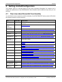
4.1 Overview about Essential Functionality .......................................................................................36
4.2 Configuration Procedures ............................................................................................................37
4.2.1 Using a Packet ................................................................................................................................ 37
4.3
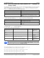
Warmstart Parameters .................................................................................................................38
4.3.1 Behavior when receiving a Set Configuration / Warmstart Command ............................................. 40
4.4
4.5
5
Process Data (Input and Output) .................................................................................................40
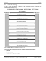
Task Structure of the PROFIBUS DP Slave Stack ......................................................................41
Overview................................................................................................................................................43
5.1 Classification of PROFIBUS-DP Devices ....................................................................................43
5.1.1 DP Master Class 1 .......................................................................................................................... 43
5.1.2 DP Master Class 2 .......................................................................................................................... 43
5.1.3 DP Slave ......................................................................................................................................... 43
5.2
Operation Modes..........................................................................................................................44
5.2.1 Operation Modes of PROFIBUS DP Masters .................................................................................. 44
5.2.2 Operation Modes of Profibus DP Slaves ......................................................................................... 44
5.3
Commissioning.............................................................................................................................47
5.3.1 Diagnosis......................................................................................................................................... 48
5.3.2 Parameterization ............................................................................................................................. 52
5.3.3 Configuration of Inputs and Outputs ................................................................................................ 54
PROFIBUS-DP Slave | Protocol API
DOC050401API15EN | Revision 15 | English | 2013-09 | Released | Public
© Hilscher, 2005-2013
Introduction
5.4
5.5
3/238
Cyclic Data Transfer.....................................................................................................................59
Acyclic Data Transfer ...................................................................................................................61
5.5.1 Acyclic Data Transfer of the DP Master Class 1.............................................................................. 61
5.5.2 Acyclic Data Transfer of the DP Master Class 2.............................................................................. 63
5.6
6
Alarm Processing .........................................................................................................................68
The Application Interface ....................................................................................................................70
6.1 The APS task ...............................................................................................................................70
6.1.1
6.1.2
6.1.3
6.1.4
6.1.5
6.2
PROFIBUS_APS_SET_CONFIGURATION_REQ/CNF - Set Configuration Parameters ................... 71
PROFIBUS_APS_CHECK_USER_PRM_IND/RES - Check User Parameter Data ............................. 75
PROFIBUS_APS_CHECK_CFG_IND/RES - Check Configuration Data ............................................ 78
PROFIBUS_APS_GET_USER_PRM_REQ/CNF - Request User Parameter Data .............................. 81
PROFIBUS_APS_GET_CFG_REQ/CNF - Request Config Data ........................................................ 83
The FSPMS Task.........................................................................................................................85
6.2.1 PROFIBUS_FSPMS_CMD_INIT_MS0_REQ/CNF – Initializing the MSCY1S State Machine ........... 88
6.2.2 PROFIBUS_FSPMS_CMD_INIT_MS1_REQ/CNF – Initializing the MSAC1S State Machine ........... 93
6.2.3 PROFIBUS_FSPMS_CMD_INIT_MS2_REQ/CNF – Initializing the MSAC2S State Machine ............ 98
6.2.4 PROFIBUS_FSPMS_CMD_ABORT_REQ/CNF – Send an Abort Signal ............................................ 102
6.2.5 PROFIBUS_FSPMS_CMD_SET_CFG_REQ/CNF – Setting new I/O Is-Configuration Data .............. 104
6.2.6 PROFIBUS_FSPMS_CMD_SET_SLAVE_DIAG_REQ/CNF – Transmitting Diagnostic Data............. 108
6.2.7 PROFIBUS_FSPMS_CMD_SET_INPUT_REQ/CNF – Setting the Input Data ................................. 112
6.2.8 PROFIBUS_FSPMS_CMD_GET_OUTPUT_REQ/CNF – Getting the latest Output Data................... 115
6.2.9 PROFIBUS_FSPMS_CMD_NEW_OUTPUT_IND – Indicating the Reception of new cyclic Output Data118
6.2.10 PROFIBUS_FSPMS_CMD_RESET_REQ/CNF – Request for resetting the Slave............................. 120
6.2.11 PROFIBUS_FSPMS_CMD_APPLICATION_READY_REQ/CNF – Declaring the Application ready for
Duty 122
6.2.12 PROFIBUS_FSPMS_CMD_SET_SLAVE_ADD_IND – Indicating the Reception of a Change Slave
Address Request ...................................................................................................................................... 125
6.2.13 PROFIBUS_FSPMS_CMD_GLOBAL_CONTROL_IND – Indicating a Global Control Command ....... 127
6.2.14 PROFIBUS_FSPMS_CMD_CHECK_CFG_IND/RES – Indicating the Request for Validation of the
assumed I/O Configuration Data............................................................................................................... 130
6.2.15 PROFIBUS_FSPMS_CMD_CHECK_USER_PRM_IND/RES – Indicating the Reception of new
Parameter Data ........................................................................................................................................ 134
6.2.16 PROFIBUS_FSPMS_CMD_CHECK_EXT_USER_PRM_IND/RES – Indicating new Extended
Parameter Data ........................................................................................................................................ 138
6.2.17 PROFIBUS_FSPMS_CMD_C1_READ_IND/RES_POS/RES_NEG – Indicating an acyclic read
Request to a specific Process Data Object............................................................................................... 141
6.2.18 PROFIBUS_FSPMS_CMD_C1_WRITE_IND/RES_POS/RES_NEG – Indicating an acyclic write
Request to a specific Process Data Object............................................................................................... 146
6.2.19 PROFIBUS_FSPMS_CMD_C1_ALARM_NOTIFICATION_REQ/CNF – Request Command for Alarm
Notification................................................................................................................................................ 151
6.2.20 PROFIBUS_FSPMS_CMD_C1_ALARM_ACK_IND/RES_POS/ RES_NEG – Indicating an Alarm
Request .................................................................................................................................................... 155
6.2.21 PROFIBUS_FSPMS_CMD_C2_INITIATE_IND/RES_POS/RES_NEG – Indicating a Request to
establish an acyclic Connection to a DP-Master Class 2.......................................................................... 160
6.2.22 PROFIBUS_FSPMS_CMD_C2_READ_IND/RES_POS/RES_NEG – Indicating an acyclic read
Request (Class 2) to a specific Process Data Object ............................................................................... 167
6.2.23 PROFIBUS_FSPMS_CMD_C2_WRITE_IND/RES_POS/RES_NEG – Indicating an acyclic write
Request to a specific Process Data Object............................................................................................... 171
6.2.24 PROFIBUS_FSPMS_CMD_C2_DATA_TRANSPORT_IND/RES_POS/RES_NEG – Indicating an acyclic
Data Transport Request to a single combined Process Data Object ........................................................ 176
6.2.25 PROFIBUS_FSPMS_CMD_C2_ABORT_IND/RES –Indicating the Abort of Class 2 Connection...... 181
6.2.26 PROFIBUS_FSPMS_CMD_STATE_CHANGED_IND – Indication for Change of State ...................... 185
6.2.27 PROFIBUS_FSPMS_CMD_REGISTER_DIAG_STRUCT_REQ/CNF – Request for Registration of
Diagnostic Structure ................................................................................................................................. 188
6.2.28 PROFIBUS_FSPMS_CMD_IND_SETTING_REQ/CNF - Request for deactivating the Output Indication190
6.2.29 PROFIBUS_FSPMS_CMD_STARTED_IND – Start Indication .......................................................... 192
6.2.30 PROFIBUS_FSPMS_CMD_SET_STAT_DIAG_REQ/CNF – Set Static Diagnostic............................ 193
6.2.31 PROFIBUS_FSPMS_CMD_SET_IM0_REQ/CNF – Change I&M0 Parameter Settings .................... 195
6.2.32 PROFIBUS_FSPMS_CMD_IM_READ_IND/RES – I&M Read Indication/Response ........................ 200
6.2.33 PROFIBUS_FSPMS_CMD_IM_WRITE_IND/RES - I&M Write Indication/Response ....................... 203
6.2.34 PROFIBUS_FSPMS_CMD_IOL_CALL_REGISTER_REQ/CNF – Register IO-Link Call ................... 206
6.2.35 PROFIBUS_FSPMS_CMD_IOL_CALL_IND/RES_POS/RES_NEG – IO-Link Call Indication ....... 209
6.3
Hardware Switches for the Adjustment of Slave Address and Baudrate...................................215
6.3.1 RCX_SET_HW_SWITCH_VALUES_REQ/CNF – Set the values of the Hardware Switch ................. 217
PROFIBUS-DP Slave | Protocol API
DOC050401API15EN | Revision 15 | English | 2013-09 | Released | Public
© Hilscher, 2005-2013
Introduction
7
4/238
Status/Error Codes Overview............................................................................................................220
7.1 Error Codes of the FSPMS-Task ...............................................................................................220
7.1.1 Diagnostic Codes of the FSPMS-Task .......................................................................................... 223
7.2
Error Codes of the DL-Task .......................................................................................................226
7.2.1 Diagnostic Codes of the DL-Task .................................................................................................. 228
7.3
Error Codes of the APS-Task.....................................................................................................229
7.3.1 Diagnostic Codes of the APS-Task ............................................................................................... 230
8
Appendix .............................................................................................................................................234
8.1 List of Tables..............................................................................................................................234
8.2 List of Figures.............................................................................................................................236
8.3 Contacts .....................................................................................................................................238
PROFIBUS-DP Slave | Protocol API
DOC050401API15EN | Revision 15 | English | 2013-09 | Released | Public
© Hilscher, 2005-2013
Introduction
1
1.1
5/238
Introduction
About this Document
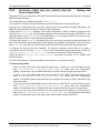
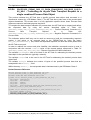
This manual describes the application interface of the Profibus-DP Slave Stack implementation on
the netX chip. The aim of this manual is to support the integration of devices based on the netX
chip into own applications based on driver functions or direct access to the dual-port memory.
The general mechanism of data transfer, for example how to send and receive a packet or how to
perform a warmstart is independent from the protocol. These procedures are common to all
devices and are described in the ‘netX DPM Interface manual’.
PROFIBUS-DP Slave | Protocol API
DOC050401API15EN | Revision 15 | English | 2013-09 | Released | Public
© Hilscher, 2005-2013
Introduction
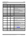
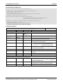
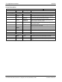
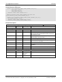
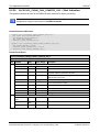
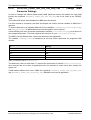
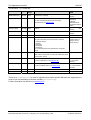
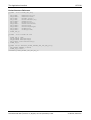
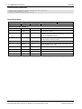
1.2
6/238
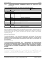
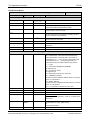
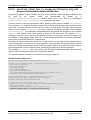
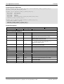
List of Revisions
Rev
Date
Name
Chapter Revision
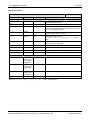
10
2010-05-12
RG/HH
Section PROFIBUS_FSPMS_CMD_STATE_CHANGED_IND – Indication for
Change of State completely rewritten
Extended section on task structure with descriptions of single tasks.
Added information of suitability of packets for LFW or LOM approach.
Corrected Configuration Data in Table 33: Meaning and allowed Values for
Warmstart-Parameters.
Section Technical Data: DMA support for PCI targets, Slot number added
Firmware/stack version V2.3.x.
Reference to netX Dual-Port Memory Interface Manual Revision 9.
11
2010-10-29
RG/RH
Firmware/stack version V2.3.32.x
Added description of 2 new flags in Warm-Start Parameters
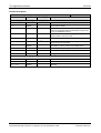
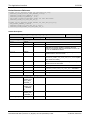
12
2012-01-26
RG/FM/
HH/MPr
Firmware/stack version V2.4.12.x
Reference to netX Dual-Port Memory Interface Manual Revision 12.
Description of 3 I&M packets added
Added section 6.3“Hardware Switches for the Adjustment of Slave Address
and Baudrate”. Adapted description of system flags accordingly.
Adapted section “Cyclic Data (Input/Output Data)” for netX devices with 8
kByte Dual-port Memory.
abCfgData in warmstart packet is 244, not 32
Corrections in Identifier Byte for the General Format, Identifier Byte for the
Special Format, Length Byte and Reason Code.
Correction of structure name
PROFIBUS_APS_PACKET_SET_CONFIGURATION_REQ_T
Removed data part of packet in section 6.2.3
Update of section “References”
Update of section “Technical Data” due to change in limitations (I & M)
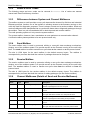
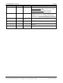
13
2013-02-20
RG/MPr
Firmware/stack version V2.6.2.x
Reference to netX Dual-Port Memory Interface Manual Revision 12.
Corrections in section “PROFIBUS_FSPMS_CMD_SET_IM0_REQ/CNF –
Change I&M0 Parameter Settings”
Added a note to descriptions of
PROFIBUS_APS_CHECK_USER_PRM_IND/RES and
PROFIBUS_APS_CHECK_CFG_IND/RES
Corrections in section 4.3.1“Behavior when receiving a Set Configuration /
Warmstart Command”
New table layout in “Diagnosis” section
New table layout in packet descriptions
Removed descriptions of deprecated packets
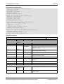
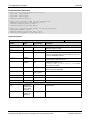
14
2013-05-27
RG/MPr
Firmware/stack version V2.6.5.x
Reference to netX Dual-Port Memory Interface Manual Revision 12.
Added info on LFW or LOM support for most packets
Updated and extended Table 68: Overview over the Packets of the FSPMS Task of the PROFIBUS DP Slave Protocol Stack
6
6.2
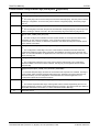
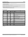
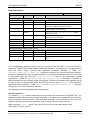
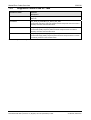
15
2013-09-06
HH/RG/
MPr
1.5
4.2.1
6.2.31
6.2.34,
6.2.35
Firmware/stack version V2.7.1.x
Reference to netX Dual-Port Memory Interface Manual Revision 12.
Added netX10 and netX51 support in “Technical Data”
Missing configuration possibility via SYCON.net mentioned
Some corrections
Added descriptions of two new packets
PROFIBUS_FSPMS_CMD_IOL_CALL_REGISTER_REQ/CNF and
PROFIBUS_FSPMS_CMD_IOL_CALL_IND/RES_POS/RES_NEG
Table 1: List of Revisions
PROFIBUS-DP Slave | Protocol API
DOC050401API15EN | Revision 15 | English | 2013-09 | Released | Public
© Hilscher, 2005-2013
Introduction
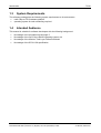
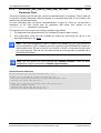
1.3
7/238
System Requirements
The software package has the following system requirements to its environment:
netX-Chip as CPU hardware platform
operating system for task scheduling required
1.4
Intended Audience
This manual is suitable for software developers with the following background:
Knowledge of the programming language C
Knowledge of the use of the realtime operating system rcX
Knowledge of the Hilscher Task Layer Reference Model
Knowledge of the IEC 61158 specification
PROFIBUS-DP Slave | Protocol API
DOC050401API15EN | Revision 15 | English | 2013-09 | Released | Public
© Hilscher, 2005-2013
Introduction
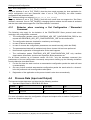
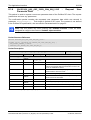
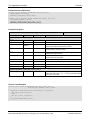
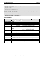
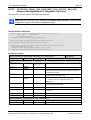
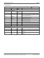
1.5
8/238
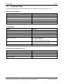
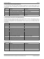
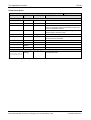
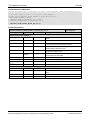
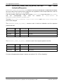
Technical Data
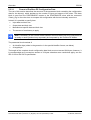
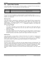
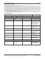
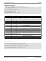
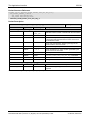
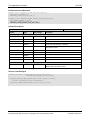
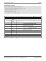
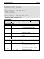
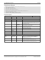
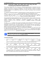
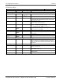
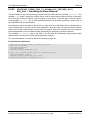
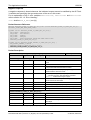
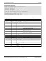
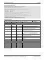
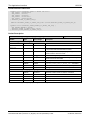
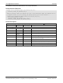
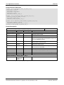
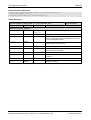
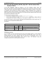
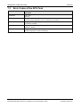
The data below applies to the PROFIBUS-DP slave firmware and stack version V2.7.x.x.
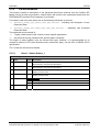
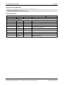
Supported State Machines
Name
State Machine
FSPMS
Fieldbus Service Protocol Slave state machine
MSCY1S
Master to Slave cyclic state machine
DMPMS
Data Link Mapping Protocol Slave state machine
MSAC1S
Master Class1 to Slave acyclic state machine
MSAC2S
Master Class2 to Slave acyclic state machine
MSRM2S
Master Class2 to Slave resource Manager state machine
Table 2: Technical Data – Supported State Machine
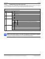
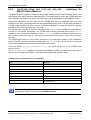
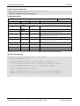
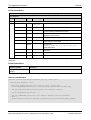
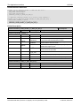
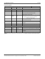
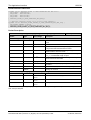
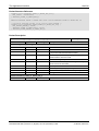
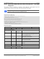
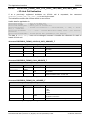
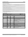
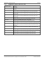
Technical Data
Features
Parameter
Maximum number of cyclic input data
244 Bytes
Maximum number of cyclic output data
244 Bytes
Maximum number of acyclic read/write
240 Bytes
Configuration data
Max. 244 bytes
Parameter data
237 bytes application specific parameters
Acyclic communication
DP V1 Class 1 Read/Write
DP V1 Class 1 Alarm
DP V1 Class 2 Read/Write/Data Transport
Baud rate
Fixed values ranging from 9,6 kBits/s to 12 MBit/s
Automatic baud rate detection is supported
Data transport layer
PROFIBUS FDL
Table 3: Technical Data - Protocol Stack
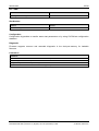
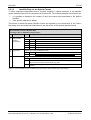
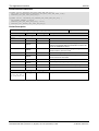
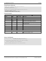
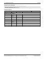
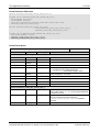
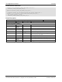
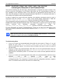
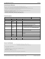
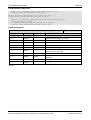
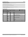
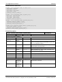
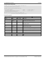
Firmware/stack available for netX
netX
Available
netX 10
yes
netX 50
yes
netX 51
yes
netX 100, netX 500
yes
Table 4: Technical Data – Available for netX
PROFIBUS-DP Slave | Protocol API
DOC050401API15EN | Revision 15 | English | 2013-09 | Released | Public
© Hilscher, 2005-2013
Introduction
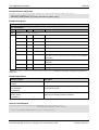
9/238
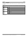
PCI - DMA
Features
Parameter
DMA Support for PCI targets
yes
Table 5: Technical Data – PCI-DMA
Slot Number
Features
Devices
Slot number supported for
CIFX 50-DP
Table 6: Technical Data – Slot Number
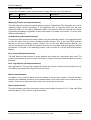
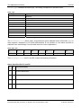
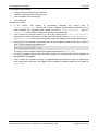
Configuration
Configuration by packets to transfer warm start parameters or by using SYCON.net configuration
database.
Diagnostic
Firmware supports common and extended diagnostic in the dual-port-memory for loadable
firmware.
Limitations
Limitations
SSCY1S – Slave to slave communication state machine not implemented.
Data exchange broadcast not implemented.
Configuration by database not implemented yet.
I&M LR services other than Call-REQ/RES are not supported yet.
Table 7: Technical Data – Limitations
PROFIBUS-DP Slave | Protocol API
DOC050401API15EN | Revision 15 | English | 2013-09 | Released | Public
© Hilscher, 2005-2013
Introduction
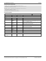
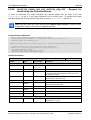
1.6
10/238
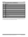
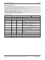
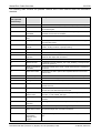
Terms, Abbreviations and Definitions
Term
Description
AP
Application on top of the Stack
AREP
Application Reference end point
MS0
Master to Slave cyclic communication
MS1
Master (class1) to Slave acyclic communication
MS2
Master (class2) to Slave acyclic communication
DL
Data Link Layer
DMPMS
Data Link Layer Protocol Machine Slave
DP
Decentralized Periphery
DPM
Dual Port Memory
FSPMS
Fieldbus Service Protocol Machine Slave
I&M
Identification & Maintenance
LSB
Least Significant Byte
MSAC1S
Master Class1 to Slave acyclic State Machine
MSAC2S
Master Class2 to Slave acyclic State Machine
MSB
Most Significant Byte
MSCY1S
Master slave cyclic state machine
PDU
Protocol Data Unit
PLC
Programmable Logic Controller
PROFIBUS
Process Fieldbus
RM
Resource Manager
Table 8: Terms, Abbreviations and Definitions
All variables, parameters, and data used in this manual have the LSB/MSB (“Intel”) data format.
This corresponds to the convention of the Microsoft C Compiler.
PROFIBUS-DP Slave | Protocol API
DOC050401API15EN | Revision 15 | English | 2013-09 | Released | Public
© Hilscher, 2005-2013
Introduction
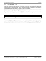
1.7
11/238
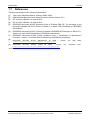
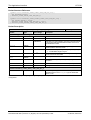
References
This document based on the following specification:
[1]
Task Layer Reference Manual, Hilscher GmbH, 2005
[2]
DPM Interface Manual for netX based Products; Hilscher GmbH; 2011
[3]
IEC 61158-5-3 Edition 2.0, August 2010
[4]
IEC 61158-6-3 Edition 2.0, August 2010
[5]
PROFIBUS document #0.032: Normative Parts of Profibus-FMS,-DP, -PA according to the
European Standard EN 50170 Volume 2 Edition 1.0, March 1998 (Published by PROFIBUS
International)
[6]
PROFIBUS document #2.082: Technical Guideline PROFIBUS-DP Extensions to EN 50170 Version 2.0, April 1998 (Published by PROFIBUS International)
[7]
PROFIBUS document #3.502: Profile Guidelines Part 1: Identification & Maintenance
Functions - Version 1.2 October 2009 (Published by PROFIBUS International)
[8]
PROFIBUS
document
#6.012:
Manufacturer
ID
Table
-
Version
May
2009,
November
2011,
V61,
http://www.profibus.com/IM/Man_ID_Table.xml
[9]
PROFIBUS
document
#6.022:
Profile
ID
Table
-
Version
V11,
http://www.profibus.com/IM/Profile_ID_Table.xml
Table 9: References
PROFIBUS-DP Slave | Protocol API
DOC050401API15EN | Revision 15 | English | 2013-09 | Released | Public
© Hilscher, 2005-2013
Introduction
1.8
1.8.1
©
12/238
Legal Notes
Copyright
2005-2013 Hilscher Gesellschaft für Systemautomation mbH
All rights reserved.
The images, photographs and texts in the accompanying material (user manual, accompanying
texts, documentation, etc.) are protected by German and international copyright law as well as
international trade and protection provisions. You are not authorized to duplicate these in whole or
in part using technical or mechanical methods (printing, photocopying or other methods), to
manipulate or transfer using electronic systems without prior written consent. You are not permitted
to make changes to copyright notices, markings, trademarks or ownership declarations. The
included diagrams do not take the patent situation into account. The company names and product
descriptions included in this document may be trademarks or brands of the respective owners and
may be trademarked or patented. Any form of further use requires the explicit consent of the
respective rights owner.
1.8.2
Important Notes
The user manual, accompanying texts and the documentation were created for the use of the
products by qualified experts, however, errors cannot be ruled out. For this reason, no guarantee
can be made and neither juristic responsibility for erroneous information nor any liability can be
assumed. Descriptions, accompanying texts and documentation included in the user manual do
not present a guarantee nor any information about proper use as stipulated in the contract or a
warranted feature. It cannot be ruled out that the user manual, the accompanying texts and the
documentation do not correspond exactly to the described features, standards or other data of the
delivered product. No warranty or guarantee regarding the correctness or accuracy of the
information is assumed.
We reserve the right to change our products and their specification as well as related user
manuals, accompanying texts and documentation at all times and without advance notice, without
obligation to report the change. Changes will be included in future manuals and do not constitute
any obligations. There is no entitlement to revisions of delivered documents. The manual delivered
with the product applies.
Hilscher Gesellschaft für Systemautomation mbH is not liable under any circumstances for direct,
indirect, incidental or follow-on damage or loss of earnings resulting from the use of the information
contained in this publication.
PROFIBUS-DP Slave | Protocol API
DOC050401API15EN | Revision 15 | English | 2013-09 | Released | Public
© Hilscher, 2005-2013
Introduction
1.8.3
13/238
Exclusion of Liability
The software was produced and tested with utmost care by Hilscher Gesellschaft für
Systemautomation mbH and is made available as is. No warranty can be assumed for the
performance and flawlessness of the software for all usage conditions and cases and for the
results produced when utilized by the user. Liability for any damages that may result from the use
of the hardware or software or related documents, is limited to cases of intent or grossly negligent
violation of significant contractual obligations. Indemnity claims for the violation of significant
contractual obligations are limited to damages that are foreseeable and typical for this type of
contract.
It is strictly prohibited to use the software in the following areas:
for military purposes or in weapon systems;
for the design, construction, maintenance or operation of nuclear facilities;
in air traffic control systems, air traffic or air traffic communication systems;
in life support systems;
in systems in which failures in the software could lead to personal injury or injuries leading to
death.
We inform you that the software was not developed for use in dangerous environments requiring
fail-proof control mechanisms. Use of the software in such an environment occurs at your own risk.
No liability is assumed for damages or losses due to unauthorized use.
1.8.4
Export
The delivered product (including the technical data) is subject to export or import laws as well as
the associated regulations of different counters, in particular those of Germany and the USA. The
software may not be exported to countries where this is prohibited by the United States Export
Administration Act and its additional provisions. You are obligated to comply with the regulations at
your personal responsibility. We wish to inform you that you may require permission from state
authorities to export, re-export or import the product.
PROFIBUS-DP Slave | Protocol API
DOC050401API15EN | Revision 15 | English | 2013-09 | Released | Public
© Hilscher, 2005-2013
Fundamentals
2
2.1
14/238
Fundamentals
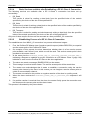
General Access Mechanisms on netX Systems
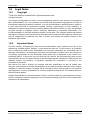
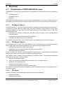
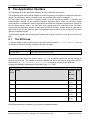
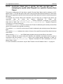
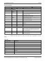
This chapter explains the possible ways to access a Protocol Stack running on a netX system:
1.
By accessing the Dual Port Memory Interface directly or via a driver.
2.
By accessing the Dual Port Memory Interface via a shared memory.
3.
By interfacing with the Stack Task of the Protocol Stack.
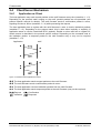
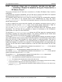
The picture below visualizes these three ways:
Figure 1: The 3 different ways to access a Protocol Stack running on a netX System
This chapter explains how to program the stack (alternative 3) correctly while the next chapter
describes accessing the protocol stack via the dual-port memory interface according to alternative
1 (and 2, if the user application is executed on the netX chip in the context of the rcX operating
system and uses the shared DPM). Finally, chapter The Application Interface on 70 page
describes the entire interface to the protocol stack in detail.
Depending on you choose the stack-oriented approach or the Dual Port Memory-based approach;
you will need either the information given in this chapter or those of the next chapter to be able to
work with the set of functions described in chapter The Application Interface on page 70. All of
those functions use the four parameters ulDest, ulSrc, ulDestId and ulSrcId. This
chapter and the next one inform about how to work with these important parameters.
PROFIBUS-DP Slave | Protocol API
DOC050401API15EN | Revision 15 | English | 2013-09 | Released | Public
© Hilscher, 2005-2013
Fundamentals
2.2
15/238
Accessing the Protocol Stack by Programming the AP
Task’s Queue
In general, programming the AP task or the stack has to be performed according to the rules
explained in the Hilscher Task Layer Reference Manual. There you can also find more information
about the variables discussed in the following.
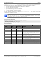
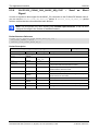
2.2.1
Getting the Receiver Task Handle of the Process Queue
To get the handle of the process queue of the PROFIBUS DP Slave Device AP--Task the Macro
TLR_QUE_IDENTIFY() needs to be used. It is described in detail within section 10.1.9.3 of the
Hilscher Task Layer Reference Model Manual. This macro delivers a pointer to the handle of the
intended queue to be accessed (which is returned within the third parameter, phQue), if you
provide it with the name of the queue (and an instance of your own task). The correct ASCII-queue
names for accessing the PROFIBUS DP Slave Device AP--Task which you have to use as current
value for the first parameter (pszIdn) is
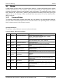
ASCII Queue name
Description
"PB_FSPMS_QUE”
Name of the FSPMS task process queue
"PB_APS_QUE”
Name of the APS task process queue
Table 10: Names of Queues in PROFIBUS DP Slave Firmware
The returned handle has to be used as value ulDest in all initiator packets the AP-Task intends to
send to the PB_FSPMS-Task. This handle is the same handle that has to be used in conjunction
with the macros like TLR_QUE_SENDPACKET_FIFO/LIFO() for sending a packet to the
respective task.
2.2.2
Meaning of Source- and Destination-related Parameters
The meaning of the source- and destination-related parameters is explained in the following table:
Variable
Meaning
ulDest
Application mailbox used for confirmation
ulSrc
Queue handle returned by TLR_QUE_IDENTIFY() as described above.
ulSrcId
Used for addressing at a lower level
Table 11: Meaning of Source- and Destination-related Parameters.
For more information about programming the AP task’s stack queue, please refer to [1]. Especially
the following sections might be of interest in this context:
1.
Chapter 7 “Queue-Packets”
2.
Section 10.1.9 “Queuing Mechanism”
PROFIBUS-DP Slave | Protocol API
DOC050401API15EN | Revision 15 | English | 2013-09 | Released | Public
© Hilscher, 2005-2013
Fundamentals
2.3
16/238
Accessing the Protocol Stack via the Dual Port Memory
Interface
This chapter defines the application interface of the PROFIBUS-DP Slave Stack.
2.3.1
Communication via Mailboxes
The mailbox of each communication channel has two areas that are used for non-cyclic message
transfer to and from the netX.
Send Mailbox
Packet transfer from host system to netX firmware
Receive Mailbox
Packet transfer from netX firmware to host system
For more details about acyclic data transfer via mailboxes see section 3.2. Acyclic Data
(Mailboxes) in this context, is described in detail in section 3.2.1 “General Structure of Messages or
Packets for Non-Cyclic Data Exchange” while the possible codes that may appear are listed in
section 3.2.2. “Status & Error Codes”.
However, this section concentrates on correct addressing the mailboxes.
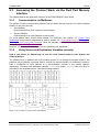
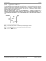
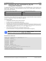
2.3.2
Using Source and Destination Variables correctly
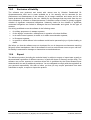
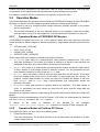
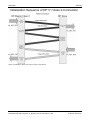
How to use ulDest for Addressing rcX and the netX Protocol Stack by the System and
Channel Mailbox
The preferred way to address the netX operating system rcX is through the system mailbox; the
preferred way to address a protocol stack is through its channel mailbox. All mailboxes, however,
have a mechanism to route packets to a communication channel or the system channel,
respectively. Therefore, the destination identifier ulDest in a packet tHeader has to be filled in
according to the targeted receiver. See the following example:
Figure 2: Use of ulDest in Channel and System Mailbox
PROFIBUS-DP Slave | Protocol API
DOC050401API15EN | Revision 15 | English | 2013-09 | Released | Public
© Hilscher, 2005-2013
Fundamentals
17/238
For use in the destination queue handle, the tasks have been assigned to hexadecimal numerical
values as described in the following table:
ulDest
Description
0x00000000
Packet is passed to the netX operating system rcX
0x00000001
Packet is passed to communication channel 0
0x00000002
Packet is passed to communication channel 1
0x00000003
Packet is passed to communication channel 2
0x00000004
Packet is passed to communication channel 3
0x00000020
Packet is passed to communication channel of the mailbox
else
Reserved, do not use
Table 12: Meaning of Destination-Parameter ulDest
The figure and the table above both show the use of the destination identifier ulDest.
A remark on the special channel identifier 0x00000020 (= Channel Token). The Channel Token is
valid for any mailbox. That way the application uses the same identifier for all packets without
actually knowing which mailbox or communication channel is applied. The packet stays 'local'. The
system mailbox is a little bit different, because it is used to communicate to the netX operating
system rcX. The rcX has its own range of valid commands codes and differs from a communication
channel.
Unless there is a reply packet, the netX operating system returns it to the same mailbox the
request packet went through. Consequently, the host application has to return its reply packet to
the mailbox the request was received from.
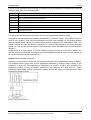
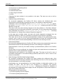
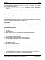
How to use ulSrc and ulSrcId
Generally, a netX protocol stack can be addressed through its communication channel mailbox.
The example below shows how a host application addresses a protocol stack running in the
context of a netX chip. The application is identified by a number (#444 in this example). The
application consists of three processes identified by the numbers #11, #22 and #33. These
processes communicate through the channel mailbox with the AP task of the protocol stack. Have
a look at the following figure:
Figure 3: Using ulSrc and ulSrcId
PROFIBUS-DP Slave | Protocol API
DOC050401API15EN | Revision 15 | English | 2013-09 | Released | Public
© Hilscher, 2005-2013
Fundamentals
18/238
Example:
This example applies to command messages initiated by a process in the context of the host
application. If the process #22 sends a packet through the channel mailbox to the AP task, the
packet tHeader has to be filled in as follows:
Variable
Numeric
Name
Value
Destination
Queue Handle
ulDest
= 32
Source Queue
Handle
Object
Description
(0x00000020)
This value needs always to be set to 0x00000020 (the channel
token) when accessing the protocol stack via the local
communication channel mailbox.
ulSrc
= 444
Denotes the host application (#444).
Destination
Identifier
ulDestId
=0
In this example it is not necessary to use the destination identifier.
Source Identifier
ulSrcId
= 22
Denotes the process number of the process within the host
application and needs therefore to be supplied by the programmer
of the host application.
Table 13: Example for correct Use of Source- and Destination-related Parameters
For packets through the channel mailbox, the application uses 32 (= 0x20, Channel Token) for the
destination queue handler ulDest. The source queue handler ulSrc and the source identifier ulSrcId
are used to identify the originator of a packet. The destination identifier ulDestId can be used to
address certain resources in the protocol stack. It is not used in this example. The source queue
handler ulSrc has to be filled in. Therefore its use is mandatory; the use of ulSrcId is optional.
The netX operating system passes the request packet to the protocol stack's AP task. The protocol
stack then builds a reply to the packet and returns it to the mailbox. The application has to make
sure that the packet finds its way back to the originator (process #22 in the example).
How to Route rcX Packets
To route an rcX packet the source identifier ulSrcId and the source queues handler ulSrc in the
packet tHeader hold the identification of the originating process. The router saves the original
handle from ulSrcId and ulSrc. The router uses a handle of its own choices for ulSrcId and ulSrc
before it sends the packet to the receiving process. That way the router can identify the
corresponding reply packet and matches the handle from that packet with the one stored earlier.
Now the router replaces its handles with the original handles and returns the packet to the
originating process.
PROFIBUS-DP Slave | Protocol API
DOC050401API15EN | Revision 15 | English | 2013-09 | Released | Public
© Hilscher, 2005-2013
Fundamentals
2.3.3
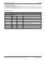
19/238
Obtaining Information about the Communication Channel
A communication channel represents a part of the Dual Port Memory and usually consists of the
following elements:
Output Data Image - is used to transfer cyclic process data to the network (normal or highpriority)
Input Data Image - is used to transfer cyclic process data from the network (normal or highpriority)
Send Mailbox - is used to transfer non-cyclic data to the netX
Receive Mailbox - is used to transfer non-cyclic data from the netX
Control Block - allows the host system to control certain channel functions
Common Status Block - holds information common to all protocol stacks
Extended Status Block - holds protocol specific network status information
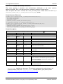
This section describes a procedure how to obtain useful information for accessing the
communication channel(s) of your netX device and to check if it is ready for correct operation.
Proceed as follows:
Start with reading the channel information block within the system channel (usually starting at
address 0x0030).
Then you should check the hardware assembly options of your netX device. They are
located within the system information block following offset 0x0010 and stored as data type
UINT16. The following table explains the relationship between the offsets and the
corresponding xC Ports of the netX device:
Value
Description
0x0010
Hardware Assembly Options for xC Port[0]
0x0012
Hardware Assembly Options for xC Port[1]
0x0014
Hardware Assembly Options for xC Port[2]
0x0016
Hardware Assembly Options for xC Port[3]
Table 14: Address Assignment of Hardware Assembly Options
Check each of the hardware assembly options whether its value has been set to
RCX_HW_ASSEMBLY_ETHERNET = 0x0080. If true, this denotes that this xC Port is suitable
for running the PROFIBUS DP slave protocol stack. Otherwise, this port is designed for
another communication protocol. In most cases, xC Port[2] will be used for field-bus
systems, while xC Port[0] and xC Port[1] are normally used for Ethernet communication.
You can find information about the corresponding communication channel (0…3) under the
following addresses:
Value
Description
0x0050
Communication Channel 0
0x0050
Communication Channel 0
0x0060
Communication Channel 1
0x0070
Communication Channel 2
0x0080
Communication Channel 3
Table 15: Addressing Communication Channel 0-3
In devices which support only one communication system which is usually the case (either a
single field-bus system or a single standard for Industrial-Ethernet communication), always
PROFIBUS-DP Slave | Protocol API
DOC050401API15EN | Revision 15 | English | 2013-09 | Released | Public
© Hilscher, 2005-2013
Fundamentals
20/238
communication channel 0 will be used. In devices supporting more than one communication
system you should also check the other communication channels.
There you can find such information as the ID (containing channel number and port number)
of the communication channel, the size and the location of the handshake cells, the overall
number of blocks within the communication channel and the size of the channel in bytes.
Evaluate this information precisely in order to access the communication channel correctly.
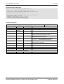
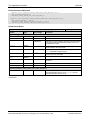
The information is delivered as follows:
Address
Data Type
Description
0x0050
UINT8
Channel Type = COMMUNICATION
(must have the fixed value
define RCX_CHANNEL_TYPE_COMMUNICATION = 0x05)
0x0051
UINT8
ID (Channel Number, Port Number)
0x0052
UINT8
Size / Position Of Handshake Cells
0x0053
UINT8
Total Number Of Blocks Of This Channel
0x0054
UINT32
Size Of Channel In Bytes
0x0058
UINT8[8]
Reserved (set to zero)
Table 16: Address Assignment of Communication Channels demonstrated at Communication Channel 0
These addresses correspond to communication channel 0, for communication channels 1, 2
and 3 you have to add an offset of 0x0010, 0x0020 or 0x0030 to the address values,
respectively.
Finally, you can access the communication channel using the addresses you determined
previously. For more information how to do this, please refer to the netX DPM Manual,
especially section 3.2 “Communication Channel".
PROFIBUS-DP Slave | Protocol API
DOC050401API15EN | Revision 15 | English | 2013-09 | Released | Public
© Hilscher, 2005-2013
Fundamentals
2.4
21/238
Client/Server Mechanism
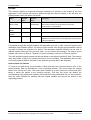
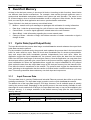
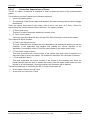
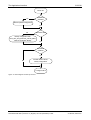
2.4.1
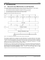
Application as Client
The host application may send request packets to the netX firmware at any time (transition 1 2).
Depending on the protocol stack running on the netX, parallel packets are not permitted (see
protocol specific manual for details). The netX firmware sends a confirmation packet in return,
signaling success or failure (transition 3 4) while processing the request.
The host application has to register with the netX firmware in order to receive indication packets
(transition 5 6). Depending on the protocol stack, this is done either implicitly or explicitly (if
application wants to receive unsolicited DPV1 packets). Details on when and how to register for
certain events is described in the protocol specific manual. Depending on the command code of
the indication packet, a response packet to the netX firmware may or may not be required
(transition 7 8).
Application
netX
Figure 4: Transition Chart Application as Client
The host application sends request packets to the netX firmware.
The netX firmware sends a confirmation packet in return.
The host application receives indication packets from the netX firmware.
The host application sends response packet to the netX firmware (may not be required).
Request
Confirmation
Indication
Response
PROFIBUS-DP Slave | Protocol API
DOC050401API15EN | Revision 15 | English | 2013-09 | Released | Public
© Hilscher, 2005-2013
Fundamentals
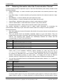
2.4.2
22/238
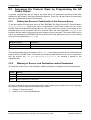
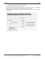
Application as Server
The host application has to register with the netX firmware in order to receive indication packets.
Depending on the protocol stack, this is done either implicitly or explicitly (if application wants to
receive unsolicited DPV1 packets). Details on when and how to register for certain events is
described in the protocol specific manual.
When an appropriate event occurs and the host application is registered to receive such a
notification, the netX firmware passes an indication packet through the mailbox (transition 1 2).
The host application is expected to send a response packet back to the netX firmware (transition 3
4).
Application
netX
Figure 5: Transition Chart Application as Server
The netX firmware passes an indication packet through the mailbox.
The host application sends response packet to the netX firmware.
Indication
Response
PROFIBUS-DP Slave | Protocol API
DOC050401API15EN | Revision 15 | English | 2013-09 | Released | Public
© Hilscher, 2005-2013
Dual-Port Memory
3
23/238
Dual-Port Memory
All data in the dual-port memory is structured in blocks. According to their functions, these blocks
use different data transfer mechanisms. For example, data transfer through mailboxes uses a
synchronized handshake mechanism between host system and netX firmware. The same is true
for IO data images, when a buffered handshake mode is configured. Other blocks, like the status
block, are read by the host application and use no synchronization mechanism.
Types of blocks in the dual-port memory are outlined below:
Mailbox - transfer non-cyclic messages or packages with a tHeader for routing information
Data Area - holds the process image for cyclic IO data or user defined data structures
Control Block - is used to signal application related state to the netX firmware
Status Block - holds information regarding the current network state
Change of State - collection of flags, that initiate execution of certain commands or signal a
change of state
3.1
Cyclic Data (Input/Output Data)
The input block holds the process data image received from the network whereas the output block
holds data sent to the network.
For the controlled / buffered mode, the protocol stack updates the process data in the internal input
buffer for each valid bus cycle. Each IO block uses handshake bits for access synchronization.
Input and output data block handshake operates independently from each other. When the
application toggles the input handshake bit, the protocol stack copies the data from the internal
buffer into the input data image of the dual-port memory. Now the application can copy data from
the dual-port memory and then give control back to the protocol stack by toggling the appropriate
input handshake bit. When the application/driver toggles the output handshake bit, the protocol
stack copies the data from the output data image of the dual-port memory into the internal buffer.
From there the data is transferred to the network. The protocol stack toggles the handshake bits
back, indicating to the application that the transfer is finished and a new data exchange cycle may
start. This mode guarantees data consistency over both input and output area.
3.1.1
Input Process Data
The input data block is used by Fieldbus and industrial Ethernet protocols that utilize a cyclic data
exchange mechanism. The input data image is used to receive cyclic data from the network.
The default size of the input data image is 5760 byte. However, not all available space is actually
used by the protocol stack. Depending on the specific protocol, the area actually available for user
data might be much smaller than 5760 byte. An input data block may or may not be available in the
dual-port memory. It is always available in the default memory map (see the netX Dual-Port
Memory Manual).
Input Data Image
Offset
Type
Name
Description
0x2680
UINT8
abPd0Input[5760]
Input Data Image: Cyclic Data From The Network
Table 17: Input Data Image (Default memory size)
PROFIBUS-DP Slave | Protocol API
DOC050401API15EN | Revision 15 | English | 2013-09 | Released | Public
© Hilscher, 2005-2013
Dual-Port Memory
24/238
For netX devices with 8 kByte Dual-port Memory, the size of the input data image is 1536 byte:
Input Data Image
Offset
Type
Name
Description
0x1600
UINT8
abPd0Input[1536]
Input Data Image: Cyclic Data From The Network
Table 18: Input Data Image for netX devices with 8 kByte Dual-port Memory
3.1.2
Output Process Data
The output data block is used by Fieldbus and industrial Ethernet protocols that utilize a cyclic data
exchange mechanism. The output data Image is used to send cyclic data from the host to the
network.
The default size of the output data image is 5760 byte. However, not all available space is actually
used by the protocol stack. Depending on the specific protocol, the area actually available for user
data might be much smaller than 5760 byte. An output data block may or may not be available in
the dual-port memory. It is always available in the default memory map (see the netX DPM
Manual).
Output Data Image
Offset
Type
Name
Description
0x1000
UINT8
abPd0Output[5760]
Output Data Image Cyclic Data To The Network
Table 19: Output Data Image (Default memory size)
For netX devices with 8 kByte Dual-port Memory, the size of the output data image is 1536 byte:
Output Data Image
Offset
Type
Name
Description
0x1000
UINT8
abPd0Output[1536]
Output Data Image Cyclic Data To The Network
Table 20: Output Data Image for netX devices with 8 kByte Dual-port Memory
3.2
Acyclic Data (Mailboxes)
The mailbox of each communication channel has two areas that are used for non-cyclic message
transfer.
Send Mailbox - packet transfer from host system to firmware
Receive Mailbox - packet transfer from firmware to host system
The send and receive mailbox areas are used by field bus protocols providing a non-cyclic data
exchange mechanism. Another use of the mailbox system is to allow access to the firmware
running on the netX chip itself for diagnostic and identification purposes. The send mailbox is used
to transfer cyclic data to the network or to the firmware. The receive mailbox is used to transfer
cyclic data from the network or from the firmware.
A send/receive mailbox may or may not be available in the communication channel. It depends on
the function of the firmware whether or not a mailbox is needed. The location of the system
mailbox and the channel mailbox is described in the netX DPM Interface Manual.
Note: Each mailbox can hold one packet at a time. The netX firmware stores packets that are not
retrieved by the host application in a packet queue. This queue has limited space and may fill up so
new packets maybe lost. To avoid these data loss situations, it is strongly recommended to empty
the mailbox frequently, even if packets are not expected by the host application. Unexpected
command packets should be returned to the sender with an Unknown Command in the status field;
unexpected reply messages can be discarded.
PROFIBUS-DP Slave | Protocol API
DOC050401API15EN | Revision 15 | English | 2013-09 | Released | Public
© Hilscher, 2005-2013
Dual-Port Memory
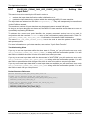
3.2.1
25/238
General Structure of Messages or Packets for Non-Cyclic Data
Exchange
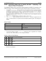
The non-cyclic packets through the netX mailbox have the following structure:
Structure Information
Variable
Type
Type of packet
Value / Range
Description
tHead - Structure Information
ulDest
UINT32
Destination Queue Handle
ulSrc
UINT32
Source Queue Handle
ulDestId
UINT32
Destination Queue Reference
ulSrcId
UINT32
Source Queue Reference
ulLen
UINT32
Packet Data Length (In Bytes)
ulId
UINT32
Packet Identification As Unique Number
ulSta
UINT32
Status / Error Code
ulCmd
UINT32
Command / Response
ulExt
UINT32
Reserved
ulRout
UINT32
Routing Information
tData - Structure Information
…
…
User Data
Specific To The Command
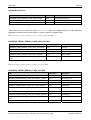
Table 21: General Structure of Packets for non-cyclic Data Exchange.
Some of the fields are mandatory; some are conditional; others are optional. However, the size of a
packet is always at least 10 double-words or 40 bytes. Depending on the command, a packet may
or may not have a data field. If present, the content of the data field is specific to the command,
respectively the reply.
Destination Queue Handle
The ulDest field identifies a task queue in the context of the netX firmware. The task queue
represents the final receiver of the packet and is assigned to a protocol stack. The ulDest field has
to be filled out in any case. Otherwise, the netX operating system cannot route the packet. This
field is mandatory.
Source Queue Handle
The ulSrc field identifies the sender of the packet. In the context of the netX firmware (inter-task
communication) this field holds the identifier of the sending task. Usually, a driver uses this field for
its own handle, but it can hold any handle of the sending process. Using this field is mandatory.
The receiving task does not evaluate this field and passes it back unchanged to the originator of
the packet.
Destination Identifier
The ulDestId field identifies the destination of an unsolicited packet from the netX firmware to the
host system. It can hold any handle that helps to identify the receiver. Therefore, its use is
mandatory for unsolicited packets. The receiver of unsolicited packets has to register for this.
PROFIBUS-DP Slave | Protocol API
DOC050401API15EN | Revision 15 | English | 2013-09 | Released | Public
© Hilscher, 2005-2013
Dual-Port Memory
26/238
Source Identifier
The ulSrcId field identifies the originator of a packet. This field is used by a host application, which
passes a packet from an external process to an internal netX task. The ulSrcId field holds the
handle of the external process. When netX operating system returns the packet, the application
can identify the packet and returns it to the originating process. The receiving task on the netX
does not evaluate this field and passes it back unchanged. For inter-task communication, this field
is not used.
Length of Data Field
The ulLen field holds the size of the data field in bytes. It defines the total size of the packet’s
payload that follows the packet’s tHeader. The size of the tHeader is not included in ulLen. So the
total size of a packet is the size from ulLen plus the size of packet’s tHeader. Depending on the
command, a data field may or may not be present in a packet. If no data field is included, the
length field is set to zero.
Identifier
The ulId field is used to identify a specific packet among others of the same kind. That way the
application or driver can match a specific reply or confirmation packet to a previous request packet.
The receiving task does not change this field and passes it back to the originator of the packet. Its
use is optional in most of the cases. But it is mandatory for sequenced packets. Example:
Downloading big amounts of data that does not fit into a single packet. For a sequence of packets
the identifier field is incremented by one for every new packet.
Status / Error Code
The ulState field is used in response or confirmation packets. It informs the originator of the packet
about success or failure of the execution of the command. The field may be also used to hold
status information in a request packet.
Command / Response
The ulCmd field holds the command code or the response code, respectively. The
command/response is specific to the receiving task. If a task is not able to execute certain
commands, it will return the packet with an error indication. A command is always even (the least
significant bit is zero). In the response packet, the command code is incremented by one indicating
a confirmation to the request packet.
Extension
The extension field ulExt is used for controlling packets that are sent in a sequenced manner. The
extension field indicates the first, last or a packet of a sequence. If sequencing is not required, the
extension field is not used and set to zero.
Routing Information
The ulRout field is used internally by the netX firmware only. It has no meaning to a driver type
application and therefore set to zero.
User Data Field
This field contains data related to the command specified in ulCmd field. Depending on the
command, a packet may or may not have a data field. The length of the data field is given in the
ulLen field.
PROFIBUS-DP Slave | Protocol API
DOC050401API15EN | Revision 15 | English | 2013-09 | Released | Public
© Hilscher, 2005-2013
Dual-Port Memory
3.2.2
27/238
Status & Error Codes
The following status and error codes can be returned in ulState. List of codes see manual
named netX Dual-Port Memory Interface.
3.2.3
Differences between System and Channel Mailboxes
The mailbox system on netX provides a non-cyclic data transfer channel for field bus and industrial
Ethernet protocols. Another use of the mailbox is allowing access to the firmware running on the
netX chip itself for diagnostic purposes. There is always a send and a receive mailbox. Send and
receive mailboxes utilize handshake bits to synchronize these data or diagnostic packages through
the mailbox. There is a pair of handshake bits for both the send and receive mailbox.
The netX operating system rcX only uses the system mailbox.
The system mailbox, however, has a mechanism to route packets to a communication channel.
A channel mailbox passes packets to its own protocol stack only.
3.2.4
Send Mailbox
The send mailbox area is used by protocols utilizing a non-cyclic data exchange mechanism.
Another use of the mailbox system is to provide access to the firmware running on the netX chip
itself. The send mailbox is used to transfer non-cyclic data to the network or to the protocol stack.
The size is 1596 bytes for the send mailbox in the default memory layout. The mailbox is
accompanied by counters that hold the number of packages that can be accepted.
3.2.5
Receive Mailbox
The receive mailbox area is used by protocols utilizing a non-cyclic data exchange mechanism.
Another use of the mailbox system is to provide access to the firmware running on the netX chip
itself. The receive mailbox is used to transfer non-cyclic data from the network or from the
protocol stack.
The size is 1596 bytes for the receive mailbox in the default memory layout. The mailbox is
accompanied by counters that hold the number of waiting packages (for the receive mailbox).
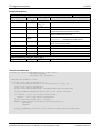
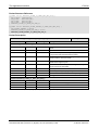
3.2.6
Channel Mailboxes (Details of Send and Receive Mailboxes)
Master Status
Offset
Type
Name
Description
0x0200
UINT16
usPackagesAccepted
Packages Accepted
Number of packages that can be accepted
0x0202
UINT16
usReserved
Reserved
Set to 0
0x0204
UINT8
abSendMbx[1596]
Send Mailbox
Non cyclic data to the network or to the protocol stack
0x0840
UINT16
usWaitingPackages
Packages waiting
Counter of packages that are waiting to be processed
0x0842
UINT16
usReserved
Reserved
Set to 0
0x0844
UINT8
abRecvMbx[1596]
Receive Mailbox
Non cyclic data from the network or from the protocol stack
Table 22: Channel Mailboxes.
PROFIBUS-DP Slave | Protocol API
DOC050401API15EN | Revision 15 | English | 2013-09 | Released | Public
© Hilscher, 2005-2013
Dual-Port Memory
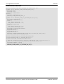
28/238
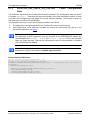
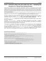
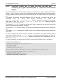
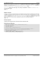
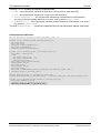
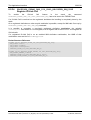
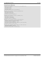
Channel Mailboxes Structure
typedef struct tagNETX_SEND_MAILBOX_BLOCK
{
UINT16 usPackagesAccepted;
UINT16 usReserved;
UINT8 abSendMbx[ 1596 ];
} NETX_SEND_MAILBOX_BLOCK;
typedef struct tagNETX_RECV_MAILBOX_BLOCK
{
UINT16 usWaitingPackages;
UINT16 usReserved;
UINT8 abRecvMbx[ 1596 ];
} NETX_RECV_MAILBOX_BLOCK;
PROFIBUS-DP Slave | Protocol API
DOC050401API15EN | Revision 15 | English | 2013-09 | Released | Public
© Hilscher, 2005-2013
Dual-Port Memory
3.3
29/238
Status
A status block is present within the communication channel. It contains information about network
and task related issues. In some respects, status and control block are used together in order to
exchange information between host application and netX firmware. The application reads a status
block whereas the control block is written by the application. Both status and control block have
registers that use the Change of State mechanism (see also section 2.2.1 of the netX Dual-PortMemory manual).
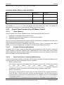
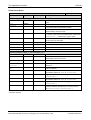
3.3.1
Common Status
The Common Status Block contains information that is the same for all communication channels.
The start offset of this block depends on the size and location of the preceding blocks. The status
block is always present in the dual-port memory.
All Implementations
The structure outlined below is common to all protocol stacks.
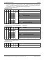
Common Status Structure Definition
Offset
Type
Name
Description
0x0010
UINT32
ulCommunicationCOS
Communication Change of State
READY, RUN, RESET REQUIRED, NEW, CONFIG
AVAILABLE, CONFIG LOCKED
0x0014
UINT32
ulCommunicationState
Communication State
NOT CONFIGURED, STOP, IDLE, OPERATE
0x0018
UINT32
ulCommunicationError
Communication Error
Unique Error Number According to Protocol Stack
0x001C
UINT16
usVersion
Version
Version Number of this Diagnosis Structure
0x001E
UINT16
usWatchdogTime
Watchdog Timeout
Configured Watchdog Time
0x0020
UINT16
usHandshakeMode
Handshake Mode
Process Data Transfer Mode (see netX DPM Interface Manual)
0x0022
UINT16
usReserved
0x0024
UINT32
ulHostWatchdog
Host Watchdog
Joint Supervision Mechanism: Protocol Stack Writes, Host
System Reads
0x0028
UINT32
ulErrorCount
Error Count
Total Number of Detected Error Since Power-Up or Reset
0x002C
UINT32
ulErrorLoglnd
Error Log Indicator
Total Number Of Entries In The Error Log Structure (not
supported yet)
0x0030
UINT32
ulReserved[2]
Reserved
Set to 0
Reserved
Set to 0
Table 23: Common Status Structure Definition
PROFIBUS-DP Slave | Protocol API
DOC050401API15EN | Revision 15 | English | 2013-09 | Released | Public
© Hilscher, 2005-2013
Dual-Port Memory
30/238
Common Status Block Structure Reference
typedef struct NETX_COMMON_STATUS_BLOCK_Ttag
{
UINT32 ulCommunicationCOS;
UINT32 ulCommunicationState;
UINT32 ulCommunicationError;
UINT16 usVersion;
UINT16 usWatchdogTime;
UINT16 ausReserved[2];
UINT32 ulHostWatchdog;
UINT32 ulErrorCount;
UINT32 ulErrorLogInd;
UINT32 ulReserved[2];
union
{
NETX_MASTER_STATUS_T tMasterStatus;
/* for master implementation */
UINT32
aulReserved[6];
/* otherwise reserved
*/
} unStackDepended;
} NETX_COMMON_STATUS_BLOCK_T;
Communication Change of State (All Implementations)
The communication change of state register contains information about the current operating
status of the communication channel and its firmware. Every time the status changes, the netX
protocol stack toggles the netX Change of State Command flag in the netX communication flags
register (see section 3.2.2.1 of the netX DPM Interface Manual). The application then has to toggle
the netX Change of State Acknowledge flag back acknowledging the new state (see section
3.2.2.2 of the netX DPM Interface Manual).
ulCommunicationCOS - netX writes, Host reads
Bit
Short name
Name
31..7
unused, set to zero
6
Restart Required Enable
RCX_COMM_COS_RESTART_REQUIRED_ENABLE
5
Restart Required
RCX_COMM_COS_RESTART_REQUIRED
4
Configuration New
RCX_COMM_COS_CONFIG_NEW
3
Configuration Locked
RCX_COMM_COS_CONFIG_LOCKED
2
Bus On
RCX_COMM_COS_BUS_ON
1
Running
RCX_COMM_COS_RUN
0
Ready
RCX_COMM_COS_READY
Table 24: Communication State of Change
PROFIBUS-DP Slave | Protocol API
DOC050401API15EN | Revision 15 | English | 2013-09 | Released | Public
© Hilscher, 2005-2013
Dual-Port Memory
31/238
Communication Change of State Flags (netX System Application)
Bit
Definition / Description
0
Ready (RCX_COMM_COS_READY)
0-…
1 - The Ready flag is set as soon as the protocol stack is started properly. Then the protocol stack is
awaiting a configuration. As soon as the protocol stack is configured properly, the Running flag is
set, too.
1
Running (RCX_COMM_COS_RUN)
0-…
1 - The Running flag is set when the protocol stack has been configured properly. Then the protocol
stack is awaiting a network connection. Now both the Ready flag and the Running flag are set.
2
Bus On (RCX_COMM_COS_BUS_ON)
0-…
1 - The Bus On flag is set to indicate to the host system whether or not the protocol stack has the
permission to open network connections. If set, the protocol stack has the permission to
communicate on the network; if cleared, the permission was denied and the protocol stack will not
open network connections.
3
Configuration Locked (RCX_COMM_COS_CONFIG_LOCKED)
0-…
1 - The Configuration Locked flag is set, if the communication channel firmware has locked the
configuration database against being overwritten. Re-initializing the channel is not allowed in this
state. To unlock the database, the application has to clear the Lock Configuration flag in the control
block (see page 35).
4
Configuration New (RCX_COMM_COS_CONFIG_NEW)
0-…
1 - The Configuration New flag is set by the protocol stack to indicate that a new configuration
became available, which has not been activated. This flag may be set together with the Restart
Required flag.
5
Restart Required (RCX_COMM_COS_RESTART_REQUIRED)
0-…
1 -The Restart Required flag is set when the channel firmware requests to be restarted. This flag is
used together with the Restart Required Enable flag below. Restarting the channel firmware may
become necessary, if a new configuration was downloaded from the host application or if a
configuration upload via the network took place.
6
Restart Required Enable (RCX_COMM_COS_RESTART_REQUIRED_ENABLE)
0-…
1 - The Restart Required Enable flag is used together with the Restart Required flag above. If set,
this flag enables the execution of the Restart Required command in the netX firmware (for details on
the Enable mechanism see section 2.3.2 of the netX DPM Interface Manual)).
7 … 31
Reserved, set to 0
Table 25: Meaning of Communication Change of State Flags
PROFIBUS-DP Slave | Protocol API
DOC050401API15EN | Revision 15 | English | 2013-09 | Released | Public
© Hilscher, 2005-2013
Dual-Port Memory
32/238
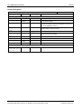
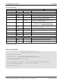
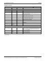
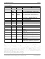
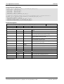
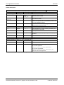
Communication State (All Implementations)
The communication state field contains information regarding the current network status of the
communication channel. Depending on the implementation, all or a subset of the definitions below
is supported.
Value
Definition
Description
0x00000000
RCX_COMM_STATE_UNKNOWN
UNKNOWN
0x00000001
RCX_COMM_STATE_NOT_CONFIGURED
NOT_CONFIGURED
0x00000002
RCX_COMM_STATE_STOP
STOP
0x00000003
RCX_COMM_STATE_IDLE
IDLE
0x00000004
RCX_COMM_STATE_OPERATE
OPERATE
Table 26: Meaning of Communication State
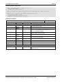
Communication Channel Error (All Implementations)
This field holds the current error code of the communication channel. If the cause of error is
resolved, the communication error field is set to zero (= RCX_SYS_SUCCESS) again. Not all of the
error codes are supported in every implementation. Protocol stacks may use a subset of the error
codes below.
Value
Definition
Description
0x00000000
RCX_SYS_SUCCESS
SUCCESS
RCX_E_WATCHDOG_TIMEOUT
WATCHDOG TIMEOUT
Runtime Failures
0xC000000C
Initialization Failures
0xC0000100
RCX_E_INIT_FAULT
(General) INITIALIZATION FAULT
0xC0000101
RCX_E_DATABASE_ACCESS_FAILED
DATABASE ACCESS FAILED
Configuration Failures
0xC0000119
RCX_E_NOT_CONFIGURED
NOT CONFIGURED
0xC0000120
RCX_E_CONFIGURATION_FAULT
(General) CONFIGURATION FAULT
0xC0000121
RCX_E_INCONSISTENT_DATA_SET
INCONSISTENT DATA SET
0xC0000122
RCX_E_DATA_SET_MISMATCH
DATA SET MISMATCH
0xC0000123
RCX_E_INSUFFICIENT_LICENSE
INSUFFICIENT LICENSE
0xC0000124
RCX_E_PARAMETER_ERROR
PARAMETER ERROR
0xC0000125
RCX_E_INVALID_NETWORK_ADDRESS
INVALID NETWORK ADDRESS
0xC0000126
RCX_E_NO_SECURITY_MEMORY
NO SECURITY MEMORY
Table 27: Meaning of Communication Channel Error
Network Failures
Value
Definition
Description
0xC0000140
RCX_COMM_NETWORK_FAULT
(General) NETWORK FAULT
0xC0000141
RCX_COMM_CONNECTION_CLOSED
CONNECTION CLOSED
0xC0000142
RCX_COMM_CONNECTION_TIMEOUT
CONNECTION TIMED OUT
0xC0000143
RCX_COMM_LONELY_NETWORK
LONELY NETWORK
0xC0000144
RCX_COMM_DUPLICATE_NODE
DUPLICATE NODE
0xC0000145
RCX_COMM_CABLE_DISCONNECT
CABLE DISCONNECT
Table 28: Meaning of Network failures
PROFIBUS-DP Slave | Protocol API
DOC050401API15EN | Revision 15 | English | 2013-09 | Released | Public
© Hilscher, 2005-2013
Dual-Port Memory
33/238
Version (All Implementations)
The version field holds version of this structure. It starts with one; zero is not defined.
Value
Definition
Description
0x0001
RCX_STATUS_BLOCK_VERSION
STRUCTURE VERSION
Table 29: Version (All Implementations)
Watchdog Timeout (All Implementations)
This field holds the configured watchdog timeout value in milliseconds. The application may set its
watchdog trigger interval accordingly. If the application fails to copy the value from the host
watchdog location to the device watchdog location, the protocol stack will interrupt all network
connections immediately regardless of their current state. For details, see section 4.13 of the netX
DPM Interface Manual.
Host Watchdog (All Implementations)
The protocol stack supervises the host system using the watchdog function. If the application fails
to copy the value from the device watchdog location (section 3.2.5 of the netX DPM Interface
Manual) to the host watchdog location (section 3.2.4 of the netX DPM Interface Manual), the
protocol stack assumes that the host system has some sort of problem and shuts down all network
connections. For details on the watchdog function, refer to section 4.13 of the netX DPM Interface
Manual.
Error Count (All Implementations)
This field holds the total number of errors detected since power-up, respectively after reset. The
protocol stack counts all sorts of errors in this field no matter if they were network related or caused
internally.
Error Log Indicator (All Implementations)
Not supported yet: The error log indicator field holds the number of entries in the internal error log.
If all entries are read from the log, the field is set to zero.
Master Implementation
In addition to the common status block as outlined in the previous section, a master firmware
maintains the additional structures for the administration of all slaves which are connected to the
master. These are not discussed here as they are not relevant for the slave.
Slave Implementation
The slave firmware uses only the common structure as outlined in section 3.2.5.1. of the netX DPM
Interface Manual. This is true for all protocol stacks.
PROFIBUS-DP Slave | Protocol API
DOC050401API15EN | Revision 15 | English | 2013-09 | Released | Public
© Hilscher, 2005-2013
Dual-Port Memory
3.3.2
34/238
Extended Status
The content of the channel specific extended status block depends on the implementation.
Depending on the protocol, a status area may or may not be present in the dual-port memory. It is
always available in the default memory map (see section 3.2.1 of netX Dual-Port Memory Manual).
Extended Status Block
Offset
Type
Name
Description
0x0300
UINT8
abExtendedStatus[432]
Extended Status Area
Protocol Stack Specific Status Area
Table 30: Extended Status Block
Extended Status Block Structure
typedef struct NETX_EXTENDED_STATUS_BLOCK_Ttag
{
UINT8 abExtendedStatus[432];
} NETX_EXTENDED_STATUS_BLOCK_T
For the Profibus DP-Slave protocol implementation, the Extended Status Area is structured as
follows:
typedef struct FSPMS_EXTENDED_DIAG_Ttag {
UINT32 ulBusAddresse;
UINT32 ulIdentNumber;
UINT32 ulBaudrate;
UINT16 usOutputLength;
UINT16 usInputLength;
} FSPMS_EXTENDED_DIAG_T;
The meaning of these parameters is:
ulBusAddresse
This value contains the own address of the Hilscher Profibus DP Slave device. The allowed
range extends from 0 to 126.
ulIdentNumber
This value contains a PROFIBUS-system specific identification number. The value is 0x0A12
indicating a netX-based system.
ulBaudrate
This value contains the baud rate of PROFIBUS connection. The coding is the one described
in Table 34: Available Baud Rate Values. The default value is “Auto-detect”.
usOutputLength
This value contains the available length for output data.
usInputLength
This value contains the available length for input data.
PROFIBUS-DP Slave | Protocol API
DOC050401API15EN | Revision 15 | English | 2013-09 | Released | Public
© Hilscher, 2005-2013
Dual-Port Memory
3.4
35/238
Control Block
A control block is always present within the communication channel. In some respects, control and
status block are used together in order to exchange information between host application and netX
firmware. The control block is written by the application, whereas the application reads a status
block. Both control and status block have registers that use the Change of State mechanism (see
also section 2.2.1 of the netX Dual-Port-Memory Manual.)
The following gives an example of the use of control and status block. The host application wishes
to lock the configuration settings of a communication channel to protect them against changes. The
application sets the Lock Configuration flag in the control block to the communication channel
firmware. As a result, the channel firmware sets the Configuration Locked flag in the status block
(see below), indicating that the current configuration settings cannot be deleted, altered,
overwritten or otherwise changed.
The control block of a dual-port memory features a watchdog function to allow the operating
system running on the netX supervise the host application and vice versa. The control area is
always present in the dual-port memory.
Control Block
Offset
Type
Name
Description
0x0008
UINT32
ulApplicationCOS
Application Change Of State
State Of The Application Program
INITIALIZATION, LOCK CONFIGURATION
0x000C
UINT32
ulDeviceWatchdog
Device Watchdog: Host System Writes, Protocol Stack Reads
Table 31: Communication Control Block
Communication Control Block Structure
typedef struct NETX_CONTROL_BLOCK_Ttag
{
UINT32 ulApplicationCOS;
UINT32 ulDeviceWatchdog;
} NETX_CONTROL_BLOCK_T;
For more information concerning the Control Block please refer to the netX DPM Interface Manual.
PROFIBUS-DP Slave | Protocol API
DOC050401API15EN | Revision 15 | English | 2013-09 | Released | Public
© Hilscher, 2005-2013
Getting started/Configuration
4
36/238
Getting started/Configuration
This chapter gives an overview where to find some important information for starters and it
explains the parameters of the PROFIBUS-DP Slave firmware and the different ways how you can
set them.
4.1
Overview about Essential Functionality
You can find the most commonly used functionality of the PROFIBUS DP slave protocol API within
the following sections of this document:
Topic
Section No.
Set Configuration
6.1.1
Cyclic data
transfer
(Input/Output)
5.4
Cyclic Data Transfer
Init
6.2.1
PROFIBUS_FSPMS_CMD_INIT_MS0_REQ/CNF – Initializing the MSCY1S State
Machine
Set Input
6.2.7
PROFIBUS_FSPMS_CMD_SET_INPUT_REQ/CNF – Setting the Input Data
6.2.8
PROFIBUS_FSPMS_CMD_GET_OUTPUT_REQ/CNF – Getting the latest Output
Data
New Output Ind.
6.2.9
PROFIBUS_FSPMS_CMD_NEW_OUTPUT_IND – Indicating the Reception of new
cyclic Output Data
Acyclic data
transfer (Records)
5.5
Acyclic Data Transfer
Init Class 1
6.2.2
PROFIBUS_FSPMS_CMD_INIT_MS1_REQ/CNF – Initializing the MSAC1S State
Machine
Init Class 2
6.2.3
PROFIBUS_FSPMS_CMD_INIT_MS2_REQ/CNF – Initializing the MSAC2S State
Machine
Get Output
2
Section Name
PROFIBUS_APS_SET_CONFIGURATION_REQ/CNF - Set Configuration
Parameters
2
Initiate Ind. Class 2 6.2.21
PROFIBUS_FSPMS_CMD_INITIATE_IND – Indicating a Request to establish an
acyclic Connection to a DP-Master Class 2
Class 1 Read
6.2.17
PROFIBUS_FSPMS_CMD_READ_IND – Indicating an acyclic read Request to a
specific Process Data Object
Class 1 Write
6.2.18
PROFIBUS_FSPMS_CMD_WRITE_IND – Indicating an acyclic write Request to a
specific Process Data Object
Class 2 Read
6.2.22
PROFIBUS_FSPMS_CMD_C2_READ_IND – Indicating an acyclic read Request
(Class 2) to a specific Process Data Object
Class 2 Write
6.2.23
PROFIBUS_FSPMS_CMD_C2_WRITE_IND – Indicating an acyclic write
Request to a specific Process Data Object
Alarm Handling
5.6
Alarm Processing
Alarm Notification
6.2.19
PROFIBUS_FSPMS_CMD_C1_ALARM_NOTIFICATION_REQ/CNF – Request
Command for Alarm Notification
Alarm
Acknowledge
6.2.20
PROFIBUS_FSPMS_CMD_C1_ALARM_ACK_IND – Indicating an Alarm
Request
Table 32: Overview about essential Functionality (Cyclic and acyclic Data Transfer and Alarm Handling).
PROFIBUS-DP Slave | Protocol API
DOC050401API15EN | Revision 15 | English | 2013-09 | Released | Public
© Hilscher, 2005-2013
Getting started/Configuration
4.2
37/238
Configuration Procedures
The following ways are available to configure the Profibus DP Slave:
By set configuration packet
By SYCON.net (for details, see according SYCON.net documentation)
By netX configuration and diagnostic utility (for details, see according documentation of the
utility)
4.2.1
Using a Packet
In order to send the set configuration parameters to the interface and to perform a warmstart
subsequently, the PROFIBUS_APS_SET_CONFIGURATION_REQ packet can be sent to the
protocol stack. For more information how to accomplish this, please refer to section
6.1.1“PROFIBUS_APS_SET_CONFIGURATION_REQ/CNF - Set Configuration Parameters” on
page 71.
PROFIBUS-DP Slave | Protocol API
DOC050401API15EN | Revision 15 | English | 2013-09 | Released | Public
© Hilscher, 2005-2013
Getting started/Configuration
4.3
38/238
Warmstart Parameters
The following table contains relevant information about the warmstart parameters for the
PROFIBUS-DP Slave firmware such as an explanation of the meaning of the parameter and
ranges of allowed values:
Parameter
Meaning
Range of Value /
Value
Application controlled
(1),
Automatic (0)
Default: Automatic (0)
Bus Startup
The start of the device can be performed either application controlled
or automatically:
Automatic:
Network connections are opened automatically without taking care of
the state of the host application.
Application controlled:
The channel firmware is forced to wait for the host application to set
the Application Ready flag in the communication change of state
register (see section 3.2.5.1 of the netX DPM Interface Manual).
For more information concerning this topic see section 4.4.1
“Controlled or Automatic Start” of the netX DPM Interface Manual.
I/O Status
(not yet supported)
0
This parameter is represented by bits 1 and 2 of the system flags.
Using this parameter you can set the status of the input or the output
data. For each input and output date the following status information (in
byte) is stored in the dual-port memory.
The bits have the following meaning:
Bit 1 (I/O Status Enable):
0 = Status disabled
1 = Status enabled (not yet supported)
Bit 2 (I/O Status 8/32Bit):
0 = 1 Byte mode (not yet supported)
1 = 4 Byte mode (not yet supported)
Address Switch
This parameter is represented by bit 4 of the system flags.
It should be set when hardware address switch is used and there is no
TAG present.
Baudrate Switch
This parameter is represented by bit 5 of the system flags.
0 (off),1 (on)
It should be set when hardware baudrate switch is used and there is no
TAG present.
Watchdog Time [ms]
Watchdog time within which the device watchdog must be retriggered
from the application program while the application program monitoring
is activated. When the watchdog time value is equal to 0 respectively
the application program monitoring is deactivated.
[0, 20 … 65535] ms,
default = 1000 ms,
0 = Off
Ident Number
PROFIBUS-system specific identification number
Generally allowed
values: 0x0 –
0xFFFF
Default value: 0x0A12
(indicating netX)
Bus Address
Bus address (own network station address)
Allowed values:
0 – 126
Baudrate
Network transmission rate (Baudrate) of the PROFIBUS connection.
Allowed values: all
baud rates offered in
Table 34: Available
Baud Rate Values.
Default value: Auto
detect
Flags
Some flags, see explanation below!
Default value: 0
Length of
Configuration Data
Number of bytes following containing configuration data
2..244
Configuration
Data[0…243]
Identifier Byte (can be specified in two alternative form):
General Identifier Byte (coded according to the Profibus standard, see
Valid identifier byte in
general or special
PROFIBUS-DP Slave | Protocol API
DOC050401API15EN | Revision 15 | English | 2013-09 | Released | Public
0 (off),1 (on)
© Hilscher, 2005-2013
Getting started/Configuration
39/238
section 5.3.3) or
Special Identifier Byte Format (SIF), see section Configuration of
Inputs and Outputs on page 54.
format
Table 33: Meaning and allowed Values for Warmstart-Parameters.
If necessary further configuration data can be specified up to index value 31.
The applicable baud rates can be coded with the values given in the following table:
Baud rate
Symbolic Constant
Value
Baud rate 9,6 kBit/s
PROFIBUS_DL_DATA_RATE_96
0
Baud rate 19,2 kBit/s
PROFIBUS_DL_DATA_RATE_19_2
1
Baud rate 93,75 kBit/s
PROFIBUS_DL_DATA_RATE_93_75
2
Baud rate 187,5 kBit/s
PROFIBUS_DL_DATA_RATE_187_5
3
Baud rate 500 kBit/s
PROFIBUS_DL_DATA_RATE_500
4
Baud rate 1,5 MBit/s
PROFIBUS_DL_DATA_RATE_1500
6
Baud rate 3 MBit/s
PROFIBUS_DL_DATA_RATE_3000
7
Baud rate 6 MBit/s
PROFIBUS_DL_DATA_RATE_6000
8
Baud rate 12 MBit/s
PROFIBUS_DL_DATA_RATE_12000
9
Baud rate 31,25 kBit/s
PROFIBUS_DL_DATA_RATE_31_25
10
Baud rate 45,45 kBit/s
PROFIBUS_DL_DATA_RATE_45_45
11
Baud rate Auto detect
PROFIBUS_DL_DATA_RATE_AUTO
15
Table 34: Available Baud Rate Values
The single bits of the flags variable have the following meaning:
Bit 0: DPV1 Enable (WRMSTRT_FLG_DPV1_ENABLE):
Flag that indicates whether DPV1 is supported. If set, DPV1 functions are activated. Otherwise,
DPV1 functions will not be available.
Bit 1: Sync supported (WRMSTRT_FLG_SYNC_SUPP):
Flag that indicates if set to TLR_TRUE(1) that the slave stack shall support the SYNC command
and the SYNC mode is activated. Otherwise, if set to TLR_FALSE(0), the slave stack will not
support the SYNC command.
Bit 2: Freeze supported (WRMSTRT_FLG_FREEZE_SUPP):
Flag that indicates if set to TLR_TRUE(1) that the slave stack shall support the FREEZE command
and the FREEZE mode is activated. Otherwise, if set to TLR_FALSE(0), the slave stack will not
support the FREEZE command.
Bit 3: ‘Fail safe’ supported (WRMSTRT_FLG_FAILSAFE_SUPP):
Flag that indicates whether ‘Fail safe’ operation is supported. If set, FAILSAFE mode is activated.
Otherwise, FAILSAFE mode will not be available.
Bit 4: ‘Alarm SAP 50 deactivate’ (WRMSTRT_FLG_NO_ALARM_SUPP):
Flag that indicates if set to TLR_TRUE (1) that the alarm SAP 50 is deactivated. If the flag is set to
TLR_FALSE(0), the stack supports the alarm SAP 50.
Bit 5: ‘I/O data swap (WRMSTRT_FLG_IO_SWAP)
Flag that indicates if the I/O Data at the Dual Port Memory is shown at Motorola or Intel format.
PROFIBUS-DP Slave | Protocol API
DOC050401API15EN | Revision 15 | English | 2013-09 | Released | Public
© Hilscher, 2005-2013
Getting started/Configuration
40/238
Bit 6: Auto configuration (WRMSTRT_FLG_AUTOCONFIG):
Flag that indicates if set to TLR_TRUE(1) that the slave stack requests the host application for
check configuration and user parameter data. If set to TLR_FALSE(0), the stack handles
configuration and parameter data.
Bit 7: Address change not allowed (WRMSTRT_FLG_NO_ADDR_CHANGE):
Flag that indicates if set to TLR_TRUE(1) that the slave stack does not support the “Set Slave
Address” command. If set to TLR_FALSE(0), changing the bus address via the master is activated
and the slave stack does support the “Set Slave Address” command
4.3.1
Behavior when receiving a Set Configuration / Warmstart
Command
The following rules apply for the behavior of the PROFIBUS-DP Slave protocol stack when
receiving a set configuration command:
The configuration packets name is PROFIBUS_APS_SET_CONFIGURATION_REQ for the
request and PROFIBUS_APS_SET_CONFIGURATION _CNF for the confirmation.
The configuration data are checked for consistency and integrity.
In case of failure all data are rejected.
In case of success the configuration parameters are stored internally (within the RAM).
The parameterized data will be activated only after a channel init has been performed.
No automatic registration of the application at the stack happens.
The confirmation packet PROFIBUS_APS_SET_CONFIGURATION_CNF only transfers
simple status information, but does not repeat the whole parameter set.
For all former versions up to firmware version V2.0.12.1, only the warmstart command (the
predecessor of the set configuration command) was present showing up the following deviations
from the behavior described above:
1.
For the first time the stack receives a warmstart/set configuration packet the stack will start
up automatically.
2.
On every further received warmstart/set configuration packet the stack waits for a channelinit to be performed until reconfiguration takes place.
3.
Registration of the application at the protocol stack is also done automatically.
4.4
Process Data (Input and Output)
The input and output data area is divided into the following sections:
Input and Output Data for PROFIBUS DP Slave
I/O Offset
Area
Length (Byte)
Type
0x1000
Output block
244
Read/Write
0x2680
Input block
244
Read
Table 35: Input and Output Data for Remote Device Station with One Occupied Stations, Single Setting
For more information about the configuration of inputs and outputs refer to section Configuration of
Inputs and Outputs on page 54.
PROFIBUS-DP Slave | Protocol API
DOC050401API15EN | Revision 15 | English | 2013-09 | Released | Public
© Hilscher, 2005-2013
Getting started/Configuration
4.5
41/238
Task Structure of the PROFIBUS DP Slave Stack
The illustration below displays the internal structure of the tasks which together represent the
PROFIBUS DP Slave Stack:
System Area
DPM
MBX
Out
MBX
In
MBX
Task
MBX
Task
Handshake Area
HC
HC
Channel Area
Channel
MBX
Out
MBX
In
MBX
Task
MBX
Task
Out
In
netX
A
B
C
A
B
rX-Idle
rX-Timer
APS-Task
rX-System
C
Triple
Buffer for
cyclic IO
Watchdog
Timer
PROFIBUS FSPMS
Function Interface
Packet Interface
PROFIBUS-DL Task
Other kind of
relation
xC
PROFIBUS XC
SRD, SDN, SDA
Figure 6: Internal Structure of PROFIBUS DP Slave Firmware
For the explanation of the different kinds of arrows see lower left corner of figure.
The dual-port memory is used for exchange of information, data and packets. Configuration and IO
data will be transferred using this way.
The user application only accesses the task located in the highest layer namely the APS-task
which constitute the application interface of the Profibus Slave Stack.
The Profibus FSPMS task and Profibus DL task represent the core of the Profibus Slave Stack.
PROFIBUS-DP Slave | Protocol API
DOC050401API15EN | Revision 15 | English | 2013-09 | Released | Public
© Hilscher, 2005-2013
Getting started/Configuration
42/238
In detail, the various tasks have the following functionality and responsibilities:
APS task
The APS task provides the interface to the user application and the control of the stack. It also
completely handles the Dual Port Memory interface of the communication channel. In detail, it is
responsible for the following:
Handling the communication channels DPM-interface
Process data exchange
channel mailboxes
Watchdog
Provides Status and diagnostic
Handling applications packets (all packets described in Protocol Interface Manual)
Configuration packets
Packet Routing
Handling stacks indication packets
Provide information about connection state
Preparation of configuration data
PROFIBUS FSPMS task
The PROFIBUS FSPMS task is the main part of the Profibus Slave Stack. The task is responsible
for the following items:
Cyclic Communication
Acyclic Communication DP V1 Class 1
Acyclic Communication DP V1 Class 2
Alarm handling
Profibus DL task
The Profibus DL task is responsible for the FDL services. It provide the following items:
SAP handling
Life List
Data transmit services (SDA, SDN, SRD)
PROFIBUS-DP Slave | Protocol API
DOC050401API15EN | Revision 15 | English | 2013-09 | Released | Public
© Hilscher, 2005-2013
Overview
5
43/238
Overview
5.1
Classification of PROFIBUS-DP Devices
PROFIBUS DP Devices are classified due to their behaviour and their communication capabilities
into:
DP Master Class 1
DP Master Class 2
DP Slave
PROFIBUS DP Master Devices are able to control the data traffic on the bus. A master may send
messages without having to wait for special permission to do so if it has the token for bus access.
5.1.1
DP Master Class 1
A DP Master Class 1 is a central control regularly exchanging information with other slave stations
on the net in a fixed manner at fixed times. This data exchange is denominated as cyclic data
exchange. Besides its main task, the cyclic data exchange, the DP Master Class 1 offers the
following functionality:
Acquisition and storage of diagnostic information about the state of the slaves within the
Profibus network.
Configuration and parameterization of the DP slaves
Controlling DP slaves with control commands
For instance, such devices as PLCs, CNCs and RCs can typically act as a DP master class 1.
5.1.2
DP Master Class 2
A DP Master Class 2 can act like a DP Master Class 1 offering the full functionality described
above. Additionally it has special capabilities when communicating with slaves such as:
Reading the configuration data of the DP slave
Reading the input and output data (but no write access possible)
Address assignment to slaves
Class 2 masters are used for commissioning the network and for maintenance and diagnostic
purposes and may be removed when the system is working correctly.
A DP Master Class 2 may also communicate with a DP Master Class 1. The following functionality
is available for this type of communication:
Upload and download of data
Transfer of stored slave diagnostics from master class 1 to master class 2.
Activation of bus parameter set
Activation and deactivation of slaves
Influence on the operation mode of the master class 1
For instance, programming devices, engineering tools or diagnostic devices can typically act as a
DP master class 2.
5.1.3
DP Slave
A slave is a Profibus device offering at least one of the two functionalities:
Reading input data
Supplying output data
PROFIBUS-DP Slave | Protocol API
DOC050401API15EN | Revision 15 | English | 2013-09 | Released | Public
© Hilscher, 2005-2013
Overview
44/238
A slave is a passive participant on the network as it will not initiate communication, it will only react
to commands of the master and send requested data or acknowledge received data.
For instance, counters, sensors or actuators may typically act as a DP slave.
5.2
Operation Modes
This section discusses the operation modes of both the PROFIBUS DP Master and the PROFIBUS
DP Slave. To discuss even the master’s operation mode here makes sense because
The slave is part of a complete system whose behaviour primarily depends on the master
and its configuration.
The fail-safe mechanism of the slave depends directly on the operation mode of the master
(see description of flag “Fail safe supported” in section Warmstart Parameters on page 38.
5.2.1
Operation Modes of PROFIBUS DP Masters
A PROFIBUS DP Master can be in one of four different states, which are called the operation
modes and have a different degree of allowed functionality. These states and their symbolic names
are:
OFFLINE (USIF_OFFLINE)
STOP (USIF_STOP)
CLEAR (USIF_CLEAR)
OPERATE (USIF_OPERATE)
These states differ in the degree of allowed functionality as follows:
In OFFLINE state, there is no communication (data transfer) permitted at all. This is the
state after initialization. This means, the master is waiting for a signal to start and does not
participate in the token ring of the Profibus access control mechanism.
In STOP state, there is no data transfer permitted between master and slaves. Data transfer
to other masters in multi-master system is allowed, however. The bus parameter set has
been loaded successfully in order to get into STOP state.
In CLEAR state, the master is able to read the input data from the DP slaves. The master
forces the outputs to the slaves to be in a safe state (i.e. they contain only the value 0). For
instance, incorrect data transfer of a slave can cause the Profibus DP Master to fall back
from OPERATE state to CLEAR state. Parameterization and configuration checks are
possible in this state.
In OPERATE state, data transfer is possible without any restriction. This data transfer is
cyclic, i.e. periodically, the input values are read from the slaves and the output data are
written to the slaves.
Changes of the operation mode are supervised by an internal state machine within the Profibus DP
Master.
Depending on the parameterization of the DP master, a DP slave can automatically be switched
over from OPERATE condition to the STOP condition.
A
change
of
the
mode
is
indicated
to
the
AP-task
by
the
indication
PROFIBUS_FSPMS_CMD_STATE_CHANGED_IND – Indication for Change of State, see page 185.
5.2.2
Operation Modes of Profibus DP Slaves
The Profibus DP Slave can be in one of four different states:
Power-On/Reset State
This is the lowest level. The Profibus DP Slave is in this state when it is switched on or after
a state change such as:
PROFIBUS-DP Slave | Protocol API
DOC050401API15EN | Revision 15 | English | 2013-09 | Released | Public
© Hilscher, 2005-2013
Overview
45/238
1. A reset
2. Occurrence of a watchdog failure
3. Configuration fault
4. Parameterization fault
5. Output length mismatch
6. Unlock
Changing the slave address is not possible in this state. This state can only be left by
initialization.
Initialized State (WPRM State)
By successful initialization the Profibus DP Slave reaches the initialized state, also
denominated as WPRM State indicating the slave is now waiting for parameterization.
Initialization can be accomplished by the PROFIBUS_FSPMS_CMD_INIT_MS0_REQ packet,
see section PROFIBUS_FSPMS_CMD_INIT_MS0_REQ/CNF – Initializing the MSCY1S State
Machine on page 88.
This state is the only state allowing changes of the slave address. A “Set Slave Address”
command will only be executed successfully in this mode. For more information about setting
slave addresses see section PROFIBUS_FSPMS_CMD_SET_SLAVE_ADD_IND – Indicating
the Reception of a Change Slave Address Request on page 122.
In this state and all higher states, the slave will receive diagnostic messages from the
Profibus DP Master in order to be checked for its presence and degree of operability.
This state can be left by successful parameterization leading to the parameterized state,
however, even in case of an error during parameterization the slave will sometimes not fall
back into the power-on/reset state depending on the kind of error having occurred.
Parameterized State
By successful parameterization the Profibus DP Slave reaches the parameterized state, also
denominated as WCFG State indicating the slave is now waiting for configuration
Parameterization is done by the master sending a parameterization packet to the Profibus
DP Slave.
As this state is not yet configured, the lengths for input and output data are not known and
therefore still no cyclic data transfer is possible.
Changing the slave address is not possible in this state. This state can be left in case of
successful configuration to the data exchange (DXCHG) state and in case of errors to the
power-on/reset state.
Data Exchange (DXCHG) State/Configured State
By successful configuration the Profibus DP Slave reaches the configured state, often
denominated as data exchange (DXCHG) state indicating the slave is now fully operational
and will participate in cyclic data exchange.
Configuration can be accomplished by the master sending a configuration packet to the
Profibus DP Slave. This will lead to the reception of a indication, see sections
PROFIBUS_FSPMS_CMD_CHECK_CFG_IND/RES – Indicating the Request for Validation of
the assumed I/O Configuration Data on page 130 and Configuration of Inputs and Outputs on
page 54 for detailed information.
Full operability in this state means:
1. The slave cyclically receives outputs.
2. The slave cyclically delivers inputs.
PROFIBUS-DP Slave | Protocol API
DOC050401API15EN | Revision 15 | English | 2013-09 | Released | Public
© Hilscher, 2005-2013
Overview
46/238
3. The slave cyclically receives diagnostic requests in order to check whether the slave has
accepted the parameter set and the configuration.
Address changes are not possible in this state.
In case of an error the slave will fall back into power-on/reset state, i.e. initialization,
parameterization and configuration will completely have to be repeated.
The illustration below explains the different states and their relations and the transitions
between them
Figure 7: States of Profibus DP Slave
PROFIBUS-DP Slave | Protocol API
DOC050401API15EN | Revision 15 | English | 2013-09 | Released | Public
© Hilscher, 2005-2013
Overview
5.3
47/238
Commissioning
In order to get the slave operative, a sequence of steps needs to be performed. These steps are
displayed in the illustration below.
Figure 8: Initialization Sequence of Commands for Profibus DP Slave
In this context, the following topics need to be discussed in a more detailed manner:
Diagnosis
Parameterization
Configuration of Inputs and Outputs
PROFIBUS-DP Slave | Protocol API
DOC050401API15EN | Revision 15 | English | 2013-09 | Released | Public
© Hilscher, 2005-2013
Overview
5.3.1
48/238
Diagnosis
The PROFIBUS DP Master firmware offers two functions for making diagnostic information from
the slaves available at the server:
PROFIBUS_FSPMM_CMD_NEW_SLAVE_DIAG_IND - Indicate new Slave Diagnostic
PROFIBUS_FSPMM_CMD_GET_SLAVE_DIAG_REQ/CNF – Request a Slave Diagnostic
If a new diagnostic is available, the “PROFIBUS_FSPMM_CMD_NEW_SLAVE_DIAG_IND” indication
will inform the master about this fact, and the master can decide whether and when to request a
diagnostic block from the slave from which the indication originated. This is done subsequently with
the “PROFIBUS_FSPMM_CMD_GET_SLAVE_DIAG_REQ” packet which will be confirmed.
This section discusses the meaning of the diagnostic information
“PROFIBUS_FSPMM_CMD_GET_SLAVE_DIAG_REQ/CNF” packets.
delivered
by
the
However, the diagnostic features of PROFIBUS DP depend on the version (V0 or V1). While DP
V0 offers a standard diagnosis, DP V1 provides extended diagnostic capabilities.
5.3.1.1
Diagnostic Model of PROFIBUS DP V0
The Diagnostic model of Profibus DP V0 provides diagnostic messages consisting of 6 bytes
(denominated as octets in the Profibus standard) of information on the cyclic data traffic.
The meaning of these octets is:
Octet 1: Station Status_1
Bit
Description
Meaning
D7
Master_Lock
This bit indicates that the slave has been parameterized by another master, so
this master is not permitted to control the requested slave. An operating slave
always sets this bit to 0.
D6
Prm_Fault
This bit indicates that the last received parameter telegram was defective or
incorrect.
D5
Invalid_Slave_Response
This bit indicates that the response of the slave was invalid or not plausible. An
operating slave always sets this bit to 0.
D4
Not_Supported
This bit indicates that an unknown command has been detected by the slave. The
requested command is not supported by the slave.
D3
Ext_Diag
This bit indicates the area ‘Ext_Diag’ is used for extended diagnostic
according to the Profibus DP V1 extensions. More than the 6 octets of standard
diagnostic data contain valid and relevant diagnostic data. For interpretation, see
section Diagnostic Model of PROFIBUS DP V1 on page 49.
D2
Cfg_Fault
This bit indicates a configuration fault: the slave has been parameterized wrongly.
The slave’s internal configuration data differ from those the master has sent to the
slave.
D1
Station_Not_Ready
This bit indicates that the slave is not ready for cyclic data transfer.
D0
Station_Non_Existent
This bit indicates that the slave does not exist or is not responding. An operating
slave always sets this bit to 0.
Table 36: Octet 1: Station Status_1
PROFIBUS-DP Slave | Protocol API
DOC050401API15EN | Revision 15 | English | 2013-09 | Released | Public
© Hilscher, 2005-2013
Overview
49/238
Octet 2: Station Status_2
Bit
Description
Meaning
D7
Deactivated
The slave has not been projected and therefore deactivated by the master. A
projected slave always sets this bit to 0.
D6
Reserved
This bit is reserved by the DP standard.
D5
Sync_Mode
This bit indicates that the slave has received a ‘Sync’ command and since then
no ‘Unsync’ command.
D4
Freeze_Mode
This bit indicates that the slave has received a ‘Freeze’ command and since then
no ‘Unfreeze’ command.
D3
WD_On
This bit indicates that the watchdog timer supervision mechanism for the slaves is
activated.
D2
Always set to 1
This bit is always set to the value ‘1’ indicating DP V1 operation.
D1
Stat_Diag
This bit indicates that the master needs to fetch diagnostic information from slave,
until this bit is released (statistical diagnosis). If the slave is not able to deliver
valid output data, it will set this bit.
D0
Prm_Req
This bit indicates that the slave requires new parameterization and configuration
As long as a new parameterization has not been performed this bit remains set to
the value ‘1’.
Table 37: Octet 2: Station Status_2
Octet 3: Station Status_3
Bit
Description
Meaning
D7
Ext-Diag_Overflow
This bit indicates that the slave has more diagnostic data available than it can
send.
D6-D0
Reserved
These bits are reserved.
Table 38: Octet 3: Station Status_3
Octet 4: Master_Add
This byte contains the master address from the master, which has done the parameterization of
the slave. If a slave has not been parameterized, this value is set to 255.
Octet 5_6: Ident_Number
In these bytes, the slave station reports its identification number, which has been assigned to it by
the manufacturer.
5.3.1.2
Diagnostic Model of PROFIBUS DP V1
The diagnostic model of PROFIBUS DP V1 is an extension to that of DP V0. It provides three kinds
of messages informing the master about the situation of the slaves:
Diagnostic messages
Status messages
Alarm messages
This section discusses diagnostic messages. Alarm messages are discussed in a separate section
due to their importance and their separate handling. Status messages are not relevant in the
context of this manual.
While diagnostic messages and status messages are buffered in the Profibus DP system, alarms
are queued in order to prevent them from being overwritten.
If the Ext_Diag bit has been set within octet 1, there is more than 6 bytes of diagnostic data
available according to the DP V1 standard
PROFIBUS-DP Slave | Protocol API
DOC050401API15EN | Revision 15 | English | 2013-09 | Released | Public
© Hilscher, 2005-2013
Overview
50/238
The diagnostic data area may contain (additionally to the mandatory 6 octets):
Alarm PDU (see section Contents and Structure of the Alarm Message on page 69)
Status-PDU (not discussed here)
Device-related diagnosis
Identification-related diagnosis
Channel-related diagnosis
Revision number
For diagnostic blocks, the following general rules apply:
1.
Each of these diagnostic blocks consists of a 1-byte header determining type and length of
the diagnostic block and the data part of the block. The length of one block is limited to 64
bytes including the header, the length of all blocks together to 238 bytes.
1.
The first byte of each block is header byte. Its first two most significant bits code the type of
diagnostic block.
2.
The rest of contains the length of the alarm message in bytes (up to 63 bytes are available
here).
The structure of the diagnosis header is :
D7
D6
D5
D4
D3
D2
D1
D0
Description
0
0
0-63: Length of diagnostic block (in bytes)
Indicating device-related diagnosis
0
1
0-63: Identifier_Number of related module
Indicating identification-related diagnosis
1
0
0-63: Number of affected module (1-64)
Indicating channel -related diagnosis
Table 39: Diagnosis Header
Device-related diagnosis
In DP V0, the interpretation of device-related diagnostic information depends on the contents of the
*.GSD file of the device.
In Profibus DP V1, device-related diagnostic blocks will be either alarm or status blocks, so they do
not need to be discussed here.
Identification-related diagnosis
For identification-related diagnosis, the structure of the header is explained in Table 39: Diagnosis
Header. The following bytes indicate which module of the slave has a diagnosis. For 8 modules,
one byte is used to indicate this:
D7
D6
D5
D4
D3
D2
D1
D0
Description
x
Module 1 has a diagnosis available.
x
Module 2 has a diagnosis available.
…
x
Module 8 has a diagnosis available.
Table 40: Identification-related diagnosis – First Data Byte
Note: The module numbers applied here relate to the order of the modules within the
configuration data telegram.
PROFIBUS-DP Slave | Protocol API
DOC050401API15EN | Revision 15 | English | 2013-09 | Released | Public
© Hilscher, 2005-2013
Overview
51/238
If 16 modules have been used, the next byte would be then
D7
D6
D5
D4
D3
D2
D1
D0
Description
x
Module 9 has a diagnosis available.
x
Module 10 has a diagnosis available.
…
x
Module 16 has a diagnosis available.
Table 41: Identification-related diagnosis – Second Data Byte
Channel-related diagnosis
The channel-related diagnosis is more detailed compared to the identification-related diagnosis
and reports about channel errors within the modules of a slave.
For each channel an own diagnostic block consisting of a 1 byte header according to Table 39:
Diagnosis Header and 2 data bytes is used.
The second byte contains the following information
D7
D6
D5
D4
D3
D2
D1
D0
Description
0
1
0-63: Number of channel
Channel is an input-channel
1
0
0-63: Number of channel
Channel is an output-channel
1
1
0-63: Number of channel
Channel is an input- and output-channel
Table 42: Channel-related Diagnosis – First Data Byte
The third byte contains the cause of a diagnosis event in the module.
D7
D6
D5
D4
0
0
1
0:31: see below
Bit
0
1
0
0:31: see below
2 Bits
0
1
1
0:31: see below
4 Bits
1
0
1
0:31: see below
Byte
1
1
0
0:31: see below
Word
1
1
1
0:31: see below
2 Words
1
Short circuit
2
Lower voltage limit exceeded
3
Upper voltage limit exceeded
4
Upper power limit exceeded
5
Upper temperature limit exceeded
6
Connection broken
7
Lower limit exceeded
8
Upper limit exceeded
9
Error
10-15
Reserved
16-31
Manufacturer-specific
any
D3
D2
D1
D0
Description
Table 43: Channel-related Diagnosis – Second Data Byte
PROFIBUS-DP Slave | Protocol API
DOC050401API15EN | Revision 15 | English | 2013-09 | Released | Public
© Hilscher, 2005-2013
Overview
5.3.2
52/238
Parameterization
This section contains a description of the parameter data block received from the Profibus DP
Master. During its start-up procedure, a slave station will receive such a parameter block when the
PROFIBUS-DP command 'Set Parameter' is performed.
For instance, this is the case when one of the following indications is received:
PROFIBUS_FSPMS_CMD_CHECK_USER_PRM_IND/RES – Indicating the Reception of new
Parameter Data
PROFIBUS_FSPMS_CMD_CHECK_EXT_USER_PRM_IND/RES – Indicating new Extended
Parameter Data
The parameter block consists of:
7 bytes (called octets in this context) of norm specific parameters
and a field for storing extended user specific data if necessary.
The length of these together must not exceed 244 bytes, however, it is recommended not to
exceed an amount of 32 bytes otherwise some restrictions apply, see the IEC 61158/EN 50170
specification.
The 7 octets are structured as follows:
5.3.2.1
Octet 1: Station Status_1
Octet 1 of Prm_Data Slave Parameter
Bit
Name
D7
Lock_Req
The lock request bit together with the unlock request bit governs how the DP slave
will be locked or unlocked, see table below.
D6
Unlock_Req
The unlock request bit together with the lock request bit governs how the DP slave
will be locked or unlocked, see table below.
D5
Sync_Req.
Forces operation in SYNC mode if supported by the slave and delivered by the
Global_Control function.
D4
Freeze_Req
Forces operation in FREEZE mode if supported by the slave and delivered by the
Global_Control function.
D3
WD_On
D2D0
Reserved
Value
Description
Watchdog control
0
Watchdog control is deactivated
1
Watchdog control is activated
Reserved for future extensions
Table 44: Octet 1 of Prm_Data Slave Parameter
PROFIBUS-DP Slave | Protocol API
DOC050401API15EN | Revision 15 | English | 2013-09 | Released | Public
© Hilscher, 2005-2013
Overview
53/238
The possible combinations of the Lock_Req bit and the Unlock_Req bit have the following
meaning:
Lock_Req bit
Unlock_Req bit
Meaning
0
0
It is only possible to change the
parameter TSDR, all other parameters
cannot be changed.
0
1
The DP slave will be unlocked for
accesses by other masters.
1
0
The DP slave is locked for accesses from
other masters. All parameters are
accepted, except minTSDR will be set to 0.
1
1
The DP slave is unlocked for accesses by
other masters.
Table 45: Meaning of Combinations of Lock_Req and Unlock_Req Bits
5.3.2.2
Octets 2 and 3: WD_Fact1 and WD_Fact2
These octets may have values between 1 and 255. Both values represent factors for setting the
watchdog control time TWD. If the master fails and subsequently the chosen watchdog time expires,
the output data will fall into the safe state.
The watchdog time can be computed in units of multiples of 10 milliseconds (= 0,01 seconds) by
simply multiplying WD_Fact1 with WD_Fact2. Thus, values between 10 milliseconds and
approximately 650 seconds are selectable for the watchdog time.
Note: Watchdog control is switched on and off using bit D3 of octet 1, refer to above.
5.3.2.3
Octet 4: Minimum Station Delay Responder (minTSDR)
This is the minimum time a DP slave will wait until it will send the response frame to the master. In
case of a pure DP system, this is a value in the range between 0 and the value maxTSDR
In mixed systems, the upper limit is 255 times TBit.
5.3.2.4
Octet 5_6: Ident_Number
In these bytes, the master transmits the identification number, so the slave will accept the telegram
only in case it is equal to its own one..
5.3.2.5
Octet 7: Group Ident_Number
This byte may be used as a special identifier for setting up groups.
5.3.2.6
Octet 8_32: User_Prm_Data. Slave specific parameter
This is an extended diagnostic buffer.
PROFIBUS-DP Slave | Protocol API
DOC050401API15EN | Revision 15 | English | 2013-09 | Released | Public
© Hilscher, 2005-2013
Overview
5.3.3
54/238
Configuration of Inputs and Outputs
At the Profibus DP Slave, there are three important situations (and associated packets) dealing
with the configuration blocks:
At the initialization of the state machine for cyclic data processing (MSCY1S), see section
PROFIBUS_FSPMS_CMD_INIT_MS0_REQ/CNF – Initializing the MSCY1S State Machine on
page 88.
When the AP task requests a change in the ‘Is’-configuration data using the ‘Set Cfg’
command, see section PROFIBUS_FSPMS_CMD_INIT_MS2_REQ/CNF – Initializing the
MSAC2S State Machine on page 98.
When the slave receives a PROFIBUS_FSPMS_CMD_CHECK_CFG_IND indication from the
master, see section on page 130.
The first packet PROFIBUS_FSPMS_CMD_INIT_MS0_REQ/CNF initializes the MSCY1S state
machine and provides the current configuration data to use from the initialization of cyclic data
transfer until the first request to change the parameter set if one occurs. The configuration data (so
called “Is-configuration data” or “Real-configuration data” ) is stored in the slave and heavily
influences the operation of the slave. It is transferred to the slave by the parameter
abRealCfgData[…] of PROFIBUS_FSPMS_CMD_INIT_MS0_REQ/CNF and use the data format
precisely described below.
The second packet PROFIBUS_FSPMS_CMD_SET_CFG_REQ/CNF allows changing the “Isconfiguration data” stored at the slave after initialization if necessary. In this case the “IsConfiguration data” to be set is provided in the parameter abCfgData[…]. The format is exactly
the same as during initialization, see below.
The third packet PROFIBUS_FSPMS_CMD_CHECK_CFG_IND/RES indicates a request from the
Profibus DP Master to compare the real configuration data (i.e. those stored in the slave) with the
configuration data which the master assumes to be correct These are called the “assumed
configuration
data”
and
transmitted
from
the
master
with
the
PROFIBUS_FSPMS_CMD_CHECK_CFG_IND
indication
(see
section
PROFIBUS_FSPMS_CMD_CHECK_CFG_IND/RES – Indicating the Request for Validation of the
assumed I/O Configuration Data on page 130) in the parameter abCfgData[…].
All these packets use the same formats describing the configuration of the modules’ inputs and
outputs.
PROFIBUS-DP Slave | Protocol API
DOC050401API15EN | Revision 15 | English | 2013-09 | Released | Public
© Hilscher, 2005-2013
Overview
5.3.3.1
55/238
Format of Profibus DP Configuration Data
The rest of this section describes the structure of the parameter block containing the configuration
data for the slave(s), which decides on the number of input and outputs of the slave. This data
block is sent from the PROFIBUS-DP master to the PROFIBUS-DP slave with the command
'Check_Cfg' to force the slave to compare this configuration with its own internally saved one.
In detail, it is possible to specify here:
Input data and their size
Output data and their size
Manufacturer-specific data and their size
The amount of consistency to apply
Note: Consistency in this context means whether the whole data need to be interpreted as
an entity or each byte/word may separately be interpreted by the Profibus DP Master.
The parameter block consists of
An identifier byte (either in the general or in the special identifier format, see below)
A length byte
The length of the complete check configuration data block must not exceed 244 bytes, however, it
is recommended not to exceed an amount of 32 bytes otherwise some restrictions apply, see the
IEC 61158 or EN 50170 specification.
PROFIBUS-DP Slave | Protocol API
DOC050401API15EN | Revision 15 | English | 2013-09 | Released | Public
© Hilscher, 2005-2013
Overview
5.3.3.2
56/238
Identifier Byte for the General Format
The identifier byte can be specified in the general (also called compact) format or the special
format. In the general format, the meaning of the single bits is defined as follows:
General Identifier Format of Identifier Byte
(according to IEC 61158/EN 50170 Specification)
Bit
Name
Value
D7
Consistency
Consistency extends over
D6
Length format
D5.. Signification
D4
D3
D0
Length of data
Description
0
Byte or word
1
Whole length
Length format
0
Byte structure
1
Word structure
Input/Output/Special identifier format
D5
D4
0
0
This combination signifies the special identifier format, see below.
0
1
Input
1
0
Output
1
1
Input- Output
0
1 Byte/Word
1
2 Bytes/Words
…
15
16 Bytes/Words
(choice of byte or word depends on length format bit)
Table 46: General Identifier Format of Identifier Byte according to IEC 61158/EN 50170 Specification
Note: When transferring data in word mode, the high byte is transferred first by Profibus
DP, then the low-byte. However, the Profibus DP Master has the possibility to swap this
sequence of the bytes within the word, if required by the target system.
PROFIBUS-DP Slave | Protocol API
DOC050401API15EN | Revision 15 | English | 2013-09 | Released | Public
© Hilscher, 2005-2013
Overview
5.3.3.3
57/238
Identifier Byte for the Special Format
To allow extended configurations and to increase flexibility, a special extension of the identifier
system described above is also supported by Profibus DP. The main advantages of this format are:
It is possible to determine the number of input and output bytes associated to the defined
identifier.
User specific data can be added.
This format is called the special identifier format and signified by the combination of bit 4 and 5
both being zero as already described above in the discussion of the general identifier format.
Special Identifier Format of Identifier Byte
(according to IEC 61158/EN 50170 Specification)
Bit
Name
D7.. Consistency/
D6 Length format
(used for
Input/Output)
D5.. Signification
D4
D3
Data Length
Value
Description
Input/Output
D7
D6
0
0
Free area
0
1
1 length byte for inputs follows
1
0
1 length byte for outputs follows
1
1
1 length byte for outputs and 1 length byte for inputs follows
Signification of Special identifier format
D5
D4
(No other combinations allowed in Special Identifier Format)
0
0
This combination signifies the special identifier format, see below.
Length of manufacturer specific data
0
No manufacturer specific data follow; no data in Real_Cfg_Data.
1-14
Manufacturer specific data of the length specified in the following byte(s) follow,
these should be equal to those in Real_Cfg_Data.
15
In case of Check_Cfg: No manufacturer specific data follow, verification may be
omitted.
Table 47: Special Identifier Format of Identifier Byte according to IEC 61158/EN 50170 Specification
PROFIBUS-DP Slave | Protocol API
DOC050401API15EN | Revision 15 | English | 2013-09 | Released | Public
© Hilscher, 2005-2013
Overview
5.3.3.4
58/238
Length Byte
The length bytes following the special identifier format bytes are organized as described in the
table below:
Structure of Length Byte in the Special Identifier Format of the Identifier Byte according to IEC 61158/EN 50170
Specification
Bit
Name
Value
D7
Consistency
Consistency extends over
D6
Length format
D5.. Length of data
D0
Description
0
Byte or word
1
Whole length
Length format
0
Byte structure
1
Word structure
0
1 Byte/Word
1
2 Bytes/Words
…
63
64 Bytes/Words
Table 48: Structure of Length Byte in the Special Identifier Format of the Identifier Byte according to IEC 61158/EN
50170 Specification
PROFIBUS-DP Slave | Protocol API
DOC050401API15EN | Revision 15 | English | 2013-09 | Released | Public
© Hilscher, 2005-2013
Overview
5.4
59/238
Cyclic Data Transfer
Cyclic data transfer is the main work of a field bus system. In Profibus DP, this functionality is
located in level DP V0. The main packets for cyclic data transfer are:
Section
Packet Name
6.2.7
PROFIBUS_FSPMS_CMD_SET_INPUT_REQ/CNF – Setting the Input Data
6.2.8
PROFIBUS_FSPMS_CMD_GET_OUTPUT_REQ/CNF – Getting the latest Output Data
Table 49: Packets for Cyclic Data Transfer
The most important prerequisite for cyclic data transfer is, that the operation mode is OPERATE.
In state CLEAR only a restricted cyclic data transfer is possible, in the other states no cyclic data
transfer at all is performed.
Watchdog Timer
Cyclic data transfer is supervised by a watchdog timer. The Profibus DP Slave’s outputs will be
switched to a safe state if no regular data transfer happens within in the timer interval of the
watchdog timer. The Profibus DP Master contains a timer for each DP slave. The reaction of the
system depends on the value of the Auto_Clear configuration parameter of the Profibus DP
Master in the following way:
Auto_Clear = TRUE:
If one slave supervised by the DP master fails, the outputs of all DP slaves which are
supervised by this DP master will be set to the save state. This option offers the highest
degree of security.
Auto_Clear = FALSE:
If one slave supervised by the DP master fails, the cyclic data transfer is continued and a
user-specific reaction can occur. This option enables the addition and removal of stations
during full operation of the Profibus system, which might be desirable in many cases.
Global Control
Cyclic data transfer can also partially or totally be influenced by the reception of a global control
indication packet (see section PROFIBUS_FSPMS_CMD_GLOBAL_CONTROL_IND – Indicating a
Global Control Command on page 127). This contains the synchronization bits ‘Sync’ and ‘Freeze’
forcing synchronization of inputs and outputs either individually or in a combined manner.
Synchronization of Inputs
Sending a ‘Freeze’ command to a DP slave will cause reading the inputs and freezing them. This
means, all following read attempts of this input will deliver the value read at the time of the ‘freeze’
command as long as the ‘freeze’ command has not been suspended. Suspending the ‘freeze’
command is possible either by an unfreeze command or by a subsequent ‘freeze’ command.
Sending an ‘Unfreeze’ command to a DP slave will cause normal operation of the cyclic inputs
again.
PROFIBUS-DP Slave | Protocol API
DOC050401API15EN | Revision 15 | English | 2013-09 | Released | Public
© Hilscher, 2005-2013
Overview
60/238
Synchronization of Outputs
Sending a ‘Sync’ command to a DP slave will cause the current output values to be frozen. These
values will be used until the ‘’sync’ command is suspended. This can be accomplished either by
sending an ‘unfreeze’ command or another ‘sync’ command.
Sending an ‘Unsync’ command to a DP slave will cause normal operation of the cyclic outputs
again.
Also all outputs can be set to the safe state by the master using the Clear_Data option. For more
information, see section PROFIBUS_FSPMS_CMD_GLOBAL_CONTROL_IND – Indicating a Global
Control Command on page 127.
PROFIBUS-DP Slave | Protocol API
DOC050401API15EN | Revision 15 | English | 2013-09 | Released | Public
© Hilscher, 2005-2013
Overview
5.5
61/238
Acyclic Data Transfer
Acyclic data transfer only happens on request and not periodically in cycles as the cyclic data
transfer.
5.5.1
Acyclic Data Transfer of the DP Master Class 1
In Profibus DP, acyclic data transfer is supported by level DP V1, but not by the lowest level DP
V0. This means it is necessary that the slave to read from or write to supports the DP V1
extensions to the Profibus standard. The acyclic data transfer happens with lower priority than the
cyclic data transfer does as it uses gaps, i.e. available remaining times of the bus cycles which
have not been required for cyclic data exchange.
The main packets for acyclic data transfer are:
Section
Packet Name
6.2.17
PROFIBUS_FSPMS_CMD_C1_READ_IND/RES_POS/RES_NEG – Indicating an acyclic read
Request to a specific Process Data Object
6.2.18
PROFIBUS_FSPMS_CMD_C1_WRITE_IND/RES_POS/RES_NEG – Indicating an acyclic write
Request to a specific Process Data Object
Table 50: Packets for Acyclic Data Transfer
5.5.1.1
Slot- and Index-based Addressing Mechanism
With these packets, you can access data areas within single modules of the slave. These data
areas can be addressed by a slot-and index based mechanism:
The ulSlot parameter is used (both for read and write access) to determine the desired slot in
the destination device. Slot in this context usually simply means a single module of the destination
device. The allowed range for this parameter extends from 0 to 254 as the value 255 is reserved
by the Profibus DP V1 specification.
The ulIndex parameter is used (both for read and write access) to determine the desired data
block in the desired module of the destination device. The allowed range for this parameter
extends from 0 to 254 as the value 255 is reserved by the Profibus DP V1 specification.
The length of the data area to be read can be specified by the ulLength parameter but it may not
exceed the upper limit of 240 bytes.
5.5.1.2
Error Handling
The error handling is similar for read and write access:
In case of error, two Error_Codes are delivered in the data area representing further detailed
error information:
The first variable bErrorDecode has to be set to the value PROFIBUS_FSPMS_ERROR_DECODE_
DPV1(128) which declares the error to be a user specific error.
For bErrorCode1, one class (bits 4 to 7) of the following three bitmasks has to be selected first:
PROFIBUS-DP Slave | Protocol API
DOC050401API15EN | Revision 15 | English | 2013-09 | Released | Public
© Hilscher, 2005-2013
Overview
62/238
General Kind of Error
Code
Value (hex.) Description
PROFIBUS_FSPMS_ERROR_CLASS_APPLICATION
0xA0
general application error
PROFIBUS_FSPMS_ERROR_CLASS_ACCESS
0xB0
general access error
PROFIBUS_FSPMS_ERROR_CLASS_RESOURCE
0xC0
resource error
Table 51: Error Code 1 indicating general Kind of Error
Then next to the error class the value bErrorCode1 has to be extended by one of the following
bitmasks to make an error more precise. Just do a simple or-relation here.
For PROFIBUS_FSPMS_ERROR_CLASS_APPLICATION use:
PROFIBUS_FSPMS_ERROR_CLASS_APPLICATION
Code
Value (hex.)
Description
PROFIBUS_FSPMS_ERROR_CODE_APPL_DPV1READ
0x00
read error
PROFIBUS_FSPMS_ERROR_CODE_APPL_WRITE
0x01
Write error
PROFIBUS_FSPMS_ERROR_CODE_APPL_MODULE
0x02
module failure
PROFIBUS_FSPMS_ERROR_CODE_APPL_VERSION
0x08
version conflict
PROFIBUS_FSPMS_ERROR_CODE_APPL_NOT_SUPPO
RTED
0x09
feature not supported
Table 52: Bitmasks to apply for PROFIBUS_FSPMS_ERROR_CLASS_APPLICATION
For PROFIBUS_FSPMS_ERROR_CLASS_ACCESS use:
PROFIBUS_FSPMS_ERROR_CLASS_ACCESS
Code
Value (hex.)
Description
PROFIBUS_FSPMS_ERROR_CODE_ACC_INDEX
0x00
invalid index
PROFIBUS_FSPMS_ERROR_CODE_ACC_WRITE_LENGTH
0x01
write length error
PROFIBUS_FSPMS_ERROR_CODE_ACC_SLOT_INVALID
0x02
invalid slot
PROFIBUS_FSPMS_ERROR_CODE_ACC_TYPE_CONFLICT
0x03
type conflict
PROFIBUS_FSPMS_ERROR_CODE_ACC_AREA_INVALID
0x04
invalid area
PROFIBUS_FSPMS_ERROR_CODE_ACC_STATE_CONFLIC
T
0x05
state conflict
PROFIBUS_FSPMS_ERROR_CODE_ACC_ACCESS_DENIED
0x06
access denied
PROFIBUS_FSPMS_ERROR_CODE_ACC_RANGE_INVALID
0x07
invalid range
PROFIBUS_FSPMS_ERROR_CODE_ACC_PARAMETER_INV
ALID
0x08
invalid parameter
PROFIBUS_FSPMS_ERROR_CODE_ACC_TYPE_INVALID
0x09
invalid type
Table 53: Bitmasks to apply for PROFIBUS_FSPMS_ERROR_CLASS_ACCESS
PROFIBUS-DP Slave | Protocol API
DOC050401API15EN | Revision 15 | English | 2013-09 | Released | Public
© Hilscher, 2005-2013
Overview
63/238
For PROFIBUS_FSPMS_ERROR_CLASS_RESOURCE use:
PROFIBUS_FSPMS_ERROR_CLASS_RESOURCE
Code
Value (hex.)
Description
PROFIBUS_FSPMS_ERROR_CODE_RSC_READ_CONST
RAIN
0x00
read constraint conflict
PROFIBUS_FSPMS_ERROR_CODE_RSC_WRITE_CONST 0x01
RAIN
write constraint conflict
PROFIBUS_FSPMS_ERROR_CODE_RSC_BUSY
0x02
resource busy
PROFIBUS_FSPMS_ERROR_CODE_RSC_UNAVAILABLE
0x03
resource not available
Table 54: Bitmasks to apply for PROFIBUS_FSPMS_ERROR_CLASS_RESOURCE
The variable bErrorCode2 is fully user specific and may contain any value. Its handling is
transparent and reported to the requesting DP-Master without any change.
5.5.2
5.5.2.1
Acyclic Data Transfer of the DP Master Class 2
Class 2 Masters
Class 2 masters have special capabilities when communicating with slaves such as:
Reading the configuration data of the DP slave
Reading the input and output data (but no write access possible)
Address assignment to slaves
They are used for commissioning the network and for maintenance and diagnostic purposes and
may be removed when the system is working correctly.
Class 2 masters acyclically communicate with slaves over a class 2 connection (also called
MSAC_C2 connection relationship). This class 2 connection must explicitly be set up.
5.5.2.2
Extended Addressing Mechanism
Principally, DP V1-Class 2 uses the same addressing mechanism as DP V1-Class 1 described
above, but with an important extension: As an additional layer a DP master class 2 may contain
different application process instance (APIs) each consisting of slots and indexes for which the
same rules apply as for the DP master class 1.
5.5.2.3
Basic Services for Connection Maintenance
There are two services defined in the Profibus DP Extensions between a Profibus DP Master class
2 and a Profibus DP Slave for handling a class 2 connection:
MSAC2_Initiate service.
This service is used by the DP master class 2 in order to set up a DP V1-Class 2 connection
to
the
DP
slave.
The
DP
slave
then
receives
a
PROFIBUS_FSPMS_CMD_C2_INITIATE_IND/RES_POS/RES_NEG – Indicating a Request
to establish an acyclic Connection to a DP-Master Class 2 indication (page 160).
MSAC2_Abort service.
This service is used by the DP master class 2 in order to abort a DP V1-Class 2 connection
to the DP slave. The DP slave then receives an abort indication. The DP slave may also
request an abort of the class 2 connection by itself. For instance, this can be accomplished
by sending the packet PROFIBUS_FSPMS_CMD_C2_INITIATE_IND/RES_POS/RES_NEG –
Indicating a Request to establish an acyclic Connection to a DP-Master Class 2 (page 160).
PROFIBUS-DP Slave | Protocol API
DOC050401API15EN | Revision 15 | English | 2013-09 | Released | Public
© Hilscher, 2005-2013
Overview
5.5.2.4
64/238
Basic Services available after Establishing a DP V1-Class 2 Connection
The following services are available after a DP V1-Class 2 connection has been set up
successfully:
DS_Read
This service is suited for reading a data block from the specified index of the module
specified by the choice of the slot of the specified API.
DS_Write
This service is suited for writing a data block to the specified index of the module specified by
the choice of the slot of the specified API.
DS_Transport
This service is suited for reading and simultaneously writing a data block from the specified
index of the module specified by the choice of the slot of the specified API.
Only one of these acyclic services can be executed at a time per MSAC_C2 connection
5.5.2.5
Establishing Process of a DP V1-Class 2 Connection
The establishment of an MSAC_C2 connection is a process with several stages:
1.
First, the Profibus DP Master class 2 sends a special request (Initiate-REQ-PDU) to a special
service access point of the Profibus DP Slave.
2.
On reception of this request, the slave determines whether there is a free service access
point available, and if there is one, which one will be used. This service access point is then
provided to the master class 2.
At the same time the PROFIBUS_FSPMS_CMD_C2_INITIATE_IND/RES_POS/RES_NEG –
Indicating a Request to establish an acyclic Connection to a DP-Master Class 2 (page 160)
indication is sent from the Profibus DP Slave to the slave application.
3.
4.
The slave now sends a message (RM-REQ-PDU) to the master.
5.
This message is received at the master. The service access point will be stored then.
6.
The master now acknowledges that it wants to establish a connection using the service
access point chosen by the slave. In this context you can imagine a service access point as
a kind of communication channel.
7.
8.
The master now waits for the positive or negative reaction of the slave in a polling mode.
When the slave receives the PROFIBUS_FSPMS_CMD_C2_INITIATE_RES-response it will
react.
9.
If a positive reaction is received from the slave, the master finally opens the connection over
the chosen service access point and the slave reacts.
This process is illustrated by the picture below.
PROFIBUS-DP Slave | Protocol API
DOC050401API15EN | Revision 15 | English | 2013-09 | Released | Public
© Hilscher, 2005-2013
Overview
65/238
Figure 9: Initialization Sequence of DP V1 Class 2-Connection
PROFIBUS-DP Slave | Protocol API
DOC050401API15EN | Revision 15 | English | 2013-09 | Released | Public
© Hilscher, 2005-2013
Overview
5.5.2.6
66/238
Important Parameters
The following parameters are relevant when setting up an MSAC_C2 connection. This is relevant
for the use of the following packets:
PROFIBUS_FSPMS_CMD_INIT_MS2_REQ/CNF – Initializing the MSAC2S State Machine
(page 98)
PROFIBUS_FSPMS_CMD_C2_INITIATE_IND/RES_POS/RES_NEG – Indicating a Request
to establish an acyclic Connection to a DP-Master Class 2 (page 160)
Features supported
DP master class 2 and DP slave communicate about the supported functionality of each other.
This gives the slave the opportunity to adjust its functionality to the masters requirement or to reject
the request if it cannot fulfill them.
Profile Features supported
DP master class 2 and DP slave communicate about the supported profile features. The meaning
of the bits of these two bytes depends on the profile or vendor.
Profile Ident No.
This number allows the unique identification of a profile. This number is assigned by the PNO All
device using the same profile definition have to use the same Profile Ident No. The value 0
indicates that no profile is supported. The profile ident number is a 16-bit number.
Additional Address Parameter
The additional address parameter consists of two parts containing information about
the source
and the destination.
For both the following information is stored within the additional address parameter:
Additional address information
Presence (Type = 1) or absence (Type = 0) of network/MAC address
Length of additional address information
The additional address information contains the following information:
The application process instance (API) of the source/destination.
Access level of the source/destination.
Network address (optional)
MAC address (optional)
For these values the following rules apply:
The application process instance (API) of the source/destination is characterized by an 8-bit
number. The range of possible values extends from 0 to 255
The access level of the source/destination is also given by an 8-bit number in the range from
0 to 255.
The optional values network address and MAC address of the source or destination,
respectively, are only present, when the source type or destination type have the value 1.
The network address must be a valid 6-byte network address according to ISO/OSI-rules.
The MAC address is a string according to the rules for MAC addresses.
PROFIBUS-DP Slave | Protocol API
DOC050401API15EN | Revision 15 | English | 2013-09 | Released | Public
© Hilscher, 2005-2013
Overview
5.5.2.7
67/238
Connection Supervision by Timers
The DP V1 Class 2 connection is monitored in order to detect the failure of the communication
partner.
The monitoring concept is based on the following elements:
Various monitoring timers
The exchange of idle process data units between the communicating partners which retrigger
those timers.
There are various timers both in the master class 2 and in the slave (U-,F-Timer I-Timer) for
supervision of the various aspects of the connection. The master provides:
S-Timer (send timer)
This timer is used to determine whether the master is idle.
R- Timer (receive timer)
This timer supervises both the slave and the FDL (OSI model layer 2-parts of the master).
The Profibus DP Slave provides:
U-Timer (user response timer)
The user response timer monitors the slave application It is started with passing the service
indication to the application and stopped with passing the service response to the
application. On expiration of the U-Timer the slave signals to the master that it is idle.
F-Timer (fetch response timer)
This timer supervises the correct function of the master each timer when a response or a
slave-idle signal is sent to the master. On expiration of this timer, the connection is aborted.
I- Timer (indication timer)
This timer supervises the correct function of the master in the following way: When the
master fetches data, this time is started and running until the master either sends the next
request or an idle message. If this timer expires, the connection will be aborted.
The main mechanisms for controlling the DP V1 Class 2 connection are:
At the master, the use of the R-Timer
At the slave, the use of the I-Timer
PROFIBUS-DP Slave | Protocol API
DOC050401API15EN | Revision 15 | English | 2013-09 | Released | Public
© Hilscher, 2005-2013
Overview
5.6
68/238
Alarm Processing
5.6.1.1
Profibus DP V1 Alarm Concept
Alarms are messages from the slave to the server which may for instance be caused by
extraordinary events within a specific module (slot) of the slave and which require processing at
the master with high priority and explicite acknowledgement. In order to transmit an alarm to the
master, the PROFIBUS_FSPMM_CMD_ALARM_ACK_REQ packet needs to be sent. The reception of
the alarm message from the slave will cause an indication at the master.
The aforementioned explicite acknowledgement must be sent from the master to the slave which
subsequently will receive the PROFIBUS_FSPMS_CMD_C1_ALARM_ACK_IND alarm request
indication.
The importance of this explicite acknowledgement results from the intention to securely avoid
overwriting of alarms: As no unacknowledged alarm may be cleared, overwriting of pending alarms
is prohibited. In addition, the alarm indication is stored within an internal queue at the DP master.
From this queue, it may be removed when the alarm has been acknowledged.
Technologically alarms work similarly as diagnostic messages where status information and alarmspecific information is stored in the area which otherwise has been reserved for manufacturerspecific data. Alarms in Profibus DP V1 may only be processed by Profibus Class 1 masters.
5.6.1.2
Alarm Types
The following kinds of alarms are available:
Diagnostic_Alarm
Indicates a special event such like short circuit, over temperature.
Process_Alarm
Indicates a special event in the supervised process such as reaching a critical limit of a
supervised value.
Pull_Alarm
Indicates that a specific module has been pulled out.
Plug_Alarm
Indicates that a specific module has been plugged in.
Status_Alarm
Indicates a change of state of a specific module, such as ‘run’, ‘stop’ or ‘ready’, for instance.
Update_Alarm
Indicates the value of a parameter in a module has been changed by a local operaton or
remote
access.
Furthermore, manufacturer-specific alarms may be defined.
These are denominated as the alarm types (represented by the ulAlarm_Type variable of all
alarm related packets)
PROFIBUS-DP Slave | Protocol API
DOC050401API15EN | Revision 15 | English | 2013-09 | Released | Public
© Hilscher, 2005-2013
Overview
5.6.1.3
69/238
Conditions for Alarm Indication
The following conditions need to be fulfilled in order to cause an alarm indication at the DP master:
The slave must be ready for (cyclic) data exchange (DATA-EXCH mode).
An acyclic connection (MSAC_C1 connection) must have been activated (DPV1_Enable =
TRUE).
The corresponding alarm type has been enabled
The maximum number of pending alarms has not been exceeded. This maximum number
can be dined either as a limit of totally allowed alarms independently from the alarm type or
there is only one alarm of each specified type permitted.
5.6.1.4
Contents and Structure of the Alarm Message
According to the Profibus DP standard, the content of the alarm message is a diagnostic message.
It can consist by one, multiple or all of the following items:
Alarm PDU
Status-PDU (not discussed here)
Identification-related diagnosis
Channel-related diagnosis
Revision number
At least one item is required to be chosen.
The Alarm PDU is set up as a block of up to 64 bytes including a 4-byte header:
The first byte of this block is header byte. Its first two most significant bytes are set to zero
indicating this is an alarm message. The rest of contains the length of the alarm message in bytes
(up to 63 bytes are available here).
The second byte is the alarm type as discussed above. It is coded as described in Table 108:
PROFIBUS DPV1 – Possible Alarm Types on page 153.
The third byte contains the number of the affected module.
The fourth byte is the alarm specifier. For more information, see section
PROFIBUS_FSPMS_CMD_C1_ALARM_NOTIFICATION_REQ/CNF – Request Command for Alarm
Notification on page 151.
Bytes 5 to 63 of the alarm message provide an area for transparently delivering the received
diagnostic data of the slave, As these data are slave dependent please refer to the documentation
of the slave for more information.
Identification-related diagnosis and channel-related diagnosis are described in more detail in
section Diagnostic Model of PROFIBUS DP V1 on page 49.
PROFIBUS-DP Slave | Protocol API
DOC050401API15EN | Revision 15 | English | 2013-09 | Released | Public
© Hilscher, 2005-2013
The Application Interface
6
70/238
The Application Interface
This chapter defines the application interface of the Profibus DP-slave stack.
The application itself has to be developed as a task according to the Hilscher’s task layer reference
model. The application task is named AP task in the following sections and chapters.
The AP task’s process queue is keeping track of all its incoming packets. It provides the
communication channel for the underlying Profibus DP-Slave Stack. Once, the DP-Slave Stack
communication is established, events received by the Stack are mapped to packets that are sent to
the AP task’s process queue. On one hand every packet has to be evaluated in the AP task’s
context and corresponding actions be executed. On the other hand, ‘Initiator-Services’ that are be
requested by the AP task itself are sent via predefined queue macros to the underlying DP-Stack
queues via packets as well.
The following chapters are describing the packets that may be received or may be sent by the AP
task.
6.1
The APS task
To get the handle of the process queue of the APS task the Macro TLR_QUE_IDENTIFY() has to
be used in conjunction with the following ASCII-Queue name
ASCII Queue name
Description
" PB_APS_QUE”
Name of the APS task process queue
Table 55: APS task Process Queue
The returned handle has to be used as value ulDest in all initiator packets the AP task intends to
send to the APS task. This handle is the same handle that has to be used in conjunction with the
macros like TLR_QUE_SENDPACKET_FIFO/LIFO() for sending a packet to the APS task.
In detail, the following functionality is provided by the APS -Task:
Overview over Packets of the APS-Task
No. of
Packet
section
Command
Page
code
(REQ/CNF
or
IND/RES)
6.1.1
PROFIBUS_APS_SET_CONFIGURATION_REQ/CNF - Set Configuration Parameters
0x3102/
0x3103
71
6.1.2
PROFIBUS_APS_CHECK_USER_PRM_IND/RES - Check User Parameter Data
0x3104/
0x3105
75
6.1.3
PROFIBUS_APS_CHECK_CFG_IND/RES - Check Configuration Data
0x3106/
0x3107
78
6.1.4
PROFIBUS_APS_GET_USER_PRM_REQ/CNF - Request User Parameter Data
0x3108/
0x3109
81
6.1.5
PROFIBUS_APS_GET_CFG_REQ/CNF - Request Config Data
0x310A/
83
0x310B
Table 56: Overview over the Packets of the APS-Task of the CANopen Master Protocol Stack
All of these packets are suitable in the context of loadable firmware.
PROFIBUS-DP Slave | Protocol API
DOC050401API15EN | Revision 15 | English | 2013-09 | Released | Public
© Hilscher, 2005-2013
The Application Interface
6.1.1
71/238
-
PROFIBUS_APS_SET_CONFIGURATION_REQ/CNF
Configuration Parameters
Set
The packet below is used to provide configuration to the PROFIBUS stack. It holds values for the
system flags, watchdog time, network parameter and the current IO data lengths, respectively its
data modules (type and size).
Currently the system flags variable ulSystemFlags can have the following values:
Value
Meaning
WRMSTRT_FLG_START_APPLICATION
0x1
WRMSTRT_FLG_START_AUTO
0x0
The structure of the configuration data (specified in general or special identifier format) is described
in section Configuration of Inputs and Outputs on page 54.
The following applies:
Configuration parameters will be stored internally.
In case of any error no data will be stored at all.
A channel init is required to activate the parameterized data.
This packet does not perform any registration at the stack automatically. Registering must be
performed with a separate packet such as the registration packet described in the netX DualPort-Memory Manual (RCX_REGISTER_APP_REQ, code 0x2F10).
This request will be denied if the configuration lock flag is set
(for more information on this topic see section Common Status on page 29).
Note: Use this packet only when working with loadable firmware. It has not been
designed for usage in the context of linkable object modules.
Packet Structure Reference
typedef struct PROFIBUS_APS_SET_CONFIGURATION_REQ_Ttag {
TLR_UINT32 ulSystemFlags; /* System flags */
TLR_UINT32 ulWdgTime;
TLR_UINT16 usIdentNumber;
TLR_UINT8
bBusAddr;
TLR_UINT8
bBaudRate;
TLR_UINT8
bFlags;
TLR_UINT8
bRes[2];
TLR_UINT8
bCfgLen;
TLR_UINT8
abCfgData[244];
} PROFIBUS_APS_SET_CONFIGURATION_REQ_T;
typedef struct PROFIBUS_APS_PACKET_SET_CONFIGURATION_REQ_Ttag {
TLR_PACKET_HEADER_T tHead;
PROFIBUS_APS_SET_CONFIGURATION_REQ_T tData;
} PROFIBUS_APS_PACKET_SET_CONFIGURATION_REQ_T;
PROFIBUS-DP Slave | Protocol API
DOC050401API15EN | Revision 15 | English | 2013-09 | Released | Public
© Hilscher, 2005-2013
The Application Interface
72/238
Packet Description
structure PROFIBUS_APS_PACKET_SET_CONFIGURATION_REQ_T
Variable
Type
Value / Range
Description
Type: Request
structure TLR_PACKET_HEADER_T
ulDest
UINT32
0x20/
PB_APS_QUE
Destination Queue-Handle of FSPMS task Process Queue
ulSrc
UINT32
0 ... 232-1
Source Queue-Handle of AP task Process Queue
ulDestId
UINT32
ulFSPMS0Id
Destination end point identifier, specifying the final receiver
of the packet within the Destination Process.
ulSrcId
UINT32
ulAPMS0Id
Source end point identifier, specifying the origin of the
packet inside the Source Process
ulLen
UINT32
17 + n
Packet data length in bytes
n is the number of bytes according to Module Type and
Size in increments of 2 (see below)
ulId
UINT32
0 ... 232-1
Packet identification as unique number generated by the
Source Process of the Packet
ulSta
UINT32
ulCmd
UINT32
0x3102
PROFIBUS_APS_SET_CONFIGURATION_REQ
- Command
ulExt
UINT32
0
Extension not in use, set to zero for compatibility reasons
ulRout
UINT32
×
Routing, do not touch
See chapter “Error Codes of the APS-Task”.
structure PROFIBUS_APS_SET_CONFIGURATION_REQ_T
ulSystemFlags
UINT32
0
System Flags
BIT 0: AUTOSTART / APPLICATION CONTROLLED
communication with a controller after a device start is
allowed without BUS_ON flag, but the communication will
be interrupted if the BUS_ON flag changes state to 0
1
communication with controller is allowed only with the
BUS_ON flag.
BIT 1: I/O STATUS DISABLED/ ENABLED
Not supported yet
BIT 2: IO STATUS 32 BIT
Not supported yet
BIT 3: Reserved for further use, set to zero
BIT 4: ADDRESS_SWITCH
Should be set when hardware address switch is used and
there is no TAG present.
BIT 5: BAUD_SWITCH
Should be set when hardware baudrate switch is used and
there is no TAG present.
BIT 6 - 31: Reserved for further use, set to zero
ulWdgTime
UINT32
0 … 65535
Host Watchdog Time in ms (ignored if 0)
usIdentNumber
UINT16
0 … 65535
Own PROFIBUS Identification Number
bBusAddr
UINT8
0 … 126
Own Network Station Address
bBaudRate
UINT8
0-11, 15
Network Baud Rate
The possible values are listed in Table 34: Available Baud
Rate Values.
bFlags
UINT8
0
See description of “Flags” within section
4.3 “
Warmstart Parameters”
bRes[2]
UINT8
0
Reserved, always set to 0
PROFIBUS-DP Slave | Protocol API
DOC050401API15EN | Revision 15 | English | 2013-09 | Released | Public
© Hilscher, 2005-2013
The Application Interface
73/238
bCfgLen
UINT8
2 … 244
Number of bytes following
abCfgData[0]
UINT8
Identifier Byte (can be specified in two alternative forms):
General Identifier Byte (coded according to the Profibus
standard, see section 5.3.3) or
Special Identifier Byte Format (SIF), see section
Configuration of Inputs and Outputs on page 54.
abCfgData[1]
UINT8
Depending on the format of abCfgData[0]:
Unused, if abCfgData[0] contains an identifier byte
Length byte for the Special Identifier Byte Format (SIF)), if
abCfgData[0] contains a Special Identifier Byte Format
abCfgData[ .. ]
UINT8
Like abCfgData[0],
see above
abCfgData[ .. ]
UINT8
Like abCfgData[1],
see above
abCfgData[242]
UINT8
Like abCfgData[0],
see above
abCfgData[243]
UINT8
Like abCfgData[1],
see above
Table 57: PROFIBUS_APS_SET_CONFIGURATION_REQ - Set Warmstart Parameters
PROFIBUS-DP Slave | Protocol API
DOC050401API15EN | Revision 15 | English | 2013-09 | Released | Public
© Hilscher, 2005-2013
The Application Interface
74/238
typedef struct PROFIBUS_APS_PACKET_SET_CONFIGURATION_CNF_Ttag {
TLR_PACKET_HEADER_T tHead;
} PROFIBUS_APS_PACKET_SET_CONFIGURATION_CNF_T;
Packet Description
structure PROFIBUS_APS_PACKET_SET_CONFIGURATION_CNF_T
Variable
Type
Value / Range
Type: Confirmation
Description
structure TLR_PACKET_HEADER_T
ulDest
UINT32
Destination Queue-Handle, untouched
ulSrc
UINT32
Source Queue-Handle, untouched
ulDestId
UINT32
ulAPMS0Id
Destination end point identifier, untouched
ulSrcId
UINT32
ulFSPMS0Id
Source end point identifier, untouched
ulLen
UINT32
0
Packet Data Length in Bytes
ulId
UINT32
ulSta
UINT32
ulCmd
32
0 ... 2 -1
Packet Identification, untouched
UINT32
0x3103
PROFIBUS_APS_SET_CONFIGURATION_CNF - Reply
ulExt
UINT32
0
Extension, untouched
ulRout
UINT32
×
Routing, do not touch
See chapter “Error Codes of the APS-Task”.
Table 58: PROFIBUS_APS_SET_CONFIGURATION_CNF – Confirmation for Setting Warmstart Parameters
PROFIBUS-DP Slave | Protocol API
DOC050401API15EN | Revision 15 | English | 2013-09 | Released | Public
© Hilscher, 2005-2013
The Application Interface
6.1.2
75/238
PROFIBUS_APS_CHECK_USER_PRM_IND/RES
Parameter Data
-
Check
User
This service indicates the AP task that a check of parameterization is necessary. The AP task has
to check the received Parameter Data Set whether it is consistent and valid, to use it finally in the
positive case as parameterization.
For more information also see section Parameterization on page 52. There you can also find a
description of the data format valid for parameter data which also applies for the
abUserPrmData[…] parameter of this packet.
This indication will only be sent if the following conditions are fulfilled:
1.
The application has registered itself at the Profibus-DP protocol stack formerly.
2.
Auto-configuration mode has been enabled by setting the auto-config flag (bit 6) in the
warmstart parameters, see there.
Note: If the auto-configuration mode is enabled (flag WRMSTRT_FLG_AUTOCONFIG)
and the application is NOT registered, then the requests of the PROFIBUS-DP Master are
acknowledged with "fPrmOk = FALSE" and "fCfgOk = FALSE". In this case the stack does
not check the data. This has the consequence that no communication is possible with a
PROFIBUS-DP Master.
Note: Use this packet only when working with loadable firmware. It has not been
designed for usage in the context of linkable object modules.
Packet Structure Reference
#define PROFIBUS_APS_MAX_USER_PRM_DATA_SIZE
237
typedef struct PROFIBUS_APS_CHECK_USER_PRM_IND_Ttag {
TLR_UINT8 abUserPrmData[PROFIBUS_APS_MAX_USER_PRM_DATA_SIZE];
} PROFIBUS_APS_CHECK_USER_PRM_IND_T;
typedef struct PROFIBUS_APS_PACKET_CHECK_USER_PRM_IND_Ttag {
TLR_PACKET_HEADER_T tHead;
PROFIBUS_APS_CHECK_USER_PRM_IND_T tData;
} PROFIBUS_APS_PACKET_CHECK_USER_PRM_IND_T;
PROFIBUS-DP Slave | Protocol API
DOC050401API15EN | Revision 15 | English | 2013-09 | Released | Public
© Hilscher, 2005-2013
The Application Interface
76/238
Packet Description
structure PROFIBUS_APS_PACKET_CHECK_USER_PRM_IND_T
Variable
Type
Value / Range
Type: Indication
Description
structure TLR_PACKET_HEADER_T
ulDest
UINT32
Destination Queue-Handle
ulSrc
UINT32
Source Queue-Handle
ulDestId
UINT32
ulAPMS0Id
Destination End Point Identifier, specifying the final
receiver of the packet within the Destination Process. Set
to 0 for the Initialization Packet
ulSrcId
UINT32
ulFSPMS0Id
Source End Point Identifier, specifying the origin of the
packet inside the Source Process
ulLen
UINT32
237
Packet Data Length in bytes
32
0 ... 2 -1
Packet Identification as unique number generated by the
Source Process of the Packet
ulId
UINT32
ulSta
UINT32
ulCmd
UINT32
0x3104
PROFIBUS_APS_CHECK_USER_PRM_IND - Command
ulExt
UINT32
0
Extension not in use, set to zero for compatibility reasons
ulDest
UINT32
x
Routing, do not touch
See chapter “Error Codes of the APS-Task”.
structure PROFIBUS_APS_CHECK_USER_PRM_IND_T
abUserPrmData[PR
OFIBUS_APS_MAX_U
SER_PRM_DATA_SIZ
E]
UINT8[]
User parameter data
Table 59: PROFIBUS_APS_CHECK_USER_PRM_IND - Check User Parameter Indication
PROFIBUS-DP Slave | Protocol API
DOC050401API15EN | Revision 15 | English | 2013-09 | Released | Public
© Hilscher, 2005-2013
The Application Interface
77/238
Packet Structure Reference
typedef struct PROFIBUS_APS_CHECK_USER_PRM_RES_Ttag {
TLR_BOOLEAN8 fPrmOk;
} PROFIBUS_APS_CHECK_USER_PRM_RES_T;
#define PROFIBUS_APS_CHECK_USER_PRM_RES_SIZE sizeof(PROFIBUS_APS_CHECK_USER_PRM_RES_T);
typedef struct PROFIBUS_APS_PACKET_CHECK_USER_PRM_RES_Ttag {
TLR_PACKET_HEADER_T tHead;
PROFIBUS_APS_CHECK_USER_PRM_RES_T tData;
} PROFIBUS_APS_PACKET_CHECK_USER_PRM_RES_T
Packet Description
structure PROFIBUS_APS_PACKET_CHECK_USER_PRM_RES_T
Variable
Type
Value / Range
Type: Response
Description
structure TLR_PACKET_HEADER_T
ulDest
UINT32
Destination Queue-Handle
ulSrc
UINT32
Source Queue-Handle
ulDestId
UINT32
ulFSPMS0Id
Destination End Point
Identifier, specifying the
final receiver of the packet
within the Destination
Process. Set to 0 for the
Initialization Packet
ulSrcId
UINT32
ulAPMS0Id
Source End Point Identifier,
specifying the origin of the
packet inside the Source
Process
ulLen
UINT32
1
Packet Data Length in bytes
ulId
UINT32
0 ... 232-1
Packet Identification as
unique number generated
by the Source Process of
the Packet
ulSta
UINT32
ulCmd
UINT32
0x3105
PROFIBUS_APS_CHECK_US
ER_PRM_RES - Command
ulExt
UINT32
0
Extension not in use, set to
zero for compatibility
reasons
ulDest
UINT32
x
Routing, do not touch
See chapter “Error Codes of
the APS-Task”.
structure PROFIBUS_APS_CHECK_USER_PRM_RES_T
fPrmOk
BOOLEAN8
This Boolean variable
indicates whether the user
parameter data are ok or
not.
Table 60: PROFIBUS_APS_CHECK_USER_PRM_RES - Response to Check User Parameter Indication
PROFIBUS-DP Slave | Protocol API
DOC050401API15EN | Revision 15 | English | 2013-09 | Released | Public
© Hilscher, 2005-2013
The Application Interface
6.1.3
78/238
PROFIBUS_APS_CHECK_CFG_IND/RES - Check Configuration
Data
This indication signals that new configuration data are available. The configuration data are stored
in variable abCfgData. These data are structured exactly in the way described in section Format
of Profibus DP Configuration Data (page 55) and the following sections. Their length is limited to
244 bytes by the Profibus DP specification.
This indication will only be sent if the following conditions are fulfilled:
1.
The application has registered itself at the Profibus-DP protocol stack formerly.
2.
Auto-configuration mode has been enabled by setting the auto-config flag (bit 6) in the
warmstart parameters, see there.
Note: If the auto-configuration mode is enabled (flag WRMSTRT_FLG_AUTOCONFIG) and
the application is NOT registered, then the requests of the PROFIBUS-DP Master are
acknowledged with "fPrmOk = FALSE" and "fCfgOk = FALSE". In this case the stack
does not check the data. This has the consequence that no communication is possible
with a PROFIBUS-DP Master.
Note: Use this packet only when working with loadable firmware. It has not been
designed for usage in the context of linkable object modules.
Packet Structure Reference
#define PROFIBUS_APS_MAX_CFG_DATA_SIZE
244
typedef struct PROFIBUS_APS_CHECK_CFG_IND_Ttag {
TLR_UINT8 abCfgData[PROFIBUS_APS_MAX_CFG_DATA_SIZE]; /* Configuration data that needs to
be checked */
} PROFIBUS_APS_CHECK_CFG_IND_T;
typedef struct PROFIBUS_APS_PACKET_CHECK_CFG_IND_Ttag {
TLR_PACKET_HEADER_T tHead;
PROFIBUS_APS_CHECK_CFG_IND_T tData;
} PROFIBUS_APS_PACKET_CHECK_CFG_IND_T;
PROFIBUS-DP Slave | Protocol API
DOC050401API15EN | Revision 15 | English | 2013-09 | Released | Public
© Hilscher, 2005-2013
The Application Interface
79/238
Packet Description
Type: Indication
structure PROFIBUS_APS_PACKET_CHECK_CFG_IND_T
Variable
Type
Value / Range
Description
structure TLR_PACKET_HEADER_T
ulDest
UINT32
Destination Queue-Handle
ulSrc
UINT32
Source Queue-Handle
ulDestId
UINT32
ulAPMS0Id
Destination End Point Identifier, specifying the final
receiver of the packet within the Destination Process. Set
to 0 for the Initialization Packet
ulSrcId
UINT32
ulFSPMS0Id
Source End Point Identifier, specifying the origin of the
packet inside the Source Process
ulLen
UINT32
244
Packet Data Length in bytes
32
0 ... 2 -1
Packet Identification as unique number generated by the
Source Process of the Packet
ulId
UINT32
ulSta
UINT32
ulCmd
UINT32
0x3106
PROFIBUS_APS_CHECK_CFG_IND - Command
ulExt
UINT32
0
Extension not in use, set to zero for compatibility reasons
ulDest
UINT32
x
Routing, do not touch
See chapter “Error Codes of the APS-Task”.
structure PROFIBUS_APS_CHECK_CFG_IND_T
abCfgData[PROFIB
US_APS_MAX_CFG_D
ATA_SIZE]
UINT8
Configuration data
Table 61: PROFIBUS_APS_CHECK_CFG_IND - Check Configuration Indication
PROFIBUS-DP Slave | Protocol API
DOC050401API15EN | Revision 15 | English | 2013-09 | Released | Public
© Hilscher, 2005-2013
The Application Interface
80/238
Packet Structure Reference
typedef struct PROFIBUS_APS_CHECK_CFG_RES_Ttag {
TLR_BOOLEAN8 fCfgOk;
} PROFIBUS_APS_CHECK_CFG_RES_T;
#define PROFIBUS_APS_CHECK_CFG_RES_SIZE sizeof(PROFIBUS_APS_CHECK_CFG_RES_T);
typedef struct PROFIBUS_APS_PACKET_CHECK_CFG_RES_Ttag {
TLR_PACKET_HEADER_T tHead;
PROFIBUS_APS_CHECK_CFG_RES_T tData;
} PROFIBUS_APS_PACKET_CHECK_CFG_RES_T;
Packet Description
Type: Response
structure PROFIBUS_APS_PACKET_CHECK_CFG_RES_T
Variable
Type
Value / Range
Description
structure TLR_PACKET_HEADER_T
ulDest
UINT32
ulSrc
UINT32
ulDestId
UINT32
ulFSPMS0Id
Destination End Point Identifier, specifying the final
receiver of the packet within the Destination Process. Set
to 0 for the Initialization Packet
ulSrcId
UINT32
ulAPMS0Id
Source End Point Identifier, specifying the origin of the
packet inside the Source Process
ulLen
UINT32
1
Packet Data Length in bytes
Destination Queue-Handle
Source Queue-Handle
32
0 ... 2 -1
Packet Identification as unique number generated by the
Source Process of the Packet
ulId
UINT32
ulSta
UINT32
ulCmd
UINT32
0x3107
PROFIBUS_APS_CHECK_CFG_RES - Command
ulExt
UINT32
0
Extension not in use, set to zero for compatibility reasons
ulDest
UINT32
x
Routing, do not touch
See chapter “Error Codes of the APS-Task”.
structure PROFIBUS_APS_CHECK_CFG_RES_T
fCfgOk
BOOLEAN8
This Boolean variable indicates whether the configuration
data are ok or not.
Table 62: PROFIBUS_APS_CHECK_CFG_RES - Response to Check Configuration Indication
PROFIBUS-DP Slave | Protocol API
DOC050401API15EN | Revision 15 | English | 2013-09 | Released | Public
© Hilscher, 2005-2013
The Application Interface
6.1.4
81/238
PROFIBUS_APS_GET_USER_PRM_REQ/CNF
Parameter Data
-
Request
User
This packet is used to request current user parameter data of the Profibus DP slave. The request
packet does not have any parameters.
The confirmation packet contains the requested user parameter data which are returned in
parameter abUserPrmData[]. Their length is limited to 237 bytes. The contents is not defined
in the Profibus DP specification, also see section Parameterization on page 52.
Note: Use this packet only when working with loadable firmware. It has not been
designed for usage in the context of linkable object modules.
Packet Structure Reference
#define PROFIBUS_APS_GET_USER_PRM_REQ_SIZE 0
typedef struct PROFIBUS_APS_PACKET_GET_USER_PRM_REQ_Ttag {
TLR_PACKET_HEADER_T tHead;
} PROFIBUS_APS_PACKET_GET_USER_PRM_REQ_T;
Packet Description
structure PROFIBUS_APS_PACKET_GET_USER_PRM_REQ_T
Variable
Type
Value / Range
Description
Type: Request
structure TLR_PACKET_HEADER_T
ulDest
UINT32
0x20/
PB_APS_QUE
Destination Queue-Handle
ulSrc
UINT32
32
0 ... 2 -1
Source Queue-Handle
ulDestId
UINT32
ulFSPMS0Id
Destination End Point Identifier, specifying the final
receiver of the packet within the Destination Process. Set
to 0 for the Initialization Packet
ulSrcId
UINT32
ulAPMS0Id
Source End Point Identifier, specifying the origin of the
packet inside the Source Process
ulLen
UINT32
0
Packet Data Length in bytes
32
0 ... 2 -1
Packet Identification as unique number generated by the
Source Process of the Packet
ulId
UINT32
ulSta
UINT32
ulCmd
UINT32
0x3108
PROFIBUS_APS_GET_USER_PRM_REQ - Command
ulExt
UINT32
0
Extension not in use, set to zero for compatibility reasons
ulDest
UINT32
x
Routing, do not touch
See chapter “Error Codes of the APS-Task”.
Table 63: PROFIBUS_APS_GET_USER_PRM_REQ - Get User Parameter Data Request
PROFIBUS-DP Slave | Protocol API
DOC050401API15EN | Revision 15 | English | 2013-09 | Released | Public
© Hilscher, 2005-2013
The Application Interface
82/238
Packet Structure Reference
typedef struct PROFIBUS_APS_GET_USER_PRM_CNF_Ttag {
TLR_UINT8 abUserPrmData[PROFIBUS_APS_MAX_USER_PRM_DATA_SIZE];
} PROFIBUS_APS_GET_USER_PRM_CNF_T;
typedef struct PROFIBUS_APS_PACKET_GET_USER_PRM_CNF_Ttag {
TLR_PACKET_HEADER_T tHead;
PROFIBUS_APS_GET_USER_PRM_CNF_T tData;
} PROFIBUS_APS_PACKET_GET_USER_PRM_CNF_T;
Packet Description
structure PROFIBUS_APS_PACKET_GET_USER_PRM_CNF_T
Variable
Type
Value / Range
Type: Confirmation
Description
structure TLR_PACKET_HEADER_T
ulDest
UINT32
Destination Queue-Handle
ulSrc
UINT32
Source Queue-Handle
ulDestId
UINT32
ulAPMS0Id
Destination End Point Identifier, specifying the final
receiver of the packet within the Destination Process. Set
to 0 for the Initialization Packet
ulSrcId
UINT32
ulFSPMS0Id
Source End Point Identifier, specifying the origin of the
packet inside the Source Process
ulLen
UINT32
237
Packet Data Length in bytes
ulId
UINT32
0 ... 232-1
Packet Identification as unique number generated by the
Source Process of the Packet
ulSta
UINT32
ulCmd
UINT32
0x3109
PROFIBUS_APS_GET_USER_PRM_CNF - Command
ulExt
UINT32
0
Extension not in use, set to zero for compatibility reasons
ulDest
UINT32
x
Routing, do not touch
See chapter “Error Codes of the APS-Task”.
structure PROFIBUS_APS_GET_USER_PRM_CNF_T
abUserPrmData[PR
OFIBUS_APS_MAX_U
SER_PRM_DATA_SIZ
E]
UINT8[]
User parameter data
Table 64: PROFIBUS_APS_GET_USER_PRM_CNF - Confirmation of Get User Parameter Data Request
PROFIBUS-DP Slave | Protocol API
DOC050401API15EN | Revision 15 | English | 2013-09 | Released | Public
© Hilscher, 2005-2013
The Application Interface
6.1.5
83/238
PROFIBUS_APS_GET_CFG_REQ/CNF - Request Config Data
This packet is used to request current configuration information about the Profibus DP slave. The
request packet does not have any parameters.
The confirmation packet contains the requested configuration data which are returned in parameter
abCfgData[] and sometimes denominated as ‘real configuration data’. These data are structured
in the way described in section Format of Profibus DP Configuration Data on page 55. Their length
is limited to 244 bytes by the Profibus DP specification.
Note: Use this packet only when working with loadable firmware. It has not been
designed for usage in the context of linkable object modules.
Packet Structure Reference
#define PROFIBUS_APS_GET_CFG_REQ_SIZE 0
typedef struct PROFIBUS_APS_PACKET_GET_CFG_REQ_Ttag {
TLR_PACKET_HEADER_T tHead;
} PROFIBUS_APS_PACKET_GET_CFG_REQ_T;
Packet Description
Type: Request
structure PROFIBUS_APS_PACKET_GET_CFG_REQ_T
Variable
Type
Value / Range
Description
structure TLR_PACKET_HEADER_T
ulDest
UINT32
0x20/
PB_APS_QUE
Destination Queue-Handle
ulSrc
UINT32
32
0 ... 2 -1
Source Queue-Handle
ulDestId
UINT32
ulFSPMS0Id
Destination End Point Identifier, specifying the final
receiver of the packet within the Destination Process. Set
to 0 for the Initialization Packet
ulSrcId
UINT32
ulAPMS0Id
Source End Point Identifier, specifying the origin of the
packet inside the Source Process
ulLen
UINT32
0
Packet Data Length in bytes
32
0 ... 2 -1
Packet Identification as unique number generated by the
Source Process of the Packet
ulId
UINT32
ulSta
UINT32
ulCmd
UINT32
0x310A
PROFIBUS_APS_GET_CFG_REQ - Command
ulExt
UINT32
0
Extension not in use, set to zero for compatibility reasons
ulDest
UINT32
x
Routing, do not touch
See chapter “Error Codes of the APS-Task”.
Table 65: PROFIBUS_APS_GET_CFG_REQ - Get Configuration Data Request
PROFIBUS-DP Slave | Protocol API
DOC050401API15EN | Revision 15 | English | 2013-09 | Released | Public
© Hilscher, 2005-2013
The Application Interface
84/238
Packet Structure Reference
typedef struct PROFIBUS_APS_GET_CFG_CNF_Ttag {
TLR_UINT8 abCfgData[PROFIBUS_APS_MAX_CFG_DATA_SIZE];
} PROFIBUS_APS_GET_CFG_CNF_T;
typedef struct PROFIBUS_APS_PACKET_GET_CFG_CNF_Ttag {
TLR_PACKET_HEADER_T tHead;
PROFIBUS_APS_GET_CFG_CNF_T tData;
} PROFIBUS_APS_PACKET_GET_CFG_CNF_T;
Packet Description
Type: Confirmation
structure PROFIBUS_APS_PACKET_GET_CFG_CNF_T
Variable
Type
Value / Range
Description
structure TLR_PACKET_HEADER_T
ulDest
UINT32
Destination Queue-Handle
ulSrc
UINT32
Source Queue-Handle
ulDestId
UINT32
ulAPMS0Id
Destination End Point Identifier, specifying the final
receiver of the packet within the Destination Process. Set
to 0 for the Initialization Packet
ulSrcId
UINT32
ulFSPMS0Id
Source End Point Identifier, specifying the origin of the
packet inside the Source Process
ulLen
UINT32
244
Packet Data Length in bytes
ulId
UINT32
0 ... 232-1
Packet Identification as unique number generated by the
Source Process of the Packet
ulSta
UINT32
ulCmd
UINT32
0x310B
PROFIBUS_APS_GET_CFG_CNF - Command
ulExt
UINT32
0
Extension not in use, set to zero for compatibility reasons
ulDest
UINT32
x
Routing, do not touch
See chapter “Error Codes of the APS-Task”.
structure PROFIBUS_APS_GET_CFG_CNF_T
abCfgData[PROFIB
US_APS_MAX_CFG_D
ATA_SIZE]
UINT8[]
Configuration data
Table 66: PROFIBUS_APS_GET_CFG_CNF - Confirmation to Get Configuration Data Request
PROFIBUS-DP Slave | Protocol API
DOC050401API15EN | Revision 15 | English | 2013-09 | Released | Public
© Hilscher, 2005-2013
The Application Interface
6.2
85/238
The FSPMS Task
Within the Profibus DP-Slave Stack the FSPMS task coordinates the underlying DP-Slave state
machines used for processing of the various services. It consists of the MSCY1S, the MSAC1S
and DMPMS defined in the Chapter 6.3 of the 61158-6 © IEC:2003(E).
Furthermore, it is responsible for all application interactions and represents the counterpart of the
AP task within the existent DP-Slave Stack implementation.
To get the handle of the process queue of the FSPMS task the Macro TLR_QUE_IDENTIFY() has
to be used in conjunction with the following ASCII-Queue name
ASCII Queue Name
Description
"PB_FSPMS_QUE”
Name of the FSPMS task process queue
Table 67: FSPMS task Process Queue
The returned handle has to be used as value ulDest in all initiator packets the AP task intends to
send to the FSPMS task. This handle is the same handle that has to be used in conjunction with
the macros like TLR_QUE_SENDPACKET_FIFO/LIFO() for sending a packet to the FSPMS task.
PROFIBUS-DP Slave | Protocol API
DOC050401API15EN | Revision 15 | English | 2013-09 | Released | Public
© Hilscher, 2005-2013
The Application Interface
86/238
In detail, the following functionality is provided by the FSPMS -Task:
Overview over Packets of the FSPMS -Task
No. of
Command
section
code
Packet
Page
LFW/
LOM
(REQ/CNF
or
IND/RES)
6.2.1
PROFIBUS_FSPMS_CMD_INIT_MS0_REQ/CNF – Initializing the
MSCY1S State Machine
88
-/*
(mandatory for
LOM)
PROFIBUS_FSPMS_CMD_INIT_MS1_REQ/CNF – Initializing the
MSAC1S State Machine
93
-/*
98
-/*
0x0407
PROFIBUS_FSPMS_CMD_INIT_MS2_REQ/CNF – Initializing the
MSAC2S State Machine
0x0408/
PROFIBUS_FSPMS_CMD_ABORT_REQ/CNF – Send an Abort Signal
102
-/*
PROFIBUS_FSPMS_CMD_SET_CFG_REQ/CNF – Setting new I/O IsConfiguration Data
104
*/*
PROFIBUS_FSPMS_CMD_SET_SLAVE_DIAG_REQ/CNF – Transmitting
Diagnostic Data
108
*/*
PROFIBUS_FSPMS_CMD_SET_INPUT_REQ/CNF – Setting the Input
Data
112
*/*
PROFIBUS_FSPMS_CMD_GET_OUTPUT_REQ/CNF – Getting the latest
Output Data
115
*/*
0x0402/
0x0403
6.2.2
0x0404/
0x0405
6.2.3
6.2.4
0x0406/
0x0409
6.2.5
0x042E/
0x042F
6.2.6
0x040E/
0x040F
6.2.7
0x040C/
0x040D
6.2.8
0x040A/
0x040B
6.2.9
0x041C
PROFIBUS_FSPMS_CMD_NEW_OUTPUT_IND – Indicating the Reception
of new cyclic Output Data
118
-/*
6.2.10
0x044E/
PROFIBUS_FSPMS_CMD_RESET_REQ/CNF – Request for resetting
the Slave
120
-/*
0x044F
6.2.11
0x0412/
0x0413
PROFIBUS_FSPMS_CMD_APPLICATION_READY_REQ/CNF – Declaring
the Application ready for Duty
122
-/*
6.2.12
0x041A
PROFIBUS_FSPMS_CMD_SET_SLAVE_ADD_IND – Indicating the
Reception of a Change Slave Address Request
125
6.2.13
0x0418
PROFIBUS_FSPMS_CMD_GLOBAL_CONTROL_IND – Indicating a Global
Control Command
127
-/*
6.2.14
0x0414/
PROFIBUS_FSPMS_CMD_CHECK_CFG_IND/RES – Indicating the
Request for Validation of the assumed I/O Configuration Data
130
-/*
PROFIBUS_FSPMS_CMD_CHECK_USER_PRM_IND/RES – Indicating the
Reception of new Parameter Data
134
-/*
PROFIBUS_FSPMS_CMD_CHECK_EXT_USER_PRM_IND/RES –
Indicating new Extended Parameter Data
138
-/*
PROFIBUS_FSPMS_CMD_C1_READ_IND/RES_POS/RES_NEG –
Indicating an acyclic read Request to a specific Process Data Object
141
PROFIBUS_FSPMS_CMD_C1_WRITE_IND/RES_POS/RES_NEG –
Indicating an acyclic write Request to a specific Process Data Object
146
PROFIBUS_FSPMS_CMD_C1_ALARM_NOTIFICATION_REQ/CNF –
Request Command for Alarm Notification
151
0x0415
6.2.15
0x0416/
0x0417
6.2.16
0x0438/
0x0439
6.2.17
0x0484/
0x0485
6.2.18
0x0486/
0x0487
6.2.19
0x0480/
0x0481
PROFIBUS-DP Slave | Protocol API
DOC050401API15EN | Revision 15 | English | 2013-09 | Released | Public
*/*
© Hilscher, 2005-2013
The Application Interface
87/238
Overview over Packets of the FSPMS -Task
No. of
Command
section
code
Packet
Page
LFW/
LOM
(REQ/CNF
or
IND/RES)
6.2.20
0x0482/
0x0483
6.2.21
0x04A2/
0x04A3
6.2.22
0x04A4/
0x04A5
6.2.23
0x04A6/
0x04A7
6.2.24
0x04A8/
0x04A9
6.2.25
0x04AA/
0x04AB
PROFIBUS_FSPMS_CMD_C1_ALARM_ACK_IND/RES_POS/
RES_NEG – Indicating an Alarm Request
155
PROFIBUS_FSPMS_CMD_C2_INITIATE_IND/RES_POS/RES_NEG –
Indicating a Request to establish an acyclic Connection to a DP-Master
Class 2
160
PROFIBUS_FSPMS_CMD_C2_READ_IND/RES_POS/RES_NEG –
Indicating an acyclic read Request (Class 2) to a specific Process Data
Object
167
PROFIBUS_FSPMS_CMD_C2_WRITE_IND/RES_POS/RES_NEG –
Indicating an acyclic write Request to a specific Process Data Object
171
PROFIBUS_FSPMS_CMD_C2_DATA_TRANSPORT_IND/RES_POS/RES_
NEG – Indicating an acyclic Data Transport Request to a single
combined Process Data Object
176
PROFIBUS_FSPMS_CMD_C2_ABORT_IND/RES –Indicating the Abort of
Class 2 Connection
181
6.2.26
0x0448
PROFIBUS_FSPMS_CMD_STATE_CHANGED_IND – Indication for Change 185
of State
-/*
6.2.27
0x044A/
PROFIBUS_FSPMS_CMD_REGISTER_DIAG_STRUCT_REQ/CNF –
Request for Registration of Diagnostic Structure
188
-/*
190
-/*
0x044D
PROFIBUS_FSPMS_CMD_IND_SETTING_REQ/CNF - Request for
deactivating the Output Indication
6.2.29
0x0442
PROFIBUS_FSPMS_CMD_STARTED_IND – Start Indication
192
-/*
6.2.30
0x0452/
193
-/*
0x0453
PROFIBUS_FSPMS_CMD_SET_STAT_DIAG_REQ/CNF – Set Static
Diagnostic
6.2.31
0x0420/
0x0421
PROFIBUS_FSPMS_CMD_SET_IM0_REQ/CNF – Change I&M0
Parameter Settings
195
*/*
6.2.32
0x0422/
0x0423
PROFIBUS_FSPMS_CMD_IM_READ_IND/RES – I&M Read
Indication/Response
200
6.2.33
0x0424/
0x0425
PROFIBUS_FSPMS_CMD_IM_WRITE_IND/RES - I&M Write
Indication/Response
203
0x044B
6.2.28
0x044C/
Table 68: Overview over the Packets of the FSPMS -Task of the PROFIBUS DP Slave Protocol Stack
PROFIBUS-DP Slave | Protocol API
DOC050401API15EN | Revision 15 | English | 2013-09 | Released | Public
© Hilscher, 2005-2013
The Application Interface
6.2.1
PROFIBUS_FSPMS_CMD_INIT_MS0_REQ/CNF
MSCY1S State Machine
88/238
– Initializing the
The MSCY1S state machine controls the cyclic data transfer between the Profibus DP-Master and
the existing slave stack reference implementation.
The initialization of the MSCY1S state machine is mandatory to start up and operate the cyclic DPMaster communication. Therefore it is the first service that has to be initiated by the AP task before
any cyclic communication can be established to a Profibus DP-Master on the network.
During this initialization the AP task and the FSPMS task have to exchange their end point
identifier of the MS0 connection that shall be established between both. The end point identifier is
a 32-bit value specified by each process in order to associate incoming and address outgoing
packets to the correct communication end point.
The AP task has to specify its end point identifier in the ulSrcId of the initializing request packet.
In case of a successful initialization the FSPMS task uses this specified value in the ulSrcId
variable of each Confirmation Packet and in the ulDestId variable for indication packets sent to
the AP task context from now on. For instance, this covers packets like those used for
parameterization, configuration, diagnostic, cyclic and acyclic data exchange and the global control
command.
The FSPMS task returns its end pointer reference in the confirmation packet of the initialization
Packet. The AP task has to use this returned value as ulDestId value from now on in all request
and response Packets that are sent to the FSPMS task context.
Using the Macro TLR_QUE_SENDPACKET_FIFO() will send the packet to the FSPMS task
process queue.
A flag named fSyncSupported indicates if the slave stack shall support the SYNC mechanism.
This mechanism defines the capability to synchronize output data of different slaves. For this the
DP-Master uses a DP-broadcast service that instructs all SYNC supporting slaves to update their
outputs only at the time this service is incoming. In the event the flag is set to TLR_FALSE(0), the
slave will not support this service and would reject such a DP-Master request. In the event the flag
is set to TLR_TRUE(1), the slave will support the service.
The next flag named fFreezeSupported indicates if the slave stack shall support the FREEZE
mechanism. This mechanism defines the capability to synchronize input data of different slaves.
For this the DP-Master uses a DP-broadcast service that instructs all FREEZE supporting slaves to
read in their inputs at the time this service is incoming. If the flag is set to TLR_FALSE(0), the slave
will not support this service and will reject such a DP-Master request. In case the flag is set to
TLR_TRUE(1), the slave will support the service.
The flag fNoAddChg decides on the capability to change the slave’s DP-address during runtime.
Normally a slave is configured in its address only once, but if the flag is set to TLR_FALSE(0) then
the slave stack does not reject the “Set Slave Address” DP-Master command any more and
changing is also allowed during runtime.
The flag named fFailSafeSupp indicates whether FAILSAFE mode is available or not. The failsafe mode defines the reaction to a possible state change of the Profibus DP Master state (see
section Operation Modes of PROFIBUS DP Masters on page 44) from OPERATE to CLEAR.
There are possibilities that might occur:
FailSafe supported:
Cyclic data transmission is reduced to sending zero-length data telegrams in case of master
state CLEAR. As a reaction, the slave will set substitute values of its own or starts other
activities, which have been predefined earlier.
PROFIBUS-DP Slave | Protocol API
DOC050401API15EN | Revision 15 | English | 2013-09 | Released | Public
© Hilscher, 2005-2013
The Application Interface
89/238
FailSafe not supported:
Cyclic data transmission is not reduced as described above in case of master state CLEAR,
but all output bytes are set to the value 0 independently of their actual values.
The flag named fDpv1Enabled indicates whether DPV1 is supported or not.
DPV1 supported:
The slave behaves according to the Technical Guideline PROFIBUS-DP Extensions to EN
50170 - Version 2.0, April 1998 (Profibus document #2.082).
DPV1 not supported:
The slave behaves according to the Profibus specification (IEC 61158/EN 50170), also see.
Profibus document #0.032. The functionality described in PROFIBUS-DP Extensions to EN
50170 - Version 2.0, April 1998 (Profibus document #2.082) is not available.
The value usIdentNumber reflects the ident number of the slave that is reported to the DPMaster. This number is unique for each slave device as it is uniquely assigned by the Profibus
Trade Organization.
The coding of the abRealCfgData[…] has to meet the specification 61158-6 ©IEC:2003(E) page 525, chapter “Coding section related to the configuration PDU” and configures the number of input
and output process data bytes the DP-Slave Stack shall operate with. This structure is also
described in detail in section Configuration of Inputs and Outputs on page 54.
Besides the aforementioned end pointer reference, the confirmation packet returns two handles to
triple buffers for input and output, which should be stored for facilitating access later.
Note: Use this packet only when working with linkable object modules. It has not been
designed for usage in the context of loadable firmware.
Packet Structure Reference
typedef struct PROFIBUS_FSPMS_INIT_MS0_REQ_Ttag {
TLR_BOOLEAN8 fSyncSupported;
TLR_BOOLEAN8 fFreezeSupported;
TLR_BOOLEAN8 fNoAddChg;
TLR_BOOLEAN8 fFailSafeSupp;
TLR_BOOLEAN8 fDpv1Enabled;
TLR_UINT16
usIdentNumber;
TLR_UINT8
bSlaveAddr;
TLR_UINT8
bDataRate;
TLR_UINT8
abRealCfgData[PROFIBUS_FSPMS_MAX_CFG_DATA_SIZE];
} PROFIBUS_FSPMS_INIT_MS0_REQ_T;
typedef struct PROFIBUS_FSPMS_PACKET_INIT_MS0_REQ_Ttag {
TLR_PACKET_HEADER_T
tHead;
PROFIBUS_FSPMS_INIT_MS0_REQ_T tData;
} PROFIBUS_FSPMS_PACKET_INIT_MS0_REQ_T;
PROFIBUS-DP Slave | Protocol API
DOC050401API15EN | Revision 15 | English | 2013-09 | Released | Public
© Hilscher, 2005-2013
The Application Interface
90/238
Packet Description
Type: Request
structure PROFIBUS_FSPMS_PACKET_INIT_MS0_REQ_T
Variable
Type
Value / Range
Description
PB_FSPMS_QUE
Destination Queue-Handle of FSPMS task Process Queue
structure TLR_PACKET_HEADER_T
ulDest
UINT32
32
ulSrc
UINT32
0 ... 2 -1
Source Queue-Handle of AP task Process Queue
ulDestId
UINT32
0
Destination end point identifier, specifying the final receiver
of the packet within the Destination Process. Set to 0 for
the Initialization Packet
ulSrcId
UINT32
ulAPMS0Id
Source end point identifier, specifying the origin of the
packet inside the Source Process
ulLen
UINT32
9+n
PROFIBUS_FSPMS_INIT_MS0_REQ_SIZE +
n = number of bytes in Is-Configuration block
abRealCfgData[…]- Packet Data Length in bytes
ulId
UINT32
0 ... 232-1
Packet Identification as unique number generated by the
Source Process of the Packet
ulSta
UINT32
ulCmd
UINT32
0x0402
PROFIBUS_FSPMS_CMD_INIT_MS0_REQ - Command
ulExt
UINT32
0
Extension not in use, set to zero for compatibility reasons
ulDest
UINT32
×
Routing, do not touch
See chapter 7.1“Error Codes of the FSPMS-Task”.
structure PROFIBUS_FSPMM_MODE_CHANGE_REQ_T
fSyncSupported
BOOL8
0,1
Flag indicating if set to TLR_TRUE(1) that the slave stack
shall support the SYNC command. If set to TLR_FALSE(0),
the slave stack shall not support the SYNC command.
fFreezeSupported
BOOL8
0,1
Flag indicating if set to TLR_TRUE(1) that the slave stack
shall support the FREEZE command. If set to
TLR_FALSE(0), the slave stack shall not support the
FREEZE command.
fNoAddChg
BOOL8
0,1
Flag indicating if set to TLR_TRUE(1) that the slave stack
is not able to support the “Set Slave Address” command. If
set to TLR_FALSE(0), the slave stack does support the
“Set Slave Address” command.
fFailSafeSupp
BOOL8
0,1
Flag indicating if set to TLR_TRUE(1) that FAILSAFE
mode has been activated. If set to TLR_FALSE(0),
FAILSAFE mode will not be available.
fDpv1Enabled
BOOL8
0,1
Flag indicating if set to TLR_TRUE(1) that DPV1
functionality is available. If set to TLR_FALSE(0), DPV1
functionality is not supported.
usIdentNumber
UINT16
bSlaveAddr
UINT8
0…126
Slave address
bDataRate
UINT8
0-11, 15
Baud rate intended for data transmission. See Table 34:
Available Baud Rate Values. for more information.
abRealCfgData[…]
UINT8[]
Ident-Number of the slave that shall be reported to the DPMaster. The number is assigned by the Profibus Trade
Organization (www.profibus.com) and is unique per DPSlave device.
Real Is-Configuration data to be set, for structure see
section Configuration of Inputs and Outputs on page 54.
Table 69: PROFIBUS_FSPMS_CMD_INIT_MS0_REQ – Request Command for MS0 Initialization
PROFIBUS-DP Slave | Protocol API
DOC050401API15EN | Revision 15 | English | 2013-09 | Released | Public
© Hilscher, 2005-2013
The Application Interface
91/238
Source Code Example
void APS_SInitMs0_req(PROFIBUS_APS_RSC_T FAR* ptRsc)
{
PROFIBUS_APS_PACKET_T* ptPck;
if(TLR_POOL_PACKET_GET(ptRsc->tLoc.hPool,&ptPck) == TLR_S_OK) {
ptPck->tInitMs0Req.tHead.ulCmd = PROFIBUS_FSPMS_CMD_INIT_MS0_REQ;
TLR_QUE_LINK_SET_PACKET_SRC(ptPck,ptRsc->tLoc.tMscy1s.tLnkSrc);
ptPck->tInitMs0Req.tHead.ulLen = PROFIBUS_FSPMS_INIT_MS0_REQ_SIZE +
ptRsc->tLoc.tMscy1s.uCfgDataSize;
ptPck->tInitMs0Req.tData.fSyncSupported = TRUE;
ptPck->tInitMs0Req.tData.fFreezeSupported = TRUE;
ptPck->tInitMs0Req.tData.fNoAddChg = FALSE;
ptPck->tInitMs0Req.tData.usIdentNumber = (TLR_UINT16)ptRsc->
tLoc.tMscy1s.uIdentNumber;
MEMCPY((void*)&ptPck->tInitMs0Req.tData.abRealCfgData[0],
&ptRsc->tLoc.tMscy1s.abCfgData[0],ptRsc->tLoc.tMscy1s.uCfgDataSize);
TLR_QUE_SENDPACKET_FIFO(ptRsc->tLoc.tMscy1s.tLnkDst,ptPck,TLR_INFINITE);
} else {
ProfibusApsFaultind(ptRsc,TLR_DIAG_E_PROFIBUS_APS_NO_MS0_PACKET);
}
PROFIBUS-DP Slave | Protocol API
DOC050401API15EN | Revision 15 | English | 2013-09 | Released | Public
© Hilscher, 2005-2013
The Application Interface
92/238
Packet Structure Reference
typedef struct PROFIBUS_FSPMS_INIT_MS0_CNF_Ttag {
TLR_UINT32 ulFSPMS0Id; /* Handle to the FSPMS end point */
TLR_HANDLE hOutputTriB;
TLR_HANDLE hInputTriB;
} PROFIBUS_FSPMS_INIT_MS0_CNF_T;
typedef struct PROFIBUS_FSPMS_PACKET_INIT_MS0_CNF_Ttag {
TLR_PACKET_HEADER_T tHead;
PROFIBUS_FSPMS_INIT_MS0_CNF_T tData;
} PROFIBUS_FSPMS_PACKET_INIT_MS0_CNF_T;
Packet Description
Type: Confirmation
structure PROFIBUS_FSPMS_PACKET_INIT_MS0_CNF_T
Variable
Type
Value / Range
Description
structure TLR_PACKET_HEADER_T
ulDest
UINT32
Destination Queue-Handle, untouched
ulSrc
UINT32
Source Queue-Handle, untouched
ulDestId
UINT32
ulAPMS0Id
Destination end point identifier, untouched
ulSrcId
UINT32
0
Source end point identifier, untouched
ulLen
UINT32
4
sizeof(PROFIBUS_FSPMS_INIT_MS0_CNF_T) - Packet
Data Length in bytes
ulId
UINT32
0 ... 232-1
Packet Identification, untouched
ulSta
UINT32
ulCmd
UINT32
0x0403
PROFIBUS_FSPMS_CMD_INIT_MS0_CNF - Command
ulExt
UINT32
0
Extension, untouched
ulDest
UINT32
×
Routing, do not touch
See chapter 7.1“Error Codes of the FSPMS-Task”..
structure PROFIBUS_FSPMS_INIT_MS0_CNF_T
ulFSPMS0Id
UINT32
Reference to locally generated reference end point of the
FSPMS task for the MS0 context.
hOutputTriB
HANDLE
Handle for output area
hInputTriB
HANDLE
Handle for input area
Table 70: PROFIBUS_FSPMS_CMD_INIT_MS0_CNF – Confirmation Command of MS0 Initialization
Source Code Example
void APS_SInitMs0_cnf(PROFIBUS_APS_RSC_T FAR* ptRsc,
PROFIBUS_APS_PACKET_T FAR* ptPckt)
{
TLR_QUE_LINK_SET_NEW_DESTID(ptRsc->tLoc.tMscy1s.tLnkDst,
ptPckt->tInitMs0Cnf.tData.ulFSPMS0Id);
TLR_POOL_PACKET_RELEASE(ptRsc->tLoc.hPool,ptPckt);
}
PROFIBUS-DP Slave | Protocol API
DOC050401API15EN | Revision 15 | English | 2013-09 | Released | Public
© Hilscher, 2005-2013
The Application Interface
6.2.2
93/238
PROFIBUS_FSPMS_CMD_INIT_MS1_REQ/CNF
MSAC1S State Machine
– Initializing the
The MSAC1S State machine controls the acyclic data transfer between the DP-Master Class1 and
the existing slave stack reference implementation. This state machine within the FSPMS task has
to be initialized first before any acyclic communication can be established to a DP-Master Class 1.
During this initialization the AP task and the FSPMS task have to exchange their end point
identifier of the MS1 connection that shall be established between both. The end point identifier is
a 32-Bit value specified by each process in order to associate incoming and address outgoing
packets to the correct communication end point.
The AP task has to specify its end point identifier in the ulSrcId of the initializing request packet.
In case of a successful initialization, the FSPMS task uses this specified value in the ulSrcId
variable of each Confirmation Packet and in the ulDestId variable for Indication Packets sent to
the AP task context from now on. This covers packets like those used for read, write and alarm
services.
The FSPMS task returns its end pointer reference in the confirmation packet of the initialization
packet. The AP task has to use this returned value as ulDestId value from now on in all request
and response packets that are sent to the FSPMS task context.
Using the Macro TLR_QUE_SENDPACKET_FIFO() will send the packet to the FSPMS task
process queue.
The bAlarmModeSlave parameter indicates the maximum number of active alarms that can be
handled by the Profibus DP Master. The table below explains the applied coding:
Coding of the bAlarmModeSlave parameter
Value
Meaning
0
1 alarm of each type possible
1
2 alarms in total
2
4 alarms in total
3
8 alarms in total
4
12 alarms in total
5
16 alarms in total
6
24 alarms in total
7
32 alarms in total
Table 71: Coding of the bAlarmModeSlave Parameter
Note: Use this packet only when working with linkable object modules. It has not been
designed for usage in the context of loadable firmware.
PROFIBUS-DP Slave | Protocol API
DOC050401API15EN | Revision 15 | English | 2013-09 | Released | Public
© Hilscher, 2005-2013
The Application Interface
94/238
The bits of the bAlarmsSupported parameter have the following meaning:
Bit 7: Enable_Pull_Plug_Alarm
This bit is set by the DPV1-Master (Class 1) to enable the transmission of the Alarm_Type
Pull_Plug_Alarm.
Bit 6: Enable_Process_Alarm
This bit is set by the DPV1-Master (Class 1) to enable the transmission of the Alarm_Type
Process_Alarm.
Bit 5: Enable_Diagnostic_Alarm
This bit is set by the DPV1-Master (Class 1) to enable the transmission of the Alarm_Type
Diagnostic_Alarm.
Bit 4: Enable_Manufacturer_Specific_Alarm
This bit is set by the DPV1-Master (Class 1) to enable the transmission of all manufacturer
specifc alarms.
Bit 3: Enable_Status_Alarm
This bit is set by the DPV1-Master (Class 1) to enable the transmission of the Alarm_Type
Status_Alarm.
Bit 2: Enable_Update_Alarm
This bit is set by the DPV1-Master (Class 1) to enable the transmission of the Alarm_Type
Update_Alarm.
Bit 1: Reserved
Bit 0: Check_Cfg_Mode
By means of this bit the DP-Master is able to influence the reaction to the Check_Cfg service
If this bit is zero the check of the configuration data is done as described in ISO 61158/EN
50170. If the bit is set the check of the configuration data might be done in a different user
specific way. For example a temporary not plugged module might be accepted even if the
configuration data contains the respective configuration identifier.
PROFIBUS-DP Slave | Protocol API
DOC050401API15EN | Revision 15 | English | 2013-09 | Released | Public
© Hilscher, 2005-2013
The Application Interface
95/238
Packet Structure Reference
typedef struct PROFIBUS_FSPMS_PACKET_INIT_MS1_REQ_Ttag {
TLR_PACKET_HEADER_T tHead;
TLR_UINT8 bAlarmModeSlave;
TLR_UINT8 bAlarmsSupported;
} PROFIBUS_FSPMS_PACKET_INIT_MS1_REQ_T;
Packet Description
Type: Request
structure PROFIBUS_FSPMS_PACKET_INIT_MS1_REQ_T
Variable
Type
Value / Range
Description
structure TLR_PACKET_HEADER_T
ulDest
UINT32
PB_
FSPMS_QUE
Destination Queue-Handle of FSPMS task Process Queue
ulSrc
UINT32
32
0 ... 2 -1
Source Queue-Handle of AP task Process Queue
ulDestId
UINT32
ulAPMS1d
Destination end point identifier, specifying the final receiver
of the packet within the Destination Process. Set to 0 for
the Initialization Packet
ulSrcId
UINT32
0
Source end point identifier, specifying the origin of the
packet inside the Source Process
ulLen
UINT32
0
Packet Data Length in bytes
32
0 ... 2 -1
Packet Identification as unique number generated by the
Source Process of the Packet
ulId
UINT32
ulSta
UINT32
ulCmd
UINT32
0x0404
PROFIBUS_FSPMS_CMD_INIT_MS1_REQ - Command
ulExt
UINT32
0
Extension not in use, set to zero for compatibility reasons
ulDest
UINT32
×
Routing, do not touch
See chapter 7.1“Error Codes of the FSPMS-Task”.
structure PROFIBUS_FSPMS_INIT_MS1_REQ_T
bAlarmModeSlave
UINT8
0…7
Specifies the number of maximum possible active alarms
bAlarmsSupported
UINT8
0 … 255
Variable indicating the types of alarms which shall be
supported
Table 72: PROFIBUS_FSPMS_CMD_INIT_MS1_REQ – Request Command for MS1 Initialization
PROFIBUS-DP Slave | Protocol API
DOC050401API15EN | Revision 15 | English | 2013-09 | Released | Public
© Hilscher, 2005-2013
The Application Interface
96/238
Source Code Example
void APS_SInitMs1_req(PROFIBUS_APS_RSC_T FAR* ptRsc)
{
PROFIBUS_APS_PACKET_T* ptPck;
if(TLR_POOL_PACKET_GET(ptRsc->tLoc.hPool,&ptPck) == TLR_S_OK) {
ptPck->tInitMs1Req.tHead.ulCmd = PROFIBUS_FSPMS_CMD_INIT_MS1_REQ;
TLR_QUE_LINK_SET_PACKET_SRC(ptPck,ptRsc->tLoc.tMsac1s.tLnkSrc);
ptPck->tInitMs1Req.tHead.ulLen = sizeof(PROFIBUS_FSPMS_INIT_MS1_REQ_T);
TLR_QUE_SENDPACKET_FIFO(ptRsc->tLoc.tMscy1s.tLnkDst,ptPck,TLR_INFINITE);
} else {
ProfibusApsFaultind(ptRsc,TLR_DIAG_E_PROFIBUS_APS_NO_MS1_PACKET);
}
}
PROFIBUS-DP Slave | Protocol API
DOC050401API15EN | Revision 15 | English | 2013-09 | Released | Public
© Hilscher, 2005-2013
The Application Interface
97/238
Packet Structure Reference
typedef struct PROFIBUS_FSPMS_INIT_MS1_CNF_Ttag {
TLR_UINT32 ulFSPMS1Id;
} PROFIBUS_FSPMS_INIT_MS1_CNF_T;
typedef struct PROFIBUS_FSPMS_PACKET_INIT_MS1_CNF_Ttag {
TLR_PACKET_HEADER_T tHead;
PROFIBUS_FSPMS_INIT_MS1_CNF_T tData;
} PROFIBUS_FSPMS_PACKET_INIT_MS1_CNF_T;
Packet Description
Type: Confirmation
structure PROFIBUS_FSPMS_PACKET_INIT_MS1_CNF_T
Variable
Type
Value / Range
Description
structure TLR_PACKET_HEADER_T
ulDest
UINT32
ulSrc
Destination Queue-Handle, untouched
UINT32
ulDestId
UINT32
0
Destination end point identifier, untouched
ulSrcId
UINT32
ulAPMS1Id
Source end point identifier, untouched
ulLen
UINT32
4
sizeof(PROFIBUS_FSPMS_INIT_MS1_CNF_T) - Packet
Data Length in bytes
ulId
UINT32
0 ... 232-1
Packet Identification, untouched
ulSta
UINT32
ulCmd
UINT32
0x0405
PROFIBUS_FSPMS_CMD_INIT_MS1_CNF - Command
ulExt
UINT32
0
Extension, untouched
ulRout
UINT32
×
Routing, do not touch
Source Queue-Handle, untouched
See chapter 7.1“Error Codes of the FSPMS-Task”.
structure PROFIBUS_FSPMS_INIT_MS1_CNF_T
ulFSPMS1Id
UINT32
Reference to locally generated Reference end point of the
FSPMS task for the MS1 context.
Table 73: PROFIBUS_FSPMS_CMD_INIT_MS1_CNF – Confirmation Command of MS1 Initialization
Source Code Example
void APS_SInitMs1_cnf(PROFIBUS_APS_RSC_T FAR* ptRsc,
PROFIBUS_APS_PACKET_T FAR* ptPckt)
{
TLR_QUE_LINK_SET_NEW_DESTID(ptRsc->tLoc.tMsac1s.tLnkDst,
ptPckt->tInitMs1Cnf.tData.ulFSPMS1Id);
TLR_POOL_PACKET_RELEASE(ptRsc->tLoc.hPool,ptPckt);
}
PROFIBUS-DP Slave | Protocol API
DOC050401API15EN | Revision 15 | English | 2013-09 | Released | Public
© Hilscher, 2005-2013
The Application Interface
6.2.3
98/238
PROFIBUS_FSPMS_CMD_INIT_MS2_REQ/CNF – Initializing the
MSAC2S State Machine
The MSAC2S State machine is responsible for the acyclic data transfer between the DP-Master
Class 2 and the existing slave Stack reference implementation. This state machine within the
FSPMS-Task has to be initialized first before any acyclic communication can be established to a
DP-Master Class 2.
During this initialization the AP-Task and the FSPMS-Task have to exchange their end point
identifier of the MS2 connection that shall be established between both. The end point identifier is
a 32-Bit value specified by each Process in order to associate incoming and address outgoing
packets to the right Communication End Point.
The AP-Task has to specify its end point identifier in the ulSrcId of the initializing request Packet.
In the event of a successful Initialization, the FSPMS-Task uses this specified value in the
ulSrcId variable of each Confirmation Packet and in the ulDestId variable for Indication
Packets sent to the AP-Task context from now on. This covers packets like they are used for read,
write and data transport services.
The FSPMS-Task returns its end pointer reference in the Confirmation Packet of the initialization
Packet. The AP-Task has to use this returned value as ulDestId value from now on in all request
and response Packets that are sent to the FSPMS-Task context.
Using the Macro TLR_QUE_SENDPACKET_FIFO() will send the packet to the FSPMS-Task
process queue.
The SAP for the DP V1 class 2 connection to be set up can be specified using the ulRes_Sap
parameter.
The parameter ulReq_Add is used for storing the station address of the requester in order to
provide access protection.
The maximum length of acyclic data to transmit between the Profibus DP Master class 2 and the
Profibus DP Slave can be specified in parameter ulMax_Len.
The time-out ulSend_Timeout specifies the control time interval for the supervision of the DPV1
class 2 connection as long as it is active. The time out values are specified in units of 10
milliseconds.
The bit field tFeaturesSupported informs the AP-Task about the requested service
functionality. The AP-Task has the possibility to adjust its functionality to the DP-Master’s
requirements or to reject if it cannot fulfill them.
The bit field tProfileFeaturesSupported informs the AP-Task about the requested service
functionality regarding the used profile definition. The profile is identified by the Profile Ident
number. The meaning of the defined bits is profile or vendor specific.
The variable usProfileIdentNumber identifies a profile definition uniquely. All devices using the
same profile definition have to use the same Profile Ident Number. The Profile Ident number will be
taken from the pool of Ident Numbers for vendor specific or authorized profiles. The value 0
indicates no profile is supported. If the requested profile is not supported by the AP-Task, the APTask has to respond negatively or with the Profile Ident Number the AP-Task supports.
PROFIBUS-DP Slave | Protocol API
DOC050401API15EN | Revision 15 | English | 2013-09 | Released | Public
© Hilscher, 2005-2013
The Application Interface
99/238
The field abAdd_Addr_Param[…] consists of two parts, namely it contains the additional addressinformation about the source and the destination. The address information consists of:
The API (Application Process Instance). This item is mandatory.
The SCL. This item is mandatory.
The network address. This item is optional.
The MAC address. This item is optional.
For more details on the structure of the field abAdd_Addr_Param[…] see section “Acyclic Data
Transfer of the DP Master Class 2”.
Note: Use this packet only when working with linkable object modules. It has not been
designed for usage in the context of loadable firmware.
Packet Structure Reference
typedef struct PROFIBUS_FSPMS_PACKET_INIT_MS2_REQ_Ttag {
TLR_PACKET_HEADER_T tHead;
} PROFIBUS_FSPMS_PACKET_INIT_MS2_REQ_T;
Packet Description
Type: Request
structure PROFIBUS_FSPMS_PACKET_INIT_MS2_REQ_T
Variable
Type
Value / Range
Description
structure TLR_PACKET_HEADER_T
ulDest
UINT32
PB_FSPMS_QUE
Destination Queue-Handle of FSPMS-Task Process
Queue
ulSrc
UINT32
32
0 ... 2 -1
Source Queue-Handle of AP-Task Process Queue
ulDestId
UINT32
0
Destination end point identifier, specifying the final receiver
of the packet within the Destination Process. Set to 0 for
the Initialization Packet
ulSrcId
UINT32
ulAPMS2Id
Source end point identifier, specifying the origin of the
packet inside the Source Process
ulLen
UINT32
0
Packet Data Length in bytes
32
0 ... 2 -1
Packet Identification as unique number generated by the
Source Process of the Packet
ulId
UINT32
ulSta
UINT32
ulCmd
UINT32
0x0406
PROFIBUS_FSPMS_CMD_INIT_MS2_REQ - Command
ulExt
UINT32
0
Extension not in use, set to zero for compatibility reasons
ulDest
UINT32
×
Routing, do not touch
See chapter 7.1“Error Codes of the FSPMS-Task”.
Table 74: PROFIBUS_FSPMS_CMD_INIT_MS2_REQ – Request Command for MS2 Initialization
PROFIBUS-DP Slave | Protocol API
DOC050401API15EN | Revision 15 | English | 2013-09 | Released | Public
© Hilscher, 2005-2013
The Application Interface
100/238
Source Code Example
void APS_SInitMs2_req(PROFIBUS_APS_RSC_T FAR* ptRsc)
{
PROFIBUS_APS_PACKET_T* ptPck;
if(TLR_POOL_PACKET_GET(ptRsc->tLoc.hPool,&ptPck) == TLR_S_OK) {
ptPck->tInitMs2Req.tHead.ulCmd = PROFIBUS_FSPMS_CMD_INIT_MS2_REQ;
TLR_QUE_LINK_SET_PACKET_SRC(ptPck,ptRsc->tLoc.tMsac2s.tLnkSrc);
ptPck->tInitMs2Req.tHead.ulLen = sizeof(PROFIBUS_FSPMS_INIT_MS2_REQ_T);
TLR_QUE_SENDPACKET_FIFO(ptRsc->tLoc.tMscy1s.tLnkDst,ptPck,TLR_INFINITE);
} else {
ProfibusApsFaultind(ptRsc,TLR_DIAG_E_PROFIBUS_APS_NO_MS2_PACKET);
}
}
PROFIBUS-DP Slave | Protocol API
DOC050401API15EN | Revision 15 | English | 2013-09 | Released | Public
© Hilscher, 2005-2013
The Application Interface
101/238
Packet Structure Reference
typedef struct PROFIBUS_FSPMS_INIT_MS2_CNF_Ttag {
TLR_UINT32 ulFSPMS2Id;
} PROFIBUS_FSPMS_INIT_MS2_CNF_T;
typedef struct PROFIBUS_FSPMS_PACKET_INIT_MS2_CNF_Ttag {
TLR_PACKET_HEADER_T tHead;
PROFIBUS_FSPMS_INIT_MS2_CNF_T tData;
} PROFIBUS_FSPMS_PACKET_INIT_MS2_CNF_T;
Packet Description
Type: Confirmation
structure PROFIBUS_FSPMS_PACKET_INIT_MS2_CNF_T
Variable
Type
Value / Range
Description
structure TLR_PACKET_HEADER_T
ulDest
UINT32
Destination Queue-Handle, untouched
ulSrc
UINT32
Source Queue-Handle, untouched
ulDestId
UINT32
ulAPMS2Id
Destination end point identifier, untouched
ulSrcId
UINT32
0
Source end point identifier, untouched
ulLen
UINT32
4
sizeof(PROFIBUS_FSPMS_INIT_MS2_CNF_T) - Packet
Data Length in bytes
ulId
UINT32
0 ... 232-1
Packet Identification, untouched
ulSta
UINT32
ulCmd
UINT32
0x0407
PROFIBUS_FSPMS_CMD_INIT_MS2_CNF - Command
ulExt
UINT32
0
Extension, untouched
ulDest
UINT32
×
Routing, do not touch
See chapter 7.1“Error Codes of the FSPMS-Task”.
structure PROFIBUS_FSPMS_INIT_MS2_CNF_T
ulFSPMS2Id
UINT32
Reference to locally generated Reference End Point of the
FSPMS-Task for the MS2 context.
Table 75: PROFIBUS_FSPMS_CMD_INIT_MS2_CNF – Confirmation Command of MS2 Initialization
Source Code Example
void APS_SInitMs2_cnf(PROFIBUS_APS_RSC_T FAR* ptRsc,
PROFIBUS_APS_PACKET_T FAR* ptPckt)
{
TLR_QUE_LINK_SET_NEW_DESTID(ptRsc->tLoc.tMsac2s.tLnkDst,
ptPckt->tInitMs2Cnf.tData.ulFSPMS0Id);
TLR_POOL_PACKET_RELEASE(ptRsc->tLoc.hPool,ptPckt);
}
PROFIBUS-DP Slave | Protocol API
DOC050401API15EN | Revision 15 | English | 2013-09 | Released | Public
© Hilscher, 2005-2013
The Application Interface
6.2.4
102/238
PROFIBUS_FSPMS_CMD_ABORT_REQ/CNF
Signal
–
Send
an
Abort
In order to request an abort signal for the MSAC_C2 connection to the Profibus DP Master class 2,
you can use the PROFIBUS_FSPMS_CMD_ABORT_REQ packet. A PROFIBUS_FSPMS_CMD_ABORT_CNF packet
will then confirm that the connection has been aborted.
Note: Use this packet only when working with linkable object modules. It has not been
designed for usage in the context of loadable firmware.
Packet Structure Reference
typedef struct PROFIBUS_FSPMS_PACKET_ABORT_REQ_Ttag {
TLR_PACKET_HEADER_T tHead;
} PROFIBUS_FSPMS_PACKET_ABORT_REQ_T;
Packet Description
Type: Request
structure PROFIBUS_FSPMS_PACKET_ABORT_REQ_T
Variable
Type
Value / Range
Description
structure TLR_PACKET_HEADER_T
ulDest
UINT32
0x20/PB_
FSPMS_QUE
Destination Queue-Handle of FSPMS task Process Queue
ulSrc
UINT32
0 ... 232-1
Source Queue-Handle of AP task Process Queue
ulDestId
UINT32
ulFSPMS0Id
Destination end point identifier, specifying the final receiver
of the packet within the Destination Process
ulSrcId
UINT32
ulAPMS0Id
Source end point identifier, specifying the origin of the
packet inside the Source Process
ulLen
UINT32
0
Packet Data Length in bytes
32
0 ... 2 -1
Packet Identification as unique number generated by the
Source Process of the Packet
ulId
UINT32
ulSta
UINT32
ulCmd
UINT32
0x0408
PROFIBUS_FSPMS_CMD_ABORT_REQ - Command
ulExt
UINT32
0
Extension not in use, set to zero for compatibility reasons
ulRout
UINT32
x
Routing, do not touch
See chapter 7.1“Error Codes of the FSPMS-Task”.
Table 76: PROFIBUS_FSPMS_CMD_ABORT_REQ - Send an Abort Signal
PROFIBUS-DP Slave | Protocol API
DOC050401API15EN | Revision 15 | English | 2013-09 | Released | Public
© Hilscher, 2005-2013
The Application Interface
103/238
Packet Structure Reference
typedef struct PROFIBUS_FSPMS_PACKET_ABORT_CNF_Ttag {
TLR_PACKET_HEADER_T tHead;
} PROFIBUS_FSPMS_PACKET_ABORT_CNF_T;
Packet Description
Type: Confirmation
structure PROFIBUS_FSPMS_PACKET_ABORT_CNF_T
Variable
Type
Value / Range
Description
structure TLR_PACKET_HEADER_T
ulDest
UINT32
Destination Queue-Handle, untouched
ulSrc
UINT32
Source Queue-Handle, untouched
ulDestId
UINT32
ulAPMS0Id
Destination end point identifier, untouched
ulSrcId
UINT32
ulFSPMS0Id
Source end point identifier, untouched
ulLen
UINT32
0
Packet Data Length in bytes
ulId
UINT32
0 ... 232-1
Packet Identification as unique number generated by the
Source Process of the Packet
ulSta
UINT32
ulCmd
UINT32
0x0409
PROFIBUS_FSPMS_CMD_ABORT_CNF- Command
ulExt
UINT32
0
Extension not in use, set to zero for compatibility reasons
ulRout
UINT32
x
Routing, do not touch
See chapter 7.1“Error Codes of the FSPMS-Task”..
Table 77: PROFIBUS_FSPMS_CMD_ABORT_CNF – Confirmation to Sending an Abort Signal
PROFIBUS-DP Slave | Protocol API
DOC050401API15EN | Revision 15 | English | 2013-09 | Released | Public
© Hilscher, 2005-2013
The Application Interface
6.2.5
104/238
PROFIBUS_FSPMS_CMD_SET_CFG_REQ/CNF – Setting new I/O IsConfiguration Data
This service may be used by the AP task in order to pass new I/O Is-Configuration data to the
underlying MSCY1S state machine.
Because the initial command referenced in Table 69: PROFIBUS_FSPMS_CMD_INIT_MS0_REQ –
Request Command for MS0 Initialization already pre-sets the I/O Is-Configuration, this service
might only be used in the event that new I/O configuration data shall be set.
In order to address the correct end point identifier, the request command service has to be used in
conjunction with the received ulFSPMS0Id value of the confirmation packet referenced in Table 70:
PROFIBUS_FSPMS_CMD_INIT_MS0_CNF – Confirmation Command of MS0 Initialization.
The macro TLR_QUE_SENDPACKET_FIFO() has to be called to send the packet to the FSPMS
task process queue.
After having the new configuration data transferred, the specified Is-Configuration data may be
read by a Master Class1 or Master Class 2 via the network due to the “Get Configuration”
command. If the MSCY1S state machine is already in state “Data Exchange” and exchanging I/O
data with the DP-Master, the DP-Master is informed about the configuration change and the “Data
Exchange” is stopped. After the change of the slave’s configuration data, usually an equivalent
update of the DP-Master’s configuration has to follow in order to harmonize both data.
The coding of the abCfgData[…] has to meet the specification 61158-6 ©IEC:2003(E) page -525-,
chapter Coding section related to the configuration PDU. For detailed information see section
Configuration of Inputs and Outputs on page 54.
Troubleshooting Hints
If you try to set new I/O Is-Configuration data while the slave state is “Power_on” you will receive
an error code TLR_E_PROFIBUS_FSPMS_SET_CFG_POWER_ON along with the confirmation
packet. You will then have to initialize the slave in order to be able to set configuration data.
If you try to set new I/O Is-Configuration data with a too large data area (more than 244 bytes) you
will receive an error code TLR_E_PROFIBUS_FSPMS_MAX_CFG_DATA_SIZE_EXCEEDED along
with the confirmation packet. You will then have to shorten your configuration data.
PROFIBUS-DP Slave | Protocol API
DOC050401API15EN | Revision 15 | English | 2013-09 | Released | Public
© Hilscher, 2005-2013
The Application Interface
105/238
Packet Structure Reference
#define PROFIBUS_FSPMS_MAX_CFG_DATA_SIZE 244
typedef struct PROFIBUS_FSPMS_SET_CFG_REQ_Ttag {
TLR_UINT8 abCfgData[PROFIBUS_FSPMS_MAX_CFG_SIZE];
} PROFIBUS_FSPMS_SET_CFG_REQ_T;
typedef struct PROFIBUS_FSPMS_PACKET_SET_CFG_REQ_Ttag {
TLR_PACKET_HEADER_T tHead;
PROFIBUS_FSPMS_SET_CFG_REQ_T tData;
} PROFIBUS_FSPMS_PACKET_SET_CFG_REQ_T;
Packet Description
Type: Request
structure PROFIBUS_FSPMS_PACKET_SET_CFG_REQ_T
Variable
Type
Value / Range
Description
structure TLR_PACKET_HEADER_T
ulDest
UINT32
0x20/PB_
FSPMS_QUE
Destination Queue-Handle of FSPMS task Process Queue
ulSrc
UINT32
32
0 ... 2 -1
Source Queue-Handle of AP task Process Queue
ulDestId
UINT32
ulFSPMS0Id
Destination end point identifier, specifying the final receiver
of the packet within the Destination Process
ulSrcId
UINT32
ulAPMS0Id
Source end point identifier, specifying the origin of the
packet inside the Source Process
ulLen
UINT32
n
n = number of bytes in Configuration block
abCfgData[…]- Packet Data Length in bytes
ulId
UINT32
0 ... 232-1
Packet Identification as unique number generated by the
Source Process of the Packet
ulSta
UINT32
ulCmd
UINT32
0x042E
PROFIBUS_FSPMS_CMD_SET_CFG_REQ - Command
ulExt
UINT32
0
Extension not in use, set to zero for compatibility reasons
ulRout
UINT32
×
Routing, do not touch
See chapter 7.1“Error Codes of the FSPMS-Task”.
structure PROFIBUS_FSPMS_SET_CFG_REQ_T
abCfgData[…]
UINT8[]
Is-Configuration data to be set
Table 78: PROFIBUS_FSPMS_CMD_SET_CFG_REQ – Request Command for setting new Configuration Data
PROFIBUS-DP Slave | Protocol API
DOC050401API15EN | Revision 15 | English | 2013-09 | Released | Public
© Hilscher, 2005-2013
The Application Interface
106/238
Source Code Example
void APS_Set_Cfg_Req(PROFIBUS_APS_RSC_T FAR* ptRsc)
{
PROFIBUS_APS_PACKET_T* ptPck;
if (TLR_POOL_PACKET_GET(ptRsc->tLoc.hPool,&ptPck) == TLR_S_OK) {
ptPck->tSetCfgDataReq.tHead.ulCmd = PROFIBUS_FSPMS_CMD_SET_CFG_REQ;
TLR_QUE_LINK_SET_PACKET_SRC(ptPck,ptRsc->tLoc.tMscy1s.tLnkSrc);
ptPck->tSetCfgDataReq.tHead.ulLen = ptRsc->tLoc.tMscy1s.uCfgDataSize;
MEMCPY((void*)&ptPck->tSetCfgDataReq.tData.abCfgData[0],
&ptRsc->tLoc.tMscy1s.abCfgData[0],
ptRsc->tLoc.tMscy1s.uCfgDataSize);
TLR_QUE_SENDPACKET_FIFO(ptRsc->tLoc.tMscy1s.tLnkDst,ptPck,TLR_INFINITE);
} else {
ProfibusApsFaultind(ptRsc,TLR_DIAG_E_PROFIBUS_APS_NO_SET_CFG_PACKET);
}
}
PROFIBUS-DP Slave | Protocol API
DOC050401API15EN | Revision 15 | English | 2013-09 | Released | Public
© Hilscher, 2005-2013
The Application Interface
107/238
Packet Structure Reference
typedef struct PROFIBUS_FSPMS_PACKET_SET_CFG_CNF_Ttag {
TLR_PACKET_HEADER_T tHead;
} PROFIBUS_FSPMS_PACKET_SET_CFG_CNF_T;
Packet Description
Type: Confirmation
structure PROFIBUS_FSPMS_PACKET_SET_CFG_CNF_T
Variable
Type
Value / Range
Description
structure TLR_PACKET_HEADER_T
ulDest
UINT32
Destination Queue-Handle, untouched
ulSrc
UINT32
Source Queue-Handle, untouched
ulDestId
UINT32
ulAPMS0Id
Destination end point identifier, untouched
ulSrcId
UINT32
ulFSPMS0Id
Source end point identifier, untouched
ulLen
UINT32
0
Packet Data Length in bytes
32
0 ... 2 -1
Packet Identification, untouched
ulId
UINT32
ulSta
UINT32
ulCmd
UINT32
0x042F
PROFIBUS_FSPMS_CMD_SET_CFG_CNF - Command
ulExt
UINT32
0
Extension, untouched
ulRout
UINT32
×
Routing, do not touch
See chapter 7.1“Error Codes of the FSPMS-Task”.
Table 79: PROFIBUS_FSPMS_CMD_SET_CFG_CNF – Confirmation Command of setting the configuration data
PROFIBUS-DP Slave | Protocol API
DOC050401API15EN | Revision 15 | English | 2013-09 | Released | Public
© Hilscher, 2005-2013
The Application Interface
6.2.6
108/238
PROFIBUS_FSPMS_CMD_SET_SLAVE_DIAG_REQ/CNF
Transmitting Diagnostic Data
–
This service has to be used by the AP task in order to pass diagnostic information data to the
underlying MSCY1S state machine.
In order to address the correct end point identifier, the request command service has to be used in
conjunction with the received ulFSPMS0Id value of the confirmation packet referenced in Table 70:
PROFIBUS_FSPMS_CMD_INIT_MS0_CNF – Confirmation Command of MS0 Initialization.
The macro TLR_QUE_SEND_PACKET_FIFO() has to be used to send the packet to the FSPMS
task process queue.
The 6 bytes standard diagnosis data cannot be specified by this command. They are automatically
added by the MSCY1S state machine when the whole diagnosis data is transferred via the network
to a requesting DP-Master.
The overall transmitted diagnostic data in the abExtDiagData[…] may not exceed the total size
of 238 bytes.
The flag fExtDiagOverflow indicates if there is more diagnostic data available that the array
abExtDiagData[…] can contain. If it is set to TLR_TRUE(1) the DP-Master is informed about this
status in the same diagnostic by the MSCY1S state machine.
The flag fExtDiagFlag informs the DP-Master if the abExtDiagData[…] field shall be interpreted as
extended diagnostic data TLR_TRUE(1) or as user specific data TLR_FALSE(0) without any
standardized background.
The coding of the abExtDiagData[…] has to meet the specification 61158-6 ©IEC:2003(E) page
510, chapter “Coding section related to the slave diagnosis PDU” excluding the 6 bytes standard
diagnosis data. For detailed information also see section 5.3.1 “Diagnosis”.
Troubleshooting Hints
If you try to set new diagnostic data while the slave state is “Power_on” you will receive an error
code TLR_E_PROFIBUS_FSPMS_SLAVE_DIAG_POWER_ON along with the confirmation packet.
You will then have to initialize the slave in order to be able to set diagnostic data.
If you try to set new diagnostic data with a too large data area (more than 244 bytes) you will
receive an error code TLR_E_PROFIBUS_FSPMS_MAX_EXT_DIAG_SIZE_EXCEEDED along with
the confirmation packet you will then have to shorten your diagnosis data or to divide them to
separate packets.
If you try to set new diagnostic data while a similar request already issued earlier is still processed,
you will receive an error code TLR_E_PROFIBUS_FSPMS_SLAVE_DIAG_PENDING
In this case, you will have to wait until the processing of the pending diagnosis request has finished
and then your new request will be processed correctly.
PROFIBUS-DP Slave | Protocol API
DOC050401API15EN | Revision 15 | English | 2013-09 | Released | Public
© Hilscher, 2005-2013
The Application Interface
109/238
Packet Structure Reference
#define PROFIBUS_FSPMS_MAX_DIAG_DATA_SIZE 238
typedef struct PROFIBUS_FSPMS_SET_SLAVE_DIAG_REQ_Ttag {
TLR_BOOLEAN8 fExtDiagOverflow;
TLR_BOOLEAN8 fExtDiagFlag;
TLR_UINT8 abExtDiagData[PROFIBUS_FSPMS_MAX_DIAG_DATA_SIZE];
} PROFIBUS_FSPMS_SET_SLAVE_DIAG_REQ_T;
#define PROFIBUS_FSPMS_SET_SLAVE_DIAG_REQ_SIZE \
(sizeof(PROFIBUS_FSPMS_SET_SLAVE_DIAG_REQ_T)PROFIBUS_FSPMS_MAX_DIAG_DATA_SIZE)
\
typedef struct PROFIBUS_FSPMS_PACKET_SET_SLAVE_DIAG_REQ_Ttag {
TLR_PACKET_HEADER_T tHead;
PROFIBUS_FSPMS_SET_SLAVE_DIAG_REQ_T tData;
} PROFIBUS_FSPMS_PACKET_SET_SLAVE_DIAG_REQ_T;
Packet Description
structure PROFIBUS_FSPMS_PACKET_SET_SLAVE_DIAG_REQ_T
Variable
Type
Value / Range
Description
Type: Request
structure TLR_PACKET_HEADER_T
ulDest
UINT32
0x20/PB_
FSPMS_QUE
Destination Queue-Handle of FSPMS task Process Queue
ulSrc
UINT32
32
0 ... 2 -1
Source Queue-Handle of AP task Process Queue
ulDestId
UINT32
ulFSPMS0Id
Destination end point identifier, specifying the final receiver
of the packet within the Destination Process
ulSrcId
UINT32
ulAPMS0Id
Source end point identifier, specifying the origin of the
packet inside the Source Process
ulLen
UINT32
2+n
PROFIBUS_FSPMS_SET_SLAVE_DIAG_REQ_SIZE +
n = number of bytes in extended Diagnostic block
abExtDiagData […]- Packet Data Length in bytes
ulId
UINT32
0 ... 232-1
Packet Identification as unique number generated by the
Source Process of the Packet
ulSta
UINT32
ulCmd
UINT32
0x040E
PROFIBUS_FSPMS_CMD_SET_SLAVE_DIAG_REQ Command
ulExt
UINT32
0
Extension not in use, set to zero for compatibility reasons
ulRout
UINT32
×
Routing, do not touch
See chapter 7.1“Error Codes of the FSPMS-Task”.
structure PROFIBUS_FSPMS_SET_SLAVE_DIAG_REQ_T
fExtDiagOverflow
BOOL8
0,1
This flag may be set to TLR_TRUE(1) if more than
PROFIBUS_FSPMS_MAX_DIAG_ DATA_SIZE bytes are
available as diagnostic data.
fExtDiagFlag
BOOL8
0,1
This flag may be set to TLR_TRUE(1) if the passed
diagnostic block is declared as extended diagnostic.
abExtDiagData[…]
UINT8[]
Diagnostic data block to be transferred
Table 80: PROFIBUS_FSPMS_CMD_SET_SLAVE_DIAG_REQ – Request Command for sending Diagnosis Data
PROFIBUS-DP Slave | Protocol API
DOC050401API15EN | Revision 15 | English | 2013-09 | Released | Public
© Hilscher, 2005-2013
The Application Interface
110/238
Source Code Example
void APS_Set_Slave_Diag_req(PROFIBUS_APS_RSC_T FAR* ptRsc,
TLR_BOOLEAN fExtDiagFlag,
TLR_UINT uDiagLen,
TLR_UINT8 FAR* pabDiagData)
{
PROFIBUS_APS_PACKET_T* ptPck;
if (TLR_POOL_PACKET_GET(ptRsc->tLoc.hPool,&ptPck) == TLR_S_OK) {
ptPck->tSetSlaveDiagReq.tHead.ulCmd = PROFIBUS_FSPMS_CMD_SET_SLAVE_DIAG_REQ;
TLR_QUE_LINK_SET_PACKET_SRC(ptPck,ptRsc->tLoc.tMscy1s.tLnkSrc);
if(uDiagLen > PROFIBUS_FSPM_MAX_DIAG_DATA_SIZE) {
ptPck->tSetSlaveDiagReq.tHead.ulLen = sizeof(PROFIBUS_FSPMS_SET_SLAVE_DIAG_REQ_T);
ptPck->tSetSlaveDiagReq.tData.fExtDiagOverflow = TLR_TRUE;
MEMCPY((void*)&ptPck->tSetSlaveDiagReq.tData.abExtDiagData[0],
pabDiagData,
PROFIBUS_FSPM_MAX_DIAG_DATA_SIZE);
} else {
ptPck->tSetSlaveDiagReq.tHead.ulLen = PROFIBUS_FSPMS_SET_SLAVE_DIAG_REQ_SIZE +
uDiagLen;
ptPck->tSetSlaveDiagReq.tData.fExtDiagOverflow = TLR_FALSE;
MEMCPY((void*)&ptPck->tSetSlaveDiagReq.tData.abExtDiagData[0],
pabDiagData,
uDiagLen);
}
ptPck->tSetSlaveDiagReq.tData.fExtDiagFlag = fExtDiagFlag;
TLR_QUE_SENDPACKET_FIFO(ptRsc->tLoc.tMscy1s.tLnkDst,ptPck,TLR_INFINITE);
} else {
ProfibusApsFaultind(ptRsc,TLR_DIAG_E_PROFIBUS_APS_NO_SLAVE_DIAG_PACKET);
}
}
PROFIBUS-DP Slave | Protocol API
DOC050401API15EN | Revision 15 | English | 2013-09 | Released | Public
© Hilscher, 2005-2013
The Application Interface
111/238
Packet Structure Reference
typedef struct PROFIBUS_FSPMS_PACKET_SET_SLAVE_DIAG_CNF_Ttag {
TLR_PACKET_HEADER_T tHead;
} PROFIBUS_FSPMS_PACKET_SET_SLAVE_DIAG_CNF_T;
Packet Description
structure PROFIBUS_FSPMS_PACKET_SET_SLAVE_DIAG_CNF_T
Variable
Type
Value / Range
Type: Confirmation
Description
structure TLR_PACKET_HEADER_T
ulDest
UINT32
Destination Queue-Handle, untouched
ulSrc
UINT32
Source Queue-Handle, untouched
ulDestId
UINT32
ulAPMS0Id
Destination end point identifier, untouched
ulSrcId
UINT32
ulFSPMS0Id
Source end point identifier, untouched
ulLen
UINT32
0
Packet Data Length in bytes
32
0 ... 2 -1
Packet Identification, untouched
ulId
UINT32
ulSta
UINT32
ulCmd
UINT32
0x040F
PROFIBUS_FSPMS_CMD_SET_SLAVE_DIAG_CNF Command
ulExt
UINT32
0
Extension, untouched
ulDest
UINT32
×
Routing, do not touch
See chapter 7.1“Error Codes of the FSPMS-Task”.
Table 81: PROFIBUS_FSPMS_CMD_SET_SLAVE_DIAG_CNF – Confirmation Command of sending the Diagnostic data
PROFIBUS-DP Slave | Protocol API
DOC050401API15EN | Revision 15 | English | 2013-09 | Released | Public
© Hilscher, 2005-2013
The Application Interface
6.2.7
PROFIBUS_FSPMS_CMD_SET_INPUT_REQ/CNF
Input Data
112/238
–
Setting
the
This service has to be used by the AP task in order to
activate the input data the first time after initialization or to
update the input data during runtime within the underlying MSCY1S state machine.
The input data are written into the field abInputData[…]. They will transparently be transferred
via the Profibus network.
The maximum number of input data that may be passed cannot exceed 244 bytes.
As long as no input data has ever been set, the MSCY1S state machine sends data set to zero to
a potentially requesting DP-Master.
To address the correct end point identifier the request command service has to be used in
conjunction with the received ulFSPMS0Id value of the confirmation packet referenced in Table 70:
PROFIBUS_FSPMS_CMD_INIT_MS0_CNF – Confirmation Command of MS0 Initialization.
The macro TLR_QUE_SEND_PACKET_FIFO() has to be used to send the packet to the FSPMS
task process queue.
For more information on cyclic data transfer, see section “Cyclic Data Transfer”.
Troubleshooting Hints
If you try to set new input data while the slave state is “Power_on” you will receive an error code
TLR_E_PROFIBUS_FSPMS_SET_INPUT_POWER_ON along with the confirmation packet. You will
then have to initialize the slave in order to be able to set new input data.
If you try to set new input data while the slave state is “WAIT-PRM” you will receive an error code
TLR_E_PROFIBUS_FSPMS_SET_INPUT_WAIT_PRM along with the confirmation packet. You will
then have to parameterize and configure the slave in order to be able to set new input data.
If you try to set new input data while no new input data are available you will receive an error code
TLR_E_PROFIBUS_FSPMS_SET_INPUT_NOT_PEND along with the confirmation packet. You will
then have to wait until you can proceed.
Packet Structure Reference
#define PROFIBUS_FSPMS_MAX_INPUT_DATA_SIZE 244
typedef struct PROFIBUS_FSPMS_SET_INPUT_REQ_Ttag {
TLR_UINT8 abInputData[PROFIBUS_FSPMS_MAX_INPUT_DATA_SIZE];
} PROFIBUS_FSPMS_SET_INPUT_REQ_T;
typedef struct PROFIBUS_FSPMS_PACKET_SET_INPUT_REQ_Ttag {
TLR_PACKET_HEADER_T tHead;
PROFIBUS_FSPMS_SET_INPUT_REQ_T tData;
} PROFIBUS_FSPMS_PACKET_SET_INPUT_REQ_T;
PROFIBUS-DP Slave | Protocol API
DOC050401API15EN | Revision 15 | English | 2013-09 | Released | Public
© Hilscher, 2005-2013
The Application Interface
113/238
Packet Description
structure PROFIBUS_FSPMS_PACKET_SET_INPUT_REQ_T
Variable
Type
Value / Range
Description
Type: Request
structure TLR_PACKET_HEADER_T
ulDest
UINT32
0x20/PB_
FSPMS_QUE
Destination Queue-Handle of FSPMS task Process Queue
ulSrc
UINT32
32
0 ... 2 -1
Source Queue-Handle of AP task Process Queue
ulDestId
UINT32
ulFSPMS0Id
Destination end point identifier, specifying the final receiver
of the packet within the Destination Process
ulSrcId
UINT32
ulAPMS0Id
Source end point identifier, specifying the origin of the
packet inside the Source Process
ulLen
UINT32
n
n = number of bytes in the Input Data block
abInputData[…]- Packet Data Length in bytes
ulId
UINT32
0 ... 232-1
Packet Identification as unique number generated by the
Source Process of the Packet
ulSta
UINT32
ulCmd
UINT32
0x040C
PROFIBUS_FSPMS_CMD_SET_INPUT_REQ - Command
ulExt
UINT32
0
Extension not in use, set to zero for compatibility reasons
ulRout
UINT32
×
Routing, do not touch
See chapter 7.1“Error Codes of the FSPMS-Task”.
structure PROFIBUS_FSPMS_SET_INPUT_REQ_T
abInputData[…]
UINT8[]
Input Data block to be transferred
Table 82: PROFIBUS_FSPMS_CMD_SET_INPUT_REQ – Request Command for setting Input Data
Source Code Example
void APS_Set_Input_req(PROFIBUS_APS_RSC_T FAR* ptRsc,
TLR_UINT uInpLen,
TLR_UINT8 FAR* pabInpData)
{
PROFIBUS_APS_PACKET_T* ptPck;
if (ptRsc->tLoc.tMscy1s.uInpUpRun <= 1) {
if (TLR_POOL_PACKET_GET(ptRsc->tLoc.hPool,&ptPck) == TLR_S_OK) {
ptRsc->tLoc.tMscy1s.uInpUpRun++;
ptPck->tSetInpReq.tHead.ulCmd = PROFIBUS_FSPMS_CMD_SET_INPUT_REQ;
TLR_QUE_LINK_SET_PACKET_SRC(ptPck,ptRsc->tLoc.tMscy1s.tLnkSrc);
if (uInpLen > ptRsc->tLoc.tMscy1s.uInpDataLen) {
uInpLen = ptRsc->tLoc.tMscy1s.uInpDataLen;
}
ptPck->tSetInpReq.tHead.ulLen = uInpLen;
MEMCPY((void*)&ptPck->tSetInpReq.tData.abInputData[0],
pabInpData,
uInpLen);
TLR_QUE_SENDPACKET_FIFO(ptRsc->tLoc.tMscy1s.tLnkDst,ptPck,TLR_INFINITE);
}
}
}
PROFIBUS-DP Slave | Protocol API
DOC050401API15EN | Revision 15 | English | 2013-09 | Released | Public
© Hilscher, 2005-2013
The Application Interface
114/238
Packet Structure Reference
typedef struct PROFIBUS_FSPMS_PACKET_SET_INPUT_CNF_Ttag {
TLR_PACKET_HEADER_T tHead;
} PROFIBUS_FSPMS_PACKET_SET_INPUT_CNF_T;
Packet Description
structure PROFIBUS_FSPMS_PACKET_SET_INPUT_CNF_T
Variable
Type
Value / Range
Type: Request
Description
structure TLR_PACKET_HEADER_T
ulDest
UINT32
Destination Queue-Handle, unchanged
UINT32
Source Queue-Handle, unchanged
ulDestId
UINT32
ulAPMS0Id
Destination end point identifier, untouched
ulSrcId
UINT32
ulFSPMS0Id
Source end point identifier, untouched
ulLen
UINT32
0
Packet Data Length in bytes
32
0 ... 2 -1
Packet Identification, unchanged
ulId
UINT32
ulSta
UINT32
ulCmd
UINT32
0x040D
PROFIBUS_FSPMS_CMD_SET_INPUT_CNF - Command
ulExt
UINT32
0
Extension, reserved
ulRout
UINT32
×
Routing, do not touch
See chapter 7.1“Error Codes of the FSPMS-Task”.
Table 83: PROFIBUS_FSPMS_CMD_SET_INPUT_CNF – Confirmation Command of updating the Input Data
PROFIBUS-DP Slave | Protocol API
DOC050401API15EN | Revision 15 | English | 2013-09 | Released | Public
© Hilscher, 2005-2013
The Application Interface
6.2.8
PROFIBUS_FSPMS_CMD_GET_OUTPUT_REQ/CNF
latest Output Data
115/238
– Getting the
This service has to be used by the AP task in order to get the latest output data from the underlying
MSCY1S state machine.
The output data are available in the field abOutputData[…].
The maximum number of Output Data that may be returned cannot exceed 244 bytes.
As long as no output data has ever been received due to a potentially sending DP-Master, the
MSCY1S state machine will return 0 data as output data block.
A flag named fClearFlag indicates if the output data block is valid or cleared. In the event the
flag is set to TLR_FALSE(0), the DP-Master that has sent the data is in the state OPERATE. In the
event the flag is set to TLR_TRUE(1), the DP-Master is in the state CLEAR and has forced the
MSCY1S state machine to clear the output data block.
A further flag named fNewFlag indicates if since the previously requested output data block and
this newly requested output data block the DP-Master has updated it meanwhile. If not, the Flag is
set to TLR_FALSE(0) and the returned output data block will be the same like the previous one.
To address the correct end point identifier, the request command service has to be used in
conjunction with the received ulFSPMS0Id value of the confirmation packet referenced in Table 70:
PROFIBUS_FSPMS_CMD_INIT_MS0_CNF – Confirmation Command of MS0 Initialization.
Using the Macro TLR_QUE_SEND_PACKET_FIFO() will send the packet to the FSPMS task
Process Queue.
For more information on cyclic data transfer, see section “Cyclic Data Transfer”.
Troubleshooting Hints
If you try to get new output data while the slave state is “Power_on” you will receive an error
code TLR_E_PROFIBUS_FSPMS_GET_OUTPUT_POWER_ON along with the confirmation
packet. You will then have to initialize the slave in order to be able to get new output data.
If you try to get new output data while the slave state is “WAIT-PRM” you will receive an error
code TLR_E_PROFIBUS_FSPMS_GET_OUTPUT_WAIT_PRM along with the confirmation
packet. You will then have to parameterize and configure the slave in order to be able to get
new output data.
If you try to get new output data while the slave state is “WAIT-CFG” you will receive an error
code TLR_E_PROFIBUS_FSPMS_GET_OUTPUT_WAIT_CFG along with the confirmation
packet. You will then have to configure the slave in order to be able to get new output data.
If you try to get new output data while no new output data are available you will receive an
error code TLR_E_PROFIBUS_FSPMS_GET _OUTPUT_NOT_PEND along with the confirmation
packet. You will then have to wait until a new output cycle has been performed.
PROFIBUS-DP Slave | Protocol API
DOC050401API15EN | Revision 15 | English | 2013-09 | Released | Public
© Hilscher, 2005-2013
The Application Interface
116/238
Packet Structure Reference
typedef struct PROFIBUS_FSPMS_PACKET_GET_OUTPUT_REQ_Ttag {
TLR_PACKET_HEADER_T tHead;
} PROFIBUS_FSPMS_PACKET_GET_OUTPUT_REQ_T;
Packet Description
structure PROFIBUS_FSPMS_PACKET_GET_OUTPUT_REQ_T
Variable
Type
Value / Range
Description
Type: Request
structure TLR_PACKET_HEADER_T
ulDest
UINT32
0x20/PB_
FSPMS_QUE
Destination Queue-Handle of FSPMS task Process Queue
ulSrc
UINT32
32
0 ... 2 -1
Source Queue-Handle of AP task Process Queue
ulDestId
UINT32
ulFSPMS0Id
Destination end point identifier, specifying the final receiver
of the packet within the Destination Process
ulSrcId
UINT32
ulAPMS0Id
Source end point identifier, specifying the origin of the
packet inside the Source Process
ulLen
UINT32
0
Packet Data Length in bytes
32
0 ... 2 -1
Packet Identification as unique number generated by the
Source Process of the Packet
ulId
UINT32
ulSta
UINT32
ulCmd
UINT32
0x040A
PROFIBUS_FSPMS_CMD_GET_OUTPUT_REQ - Command
ulExt
UINT32
0
Extension not in use, set to zero for compatibility reasons
ulRout
UINT32
×
Routing, do not touch
See chapter 7.1“Error Codes of the FSPMS-Task”.
Table 84: PROFIBUS_FSPMS_CMD_GET_OUTPUT_REQ – Request Command for getting Output Data
Source Code Example
void APS_Get_Output_req(PROFIBUS_APS_RSC_T FAR* ptRsc)
{
PROFIBUS_APS_PACKET_T* ptPck;
if (TLR_POOL_PACKET_GET(ptRsc->tLoc.hPool,&ptPck) == TLR_S_OK) {
ptPck->tGetOutpDataReq.tHead.ulCmd = PROFIBUS_FSPMS_CMD_GET_OUTPUT_REQ;
TLR_QUE_LINK_SET_PACKET_SRC(ptPck,ptRsc->tLoc.tMscy1s.tLnkSrc);
ptPck->tGetOutpDataReq.tHead.ulLen = 0;
TLR_QUE_SENDPACKET_FIFO(ptRsc->tLoc.tMscy1s.tLnkDst,ptPck,TLR_INFINITE);
} else {
ProfibusApsFaultind(ptRsc,TLR_DIAG_E_PROFIBUS_APS_NO_GET_OUTPUT_PACKET);
}
}
PROFIBUS-DP Slave | Protocol API
DOC050401API15EN | Revision 15 | English | 2013-09 | Released | Public
© Hilscher, 2005-2013
The Application Interface
117/238
Packet Structure Reference
#define PROFIBUS_FSPMS_MAX_OUTPUT_DATA_SIZE 244
typedef struct PROFIBUS_FSPMS_GET_OUTPUT_CNF_Ttag {
TLR_BOOLEAN8 fClearFlag;
TLR_BOOLEAN8 fNewFlag;
TLR_UINT8 abOutputData[PROFIBUS_FSPMS_MAX_OUTPUT_DATA_SIZE];
} PROFIBUS_FSPMS_GET_OUTPUT_CNF_T;
#define PROFIBUS_FSPMS_GET_OUTPUT_CNF_SIZE \
(sizeof(PROFIBUS_FSPMS_GET_OUTPUT_CNF_T)PROFIBUS_FSPMS_MAX_OUTPUT_DATA_SIZE)
\
typedef struct PROFIBUS_FSPMS_PACKET_GET_OUTPUT_CNF_Ttag {
TLR_PACKET_HEADER_T tHead;
PROFIBUS_FSPMS_GET_OUTPUT_CNF_T tData;
} PROFIBUS_FSPMS_PACKET_GET_OUTPUT_CNF_T;
Packet Description
structure PROFIBUS_FSPMS_PACKET_GET_OUTPUT_CNF_T
Variable
Type
Value / Range
Type: Confirmation
Description
structure TLR_PACKET_HEADER_T
ulDest
UINT32
Destination Queue-Handle, untouched
ulSrc
UINT32
Source Queue-Handle, untouched
ulDestId
UINT32
ulAPMS0Id
Destination end point identifier, untouched
ulSrcId
UINT32
ulFSPMS0Id
Source end point identifier, untouched
ulLen
UINT32
2+n
PROFIBUS_FSPMS_GET_OUTPUT_REQ_SIZE +
n = number of bytes in Output Data block
abOutputData[…]- Packet Data Length in bytes
ulId
UINT32
0 ... 232-1
Packet Identification, untouched
ulSta
UINT32
ulCmd
UINT32
0x040B
PROFIBUS_FSPMS_CMD_GET_OUTPUT_CNF - Command
ulExt
UINT32
0
Extension, untouched
ulRout
UINT32
×
Routing, do not touch
See chapter 7.1“Error Codes of the FSPMS-Task”..
structure PROFIBUS_FSPMS_GET_OUTPUT_CNF_T
fClearFlag
BOOL8
0,1
Flag indicating if set to TLR_FALSE(0) that the Output data
block is valid. If set to TLR_TRUE(1), the Output data block
is cleared and zeroed.
fNewFlag
BOOL8
0,1
Flag indicating if set to TLR_TRUE(1) that new Output data
has been received since the last received
PROFIBUS_FSPMS_CMD_GET_OUTPUT confirmation
command
abOutputData[…]
UINT8[]
Latest Output Data block received by the DP-Master
Table 85: PROFIBUS_FSPMS_CMD_GET_OUTPUT_CNF – Confirmation Command of getting the Output Data
PROFIBUS-DP Slave | Protocol API
DOC050401API15EN | Revision 15 | English | 2013-09 | Released | Public
© Hilscher, 2005-2013
The Application Interface
6.2.9
PROFIBUS_FSPMS_CMD_NEW_OUTPUT_IND
Reception of new cyclic Output Data
118/238
–
Indicating
the
This service indicates the AP task that new output data is available. The service will be received
usually once each DP-Master main cycle.
The indication packet itself requires no response packet to be built by the AP task. Using just the
Macro TLR_QUE_RETURNPACKET() will return the packet back to the FSPMS task context.
In order to address the correct end point identifier, the indication command service is used in
conjunction with the received ulAPMS0Id value of the request packet referenced in Table 69:
PROFIBUS_FSPMS_CMD_INIT_MS0_REQ – Request Command for MS0 Initialization.
A flag named fClearFlag indicates if set to TLR_FALSE(0), that the DP-Master that has sent the
output data is in the state OPERATE. If the flag is set to TLR_TRUE(1), the DP-Master is in the
state CLEAR and the AP task should set its application output data to a safe state.
This indication can be deactivated (i.e. it can no longer occur) if you send a
PROFIBUS_FSPMS_CMD_IND_SETTING_REQ packet to the FSPMS task with a value of
fOutputIndDeact equal 1.
However,
the
indication
will
again
be
activated
if
you
send
a
PROFIBUS_FSPMS_CMD_IND_SETTING_REQ packet to the FSPMS task with a value of
fOutputIndDeact equal 0.
For more information on cyclic data transfer, see section “Cyclic Data Transfer”.
Note: Use this packet only when working with linkable object modules. It has not been
designed for usage in the context of loadable firmware.
PROFIBUS-DP Slave | Protocol API
DOC050401API15EN | Revision 15 | English | 2013-09 | Released | Public
© Hilscher, 2005-2013
The Application Interface
119/238
Packet Structure Reference
typedef struct PROFIBUS_FSPMS_NEW_OUTPUT_IND_Ttag {
TLR_BOOLEAN8 fClearFlag;
} PROFIBUS_FSPMS_NEW_OUTPUT_IND_T;
typedef struct PROFIBUS_FSPMS_PACKET_NEW_OUTPUT_IND_Ttag {
TLR_PACKET_HEADER_T tHead;
PROFIBUS_FSPMS_NEW_OUTPUT_IND_T tData;
} PROFIBUS_FSPMS_PACKET_NEW_OUTPUT_IND_T;
Packet Description
structure PROFIBUS_FSPMS_PACKET_NEW_OUTPUT_IND_T
Variable
Type
Value / Range
Type: Indication
Description
structure TLR_PACKET_HEADER_T
ulDest
UINT32
Destination Queue-Handle of AP task Process Queue
ulSrc
UINT32
Source Queue-Handle of FSPMS task Process Queue
ulDestId
UINT32
ulAPMS0Id
Destination end point identifier, specifying the final receiver
of the packet within the Destination Process
ulSrcId
UINT32
ulFSPMS0Id
Source end point identifier, specifying the origin of the
packet inside the Source Process
ulLen
UINT32
1
sizeof(PROFIBUS_FSPMS_NEW_OUTPUT_IND_T)Packet Data Length in bytes
ulId
UINT32
0 ... 232-1
Packet Identification as unique number generated by the
Source Process of the Packet
ulSta
UINT32
ulCmd
UINT32
0x041C
PROFIBUS_FSPMS_CMD_NEW_OUTPUT_IND - Command
ulExt
UINT32
0
Extension not in use, set to zero for compatibility reasons
ulRout
UINT32
×
Routing, do not touch
See chapter 7.1“Error Codes of the FSPMS-Task”.
structure PROFIBUS_FSPMS_NEW_OUTPUT_IND_T
fClearFlag
BOOL8
0,1
Flag indicating if set to TLR_FALSE(0) that the Output Data
Block is still valid. If set to TLR_TRUE(1), the outputs needs
to be set to a safe state.
Table 86: PROFIBUS_FSPMS_CMD_NEW_OUTPUT_IND – Indication Command for new Output Data
Source Code Example
void APS_New_Output_ind(PROFIBUS_APS_RSC_T FAR* ptRsc,
PROFIBUS_APS_PACKET_T FAR* ptPckt)
{
if(ptPckt->tNewOutpInd.tData.fClearFlag == TLR_TRUE) {
APS_Clear_Outputs(ptRsc);
} else {
APS_Get_Output_req(ptRsc);
}
TLR_QUE_RETURNPACKET(ptPckt);
}
PROFIBUS-DP Slave | Protocol API
DOC050401API15EN | Revision 15 | English | 2013-09 | Released | Public
© Hilscher, 2005-2013
The Application Interface
6.2.10
120/238
PROFIBUS_FSPMS_CMD_RESET_REQ/CNF
resetting the Slave
–
Request
for
The packet forces a reset at the Profibus DP Slave stack. All connections will be closed and the
stack will restart with database or warmstart packet.
Note: Use this packet only when working with linkable object modules. It has not been
designed for usage in the context of loadable firmware.
Packet Structure Reference
typedef struct PROFIBUS_FSPMS_CMD_RESET_REQ_Ttag {
} PROFIBUS_FSPMS_CMD_RESET_REQ_T;
#define PROFIBUS_FSPMS_CMD_RESET_REQ_SIZE 0
/* Request-Packet for the deactivating the output indication */
typedef struct PROFIBUS_FSPMS_PACKET_CMD_RESET_REQ_Ttag {
TLR_PACKET_HEADER_T tHead;
} PROFIBUS_FSPMS_PACKET_CMD_RESET_REQ_T;
Packet Description
structure PROFIBUS_FSPMS_PACKET_CMD_RESET_REQ_T
Variable
Type
Value / Range
Description
Type: Request
structure TLR_PACKET_HEADER_T
ulDest
UINT32
PB_
FSPMS_QUE
Destination Queue-Handle of FSPMS task Process Queue
ulSrc
UINT32
0 ... 232-1
Source Queue-Handle of AP task Process Queue
ulDestId
UINT32
ulFSPMS0Id
Destination end point identifier, specifying the final receiver
of the packet within the Destination Process. Set to 0 for
the Initialization Packet
ulSrcId
UINT32
ulAPMS0Id
Source end point identifier, specifying the origin of the
packet inside the Source Process
ulLen
UINT32
0
Packet Data Length in bytes
32
0 ... 2 -1
Packet Identification as unique number generated by the
Source Process of the Packet
ulId
UINT32
ulSta
UINT32
ulCmd
UINT32
0x044E
PROFIBUS_FSPMS_CMD_RESET_REQ_SIZE - Command
ulExt
UINT32
0
Extension not in use, set to zero for compatibility reasons
ulRout
UINT32
x
Routing, do not touch
See chapter 7.1“Error Codes of the FSPMS-Task”..
Table 87: PROFIBUS_FSPMS_CMD_RESET_REQ – Request for resetting the Slave
PROFIBUS-DP Slave | Protocol API
DOC050401API15EN | Revision 15 | English | 2013-09 | Released | Public
© Hilscher, 2005-2013
The Application Interface
121/238
Packet Structure Reference
typedef struct PROFIBUS_FSPMS_CMD_RESET_CNF_Ttag {
} PROFIBUS_FSPMS_CMD_RESET_CNF_T;
#define PROFIBUS_FSPMS_CMD_RESET_CNF_SIZE 0
/* Request-Packet for the deactivating the output indication */
typedef struct PROFIBUS_FSPMS_PACKET_CMD_RESET_CNF_Ttag {
TLR_PACKET_HEADER_T tHead;
} PROFIBUS_FSPMS_PACKET_CMD_RESET_CNF_T;
Packet Description
structure PROFIBUS_FSPMS_PACKET_CMD_RESET_CNF_T
Variable
Type
Value / Range
Type: Confirmation
Description
structure TLR_PACKET_HEADER_T
ulDest
UINT32
Destination Queue-Handle, untouched
ulSrc
UINT32
Source Queue-Handle, untouched
ulDestId
UINT32
ulAPMS0Id
Destination end point identifier, untouched
ulSrcId
UINT32
ulFSPMS0Id
Source end point identifier, untouched
ulLen
UINT32
0
Packet Data Length in bytes
32
0 ... 2 -1
Packet Identification as unique number generated by the
Source Process of the Packet
ulId
UINT32
ulSta
UINT32
ulCmd
UINT32
0x044F
PROFIBUS_FSPMS_CMD_RESET_CNF_SIZE - Command
ulExt
UINT32
0
Extension not in use, set to zero for compatibility reasons
ulRout
UINT32
x
Routing, do not touch
See chapter 7.1“Error Codes of the FSPMS-Task”.
Table 88: PROFIBUS_FSPMS_CMD_RESET_CNF_SIZE – Confirmation for resetting the Slave
PROFIBUS-DP Slave | Protocol API
DOC050401API15EN | Revision 15 | English | 2013-09 | Released | Public
© Hilscher, 2005-2013
The Application Interface
6.2.11
122/238
PROFIBUS_FSPMS_CMD_APPLICATION_READY_REQ/CNF
Declaring the Application ready for Duty
–
This service has to be used by the AP task to indicate its readiness for the incoming I/O
communication. As long as the service has not been sent once by the AP task, the DP-Slave Stack
reports “Station Not Ready” in its diagnostic data and the DP-Master will not be able to perform any
I/O exchange with the slave. On the other hand it is allowed to request the service multiple times.
In order to address the correct end point identifier, the request command service has to be used in
conjunction with the received ulFSPMS0Id value of the confirmation packet referenced in Table 70:
PROFIBUS_FSPMS_CMD_INIT_MS0_CNF – Confirmation Command of MS0 Initialization.
The Macro TLR_QUE_SEND_PACKET_FIFO() has to be used to send the packet to the FSPMS
task Process Queue.
The service itself is rejected by the FSPMS as long as no valid input process data has been
handed
over
with
the
request
command
described
in
Table
82:
PROFIBUS_FSPMS_CMD_SET_INPUT_REQ – Request Command for setting Input Data before.
This means that it is a pre-condition to update the inputs first before the application can be set to
ready state.
Note: Use this packet only when working with linkable object modules. It has not been
designed for usage in the context of loadable firmware.
Note: In some cases you can use the registering functionality described in the netX
Dual-Port-Memory Manual instead of this packet (RCX_REGISTER_APP_REQ,
command code 0x2F10).
Packet Structure Reference
typedef struct PROFIBUS_FSPMS_PACKET_DP_SLAVE_APPLICATION_READY_REQ_Ttag {
TLR_PACKET_HEADER_T tHead;
} PROFIBUS_FSPMS_PACKET_DP_SLAVE_APPLICATION_READY_REQ_T;
PROFIBUS-DP Slave | Protocol API
DOC050401API15EN | Revision 15 | English | 2013-09 | Released | Public
© Hilscher, 2005-2013
The Application Interface
123/238
Packet Description
structure PROFIBUS_FSPMS_PACKET_DP_SLAVE_APPLICATION_READY_REQ_T
Type: Request
Area
Variable
Head
structure TLR_PACKET_HEADER_T
Type
Value / Range
Description
ulDest
UINT32
PB_
FSPMS_QUE
Destination Queue-Handle of FSPMS task Process Queue
ulSrc
UINT32
0 ... 232-1
Source Queue-Handle of AP task Process Queue
ulDestId
UINT32
ulFSPMS0Id
Destination end point identifier, specifying the final receiver of
the packet within the Destination Process
ulSrcId
UINT32
ulAPMS0Id
Source end point identifier, specifying the origin of the packet
inside the Source Process
ulLen
UINT32
0
Packet Data Length in bytes
ulId
UINT32
0 ... 232-1
Packet Identification as unique number generated by the
Source Process of the Packet
ulSta
UINT32
ulCmd
UINT32
0x0412
PROFIBUS_FSPMS_CMD_APPLICATION_READY_REQ Command
ulExt
UINT32
0
Extension not in use, set to zero for compatibility reasons
ulRout
UINT32
×
Routing, do not touch
See Table 90:
PROFIBUS_FSPMS_CMD_APPLICATION_READY_REQ –
Packet Status/Error
Table 89: PROFIBUS_FSPMS_CMD_APPLICATION_READY_REQ – Request Command for setting the Application to
ready state
Packet Status/Error
Definition / (Value)
Description
TLR_S_OK
(0x0000)
Status ok
Table 90: PROFIBUS_FSPMS_CMD_APPLICATION_READY_REQ – Packet Status/Error
Source Code Example
void APS_Application_Ready_req(PROFIBUS_APS_RSC_T FAR* ptRsc)
{
PROFIBUS_APS_PACKET_T* ptPck;
if(TLR_POOL_PACKET_GET(ptRsc->tLoc.hPool,&ptPck) == TLR_S_OK) {
ptPck->tAppRdyReq.tHead.ulCmd = PROFIBUS_FSPMS_CMD_APPLICATION_READY_REQ;
TLR_QUE_LINK_SET_PACKET_SRC(ptPck,ptRsc->tLoc.tMscy1s.tLnkSrc);
ptPck->tAppRdyReq.tHead.ulLen = 0;
TLR_QUE_SENDPACKET_FIFO(ptRsc->tLoc.tMscy1s.tLnkDst,ptPck,TLR_INFINITE);
} else {
ProfibusApsFaultind(ptRsc,TLR_DIAG_E_PROFIBUS_APS_NO_APPLICATION_READY_PACKET);
}
}
PROFIBUS-DP Slave | Protocol API
DOC050401API15EN | Revision 15 | English | 2013-09 | Released | Public
© Hilscher, 2005-2013
The Application Interface
124/238
Packet Structure Reference
typedef struct PROFIBUS_FSPMS_PACKET_DP_SLAVE_APPLICATION_READY_CNF_Ttag {
TLR_PACKET_HEADER_T tHead;
} PROFIBUS_FSPMS_PACKET_DP_SLAVE_APPLICATION_READY_CNF_T;
Packet Description
structure PROFIBUS_FSPMS_PACKET_DP_SLAVE_APPLICATION_READY_CNF_T
Type: Confirmation
Area
Variable
Type
Value / Range
Head
structure TLR_PACKET_HEADER_T
Description
ulDest
UINT32
Destination Queue-Handle, untouched
ulSrc
UINT32
Source Queue-Handle, untouched
ulDestId
UINT32
ulFSPMS0Id
Destination end point identifier, untouched
ulSrcId
UINT32
ulAPMS0Id
Source end point identifier, untouched
ulLen
UINT32
0
Packet Data Length in bytes
ulId
UINT32
0 ... 232-1
Packet Identification, untouched
ulSta
UINT32
ulCmd
UINT32
0x0413
PROFIBUS_FSPMS_CMD_APPLICATION_READY_CNF Command
ulExt
UINT32
0
Extension, untouched
ulRout
UINT32
×
Routing, do not touch
See Table 92:
PROFIBUS_FSPMS_CMD_APPLICATION_READY_CNF – Packet
Status/Error
Table 91: PROFIBUS_FSPMS_CMD_APPLICATION_READY_CNF – Confirmation Command of setting the application to
ready state
Packet Status/Error
Definition / (Value)
Description
TLR_S_OK
(0x0000)
Status ok
TLR_E_PROFIBUS_FSPMS_APPLICATION_RE The Application ready command is ignored in the current state of
the slave state machine
ADY_IGNORED
(0xC0090019)
TLR_E_PROFIBUS_FSPMS_APPLICATION_AL
READY_READY
(0xC009001C)
The Application ready command is ignored, because the
application has already signalled its readiness
Table 92: PROFIBUS_FSPMS_CMD_APPLICATION_READY_CNF – Packet Status/Error
Source Code Example
void APS_Application_Ready_cnf(PROFIBUS_APS_RSC_T FAR* ptRsc,
PROFIBUS_APS_PACKET_T FAR* ptPckt)
{
TLR_POOL_PACKET_RELEASE(ptRsc->tLoc.hPool,ptPckt);
}
PROFIBUS-DP Slave | Protocol API
DOC050401API15EN | Revision 15 | English | 2013-09 | Released | Public
© Hilscher, 2005-2013
The Application Interface
6.2.12
125/238
PROFIBUS_FSPMS_CMD_SET_SLAVE_ADD_IND – Indicating the
Reception of a Change Slave Address Request
This service indicates to the AP task that a DP-Master requests for changing the slave’s current
address. Next to the new slave address itself the service may include also further slave specific
data which are usually stored in a permanent memory. This has to be done by the AP task. When
the service is indicated the MSCY1S state machine has already accepted the new station address
and it is still operational.
The indication packet itself requires no response packet to be built by the AP task. Just using the
macro TLR_QUE_RETURNPACKET() will return the packet back to the FSPMS task context.
In order to address the correct end point identifier, the indication command service is used in
conjunction with the received ulAPMS0Id value of the request packet referenced in Table 69:
PROFIBUS_FSPMS_CMD_INIT_MS0_REQ – Request Command for MS0 Initialization.
The value bNewSlaveAdd contains the new station address the DP-Master wants to the change
the slave’s address to.
The array abRemSlaveAdd[…] conveys the permanent parameter for this slave. It contains
parameters to be stored permanently and its use is fully user specific. This means it is not defined
how to behave with this data and what the contents are.
The service for changing the address is indicated to the AP task only if the corresponding
fNoAddChg value is TLR_FALSE(0). This value can be influenced during the initialization
sequence described in Table 69: PROFIBUS_FSPMS_CMD_INIT_MS0_REQ – Request Command
for MS0 Initialization or due to the value fNoAddChg that comes along with the Set Slave Address
PDU. This value is not indicated to the AP task, but is saved in the FSPMS task context.
Packet Structure Reference
#define PROFIBUS_FSPMS_MAX_SET_SLAVE_ADD_DATA_SIZE 240
typedef struct PROFIBUS_FSPMS_SET_SLAVE_ADD_IND_Ttag {
TLR_UINT8 bNewSlaveAdd;
TLR_UINT8 abRemSlaveData[PROFIBUS_FSPMS_MAX_SET_SLAVE_ADD_DATA_SIZE];
} PROFIBUS_FSPMS_SET_SLAVE_ADD_IND_T;
#define PROFIBUS_FSPMS_SET_SLAVE_ADD_IND_SIZE \
(sizeof(PROFIBUS_FSPMS_SET_SLAVE_ADD_IND_T)PROFIBUS_FSPMS_MAX_SET_SLAVE_ADD_DATA_SIZE)
\
typedef struct PROFIBUS_FSPMS_PACKET_SET_SLAVE_ADD_IND_T tag {
TLR_PACKET_HEADER_T tHead;
PROFIBUS_FSPMS_SET_SLAVE_ADD_IND_T tData;
} PROFIBUS_FSPMS_PACKET_SET_SLAVE_ADD_IND_T;
PROFIBUS-DP Slave | Protocol API
DOC050401API15EN | Revision 15 | English | 2013-09 | Released | Public
© Hilscher, 2005-2013
The Application Interface
126/238
Packet Description
structure PROFIBUS_FSPMS_PACKET_SET_SLAVE_ADD_IND_T
Variable
Type
Value / Range
Type: Indication
Description
structure TLR_PACKET_HEADER_T
ulDest
UINT32
Destination Queue-Handle of AP task Process Queue
ulSrc
UINT32
Source Queue-Handle of FSPMS task Process Queue
ulDestId
UINT32
ulAPMS0Id
Destination end point identifier, specifying the final receiver
of the packet within the Destination Process
ulSrcId
UINT32
ulFSPMS0Id
Source end point identifier, specifying the origin of the
packet inside the Source Process
ulLen
UINT32
2+n
PROFIBUS_FSPMS_SET_SLAVE_ADD_IND_SIZE +
n = number of bytes in remanent Slave Data block
abRemSlaveData[…]- Packet Data Length in bytes
ulId
UINT32
0 ... 232-1
Packet Identification as unique number generated by the
Source Process of the Packet
ulSta
UINT32
ulCmd
UINT32
0x041A
PROFIBUS_FSPMS_CMD_SET_SLAVE_ADD_IND Command
ulExt
UINT32
0
Extension not in use, set to zero for compatibility reasons
ulRout
UINT32
×
Routing, do not touch
See chapter 7.1“Error Codes of the FSPMS-Task”.
structure PROFIBUS_FSPMS_SET_SLAVE_ADD_IND_T
bNewSlaveAdd
UINT8
0…126
Value of the new station address that is to be set.
bNoAddChange
UINT8
0,1
Indicates whether there is an address change.
abRemSlaveData[…
]
UINT8[]
Further Parameter data to be validated and accepted
Table 93: PROFIBUS_FSPMS_CMD_SET_SLAVE_ADD_IND – Indication Command that indicates the Request for
changing the Slave Address
Source Code Example
void APS_Set_Slave_Add_ind(PROFIBUS_APS_RSC_T FAR* ptRsc,
PROFIBUS_APS_PACKET_T FAR* ptPckt)
{
TLR_UINT uRemSlaveDataLen;
uRemSlaveDataLen = ptPckt->tSetSlaveAddInd.tHead.ulLen
- PROFIBUS_FSPMS_SET_SLAVE_ADD_IND_SIZE;
if(uRemSlaveDataLen != 0) {
/* Save the remanent data somewhere */
}
ptRsc->tLoc.tMscy1s.uSlaveAdd = ptPckt->tSetSlaveAddInd.tData.bNewSlaveAdd;
TLR_QUE_RETURNPACKET(ptPckt); /* Release the indication */
APS_SInitMs0_req(ptRsc);
}
PROFIBUS-DP Slave | Protocol API
DOC050401API15EN | Revision 15 | English | 2013-09 | Released | Public
© Hilscher, 2005-2013
The Application Interface
6.2.13
127/238
PROFIBUS_FSPMS_CMD_GLOBAL_CONTROL_IND – Indicating a
Global Control Command
This service indicates the AP task that a Global Control Command has been received. The
broadcast service is sent by a DP-Master via the network for the synchronization of the values of
the input data and the output data (Sync/Freeze) of different slaves. Furthermore, this service is
used by the DP-Master to send information about its operation mode to its assigned DP-Slave.
Note: Use this packet only when working with linkable object modules. It has not been
designed for usage in the context of loadable firmware.
The indication packet itself requires no response packet to be built by the AP task. Just using the
Macro TLR_QUE_RETURNPACKET() will return the packet back to the FSPMS task context.
In order to address the correct end point identifier, the indication command service is used in
conjunction with the received ulAPMS0Id value of the request packet referenced in Table 69:
PROFIBUS_FSPMS_CMD_INIT_MS0_REQ – Request Command for MS0 Initialization.
A flag named fClearCommand indicates if set to TLR_FALSE(0), that the DP-Master is operating
in the state OPERATE. If the flag is set to TLR_TRUE(1), the DP-Master is in the state CLEAR and
the AP task should set its output data to a safe state.
The variable bSyncCommand indicates the type of Sync Operation:
PROFIBUS_FSPMS_GLOBAL_CONTROL_NOACTION - No synchronization action is initiated
PROFIBUS_FSPMS_GLOBAL_CONTROL_SYNC – Outputs has been synchronized once
PROFIBUS_FSPMS_GLOBAL_CONTROL_UNSYNC - Outputs are not synchronized
A reaction of the AP task based on the value of bSyncCommand is in most cases basically not
necessary. The MSCY1S state machine itself has automatically done all necessary reactions.
The variable bFreezeCommand indicates the type of Freeze Operation:
PROFIBUS_FSPMS_GLOBAL_CONTROL_NOACTION - No synchronization action is initiated
PROFIBUS_FSPMS_GLOBAL_CONTROL_FREEZE – Inputs are freezed
PROFIBUS_FSPMS_GLOBAL_CONTROL_UNFREEZE - Inputs are no longer freezed
A reaction of the AP task based on the value of bFreezeCommand is in most cases basically not
necessary. The MSCY1S state machine itself has automatically done all necessary reactions.
The variable bGroupSelect determines what group(s) of assigned slaves is addressed due to the
‘Global Control’ command in the network. There is no reaction of the AP task needed depending
on the indicated value. The MSCY1S state machine itself has automatically done all necessary
reactions.
Note: Addressing of groups can be accomplished during parameterization.
For more information on cyclic data transfer, please see section “Cyclic Data Transfer”.
PROFIBUS-DP Slave | Protocol API
DOC050401API15EN | Revision 15 | English | 2013-09 | Released | Public
© Hilscher, 2005-2013
The Application Interface
128/238
Packet Structure Reference
#define
#define
#define
#define
#define
PROFIBUS_FSPMS_GLOBAL_CONTROL_NOACTION
PROFIBUS_FSPMS_GLOBAL_CONTROL_SYNC
PROFIBUS_FSPMS_GLOBAL_CONTROL_UNSYNC
PROFIBUS_FSPMS_GLOBAL_CONTROL_FREEZE
PROFIBUS_FSPMS_GLOBAL_CONTROL_UNFREEZE
0
1
2
1
2
typedef struct PROFIBUS_FSPMS_GLOBAL_CONTROL_IND_Ttag {
TLR_BOOLEAN8 fClearCommand;
TLR_UINT8 bSyncCommand;
TLR_UINT8 bFreezeCommand;
TLR_UINT8 bGroupSelect;
} PROFIBUS_FSPMS_GLOBAL_CONTROL_IND_T;
typedef struct PROFIBUS_FSPMS_PACKET_GLOBAL_CONTROL_IND_Ttag {
TLR_PACKET_HEADER_T tHead;
PROFIBUS_FSPMS_GLOBAL_CONTROL_IND_T tData;
} PROFIBUS_FSPMS_PACKET_GLOBAL_CONTROL_IND_T;
Packet Description
structure PROFIBUS_FSPMS_PACKET_GLOBAL_CONTROL_IND_T
Variable
Type
Value / Range
Type: Indication
Description
structure TLR_PACKET_HEADER_T
ulDest
UINT32
Destination Queue-Handle of AP task Process Queue
ulSrc
UINT32
Source Queue-Handle of FSPMS task Process Queue
ulDestId
UINT32
ulAPMS0Id
Destination end point identifier, specifying the final receiver
of the packet within the Destination Process
ulSrcId
UINT32
ulFSPMS0Id
Source end point identifier, specifying the origin of the
packet inside the Source Process
ulLen
UINT32
4
sizeof(PROFIBUS_FSPMS_GLOBAL_CONTROL_IND_T)Packet Data Length in bytes
ulId
UINT32
0 ... 232-1
Packet Identification as unique number generated by the
Source Process of the Packet
ulSta
UINT32
ulCmd
UINT32
0x0418
PROFIBUS_FSPMS_CMD_GLOBAL_CONTROL_IND Command
ulExt
UINT32
0
Extension not in use, set to zero for compatibility reasons
ulRout
UINT32
×
Routing, do not touch
See chapter 7.1“Error Codes of the FSPMS-Task”.
structure PROFIBUS_FSPMS_GLOBAL_CONTROL_IND_T
fClearCommand
BOOL8
0,1
Flag that indicates if set to TLR_FALSE(0) that the Master
is in OPERATE mode. If set to TLR_TRUE(1), the Master is
in CLEAR mode and the outputs needs to be set to a safe
state..
bSyncCommand
UINT8
0
1
2
PROFIBUS_FSPMS_GLOBAL_CONTROL_NOACTION
PROFIBUS_FSPMS_GLOBAL_CONTROL_SYNC
PROFIBUS_FSPMS_GLOBAL_CONTROL_UNSYNC
bFreezeCommand
UINT8
0
1
2
PROFIBUS_FSPMS_GLOBAL_CONTROL_NOACTION
PROFIBUS_FSPMS_GLOBAL_CONTROL_FREEZE
PROFIBUS_FSPMS_GLOBAL_CONTROL_UNFREEZE
bGroupSelect
UINT8
0
1…255
All slaves are addressed
Specific slave groups are addressed
Table 94: PROFIBUS_FSPMS_CMD_GLOBAL_CONTROL_IND – Indication Command of a Global Control Command
PROFIBUS-DP Slave | Protocol API
DOC050401API15EN | Revision 15 | English | 2013-09 | Released | Public
© Hilscher, 2005-2013
The Application Interface
129/238
Source Code Example
void APS_Global_Control_ind(PROFIBUS_APS_RSC_T FAR* ptRsc,
PROFIBUS_APS_PACKET_T FAR* ptPckt)
{
if(ptPckt->tGlobalControlInd.tData.fClearCommand == TLR_TRUE) {
APS_Clear_Outputs(ptRsc);
}
if(ptPckt->tGlobalControlInd.tData.bSyncCommand ==
PROFIBUS_FSPMS_GLOBAL_CONTROL_SYNC) {
ptRsc->tLoc.tMscy1s.fSynched = TLR_TRUE;
} else if( ptPckt->tGlobalControlInd.tData.bSyncCommand ==
PROFIBUS_FSPMS_GLOBAL_CONTROL_UNSYNC) {
ptRsc->tLoc.tMscy1s.fSynched = TLR_FALSE;
}
if(ptPckt->tGlobalControlInd.tData.bFreezeCommand ==
PROFIBUS_FSPMS_GLOBAL_CONTROL_FREEZE) {
ptRsc->tLoc.tMscy1s.fFreezed = TLR_TRUE;
} else if( ptPckt->tGlobalControlInd.tData.bFreezeCommand ==
PROFIBUS_FSPMS_GLOBAL_CONTROL_UNFREEZE) {
ptRsc->tLoc.tMscy1s.fFreezed = TLR_FALSE;
}
ptRsc->tLoc.tMscy1s.uGrp = ptPckt->tGlobalControlInd.tData.bGroupSelect;
TLR_QUE_RETURNPACKET(ptPckt);
}
PROFIBUS-DP Slave | Protocol API
DOC050401API15EN | Revision 15 | English | 2013-09 | Released | Public
© Hilscher, 2005-2013
The Application Interface
6.2.14
130/238
PROFIBUS_FSPMS_CMD_CHECK_CFG_IND/RES – Indicating the
Request for Validation of the assumed I/O Configuration Data
This service indicates the AP task that a “Check Configuration” command has been received. This
service is sent by a DP-Master to a DP-Slave to force a validation of the ‘Is-Configuration’ within
the slave and the assumed configuration data of the DP master. The AP task has to compare the
received configuration data against its own ‘Is-Configuration’.
The indication packet itself requires no response packet to be built by the AP task. Just using the
Macro TLR_QUE_RETURNPACKET() will return the packet back to the FSPMS task context.
In order to address the correct end point identifier, the indication command service is used in
conjunction with the received ulAPMS0Id value of the request packet referenced in Table 69:
PROFIBUS_FSPMS_CMD_INIT_MS0_REQ – Request Command for MS0 Initialization.
The flag fCfgOk of the related response packet indicates whether the previously indicated
Configuration Data Block is valid and has been accepted by the AP task.
In the positive case the flag has to be set to TLR_TRUE(1) and the DP-Master is informed about
the data acceptance. If the Configuration Data Block is somehow incorrect or cannot be supported,
the flag has to be set to TLR_FALSE(0). The DP-Master is then automatically informed about this
refusal by the FSPMS task.
Two further values named bInputDataLen and bOutputDataLen have to be set by the AP task
within the response packet. Both values are reflecting the real data length in bytes of the current
application’s input data and the output data.
For more information see section ”Configuration of Inputs and Outputs”. There you can also find a
description of the data format valid for configuration data which also applies for the
abCfgData[…] parameter of this packet.
Note: Use this packet only when working with linkable object modules. It has not been
designed for usage in the context of loadable firmware.
Troubleshooting Hints
If you try to check configuration data while the slave state is “Power_on” you will receive an
error code TLR_E_PROFIBUS_FSPMS_CHECK_CFG_POWER_ON along with the confirmation
packet. You will then have to initialize the slave in order to be able to get configuration data.
If you try to check configuration data while no new input data are available you will receive an
error code TLR_E_PROFIBUS_FSPMS_CHECK_CFG_NOT_PENDING along with the confirmation packet.
You will then have to wait until new configuration data are available.
If you try to check configuration data while new slave configuration data have been received
you
will
receive
an
error
code
TLR_E_PROFIBUS_FSPMS_CHECK_CFG_NEW_CONFIGURATION
along
with
the
confirmation packet. The comparison of assumed and real configuration data has a negative
result. The master should react to this event in a suitable way.
PROFIBUS-DP Slave | Protocol API
DOC050401API15EN | Revision 15 | English | 2013-09 | Released | Public
© Hilscher, 2005-2013
The Application Interface
131/238
Packet Structure Reference
#define PROFIBUS_FSPMS_MAX_CFG_DATA_SIZE 244
typedef struct PROFIBUS_FSPMS_CHECK_CFG_IND_Ttag {
TLR_UINT8 abCfgData[PROFIBUS_FSPMS_MAX_CFG_DATA_SIZE];
} PROFIBUS_FSPMS_CHECK_CFG_IND_T;
typedef struct PROFIBUS_FSPMS_PACKET_CHECK_CFG_IND_Ttag {
TLR_PACKET_HEADER_T tHead;
PROFIBUS_FSPMS_CHECK_CFG_IND_T tData;
} PROFIBUS_FSPMS_PACKET_CHECK_CFG_IND_T;
Packet Description
structure PROFIBUS_FSPMS_PACKET_CHECK_CFG_IND_T
Variable
Type
Value / Range
Type: Indication
Description
structure TLR_PACKET_HEADER_T
ulDest
UINT32
Destination Queue-Handle of AP task Process Queue
ulSrc
UINT32
Source Queue-Handle of FSPMS task Process Queue
ulDestId
UINT32
ulAPMS0Id
Destination end point identifier, specifying the final receiver
of the packet within the Destination Process
ulSrcId
UINT32
ulFSPMS0Id
Source end point identifier, specifying the origin of the
packet inside the Source Process
ulLen
UINT32
n
n = number of bytes in Configuration Data block
abCfgData[…]- Packet Data Length in bytes
ulId
UINT32
0 ... 232-1
Packet Identification as unique number generated by the
Source Process of the Packet
ulSta
UINT32
ulCmd
UINT32
0x0414
PROFIBUS_FSPMS_CMD_CHECK_CFG_IND - Command
ulExt
UINT32
0
Extension not in use, set to zero for compatibility reasons
ulRout
UINT32
×
Routing, do not touch
See chapter 7.1“Error Codes of the FSPMS-Task”.
structure PROFIBUS_FSPMS_CHECK_CFG_IND_T
abCfgData[…]
UINT8[]
Assumed Configuration data to be validated
Table 95: PROFIBUS_FSPMS_CMD_CHECK_CFG_IND – Indication Command of a Check Configuration
PROFIBUS-DP Slave | Protocol API
DOC050401API15EN | Revision 15 | English | 2013-09 | Released | Public
© Hilscher, 2005-2013
The Application Interface
132/238
Source Code Example
void APS_Check_Cfg_ind(PROFIBUS_APS_RSC_T FAR* ptRsc,
PROFIBUS_APS_PACKET_T FAR* ptPckt)
{
TLR_UINT uCfgDataLen;
uCfgDataLen = ptPckt->tChkCfgInd.tHead.ulLen;
if(uCfgDataLen == ptRsc->tLoc.tMscy1s.uCfgDataSize &&
MEMCMP((void*)&ptRsc->tLoc.tMscy1s.abCfgData[0],
(void*)&ptPckt->tChkCfgInd.tData.abCfgData[0],
uCfgDataLen)==0) {
APS_Check_Cfg_Result_req(ptRsc,
TRUE,
ptRsc->tLoc.tMscy1s.uInpDataLen,
ptRsc->tLoc.tMscy1s.uOutpDataLen);
APS_Read_Inputs(ptRsc);
APS_Application_Ready_req(ptRsc);
} else {
APS_Check_Cfg_Result_req(ptRsc,
FALSE,
ptRsc->tLoc.tMscy1s.uInpDataLen,
ptRsc->tLoc.tMscy1s.uOutpDataLen);
}
TLR_QUE_RETURNPACKET(ptPckt);
}
PROFIBUS-DP Slave | Protocol API
DOC050401API15EN | Revision 15 | English | 2013-09 | Released | Public
© Hilscher, 2005-2013
The Application Interface
133/238
Packet Structure Reference
typedef struct PROFIBUS_FSPMS_CHECK_CFG_RES_Ttag {
TLR_BOOLEAN8 fCfgOk;
TLR_UINT8 bInputDataLen;
TLR_UINT8 bOutputDataLen;
} PROFIBUS_FSPMS_CHECK_CFG_RES_T;
typedef struct PROFIBUS_FSPMS_PACKET_CHECK_CFG_RES_Ttag {
TLR_PACKET_HEADER_T tHead;
PROFIBUS_FSPMS_CHECK_CFG_RES_T tData;
} PROFIBUS_FSPMS_PACKET_CHECK_CFG_RES_T;
Packet Description
structure PROFIBUS_FSPMS_PACKET_CHECK_CFG_RES_T
Variable
Type
Value / Range
Type: Response
Description
structure TLR_PACKET_HEADER_T
ulDest
UINT32
ulSrc
UINT32
ulDestId
UINT32
ulFSPMS0Id
Destination end point identifier, specifying the final receiver
of the packet within the Destination Process. Set to 0 for
the Initialization Packet
ulSrcId
UINT32
ulAPMS0Id
Source end point identifier, specifying the origin of the
packet inside the Source Process
ulLen
UINT32
3
sizeof(PROFIBUS_FSPMS_CHECK_CFG_RES_T) Packet Data Length in bytes
ulId
UINT32
0 ... 232-1
Packet Identification as unique number generated by the
Source Process of the Packet
ulSta
UINT32
ulCmd
UINT32
0x0415
PROFIBUS_FSPMS_CMD_CHECK_CFG_RES Command
ulExt
UINT32
0
Extension not in use, set to zero for compatibility reasons
ulRout
UINT32
x
Routing, do not touch
Destination Queue-Handle of FSPMS task Process Queue
Source Queue-Handle of AP task Process Queue
See section “Status/Error Codes Overview”
structure PROFIBUS_FSPMS_CHECK_CFG_RES_T
fCfgOk
BOOLEAN8
0,1
bInputDataLen
UINT8
Real length of Application input data, maximum
PROFIBUS_FSPMS_MAX_INPUT_DATA_SIZE
bOutputDataLen
UINT8
Real length of Application output data, maximum
PROFIBUS_FSPMS_MAX_OUTPUT_DATA_SIZE
If set to TLR_TRUE(1) the AP task has accepted the
Configuration Data. If set to TLR_FALSE(0) the
Configuration Data are not ok.
Table 96: PROFIBUS_FSPMS_CMD_CHECK_CFG_RES – Response to Indication Command of a Check Configuration
PROFIBUS-DP Slave | Protocol API
DOC050401API15EN | Revision 15 | English | 2013-09 | Released | Public
© Hilscher, 2005-2013
The Application Interface
6.2.15
134/238
PROFIBUS_FSPMS_CMD_CHECK_USER_PRM_IND/RES
Indicating the Reception of new Parameter Data
–
This service indicates the AP task that a Parameterization Command has been received. This
service is sent by a DP-Master to a DP-Slave right before the I/O communication is started, to
force validation of the Parameter Data on one hand and to parameterize the DP-Slave on the
other. The AP task has to check the received Parameter Data Set if it is consistent and valid, to
use it finally in the positive case as parameterization.
In order to address the correct end point identifier, the indication command service is used in
conjunction with the received ulAPMS0Id value of the request packet referenced in Table 69:
PROFIBUS_FSPMS_CMD_INIT_MS0_REQ – Request Command for MS0 Initialization .
The corresponding response packet has to be used by the AP task in order to confirm a previously
FSPMS task issued extended Parameter Data. The confirmation is required and a must do when
having
received
the
indication
command
declared
in
Table
97:
PROFIBUS_FSPMS_CMD_CHECK_USER_PRM_IND – Indication Command of Parameter Data
For more information see section ”Parameterization”. There you can also find a description of the
data format valid for parameter data which also applies for the abUserPrmData[…] parameter of
this packet.
Note: Use this packet only when working with linkable object modules. It has not been
designed for usage in the context of loadable firmware.
Troubleshooting Hints
If you try to check user parameterization data while the slave state is “Power_on” you will
receive an error code TLR_E_PROFIBUS_FSPMS_CHECK_USER_PRM_POWER_ON along
with the confirmation packet. You will then have to initialize the slave in order to be able to
get input data.
If you try to check user parameterization data while no new user parameterization data are
available you will receive an error code TLR_E_PROFIBUS_FSPMS_CHECK_USER_PRM_NOT_PENDING
along with the confirmation packet. You will then have to wait until new parameter data are
available.
If you try to check user parameterization data while new parameterization data have been
received
you
will
receive
an
error
code
TLR_E_PROFIBUS_FSPMS_CHECK_USER_PRM_NEW_PARAMETER
along
with
the
confirmation packet. The comparison of assumed and real configuration data has a negative
result. The master should react to this event in a suitable way.
PROFIBUS-DP Slave | Protocol API
DOC050401API15EN | Revision 15 | English | 2013-09 | Released | Public
© Hilscher, 2005-2013
The Application Interface
135/238
Packet Structure Reference
#define PROFIBUS_FSPMS_MAX_USER_PRM_DATA_SIZE 237
typedef struct PROFIBUS_FSPMS_CHECK_USER_PRM_IND_Ttag {
TLR_UINT8 abUserPrmData[PROFIBUS_FSPMS_MAX_USER_PRM_DATA_SIZE];
} PROFIBUS_FSPMS_CHECK_USER_PRM_IND_T;
typedef struct PROFIBUS_FSPMS_PACKET_CHECK_USER_PRM_IND_Ttag {
TLR_PACKET_HEADER_T tHead;
PROFIBUS_FSPMS_CHECK_USER_PRM_IND_T tData;
} PROFIBUS_FSPMS_PACKET_CHECK_USER_PRM_IND_T;
Packet Description
structure PROFIBUS_FSPMS_PACKET_CHECK_USER_PRM_IND_T
Variable
Type
Value / Range
Type: Indication
Description
structure TLR_PACKET_HEADER_T
ulDest
UINT32
Destination Queue-Handle of AP task Process Queue
ulSrc
UINT32
Source Queue-Handle of FSPMS task Process Queue
ulDestId
UINT32
ulAPMS0Id
Destination end point identifier, specifying the final receiver
of the packet within the Destination Process
ulSrcId
UINT32
ulFSPMS0Id
Source end point identifier, specifying the origin of the
packet inside the Source Process
ulLen
UINT32
n
n = number of bytes in User Parameter Data block
abUserPrmData[…]- Packet Data Length in bytes
ulId
UINT32
0 ... 232-1
Packet Identification as unique number generated by the
Source Process of the Packet
ulSta
UINT32
ulCmd
UINT32
0x0416
PROFIBUS_FSPMS_CMD_CHECK_USER_PRM_IND Command
ulExt
UINT32
0
Extension not in use, set to zero for compatibility reasons
ulRout
UINT32
×
Routing, do not touch
See chapter 7.1“Error Codes of the FSPMS-Task”.
structure PROFIBUS_FSPMS_CHECK_USER_PRM_IND_T
abUserPrmData[…]
UINT8[]
Parameter data to be validated and accepted
Table 97: PROFIBUS_FSPMS_CMD_CHECK_USER_PRM_IND – Indication Command of Parameter Data
PROFIBUS-DP Slave | Protocol API
DOC050401API15EN | Revision 15 | English | 2013-09 | Released | Public
© Hilscher, 2005-2013
The Application Interface
136/238
Source Code Example
void APS_Check_User_Prm_ind(PROFIBUS_APS_RSC_T FAR* ptRsc,
PROFIBUS_APS_PACKET_T FAR* ptPckt)
{
/* Just some fault test parameter to deny */
TLR_UINT8 abFltPrm[] = {0xff,0xff,0xff,0xff,0xff};
TLR_BOOLEAN fPrmOk = FALSE;
TLR_UINT uUsrPrmLen = ptPckt->tChkUsrPrmInd.tHead.ulLen;
if(uUsrPrmLen <= ptRsc->tLoc.tMscy1s.uUsrPrmDataSize) {
if(uUsrPrmLen == sizeof(abFltPrm)) {
if(MEMCMP(&ptPckt->tChkUsrPrmInd.tData.abUserPrmData,
abFltPrm,sizeof(abFltPrm)) != 0) {
fPrmOk = TRUE;
}
}
}
TLR_QUE_RETURNPACKET(ptPckt);
APS_Check_User_Prm_Result_req(ptRsc,fPrmOk);
}
PROFIBUS-DP Slave | Protocol API
DOC050401API15EN | Revision 15 | English | 2013-09 | Released | Public
© Hilscher, 2005-2013
The Application Interface
137/238
Packet Structure Reference
typedef struct PROFIBUS_FSPMS_CHECK_USER_PRM_RES_Ttag {
TLR_BOOLEAN8 fPrmOk;
} PROFIBUS_FSPMS_CHECK_USER_PRM_RES_T;
typedef struct PROFIBUS_FSPMS_PACKET_CHECK_USER_PRM_RES_Ttag {
TLR_PACKET_HEADER_T tHead;
PROFIBUS_FSPMS_CHECK_USER_PRM_RES_T tData;
} PROFIBUS_FSPMS_PACKET_CHECK_USER_PRM_RES_T;
Packet Description
structure PROFIBUS_FSPMS_PACKET_CHECK_USER_PRM_RES_T
Variable
Type
Value / Range
Type: Response
Description
structure TLR_PACKET_HEADER_T
ulDest
UINT32
ulSrc
UINT32
ulDestId
UINT32
ulFSPMS0Id
Destination end point identifier, specifying the final receiver
of the packet within the Destination Process. Set to 0 for
the Initialization Packet
ulSrcId
UINT32
ulAPMS0Id
Source end point identifier, specifying the origin of the
packet inside the Source Process
ulLen
UINT32
1
Sizeof(PROFIBUS_FSPMS_CHECK_EXT_USER_PRM_RE
S_T) - Packet Data Length in bytes
ulId
UINT32
0 ... 232-1
Packet Identification as unique number generated by the
Source Process of the Packet
ulSta
UINT32
ulCmd
UINT32
0x0417
PROFIBUS_FSPMS_CMD_CHECK_USER_PRM_RES Command
ulExt
UINT32
0
Extension not in use, set to zero for compatibility reasons
ulRout
UINT32
x
Routing, do not touch
Destination Queue-Handle of FSPMS task Process Queue
Source Queue-Handle of AP task Process Queue
See chapter 7.1“Error Codes of the FSPMS-Task”.
structure PROFIBUS_FSPMS_CHECK_USER_PRM_RES_T
fPrmOk
BOOLEAN8
0,1
If set to TLR_TRUE(1) the AP task has accepted the
Parameter Data. If set to TLR_FALSE(0) the Parameter
Data is not ok.
Table 98: PROFIBUS_FSPMS_CMD_CHECK_USER_PRM_RES – Response to Indication Command of a Check
Configuration
PROFIBUS-DP Slave | Protocol API
DOC050401API15EN | Revision 15 | English | 2013-09 | Released | Public
© Hilscher, 2005-2013
The Application Interface
6.2.16
138/238
PROFIBUS_FSPMS_CMD_CHECK_EXT_USER_PRM_IND/RES
Indicating new Extended Parameter Data
–
This service indicates the AP task that an extended Parameterization Command has been
received. This service is sent by a DP-Master to a DP-Slave between sending the standard
parameter data and the configuration information. The AP task has to check the received
Parameter Dataset if it is consistent and valid, to use it finally in the positive case as extended
parameterization.
The indication packet itself requires no response packet to be built by the AP task. Just using the
macro TLR_QUE_RETURNPACKET() will return the packet back to the FSPMS task context.
In order to address the correct end point identifier, the indication command service is used in
conjunction with the received ulAPMS0Id value of the request packet referenced in Table 69:
PROFIBUS_FSPMS_CMD_INIT_MS0_REQ – Request Command for MS0 Initialization.
The corresponding response packet has to be used by the AP task in order to confirm a previously
FSPMS task issued extended Parameter Data. The confirmation is required and a must do when
having
received
the
indication
command
declared
in
Table
99:
PROFIBUS_FSPMS_CMD_CHECK_EXT_USER_PRM_IND – Indication Command of Extended
Parameter Data.
The flag fExtPrmOk indicates if the previously indicated extended Parameter Data Block is valid
and accepted by the AP task. In the positive event the flag has to be set to TLR_TRUE(1) and the
DP-Master is informed about the data acceptance. If the extended Parameter Data Block is
somehow incorrect or cannot be supported, the flag has to be set to TLR_FALSE(0). The DPMaster is then automatically informed about this refusal by the FSPMS task.
For more information see section ””. There you can also find a description of the data format valid
for parameter data which also applies for the abExtUserPrmData[…] parameter of this packet.
There you can also find a description of the data format valid for parameter data which also applies
for the abExtUserPrmData[…] parameter of this packet.
Note: Use this packet only when working with linkable object modules. It has not been
designed for usage in the context of loadable firmware.
Troubleshooting Hints
If you try to check extended user parameterization data while the slave state is “Power_on”
you
will
receive
an
error
code
TLR_E_PROFIBUS_FSPMS_CHECK_EXT_USER_PRM_POWER_ON along with the onfirmation
packet. You will then have to initialize the slave in order to be able to get input data.
If you try to check extended user parameterization data while no new user parameterization
data
are
available
you
will
receive
an
error
code
TLR_E_PROFIBUS_FSPMS_CHECK_EXT_USER_PRM_NOT_PENDING along with the confirmation packet.
You will then have to wait until new parameter data are available.
If you try to check extended user parameterization data while new parameterization data
have
been
received
you
will
receive
an
error
code
TLR_E_PROFIBUS_FSPMS_CHECK_EXT_USER_PRM_NEW_PARAMETER along with the
confirmation packet. The comparison of assumed and real configuration data has a negative
result. The master should react to this event in a suitable way.
PROFIBUS-DP Slave | Protocol API
DOC050401API15EN | Revision 15 | English | 2013-09 | Released | Public
© Hilscher, 2005-2013
The Application Interface
139/238
Packet Structure Reference
#define PROFIBUS_FSPMS_MAX_EXT_USER_PRM_DATA_SIZE 244
typedef struct PROFIBUS_FSPMS_CHECK_EXT_USER_PRM_IND_Ttag {
TLR_UINT8 abExtUserPrmData[PROFIBUS_FSPMS_MAX_EXT_USER_PRM_DATA_SIZE];
} PROFIBUS_FSPMS_CHECK_EXT_USER_PRM_IND_T;
typedef struct PROFIBUS_FSPMS_PACKET_CHECK_EXT_USER_PRM_IND_Ttag {
TLR_PACKET_HEADER_T tHead;
PROFIBUS_FSPMS_CHECK_EXT_USER_PRM_IND_T tData;
} PROFIBUS_FSPMS_PACKET_CHECK_EXT_USER_PRM_IND_T;
Packet Description
structure PROFIBUS_FSPMS_PACKET_CHECK_EXT_USER_PRM_IND_T
Variable
Type
Value / Range
Type: Indication
Description
structure TLR_PACKET_HEADER_T
ulDest
UINT32
Destination Queue-Handle of AP task Process Queue
ulSrc
UINT32
Source Queue-Handle of FSPMS task Process Queue
ulDestId
UINT32
ulAPMS0Id
Destination end point identifier, specifying the final receiver
of the packet within the Destination Process
ulSrcId
UINT32
ulFSPMS0Id
Source end point identifier, specifying the origin of the
packet inside the Source Process
ulLen
UINT32
n
n = number of bytes in extended User Parameter Data
block abExtUserPrmData[…]- Packet Data Length in
bytes
ulId
UINT32
0 ... 232-1
Packet Identification as unique number generated by the
Source Process of the Packet
ulSta
UINT32
ulCmd
UINT32
0x0438
PROFIBUS_FSPMS_CMD_CHECK_EXT_USER_PRM_IND Command
ulExt
UINT32
0
Extension not in use, set to zero for compatibility reasons
ulRout
UINT32
×
Routing, do not touch
See chapter 7.1“Error Codes of the FSPMS-Task”.
structure PROFIBUS_FSPMS_CHECK_EXT_USER_PRM_IND_T
abExtUserPrmData
[…]
UINT8[]
Parameter data to be validated and accepted
Table 99: PROFIBUS_FSPMS_CMD_CHECK_EXT_USER_PRM_IND – Indication Command of Extended Parameter Data
Source Code Example
void APS_Check_Ext_User_Prm_ind(PROFIBUS_APS_RSC_T FAR* ptRsc,
PROFIBUS_APS_PACKET_T FAR* ptPckt)
{
TLR_BOOLEAN fExtPrmOk;
/* TO DO!!! */
/* Check here the received User Parameter data */
fExtPrmOk = TRUE;
TLR_QUE_RETURNPACKET(ptPckt);
APS_Check_Ext_User_Prm_Result_req(ptRsc,fExtPrmOk);
}
PROFIBUS-DP Slave | Protocol API
DOC050401API15EN | Revision 15 | English | 2013-09 | Released | Public
© Hilscher, 2005-2013
The Application Interface
140/238
Packet Structure Reference
typedef struct PROFIBUS_FSPMS_CHECK_EXT_USER_PRM_RES_Ttag {
TLR_BOOLEAN8 fExtPrmOk;
} PROFIBUS_FSPMS_CHECK_EXT_USER_PRM_RES_T;
typedef struct PROFIBUS_FSPMS_PACKET_CHECK_EXT_USER_PRM_RES_Ttag {
TLR_PACKET_HEADER_T tHead;
PROFIBUS_FSPMS_CHECK_EXT_USER_PRM_RES_T tData;
} PROFIBUS_FSPMS_PACKET_CHECK_EXT_USER_PRM_RES_T;
Packet Description
structure PROFIBUS_FSPMS_PACKET_CHECK_EXT_USER_PRM_RES_T
Variable
Type
Value / Range
Type: Response
Description
structure TLR_PACKET_HEADER_T
ulDest
UINT32
ulSrc
UINT32
ulDestId
UINT32
ulFSPMS0Id
Destination end point identifier, specifying the final receiver
of the packet within the Destination Process. Set to 0 for
the Initialization Packet
ulSrcId
UINT32
ulAPMS0Id
Source end point identifier, specifying the origin of the
packet inside the Source Process
ulLen
UINT32
1
Sizeof(PROFIBUS_FSPMS_CHECK_EXT_USER_PRM_RE
S_T) - Packet Data Length in bytes
ulId
UINT32
0 ... 232-1
Packet Identification as unique number generated by the
Source Process of the Packet
ulSta
UINT32
ulCmd
UINT32
0x0439
PROFIBUS_FSPMS_CMD_CHECK_EXT_USER_PRM_RES Command
ulExt
UINT32
0
Extension not in use, set to zero for compatibility reasons
ulRout
UINT32
x
Routing, do not touch
Destination Queue-Handle of FSPMS task Process Queue
Source Queue-Handle of AP task Process Queue
See chapter 7.1“Error Codes of the FSPMS-Task”.
structure PROFIBUS_FSPMS_CHECK_EXT_USER_PRM_RES_T
fExtPrmOk
BOOLEAN8
0,1
If set to TLR_TRUE(1) the AP task has accepted the
extended Parameter Data. If set to TLR_FALSE(0) the
extended Parameter Data is not ok.
Table 100: PROFIBUS_FSPMS_CMD_CHECK_EXT_USER_PRM_RES – Response to Indication Command of a Check
Configuration
PROFIBUS-DP Slave | Protocol API
DOC050401API15EN | Revision 15 | English | 2013-09 | Released | Public
© Hilscher, 2005-2013
The Application Interface
6.2.17
141/238
PROFIBUS_FSPMS_CMD_C1_READ_IND/RES_POS/RES_NEG
–
Indicating an acyclic read Request to a specific Process Data
Object
This service indicates the AP task that a specific process data object shall be read by a DP-Master
(Class 1). The AP task has to take care of the process data objects themselves. This means that it
is fully application specific where those process data objects are read from and what purpose they
have.
To complete the process data read indication, the AP task has to respond and deliver the
requested
data
by
using
the
service
described
in
Table
105:
PROFIBUS_FSPMS_CMD_C1_WRITE_RES_POS – Positive Response Command of a Process
Data write or Table 106: PROFIBUS_FSPMS_CMD_C1_WRITE_RES_NEG – Negative Response
Command of a Process Data write.
The variable bSlotNumber has to be used in the AP task for addressing the desired Process Data
object in the specified slot (typically a module).
The variable bIndex has to be used in the AP task for addressing the desired Process Data object
itself.
The variable bLength indicates the number of bytes of the specified Process Data object that has
to be read.
In order to address the correct end point identifier, the indication command service is used in
conjunction with the received ulAPSMS1Id value of the request packet referenced in Table 72:
PROFIBUS_FSPMS_CMD_INIT_MS1_REQ – Request Command for MS1 Initialization for a DPMaster Class 1 read.
For more information, see section Acyclic Data Transfer of the DP Master Class 1 on page 61.
Packet Structure Reference
typedef struct PROFIBUS_FSPMS_C1_READ_IND_Ttag {
TLR_UINT8 bSlotNumber;
TLR_UINT8 bIndex;
TLR_UINT8 bLength;
} PROFIBUS_FSPMS_C1_READ_IND_T;
define PROFIBUS_FSPMS_C1_READ_IND_SIZE (sizeof(PROFIBUS_FSPMS_C1_READ_IND_T))
typedef struct PROFIBUS_FSPMS_PACKET_C1_READ_IND_Ttag {
TLR_PACKET_HEADER_T tHead;
PROFIBUS_FSPMS_C1_READ_IND_T tData;
} PROFIBUS_FSPMS_PACKET_C1_READ_IND_T;
PROFIBUS-DP Slave | Protocol API
DOC050401API15EN | Revision 15 | English | 2013-09 | Released | Public
© Hilscher, 2005-2013
The Application Interface
142/238
Packet Description
Type: Indication
structure PROFIBUS_FSPMS_PACKET_C1_READ_IND_T
Variable
Type
Value / Range
Description
structure TLR_PACKET_HEADER_T
ulDest
UINT32
Destination Queue-Handle of AP task Process Queue
ulSrc
UINT32
Source Queue-Handle of FSPMS task Process Queue
ulDestId
UINT32
ulAPMS1Id,
ulAPMS2Id
Destination end point identifier, specifying the final receiver
of the packet within the Destination Process
ulSrcId
UINT32
ulFSPMS1Id,
ulFSPMS2Id
Source end point identifier, specifying the origin of the
packet inside the Source Process
ulLen
UINT32
3
sizeof(PROFIBUS_FSPMS_C1_READ_IND_T) - Packet
Data Length in bytes
ulId
UINT32
0 ... 232-1
Packet Identification as unique number generated by the
Source Process of the Packet
ulSta
UINT32
ulCmd
UINT32
0x0484
PROFIBUS_FSPMS_CMD_C1_READ_IND - Command
ulExt
UINT32
0
Extension not in use, set to zero for compatibility reasons
ulRout
UINT32
×
Routing, do not touch
See chapter 7.1“Error Codes of the FSPMS-Task”.
structure PROFIBUS_FSPMS_C1_READ_IND_T
bSlotNumber
UINT8
0…254
Slot number of the process data object to be read
bIndex
UINT8
0…254
Index of the process data object to be read
bLength
UINT8
0…240
Number of bytes to be read in the specified process data
object
Table 101: PROFIBUS_FSPMS_CMD_C1_READ_IND – Indication Command of a Process Data Read Request
PROFIBUS-DP Slave | Protocol API
DOC050401API15EN | Revision 15 | English | 2013-09 | Released | Public
© Hilscher, 2005-2013
The Application Interface
143/238
The PROFIBUS_FSPMS_CMD_C1_READ_RES service has to be used by the AP task in order to
confirm a previously FSPMS task issued Process Data read indication. The response is required
and a must do when having received the indication command declared in Table 101:
PROFIBUS_FSPMS_CMD_C1_READ_IND – Indication Command of a Process Data Read Request.
In order to address the correct end point identifier, the response command service has to be used
in conjunction with the received ulFSPMS1Id value of the confirmation packet referenced in Table
73: PROFIBUS_FSPMS_CMD_INIT_MS1_CNF – Confirmation Command of MS1 Initialization for a
DP-Master Class 1 connection. The type of connection the response has to be sent to can be
distinguished within the AP task via the value ulDestID of the indication command itself declared
in Table 101: PROFIBUS_FSPMS_CMD_C1_READ_IND – Indication Command of a Process Data
Read Request.
The response can generally be distinguished into two types:
Positive response
The variable bLength defines how many bytes are read and returned to the FSPMS task. The
indicated length and the returned length may differ. It is allowed for example that the indication
service requests more data bytes to be read than physically can be returned. In this case the
response service just returns the maximum number of bytes that are really returned. Within the
array abData[…] the AP task returns the current Process Data object’s data A positive response
is send when ulSta = TLR_S_OK
Negative response
A negative response is issued whenever the indicated request cannot be satisfied by the AP task.
The applicable error codes of the 3 variables that are specifying the type and source of the error in
this event. are explained in section Error Handling (page 61). A negative response is send when
ulSta <> TLR_S_OK ( By default: TLR_E_FAIL)
PROFIBUS-DP Slave | Protocol API
DOC050401API15EN | Revision 15 | English | 2013-09 | Released | Public
© Hilscher, 2005-2013
The Application Interface
144/238
Packet Structure Reference
typedef struct PROFIBUS_FSPMS_C1_READ_RES_POS_Ttag {
TLR_UINT8 bSlotNumber;
TLR_UINT8 bIndex;
TLR_UINT8 bLength;
TLR_UINT8 abData[PROFIBUS_FSPMS_MAX_READ_DATA_SIZE];
} PROFIBUS_FSPMS_C1_READ_RES_POS_T;
#define PROFIBUS_FSPMS_C1_READ_RES_POS_SIZE (sizeof(PROFIBUS_FSPMS_C1_READ_RES_POS_T)PROFIBUS_FSPMS_MAX_READ_DATA_SIZE)
/* Positive response packet of an acyclic read command */
typedef struct PROFIBUS_FSPMS_PACKET_C1_READ_RES_POS_Ttag {
TLR_PACKET_HEADER_T tHead;
PROFIBUS_FSPMS_C1_READ_RES_POS_T tData;
} PROFIBUS_FSPMS_PACKET_C1_READ_RES_POS_T;
Packet Description
structure PROFIBUS_FSPMS_PACKET_C1_READ_RES_POS_T
Variable
Type
Value / Range
Type: Response
Description
structure TLR_PACKET_HEADER_T
ulDest
UINT32
ulSrc
UINT32
ulDestId
UINT32
ulFSPMS1Id,
ulFSPMS2Id
Destination end point identifier, specifying the final receiver
of the packet within the Destination Process
ulSrcId
UINT32
ulAPMS1Id,
ulAPMS2Id
Source end point identifier, specifying the origin of the
packet inside the Source Process
ulLen
UINT32
3+n
PROFIBUS_FSPMS_C1_READ_RES_POS_SIZE +
n = number of bytes in read data block extended
abData[…]- Packet Data Length in bytes
ulId
UINT32
0 ... 232-1
Packet Identification as unique number generated by the
Source Process of the Packet
ulSta
UINT32
0 (TLR_S_OK)
See chapter 7.1“Error Codes of the FSPMS-Task”.
ulCmd
UINT32
0x0485
PROFIBUS_FSPMS_CMD_C1_READ_RES - Command
ulExt
UINT32
0
Extension not in use, set to zero for compatibility reasons
ulRout
UINT32
×
Routing, do not touch
Destination Queue-Handle of FSPMS task Process Queue
Source Queue-Handle of AP task Process Queue
structure PROFIBUS_FSPMS_C1_READ_RES_POS_T
bSlotNumber
UINT8
0…254
Slot number of the Process Data Object that has been read
bIndex
UINT8
0…254
Index of the Process Data object that has been read
bLength
UINT8
N
n = Number of data bytes read from the specified Process
Data Object
abData[…]
UINT8
Process Data object data that has been read
Table 102: PROFIBUS_FSPMS_CMD_C1_READ_RES_POS – Positive Response Command of a Process Data Read
PROFIBUS-DP Slave | Protocol API
DOC050401API15EN | Revision 15 | English | 2013-09 | Released | Public
© Hilscher, 2005-2013
The Application Interface
145/238
Packet Structure Reference
typedef struct PROFIBUS_FSPMS_C1_READ_RES_NEG_Ttag {
TLR_UINT8 bErrorDecode;
TLR_UINT8 bErrorCode1;
TLR_UINT8 bErrorCode2;
} PROFIBUS_FSPMS_C1_READ_RES_NEG_T;
/* Negative response packet of an acyclic read command */
typedef struct PROFIBUS_FSPMS_PACKET_C1_READ_RES_NEG_Ttag {
TLR_PACKET_HEADER_T tHead;
PROFIBUS_FSPMS_C1_READ_RES_NEG_T tData;
} PROFIBUS_FSPMS_PACKET_C1_READ_RES_NEG_T;
Packet Description
structure PROFIBUS_FSPMS_PACKET_C1_READ_RES_NEG_T
Variable
Type
Value / Range
Type: Response
Description
structure TLR_PACKET_HEADER_T
ulDest
UINT32
Destination Queue-Handle of FSPMS task Process Queue
ulSrc
UINT32
Source Queue-Handle of AP task Process Queue
ulDestId
UINT32
ulFSPMS1Id,
ulFSPMS2Id
Destination end point identifier, specifying the final receiver
of the packet within the Destination Process
ulSrcId
UINT32
ulAPMS1Id,
ulAPMS2Id
Source end point identifier, specifying the origin of the
packet inside the Source Process
ulLen
UINT32
3
sizeof(PROFIBUS_FSPMS_C1_READ_RES_NEG_T)Packet Data Length in bytes
ulId
UINT32
0 ... 232-1
Packet Identification as unique number generated by the
Source Process of the Packet
ulSta
UINT32
Not (0)
TLR_E_FAIL
See chapter 7.1“Error Codes of the FSPMS-Task”.
ulCmd
UINT32
0x0485
PROFIBUS_FSPMS_CMD_C1_READ_RES - Command
ulExt
UINT32
0
Extension not in use, set to zero for compatibility reasons
ulRout
UINT32
×
Routing, do not touch
structure PROFIBUS_FSPMS_C1_READ_RES_POS_T
bErrorDecode
UINT8
0-255
Error decode value classifying the error
bErrorCode1
UINT8
0-255
Detailed error code
bErrorCode2
UINT8
0-255
User specific error code
Table 103: PROFIBUS_FSPMS_CMD_C1_READ_RES_NEG – Negative Response Command of a Process Data Read
PROFIBUS-DP Slave | Protocol API
DOC050401API15EN | Revision 15 | English | 2013-09 | Released | Public
© Hilscher, 2005-2013
The Application Interface
6.2.18
146/238
PROFIBUS_FSPMS_CMD_C1_WRITE_IND/RES_POS/RES_NEG
–
Indicating an acyclic write Request to a specific Process Data
Object
This service indicates the AP task that a specific Process Data Object shall be written by a DPMaster Class 1. The AP task has to take care of the process Data objects themselves. This means
that it is fully application specific where those process Data objects are stored to and what purpose
they have.
To complete the Process Data write indication, the AP task has to respond and deliver the
requested
data
by
using
the
service
referenced
in
Table
105:
PROFIBUS_FSPMS_CMD_C1_WRITE_RES_POS – Positive Response Command of a Process
Data write or Table 106: PROFIBUS_FSPMS_CMD_C1_WRITE_RES_NEG – Negative Response
Command of a Process Data write.
The variable bSlotNumber has to be used in the AP task for addressing the desired process Data
object in the specified slot (typically a module).
The variable bIndex has to be used in the AP task for addressing the desired process Data object
itself.
The variable bLength indicates the number of bytes of the specified process Data object that has
to be written.
Within the array abData[…] the FSPMS task indicates the new process Data to be written.
In order to address the correct end point identifier, the indication command service is used in
conjunction with the received ulAPSMS1Id value of the request packet referenced in Table 72:
PROFIBUS_FSPMS_CMD_INIT_MS1_REQ – Request Command for MS1 Initialization for a DPMaster Class 1 read.
For more information, see section “Acyclic Data Transfer of the DP Master Class 1” on page 61.
PROFIBUS-DP Slave | Protocol API
DOC050401API15EN | Revision 15 | English | 2013-09 | Released | Public
© Hilscher, 2005-2013
The Application Interface
147/238
Packet Structure Reference
typedef struct PROFIBUS_FSPMS_C1_WRITE_IND_Ttag {
TLR_UINT8 bSlotNumber;
TLR_UINT8 bIndex;
TLR_UINT8 bLength;
TLR_UINT8 abData[PROFIBUS_FSPMS_MAX_WRITE_DATA_SIZE];
} PROFIBUS_FSPMS_C1_WRITE_IND_T;
#define PROFIBUS_FSPMS_C1_WRITE_IND_SIZE (sizeof(PROFIBUS_FSPMS_C1_WRITE_IND_T)PROFIBUS_FSPMS_MAX_WRITE_DATA_SIZE)
typedef struct PROFIBUS_FSPMS_PACKET_C1_WRITE_IND_Ttag {
TLR_PACKET_HEADER_T tHead;
PROFIBUS_FSPMS_C1_WRITE_IND_T tData;
} PROFIBUS_FSPMS_PACKET_C1_WRITE_IND_T;
Packet Description
Type: Indication
structure PROFIBUS_FSPMS_PACKET_C1_WRITE_IND_T
Variable
Type
Value / Range
Description
structure TLR_PACKET_HEADER_T
ulDest
UINT32
Destination Queue-Handle of AP task Process Queue
ulSrc
UINT32
Source Queue-Handle of FSPMS task Process Queue
ulDestId
UINT32
ulAPMS1Id,
ulAPMS2Id
Destination end point identifier, specifying the final receiver
of the packet within the Destination Process
ulSrcId
UINT32
ulFSPMS1Id,
ulFSPMS2Id
Source end point identifier, specifying the origin of the
packet inside the Source Process
ulLen
UINT32
3+
n
PROFIBUS_FSPMS_C1_WRITE_IND_IND_SIZE+
n = number of bytes in write data block abData[…]Packet Data Length in bytes
ulId
UINT32
0 ... 232-1
Packet Identification as unique number generated by the
source process of the packet
ulSta
UINT32
ulCmd
UINT32
0x0486
PROFIBUS_FSPMS_CMD_C1_WRITE_IND - Command
ulExt
UINT32
0
Extension not in use, set to zero for compatibility reasons
ulRout
UINT32
×
Routing, do not touch
See chapter 7.1“Error Codes of the FSPMS-Task”.
structure PROFIBUS_FSPMS_C1_WRITE_IND_T
bSlotNumber
UINT8
0…254
Slot number of the Process Data object to be written
bIndex
UINT8
0…254
Index of the Process Data object to be written
bLength
UINT8
N
n = Number of bytes to be written into the specified
Process Data object
abData[…]
UINT8
Process Data object data that shall be written
Table 104: PROFIBUS_FSPMS_CMD_C1_WRITE_IND – Indication Command of a Process Data Write Request
PROFIBUS-DP Slave | Protocol API
DOC050401API15EN | Revision 15 | English | 2013-09 | Released | Public
© Hilscher, 2005-2013
The Application Interface
148/238
The PROFIBUS_FSPMS_CMD_C1_WRITE_RES service has to be used by the AP task in order to
confirm a previously FSPMS task issued Process Data write indication. The response is required
and a must do when having received the indication command declared in Table 104:
PROFIBUS_FSPMS_CMD_C1_WRITE_IND – Indication Command of a Process Data Write
Request.
In order to address the correct AREP, the response command service has to be used in
conjunction with the received ulFSPMS1Id value of the confirmation packet referenced in Table 73:
PROFIBUS_FSPMS_CMD_INIT_MS1_CNF – Confirmation Command of MS1 Initialization for a DPMaster Class 1 connection. The type of connection itself can be distinguished in the AP task via
the value ulDestID of the indication command itself declared in Table 104:
PROFIBUS_FSPMS_CMD_C1_WRITE_IND – Indication Command of a Process Data Write
Request.
The response is generally distinguished into two types:
Positive response
A positive write response does not contain any additional parameter data.
ulSta shall be TLR_S_OK (0)
Negative response
A negative response is issued whenever the indicated request cannot be satisfied by the AP task.
3 variables are specifying the type and source of the error in this event.
The applicable error codes are explained in section Acyclic Data Transfer of the DP Master Class 1
on page 61.
ulSta shall be unequal 0 i.e. TLR_E_FAIL
PROFIBUS-DP Slave | Protocol API
DOC050401API15EN | Revision 15 | English | 2013-09 | Released | Public
© Hilscher, 2005-2013
The Application Interface
149/238
Packet Structure Reference
typedef struct PROFIBUS_FSPMS_C1_WRITE_RES_POS_Ttag {
TLR_UINT8 bSlotNumber;
TLR_UINT8 bIndex;
TLR_UINT8 bLength;
} PROFIBUS_FSPMS_C1_WRITE_RES_POS_T;
/* Positive response packet of an acyclic write command */
typedef struct PROFIBUS_FSPMS_PACKET_C1_WRITE_RES_POS_Ttag {
TLR_PACKET_HEADER_T tHead;
PROFIBUS_FSPMS_C1_WRITE_RES_POS_T tData;
} PROFIBUS_FSPMS_PACKET_C1_WRITE_RES_POS_T;
Packet Description
structure PROFIBUS_FSPMS_PACKET_C1_WRITE_RES_POS_T
Variable
Type
Value / Range
Type: Response
Description
structure TLR_PACKET_HEADER_T
ulDest
UINT32
Destination Queue-Handle of FSPMS task Process Queue
ulSrc
UINT32
Source Queue-Handle of AP task Process Queue
ulDestId
UINT32
ulFSPMS1Id,
ulFSPMS2Id
Destination end point identifier, specifying the final receiver
of the packet within the Destination Process
ulSrcId
UINT32
ulAPMS1Id,
ulAPMS2Id
Source end point identifier, specifying the origin of the
packet inside the Source Process
ulLen
UINT32
3
sizeof(PROFIBUS_FSPMS_C1_WRITE_RES_POS_T) Packet Data Length in bytes
ulId
UINT32
0 ... 232-1
Packet Identification as unique number generated by the
Source Process of the Packet
ulSta
UINT32
TLR_S_OK (0)
See chapter 7.1“Error Codes of the FSPMS-Task”.
ulCmd
UINT32
0x0487
PROFIBUS_FSPMS_CMD_C1_WRITE_RES - Command
ulExt
UINT32
0
Extension not in use, set to zero for compatibility reasons
ulRout
UINT32
×
Routing, do not touch
structure PROFIBUS_FSPMS_C1_WRITE_RES_POS_T
bSlotNumber
UINT8
0…254
Slot number of the Process Data object that has been
written
bIndex
UINT8
0…254
Index of the Process Data object that has been written
bLength
UINT8
0…240
Number of real written Process Data bytes
Table 105: PROFIBUS_FSPMS_CMD_C1_WRITE_RES_POS – Positive Response Command of a Process Data write
PROFIBUS-DP Slave | Protocol API
DOC050401API15EN | Revision 15 | English | 2013-09 | Released | Public
© Hilscher, 2005-2013
The Application Interface
150/238
Packet Structure Reference
typedef struct PROFIBUS_FSPMS_C1_WRITE_RES_NEG_Ttag {
TLR_UINT8 bErrorDecode;
TLR_UINT8 bErrorCode1;
TLR_UINT8 bErrorCode2;
} PROFIBUS_FSPMS_C1_WRITE_RES_NEG_T;
/* Negative response packet of an acyclic read command */
typedef struct PROFIBUS_FSPMS_PACKET_C1_WRITE_RES_NEG_Ttag {
TLR_PACKET_HEADER_T tHead;
PROFIBUS_FSPMS_C1_READ_RES_NEG_T tData;
} PROFIBUS_FSPMS_PACKET_C1_WRITE_RES_NEG_T;
Packet Description
structure PROFIBUS_FSPMS_PACKET_C1_WRITE_RES_NEG_T
Variable
Type
Value / Range
Type: Response
Description
structure TLR_PACKET_HEADER_T
ulDest
UINT32
Destination Queue-Handle of FSPMS task Process Queue
ulSrc
UINT32
Source Queue-Handle of AP task Process Queue
ulDestId
UINT32
ulFSPMS1Id,
ulFSPMS2Id
Destination end point identifier, specifying the final receiver
of the packet within the Destination Process
ulSrcId
UINT32
ulAPMS1Id,
ulAPMS2Id
Source end point identifier, specifying the origin of the
packet inside the Source Process
ulLen
UINT32
3
sizeof(PROFIBUS_FSPMS_C1_WRITE_RES_NEG_T)Packet Data Length in bytes
ulId
UINT32
0 ... 232-1
Packet Identification as unique number generated by the
Source Process of the Packet
ulSta
UINT32
TLR_E_FAIL
Not (0)
See chapter 7.1“Error Codes of the FSPMS-Task”.
ulCmd
UINT32
0x0487
PROFIBUS_FSPMS_CMD_C1_WRITE_RES - Command
ulExt
UINT32
0
Extension not in use, set to zero for compatibility reasons
ulRout
UINT32
×
Routing, do not touch
structure PROFIBUS_FSPMS_C1_WRITE_RES_NEG_T
bErrorDecode
UINT8
Error decode value classifying the error
bErrorCode1
UINT8
Detailed error code
bErrorCode2
UINT8
User specific error code
Table 106: PROFIBUS_FSPMS_CMD_C1_WRITE_RES_NEG – Negative Response Command of a Process Data write
PROFIBUS-DP Slave | Protocol API
DOC050401API15EN | Revision 15 | English | 2013-09 | Released | Public
© Hilscher, 2005-2013
The Application Interface
6.2.19
151/238
PROFIBUS_FSPMS_CMD_C1_ALARM_NOTIFICATION_REQ/CNF
Request Command for Alarm Notification
–
Using this command, a slave indicates an alarm to the Profibus master, the alarm notification will
be
send
to
the
master,
which
will
acknowledge
its
receipt
by
a
PROFIBUS_FSPMM_CMD_ALARM_ACK_REQ packet which will in turn lead to a subsequent
PROFIBUS_FSPMS_CMD_C1_ALARM_ACK_IND indication at the slave.
The slot number of the slot reporting the alarm should be filled into the variable bSlotNumber.
The variable bSeqNr holds a sequence number that is used to distinct alarms that are active at the
same time. Thus the sequence number must be unique to each alarm. The alarm type should be
written to the variable bAlarmType. The alarm specifier should be specified in the variable
bAlarmSpecifier. The additional acknowledgement flag should be specified in the variable
fAddAck. User specific alarm data should be filled into the data area. The variable bSeqNr
holding the number of user specific alarm data should be set accordingly. The device supports up
to 59 bytes of user specific alarm data. For a more detailed description of all alarm parameter,
please refer to the PROFIBUS DPV1 specification.
All parameter will be checked by the device. In case of an error the alarm will be rejected and an
error message will be returned to the host application. Else the alarm will be sent and the device
waits for the Alarm Acknowledge service from the master. When it is received the device informs
the host application of the successful alarm processing by returning an answer message.
The variable bSlotNumber has to be used in the AP task for addressing which Process Data
object in which slot has caused the alarm (typically a module).
For more information, see section 5.6“Alarm Processing”on page 68.
Packet Structure Reference
#define PROFIBUS_FSPMS_MAX_ALARM_USERDATA_SIZE 59
typedef struct PROFIBUS_FSPMS_C1_ALARM_NOTIFICATION_REQ_Ttag {
TLR_UINT8 bSlotNumber;
TLR_UINT8 bAlarmType;
TLR_UINT8 bSeqNr;
TLR_BOOLEAN8 fAddAck;
TLR_UINT8 bAlarmSpecifier;
TLR_UINT8 abAlarmData[PROFIBUS_FSPMS_MAX_ALARM_USERDATA_SIZE];
} PROFIBUS_FSPMS_C1_ALARM_NOTIFICATION_REQ_T;
#define PROFIBUS_FSPMS_C1_ALARM_NOTIFICATION_REQ_SIZE
(sizeof(PROFIBUS_FSPMS_C1_ALARM_NOTIFICATION_REQ_T)PROFIBUS_FSPMS_MAX_ALARM_USERDATA_SIZE)
/* Request-Packet of an Alarm Notification */
typedef struct PROFIBUS_FSPMS_PACKET_C1_ALARM_NOTIFICATION_REQ_Ttag {
TLR_PACKET_HEADER_T tHead;
PROFIBUS_FSPMS_C1_ALARM_NOTIFICATION_REQ_T tData;
} PROFIBUS_FSPMS_PACKET_C1_ALARM_NOTIFICATION_REQ_T; }
PROFIBUS-DP Slave | Protocol API
DOC050401API15EN | Revision 15 | English | 2013-09 | Released | Public
© Hilscher, 2005-2013
The Application Interface
152/238
Packet Description
structure PROFIBUS_FSPMS_PACKET_C1_ALARM_NOTIFICATION_REQ_T
Variable
Type
Value / Range
Description
Type: Request
structure TLR_PACKET_HEADER_T
ulDest
UINT32
0x20/PB_
FSPMS_QUE
Destination Queue-Handle of FSPMS task Process Queue
ulSrc
UINT32
0 ... 232-1
Source Queue-Handle of AP task Process Queue
ulDestId
UINT32
ulFSPMS0Id
Destination end point identifier, specifying the final receiver
of the packet within the Destination Process. Set to 0 for
the Initialization Packet
ulSrcId
UINT32
ulAPMS0Id
Source end point identifier, specifying the origin of the
packet inside the Source Process
ulLen
UINT32
5+n
sizeof(PROFIBUS_FSPMS_C1_ALARM_NOTIFICATION
_REQ_T)- Packet Data Length in bytes
n = number of bytes in block abAlarmData[…]
ulId
UINT32
0 ... 232-1
Packet Identification as unique number generated by the
Source Process of the Packet
ulSta
UINT32
ulCmd
UINT32
0x0480
PROFIBUS_FSPMS_CMD_C1_ALARM_NOTIFICATION_RE
Q - Command
ulExt
UINT32
0
Extension not in use, set to zero for compatibility reasons
ulRout
UINT32
x
Routing, do not touch
See chapter 7.1“Error Codes of the FSPMS-Task”.
structure PROFIBUS_FSPMS_C1_ALARM_NOTIFICATION_REQ_T
bSlotNumber
UINT8
0 ... 254
Slot number of the object causing the alarm indicating the
source of the alarm. The allowed range here goes from 0
to 254. The value 255 is declared as reserved in the DPV1
specification.
bAlarmType
UINT8
0 … 127
Alarm type. See below.
bSeqNr
UINT8
0 ... 31
Sequence number for the distinction of alarms that are
active at the same time
fAddAck
BOOLEAN8
0,1
The additional acknowledgement flag should be specified
in the variable fAddAck.
bAlarmSpecifier
UINT8
See below
The alarm specifier should be specified in the variable
bAlarmSpecifier.
abAlarmData[]
UINT8
This area contains alarm specific data.
Table 107: PROFIBUS_FSPMS_CMD_C1_ALARM_NOTIFICATION_REQ – Request Command for Alarm Notification
PROFIBUS-DP Slave | Protocol API
DOC050401API15EN | Revision 15 | English | 2013-09 | Released | Public
© Hilscher, 2005-2013
The Application Interface
153/238
bAlarm_Type identifies the alarm type. The coding is explained in the table below:
Alarm_Type
Alarm_Type value
explanation
0
Reserved
1
Diagnostic_Alarm
2
Process_Alarm
3
Pull_Alarm
4
Plug_Alarm
5
Status_Alarm
6
Update_Alarm
7 - 31
reserved
32 - 126
manufacturer-specific
127
reserved
Table 108: PROFIBUS DPV1 – Possible Alarm Types
The bAlarmSpecifier (Alarm_Spec_Ack) parameter gives additional alarm information, e.g. an
alarm appears, disappears or no further differentiation is not possible or if the alarm requires an
additional user acknowledge. See the table below for further explanations.
Alarm_Spec_Ack
D7
D6
D5
D4
D3
D2
Reserved
D1
D0
Alarm_Specifier
The bAlarmSpecifier bits D1 and D0 contain the following information:
Alarm_Specifier Bits D1 and D0
D1
D0
Error and slot status
0
0
No further differentiation
0
1
Error appears and slot disturbed
1
0
Error disappears and slot is okay
1
1
Error disappears and slot is still disturbed
PROFIBUS-DP Slave | Protocol API
DOC050401API15EN | Revision 15 | English | 2013-09 | Released | Public
© Hilscher, 2005-2013
The Application Interface
154/238
The fAddAck contains the following information:
This alarm requires a separate user acknowledge additionally to the state machine
MSAL1M_ALARM_RES. This can be done for instance by means of a write service
With this packet the slave confirms that it has previously been notified about an alarm by a
PROFIBUS_FSPMS_CMD_C1_ALARM_NOTIFICATION_REQ packet.
Packet Structure Reference
typedef struct PROFIBUS_FSPMS_C1_ALARM_NOTIFICATION_CNF_Ttag {
TLR_UINT8 bSlotNumber;
TLR_UINT8 bAlarmType;
TLR_UINT8 bSeqNr;
} PROFIBUS_FSPMS_C1_ALARM_NOTIFICATION_CNF_T;
/* Confirmation-Packet of an Alarm Notification */
typedef struct PROFIBUS_FSPMS_PACKET_C1_ALARM_NOTIFICATION_CNF_Ttag {
TLR_PACKET_HEADER_T tHead;
PROFIBUS_FSPMS_C1_ALARM_NOTIFICATION_CNF_T tData;
} PROFIBUS_FSPMS_PACKET_C1_ALARM_NOTIFICATION_CNF_T;
Packet Description
structure PROFIBUS_FSPMS_PACKET_C1_ALARM_NOTIFICATION_CNF_T
Variable
Type
Value / Range
Type: Confirmation
Description
structure TLR_PACKET_HEADER_T
ulDest
UINT32
Destination Queue-Handle, untouched
ulSrc
UINT32
Source Queue-Handle, untouched
ulDestId
UINT32
ulAPMS0Id
Destination end point identifier, untouched
ulSrcId
UINT32
ulFSPMS0Id
Source end point identifier, untouched
ulLen
UINT32
2
Packet Data Length in bytes
32
0 ... 2 -1
Packet Identification as unique number generated by the
Source Process of the Packet
ulId
UINT32
ulSta
UINT32
ulCmd
UINT32
0x0481
PROFIBUS_FSPMS_CMD_C1_ALARM_NOTIFICATION_CN
F - Command
ulExt
UINT32
0
Extension not in use, set to zero for compatibility reasons
ulRout
UINT32
x
Routing, do not touch
See chapter 7.1“Error Codes of the FSPMS-Task”.
structure PROFIBUS_FSPMS_C1_ALARM_NOTIFICATION_CNF_T
bSlotNumber
UINT8
0 ... 254
Slot number of the object causing the alarm indicating the
source of the alarm. The allowed range here goes from
0 to 254. The value 255 is declared as reserved in the
DPV1 norm description.
bAlarmType
UINT8
0 … 127
Alarm type. See below.
bSeqNr
UINT8
0 ... 31
Sequence number for the distinction of alarms that are
active at the same time
Table 109: PROFIBUS_FSPMS_CMD_C1_ALARM_NOTIFICATION_CNF – Request Command for Alarm Notification
bAlarm_Type identifies the alarm type. The coding is explained in the table below in the
previous section (Table 108: PROFIBUS DPV1 – Possible Alarm Types) about packet
PROFIBUS_FSPMS_CMD_C1_ALARM_NOTIFICATION_REQ.
PROFIBUS-DP Slave | Protocol API
DOC050401API15EN | Revision 15 | English | 2013-09 | Released | Public
© Hilscher, 2005-2013
The Application Interface
6.2.20
155/238
PROFIBUS_FSPMS_CMD_C1_ALARM_ACK_IND/RES_POS/
RES_NEG – Indicating an Alarm Request
The slot number of the slot reporting the alarm should be filled into the variable bSlotNumber. The
variable bSeqNr holds a sequence number that is used to distinct alarms that are active at the same
time. Thus the sequence number must be unique to each alarm. The alarm type should be written
to the variable bAlarmType. For a more detailed description of all alarm parameter, please refer to
the PROFIBUS DP V1 specification.
All parameters will be checked by the device. In case of an error the alarm will be rejected and an
error message will be returned to the host application. Else the alarm will be sent and the device
waits for the “Alarm Acknowledge” service from the master. When it is received the device informs
the host application of the successful alarm processing by returning an answer message.
The variable bSlotNumber has to be used in the AP task for addressing which process data
object in which slot has caused the alarm (typically a module).
For more information, see section Alarm Processing on page 68.
Packet Structure Reference
typedef struct PROFIBUS_FSPMS_C1_ALARM_ACK_IND_Ttag {
TLR_UINT8 bSlotNumber;
TLR_UINT8 bAlarmType;
TLR_UINT8 bSeqNr;
} PROFIBUS_FSPMS_C1_ALARM_ACK_IND_T;
typedef struct PROFIBUS_FSPMS_PACKET_C1_ALARM_ACK_IND_Ttag {
TLR_PACKET_HEADER_T tHead;
PROFIBUS_FSPMS_C1_ALARM_ACK_IND_T tData;
} PROFIBUS_FSPMS_PACKET_C1_ALARM_ACK_IND_T;
PROFIBUS-DP Slave | Protocol API
DOC050401API15EN | Revision 15 | English | 2013-09 | Released | Public
© Hilscher, 2005-2013
The Application Interface
156/238
Packet Description
structure PROFIBUS_FSPMS_PACKET_C1_ALARM_ACK_IND_T
Variable
Type
Value / Range
Type: Indication
Description
structure TLR_PACKET_HEADER_T
ulDest
UINT32
Destination Queue-Handle of AP task Process Queue
ulSrc
UINT32
Source Queue-Handle of FSPMS task Process Queue
ulDestId
UINT32
ulAPMS0Id
Destination end point identifier, specifying the final receiver
of the packet within the Destination Process. Set to 0 for
the Initialization Packet
ulSrcId
UINT32
ulFSPMS0Id
Source end point identifier, specifying the origin of the
packet inside the Source Process
ulLen
UINT32
3
sizeof(PROFIBUS_FSPMS_C1_ALARM_ACK_IND_T) Packet Data Length in bytes
ulId
UINT32
0 ... 232-1
Packet Identification as unique number generated by the
Source Process of the Packet
ulSta
UINT32
ulCmd
UINT32
0x0482
PROFIBUS_FSPMS_CMD_C1_ALARM_ACK_IND Command
ulExt
UINT32
0
Extension not in use, set to zero for compatibility reasons
ulRout
UINT32
x
Routing, do not touch
See chapter 7.1“Error Codes of the FSPMS-Task”.
structure PROFIBUS_FSPMS_C1_ALARM_ACK_IND_T
bSlotNumber
UINT8
0 ... 254
Slot number of the object causing the alarm indicating the
source of the alarm. The allowed range here goes from
0 to 254. The value 255 is declared as reserved in the
DPV1 norm description.
bAlarmType
UINT8
0 … 127
Alarm type. See below.
bSeqNr
UINT8
0 ... 31
Sequence number for the distinction of alarms that are
active at the same time
Table 110: PROFIBUS_FSPMS_CMD_C1_ALARM_ACK_IND – Indication Command of an Alarm
bAlarm_Type identifies the alarm type. The coding of the alarm type is explained in the table
below:
Alarm_Type
Alarm_Type value
explanation
0
reserved
1
Diagnostic_Alarm
2
Process_Alarm
3
Pull_Alarm
4
Plug_Alarm
5
Status_Alarm
6
Update_Alarm
7 - 31
reserved
32 - 126
manufacturer-specific
127
reserved
Table 111: PROFIBUS DPV1 – Possible Alarm Types
PROFIBUS-DP Slave | Protocol API
DOC050401API15EN | Revision 15 | English | 2013-09 | Released | Public
© Hilscher, 2005-2013
The Application Interface
157/238
The PROFIBUS_FSPMS_C1_ALARM_ACK_IND packet can either have a positive or a negative
response. In the positive case a PROFIBUS_FSPMS_CMD_C1_ALARM_ACK_RES_POS, otherwise a
PROFIBUS_FSPMS_CMD_C1_ALARM_ACK_RES_NEG packet is sent.
identifies the alarm type. The coding is explained in Table 111: PROFIBUS DPV1 –
Possible Alarm Types
bAlarm_Type
ulSta = 0
Negative response
A negative response is issued whenever the indicated request cannot be satisfied by the AP task.
3 variables are specifying the type and source of the error in this event. The applicable error codes
of the 3 variables (bErrorDecode, bErrorCode1, bErrorCode2) that are specifying the type and
source of the error in this event are explained in section Error Handling on page 61.
ulSta <> 0
Positive response
A positive write response does not have any further parameter data.
Packet Structure Reference
typedef struct PROFIBUS_FSPMS_C1_ALARM_ACK_RES_POS_Ttag {
TLR_UINT8 bSlotNumber;
TLR_UINT8 bAlarmType;
TLR_UINT8 bSeqNr;
} PROFIBUS_FSPMS_C1_ALARM_ACK_RES_POS_T;
/* Positive response packet of an acyclic Alarm Acknowledgement command */
typedef struct PROFIBUS_FSPMS_PACKET_C1_ALARM_ACK_RES_POS_Ttag {
TLR_PACKET_HEADER_T tHead;
PROFIBUS_FSPMS_C1_ALARM_ACK_RES_POS_T tData;
} PROFIBUS_FSPMS_PACKET_C1_ALARM_ACK_RES_POS_T;
PROFIBUS-DP Slave | Protocol API
DOC050401API15EN | Revision 15 | English | 2013-09 | Released | Public
© Hilscher, 2005-2013
The Application Interface
158/238
Packet Description
structure PROFIBUS_FSPMS_PACKET_C1_ALARM_ACK_RES_POS_T
Variable
Type
Value / Range
Type: Response
Description
structure TLR_PACKET_HEADER_T
ulDest
UINT32
Destination Queue-Handle of FSPMS task Process Queue
ulSrc
UINT32
Source Queue-Handle of AP task Process Queue
ulDestId
UINT32
ulFSPMS0Id
Destination end point identifier, specifying the final receiver
of the packet within the Destination Process. Set to 0 for
the Initialization Packet
ulSrcId
UINT32
ulAPMS0Id
Source end point identifier, specifying the origin of the
packet inside the Source Process
ulLen
UINT32
3
sizeof(PROFIBUS_FSPMS_C1_ALARM_ACK_RES_POS_
T) - Packet Data Length in bytes
ulId
UINT32
0 ... 232-1
Packet Identification as unique number generated by the
Source Process of the Packet
ulSta
UINT32
TLR_S_OK (0)
See chapter 7.1“Error Codes of the FSPMS-Task”.
ulCmd
UINT32
0x0483
PROFIBUS_FSPMS_CMD_C1_ALARM_ACK_RES Command
ulExt
UINT32
0
Extension not in use, set to zero for compatibility reasons
ulRout
UINT32
X
Routing, do not touch
structure PROFIBUS_FSPMS_C1_ALARM_ACK_RES_POS_T
bSlotNumber
UINT8
0 ... 254
Slot number of the object causing the alarm indicating the
source of the alarm. The allowed range here goes from
0 to 254. The value 255 is declared as reserved in the
DPV1 norm description.
bAlarmType
UINT8
0 … 127
Alarm type. See below.
bSeqNr
UINT8
0 ... 31
Sequence number for the distinction of alarms that are
active at the same time
Table 112: PROFIBUS_FSPMS_CMD_C1_ALARM_ACK_RES_POS – Positive Response to Indication Command of an
Alarm Request.
PROFIBUS-DP Slave | Protocol API
DOC050401API15EN | Revision 15 | English | 2013-09 | Released | Public
© Hilscher, 2005-2013
The Application Interface
159/238
Packet Structure Reference
typedef struct PROFIBUS_FSPMS_C1_ALARM_ACK_RES_NEG_Ttag {
TLR_UINT8 bErrorDecode;
TLR_UINT8 bErrorCode1;
TLR_UINT8 bErrorCode2;
} PROFIBUS_FSPMS_C1_ALARM_ACK_RES_NEG_T;
/* Negative response packet of an acyclic alarm acknowledgement command */
typedef struct PROFIBUS_FSPMS_PACKET_C1_ALARM_ACK_RES_NEG_Ttag {
TLR_PACKET_HEADER_T tHead;
PROFIBUS_FSPMS_C1_ALARM_ACK_RES_NEG_T tData;
} PROFIBUS_FSPMS_PACKET_C1_ALARM_ACK_RES_NEG_T;
Packet Description
structure PROFIBUS_FSPMS_PACKET_C1_ALARM_ACK_RES_NEG_T
Variable
Type
Value / Range
Type: Response
Description
structure TLR_PACKET_HEADER_T
ulDest
UINT32
Destination Queue-Handle of FSPMS task Process Queue
ulSrc
UINT32
Source Queue-Handle of AP task Process Queue
ulDestId
UINT32
ulFSPMS0Id
Destination end point identifier, specifying the final receiver
of the packet within the Destination Process. Set to 0 for
the Initialization Packet
ulSrcId
UINT32
ulAPMS0Id
Source end point identifier, specifying the origin of the
packet inside the Source Process
ulLen
UINT32
3
sizeof(PROFIBUS_FSPMS_C1_ALARM_ACK_RES_NEG_
T) - Packet Data Length in bytes
ulId
UINT32
0 ... 232-1
Packet Identification as unique number generated by the
Source Process of the Packet
ulSta
UINT32
TLR_E_FAIL
not (0)
See chapter 7.1“Error Codes of the FSPMS-Task”.
ulCmd
UINT32
0x0483
PROFIBUS_FSPMS_CMD_C1_ALARM_ACK_RES Command
ulExt
UINT32
0
Extension not in use, set to zero for compatibility reasons
ulRout
UINT32
X
Routing, do not touch
structure PROFIBUS_FSPMS_C1_ALARM_ACK_RES_NEG_T
bErrorDecode
UINT8
Error decode value classifying the error
bErrorCode1
UINT8
Detailed error code
bErrorCode2
UINT8
User specific error code
Table 113: PROFIBUS_FSPMS_CMD_C1_ALARM_ACK_RES_NEG – Negative Response to Indication Command of an
Alarm Request.
PROFIBUS-DP Slave | Protocol API
DOC050401API15EN | Revision 15 | English | 2013-09 | Released | Public
© Hilscher, 2005-2013
The Application Interface
6.2.21
160/238
PROFIBUS_FSPMS_CMD_C2_INITIATE_IND/RES_POS/RES_NEG
– Indicating a Request to establish an acyclic Connection to a
DP-Master Class 2
This service indicates the AP-Task that a connection to a Profibus DP-Master Class 2 shall be
established.
To complete the connection initialization, the AP-Task has to respond and deliver the requested
data by using the service PROFIBUS_FSPMS_CMD_C2_INITIATE_RES.
The indication packet itself may not be used as resource to build the corresponding response
packet. It has rather to be returned back to the FSPMS-Task by using the macro
TLR_QUE_RETURNPACKET() first, before the separated response can built with a free packet from
the AP-Task’s own pool.
In order to address the correct end point identifier, the indication command service is used in
conjunction with the received ulAPMS2Id value of the request packet referenced in Table 74:
PROFIBUS_FSPMS_CMD_INIT_MS2_REQ – Request Command for MS2 Initialization.
The bit field tFeaturesSupported informs the AP-Task about the requested service
functionality. The AP-Task has the possibility to adjust its functionality to the DP-Master’s
requirements or to reject if it cannot fulfill them.
The bit field tProfileFeaturesSupported informs the AP-Task about the requested service
functionality regarding the used profile definition. The profile is identified by the Profile Ident
number. The meaning of the defined bits is profile or vendor specific.
The variable usProfileIdentNumber identifies a profile definition uniquely. All devices using the
same profile definition have to use the same Profile Ident Number. The Profile Ident number will be
taken from the pool of Ident Numbers for vendor specific or authorized profiles. The value 0
indicates the no profile is supported. If the requested profile is supported by the AP-Task, the
Profile Ident Number is mirrored in the response. If the requested profile is not supported by the
AP-Task, the AP-Task has to respond negatively or with the Profile Ident Number the AP-Task
supports.
The variable fSType – this subparameter indicates the presence if TRUE = 1 of the optional
Network and MAC address in the tSAddr field.
The variable bSLen – this subparameter indicates the length of the tSAddr subparameter.
The variable fDType – this subparameter indicates the presence if TRUE = 1 of the optional
Network and MAC address in the tDAddr field.
The variable bDLen – this subparameter indicates the length of the tDAddr subparameter.
The field tSAddr contains the following subparameters
bAPI – This subparameter identifies the application process instance of the source.
bSCL– This subparameter identifies the access level of the source.
abNetworkAddress[…] – This subparameter identifies the network address of the source according
to ISO/OSI-Network addresses. This value is only present if fSType = TRUE.
abMACAddress[…] – This subparameter identifies the MAC-Address of the source. This value is only
present if fSType = TRUE.
PROFIBUS-DP Slave | Protocol API
DOC050401API15EN | Revision 15 | English | 2013-09 | Released | Public
© Hilscher, 2005-2013
The Application Interface
161/238
The field tDAddr contains the following subparameters
bAPI – This subparameter identifies the application process instance of the destination
bSCL– This subparameter identifies the access level of the destination
abNetworkAddress[6] – This subparameter identifies the network address of the destination
according to ISO/OSI-Network addresses. This value is only present if fDType = TRUE.
abMACAddress[…] – This subparameter identifies the MAC-Address of the destination. This value is
only present if fDType = TRUE.
The field abSAddrDAddr[…] contains the additional Source and Destination address information.
Packet Structure Reference
#define PROFIBUS_FSPMS_MAX_INITIATE_ADD_TABLE_SIZE
234
typedef struct PROFIBUS_FSPMS_INITIATE_ADDR_Ttag {
TLR_UINT8 bAPI;
TLR_UINT8 bSCL;
TLR_UINT8 abNetworkAddress[6];
TLR_UINT8 abMACAddress[];
} PROFIBUS_FSPMS_INITIATE_ADDR_T;
typedef struct PROFIBUS_FSPMS_C2_INITIATE_IND_Ttag {
TLR_UINT32 ulReference;
struct {
TLR_UINT16 biDPV1_RW : 1;
TLR_UINT16 biReserved : 15;
} tFeaturesSupported;
TLR_UINT16 usProfileIdentNumber;
TLR_BOOLEAN8 fSType;
TLR_UINT8 bSLen;
TLR_BOOLEAN8 fDType;
TLR_UINT8 bDLen;
TLR_UINT8 abSAddrDAddr[PROFIBUS_FSPMS_MAX_INITIATE_ADD_TABLE_SIZE];
} PROFIBUS_FSPMS_C2_INITIATE_IND_T;
#define PROFIBUS_FSPMS_C2_INITIATE_IND_DATA_SIZE
(sizeof(PROFIBUS_FSPMS_C2_INITIATE_IND_T) - PROFIBUS_FSPMS_MAX_INITIATE_ADD_TABLE_SIZE)
typedef struct PROFIBUS_FSPMS_PACKET_C2_INITIATE_IND_Ttag {
TLR_PACKET_HEADER_T tHead;
PROFIBUS_FSPMS_C2_INITIATE_IND_T tData;
} PROFIBUS_FSPMS_PACKET_C2_INITIATE_IND_T;
PROFIBUS-DP Slave | Protocol API
DOC050401API15EN | Revision 15 | English | 2013-09 | Released | Public
© Hilscher, 2005-2013
The Application Interface
162/238
Packet Description
structure PROFIBUS_FSPMS_PACKET_C2_INITIATE_IND_T
Variable
Type
Value / Range
Type: Indication
Description
structure TLR_PACKET_HEADER_T
ulDest
UINT32
Destination Queue-Handle of AP-Task Process Queue
ulSrc
UINT32
Source Queue-Handle of FSPMS-Task Process Queue
ulDestId
UINT32
ulAPMS2Id
Destination end point identifier, specifying the final receiver
of the packet within the Destination Process
ulSrcId
UINT32
ulFSPMS2Id
Source end point identifier, specifying the origin of the
packet inside the Source Process
ulLen
UINT32
10+ n
PROFIBUS_FSPMS_INITIATE_IND_DATA_SIZE +
n = number of bytes in Source/Destination Data block
abSAddrDAddr[…]- Packet Data Length in bytes
ulId
UINT32
0 ... 232-1
Packet Identification as unique number generated by the
Source Process of the Packet
ulSta
UINT32
ulCmd
UINT32
0x04A2
PROFIBUS_FSPMS_CMD_C2_INITIATE_IND - Command
ulExt
UINT32
0
Extension not in use, set to zero for compatibility reasons
ulRout
UINT32
×
Routing, do not touch
See chapter 7.1“Error Codes of the FSPMS-Task”.
structure PROFIBUS_FSPMS_C2_INITIATE_IND_T
ulReference
UINT32
See above.
Reference number of DP V1 Class 2 connection
tFeaturesSupport
ed
UINT16
Bit mask
Requested features of the DP-Master Class 2 connection
tProfileFeatures
Supported
UINT16
Bit mask
Requested profile features of the DP-Master Class 2
connection
usProfileIdentNu
mber
UINT16
Bit mask
Corresponding Profile Ident Number. 0 indicates that no
profile is in use
fSType
BOOL8
0,1
Decides on the presence of the optional source
Network/MAC address in SAddr in abSAddrDAddr[…]
bSLen
UINT8
fDType
BOOL8
bDLen
UINT8
Length of the Destination Address length parameter in
abSAddrDAddr[…]
abSAddrDAddr[…]
UINT8[]
Array the contains the description of the source and
destination address, reflected due to 2 structures of the
type PROFIBUS_FSPMS_INITIATE_ADDR_T
Length of the Source Address length parameter in
abSAddrDAddr[…]
0,1
Decides on the presence of the optional destination
Network/MAC address in DAddr in abSAddrDAddr[…]
Table 114: PROFIBUS_FSPMS_CMD_C2_INITIATE_IND – Indication Command of a Request to establish a DP-Master
Class 2 Connection
This service has to be used by the AP-Task in order to confirm a previously FSPMS-Task issued
DP-Master Class 2 initialization indication. The response is required and a must do when having
received
the
indication
command
declared
in
Table
114:
PROFIBUS_FSPMS_CMD_C2_INITIATE_IND – Indication Command of a Request to establish a
DP-Master Class 2 Connection. In order to address the correct AREP, the response command
service has to be used in conjunction with the received ulFSPMS2Id value of the confirmation packet
referenced in Table 75: PROFIBUS_FSPMS_CMD_INIT_MS2_CNF – Confirmation Command of
MS2 Initialization for a DP-Master Class 2 connection.
The response is generally distinguished into two types:
PROFIBUS-DP Slave | Protocol API
DOC050401API15EN | Revision 15 | English | 2013-09 | Released | Public
© Hilscher, 2005-2013
The Application Interface
163/238
Positive response
The parameter bMaxLenDataUnit reflects the maximum number of bytes that are supported by
the AP-Task and that can be transferred via the DP-Master Class 2 connection. The value has a
range of 1 to 240.
In the bit field tFeaturesSupported the AP-Task informs about the supported service
functionality.
In the bit field tProfileFeaturesSupported the AP-Task informs about the supported service
functionality regarding the used profile definition. The profile is identified by the Profile Ident
number. The meaning of the defined bits is profile or vendor specific.
In the variable usProfileIdentNumber the AP-Task returns the supported Profile Ident
Number. If not Profile is not supported a value of 0 has to be returned.
The variable fSType – this subparameter indicates the presence if TRUE = 1 of the optional
Network and MAC address in the tSAddr field.
The variable bSLen – this subparameter indicates the length of the tSAddr subparameter.
The variable fDType – this subparameter indicates the presence if TRUE = 1 of the optional
Network and MAC address in the tDAddr field.
The variable bDLen – this subparameter indicates the length of the tDAddr subparameter.
The field tSAddr contains the following subparameters
bAPI – This subparameter identifies the application process instance of the source.
bSCL– This subparameter identifies the access level of the source.
abNetworkAddress[…] – This subparameter identifies the network address of the source
according to ISO/OSI-Network addresses. This value is only present if fSType = TRUE.
abMACAddress[…] – This subparameter identifies the MAC-Address of the source. This
value is only present if fSType = TRUE.
The field tDAddr contains the following subparameters
bAPI – This subparameter identifies the application process instance of the destination
bSCL– This subparameter identifies the access level of the destination
abNetworkAddress[6] – This subparameter identifies the network address of the
destination according to ISO/OSI-Network addresses. This value is only present if fDType =
TRUE.
abMACAddress[…] – This subparameter identifies the MAC-Address of the destination. This
value is only present if fDType = TRUE.
The field abSAddrDAddr[…] contains the additional Source and Destination address information.
ulSta = TLR_S_OK
Negative response
A negative response is issued whenever the indicated request cannot be satisfied by the AP-Task.
3 variables are specifying the type and source of the error in this event.
For an explanation of the 3 error variables bErrorDecode, bErrorCode1 and bErrorCode2
refer to section 5.5.1.2 “Error Handling”.
ulSta = TLR_E_FAIL(not(0))
PROFIBUS-DP Slave | Protocol API
DOC050401API15EN | Revision 15 | English | 2013-09 | Released | Public
© Hilscher, 2005-2013
The Application Interface
164/238
Packet Structure Reference
#define PROFIBUS_FSPMS_MAX_INITIATE_ADD_TABLE_SIZE
234
typedef struct PROFIBUS_FSPMS_INITIATE_ADDR_Ttag {
TLR_UINT8 bAPI;
TLR_UINT8 bSCL;
TLR_UINT8 abNetworkAd
dress[6];
TLR_UINT8 abMACAddress[];
} PROFIBUS_FSPMS_INITIATE_ADDR_T;
typedef struct PROFIBUS_FSPMS_C2_INITIATE_RES_POS_Ttag {
TLR_UINT32 ulReference;
TLR_UINT16 usMaxLenDataUnit;
struct {
TLR_UINT16 biDPV1_RW : 1;
TLR_UINT16 biReserved : 15;
} tFeaturesSupported;
struct {
TLR_UINT16 biReserved : 16;
} tProfileFeaturesSupported;
TLR_UINT16 usProfileIdentNumber;
TLR_BOOLEAN8 fSType;
TLR_UINT8 bSLen;
TLR_BOOLEAN8 fDType;
TLR_UINT8 bDLen;
TLR_UINT8 abSAddrDAddr[PROFIBUS_FSPMS_MAX_INITIATE_ADD_TABLE_SIZE];
} PROFIBUS_FSPMS_C2_INITIATE_RES_POS_T;
#define PROFIBUS_FSPMS_C2_INITIATE_RES_DATA_SIZE
(sizeof(PROFIBUS_FSPMS_C2_INITIATE_RES_POS_T) PROFIBUS_FSPMS_MAX_INITIATE_ADD_TABLE_SIZE)
/* Positive response packet of an acyclic DP Master Class 2 initialization */
typedef struct PROFIBUS_FSPMS_PACKET_C2_INITIATE_RES_POS_Ttag {
TLR_PACKET_HEADER_T tHead;
PROFIBUS_FSPMS_C2_INITIATE_RES_POS_T tData;
} PROFIBUS_FSPMS_PACKET_C2_INITIATE_RES_POS_T;
PROFIBUS-DP Slave | Protocol API
DOC050401API15EN | Revision 15 | English | 2013-09 | Released | Public
© Hilscher, 2005-2013
The Application Interface
165/238
Packet Description
structure PROFIBUS_FSPMS_PACKET_C2_INITIATE_RES_POS_T
Variable
Type
Value / Range
Type: Response
Description
structure TLR_PACKET_HEADER_T
ulDest
UINT32
ulSrc
UINT32
ulDestId
UINT32
ulFSPMS2Id
Destination end point identifier, specifying the final receiver
of the packet within the Destination Process
ulSrcId
UINT32
ulAPMS2Id
Source end point identifier, specifying the origin of the
packet inside the Source Process
ulLen
UINT32
11 + n
PROFIBUS_FSPMS_INITIATE_RES_DATA_SIZE +
n = number of byte in the Source/Destination Address field
abSAddrDAddr[…]- Packet Data Length in bytes
ulId
UINT32
0 ... 232-1
Packet Identification as unique number generated by the
Source Process of the Packet
ulSta
UINT32
TLR_S_OK (0)
See chapter 7.1“Error Codes of the FSPMS-Task”.
ulCmd
UINT32
0x04A3
PROFIBUS_FSPMS_CMD_C2_INITIATE_RES - Command
ulExt
UINT32
0
Extension not in use, set to zero for compatibility reasons
ulRout
UINT32
×
Routing, do not touch
Destination Queue-Handle of FSPMS-Task Process
Queue
Source Queue-Handle of AP-Task Process Queue
structure PROFIBUS_FSPMS_C2_INITIATE_RES_POS_T
ulReference
UINT32
See above.
Reference number of DP V1 Class 2 connection
bMaxLenDataUnit
UINT8
1 … 240
Maximum number of bytes allowed to be transported via
the DP-Master Class 2 connection
tFeaturesSupport
ed
UINT16
Bit mask
Supported features of the DP-Master Class 2 connection
tProfileFeatures
Supported
UINT16
Bit mask
Supported profile features of the DP-Master Class 2
connection
usProfileIdentNu
mber
UINT16
Bit mask
Corresponding Profile Ident Number. 0 indicates that no
profile is supported
fSType
BOOL8
0,1
Decides on the presence of the optional source
Network/MAC address in SAddr in abSAddrDAddr[…]
bSLen
UINT8
fDType
BOOL8
bDLen
UINT8
Length of the Destination Address length parameter in
abSAddrDAddr[…]
abSAddrDAddr[…]
UINT8[]
Array containing the description of the source and
destination address, reflected due to 2 structures of the
type PROFIBUS_FSPMS_INITIATE_ADDR_T
Length of the Source Address length parameter in
abSAddrDAddr[…]
0,1
Decides on the presence of the optional destination
Network/MAC address in DAddr in abSAddrDAddr[…]
Table 115: PROFIBUS_FSPMS_CMD_C2_INITIATE_RES_POS – Positive Response Command of a DP-Master Class 2
Connection Request
PROFIBUS-DP Slave | Protocol API
DOC050401API15EN | Revision 15 | English | 2013-09 | Released | Public
© Hilscher, 2005-2013
The Application Interface
166/238
Packet Structure Reference
typedef struct PROFIBUS_FSPMS_C2_INITIATE_RES_NEG_Ttag {
TLR_UINT32 ulReference;
TLR_UINT8
bErrorDecode;
TLR_UINT8
bErrorCode1;
TLR_UINT8
bErrorCode2;
} PROFIBUS_FSPMS_C2_INITIATE_RES_NEG_T;
/* Negative response packet of an acyclic DP Master Class 2 initialization */
typedef struct PROFIBUS_FSPMS_PACKET_C2_INITIATE_RES_NEG_Ttag {
TLR_PACKET_HEADER_T tHead;
PROFIBUS_FSPMS_C2_INITIATE_RES_NEG_T tData;
} PROFIBUS_FSPMS_PACKET_C2_INITIATE_RES_NEG_T;
Packet Description
structure PROFIBUS_FSPMS_PACKET_C2_INITIATE_RES_NEG_T
Variable
Type
Value / Range
Type: Response
Description
structure TLR_PACKET_HEADER_T
Destination Queue-Handle of FSPMS-Task Process
Queue
ulDest
UINT32
ulSrc
UINT32
ulDestId
UINT32
ulFSPMS2Id
Destination end point identifier, specifying the final receiver
of the packet within the Destination Process
ulSrcId
UINT32
ulAPMS2Id
Source end point identifier, specifying the origin of the
packet inside the Source Process
ulLen
UINT32
3
sizeof(PROFIBUS_FSPMS_C2_INITIATE_RES_NEG_T
)- Packet Data Length in bytes
ulId
UINT32
0 ... 232-1
Packet Identification as unique number generated by the
Source Process of the Packet
ulSta
UINT32
TLR_E_FAIL
(not(0))
See chapter 7.1“Error Codes of the FSPMS-Task”.
ulCmd
UINT32
0x04A3
PROFIBUS_FSPMS_CMD_C2_INITIATE_RES - Command
ulExt
UINT32
0
Extension not in use, set to zero for compatibility reasons
ulRout
UINT32
×
Routing, do not touch
Source Queue-Handle of AP-Task Process Queue
structure PROFIBUS_FSPMS_C2_INITIATE_RES_NEG_T
ulReference
UINT32
bErrorDecode
UINT8
See above.
Error decode value classifying the error
Reference number of DP V1 Class 2 connection
bErrorCode1
UINT8
Detailed error code
bErrorCode2
UINT8
User specific error code
Table 116: PROFIBUS_FSPMS_CMD_C2_INITIATE_RES_NEG – Negative Response Command of a DP-Master Class 2
initialization request
PROFIBUS-DP Slave | Protocol API
DOC050401API15EN | Revision 15 | English | 2013-09 | Released | Public
© Hilscher, 2005-2013
The Application Interface
6.2.22
167/238
PROFIBUS_FSPMS_CMD_C2_READ_IND/RES_POS/RES_NEG
–
Indicating an acyclic read Request (Class 2) to a specific
Process Data Object
This service indicates the AP-Task that a specific Process Data Object shall be read by a DPMaster Class 2. The AP-Task has to take care of the Process Data objects themselves. This
means that it is fully application specific where those Process Data objects are read from and what
purpose they have.
To complete the Process Data read indication, the AP-Task has to respond and deliver the
requested
data
by
using
the
service
described
in
Table
118:
PROFIBUS_FSPMS_CMD_C2_READ_RES_POS – Positive Response Command of a Process Data
read or in Table 119: PROFIBUS_FSPMS_CMD_C2_READ_RES_NEG – Negative Response
Command of a Process Data read.
In order to address the correct end point identifier, the indication command service is used in
conjunction with the received ulAPSMS2Id value of the request packet referenced in Table 74:
PROFIBUS_FSPMS_CMD_INIT_MS2_REQ – Request Command for MS2 Initialization for a DPMaster Class 2 read. Assign this end point identifier to ulReference.
The variable bSlotNumber has to be used in the AP-Task for addressing the desired Process
Data object in the specified slot (typically a module).
The variable bIndex has to be used in the AP-Task for addressing the desired Process Data
object itself.
The variable bLength indicates the number of bytes of the specified Process Data object that has
to be read.
Packet Structure Reference
typedef struct PROFIBUS_FSPMS_C2_READ_IND_Ttag {
TLR_UINT32 ulReference;
TLR_UINT8
bSlotNumber;
TLR_UINT8
bIndex;
TLR_UINT8
bLength;
} PROFIBUS_FSPMS_C2_READ_IND_T;
#define PROFIBUS_FSPMS_C2_READ_IND_SIZE (sizeof(PROFIBUS_FSPMS_C2_READ_IND_T))
typedef struct PROFIBUS_FSPMS_PACKET_C2_READ_IND_Ttag {
TLR_PACKET_HEADER_T tHead;
PROFIBUS_FSPMS_C2_READ_IND_T tData;
} PROFIBUS_FSPMS_PACKET_C2_READ_IND_T;
PROFIBUS-DP Slave | Protocol API
DOC050401API15EN | Revision 15 | English | 2013-09 | Released | Public
© Hilscher, 2005-2013
The Application Interface
168/238
Packet Description
Type: Indication
structure PROFIBUS_FSPMS_PACKET_C2_READ_IND_T
Variable
Type
Value / Range
Description
structure TLR_PACKET_HEADER_T
ulDest
UINT32
Destination Queue-Handle of AP-Task Process Queue
ulSrc
UINT32
Source Queue-Handle of FSPMS-Task Process Queue
ulDestId
UINT32
ulAPMS2Id
Destination end point identifier, specifying the final receiver
of the packet within the Destination Process
ulSrcId
UINT32
ulFSPMS2Id
Source end point identifier, specifying the origin of the
packet inside the Source Process
ulLen
UINT32
7
sizeof(PROFIBUS_FSPMS_READ_IND_T) - Packet
Data Length in bytes
ulId
UINT32
0 ... 232-1
Packet Identification as unique number generated by the
Source Process of the Packet
ulSta
UINT32
ulCmd
UINT32
0x04A4
PROFIBUS_FSPMS_CMD_C2_READ_IND – Command
ulExt
UINT32
0
Extension not in use, set to zero for compatibility reasons
ulRout
UINT32
×
Routing, do not touch
See chapter 7.1“Error Codes of the FSPMS-Task”.
structure PROFIBUS_FSPMS_C2_READ_IND_T
ulReference
UINT32
See above.
Reference number of DP V1 Class 2 connection
bSlotNumber
UINT8
0…254
Slot number of the Process Data object to be read
bIndex
UINT8
0…254
Index of the Process Data object to be read
bLength
UINT8
0…240
Number of bytes to be read in the specified Process Data
object
Table 117: PROFIBUS_FSPMS_CMD_C2_READ_IND – Indication Command of a Process Data Read Request
The corresponding response service has to be used by the AP-Task in order to confirm a
previously FSPMS-Task issued Process Data read indication. The response is necessary and a
must do when having received the indication command declared in Table 117:
PROFIBUS_FSPMS_CMD_C2_READ_IND – Indication Command of a Process Data Read Request.
In order to address the correct end point identifier, the response command service has to be used
in conjunction with the received ulFSPMS1Id/ulFSPMS2Id value of the confirmation packet
referenced in Table 75: PROFIBUS_FSPMS_CMD_INIT_MS2_CNF – Confirmation Command of
MS2 Initialization for a DP-Master Class 2 connection. The type of connection the response has to
be sent to can be distinguished within the AP-Task via the value ulDestId of the indication
command itself declared in Table 117: PROFIBUS_FSPMS_CMD_C2_READ_IND – Indication
Command of a Process Data Read Request.
The response is generally distinguished into two types:
Positive response
The variable bLength defines how many bytes are read and returned to the FSPMS-Task. The
indicated length and the returned length may differ. It is allowed for example that the indication
service requests more data bytes to be read than physically can be returned. In this case the
response service just returns the maximum number of bytes that are really returned.
Within the array abData[…] the AP-Task returns the current process data object’s data
ulSta shall be TLR_S_OK (0)
PROFIBUS-DP Slave | Protocol API
DOC050401API15EN | Revision 15 | English | 2013-09 | Released | Public
© Hilscher, 2005-2013
The Application Interface
169/238
Negative response
A negative response is issued whenever the indicated request cannot be satisfied by the AP-Task.
3 variables are specifying the type and source of the error in this event.
For an explanation of the 3 error variables bErrorDecode, bErrorCode1 and bErrorCode2
refer to section 5.5.1.2 “Error Handling”.
ulSta shall be TLR_E_FAIL (not (0))
Packet Structure Reference
#define PROFIBUS_FSPMS_C2_READ_RES_POS_SIZE (sizeof(PROFIBUS_FSPMS_C2_READ_RES_POS_T)PROFIBUS_FSPMS_MAX_READ_DATA_SIZE)
typedef struct PROFIBUS_FSPMS_C2_READ_RES_POS_Ttag {
TLR_UINT32 ulReference;
TLR_UINT8
bSlotNumber;
TLR_UINT8
bIndex;
TLR_UINT8
bLength;
TLR_UINT8
abData[PROFIBUS_FSPMS_MAX_READ_DATA_SIZE];
} PROFIBUS_FSPMS_C2_READ_RES_POS_T;
typedef struct PROFIBUS_FSPMS_PACKET_C2_READ_RES_POS_Ttag {
TLR_PACKET_HEADER_T tHead;
PROFIBUS_FSPMS_C2_READ_RES_POS_T tData;
} PROFIBUS_FSPMS_PACKET_C2_READ_RES_POS_T;
Packet Description
structure PROFIBUS_FSPMS_PACKET_C2_READ_RES_POS_T
Variable
Type
Value / Range
Type: Response
Description
structure TLR_PACKET_HEADER_T
ulDest
UINT32
Destination Queue-Handle of FSPMS-Task Process
Queue
ulSrc
UINT32
Source Queue-Handle of AP-Task Process Queue
ulDestId
UINT32
ulFSPMS2Id
Destination end point identifier, specifying the final receiver
of the packet within the Destination Process
ulSrcId
UINT32
ulAPMS2Id
Source end point identifier, specifying the origin of the
packet inside the Source Process
ulLen
UINT32
7+n
PROFIBUS_FSPMS_READ_RES_POS_SIZE +
n = number of bytes in read data block extended
abData[…]- Packet Data Length in bytes
ulId
UINT32
0 ... 232-1
Packet Identification as unique number generated by the
Source Process of the Packet
ulSta
UINT32
ulCmd
UINT32
0x04A5
PROFIBUS_FSPMS_CMD_C2_READ_RES - Command
ulExt
UINT32
0
Extension not in use, set to zero for compatibility reasons
ulRout
UINT32
×
Routing, do not touch
See section “Status/Error Codes Overview”
structure PROFIBUS_FSPMS_C2_READ_RES_POS_T
ulReference
UINT32
See above.
Reference number of DP V1 Class 2 connection
bSlotNumber
UINT8
0…254
Slot number of the Process Data Object that has been read
bIndex
UINT8
0…254
Index of the Process Data object that has been read
bLength
UINT8
0…240
n = Number of data bytes read from the specified Process
Data Object
abData[…]
UINT8
Process Data object data that has been read
Table 118: PROFIBUS_FSPMS_CMD_C2_READ_RES_POS – Positive Response Command of a Process Data read
PROFIBUS-DP Slave | Protocol API
DOC050401API15EN | Revision 15 | English | 2013-09 | Released | Public
© Hilscher, 2005-2013
The Application Interface
170/238
Packet Structure Reference
typedef struct PROFIBUS_FSPMS_C2_READ_RES_NEG_Ttag {
TLR_UINT32 ulReference;
TLR_UINT8
bErrorDecode;
TLR_UINT8
bErrorCode1;
TLR_UINT8
bErrorCode2;
} PROFIBUS_FSPMS_C2_READ_RES_NEG_T;
typedef struct PROFIBUS_FSPMS_PACKET_C2_READ_RES_NEG_Ttag {
TLR_PACKET_HEADER_T tHead;
PROFIBUS_FSPMS_C2_READ_RES_NEG_T tData;
} PROFIBUS_FSPMS_PACKET_C2_READ_RES_NEG_T;
Packet Description
Type: Response
structure PROFIBUS_FSPMM_PACKET_SET_MODE_RES_
Variable
Type
Value / Range
Description
structure TLR_PACKET_HEADER_T
ulDest
UINT32
Destination Queue-Handle of FSPMS-Task Process
Queue
ulSrc
UINT32
Source Queue-Handle of AP-Task Process Queue
ulDestId
UINT32
ulFSPMS2Id
Destination end point identifier, specifying the final receiver
of the packet within the Destination Process
ulSrcId
UINT32
ulAPMS2Id
Source end point identifier, specifying the origin of the
packet inside the Source Process
ulLen
UINT32
7
sizeof(PROFIBUS_FSPMS_C2_READ_RES_NEG_T)Packet Data Length in bytes
ulId
UINT32
0 ... 232-1
Packet Identification as unique number generated by the
Source Process of the Packet
ulSta
UINT32
ulCmd
UINT32
0x04A5
PROFIBUS_FSPMS_CMD_C2_READ_RES - Command
ulExt
UINT32
0
Extension not in use, set to zero for compatibility reasons
ulRout
UINT32
×
Routing, do not touch
See chapter 7.1“Error Codes of the FSPMS-Task”.
structure PROFIBUS_FSPMS_C2_READ_RES_NEG_T
ulReference
UINT32
bErrorDecode
See above.
Reference number of DP V1 Class 2 connection
UINT8
Error decode value classifying the error
bErrorCode1
UINT8
Detailed error code
bErrorCode2
UINT8
User specific error code
Table 119: PROFIBUS_FSPMS_CMD_C2_READ_RES_NEG – Negative Response Command of a Process Data read
PROFIBUS-DP Slave | Protocol API
DOC050401API15EN | Revision 15 | English | 2013-09 | Released | Public
© Hilscher, 2005-2013
The Application Interface
6.2.23
171/238
PROFIBUS_FSPMS_CMD_C2_WRITE_IND/RES_POS/RES_NEG
–
Indicating an acyclic write Request to a specific Process Data
Object
This service indicates the AP-Task that a specific Process Data Object shall be written by a DPMaster Class 2. The AP-Task has to take care of the Process Data objects themselves. This
means that it is fully application specific where those Process Data objects are stored to and what
purpose they have.
To complete the process data write indication, the AP-Task has to respond and deliver the
requested
data
by
using
the
service
referenced
in
Table
121:
PROFIBUS_FSPMS_CMD_C2_WRITE_RES_POS – Positive Response Command of a Process
Data Write or Table 122: PROFIBUS_FSPMS_CMD_C2_WRITE_RES_NEG – Negative Response
Command of a Process Data write.
In order to address the correct end point identifier, the indication command service is used in
conjunction with the received ulAPSMS2Id value of the request packet referenced in Table 74:
PROFIBUS_FSPMS_CMD_INIT_MS2_REQ – Request Command for MS2 Initialization for a DPMaster Class 2 read. Assign this end point identifier to ulReference.
The variable bSlotNumber has to be used in the AP-Task for addressing the desired Process
Data object in the specified slot (typically a module).
The variable bIndex has to be used in the AP-Task for addressing the desired Process Data
object itself.
The variable bLength indicates the number of bytes of the specified Process Data object that has
to be written.
Within the array abData[…] the FSPMS-Task indicates the new Process Data to be written.
PROFIBUS-DP Slave | Protocol API
DOC050401API15EN | Revision 15 | English | 2013-09 | Released | Public
© Hilscher, 2005-2013
The Application Interface
172/238
Packet Structure Reference
define PROFIBUS_FSPMS_C2_WRITE_IND_SIZE (sizeof(PROFIBUS_FSPMS_C2_WRITE_IND_T)PROFIBUS_FSPMS_MAX_WRITE_DATA_SIZE)
typedef struct PROFIBUS_FSPMS_C2_WRITE_IND_Ttag {
TLR_UINT32 ulReference;
TLR_UINT8
bSlotNumber;
TLR_UINT8
bIndex;
TLR_UINT8
bLength;
TLR_UINT8
abData[PROFIBUS_FSPMS_MAX_WRITE_DATA_SIZE];
} PROFIBUS_FSPMS_C2_WRITE_IND_T;
typedef struct PROFIBUS_FSPMS_PACKET_C2_WRITE_IND_Ttag {
TLR_PACKET_HEADER_T tHead;
PROFIBUS_FSPMS_C2_WRITE_IND_T tData;
} PROFIBUS_FSPMS_PACKET_C2_WRITE_IND_T;
Packet Description
Type: Indication
structure PROFIBUS_FSPMS_PACKET_C2_WRITE_IND_T
Variable
Type
Value / Range
Description
structure TLR_PACKET_HEADER_T
ulDest
UINT32
ulSrc
Destination Queue-Handle of AP-Task Process Queue
UINT32
ulDestId
UINT32
ulAPMS2Id
Destination end point identifier, specifying the final receiver
of the packet within the Destination Process
ulSrcId
UINT32
ulFSPMS2Id
Source end point identifier, specifying the origin of the
packet inside the Source Process
ulLen
UINT32
7 +n
PROFIBUS_FSPMS_C2_WRITE_IND_IND_SIZE+
n = number of bytes in write data block abData[…]Packet Data Length in bytes
ulId
UINT32
0 ... 232-1
Packet Identification as unique number generated by the
Source Process of the Packet
ulSta
UINT32
ulCmd
UINT32
0x04A6
PROFIBUS_FSPMS_CMD_C2_WRITE_IND - Command
ulExt
UINT32
0
Extension not in use, set to zero for compatibility reasons
ulRout
UINT32
×
Routing, do not touch
Source Queue-Handle of FSPMS-Task Process Queue
See chapter 7.1“Error Codes of the FSPMS-Task”.
structure PROFIBUS_FSPMS_C2_WRITE_IND_T
ulReference
UINT32
See above.
Reference number of DP V1 Class 2 connection
bSlotNumber
UINT8
0…254
Slot number of the Process Data object to be written
bIndex
UINT8
0…254
Index of the Process Data object to be written
bLength
UINT8
n
n = Number of bytes to be written into the specified
Process Data object
abData[…]
UINT8
Process Data object data intended to be written
Table 120: PROFIBUS_FSPMS_CMD_C2_WRITE_IND – Indication Command of a Process Data Write Request
PROFIBUS-DP Slave | Protocol API
DOC050401API15EN | Revision 15 | English | 2013-09 | Released | Public
© Hilscher, 2005-2013
The Application Interface
173/238
This service has to be used by the AP-Task in order to confirm a previously FSPMS-Task issued
Process Data write indication. The response is required and a must do when having received the
indication command declared in Table 120: PROFIBUS_FSPMS_CMD_C2_WRITE_IND – Indication
Command of a Process Data Write Request.
In order to address the correct AREP, the response command service has to be used in
conjunction with the received ulFSPMS2Id value of the confirmation packet referenced in Table 75:
PROFIBUS_FSPMS_CMD_INIT_MS2_CNF – Confirmation Command of MS2 Initialization for a DPMaster Class 2 connection. The type of connection itself can be distinguished in the AP-Task via
the value ulDestId of the indication command itself declared in Table 120:
PROFIBUS_FSPMS_CMD_C2_WRITE_IND – Indication Command of a Process Data Write
Request.
The response is generally distinguished into two types:
Positive response
A positive write response does not have any additional parameter data.
ulSta = TLR_S_OK
Negative response
A negative response is issued whenever the indicated request cannot be satisfied by the AP-Task.
3 variables are specifying the type and source of the error in this event.
For an explanation of the 3 error variables bErrorDecode, bErrorCode1 and bErrorCode2
refer to section 5.5.1.2 “Error Handling”.
ulSta = TLR_E_FAIL (not(0))
PROFIBUS-DP Slave | Protocol API
DOC050401API15EN | Revision 15 | English | 2013-09 | Released | Public
© Hilscher, 2005-2013
The Application Interface
174/238
Packet Structure Reference
#define PROFIBUS_FSPMS_C2_WRITE_RES_POS_SIZE (sizeof(PROFIBUS_FSPMS_C2_WRITE_RES_POS_T))
/* Positive response packet of an acyclic read command */
typedef struct PROFIBUS_FSPMS_PACKET_C2_WRITE_RES_POS_Ttag {
TLR_PACKET_HEADER_T tHead;
PROFIBUS_FSPMS_C2_WRITE_RES_POS_T tData;
} PROFIBUS_FSPMS_PACKET_C2_WRITE_RES_POS_T;
} PROFIBUS_FSPMS_PACKET_WRITE_RES_POS_T;
Packet Description
structure PROFIBUS_FSPMS_PACKET_C2_WRITE_RES_POS_T
Variable
Type
Value / Range
Type: Response
Description
structure TLR_PACKET_HEADER_T
ulDest
UINT32
Destination Queue-Handle of FSPMS-Task Process
Queue
ulSrc
UINT32
Source Queue-Handle of AP-Task Process Queue
ulDestId
UINT32
ulFSPMS2Id
Destination end point identifier, specifying the final receiver
of the packet within the Destination Process
ulSrcId
UINT32
ulAPMS2Id
Source end point identifier, specifying the origin of the
packet inside the Source Process
ulLen
UINT32
7
sizeof(PROFIBUS_FSPMS_C2_WRITE_RES_POS_T) Packet Data Length in bytes
ulId
UINT32
0 ... 232-1
Packet Identification as unique number generated by the
Source Process of the Packet
ulSta
UINT32
TLR_S_OK(0)
See chapter 7.1“Error Codes of the FSPMS-Task”.
ulCmd
UINT32
0x04A7
PROFIBUS_FSPMS_CMD_C2_WRITE_RES - Command
ulExt
UINT32
0
Extension not in use, set to zero for compatibility reasons
ulRout
UINT32
×
Routing, do not touch
structure PROFIBUS_FSPMS_C2_WRITE_RES_POS_T
ulReference
UINT32
See above.
Reference number of DP V1 Class 2 connection
bSlotNumber
UINT8
0…254
Slot number of the Process Data object that has been
written
bIndex
UINT8
0…254
Index of the Process Data object that has been written
bLength
UINT8
Number of real written process data bytes
Table 121: PROFIBUS_FSPMS_CMD_C2_WRITE_RES_POS – Positive Response Command of a Process Data Write
PROFIBUS-DP Slave | Protocol API
DOC050401API15EN | Revision 15 | English | 2013-09 | Released | Public
© Hilscher, 2005-2013
The Application Interface
175/238
Packet Structure Reference
typedef struct PROFIBUS_FSPMS_C2_WRITE_RES_NEG_Ttag {
TLR_UINT32 ulReference;
TLR_UINT8
bErrorDecode;
TLR_UINT8
bErrorCode1;
TLR_UINT8
bErrorCode2;
} PROFIBUS_FSPMS_C2_WRITE_RES_NEG_T;
/* Negative response packet of an acyclic read command */
typedef struct PROFIBUS_FSPMS_PACKET_C2_WRITE_RES_NEG_Ttag {
TLR_PACKET_HEADER_T tHead;
PROFIBUS_FSPMS_C2_WRITE_RES_NEG_T tData;
} PROFIBUS_FSPMS_PACKET_C2_WRITE_RES_NEG_T;
Packet Description
structure PROFIBUS_FSPMS_PACKET_C2_WRITE_RES_NEG_T
Variable
Type
Value / Range
Type: Response
Description
structure TLR_PACKET_HEADER_T
ulDest
UINT32
Destination Queue-Handle of FSPMS-Task Process
Queue
ulSrc
UINT32
Source Queue-Handle of AP-Task Process Queue
ulDestId
UINT32
ulFSPMS2Id
Destination end point identifier, specifying the final receiver
of the packet within the Destination Process
ulSrcId
UINT32
ulAPMS2Id
Source end point identifier, specifying the origin of the
packet inside the Source Process
ulLen
UINT32
7
sizeof(PROFIBUS_FSPMS_C2_WRITE_RES_NEG_T)Packet Data Length in bytes
ulId
UINT32
0 ... 232-1
Packet Identification as unique number generated by the
Source Process of the Packet
ulSta
UINT32
TLR_E_FAIL
(not(0))
See chapter 7.1“Error Codes of the FSPMS-Task”.
ulCmd
UINT32
0x04A7
PROFIBUS_FSPMS_CMD_C2_WRITE_RES - Command
ulExt
UINT32
0
Extension not in use, set to zero for compatibility reasons
ulRout
UINT32
×
Routing, do not touch
structure PROFIBUS_FSPMS_C2_WRITE_RES_NEG_T
ulReference
UINT32
See above.
Reference number of DP V1 Class 2 connection
bErrorDecode
UINT8
See section
5.5.1.2
Error decode value classifying the error
bErrorCode1
UINT8
See section
5.5.1.2
Detailed error code
bErrorCode2
UINT8
See section
5.5.1.2
User specific error code
Table 122: PROFIBUS_FSPMS_CMD_C2_WRITE_RES_NEG – Negative Response Command of a Process Data write
PROFIBUS-DP Slave | Protocol API
DOC050401API15EN | Revision 15 | English | 2013-09 | Released | Public
© Hilscher, 2005-2013
The Application Interface
6.2.24
176/238
PROFIBUS_FSPMS_CMD_C2_DATA_TRANSPORT_IND/RES_POS/R
ES_NEG – Indicating an acyclic Data Transport Request to a
single combined Process Data Object
This service indicates the AP-Task that a specific process data object shall accessed in a
client/server manner by a DP-Master Class 2. The AP-Task has to take care of the process data
objects themselves. This means that it is fully application specific where those Process Data
objects are stored to and what purpose they have.
To complete the data transport indication for process data, the AP-Task has to respond and deliver
the requested data by using the service described either in Table 124:
PROFIBUS_FSPMS_CMD_C2_DATA_TRANSPORT_RES_POS – Positive Response Command of a
Process
Data
Transport
Request
or
in
Table
125:
PROFIBUS_FSPMS_CMD_C2_DATA_TRANSPORT_RES_NEG – Negative Response Command of a
Process Data
The indication packet itself may not be used as resource to build the corresponding response
packet. It has rather to be returned back to the FSPMS-Task by using the macro
TLR_QUE_RETURNPACKET() first, before the separated response can built with a free packet from
the AP-Task’s own pool.
In order to address the correct end point identifier, the indication command service is used in
conjunction with the received ulAPMS2Id value of the request packet referenced in Table 74:
PROFIBUS_FSPMS_CMD_INIT_MS2_REQ – Request Command for MS2 Initialization.
The variable bSlotNumber has to be used in the AP-Task for addressing the desired process
data object in the specified slot (typically a module).
The variable bIndex has to be used in the AP-Task for addressing the desired process data
object itself.
The variable bLength indicates the number of bytes of the specified process data that are
transported in the abData[…] field.
Within the array abData[…] the transported data is indicated sent by the DP-Master Class 2.
Packet Structure Reference
#define PROFIBUS_FSPMS_C2_DATA_TRANSPORT_IND_SIZE
(sizeof(PROFIBUS_FSPMS_C2_DATA_TRANSPORT_IND_T)PROFIBUS_FSPMS_MAX_DATA_TRANSPORT_DATA_SIZE)
typedef struct PROFIBUS_FSPMS_C2_DATA_TRANSPORT_IND_Ttag {
TLR_UINT32 ulReference;
TLR_UINT8
bSlotNumber;
TLR_UINT8
bIndex;
TLR_UINT8
bLength;
TLR_UINT8
abData[PROFIBUS_FSPMS_MAX_DATA_TRANSPORT_DATA_SIZE];
} PROFIBUS_FSPMS_C2_DATA_TRANSPORT_IND_T;
typedef struct PROFIBUS_FSPMS_PACKET_C2_DATA_TRANSPORT_IND_Ttag {
TLR_PACKET_HEADER_T tHead;
PROFIBUS_FSPMS_C2_DATA_TRANSPORT_IND_T tData;
} PROFIBUS_FSPMS_PACKET_C2_DATA_TRANSPORT_IND_T;
PROFIBUS-DP Slave | Protocol API
DOC050401API15EN | Revision 15 | English | 2013-09 | Released | Public
© Hilscher, 2005-2013
The Application Interface
177/238
Packet Description
structure PROFIBUS_FSPMS_PACKET_C2_DATA_TRANSPORT_IND_T
Variable
Type
Value / Range
Type: Indication
Description
structure TLR_PACKET_HEADER_T
ulDest
UINT32
Destination Queue-Handle of AP-Task Process Queue
ulSrc
UINT32
Source Queue-Handle of FSPMS-Task Process Queue
ulDestId
UINT32
ulAPMS2Id
Destination end point identifier, specifying the final receiver
of the packet within the Destination Process
ulSrcId
UINT32
ulFSPMS2Id
Source end point identifier, specifying the origin of the
packet inside the Source Process
ulLen
UINT32
7 +n
PROFIBUS_FSPMS_C2_DATA_TRANSPORT_IND_IND_SI
ZE +
n = number of bytes in data transport data block
abData[…]- Packet Data Length in bytes
ulId
UINT32
0 ... 232-1
Packet Identification as unique number generated by the
Source Process of the Packet
ulSta
UINT32
ulCmd
UINT32
0x04A8
PROFIBUS_FSPMS_CMD_C2_DATA_TRANSPORT_IND Command
ulExt
UINT32
0
Extension not in use, set to zero for compatibility reasons
ulRout
UINT32
×
Routing, do not touch
See chapter 7.1“Error Codes of the FSPMS-Task”.
structure PROFIBUS_FSPMS_C2_DATA_TRANSPORT_IND_T
ulReference
UINT32
See above.
Reference number of DP V1 Class 2 connection
bSlotNumber
UINT8
0…254
Slot number of the Process Data object to be addressed
bIndex
UINT8
0…254
Index of the Process Data object to be addressed
bLength
UINT8
n
Number of bytes to be transported in the specified Process
Data object
abData[…]
UINT8
Process data object: data that is transported in the request
Table 123: PROFIBUS_FSPMS_CMD_C2_DATA_TRANSPORT_IND – Indication Command of a Process Data Transport
Request
PROFIBUS-DP Slave | Protocol API
DOC050401API15EN | Revision 15 | English | 2013-09 | Released | Public
© Hilscher, 2005-2013
The Application Interface
178/238
This service has to be used by the AP-Task in order to confirm a previously FSPMS-Task issued
Process Data transport indication. The response is required and a must do when having received
the
indication
command
declared
in
Table
123:
PROFIBUS_FSPMS_CMD_C2_DATA_TRANSPORT_IND – Indication Command of a Process Data
Transport Request.
In order to address the correct End Point Identifier, the response command service has to be used
in conjunction with the received ulFSPMS2Id value of the confirmation packet referenced in Table
75: PROFIBUS_FSPMS_CMD_INIT_MS2_CNF – Confirmation Command of MS2 Initialization for a
DP-Master Class 2 connection.
The response can generally distinguished into two types:
Positive response
The variable bLength defines how many bytes are transported back to the FSPMS-Task.
Within the array abData[…] the AP-Task returns the current Process Data object’s transport data
ulSta = TLR_S_OK
Negative response
A negative response is issued whenever the indicated request cannot be satisfied by the AP-Task.
3 variables are specifying the type and source of the error in this event.
For an explanation of the 3 error variables bErrorDecode, bErrorCode1 and bErrorCode2
refer to section 5.5.1.2 “Error Handling”.
ulSta = TLR_E_FAIL (not(0))
PROFIBUS-DP Slave | Protocol API
DOC050401API15EN | Revision 15 | English | 2013-09 | Released | Public
© Hilscher, 2005-2013
The Application Interface
179/238
Packet Structure Reference
#define PROFIBUS_FSPMS_C2_DATA_TRANSPORT_RES_POS_SIZE
(sizeof(PROFIBUS_FSPMS_C2_DATA_TRANSPORT_RES_POS_T)PROFIBUS_FSPMS_MAX_DATA_TRANSPORT_DATA_SIZE)
typedef struct PROFIBUS_FSPMS_C2_DATA_TRANSPORT_RES_POS_Ttag {
TLR_UINT32 ulReference;
TLR_UINT8
bSlotNumber;
TLR_UINT8
bIndex;
TLR_UINT8
bLength;
TLR_UINT8 abData[PROFIBUS_FSPMS_MAX_DATA_TRANSPORT_DATA_SIZE];
} PROFIBUS_FSPMS_C2_DATA_TRANSPORT_RES_POS_T;
/* Positive response packet of an acyclic read command */
typedef struct PROFIBUS_FSPMS_PACKET_C2_DATA_TRANSPORT_RES_POS_Ttag {
TLR_PACKET_HEADER_T tHead;
PROFIBUS_FSPMS_C2_DATA_TRANSPORT_RES_POS_T tData;
} PROFIBUS_FSPMS_PACKET_C2_DATA_TRANSPORT_RES_POS_T;
Packet Description
structure PROFIBUS_FSPMS_PACKET_C2_DATA_TRANSPORT_RES_POS_T
Variable
Type
Value / Range
Type: Response
Description
structure TLR_PACKET_HEADER_T
ulDest
UINT32
Destination Queue-Handle of FSPMS-Task Process
Queue
ulSrc
UINT32
Source Queue-Handle of AP-Task Process Queue
ulDestId
UINT32
ulFSPMS2Id
Destination end point identifier, specifying the final receiver
of the packet within the Destination Process
ulSrcId
UINT32
ulAPMS2Id
Source end point identifier, specifying the origin of the
packet inside the Source Process
ulLen
UINT32
7+n
PROFIBUS_FSPMS_C2_DATA_TRANSPORT_RES_POS_SI
ZE +
n = number of bytes in data transport data block
extended abData[…]- Packet Data Length in bytes
ulId
UINT32
0 ... 232-1
Packet Identification as unique number generated by the
Source Process of the Packet
ulSta
UINT32
TLR_S_OK (0)
See chapter 7.1“Error Codes of the FSPMS-Task”.
ulCmd
UINT32
0x04A9
PROFIBUS_FSPMS_CMD_C2_DATA_TRANSPORT_RES Command
ulExt
UINT32
0
Extension not in use, set to zero for compatibility reasons
ulRout
UINT32
×
Routing, do not touch
structure PROFIBUS_FSPMS_C2_DATA_TRANSPORT_RES_POS_T
ulReference
UINT32
See above.
Reference number of DP V1 Class 2 connection
bSlotNumber
UINT8
0…254
Slot number of the process data object to be written
bIndex
UINT8
0…254
Index of the Process Data object to be written
bLength
UINT8
n
n = Number of transported data bytes
abData[…]
UINT8
Process Data object data that are transported
Table 124: PROFIBUS_FSPMS_CMD_C2_DATA_TRANSPORT_RES_POS – Positive Response Command of a Process
Data Transport Request
PROFIBUS-DP Slave | Protocol API
DOC050401API15EN | Revision 15 | English | 2013-09 | Released | Public
© Hilscher, 2005-2013
The Application Interface
180/238
Packet Structure Reference
typedef struct PROFIBUS_FSPMS_C2_DATA_TRANSPORT_RES_NEG_Ttag {
TLR_UINT32 ulReference;
TLR_UINT8
bErrorDecode;
TLR_UINT8
bErrorCode1;
TLR_UINT8
bErrorCode2;
} PROFIBUS_FSPMS_C2_DATA_TRANSPORT_RES_NEG_T;
/* Negative response packet of an acyclic read command */
typedef struct PROFIBUS_FSPMS_PACKET_C2_DATA_TRANSPORT_RES_NEG_Ttag {
TLR_PACKET_HEADER_T tHead;
PROFIBUS_FSPMS_C2_DATA_TRANSPORT_RES_NEG_T tData;
} PROFIBUS_FSPMS_PACKET_C2_DATA_TRANSPORT_RES_NEG_T;
Packet Description
structure PROFIBUS_FSPMS_PACKET_C2_DATA_TRANSPORT_RES_NEG_T
Variable
Type
Value / Range
Type: Response
Description
structure TLR_PACKET_HEADER_T
ulDest
UINT32
Destination Queue-Handle of FSPMS-Task Process
Queue
ulSrc
UINT32
Source Queue-Handle of AP-Task Process Queue
ulDestId
UINT32
ulFSPMS2Id
Destination end point identifier, specifying the final receiver
of the packet within the Destination Process
ulSrcId
UINT32
ulAPMS2Id
Source end point identifier, specifying the origin of the
packet inside the Source Process
ulLen
UINT32
7
sizeof(PROFIBUS_FSPMS_C2_DATA_TRANSPORT_RES
_NEG_T)- Packet Data Length in bytes
ulId
UINT32
0 ... 232-1
Packet Identification as unique number generated by the
Source Process of the Packet
ulSta
UINT32
TLR_E_FAIL
See chapter 7.1“Error Codes of the FSPMS-Task”.
ulCmd
UINT32
0x04A9
PROFIBUS_FSPMS_CMD_C2_DATA_TRANSPORT_RES Command
ulExt
UINT32
0
Extension not in use, set to zero for compatibility reasons
ulRout
UINT32
×
Routing, do not touch
structure PROFIBUS_FSPMS_C2_DATA_TRANSPORT_RES_NEG_T
ulReference
UINT32
See above.
Reference number of DP V1 Class 2 connection
bErrorDecode
UINT8
See section
5.5.1.2
Error decode value classifying the error
bErrorCode1
UINT8
See section
5.5.1.2
Detailed error code
bErrorCode2
UINT8
See section
5.5.1.2
User specific error code
Table 125: PROFIBUS_FSPMS_CMD_C2_DATA_TRANSPORT_RES_NEG – Negative Response Command of a Process
Data Transport Request
PROFIBUS-DP Slave | Protocol API
DOC050401API15EN | Revision 15 | English | 2013-09 | Released | Public
© Hilscher, 2005-2013
The Application Interface
6.2.25
181/238
PROFIBUS_FSPMS_CMD_C2_ABORT_IND/RES
Abort of Class 2 Connection
–Indicating
the
The Profibus DP Master Class 2 may send an abort request for the MSAC_C2 connection to the
Profibus DP Slave. If such a request arrives at the Profibus DP Slave, this indication is received.
The variable ulReference should contain the communication reference uniquely identifying
the MSAC_C2 connection to be aborted. In order to address the correct end point identifier,
the indication command service is used in conjunction with the received ulAPSMS2Id value of
the request packet referenced in Table 74: PROFIBUS_FSPMS_CMD_INIT_MS2_REQ –
Request Command for MS2 Initialization for a DP-Master Class 2 read. Assign this end point
identifier to ulReference.
The ulLocal variable indicates, whether the abort is local, or not.
The ulSubnet variable indicates the source of the abort, i.e.. whether it originates from the
local or a remote subnet or no specific source information should be given. The coding is as
follows:
Subnet Variable
Value
Meaning
0
NO
1
SUBNET-LOCAL
2
SUBNET-REMOTE
3-255
Reserved
Table 126: Allowed Values of Subnet Variable
The protocol instance variable ulInstance causing the abort is specified here. Possible
values are FDL, USER, MSAC_C2. The coding is as follows:
Instance Codes and their Meaning
D7
D6
D5
D4
Protocol Instance causing Abort
0
0
0
0
FDL
0
0
0
1
MSAC_C2
0
0
1
0
USER
Table 127: Instance Codes and their Meaning
Bits 0 to 3 are always 0.
PROFIBUS-DP Slave | Protocol API
DOC050401API15EN | Revision 15 | English | 2013-09 | Released | Public
© Hilscher, 2005-2013
The Application Interface
182/238
The reason code is a 4 bit value (between 0 and 15) whose meaning depends from the
instance. It contains information of the cause why the MSAC_C2 connection is to be aborted.
It indicates the reason for the abort according to the table below:
If the abort has been caused by FDL:
Available Reason Codes
D7
D6
D5
D4
D3 -
Instance
D0
0
Always 0
Always 0
0
1
Reason
Description
Code
FDL
UE
User Error
2
RR
No FDL resource
3
RS
Reject FDL service
9
NR
No FDL response data
10
DH
Data Reply High
11
LR
see EN 50170 Part 2
12
RDL
see EN 50170 Part 2
13
RDH
see EN 50170 Part 2
14
DS
Master is not in the logical ring
15
NA
No response from remote FDL
Table 128: Possible Reason Codes caused by FDL and their Meaning
If the abort has been caused by DDLM or MSAC_C2, respectively:
Available Reason Codes
D7
D6
D5
D4
D3 -
Instance
D0
0
Always 0
Always 0
0
1
Reason
Description
Code
ABT_SE
Sequence Error
2
ABT_FE
Invalid request PDU received
3
ABT_TO
Timeout of the connection
4
ABT_RE
Invalid response PDU received
5
ABT_IV
Invalid service received from USER
6
ABT_STO
Send_Timeout requested was not large enough
7
ABT_IA
Additional address information is not valid
8
ABT_OC
Waiting for confirmation of FDL_DATA_REPLY
DDLM
Table 129: Possible Reason Codes caused by DDLM/MSAC_C2 and their Meaning
If the abort has been caused by the user:
Available Reason Codes
D7
D6
D5
D4
D3 -
Instance
D0
Alwa Alwa 0
ys 0 ys 0
0
Reason
Description
Code
User
User-caused abort
Table 130: Possible Reason Codes caused by the user and their Meaning
PROFIBUS-DP Slave | Protocol API
DOC050401API15EN | Revision 15 | English | 2013-09 | Released | Public
© Hilscher, 2005-2013
The Application Interface
183/238
Packet Structure Reference
typedef struct PROFIBUS_FSPMS_C2_ABORT_IND_Ttag {
TLR_UINT32 ulReference;
TLR_UINT32 ulLocal;
TLR_UINT32 ulSubnet;
TLR_UINT32 ulInstance;
TLR_UINT32 ulReasonCode;
} PROFIBUS_FSPMS_C2_ABORT_IND_T;
#define PROFIBUS_FSPMS_C2_ABORT_IND_SIZE (sizeof(PROFIBUS_FSPMS_C2_ABORT_IND_T))
typedef struct PROFIBUS_FSPMS_PACKET_C2_ABORT_IND_Ttag {
TLR_PACKET_HEADER_T tHead;
PROFIBUS_FSPMS_C2_ABORT_IND_T tData;
} PROFIBUS_FSPMS_PACKET_C2_ABORT_IND_T;
Packet Description
Type: Indication
structure PROFIBUS_FSPMS_PACKET_C2_ABORT_IND_T
Variable
Type
Value / Range
Description
structure TLR_PACKET_HEADER_T
ulDest
UINT32
Destination Queue-Handle of AP-Task Process Queue
ulSrc
UINT32
Source Queue-Handle of FSPMS-Task Process Queue
ulDestId
UINT32
ulAPMS2Id
Destination end point identifier, specifying the final receiver
of the packet within the Destination Process
ulSrcId
UINT32
ulFSPMS2Id
Source end point identifier, specifying the origin of the
packet inside the Source Process
ulLen
UINT32
20
Packet Data Length in bytes
32
0 ... 2 -1
Packet Identification as unique number generated by the
Source Process of the Packet
ulId
UINT32
ulSta
UINT32
ulCmd
UINT32
ulExt
UINT32
0
Extension not in use, set to zero for compatibility reasons
ulRout
UINT32
×
Routing, do not touch
See chapter 7.1“Error Codes of the FSPMS-Task”.
0x04AA
PROFIBUS_FSPMS_CMD_C2_ABORT_IND - Command
structure PROFIBUS_FSPMS_C2_ABORT_IND_T
ulReference
UINT32
See above.
Reference number of DP V1 Class 2 connection
ulLocal
UINT32
0…65535
Local, see above.
ulSubnet
UINT32
0…2
Subnet, see above.
ulInstance
UINT32
0…15
Instance, see above.
ulReasonCode
UINT32
0…15
Reason code, see above.
Table 131: PROFIBUS_FSPMS_CMD_C2_ABORT_IND –Indicating the Abort of Class 2 Connection
PROFIBUS-DP Slave | Protocol API
DOC050401API15EN | Revision 15 | English | 2013-09 | Released | Public
© Hilscher, 2005-2013
The Application Interface
184/238
Packet Structure Reference
typedef struct PROFIBUS_FSPMS_C2_ABORT_RES_Ttag {
TLR_UINT32 ulReference;
} PROFIBUS_FSPMS_C2_ABORT_RES_T;
#define PROFIBUS_FSPMS_C2_ABORT_RES_SIZE (sizeof(PROFIBUS_FSPMS_C2_ABORT_RES_T))
/* Positive response packet of an acyclic read command */
typedef struct PROFIBUS_FSPMS_PACKET_C2_ABORT_RES_Ttag {
TLR_PACKET_HEADER_T tHead;
PROFIBUS_FSPMS_C2_ABORT_RES_T tData;
} PROFIBUS_FSPMS_PACKET_C2_ABORT_RES_T;
Packet Description
Type: Response
structure PROFIBUS_FSPMS_PACKET_C2_ABORT_RES_T
Variable
Type
Value / Range
Description
structure TLR_PACKET_HEADER_T
ulDest
UINT32
Destination Queue-Handle of AP-Task Process Queue
ulSrc
UINT32
ulDestId
UINT32
ulFSPMS2Id
Destination end point identifier, specifying the final receiver
of the packet within the Destination Process
ulSrcId
UINT32
ulAPMS2Id
Source end point identifier, specifying the origin of the
packet inside the Source Process
ulLen
UINT32
4
Packet Data Length in bytes
Source Queue-Handle of FSPMS-Task Process Queue
32
0 ... 2 -1
Packet Identification as unique number generated by the
Source Process of the Packet
ulId
UINT32
ulSta
UINT32
ulCmd
UINT32
ulExt
UINT32
0
Extension not in use, set to zero for compatibility reasons
ulRout
UINT32
×
Routing, do not touch
See chapter 7.1“Error Codes of the FSPMS-Task”.
0x04AB
PROFIBUS_FSPMS_CMD_C2_ABORT_IND - Command
structure PROFIBUS_FSPMS_C2_ABORT_RES_T
ulReference
UINT32
See above.
Reference number of DP V1 Class 2 connection
Table 132: PROFIBUS_FSPMS_PACKET_C2_ABORT_RES – Confirmation to Sending an Abort Signal
PROFIBUS-DP Slave | Protocol API
DOC050401API15EN | Revision 15 | English | 2013-09 | Released | Public
© Hilscher, 2005-2013
The Application Interface
6.2.26
185/238
PROFIBUS_FSPMS_CMD_STATE_CHANGED_IND – Indication for
Change of State
This indication is sent to the slave when the state of the Profibus DP Master has been changed. It
will be answered by the AP task by sending a TLR_Return packet for returning the resources.
The ulState variable can have one of the following values:
Value
Meaning
2
RCX_COMM_STATE_STOP
3
RCX_COMM_STATE_IDLE
4
RCX_COMM_STATE_OPERATE
-1
Timeout or fatal error occurred (depending on value of
ulError)
The error code stored within the ulError variable can have the following values:
Value
Meaning
-1
State changed to STOP or IDLE
0
State changed to OPERATE
Other value
The value represents a diagnostic code, see section of this
document.
The reason code ulReason should usually be 0.
For more details, refer to the following table:
ulState
ulError
ulReason
Description
RCX_COMM_STATE_STOP
(0x02)
-1
0
State changed to
STOP
RCX_COMM_STATE_IDLE
(0x03)
-1
0
State changed to IDLE
RCX_COMM_STATE_OPERAT
E (0x04)
0
0
State changed to
OPERATE
-1
TLR_DIAG_E_PROFIBUS_FSPMS_CONNECTI
ON_TIMEOUT (0xC009002E)
-1
Various diagnostic codes, see list below!
Connection timed out.
Profibus Watchdog/
Baudrate lost
0
Different fatal error
codes
Note: Use this packet only when working with linkable object modules. It has not been
designed for usage in the context of loadable firmware.
The following diagnostic error codes may occur in case of ulState = -1:
TLR_DIAG_E_PROFIBUS_FSPMS_DMPMS_NO_CFG_PACKET
TLR_DIAG_E_PROFIBUS_FSPMS_DMPMS_NO_DATAEXCHANGE_PACKET
TLR_DIAG_E_PROFIBUS_FSPMS_DMPMS_NO_DIAG_PACKET
TLR_DIAG_E_PROFIBUS_FSPMS_DMPMS_NO_INIT_PACKET
TLR_DIAG_E_PROFIBUS_FSPMS_DMPMS_NO_RDINPUT_PACKET
PROFIBUS-DP Slave | Protocol API
DOC050401API15EN | Revision 15 | English | 2013-09 | Released | Public
© Hilscher, 2005-2013
The Application Interface
186/238
TLR_DIAG_E_PROFIBUS_FSPMS_DMPMS_NO_RSAP_PACKET
TLR_DIAG_E_PROFIBUS_FSPMS_DMPMS_NO_SAP_PACKET
TLR_DIAG_E_PROFIBUS_FSPMS_DMPMS_NO_SAPDEACTIVATE_PACKET
TLR_DIAG_E_PROFIBUS_FSPMS_DMPMS_NO_START_PACKET
TLR_DIAG_E_PROFIBUS_FSPMS_DMPMS_RETURN_PACKET_FAILED
TLR_DIAG_E_PROFIBUS_FSPMS_DMPMS_RSAP_ACTIVATION_DENIED
TLR_DIAG_E_PROFIBUS_FSPMS_DMPMS_SAP_ACTIVATION_DENIED
TLR_DIAG_E_PROFIBUS_FSPMS_DMPMS_SAP_DEACTIVATION_DENIED
TLR_DIAG_E_PROFIBUS_FSPMS_DMPMS_SEND_PACKET_FAILED
TLR_DIAG_E_PROFIBUS_FSPMS_DMPMS_SETVALUE_FAILED_PACKET
TLR_DIAG_E_PROFIBUS_FSPMS_FSPMS_NO_ALARM_ACK_IND_PACKET
TLR_DIAG_E_PROFIBUS_FSPMS_FSPMS_NO_STARTED_IND_PACKET
TLR_DIAG_E_PROFIBUS_FSPMS_MSAC1S_ALARM_RES_UNEXPECTED
TLR_DIAG_E_PROFIBUS_FSPMS_MSAC1S_ALREADY_STARTED
TLR_DIAG_E_PROFIBUS_FSPMS_MSAC1S_NO_REPLYUPDATE_PACKET
TLR_DIAG_E_PROFIBUS_FSPMS_MSAC1S_NO_RSAP_PACKET
TLR_DIAG_E_PROFIBUS_FSPMS_MSAC1S_REPLY_UPDATE_CONFIRMATION
TLR_DIAG_E_PROFIBUS_FSPMS_MSAC1S_REPLY_UPDATE_ERROR
TLR_DIAG_E_PROFIBUS_FSPMS_MSAC1S_RSAP_ACTIVATION_DENIED
TLR_DIAG_E_PROFIBUS_FSPMS_MSAC1S_SAP_DEACTIVATION_FAILED
TLR_DIAG_E_PROFIBUS_FSPMS_MSAC1S_SET_SLAVE_DIAG_FAILED
TLR_DIAG_E_PROFIBUS_FSPMS_MSAC1S_STATE_CONFLICT_AA_SRES
TLR_DIAG_E_PROFIBUS_FSPMS_MSAC1S_STATE_CONFLICT_VS_SRES
TLR_DIAG_E_PROFIBUS_FSPMS_MSAC1S_STATE_CONFLICT_VS_SRES_IND
TLR_DIAG_E_PROFIBUS_FSPMS_MSAC1S_STATE_CONFLICT_VS_WRES
TLR_DIAG_E_PROFIBUS_FSPMS_MSAC2S_NO_RSAP_PACKET
TLR_DIAG_E_PROFIBUS_FSPMS_MSAC2S_REPLY_UPDATE_FAILED_PACKET
TLR_DIAG_E_PROFIBUS_FSPMS_MSAC2S_RSAP_ACTIVATION_DENIED
TLR_DIAG_E_PROFIBUS_FSPMS_MSAC2S_SAP_DEACTIVATION_FAILED
TLR_DIAG_E_PROFIBUS_FSPMS_MSCY1S_NO_CFG_IND_PACKET
TLR_DIAG_E_PROFIBUS_FSPMS_MSCY1S_NO_DL_ADD_PACKET
TLR_DIAG_E_PROFIBUS_FSPMS_MSCY1S_NO_GLOBAL_CONTROL_IND_PACKET
TLR_DIAG_E_PROFIBUS_FSPMS_MSCY1S_NO_MINTSDR_PACKET
TLR_DIAG_E_PROFIBUS_FSPMS_MSCY1S_NO_NEW_OUTP_IND_PACKET
TLR_DIAG_E_PROFIBUS_FSPMS_MSCY1S_NO_PRM_IND_PACKET
TLR_DIAG_E_PROFIBUS_FSPMS_MSCY1S_NO_SLAVE_ADD_CHG_IND_PACKET
TLR_DIAG_E_PROFIBUS_FSPMS_MSCY1S_RETURN_PACKET_FAILED
TLR_DIAG_E_PROFIBUS_FSPMS_MSCY1S_SEND_PACKET_FAILED
TLR_DIAG_E_PROFIBUS_FSPMS_MSRM2S_FAIL_SAP_CLOSED
TLR_DIAG_E_PROFIBUS_FSPMS_MSRM2S_REPLY_UPDATE_FAILED_PACKET
TLR_DIAG_E_PROFIBUS_FSPMS_MSRM2S_RSAP_ACTIVATION_DENIED
TLR_DIAG_E_PROFIBUS_FSPMS_MSRM2S_SAP_DEACTIVATION_FAILED
PROFIBUS-DP Slave | Protocol API
DOC050401API15EN | Revision 15 | English | 2013-09 | Released | Public
© Hilscher, 2005-2013
The Application Interface
187/238
Packet Structure Reference
typedef struct PROFIBUS_FSPMS_STATE_CHANGED_IND_Ttag {
TLR_UINT32 ulState;
TLR_UINT32 ulError;
TLR_UINT32 ulReason;
} PROFIBUS_FSPMS_STATE_CHANGED_IND_T;
#define PROFIBUS_FSPMS_STATE_CHANGED_IND_DATA_SIZE
sizeof(PROFIBUS_FSPMS_STATE_CHANGED_IND_T)
typedef struct PROFIBUS_FSPMS_PACKET_STATE_CHANGED_IND_Ttag {
TLR_PACKET_HEADER_T tHead;
PROFIBUS_FSPMS_STATE_CHANGED_IND_T tData;
} PROFIBUS_FSPMS_PACKET_STATE_CHANGED_IND_T;
Packet Description
structure PROFIBUS_FSPMS_PACKET_STATE_CHANGED_IND_T
Variable
Type
Value / Range
Type: Indication
Description
structure TLR_PACKET_HEADER_T
ulDest
UINT32
ulSrc
UINT32
ulDestId
UINT32
ulAPMS0Id
Destination end point identifier, specifying the final receiver
of the packet within the Destination Process. Set to 0 for
the Initialization Packet
ulSrcId
UINT32
ulFSPMS0Id
Source end point identifier, specifying the origin of the
packet inside the Source Process
ulLen
UINT32
12
Packet Data Length in bytes
ulId
UINT32
ulSta
UINT32
ulCmd
UINT32
ulExt
ulRout
Destination Queue-Handle of AP task Process Queue
Source Queue-Handle of FSPMS task Process Queue
32
0 ... 2 -1
Packet Identification as unique number generated by the
Source Process of the Packet
See chapter 7.1“Error Codes of the FSPMS-Task”.
0x0448
PROFIBUS_FSPMS_CMD_STATE_CHANGED_IND Command
UINT32
0
Extension not in use, set to zero for compatibility reasons
UINT32
x
Routing, do not touch
structure PROFIBUS_FSPMS_STATE_CHANGED_IND_T
ulState
UINT32
-1, 2, 3, 4
State of operation
ulError
UINT32
-1, 0 or diagnostic error
number
Error code
ulReason
UINT32
Usually 0
Reason code
Table 133: PROFIBUS_FSPMS_CMD_STATE_CHANGED_IND – Indication for Change of State
PROFIBUS-DP Slave | Protocol API
DOC050401API15EN | Revision 15 | English | 2013-09 | Released | Public
© Hilscher, 2005-2013
The Application Interface
6.2.27
188/238
PROFIBUS_FSPMS_CMD_REGISTER_DIAG_STRUCT_REQ/CNF
Request for Registration of Diagnostic Structure
–
This request is used to register the diagnostic structure.
Note: Use this packet only when working with linkable object modules. It has not been
designed for usage in the context of loadable firmware.
Packet Structure Reference
typedef struct PROFIBUS_FSPMS_REGISTER_DIAG_STRUCT_REQ_Ttag {
TLR_UINT8 *
pbDiagArea;
TLR_UINT32 ulLength;
} PROFIBUS_FSPMS_REGISTER_DIAG_STRUCT_REQ_T;
#define PROFIBUS_FSPMS_REGISTER_DIAG_STRUCT_REQ_SIZE
sizeof(PROFIBUS_FSPMS_REGISTER_DIAG_STRUCT_REQ_T)
typedef struct PROFIBUS_FSPMS_PACKET_REGISTER_DIAG_STRUCT_REQ_Ttag {
TLR_PACKET_HEADER_T tHead;
PROFIBUS_FSPMS_REGISTER_DIAG_STRUCT_REQ_T tData;
} PROFIBUS_FSPMS_PACKET_REGISTER_DIAG_STRUCT_REQ_T;
Packet Description
structure PROFIBUS_FSPMS_PACKET_REGISTER_DIAG_STRUCT_REQ_T
Variable
Type
Value / Range
Description
Type: Request
structure TLR_PACKET_HEADER_T
ulDest
UINT32
PB_
FSPMS_QUE
Destination Queue-Handle of FSPMS task Process Queue
ulSrc
UINT32
0 ... 232-1
Source Queue-Handle of AP task Process Queue
ulDestId
UINT32
ulFSPMS0Id
Destination end point identifier, specifying the final receiver
of the packet within the Destination Process. Set to 0 for
the Initialization Packet
ulSrcId
UINT32
ulAPMS0Id
Source end point identifier, specifying the origin of the
packet inside the Source Process
ulLen
UINT32
4+n
Packet Data Length in bytes
n = number of bytes in diagnostic area block
pbDiagArea[…]
ulId
UINT32
0 ... 232-1
Packet Identification as unique number generated by the
Source Process of the Packet
ulSta
UINT32
ulCmd
UINT32
0x044A
PROFIBUS_FSPMS_CMD_REGISTER_DIAG_STRUCT_REQ
- Command
ulExt
UINT32
0
Extension not in use, set to zero for compatibility reasons
ulRout
UINT32
x
Routing, do not touch
See chapter 7.1“Error Codes of the FSPMS-Task”.
structure PROFIBUS_FSPMS_REGISTER_DIAG_STRUCT_REQ_T
pbDiagArea
UINT8 *
Area for diagnostic data
ulLength
UINT32
Length of diagnostic data
Table 134: PROFIBUS_FSPMS_CMD_REGISTER_DIAG_STRUCT_REQ – Request for Registration of Diagnostic Structure
PROFIBUS-DP Slave | Protocol API
DOC050401API15EN | Revision 15 | English | 2013-09 | Released | Public
© Hilscher, 2005-2013
The Application Interface
189/238
Packet Structure Reference
typedef struct PROFIBUS_FSPMS_REGISTER_DIAG_STRUCT_CNF_Ttag {
} PROFIBUS_FSPMS_REGISTER_DIAG_STRUCT_CNF_T;
#define PROFIBUS_FSPMS_REGISTER_DIAG_STRUCT_CNF_SIZE
sizeof(PROFIBUS_FSPMS_REGISTER_DIAG_STRUCT_CNF_T) */
0 /*
typedef struct PROFIBUS_FSPMS_PACKET_REGISTER_DIAG_STRUCT_CNF_Ttag {
TLR_PACKET_HEADER_T tHead;
/* PROFIBUS_FSPMS_REGISTER_DIAG_STRUCT_CNF_T tData; */
} PROFIBUS_FSPMS_PACKET_REGISTER_DIAG_STRUCT_CNF_T;
Packet Description
structure PROFIBUS_FSPMS_PACKET_REGISTER_DIAG_STRUCT_CNF_T
Variable
Type
Value / Range
Type: Confirmation
Description
structure TLR_PACKET_HEADER_T
ulDest
UINT32
Destination Queue-Handle, untouched
ulSrc
UINT32
Source Queue-Handle, untouched
ulDestId
UINT32
ulAPMS0Id
Destination end point identifier, untouched
ulSrcId
UINT32
ulFSPMS0Id
Source end point identifier, untouched
ulLen
UINT32
0
Packet Data Length in bytes
32
0 ... 2 -1
Packet Identification as unique number generated by the
Source Process of the Packet
ulId
UINT32
ulSta
UINT32
ulCmd
UINT32
0x044B
PROFIBUS_FSPMS_CMD_REGISTER_DIAG_STRUCT_CNF
- Command
ulExt
UINT32
0
Extension not in use, set to zero for compatibility reasons
ulRout
UINT32
x
Routing, do not touch
See chapter 7.1“Error Codes of the FSPMS-Task”.
Table 135: PROFIBUS_FSPMS_CMD_REGISTER_DIAG_STRUCT_CNF – Confirmation for Registration of Diagnostic
Structure
PROFIBUS-DP Slave | Protocol API
DOC050401API15EN | Revision 15 | English | 2013-09 | Released | Public
© Hilscher, 2005-2013
The Application Interface
6.2.28
190/238
PROFIBUS_FSPMS_CMD_IND_SETTING_REQ/CNF - Request for
deactivating the Output Indication
In order to deactivate the output indication this request packet can be used. If the flag
fOutputIndDeact is set to 1 the output indication will no longer occur. To activate the output
indication again just sent this packet again with a value of fOutputIndDeact equal to 0.
Note: Use this packet only when working with linkable object modules. It has not been
designed for usage in the context of loadable firmware.
Packet Structure Reference
typedef struct PROFIBUS_FSPMS_IND_SETTING_REQ_Ttag {
TLR_BOOLEAN8 fOutputIndDeact; /* deactivate the output indication */
} PROFIBUS_FSPMS_IND_SETTING_REQ_T;
#define PROFIBUS_FSPMS_IND_SETTING_REQ_SIZE (sizeof(PROFIBUS_FSPMS_IND_SETTING_REQ_T))
/* Request-Packet for deactivating the output indication */
typedef struct PROFIBUS_FSPMS_PACKET_IND_SETTING_REQ_Ttag {
TLR_PACKET_HEADER_T tHead;
PROFIBUS_FSPMS_IND_SETTING_REQ_T tData;
} PROFIBUS_FSPMS_PACKET_IND_SETTING_REQ_T;
Packet Description
structure PROFIBUS_FSPMS_PACKET_IND_SETTING_REQ_T
Variable
Type
Type: Request
Value / Range
Description
Destination Queue-Handle of FSPMS task Process Queue
structure TLR_PACKET_HEADER_T
ulDest
UINT32
PB_
FSPMS_QUE
ulSrc
UINT32
0 ... 232-1
Source Queue-Handle of AP task Process Queue
ulDestId
UINT32
ulFSPMS0Id
Destination end point identifier, specifying the final receiver
of the packet within the Destination Process. Set to 0 for
the Initialization Packet
ulSrcId
UINT32
ulAPMS0Id
Source end point identifier, specifying the origin of the
packet inside the Source Process
ulLen
UINT32
1
Packet Data Length in bytes
ulId
UINT32
0 ... 232-1
Packet Identification as unique number generated by the
Source Process of the Packet
ulSta
UINT32
ulCmd
UINT32
0x044C
PROFIBUS_FSPMS_CMD_IND_SETTING_REQ -Command
ulExt
UINT32
0
Extension not in use, set to zero for compatibility reasons
ulRout
UINT32
x
Routing, do not touch
See chapter 7.1“Error Codes of the FSPMS-Task”.
structure PROFIBUS_FSPMS_IND_SETTING_REQ_T
fOutputIndDeact
BOOLEAN8
0,1
Flag indicating whether the output indication has been
deactivated (1) or not (0).
Table 136: PROFIBUS_FSPMS_CMD_IND_SETTING_REQ – Request for deactivating the Output Indication
PROFIBUS-DP Slave | Protocol API
DOC050401API15EN | Revision 15 | English | 2013-09 | Released | Public
© Hilscher, 2005-2013
The Application Interface
191/238
This packet confirms the deactivation of the output indication.
Packet Structure Reference
typedef struct PROFIBUS_FSPMS_IND_SETTING_CNF_Ttag {
} PROFIBUS_FSPMS_IND_SETTING_CNF_T;
#define PROFIBUS_FSPMS_IND_SETTING_CNF_SIZE (sizeof(PROFIBUS_FSPMS_IND_SETTING_CNF_T))
/* Request-Packet for the starting the Master-Slave cyclic state machine */
typedef struct PROFIBUS_FSPMS_PACKET_IND_SETTING_CNF_Ttag {
TLR_PACKET_HEADER_T tHead;
PROFIBUS_FSPMS_IND_SETTING_CNF_T tData;
} PROFIBUS_FSPMS_PACKET_IND_SETTING_CNF_T;
Packet Description
structure PROFIBUS_FSPMS_PACKET_IND_SETTING_CNF_T
Variable
Type
Value / Range
Type: Confirmation
Description
structure TLR_PACKET_HEADER_T
ulDest
UINT32
Destination Queue-Handle, untouched
ulSrc
UINT32
Source Queue-Handle, untouched
ulDestId
UINT32
ulAPMS0Id
Destination end point identifier, untouched
ulSrcId
UINT32
ulFSPMS0Id
Source end point identifier, untouched
ulLen
UINT32
0
Packet Data Length in bytes
32
0 ... 2 -1
Packet Identification as unique number generated by the
Source Process of the Packet
ulId
UINT32
ulSta
UINT32
ulCmd
UINT32
0x044D
PROFIBUS_FSPMS_CMD_ IND_SETTING_CNF - Command
ulExt
UINT32
0
Extension not in use, set to zero for compatibility reasons
ulRout
UINT32
x
Routing, do not touch
See chapter 7.1“Error Codes of the FSPMS-Task”.
Table 137: PROFIBUS_FSPMS_CMD_IND_SETTING_CNF – Confirmation for deactivating the Output Indication
PROFIBUS-DP Slave | Protocol API
DOC050401API15EN | Revision 15 | English | 2013-09 | Released | Public
© Hilscher, 2005-2013
The Application Interface
6.2.29
192/238
PROFIBUS_FSPMS_CMD_STARTED_IND – Start Indication
This packet indicates the start of the MSAL1S state machine for alarm processing.
Note: Use this packet only when working with linkable object modules. It has not been
designed for usage in the context of loadable firmware.
Packet Structure Reference
typedef struct PROFIBUS_FSPMS_STARTED_IND_Ttag {
TLR_UINT8 bActualEnabledAlarms;
TLR_BOOLEAN8 fAlarmSequence;
TLR_UINT8 bAlarmLimit;
} PROFIBUS_FSPMS_STARTED_IND_T;
typedef struct PROFIBUS_FSPMS_PACKET_STARTED_IND_Ttag {
TLR_PACKET_HEADER_T tHead;
PROFIBUS_FSPMS_STARTED_IND_T tData;
} PROFIBUS_FSPMS_PACKET_STARTED_IND_T;
Packet Description
structure PROFIBUS_FSPMS_PACKET_STARTED_IND_T
Type: Indication
Area
Variable
Type
Value / Range
Description
tHead structure TLR_PACKET_HEADER_T
ulDest
tData
UINT32
Destination Queue-Handle of AP task Process Queue
ulSrc
UINT32
ulDestId
UINT32
ulAPMS0Id
Destination end point identifier, specifying the final receiver of
the packet within the Destination Process
ulSrcId
UINT32
ulFSPMS0Id
Source end point identifier, specifying the origin of the packet
inside the Source Process
ulLen
UINT32
3
Packet Data Length in bytes
ulId
UINT32
ulSta
UINT32
ulCmd
UINT32
Source Queue-Handle of FSPMS task Process Queue
32
0 ... 2 -1
Packet Identification as unique number generated by the
Source Process of the Packet
See chapter 7.1“Error Codes of the FSPMS-Task”.
0x0442
PROFIBUS_FSPMS_CMD_STARTED_IND - Command
ulExt
UINT32
0
Extension not in use, set to zero for compatibility reasons
ulRout
UINT32
x
Routing, do not touch
structure PROFIBUS_FSPMS_STARTED_IND_T
bActualEnabledAl UINT8
arms
0 … 255
This variable contains the currently enabled alarms.
fAlarmSequence
BOOLE
AN8
0,1
Alarm Sequence
bAlarmLimit
UINT8
0 … 255
Alarm Limit
Table 138: PROFIBUS_FSPMS_CMD_STARTED_IND - Start Indication
PROFIBUS-DP Slave | Protocol API
DOC050401API15EN | Revision 15 | English | 2013-09 | Released | Public
© Hilscher, 2005-2013
The Application Interface
6.2.30
193/238
PROFIBUS_FSPMS_CMD_SET_STAT_DIAG_REQ/CNF – Set Static
Diagnostic
This packet is used for requesting or releasing a static diagnostic. If this packet is sent, the
diagnostic data are taken and will remain valid until the packet is sent again.
Note: Use this packet only when working with linkable object modules. It has not been
designed for usage in the context of loadable firmware.
Packet Structure Reference
typedef struct PROFIBUS_FSPMS_SET_STAT_DIAG_REQ_Ttag {
TLR_BOOLEAN8 fStatDiag;
} PROFIBUS_FSPMS_SET_STAT_DIAG_REQ_T;
#define PROFIBUS_FSPMS_SET_STAT_DIAG_REQ_SIZE
(sizeof(PROFIBUS_FSPMS_SET_STAT_DIAG_REQ_T))
/* Request-Packet to set a slave diagnostic */
typedef struct PROFIBUS_FSPMS_PACKET_SET_STAT_DIAG_REQ_Ttag {
TLR_PACKET_HEADER_T tHead;
PROFIBUS_FSPMS_SET_STAT_DIAG_REQ_T tData;
} PROFIBUS_FSPMS_PACKET_SET_STAT_DIAG_REQ_T;
Packet Description
structure PROFIBUS_FSPMS_PACKET_SET_STAT_DIAG_REQ_T
Variable
Type
Value / Range
Description
Type: Request
structure TLR_PACKET_HEADER_T
ulDest
UINT32
PB_
FSPMS_QUE
Destination Queue-Handle
ulSrc
UINT32
0 ... 232-1
Source Queue-Handle
ulDestId
UINT32
ulFSPMS0Id
Destination End Point Identifier, specifying the final
receiver of the packet within the Destination Process. Set
to 0 for the Initialization Packet
ulSrcId
UINT32
ulAPMS0Id
Source End Point Identifier, specifying the origin of the
packet inside the Source Process
ulLen
UINT32
1
Packet Data Length in bytes
ulId
UINT32
0 ... 232-1
Packet Identification as unique number generated by the
Source Process of the Packet
ulSta
UINT32
ulCmd
UINT32
0x0452
PROFIBUS_FSPMS_CMD_SET_STAT_DIAG_REQ Command
ulExt
UINT32
0
Extension not in use, set to zero for compatibility reasons
ulRout
UINT32
x
Routing, do not touch
See chapter 7.1“Error Codes of the FSPMS-Task”.
structure PROFIBUS_FSPMS_SET_STAT_DIAG_REQ_T
fStatDiag
BOOLEAN8
Static diagnostic flag
Table 139: PROFIBUS_FSPMS_CMD_SET_STAT_DIAG_REQ – Set Static Diagnostic Request
PROFIBUS-DP Slave | Protocol API
DOC050401API15EN | Revision 15 | English | 2013-09 | Released | Public
© Hilscher, 2005-2013
The Application Interface
194/238
Packet Structure Reference
typedef struct PROFIBUS_FSPMS_SET_STAT_DIAG_REQ_Ttag {
TLR_BOOLEAN8 fStatDiag;
} PROFIBUS_FSPMS_SET_STAT_DIAG_REQ_T;
#define PROFIBUS_FSPMS_SET_STAT_DIAG_REQ_SIZE
(sizeof(PROFIBUS_FSPMS_SET_STAT_DIAG_REQ_T))
/* Confirmation-Packet */
typedef struct PROFIBUS_FSPMS_PACKET_SET_STAT_DIAG_CNF_Ttag {
TLR_PACKET_HEADER_T tHead;
} PROFIBUS_FSPMS_PACKET_SET_STAT_DIAG_CNF_T;
Packet Description
structure PROFIBUS_FSPMS_PACKET_SET_STAT_DIAG_CNF_T
Variable
Type
Value / Range
Type: Confirmation
Description
structure TLR_PACKET_HEADER_T
ulDest
UINT32
Destination Queue-Handle
ulSrc
UINT32
Source Queue-Handle
ulDestId
UINT32
ulAPMS0Id
Destination End Point Identifier, specifying the final
receiver of the packet within the Destination Process. Set
to 0 for the Initialization Packet
ulSrcId
UINT32
ulFSPMS0Id
Source End Point Identifier, specifying the origin of the
packet inside the Source Process
ulLen
UINT32
0
Packet Data Length in bytes
32
0 ... 2 -1
Packet Identification as unique number generated by the
Source Process of the Packet
ulId
UINT32
ulSta
UINT32
ulCmd
UINT32
0x0453
PROFIBUS_FSPMS_CMD_SET_STAT_DIAG_CNF Command
ulExt
UINT32
0
Extension not in use, set to zero for compatibility reasons
ulRout
UINT32
x
Routing, do not touch
See chapter 7.1“Error Codes of the FSPMS-Task”.
Table 140: PROFIBUS_FSPMS_CMD_SET_STAT_DIAG_CNF – Configuration of Set Static Diagnostic Request
PROFIBUS-DP Slave | Protocol API
DOC050401API15EN | Revision 15 | English | 2013-09 | Released | Public
© Hilscher, 2005-2013
The Application Interface
6.2.31
195/238
PROFIBUS_FSPMS_CMD_SET_IM0_REQ/CNF
Parameter Settings
–
Change
I&M0
In order to change the default (listed below) I&M0 parameter and/or dis-/enable the other I&M
indices the command PROFIBUS_FSPMS_CMD_SET_IM0_REQ has to be send to the FSPMSTask.
The Profibus DP Slave stack handles the I&M0 index slot 0 itself.
If a write request is successful, the stack increments the revision counter variable of I&M0 slot 0
structure.
To receive I&M calls (not including I&M0 slot 0) the variables usIMSupported, fProfSpecSupp
and fManuSpecSupp of I&M0 index have to be changed for slot 0 requests.
If slots different from zero should be supported the variable ulSlotsNotZeroSupp must be set to
the corresponding value. The stack supports the slots from 0 up to ulSlotsNotZeroSupp.
The I&M0 of a slot different from 0 has to be handled by the application.
The variable usIMSupported is interpreted as bit array which represents the supported I&M
records:
Bit
Meaning
bit 0
ProfileSpecific I&M
bit 1
I&M1
bit 2
I&M2
…
…
bit 15
I&M15
Table 141: Meaning of Bits of usIMSupported
The I&M0 slot 0 has no retain data. To ensure the correctness of variable usRevisionCounter,
the increment has to be done at application level and rewritten to retain value after channel init
(power on)
If I&M indices different from slot 0 I&M0 are registered, PROFIBUS_FSPMS_CMD_IM_READ_IND
and PROFIBUS_FSPMS_CMD_IM_WRITE_IND indications are send to application.
PROFIBUS-DP Slave | Protocol API
DOC050401API15EN | Revision 15 | English | 2013-09 | Released | Public
© Hilscher, 2005-2013
The Application Interface
196/238
The structure tIM0 looks like:
Variable
Type
Value /
Range
Description
Default Value for
I&M0
abManufactor[10]
UINT8
Array
Manufacturer of Device
"
" (10
blanks)
usManufactorId
UINT16 0..65535 Manufacturer ID
For a list of registered IDs and the according
manufacturers, see reference [8]
0x011E
(indicating
„Hilscher
Gesellschaft für
Systemautomation
mbH“ )
abOrder_Id[20]
UINT8[] Array
Order ID
"
blanks)
SerialNumber
"1
blanks)
abSerialNumber[16] UINT8[] Array
" (20
" (15
usHwRevision
UINT16 0..65535 Hardware Revision
1
abSwRevision[4]
UINT8[] Array
'V' 2 7 1
(Default value is
always current
stack version)
usRevisionCounter
UINT16 0..65535 Revision Counter
initial value 0, increments on every set of I&M data, must
not be 0 after overrun
0 (= Init State)
usProfileId
UINT16 0..65535 Profile ID
for a list of defined IDs, see reference [9].
0x0000
(= Non-Profile
Device)
usProfileSpecType
UINT16 0..65535 Profile Specific Type
0x0004
(= Communication
Module)
Software Revision
first byte interpreted as ASCII character, valid are
'V' released version,
'R' revision,
'P' prototype,
'U' under test,
'T' test device
The 3 remaining bytes are interpreted as unsigned
integer
for a list of defined types, see reference [9].
usIMVersion
UINT16 0..65535 I&M Version
0x0102
usIMSupported
UINT16 0..65535 I&M supported
0x0000
Table 142: Structure tIM0
The bit 0 of usIMSupported is used for signaling that profile specific I&M calls are supported and
must be set corresponding to Boolean variable fProfSpecSupp.
Further information can be found in reference [7].
PROFIBUS-DP Slave | Protocol API
DOC050401API15EN | Revision 15 | English | 2013-09 | Released | Public
© Hilscher, 2005-2013
The Application Interface
197/238
Packet Structure Reference
typedef struct
{
TLR_UINT8
TLR_UINT16
TLR_UINT8
TLR_UINT8
TLR_UINT16
TLR_UINT8
TLR_UINT16
TLR_UINT16
TLR_UINT16
TLR_UINT16
TLR_UINT16
} FSPMS_IM0_T;
FSPMS_IM0_Ttag
abManufactor[10];
usManufactorId;
abOrder_Id[20];
abSerialNumber[16];
usHwRevision;
abSwRevision[4];
usRevisionCounter;
usProfileId;
usProfileSpecType;
usIMVersion;
usIMSupported;
typedef struct FSPMS_IM_Ttag
{
FSPMS_IM0_T tIM0;
TLR_BOOLEAN fProfSpecSupp;
TLR_BOOLEAN fManuSpecSupp;
TLR_UINT32 ulSlotsNotZeroSupp;
} FSPMS_IM_T;
typedef struct PROFIBUS_FSPMS_PACKET_SET_IM0_REQ_Ttag{
TLR_PACKET_HEADER_T tHead;
FSPMS_IM_T tData;
}PROFIBUS_FSPMS_PACKET_SET_IM0_REQ_T;
PROFIBUS-DP Slave | Protocol API
DOC050401API15EN | Revision 15 | English | 2013-09 | Released | Public
© Hilscher, 2005-2013
The Application Interface
198/238
Packet Description
Type: Request
structure PROFIBUS_FSPMS_PACKET_SET_IM0_REQ_T
Variable
Type
Value /
Range
Description
Destination Queue-Handle
structure TLR_PACKET_HEADER_T
ulDest
UINT32
0x20/PB_
FSPMS_QUE
ulSrc
UINT32
32
0 ... 2 -1
ulDestId
UINT32
ulFSPMS0Id
Destination End Point Identifier, specifying the final
receiver of the packet within the Destination Process. Set
to 0 for the Initialization Packet
ulSrcId
UINT32
ulAPMS0Id
Source End Point Identifier, specifying the origin of the
packet inside the Source Process
ulLen
UINT32
Source Queue-Handle
Packet Data Length in bytes
32
ulId
UINT32
0 ... 2 -1
ulSta
UINT32
ulCmd
UINT32
0x0420
PROFIBUS_FSPMS_CMD_SET_IM0_REQ - Command
ulExt
UINT32
0
Extension not in use, set to zero for compatibility reasons
ulRout
UINT32
x
Routing, do not touch
Packet Identification as unique number generated by the
Source Process of the Packet
See chapter 7.1“Error Codes of the FSPMS-Task”.
structure FSPMS_IM_T
tIM0
FSPMS_IM0_T
I&M0 structure as explained above in Table 142: Structure
tIM0
fProfSpecSupp
TLR_BOOLEAN
Indicates, whether Profile Specific I&Ms are supported
fManuSpecSupp
TLR_BOOLEAN
Indicates, whether Manufacturer Specific I&Ms are
supported
ulSlotsNotZeroSupp
TLR_UINT32
Indicates, whether there are slots other than zero
supported
Table 143: PROFIBUS_FSPMS_CMD_SET_IM0_REQ – Change I&M0 Parameter Settings Request
PROFIBUS-DP Slave | Protocol API
DOC050401API15EN | Revision 15 | English | 2013-09 | Released | Public
© Hilscher, 2005-2013
The Application Interface
199/238
Packet Structure Reference
typedef struct PROFIBUS_FSPMS_PACKET_SET_IM0_CNF_Ttag{
TLR_PACKET_HEADER_T tHead;
}PROFIBUS_FSPMS_PACKET_SET_IM0_CNF_T;
Packet Description
Type: Confirmation
structure PROFIBUS_FSPMS_PACKET_SET_IM0_CNF_T
Variable
Type
Value / Range
Description
structure TLR_PACKET_HEADER_T
ulDest
UINT32
Destination Queue-Handle
ulSrc
UINT32
Source Queue-Handle
ulDestId
UINT32
ulAPMS0Id
Destination End Point Identifier, specifying the final
receiver of the packet within the Destination Process. Set
to 0 for the Initialization Packet
ulSrcId
UINT32
ulFSPMS0Id
Source End Point Identifier, specifying the origin of the
packet inside the Source Process
ulLen
UINT32
0
Packet Data Length in bytes
ulId
UINT32
0 ... 232-1
Packet Identification as unique number generated by the
Source Process of the Packet
ulSta
UINT32
ulCmd
UINT32
0x0421
PROFIBUS_FSPMS_CMD_SET_IM0_CNF - Command
ulExt
UINT32
0
Extension not in use, set to zero for compatibility reasons
ulRout
UINT32
x
Routing, do not touch
See chapter 7.1“Error Codes of the FSPMS-Task”.
Table 144: PROFIBUS_FSPMS_CMD_SET_IM0_CNF –Confirmation to Change I&M0 Parameter Settings Request
PROFIBUS-DP Slave | Protocol API
DOC050401API15EN | Revision 15 | English | 2013-09 | Released | Public
© Hilscher, 2005-2013
The Application Interface
6.2.32
200/238
PROFIBUS_FSPMS_CMD_IM_READ_IND/RES
Indication/Response
–
I&M
Read
A PROFIBUS_FSPMS_CMD_OM_READ_IND indication is sent by the FSPMS task if a PROFIBUS DP Master
has send a I&M call get request and the Application has registered an I&M unequal I&M0 Slot 0 with the
PROFIBUS_FSPMS_CMD_SET_IM0_REQ request.
If the slot number and I&M index are correct, the complete I&M structure has to be copied in the
tData.un.abData field and the length has to be set in tData.ulLen of
PROFIBUS_FSPMS_PACKET_IM_READ_RES.
If the verification is invalid tHead.ulSta has to be set to TLR_E_FAIL and the corresponding
error must be entered in tData.un.tError of PROFIBUS_FSPMS_PACKET_IM_READ_RES.
The data tData.tInfo.ulSAPIdx, tData.tInfo.ulSlot and tData.tInfo.ulIM_Index
must not be changed.
The variable tData.tInfo.ulLen of indication package is not used.
The PROFIBUS_FSPMS_IM_INDEX_T structure of the response packet looks like:
Variable
Type
Value / Range
Description
ulSAPIdx
UINT32
SAP Index
ulSlot
UINT32
Slot
ulIM_Index
UINT32
I&M Index
ulLen
UINT32
Length
Table 145: PROFIBUS_FSPMS_IM_INDEX_T Structure
Packet Structure Reference
typedef struct PROFIBUS_FSPMS_IM_INDEX_Ttag{
TLR_UINT32 ulSAPIdx;
TLR_UINT32 ulSlot;
TLR_UINT32 ulIM_Index;
TLR_UINT32 ulLen;
} PROFIBUS_FSPMS_IM_INDEX_T;
typedef struct PROFIBUS_FSPMS_PACKET_IM_READ_IND_Ttag{
TLR_PACKET_HEADER_T tHead;
PROFIBUS_FSPMS_IM_INDEX_T tData;
}PROFIBUS_FSPMS_PACKET_IM_READ_IND_T;
PROFIBUS-DP Slave | Protocol API
DOC050401API15EN | Revision 15 | English | 2013-09 | Released | Public
© Hilscher, 2005-2013
The Application Interface
201/238
Packet Description
Type: Indication
structure PROFIBUS_FSPMS_PACKET_IM_READ_IND_T
Variable
Type
Value / Range
Description
structure TLR_PACKET_HEADER_T
ulDest
UINT32
Destination Queue-Handle
ulSrc
UINT32
Source Queue-Handle
ulDestId
UINT32
ulAPMS0Id
Destination End Point Identifier, specifying the final
receiver of the packet within the Destination Process. Set
to 0 for the Initialization Packet
ulSrcId
UINT32
ulFSPMS0Id
Source End Point Identifier, specifying the origin of the
packet inside the Source Process
ulLen
UINT32
16
Packet Data Length in bytes
32
ulId
UINT32
0 ... 2 -1
ulSta
UINT32
ulCmd
UINT32
0x0422
PROFIBUS_FSPMS_CMD_IM_READ_IND - Command
ulExt
UINT32
0
Extension not in use, set to zero for compatibility reasons
ulRout
UINT32
x
Routing, do not touch
Packet Identification as unique number generated by the
Source Process of the Packet
See chapter 7.1“Error Codes of the FSPMS-Task”.
structure PROFIBUS_FSPMS_IM_INDEX_T
ulSAPIdx
UINT32
SAP Index
ulSlot
UINT32
Slot
ulIM_Index
UINT32
I&M Index
Table 146: PROFIBUS_FSPMS_CMD_IM_READ_IND – I&M Read Indication
PROFIBUS-DP Slave | Protocol API
DOC050401API15EN | Revision 15 | English | 2013-09 | Released | Public
© Hilscher, 2005-2013
The Application Interface
202/238
Packet Structure Reference
typedef struct PROFIBUS_FSPMS_IM_INDEX_Ttag{
TLR_UINT32 ulSAPIdx;
TLR_UINT32 ulSlot;
TLR_UINT32 ulIM_Index;
TLR_UINT32 ulLen;
} PROFIBUS_FSPMS_IM_INDEX_T;
typedef struct PROFIBUS_FSPMS_IM_ERROR_Ttag{
TLR_UINT8 bErrorDecode;
TLR_UINT8 bErrorCode1;
TLR_UINT8 bErrorCode2;
} PROFIBUS_FSPMS_IM_ERROR_T;
typedef struct PROFIBUS_FSPMS_IM_READ_RES_Ttag{
PROFIBUS_FSPMS_IM_INDEX_T tInfo;
union{
TLR_UINT8 abData[236];
PROFIBUS_FSPMS_IM_ERROR_T tError;
} un;
} PROFIBUS_FSPMS_IM_READ_RES_T;
typedef struct PROFIBUS_FSPMS_PACKET_IM_READ_RES_Ttag{
TLR_PACKET_HEADER_T tHead;
PROFIBUS_FSPMS_IM_READ_RES_T tData;
}PROFIBUS_FSPMS_PACKET_IM_READ_RES_T;
Packet Description
Type: Response
structure PROFIBUS_FSPMS_PACKET_IM_READ_RES_T
Variable
Type
Value / Range
Description
structure TLR_PACKET_HEADER_T
ulDest
UINT32
Destination queue handle
ulSrc
UINT32
Source queue handle
ulDestId
UINT32
ulFSPMM0Id
Destination end point identifier, specifying the final receiver
of the packet within the destination process. Set to 0 for the
Initialization Packet
ulSrcId
UINT32
ulAPM0Id
Source end point identifier, specifying the origin of the
packet inside the source process
ulLen
UINT32
Packet data length in bytes
32
ulId
UINT32
0 ... 2 -1
ulSta
UINT32
ulCmd
UINT32
0x0423
PROFIBUS_FSPMM_CMD_MODE_CHANGE_CNF_T Command
ulExt
UINT32
0
Extension, unchanged
ulRout
UINT32
×
Routing, do not change
Packet identification as unique number generated by the
Source process of the packet
See section “Status/Error Codes Overview”
structure PROFIBUS_FSPMS_IM_READ_RES_T
tInfo
PROFIBUS_
FSPMS_IM_I
NDEX_T
Index structure, see above
un
union
Contains read data in case of success and error structure
in case of failure
Table 147: PROFIBUS_FSPMS_CMD_IM_READ_RES – I&M Read Response
PROFIBUS-DP Slave | Protocol API
DOC050401API15EN | Revision 15 | English | 2013-09 | Released | Public
© Hilscher, 2005-2013
The Application Interface
6.2.33
203/238
PROFIBUS_FSPMS_CMD_IM_WRITE_IND/RES
Indication/Response
-
I&M
Write
A PROFIBUS_FSPMS_CMD_IM_WRITE_IND indication is sent by the FSPMS task if a PROFIBUS DP Master
has send a I&M call set request and the Application has registered an I&M unequal I&M0 Slot 0 with the
PROFIBUS_FSPMS_CMD_SET_IM0_REQ request.
If the slot number, I&M index or data are incorrect, tHead.ulSta has to be set to TLR_E_FAIL
and
the
corresponding
error
must
be
entered
in
tData.tError
of
PROFIBUS_FSPMS_PACKET_IM_READ_RES.
The data tData.tInfo.ulSAPIdx, tData.tInfo.ulSlot and tData.tInfo.ulIM_Index
must not be changed.
The PROFIBUS_FSPMS_IM_INDEX_T structure used in both the indication and the response
packet looks like:
Variable
Type
Value / Range
Description
ulSAPIdx
UINT32
SAP Index
ulSlot
UINT32
Slot
ulIM_Index
UINT32
I&M Index
ulLen
UINT32
Length
Table 148: PROFIBUS_FSPMS_IM_INDEX_T Structure
The PROFIBUS_FSPMS_IM_ERROR_T structure used in the response packet looks like:
Variable
Type
Value / Range
Description
bErrorDecode
UINT8
Error Decode
bErrorCode1
UINT8
Error Code 1
bErrorCode2
UINT8
Error Code 2
Table 149: PROFIBUS_FSPMS_IM_ERROR_T Structure
For more information about these 3 values, see section 5.5.1.2 “Error Handling”.
PROFIBUS-DP Slave | Protocol API
DOC050401API15EN | Revision 15 | English | 2013-09 | Released | Public
© Hilscher, 2005-2013
The Application Interface
204/238
Packet Structure Reference
typedef struct PROFIBUS_FSPMS_IM_INDEX_Ttag{
TLR_UINT32 ulSAPIdx;
TLR_UINT32 ulSlot;
TLR_UINT32 ulIM_Index;
TLR_UINT32 ulLen;
} PROFIBUS_FSPMS_IM_INDEX_T;
typedef struct PROFIBUS_FSPMS_IM_WRITE_IND_Ttag{
PROFIBUS_FSPMS_IM_INDEX_T tInfo;
TLR_UINT8 abData[236];
} PROFIBUS_FSPMS_IM_WRITE_IND_T;
typedef struct PROFIBUS_FSPMS_PACKET_IM_WRITE_IND_Ttag{
TLR_PACKET_HEADER_T tHead;
PROFIBUS_FSPMS_IM_WRITE_IND_T tData;
}PROFIBUS_FSPMS_PACKET_IM_WRITE_IND_T;
Packet Description
Type: Indication
structure PROFIBUS_FSPMS_PACKET_IM_WRITE_IND_T
Variable
Type
Value / Range
Description
structure TLR_PACKET_HEADER_T
ulDest
UINT32
Destination Queue-Handle
ulSrc
UINT32
Source Queue-Handle
ulDestId
UINT32
ulAPMS0Id
Destination End Point Identifier, specifying the final
receiver of the packet within the Destination Process. Set
to 0 for the Initialization Packet
ulSrcId
UINT32
ulFSPMS0Id
Source End Point Identifier, specifying the origin of the
packet inside the Source Process
ulLen
UINT32
16
Packet Data Length in bytes
32
ulId
UINT32
0 ... 2 -1
ulSta
UINT32
ulCmd
UINT32
0x0424
PROFIBUS_FSPMS_CMD_IM_WRITE_IND - Command
ulExt
UINT32
0
Extension not in use, set to zero for compatibility reasons
ulRout
UINT32
x
Routing, do not touch
Packet Identification as unique number generated by the
Source Process of the Packet
See chapter 7.1“Error Codes of the FSPMS-Task”.
structure PROFIBUS_FSPMS_IM_WRITE_IND_T
tInfo
PROFIBUS_
FSPMS_IM_I
NDEX_T
Index structure, see above
Table 150: PROFIBUS_FSPMS_CMD_IM_WRITE_IND – I&M Write Indication
PROFIBUS-DP Slave | Protocol API
DOC050401API15EN | Revision 15 | English | 2013-09 | Released | Public
© Hilscher, 2005-2013
The Application Interface
205/238
Packet Structure Reference
typedef struct PROFIBUS_FSPMS_IM_INDEX_Ttag{
TLR_UINT32 ulSAPIdx;
TLR_UINT32 ulSlot;
TLR_UINT32 ulIM_Index;
TLR_UINT32 ulLen;
} PROFIBUS_FSPMS_IM_INDEX_T;
typedef struct PROFIBUS_FSPMS_IM_ERROR_Ttag{
TLR_UINT8 bErrorDecode;
TLR_UINT8 bErrorCode1;
TLR_UINT8 bErrorCode2;
} PROFIBUS_FSPMS_IM_ERROR_T;
typedef struct PROFIBUS_FSPMS_IM_WRITE_RES_Ttag{
PROFIBUS_FSPMS_IM_INDEX_T tInfo;
PROFIBUS_FSPMS_IM_ERROR_T tError;
} PROFIBUS_FSPMS_IM_WRITE_RES_T;
typedef struct PROFIBUS_FSPMS_PACKET_IM_WRITE_RES_Ttag{
TLR_PACKET_HEADER_T tHead;
PROFIBUS_FSPMS_IM_WRITE_RES_T tData;
}PROFIBUS_FSPMS_PACKET_IM_WRITE_RES_T;
Packet Description
Structure PROFIBUS_FSPMS_PACKET_IM_WRITE_RES_T
Variable
Type
Value / Range
Type: Response
Description
structure TLR_PACKET_HEADER_T
ulDest
UINT32
Destination Queue-Handle
ulSrc
UINT32
Source Queue-Handle
ulDestId
UINT32
ulFSPMS0Id
Destination End Point Identifier, specifying the final
receiver of the packet within the Destination Process. Set
to 0 for the Initialization Packet
ulSrcId
UINT32
ulAPMS0Id
Source End Point Identifier, specifying the origin of the
packet inside the Source Process
ulLen
UINT32
19
Packet Data Length in bytes
32
ulId
UINT32
0 ... 2 -1
ulSta
UINT32
ulCmd
UINT32
0x0425
PROFIBUS_FSPMS_CMD_IM_WRITE_RES - Command
ulExt
UINT32
0
Extension not in use, set to zero for compatibility reasons
ulRout
UINT32
x
Routing, do not touch
Packet Identification as unique number generated by the
Source Process of the Packet
See chapter 7.1“Error Codes of the FSPMS-Task”.
structure PROFIBUS_FSPMS_IM_WRITE_RES_T
tInfo
PROFIBUS_
FSPMS_IM_I
NDEX_T
Index structure, see above
tError
PROFIBUS_
FSPMS_IM_
ERROR_T
Error structure, see above
Table 151: PROFIBUS_FSPMS_CMD_IM_WRITE_RES – I&M Write Response
PROFIBUS-DP Slave | Protocol API
DOC050401API15EN | Revision 15 | English | 2013-09 | Released | Public
© Hilscher, 2005-2013
The Application Interface
6.2.34
206/238
PROFIBUS_FSPMS_CMD_IOL_CALL_REGISTER_REQ/CNF
Register IO-Link Call
–
To
enable
the
IO-Link
Call
feature
in
the
stack,
the
command
PROFIBUS_FSPMS_CMD_IOL_CALL_REGISTER_REQ has to be sent to the FSPMS-Task.
If a IO-Link Call is received on the registered slot/index the handling is completely done by the
stack.
On a registered slot/index no other acyclic read/write is possible, except for I&M calls if set up by
PROFIBUS_FSPMS_CMD SET_IM0_REQ command.
It is possible to unregister a previously registered slot/index combination, the variable
ulUnregister must be set to 1 to unregister, to 0 to register and to 0xFFFFFFFF to unregister all
IO-Link calls
If a registered IO-Link Call is on an enabled I&M slot/index combination, the I&M0 of that
combination must set bit 0 of usIMSupported.
Packet Structure Reference
typedef struct PROFIBUS_FSPMS_IOL_CALL_REGISTER_REQ_Ttag{
TLR_UINT32 ulSlot;
TLR_UINT32 ulIndex;
TLR_UINT32 ulUnregister;
} PROFIBUS_FSPMS_IOL_CALL_REGISTER_REQ_T;
typedef struct PROFIBUS_FSPMS_PACKET_IOL_CALL_REGISTER_REQ_Ttag{
TLR_PACKET_HEADER_T tHead;
PROFIBUS_FSPMS_IOL_CALL_REGISTER_REQ_T tData;
} PROFIBUS_FSPMS_PACKET_IOL_CALL_REGISTER_REQ_T;
PROFIBUS-DP Slave | Protocol API
DOC050401API15EN | Revision 15 | English | 2013-09 | Released | Public
© Hilscher, 2005-2013
The Application Interface
207/238
Packet Description
structure PROFIBUS_FSPMS_PACKET_IOL_CALL_REGISTER_REQ_T
Variable
Type
Value / Range
Description
Type: Request
structure TLR_PACKET_HEADER_T
ulDest
UINT32
0x20/PB_
FSPMS_QUE
Destination Queue-Handle
ulSrc
UINT32
0 ... 232-1
Source Queue-Handle
ulDestId
UINT32
ulFSPMS0Id
Destination End Point Identifier, specifying the final
receiver of the packet within the Destination Process. Set
to 0 for the Initialization Packet
ulSrcId
UINT32
ulAPMS0Id
Source End Point Identifier, specifying the origin of the
packet inside the Source Process
ulLen
UINT32
12
Packet Data Length in bytes
32
ulId
UINT32
0 ... 2 -1
ulSta
UINT32
ulCmd
UINT32
0x0426
PROFIBUS_FSPMS_CMD_IOL_CALL_REGISTER_REQ Command
ulExt
UINT32
0
Extension not in use, set to zero for compatibility reasons
ulRout
UINT32
x
Routing, do not touch
Packet Identification as unique number generated by the
Source Process of the Packet
See chapter 7.1“Error Codes of the FSPMS-Task”.
structure PROFIBUS_FSPMS_IOL_CALL_REGISTER_REQ_T
ulSlot
UINT32
0 ... 254
Slot for IO-Link call
ulIndex
UINT32
0 ... 255
Index for IO-Link call
ulUnregister
UINT32
PROFIBUS_FSPMS_IOL_CALL_REGISTER
IO Link call is registeredPROFIBUS_FSPMS_IOL_CALL_UNREGISTER
IO Link call is unregisteredPROFIBUS_FSPMS_IOL_CALL_UNREGISTER_ALL
All IO Link calls are unregistered-
Table 152: PROFIBUS_FSPMS_CMD_IOL_CALL_REGISTER_REQ – Register IO-Link Call Request
PROFIBUS-DP Slave | Protocol API
DOC050401API15EN | Revision 15 | English | 2013-09 | Released | Public
© Hilscher, 2005-2013
The Application Interface
208/238
Packet Structure Reference
typedef struct PROFIBUS_FSPMS_PACKET_IOL_CALL_REGISTER_CNF_Ttag{
TLR_PACKET_HEADER_T tHead;
} PROFIBUS_FSPMS_PACKET_IOL_CALL_REGISTER_CNF_T;
Packet Description
structure PROFIBUS_FSPMS_PACKET_IOL_CALL_REGISTER_CNF_T
Variable
Type
Value / Range
Description
Destination Queue-Handle
Type: Confirmation
structure TLR_PACKET_HEADER_T
ulDest
UINT32
0x20/PB_
FSPMS_QUE
ulSrc
UINT32
32
0 ... 2 -1
ulDestId
UINT32
ulAPMS0Id
Destination End Point Identifier, specifying the final
receiver of the packet within the Destination Process. Set
to 0 for the Initialization Packet
ulSrcId
UINT32
ulFSPMS0Id
Source End Point Identifier, specifying the origin of the
packet inside the Source Process
ulLen
UINT32
0
Packet Data Length in bytes
32
0 ... 2 -1
Source Queue-Handle
ulId
UINT32
ulSta
UINT32
ulCmd
UINT32
0x0427
PROFIBUS_FSPMS_CMD_IOL_CALL_REGISTER_CNF Command
ulExt
UINT32
0
Extension not in use, set to zero for compatibility reasons
ulRout
UINT32
x
Routing, do not touch
Packet Identification as unique number generated by the
Source Process of the Packet
See chapter 7.1“Error Codes of the FSPMS-Task”.
Table 153: PROFIBUS_FSPMS_CMD_IOL_CALL_REGISTER_CNF – Confirmation to Register IO-Link Call Request
PROFIBUS-DP Slave | Protocol API
DOC050401API15EN | Revision 15 | English | 2013-09 | Released | Public
© Hilscher, 2005-2013
The Application Interface
6.2.35
209/238
PROFIBUS_FSPMS_CMD_IOL_CALL_IND/RES_POS/RES_NEG
– IO-Link Call Indication
If on a previously registered slot/index an IO-Link call is requested, the command
PROFIBUS_FSPMS_CMD_IOL_CALL_IND is sent by the stack.
The indication contains the full data which is sent on bus.
Useful data for application is:
tData.tAcyc.bSlot
tData.tAcyc.bIndex
tData.tCall.bEntityPort
tData.tIOL.bControl
Data, 3 - Read Data
tData.tIOL.usIOLIndex
invocation
tData.tIOL.bIOLSubindex
-
slot of IO-Link call
index of IO-Link call
entity port of IO-Link call
IO-Link call function: 0 - Cancel/Release, 1 - Idle, 2 - Write
- 0 ... 32767 - IO-Link device data index, 65536 - port function
- IO-Link device data subindex or port function
The data in tData.tAcyc must not be changed, because it contains the reference for stack to
handle IO-Link call
Structure PROFIBUS_FSPMS_ACYCLIC_INFO_HEADER_T
structure PROFIBUS_FSPMS_ACYCLIC_INFO_HEADER_T
Variable
bSAPIdx
Type
Value / Range
Description
UINT8
bSlot
UINT8
0..254
Slot
bIndex
UINT8
0..255
Index
SAP Index
Table 154: PROFIBUS_FSPMS_ACYCLIC_INFO_HEADER_T Structure
Structure PROFIBUS_FSPMS_CALL_HEADER_T
structure PROFIBUS_FSPMS_CALL_HEADER_T
Variable
bFunction
Type
Value / Range
Description
UINT8
8
Extended function number - CALL
bEntityPort
UINT8
0
1..63
IO-Link Master
Port number
usFIIndex
UINT16
65098
function invocation index - IO-Link call
Table 155: PROFIBUS_FSPMS_CALL_HEADER_T Structure
Structure PROFIBUS_FSPMS_IOL_HEADER_T
structure PROFIBUS_FSPMS_IOL_HEADER_T
Variable
Type
Value / Range
Description
bControl
UINT8
0...3
0: Cancel/Release
1: Idle
2: Write
3: Read
usIOLIndex
UINT16
0... 32767
65535
IO-Link Device Data Index
Port function invocation
bIOLSubindex
UINT8
0 ... 255
IO-Link Device Data subindex or port function
Table 156: PROFIBUS_FSPMS_IOL_HEADER_T Structure
PROFIBUS-DP Slave | Protocol API
DOC050401API15EN | Revision 15 | English | 2013-09 | Released | Public
© Hilscher, 2005-2013
The Application Interface
210/238
Four answers are possible:
positive response with IO-Link call done,
negative response with IO-Link call error,
error response with IO-Link busy,
error response.
In detail, this means:
If the IO-Link call request is successfully executed the control byte in
tData.tIOL.bControl must be set to zero to indicate Done/Transfer terminated. On a
read response the requested data should be filled in tData.abIOLData[] and the
tHead.ulLen to the positive response length plus requested data.
If the IO-Link call request results in an error the control byte in tData.tIOL.bControl
must be set to 128 to indicate an IO-Link error PDU which is filled in tData.abIOLData[].
The tHead.ulLen must be set to the positive response length plus error PDU data length.
If the IO-Link call request needs more time an error response with IO-Link busy must be
sent. The error codes to be applied are:
tData.tError.bErrorDecode = 0x80
tData.tError.bErrorCode1 = 0xC2
tData.tError.bErrorCode2 = 0x00
The length is set to negative response length and the status to TLR_E_FAIL.
On the next update request from the profibus master, the complete IO-Link call indication to
the application is repeated.
If the IO-Link call request is wrong on Application/Access/Resource level the appropriate
error codes has to be used. The length is set to negative response length and the status to
TLR_E_FAIL.
PROFIBUS-DP Slave | Protocol API
DOC050401API15EN | Revision 15 | English | 2013-09 | Released | Public
© Hilscher, 2005-2013
The Application Interface
211/238
Packet Structure Reference
typedef struct PROFIBUS_FSPMS_ACYCLIC_INFO_HEADER_Ttag{
TLR_UINT8 bSAPIdx;
TLR_UINT8 bSlot;
TLR_UINT8 bIndex;
TLR_UINT8 bRes;
} PROFIBUS_FSPMS_ACYCLIC_INFO_HEADER_T;
typedef struct PROFIBUS_FSPMS_CALL_HEADER_Ttag{
TLR_UINT8 bFunction;
TLR_UINT8 bEntityPort;
TLR_UINT16 usFIIndex;
} PROFIBUS_FSPMS_CALL_HEADER_T;
typedef struct PROFIBUS_FSPMS_IOL_HEADER_Ttag{
TLR_UINT8 bControl;
TLR_UINT16 usIOLIndex;
TLR_UINT8 bIOLSubindex;
} PROFIBUS_FSPMS_IOL_HEADER_T;
typedef struct PROFIBUS_FSPMS_IOL_CALL_IND_Ttag{
PROFIBUS_FSPMS_ACYCLIC_INFO_HEADER_T tAcyc;
PROFIBUS_FSPMS_CALL_HEADER_T tCall;
PROFIBUS_FSPMS_IOL_HEADER_T tIOL;
TLR_UINT8 abIOLData[PROFIBUS_FSPMS_IOL_CALL_MAX_DATA];
} PROFIBUS_FSPMS_IOL_CALL_IND_T;
typedef struct PROFIBUS_FSPMS_PACKET_IOL_CALL_IND_Ttag{
TLR_PACKET_HEADER_T tHead;
PROFIBUS_FSPMS_IOL_CALL_IND_T tData;
} PROFIBUS_FSPMS_PACKET_IOL_CALL_IND_T;
PROFIBUS-DP Slave | Protocol API
DOC050401API15EN | Revision 15 | English | 2013-09 | Released | Public
© Hilscher, 2005-2013
The Application Interface
212/238
Packet Description
Type: Indication
structure PROFIBUS_FSPMS_PACKET_IOL_CALL_IND_T
Variable
Type
Value / Range
Description
structure TLR_PACKET_HEADER_T
ulDest
UINT32
Destination Queue-Handle
ulSrc
UINT32
Source Queue-Handle
ulDestId
UINT32
ulAPMS0Id
Destination End Point Identifier, specifying the final
receiver of the packet within the Destination Process. Set
to 0 for the Initialization Packet
ulSrcId
UINT32
ulFSPMS0Id
Source End Point Identifier, specifying the origin of the
packet inside the Source Process
ulLen
UINT32
12+n
Packet Data Length in bytes
(PROFIBUS_FSPMS_IOL_CALL_IND_SIZE + bytes to
write)
ulId
UINT32
0 ... 232-1
Packet Identification as unique number generated by the
Source Process of the Packet
ulSta
UINT32
0 (TLR_S_OK)
See chapter 7.1“Error Codes of the FSPMS-Task”.
ulCmd
UINT32
0x0428
PROFIBUS_FSPMS_CMD_IOL_CALL_IND - Command
ulExt
UINT32
0
Extension not in use, set to zero for compatibility reasons
ulRout
UINT32
x
Routing, do not touch
structure PROFIBUS_FSPMS_IOL_CALL_IND_T
tAcyc
PROFIBUS_
FSPMS_ACY
CLIC_INFO_
HEADER_T
Acyclic header
tCall
PROFIBUS_
FSPMS_CAL
L_HEADER_
T
Call header
tIOL
PROFIBUS_
FSPMS_IOL
_HEADER_T
IO-Link header
abIOLData[236]
UINT8[]
IO-Link data
Table 157: PROFIBUS_FSPMS_CMD_IOL_CALL_IND – IO-Link Call Indication t
PROFIBUS-DP Slave | Protocol API
DOC050401API15EN | Revision 15 | English | 2013-09 | Released | Public
© Hilscher, 2005-2013
The Application Interface
213/238
Packet Structure Reference
typedef struct PROFIBUS_FSPMS_IOL_CALL_RES_POS_Ttag{
PROFIBUS_FSPMS_ACYCLIC_INFO_HEADER_T tAcyc;
PROFIBUS_FSPMS_CALL_HEADER_T tCall;
PROFIBUS_FSPMS_IOL_HEADER_T tIOL;
TLR_UINT8 abIOLData[PROFIBUS_FSPMS_IOL_CALL_MAX_DATA];
} PROFIBUS_FSPMS_IOL_CALL_RES_POS_T;
typedef struct PROFIBUS_FSPMS_PACKET_IOL_CALL_RES_POS_Ttag{
TLR_PACKET_HEADER_T tHead;
PROFIBUS_FSPMS_IOL_CALL_RES_POS_T tData;
} PROFIBUS_FSPMS_PACKET_IOL_CALL_RES_POS_T;
Packet Description
structure PROFIBUS_FSPMS_PACKET_IOL_CALL_RES_POS_T
Variable
Type
Value / Range
Type: Positive Response
Description
structure TLR_PACKET_HEADER_T
ulDest
UINT32
Destination Queue-Handle
ulSrc
UINT32
Source Queue-Handle
ulDestId
UINT32
ulFSPMS0Id
Destination End Point Identifier, specifying the final
receiver of the packet within the Destination Process. Set
to 0 for the Initialization Packet
ulSrcId
UINT32
ulAPMS0Id
Source End Point Identifier, specifying the origin of the
packet inside the Source Process
ulLen
UINT32
12+n
Packet Data Length in bytes
(PROFIBUS_FSPMS_IOL_CALL_RES_POS_SIZE + bytes
read / io-link error PDU)
ulId
UINT32
0 ... 232-1
Packet Identification as unique number generated by the
Source Process of the Packet
ulSta
UINT32
0 (TLR_S_OK)
See chapter 7.1“Error Codes of the FSPMS-Task”.
ulCmd
UINT32
0x0429
PROFIBUS_FSPMS_CMD_IOL_CALL_RES - Command
ulExt
UINT32
0
Extension not in use, set to zero for compatibility reasons
ulRout
UINT32
x
Routing, do not touch
structure PROFIBUS_FSPMS_IOL_CALL_RES_POS_T
tAcyc
PROFIBUS_
FSPMS_ACY
CLIC_INFO_
HEADER_T
Acyclic header
tCall
PROFIBUS_
FSPMS_CAL
L_HEADER_
T
Call header
tIOL
PROFIBUS_
FSPMS_IOL
_HEADER_T
IO-Link header
abIOLData[236]
UINT8[]
IO-Link data
PROFIBUS-DP Slave | Protocol API
DOC050401API15EN | Revision 15 | English | 2013-09 | Released | Public
© Hilscher, 2005-2013
The Application Interface
214/238
Packet Structure Reference
typedef struct PROFIBUS_FSPMS_IM_ERROR_Ttag{
TLR_UINT8 bErrorDecode;
TLR_UINT8 bErrorCode1;
TLR_UINT8 bErrorCode2;
} PROFIBUS_FSPMS_IM_ERROR_T;
typedef struct PROFIBUS_FSPMS_IOL_CALL_RES_NEG_Ttag{
PROFIBUS_FSPMS_ACYCLIC_INFO_HEADER_T tAcyc;
PROFIBUS_FSPMS_IM_ERROR_T tError;
} PROFIBUS_FSPMS_IOL_CALL_RES_NEG_T;
typedef struct PROFIBUS_FSPMS_PACKET_IOL_CALL_RES_NEG_Ttag{
TLR_PACKET_HEADER_T tHead;
PROFIBUS_FSPMS_IOL_CALL_RES_NEG_T tData;
} PROFIBUS_FSPMS_PACKET_IOL_CALL_RES_NEG_T;
Packet Description
structure PROFIBUS_FSPMS_PACKET_IOL_CALL_RES_NEG_T
Variable
Type
Value / Range
Type: Negative Response
Description
structure TLR_PACKET_HEADER_T
ulDest
UINT32
Destination Queue-Handle
ulSrc
UINT32
Source Queue-Handle
ulDestId
UINT32
ulFSPMS0Id
Destination End Point Identifier, specifying the final
receiver of the packet within the Destination Process. Set
to 0 for the Initialization Packet
ulSrcId
UINT32
ulAPMS0Id
Source End Point Identifier, specifying the origin of the
packet inside the Source Process
ulLen
UINT32
12+n
Packet Data Length in bytes
(PROFIBUS_FSPMS_IOL_CALL_RES_POS_SIZE + bytes
read / io-link error PDU)
ulId
UINT32
0 ... 232-1
Packet Identification as unique number generated by the
Source Process of the Packet
ulSta
UINT32
00000001
(TLR_E_FAIL)
See chapter 7.1“Error Codes of the FSPMS-Task”.
ulCmd
UINT32
0x0429
PROFIBUS_FSPMS_CMD_IOL_CALL_RES - Command
ulExt
UINT32
0
Extension not in use, set to zero for compatibility reasons
ulRout
UINT32
x
Routing, do not touch
structure PROFIBUS_FSPMS_IOL_CALL_RES_POS_T
tAcyc
PROFIBUS_
FSPMS_ACY
CLIC_INFO_
HEADER_T
Acyclic header
tError
PROFIBUS_
FSPMS_IM_
ERROR_T
Error structure
PROFIBUS-DP Slave | Protocol API
DOC050401API15EN | Revision 15 | English | 2013-09 | Released | Public
© Hilscher, 2005-2013
The Application Interface
6.3
215/238
Hardware Switches for the Adjustment of Slave Address
and Baudrate
For handling address and baud rate switches on a netX device, the firmware must be enabled to
evaluate the switch values from the hardware. This can be done by setting a special TAG via the
“Tag List Editor” tool. In this case, the values which are configured via database or packet interface
will be ignored.
If the hardware switch function is not enabled via TAG, then the firmware uses the values set either
via NXD or IniBatch database or via packet interface (SET_CONFIGURATION_REQ or
RCX_SET_HW_SWITCH_VALUE_REQ)
(See section 6.3.1”RCX_SET_HW_SWITCH_VALUES_REQ/CNF – Set the values of the Hardware
Switch”).
Enabling and disabling Address and Baudrate Switching
On database files and SET_CONFIGURATION_REQ evaluating the switches can be activated or
deactivated. This information is located at the SystemFlags
Also see section 6.1.1 “PROFIBUS_APS_SET_CONFIGURATION_REQ/CNF - Set Configuration
Parameters”.
Behavior at Start-up
In general, the firmware stack can be configured in different ways. Only one type of configuration
can be active at a certain time. These are evaluated at start-up in the following order:
SYCON.net database
iniBatch database (via netX Configuration Tool)
Warmstart Request packet (compatibility)
Set Configuration Request packet
After a Restart the stack will first search for the SYCON.net database files (config.nxd). If these
are found all other configuration methods will not be accepted. If no SYCON.net database exists,
but an iniBatch database exists, its configuration will be used and configuration packets will be not
accepted.
If no database is found the stack is unconfigured until the receipt of the first configuration packet. In
this case the firmware waits for the SET_CONFIGURATION_REQ or WARMSTART_REQ packet.
Once one of these packets (i.e. SET_CONFIGURATION_REQ) was received, the other one (i.e
WARMSTART_REQ) will be rejected.
The host has the possibility to modify the configuration with the packet
RCX_SET_HW_SWITCH_VALUE_REQ
Using the hardware switches for adjusting of slave address and baudrate requires the option
Application_controlled being active (either when configuring using SET_CONFIGURATION_REQ
packet (see PROFIBUS_APS_SET_CONFIGURATION_REQ/CNF - Set Configuration Parameters
on page 71) or in the SYCON.net database file config.nxd).
The stack will start the device with the received configuration as soon as the application ready flag
is set by the host application.
On starting the stack the hardware switches are evaluated if hardware switches are enabled via
the TAG. The values from the hardware switches will overwrite the values, which was set via
database or packet previously. This can be avoided if the hardware switches are disabled via the
“Tag List Editor” tool. A description of the “Tag List Editor” tool is given in reference #3.
PROFIBUS-DP Slave | Protocol API
DOC050401API15EN | Revision 15 | English | 2013-09 | Released | Public
© Hilscher, 2005-2013
The Application Interface
216/238
Power On
Database
available
No
Wait for packet configuration
Yes
No
Automatic Start
Modify configuration with
RCX_SET_HW_SWITCH_VALUE_REQ,
Wait for Application Ready
Yes
HW switch
enabled?
Yes
No
Get HW switch values,
modify configuration
Configure stack
Figure 10: Flow Diagram of Start-up Process
PROFIBUS-DP Slave | Protocol API
DOC050401API15EN | Revision 15 | English | 2013-09 | Released | Public
© Hilscher, 2005-2013
The Application Interface
217/238
6.3.1 RCX_SET_HW_SWITCH_VALUES_REQ/CNF – Set the values of the
Hardware Switch
If the Host application needs to change or set the hardware switch value, the
RCX_SET_HW_SWITCH_VALUES_REQ packet shall be used to transmit the values to the stack.
These values can be a new station address or a new baud rate setting, for instance. In this case it
is necessary that the device has already received a default configuration and is waiting for
application ready or BUS_ON signal. As soon application ready is set by the host application the
device starts with the last received parameters. This means that the hardware switch values shall
be set before the application ready is set.
The data area of the packet contains:
the number of switches to service (variable ulNumberOfSwitches)
and as many structures of type TLR_SWITCH_VALUE_T describing a single switch as
corresponds to the number of switches (i.e. the content of variable ulNumberOfSwitches):
The structure contains a string uniquely identifying the described switch and the switch value, i.e.
the value set on the respective hardware switch
It looks like:
structure tSwitchValue (Type TLR_SWITCH_VALUE_T)
Variable
Type
Value /
Range
Description
abSwitchName
UINT8[16]
char
Switch Name Identifier string. Max. 16 characters
ulValue
UINT32
0 ... 232 -1
Switch value
Table 158: tSwitchValue – Structure of Switch Value set
Initialization behavior:
At the CHANNEL_INIT the stack shall store the value of the hardware switch (i.e. device address)
which is set by the previous RCX_SET_HW_SWITCH_VALUES_REQ packet. Only with a
SYSTEM_RESET the device address shall be reset and a configuration with a new
RCX_SET_HW_SWITCH_VALUES_REQ packet shall be done. The behaviour using the
configuration packet SET_CONFIG_REQ is the same.
PROFIBUS-DP Slave | Protocol API
DOC050401API15EN | Revision 15 | English | 2013-09 | Released | Public
© Hilscher, 2005-2013
The Application Interface
218/238
Packet Structure Reference
typedef struct TLR_SWITCH_VALUE_Ttag
{
TLR_UINT8[16] abSwitchName;
TLR_UINT32
ulSwitchValue;
} TLR_SWITCH_VALUE_T;
/* Switch Name Identifier (i.e.“BAUD_RATE”) */
/* HW Switch Value to set */
typedef struct RCX_SET_HW_SWITCH_VALUES_REQ_DATA_Ttag
{
TLR_UINT32 ulNumberOfSwitches;
/*
TLR_SWITCH_VALUE_T tSwitchValue;
/* structure: “Switch_Name”, Value
*/
/* used as much as NumberOfSwitches */
} RCX_SET_HW_SWITCH_VALUES_REQ_DATA_T;
typedef struct RCX_SET_HW_SWITCH_VALUES_REQ_Ttag
{
TLR_PACKET_HEADER_T tHead;
/* packet header */
RCX_SET_HW_SWITCH_VALUES_REQ_DATA_T tData;
} RCX_SET_HW_SWITCH_VALUES_REQ_T;
Packet Description
Type: Request
structure RCX_SET_HW_SWITCH_VALUES_REQ_T
Variable
Type
Value / Range
Description
structure TLR_PACKET_HEADER_T
ulDest
UINT32
Destination queue handle of application task process
queue
ulSrc
UINT32
Source Queue-Handle of PNSIF task process queue
ulDestId
UINT32
ulSrcId
UINT32
0 ... 2
ulLen
UINT32
4+20*N
Packet data length in bytes. N depends on the number of
used switch values.
ulId
UINT32
0 ... 232 -1
Packet identification as unique number generated by the
source process of the packet
ulSta
UINT32
Status not used for request.
ulCmd
UINT32
RCX_SET_HW_SWITCH_VALUES_REQ - Command
ulExt
UINT32
0
Extension not in use, set to zero for compatibility reasons
ulRout
UINT32
x
Routing, do not touch
0
Destination End Point Identifier
32
-1
Source End Point Identifier, specifying the origin of the
packet inside the Source Process.
structure RCX_SET_HW_SWITCH_VALUES_REQ_DATA_T
ulNumberOfSwitches
tSwitchValue
UINT32
0-10
The number of used hardware switches.
See below
The tSwitchValue structures, which contain the name
and value for each switch.
Table 159: RCX_SET_HW_SWITCH_VALUES_REQ_T – Set Hardware Switch Values Request
PROFIBUS-DP Slave | Protocol API
DOC050401API15EN | Revision 15 | English | 2013-09 | Released | Public
© Hilscher, 2005-2013
The Application Interface
219/238
Packet Structure Reference
typedef struct RCX_SET_HW_SWITCH_VALUES_CNF_DATA_Ttag
{
} RCX_SET_HW_SWITCH_VALUES_CNF_DATA_T;
typedef RCX_SET_HW_SWITCH_VALUES_CNF_Ttag
{
TLR_PACKET_HEADER_T
RCX_SET_HW_SWITCH_VALUES_CNF_DATA_T
} RCX_SET_HW_SWITCH_VALUES_CNF_T;
tHead;
tData;
/* packet header */
/* packet data */
#define RCX_SET_HW_SWITCH_VALUES_CNF_PACKET_SIZE
sizeof(RCX_SET_HW_SWITCH_VALUES_CNF_T)
Packet Description
Type: Confirmation
structure RCX_SET_HW_SWITCH_VALUE_CNF_T
Variable
Type
Value / Range
Description
structure TLR_PACKET_HEADER_T
ulDest
UINT32
Destination queue handle, do not touch
ulSrc
UINT32
Source Queue-Handle, do not touch
ulDestId
UINT32
0
Destination End Point Identifier. Not in use, set to zero for
compatibility reasons.
ulSrcId
UINT32
0 ... 232 -1
Source End Point Identifier, do not touch.
ulLen
UINT32
0
Packet data length in bytes.
32
ulId
UINT32
0 ... 2
ulSta
UINT32
Error code. Either TLR_S_OK or TLR_E_FAIL
ulCmd
UINT32
RCX_SET_HW_SWITCH_VALUES_CNF - Command
ulExt
UINT32
0
Extension, untouched
ulRout
UINT32
x
Routing, do not touch
-1
Packet identification, untouched
structure RCX_SET_HW_SWITCH_VALUES_CNF_DATA_T
x
Data
Table 160: RCX_SET_HW_SWITCH_VALUES_CNF – Confirmation to Set Hardware Switch Values Request
PROFIBUS-DP Slave | Protocol API
DOC050401API15EN | Revision 15 | English | 2013-09 | Released | Public
© Hilscher, 2005-2013
Status/Error Codes Overview
7
220/238
Status/Error Codes Overview
7.1
Error Codes of the FSPMS-Task
Hexadecimal Value
Definition
Description
0x0000
TLR_S_OK
Status ok
0xC0000001
TLR_E_FAIL
Common error, detailed error information optionally present in the data area of packet
0xC0090001
TLR_E_PROFIBUS_FSPMS_COMMAND_INVALID
Invalid command received.
0xC0090002
TLR_E_PROFIBUS_FSPMS_MAX_EXT_DIAG_SIZE_EXCEEDED
Setting the slave diagnostic failed, because the limit of the maximum number of 238
extended diagnostic bytes is exceeded.
0xC0090003
TLR_E_PROFIBUS_FSPMS_MAX_CFG_DATA_SIZE_EXCEEDED
Setting the slave's configuration data failed, because the limit of the maximum number of
244 configuration bytes is exceeded.
0xC0090004
TLR_E_PROFIBUS_FSPMS_MS0_INIT_WRONG_STATE
The cyclic slave state machine cannot be initialized, state machine is not in "POWERON" state.
0xC0090005
TLR_E_PROFIBUS_FSPMS_SLAVE_DIAG_POWER_ON
Setting the Slave Diagnostic Data cannot be performed, because slave state machine
isn't initialized yet.
0xC0090006
TLR_E_PROFIBUS_FSPMS_SET_CFG_POWER_ON
Setting the Slave Configuration Data cannot be performed, because slave state machine
isn't initialized yet.
0xC0090007
TLR_E_PROFIBUS_FSPMS_GET_OUTPUT_POWER_ON
Getting the Slave Output Data cannot be performed, because slave state machine isn't
initialized yet.
0xC0090008
TLR_E_PROFIBUS_FSPMS_GET_OUTPUT_WAIT_PRM
Getting the Slave Output Data cannot be performed, because slave state is currently in
state "WAIT-PRM".
0xC0090009
TLR_E_PROFIBUS_FSPMS_SET_INPUT_POWER_ON
Setting the Slave Input Data cannot be performed, because slave state machine isn't
initialized yet.
0xC009000A
TLR_E_PROFIBUS_FSPMS_SET_INPUT_WAIT_PRM
Setting the Slave Input Data cannot be performed, because slave state is currently in
state "WAIT-PRM".
0xC009000B
TLR_E_PROFIBUS_FSPMS_CHECK_USER_PRM_POWER_ON
Confirming the Slave Parameter Data cannot be performed, because slave state
machine isn't initialized yet.
0xC009000C
TLR_E_PROFIBUS_FSPMS_CHECK_USER_PRM_NOT_PENDING
There is no Parameter Data checking command pending, command ignored.
0xC009000D
TLR_E_PROFIBUS_FSPMS_CHECK_USER_PRM_NEW_PARAMETER
The confirmation of the Slave Parameter Data is obsolete, there is new Slave Parameter
Data available.
0xC009000E
TLR_E_PROFIBUS_FSPMS_CHECK_CFG_POWER_ON
Confirming the Slave Configuration Data cannot be performed, because slave state
machine isn't initialized yet.
PROFIBUS-DP Slave | Protocol API
DOC050401API15EN | Revision 15 | English | 2013-09 | Released | Public
© Hilscher, 2005-2013
Status/Error Codes Overview
Hexadecimal Value
221/238
Definition
Description
0xC009000F
TLR_E_PROFIBUS_FSPMS_CHECK_CFG_NOT_PENDING
There is no Configuration Data checking command pending, command ignored.
0xC0090010
TLR_E_PROFIBUS_FSPMS_CHECK_CFG_NEW_CONFIGURATION
The confirmation of the Slave Configuration Data is obsolete, there is new Slave
Configuration Data available.
0xC0090011
TLR_E_PROFIBUS_FSPMS_CHECK_EXT_USER_PRM_POWER_ON
Confirming the extended Slave Parameter Data cannot be performed, because slave
state machine isn't initialized yet.
0xC0090012
TLR_E_PROFIBUS_FSPMS_CHECK_EXT_USER_PRM_NOT_PENDING
There is no extended Parameter Data checking command pending, command ignored.
0xC0090013
TLR_E_PROFIBUS_FSPMS_CHECK_EXT_USER_PRM_NEW_PARAMETER
The confirmation of the extended Slave Parameter Data is obsolete, there is new
extended Slave Parameter Data available.
0xC0090014
TLR_E_PROFIBUS_FSPMS_ABORT_IGNORED
The abort command is ignored in the current state of the slave state machine.
0xC0090015
TLR_E_PROFIBUS_FSPMS_GET_OUTPUT_WAIT_CFG
Getting the Slave Output Data cannot be performed, because slave state is currently in
state "WAIT-CFG".
0xC0090016
TLR_E_PROFIBUS_FSPMS_SET_INPUT_NOT_PENDING
Setting the Slave Input Data cannot be performed, because input update is not pending.
0xC0090017
TLR_E_PROFIBUS_FSPMS_CHECK_USER_PRM_INVALID_MASTER_ADDRESS
The confirmation of the Slave Parameter Data is obsolete, because meanwhile another
master has parameterized the slave.
0xC0090018
TLR_E_PROFIBUS_FSPMS_CHECK_CFG_INVALID_MASTER_ADDRESS
The confirmation of the Slave Configuration Data is obsolete, because meanwhile
another master has configured the slave.
0xC0090019
TLR_E_PROFIBUS_FSPMS_APPLICATION_READY_IGNORED
The Application ready command is ignored in the current state of the slave state
machine.
0xC009001A
TLR_E_PROFIBUS_FSPMS_CHECK_EXT_USER_PRM_INVALID_MASTER_ADDRES
S
The confirmation of the extended Slave Parameter Data is obsolete, because meanwhile
an other master has parameterized the slave.
0xC009001B
TLR_E_PROFIBUS_FSPMS_GET_OUTPUT_DATA_EXCHANGE_NO_CYCLE
Getting the Slave Output Data cannot be performed, because slave state machine is in
state "DATA-EXCH" but no output cycle has been driven yet.
0xC009001C
TLR_E_PROFIBUS_FSPMS_APPLICATION_ALREADY_READY
The Application ready command is ignored, because the application has already
signaled its readiness.
0xC009001D
TLR_E_PROFIBUS_FSPMS_SLAVE_DIAG_PENDING
A new Slave Diagnostic command cannot be accepted, while a previous one is pending.
0xC009001E
TLR_E_PROFIBUS_FSPMS_READ_RESPONSE_NEG
e read command cannot be a new Slave Diagnostic command cannot be accepted, while
a previous one is pending.
0xC009001F
TLR_E_PROFIBUS_FSPMS_MS1_INIT_WRONG_STATE
The acyclic slave state machine cannot be initialized, state machine is not in "POWERON" state.
PROFIBUS-DP Slave | Protocol API
DOC050401API15EN | Revision 15 | English | 2013-09 | Released | Public
© Hilscher, 2005-2013
Status/Error Codes Overview
Hexadecimal Value
222/238
Definition
Description
0xC0090020
TLR_E_PROFIBUS_FSPMS_ALARM_HANDLER_NOT_STARTED
The Alarm Handler state machine isn't started yet, an Alarm cannot be notified.
0xC0090022
TLR_E_PROFIBUS_FSPMS_ALARM_HANDLER_NOT_ENABLED
The requested Type of Alarm is not enabled, this Alarm cannot be notified.
0xC0090023
TLR_E_PROFIBUS_FSPMS_ALARM_HANDLER_LIMIT_EXPIRED
The limit of parallel running alarms is expired, this Alarm cannot be notified.
0xC0090024
TLR_E_PROFIBUS_FSPMS_ALARM_HANDLER_PENDING
This requested Type of Alarm is still pending and in operation, this is why the Alarm
cannot be notified.
0x80090025
TLR_W_PROFIBUS_FSPMS_NOTREADY_EXPIRED
Application is at not ready state.
0xC0090026
TLR_E_PROFIBUS_FSPMS_WATCHDOG_EXPIRED
Watchdog error expired.
Table 161: Error Messages of the FSPMS-Task
PROFIBUS-DP Slave | Protocol API
DOC050401API15EN | Revision 15 | English | 2013-09 | Released | Public
© Hilscher, 2005-2013
Status/Error Codes Overview
7.1.1
223/238
Diagnostic Codes of the FSPMS-Task
Hexadecimal Value
Definition
Description
0xC0090004
TLR_DIAG_E_PROFIBUS_FSPMS_DMPMS_NO_INIT_PACKET
Getting a packet from the pool to initialize the Data Link Layer failed, bus parameter
cannot be configured.
0xC0090005
TLR_DIAG_E_PROFIBUS_FSPMS_DMPMS_BUS_PARAMETER_REJECTED
The specified bus parameter are rejected by the Data Link Layer.
0xC0090006
TLR_DIAG_E_PROFIBUS_FSPMS_DMPMS_NO_RSAP_PACKET
Getting a packet from the pool to initialize the SAPs failed, Data Link Layer cannot be
configured.
0xC0090007
TLR_DIAG_E_PROFIBUS_FSPMS_DMPMS_RSAP_ACTIVATION_DENIED
The activation of a RSAP in the DMPMS state machine denied by the Data Link Layer.
0xC0090008
TLR_DIAG_E_PROFIBUS_FSPMS_DMPMS_SAP_ACTIVATION_DENIED
The activation of a SAP in the DMPMS state machine denied by the Data Link Layer.
0xC0090009
TLR_DIAG_E_PROFIBUS_FSPMS_DMPMS_NO_SAPDEACTIVATE_PACKET
Getting a packet from the pool to deactivate the SAPs failed, Data Link Layer cannot be
configured.
0xC009000A
TLR_DIAG_E_PROFIBUS_FSPMS_DMPMS_SAP_DEACTIVATION_DENIED
The deactivation of a SAP in the DMPMS state machine denied by the Data Link Layer.
0xC009000B
TLR_DIAG_E_PROFIBUS_FSPMS_DMPMS_NO_START_PACKET
Getting a packet from the pool to start the Data Link Layer failed, Data Link Layer cannot
be started.
0xC009000C
TLR_DIAG_E_PROFIBUS_FSPMS_DMPMS_NO_DATAEXCHANGE_PACKET
Getting a packet from the pool to update the slaves data exchange buffer data failed, no
Data Exchange update can be driven.
0xC009000D
TLR_DIAG_E_PROFIBUS_FSPMS_DMPMS_NO_DIAG_PACKET
Getting a packet from the pool to update the slaves diagnostic data failed, no slave diag
update can be driven.
0xC009000E
TLR_DIAG_E_PROFIBUS_FSPMS_DMPMS_NO_CFG_PACKET
Getting a packet from the pool to update the slaves configuration data failed, no slave
configuration update can be driven.
0xC009000F
TLR_DIAG_E_PROFIBUS_FSPMS_DMPMS_NO_RDINPUT_PACKET
Getting a packet from the pool to update the slaves input data failed, no slave input
update can be driven.
0xC0090010
TLR_DIAG_E_PROFIBUS_FSPMS_DMPMS_SETVALUE_FAILED_PACKET
Setting a specific Data Link value failed, value has not been set.
0xC0090011
TLR_DIAG_E_PROFIBUS_FSPMS_DMPMS_REPLY_UPDATE_FAILED_PACKET
Updating a specific reply buffer failed, buffer has not been updated.
0xC0090012
TLR_DIAG_E_PROFIBUS_FSPMS_MSCY1S_NO_PRM_IND_PACKET
Getting a packet from the pool to send the received Slave Parameter Data to the
application failed, service cannot be performed.
0xC0090013
TLR_DIAG_E_PROFIBUS_FSPMS_MSCY1S_NO_CFG_IND_PACKET
Getting a packet from the pool to send the received Slave Configuration Data to the
application failed, service cannot be performed.
0xC0090014
TLR_DIAG_E_PROFIBUS_FSPMS_MSCY1S_NO_SLAVE_ADD_CHG_IND_PACKET
Getting a packet from the pool to send the received Slave Set Slave Address command
to the application failed, service cannot be performed.
PROFIBUS-DP Slave | Protocol API
DOC050401API15EN | Revision 15 | English | 2013-09 | Released | Public
© Hilscher, 2005-2013
Status/Error Codes Overview
Hexadecimal Value
224/238
Definition
Description
0xC0090015
TLR_DIAG_E_PROFIBUS_FSPMS_MSCY1S_NO_MINTSDR_PACKET
Getting a packet from the pool to configure the minTSDR-Timer failed, service cannot be
performed.
0xC0090016
TLR_DIAG_E_PROFIBUS_FSPMS_MSCY1S_NO_NEW_OUTP_IND_PACKET
Getting a packet from the pool to send the new output indication to the application failed,
service cannot be performed.
0xC0090017
TLR_DIAG_E_PROFIBUS_FSPMS_MSCY1S_NO_GLOBAL_CONTROL_IND_PACKET
Getting a packet from the pool to send the global control indication to the application
failed, service cannot be performed.
0xC0090018
TLR_DIAG_E_PROFIBUS_FSPMS_DMPMS_NO_SAP_PACKET
Getting a packet from the pool to initialize the Global Control SAP failed, Data Link Layer
cannot be configured.
0xC0090019
TLR_DIAG_E_PROFIBUS_FSPMS_MSAC1S_ALARM_RES_UNEXPECTED
An Alarm response has been received while the acyclic State Machine is in "POWERON" state and has not been initialized yet.
0xC009001A
TLR_DIAG_E_PROFIBUS_FSPMS_FSPMS_NO_STARTED_IND_PACKET
Getting a packet from the pool to send the start indication of the acyclic state machine to
the application failed, service cannot be performed.
0xC009001B
TLR_DIAG_E_PROFIBUS_FSPMS_MSAC1S_NO_RSAP_PACKET
Getting a packet from the pool to activate the server SAP of the acyclic state machine
failed, service cannot be performed.
0xC009001C
TLR_DIAG_E_PROFIBUS_FSPMS_MSAC1S_RSAP_ACTIVATION_DENIED
The activation of a RSAP in the MSAC1S state machine denied by the Data Link Layer.
0xC009001D
TLR_DIAG_E_PROFIBUS_FSPMS_MSAC1S_LSDUZERO_NORESPONSE
A DP-master network frame has been received in the MSAC1S state machine that has a
zero length and no response was available.
0xC009001E
TLR_DIAG_E_PROFIBUS_FSPMS_MSAC1S_REPLY_UPDATE_CONFIRMATION
A conflict has been detected within the acyclic MSAC1S state machine. In state "OPEN"
a reply update confirmation has been received.
0xC009001F
TLR_DIAG_E_PROFIBUS_FSPMS_MSAC1S_ALREADY_STARTED
A conflict has been detected within the acyclic MSAC1S state machine. In state "OPEN"
a new request to start has been received.
0xC0090020
TLR_DIAG_E_PROFIBUS_FSPMS_MSAC1S_NO_REPLYUPDATE_PACKET
Getting a packet from the pool to update a response buffer failed, service cannot be
performed.
0xC0090021
TLR_DIAG_E_PROFIBUS_FSPMS_MSAC1S_REPLY_UPDATE_ERROR
Updating a response buffer within the Data Link Layer entity failed. Service has been
rejected.
0xC0090022
TLR_DIAG_E_PROFIBUS_FSPMS_MSAC1S_STATE_CONFLICT_VS_WRES
A conflict has been detected within the acyclic MSAC1S state machine. In state "VSWRES" an unexpected reply update confirmation has been received.
0xC0090023
TLR_DIAG_E_PROFIBUS_FSPMS_MSAC1S_STATE_CONFLICT_VS_SRES
A conflict has been detected within the acyclic MSAC1S state machine. In state "VSSRES" an unexpected reply update confirmation has been received.
0xC0090024
TLR_DIAG_E_PROFIBUS_FSPMS_MSAC1S_STATE_CONFLICT_VS_SRES_IND
A conflict has been detected within the acyclic MSAC1S state machine. In state "VSSRES" an unexpected reply indication has been received.
PROFIBUS-DP Slave | Protocol API
DOC050401API15EN | Revision 15 | English | 2013-09 | Released | Public
© Hilscher, 2005-2013
Status/Error Codes Overview
Hexadecimal Value
225/238
Definition
Description
0xC0090025
TLR_DIAG_E_PROFIBUS_FSPMS_MSAC1S_STATE_CONFLICT_AA_SRES
A conflict has been detected within the acyclic MSAC1S state machine. In state "AASRES" an erroneous reply update confirmation has been received.
0xC0090026
TLR_DIAG_E_PROFIBUS_FSPMS_MSAC1S_SAP_DEACTIVATION_FAILED
A conflict has been detected within the acyclic MSAC1S state machine. A deactivation of
an Service Access Point failed.
0xC0090027
TLR_DIAG_E_PROFIBUS_FSPMS_FSPMS_NO_ALARM_ACK_IND_PACKET
Getting a packet from the pool to send an Alarm Acknowledgement indication within the
acyclic state machine to the application failed, service cannot be performed.
0xC0090028
TLR_DIAG_E_PROFIBUS_FSPMS_MSAC1S_SET_SLAVE_DIAG_FAILED
A conflict has been detected within the acyclic MSAC1S state machine. Requesting a
Slave diagnostic failed.
0xC0090029
TLR_DIAG_E_PROFIBUS_FSPMS_MSCY1S_NO_DL_ADD_PACKET
Getting a packet from the pool to configure the new DL Address failed, service cannot be
performed.
0xC009002A
TLR_DIAG_E_PROFIBUS_FSPMS_MSCY1S_RETURN_PACKET_FAILED
Returning a packet back to the origin failed, service cannot be performed.
0xC009002B
TLR_DIAG_E_PROFIBUS_FSPMS_DMPMS_RETURN_PACKET_FAILED
Returning a packet back to the origin failed, service cannot be performed.
0xC009002C
TLR_DIAG_E_PROFIBUS_FSPMS_MSCY1S_SEND_PACKET_FAILED
Sending a packet failed, service cannot be performed.
0xC009002D
TLR_DIAG_E_PROFIBUS_FSPMS_DMPMS_SEND_PACKET_FAILED
Sending a packet failed, service cannot be performed.
0xC009002E
TLR_DIAG_E_PROFIBUS_FSPMS_CONNECTION_TIMEOUT
Timeout of the current connection.
Table 162: Diagnostic Messages of the FSPMS-Task
PROFIBUS-DP Slave | Protocol API
DOC050401API15EN | Revision 15 | English | 2013-09 | Released | Public
© Hilscher, 2005-2013
Status/Error Codes Overview
7.2
226/238
Error Codes of the DL-Task
Hexadecimal Value
Definition
Description
0x0000
TLR_S_OK
Status ok
0xC0060001
TLR_E_PROFIBUS_DL_COMMAND_INVALID
Invalid command received.
0xC0060040
TLR_E_PROFIBUS_DL_XC_INVALID
The assigned XC-Data Link Layer is not installed or has a pending error.
0xC0060041
TLR_E_PROFIBUS_DL_BAUDRATE_INVALID
The specified baudrate option is not supported and is out of range.
0xC0060042
TLR_E_PROFIBUS_DL_GAP_UPDATE_INVALID
The specified GAP update factor option is not supported and is out of range 1-100.
0xC0060043
TLR_E_PROFIBUS_DL_DL_ADDR_INVALID
The specified local Profibus address option is not supported and is out of range 0-125.
0xC0060044
TLR_E_PROFIBUS_DL_RETRY_LIMIT
The specified retry limit option is not supported and is zero.
0xC0060045
TLR_E_PROFIBUS_DL_HSA_INVALID
The specified highest station address option is not supported and is out of range 0-126.
0xC0060046
TLR_E_PROFIBUS_DL_NO_BUS_PARAMETER_SET
The service cannot be executed, there are no bus parameter specified yet.
0xC0060047
TLR_E_PROFIBUS_DL_DLE_NOT_RESPONDING
The service has detected a timeout at the connected XC-Data Link Layer entity.
0xC0060048
TLR_E_PROFIBUS_DL_NO_DL_RESOURCE
There are no further resource blocks available to execute the service within the
connected XC-Data Link Layer entity.
0xC0060049
TLR_E_PROFIBUS_DL_FATAL_DL_RESOURCE
There are no further resource blocks available to execute the service within the
connected XC-Data Link Layer entity.
0xC0060052
TLR_E_PROFIBUS_DL_SLAVE_MODE
Command could not be executed, DL-task is running at slave mode.
0xC0060080
TLR_E_PROFIBUS_DL_ACK_UE
The remote station the service has been sent to indicates a User Error as service
acknowledgement.
0xC0060081
TLR_E_PROFIBUS_DL_ACK_RR
The remote station the service has been sent to indicates a Resource Error as service
acknowledgement.
0xC0060081
TLR_E_PROFIBUS_DL_ACK_RR
The remote station the service has been sent to indicates a Resource Error as service
acknowledgement.
0xC0060082
TLR_E_PROFIBUS_DL_ACK_RS
The remote station the service has been sent to indicates a Service Access Point Error
as service acknowledgement.
0xC0060083
TLR_E_PROFIBUS_DL_ACK_NR
The remote station the service has been sent to confirms its positive reception but has
no data to confirm.
PROFIBUS-DP Slave | Protocol API
DOC050401API15EN | Revision 15 | English | 2013-09 | Released | Public
© Hilscher, 2005-2013
Status/Error Codes Overview
Hexadecimal Value
227/238
Definition
Description
0xC0060084
TLR_E_PROFIBUS_DL_ACK_RDH
The remote station the service has been sent to, confirms its reception negatively but
has returned low priority data in the response.
0xC0060085
TLR_E_PROFIBUS_DL_ACK_RDL
The remote station the service has been sent to, confirms its reception negatively but
has returned high priority data in the response.
0xC0060086
TLR_E_PROFIBUS_DL_ACK_DH
The remote station the service has been sent to, confirms its reception positively and has
returned low priority data in the response.
0xC0060087
TLR_E_PROFIBUS_DL_ACK_DL
The remote station the service has been sent to, confirms its reception positively and has
returned high priority data in the response.
0xC0060088
TLR_E_PROFIBUS_DL_ACK_NA
The remote station the service has been sent to shows no or no plausible reaction at all.
0xC0060089
TLR_E_PROFIBUS_DL_ACK_UNKNOWN
The remote station the service has been sent has returned an unknown
acknowledgement code.
0xC006008A
TLR_E_PROFIBUS_DL_ACK_LS
The requested service is not activated within the local SAP configuration.
0xC006008B
TLR_E_PROFIBUS_DL_ACK_LR
The local resources needed to execute the requested service are not available or not
sufficient.
0xC006008C
TLR_E_PROFIBUS_DL_ACK_DS
The local data link layer is not in the logical token ring or disconnected from the network.
0xC006008D
TLR_E_PROFIBUS_DL_ACK_IV
Invalid parameter detected in the requested service.
0xC006008E
TLR_E_PROFIBUS_DL_ACK_NO
The local SAP is not activated because it has been activated already or resources are
not sufficient.
0xC006008F
TLR_E_PROFIBUS_DL_ACK_NO_SET
The variable to be set does not exist.
0xC0060090
TLR_E_PROFIBUS_DL_ACK_RE
Format error of the telegram.
0xC0060091
TLR_E_PROFIBUS_DL_TSET_INVALID
The specified parameter TSET is out of range 1-255.
Table 163: Error Messages of the DL-Task
PROFIBUS-DP Slave | Protocol API
DOC050401API15EN | Revision 15 | English | 2013-09 | Released | Public
© Hilscher, 2005-2013
Status/Error Codes Overview
7.2.1
228/238
Diagnostic Codes of the DL-Task
Hexadecimal Value
Definition
Description
0x0000
TLR_S_OK
Status ok
0xC0060001
TLR_DIAG_E_PROFIBUS_DL_DATA_ACK_RES
Invalid "Data Ack (SDA)" response packet received. Response does not match to
internally reserved communication block
0xC0060002
TLR_DIAG_E_PROFIBUS_DL_DATA_RES
Invalid "Data (SDN)" response packet received. Response does not match to
internally reserved communication block
0xC0060003
TLR_DIAG_E_PROFIBUS_DL_DATA_REPLY_RES
Invalid "Data Reply (SRD)" response packet received. Response does not match
to internally reserved communication block
Table 164: Diagnostic Messages of the DL-Task
PROFIBUS-DP Slave | Protocol API
DOC050401API15EN | Revision 15 | English | 2013-09 | Released | Public
© Hilscher, 2005-2013
Status/Error Codes Overview
7.3
229/238
Error Codes of the APS-Task
Hexadecimal Value
Definition
Description
0x00000000
TLR_S_OK
Status ok
0xC01D0002
TLR_E_PROFIBUS_APS_ALREADY_CONFIGURED
Device is already configured. The new configuration is discarded.
0xC01D0003
TLR_E_PROFIBUS_APS_NO_CONFIG_DBM
No database available.
0xC01D0004L
TLR_E_PROFIBUS_APS_CONFIG_DBM_INVALID
Database is invalid.
0xC01D0005L
TLR_E_PROFIBUS_APS_CONFIG_MODULE_LENGTH
Module configuration consists invalid length.
Table 165: Error Messages of the APS-Task
PROFIBUS-DP Slave | Protocol API
DOC050401API15EN | Revision 15 | English | 2013-09 | Released | Public
© Hilscher, 2005-2013
Status/Error Codes Overview
7.3.1
230/238
Diagnostic Codes of the APS-Task
Hexadecimal Value
Definition
Description
0x00000000
TLR_S_OK
Status ok
0xC01D0001
TLR_DIAG_E_PROFIBUS_APS_NO_MS0_PACKET
Getting a packet from the pool to initialize the Slave's cyclic state machine failed.
0xC01D0002
TLR_DIAG_E_PROFIBUS_APS_NO_MS1_PACKET
Getting a packet from the pool to initialize the Slave acyclic Master Class 1 state
machine failed.
0xC01D0003
TLR_DIAG_E_PROFIBUS_APS_NO_MS2_PACKET
Getting a packet from the pool to initialize the Slave acyclic Master Class 2 state
machine failed.
0xC01D0004
TLR_DIAG_E_PROFIBUS_APS_NO_SLAVE_DIAG_PACKET
Getting a packet from the pool to send a Slave Diagnostic request failed.
0xC01D0005
TLR_DIAG_E_PROFIBUS_APS_NO_SET_CFG_PACKET
Getting a packet from the pool to set the new configuration data failed.
0xC01D0006
TLR_DIAG_E_PROFIBUS_APS_NO_CHECK_USER_PRM_RESULT_PACKET
Getting a packet from the pool to send back the user parameter checking result failed.
0xC01D0007
TLR_DIAG_E_PROFIBUS_APS_NO_CHECK_EXT_USER_PRM_RESULT_PACKET
Getting a packet from the pool to send back the extended user parameter checking
result failed.
0xC01D0008
TLR_DIAG_E_PROFIBUS_APS_NO_CHECK_CFG_RESULT_PACKET
Getting a packet from the pool to send back the configuration data checking result
failed.
0xC01D0009
TLR_DIAG_E_PROFIBUS_APS_NO_GET_OUTPUT_PACKET
Getting a packet from the pool to send the request for getting the latest outputs failed.
0xC01D000A
TLR_DIAG_E_PROFIBUS_APS_NO_APPLICATION_READY_PACKET
Getting a packet from the pool to send the application ready request failed.
0xC01D000B
TLR_DIAG_E_PROFIBUS_APS_NO_ABORT_PACKET
Getting a packet from the pool to send the application ready request failed.
Table 166: Diagnostic Messages of the APS-Task
PROFIBUS-DP Slave | Protocol API
DOC050401API15EN | Revision 15 | English | 2013-09 | Released | Public
© Hilscher, 2005-2013
Status/Error Codes Overview
231/238
The following table contains the possible General Error Codes defined within the EtherNet/IP
standard.
General Status
Status Name
Description
00
Success
The service has successfully been performed by the specified object.
01
Connection failure
A connection-elated service failed. This happened at any location along
the connection path.
02
Resource
unavailable
Some resources which where required for the object to perform the
requested service were not available.
03
Invalid parameter
value
See status code 0x20, which is usually applied in this situation.
04
Path segment error
A path segment error has been encountered. Evaluation of the supplied
path information failed.
05
Path destination
unknown
The path references an unknown object class, instance or structure
element causing the abort of path processing.
06
Partial transfer
Only a part of the expected data could be transferred.
07
Connection lost
The connection for messaging has been lost.
08
Service not
supported
The requested service has not been implemented or has not been
defined for this object class or instance.
09
Invalid attribute value Detection of invalid attribute data
0A
Attribute list error
An attribute in the Get_Attribute_List or Set_Attribute_List response has
a status not equal to 0.
0B
Already in requested
mode/state
The object is already in the mode or state which has been requested by
the service
0C
Object state conflict
The object is not able to perform the requested service in the current
mode or state
0D
Object already exists It has been tried to create an instance of an object which already exists.
0E
Attribute not settable
It has been tried to change an non-modifiable attribute.
0F
Privilege violation
A check of permissions or privileges failed.
10
Device state conflict
The current mode or state of the device prevents the execution of the
requested service.
11
Reply data too large
The data to be transmitted in the response buffer requires more space
than the size of the allocated response buffer
12
Fragmentation of a
primitive value
The service specified an operation that is going to fragment a primitive
data value, i.e. half a REAL data type.
13
Not enough data
The service did not supply all required data to perform the specified
operation.
14
Attribute not
supported
An unsupported attribute has been specified in the request
15
Too much data
More data than was expected were supplied by the service.
16
Object does not exist The specified object does not exist in the device.
17
Service
fragmentation
sequence not in
progress
Code (specified
hexadecimally)
Fragmentation sequence for this service is not currently active for this
data.
PROFIBUS-DP Slave | Protocol API
DOC050401API15EN | Revision 15 | English | 2013-09 | Released | Public
© Hilscher, 2005-2013
Status/Error Codes Overview
General Status
232/238
Status Name
Description
18
No stored attribute
data
The attribute data of this object has not been saved prior to the
requested service.
19
Store operation
failure
The attribute data of this object could not be saved due to a failure
during the storage attempt.
1A
Routing failure,
request
The service request packet was too large for transmission on a network
in the path to the destination. The routing device was forced to abort the
service.
Code (specified
hexadecimally)
packet too large
1B
1C
Routing failure,
response
packet too large
The service response packet was too large for transmission on a
network in the path from the destination. The routing device was forced
to abort the service.
Missing attribute list
entry
The service did not supply an attribute in a list of attributes that was
needed by the service to perform the requested behavior.
data
1D
Invalid attribute value The service returns the list of attributes containing status information for
list
invalid attributes.
1E
Embedded service
error
1F
Vendor specific error A vendor specific error has occurred. This error should only occur when
none of the other general error codes can correctly be applied.
20
Invalid parameter
A parameter which was associated with the request was invalid. The
parameter does not meet the requirements of the CIP specification
and/or the requirements defined in the specification of an application
object.
21
Write-once value or
medium already
written
An attempt was made to write to a write-once medium for the second
time, or to modify a value that cannot be changed after being
established once.
22
Invalid reply received An invalid reply is received. Possible causes can for instance be among
others a reply service code not matching the request service code or a
reply message shorter than the expectable minimum size.
23-24
Reserved
Reserved for future extension of CIP standard
25
Key failure in path
The key segment (i.e. the first segment in the path) does not match the
destination module. More information about which part of the key check
failed can be derived from the object specific status.
26
Path size Invalid
An embedded service caused an error.
Path cannot be routed to an object due to lacking information or
too much routing data have been included.
27
Unexpected attribute It has been attempted to set an attribute which may not be set in the
in list
current situation.
28
Invalid member ID
The Member ID specified in the request is not available within the
specified class/ instance or attribute
29
Member cannot be
set
A request to modify a member which cannot be modified has occurred
2A
Group 2 only server
general failure
This DeviceNet-specific error cannot occur in EtherNet/IP
2B-CF
Reserved
Reserved for future extension of CIP standard
PROFIBUS-DP Slave | Protocol API
DOC050401API15EN | Revision 15 | English | 2013-09 | Released | Public
© Hilscher, 2005-2013
Status/Error Codes Overview
General Status
233/238
Status Name
Description
Reserved for object
class and service
errors
An object class specific error has occurred.
Code (specified
hexadecimally)
D0-FF
Table 167: General Error Codes according to CIP Standard
PROFIBUS-DP Slave | Protocol API
DOC050401API15EN | Revision 15 | English | 2013-09 | Released | Public
© Hilscher, 2005-2013
Appendix
8
8.1
234/238
Appendix
List of Tables
Table 1: List of Revisions .................................................................................................................................................... 6
Table 2: Technical Data – Supported State Machine .......................................................................................................... 8
Table 3: Technical Data - Protocol Stack ............................................................................................................................ 8
Table 4: Technical Data – Available for netX ...................................................................................................................... 8
Table 5: Technical Data – PCI-DMA ................................................................................................................................... 9
Table 6: Technical Data – Slot Number .............................................................................................................................. 9
Table 7: Technical Data – Limitations ................................................................................................................................. 9
Table 8: Terms, Abbreviations and Definitions.................................................................................................................. 10
Table 9: References .......................................................................................................................................................... 11
Table 10: Names of Queues in PROFIBUS DP Slave Firmware....................................................................................... 15
Table 11: Meaning of Source- and Destination-related Parameters.................................................................................. 15
Table 12: Meaning of Destination-Parameter ulDest......................................................................................................... 17
Table 13: Example for correct Use of Source- and Destination-related Parameters ......................................................... 18
Table 14: Address Assignment of Hardware Assembly Options ....................................................................................... 19
Table 15: Addressing Communication Channel 0-3 .......................................................................................................... 19
Table 16: Address Assignment of Communication Channels demonstrated at Communication Channel 0...................... 20
Table 17: Input Data Image (Default memory size)........................................................................................................... 23
Table 18: Input Data Image for netX devices with 8 kByte Dual-port Memory .................................................................. 24
Table 19: Output Data Image (Default memory size) ........................................................................................................ 24
Table 20: Output Data Image for netX devices with 8 kByte Dual-port Memory................................................................ 24
Table 21: General Structure of Packets for non-cyclic Data Exchange............................................................................. 25
Table 22: Channel Mailboxes............................................................................................................................................ 27
Table 23: Common Status Structure Definition ................................................................................................................. 29
Table 24: Communication State of Change....................................................................................................................... 30
Table 25: Meaning of Communication Change of State Flags .......................................................................................... 31
Table 26: Meaning of Communication State ..................................................................................................................... 32
Table 27: Meaning of Communication Channel Error ....................................................................................................... 32
Table 28: Meaning of Network failures .............................................................................................................................. 32
Table 29: Version (All Implementations) ........................................................................................................................... 33
Table 30: Extended Status Block ...................................................................................................................................... 34
Table 31: Communication Control Block ........................................................................................................................... 35
Table 32: Overview about essential Functionality (Cyclic and acyclic Data Transfer and Alarm Handling). ..................... 36
Table 33: Meaning and allowed Values for Warmstart-Parameters. ................................................................................. 39
Table 34: Available Baud Rate Values .............................................................................................................................. 39
Table 35: Input and Output Data for Remote Device Station with One Occupied Stations, Single Setting ....................... 40
Table 36: Octet 1: Station Status_1 .................................................................................................................................. 48
Table 37: Octet 2: Station Status_2 .................................................................................................................................. 49
Table 38: Octet 3: Station Status_3 .................................................................................................................................. 49
Table 39: Diagnosis Header.............................................................................................................................................. 50
Table 40: Identification-related diagnosis – First Data Byte .............................................................................................. 50
Table 41: Identification-related diagnosis – Second Data Byte ......................................................................................... 51
Table 42: Channel-related Diagnosis – First Data Byte .................................................................................................... 51
Table 43: Channel-related Diagnosis – Second Data Byte ............................................................................................... 51
Table 44: Octet 1 of Prm_Data Slave Parameter .............................................................................................................. 52
Table 45: Meaning of Combinations of Lock_Req and Unlock_Req Bits .......................................................................... 53
Table 46: General Identifier Format of Identifier Byte according to IEC 61158/EN 50170 Specification ........................... 56
Table 47: Special Identifier Format of Identifier Byte according to IEC 61158/EN 50170 Specification ............................ 57
Table 48: Structure of Length Byte in the Special Identifier Format of the Identifier Byte according to IEC 61158/EN
50170 Specification ................................................................................................................................................. 58
Table 49: Packets for Cyclic Data Transfer ....................................................................................................................... 59
Table 50: Packets for Acyclic Data Transfer ..................................................................................................................... 61
Table 51: Error Code 1 indicating general Kind of Error.................................................................................................... 62
Table 52: Bitmasks to apply for PROFIBUS_FSPMS_ERROR_CLASS_APPLICATION....................................................... 62
Table 53: Bitmasks to apply for PROFIBUS_FSPMS_ERROR_CLASS_ACCESS ................................................................. 62
Table 54: Bitmasks to apply for PROFIBUS_FSPMS_ERROR_CLASS_RESOURCE ............................................................. 63
Table 55: APS task Process Queue.................................................................................................................................. 70
Table 56: Overview over the Packets of the APS-Task of the CANopen Master Protocol Stack ...................................... 70
Table 57: PROFIBUS_APS_SET_CONFIGURATION_REQ - Set Warmstart Parameters................................................... 73
Table 58: PROFIBUS_APS_SET_CONFIGURATION_CNF – Confirmation for Setting Warmstart Parameters.................. 74
Table 59: PROFIBUS_APS_CHECK_USER_PRM_IND - Check User Parameter Indication ................................................ 76
Table 60: PROFIBUS_APS_CHECK_USER_PRM_RES - Response to Check User Parameter Indication ........................... 77
Table 61: PROFIBUS_APS_CHECK_CFG_IND - Check Configuration Indication.............................................................. 79
PROFIBUS-DP Slave | Protocol API
DOC050401API15EN | Revision 15 | English | 2013-09 | Released | Public
© Hilscher, 2005-2013
Appendix
235/238
Table 62: PROFIBUS_APS_CHECK_CFG_RES - Response to Check Configuration Indication.......................................... 80
Table 63: PROFIBUS_APS_GET_USER_PRM_REQ - Get User Parameter Data Request .................................................. 81
Table 64: PROFIBUS_APS_GET_USER_PRM_CNF - Confirmation of Get User Parameter Data Request......................... 82
Table 65: PROFIBUS_APS_GET_CFG_REQ - Get Configuration Data Request................................................................ 83
Table 66: PROFIBUS_APS_GET_CFG_CNF - Confirmation to Get Configuration Data Request ....................................... 84
Table 67: FSPMS task Process Queue............................................................................................................................. 85
Table 68: Overview over the Packets of the FSPMS -Task of the PROFIBUS DP Slave Protocol Stack ......................... 87
Table 69: PROFIBUS_FSPMS_CMD_INIT_MS0_REQ – Request Command for MS0 Initialization.................................... 90
Table 70: PROFIBUS_FSPMS_CMD_INIT_MS0_CNF – Confirmation Command of MS0 Initialization .............................. 92
Table 71: Coding of the bAlarmModeSlave Parameter .................................................................................................. 93
Table 72: PROFIBUS_FSPMS_CMD_INIT_MS1_REQ – Request Command for MS1 Initialization.................................... 95
Table 73: PROFIBUS_FSPMS_CMD_INIT_MS1_CNF – Confirmation Command of MS1 Initialization .............................. 97
Table 74: PROFIBUS_FSPMS_CMD_INIT_MS2_REQ – Request Command for MS2 Initialization.................................... 99
Table 75: PROFIBUS_FSPMS_CMD_INIT_MS2_CNF – Confirmation Command of MS2 Initialization ............................ 101
Table 76: PROFIBUS_FSPMS_CMD_ABORT_REQ - Send an Abort Signal ....................................................................... 102
Table 77: PROFIBUS_FSPMS_CMD_ABORT_CNF – Confirmation to Sending an Abort Signal ........................................ 103
Table 78: PROFIBUS_FSPMS_CMD_SET_CFG_REQ – Request Command for setting new Configuration Data .............. 105
Table 79: PROFIBUS_FSPMS_CMD_SET_CFG_CNF – Confirmation Command of setting the configuration data ........... 107
Table 80: PROFIBUS_FSPMS_CMD_SET_SLAVE_DIAG_REQ – Request Command for sending Diagnosis Data .......... 109
Table 81: PROFIBUS_FSPMS_CMD_SET_SLAVE_DIAG_CNF – Confirmation Command of sending the Diagnostic data
.............................................................................................................................................................................. 111
Table 82: PROFIBUS_FSPMS_CMD_SET_INPUT_REQ – Request Command for setting Input Data............................... 113
Table 83: PROFIBUS_FSPMS_CMD_SET_INPUT_CNF – Confirmation Command of updating the Input Data................ 114
Table 84: PROFIBUS_FSPMS_CMD_GET_OUTPUT_REQ – Request Command for getting Output Data.......................... 116
Table 85: PROFIBUS_FSPMS_CMD_GET_OUTPUT_CNF – Confirmation Command of getting the Output Data.............. 117
Table 86: PROFIBUS_FSPMS_CMD_NEW_OUTPUT_IND – Indication Command for new Output Data............................ 119
Table 87: PROFIBUS_FSPMS_CMD_RESET_REQ – Request for resetting the Slave ...................................................... 120
Table 88: PROFIBUS_FSPMS_CMD_RESET_CNF_SIZE – Confirmation for resetting the Slave .................................... 121
Table 89: PROFIBUS_FSPMS_CMD_APPLICATION_READY_REQ – Request Command for setting the Application to
ready state............................................................................................................................................................. 123
Table 90: PROFIBUS_FSPMS_CMD_APPLICATION_READY_REQ – Packet Status/Error ............................................... 123
Table 91: PROFIBUS_FSPMS_CMD_APPLICATION_READY_CNF – Confirmation Command of setting the application to
ready state............................................................................................................................................................. 124
Table 92: PROFIBUS_FSPMS_CMD_APPLICATION_READY_CNF – Packet Status/Error ............................................... 124
Table 93: PROFIBUS_FSPMS_CMD_SET_SLAVE_ADD_IND – Indication Command that indicates the Request for
changing the Slave Address .................................................................................................................................. 126
Table 94: PROFIBUS_FSPMS_CMD_GLOBAL_CONTROL_IND – Indication Command of a Global Control Command .... 128
Table 95: PROFIBUS_FSPMS_CMD_CHECK_CFG_IND – Indication Command of a Check Configuration....................... 131
Table 96: PROFIBUS_FSPMS_CMD_CHECK_CFG_RES – Response to Indication Command of a Check Configuration . 133
Table 97: PROFIBUS_FSPMS_CMD_CHECK_USER_PRM_IND – Indication Command of Parameter Data ...................... 135
Table 98: PROFIBUS_FSPMS_CMD_CHECK_USER_PRM_RES – Response to Indication Command of a Check
Configuration ......................................................................................................................................................... 137
Table 99: PROFIBUS_FSPMS_CMD_CHECK_EXT_USER_PRM_IND – Indication Command of Extended Parameter Data
.............................................................................................................................................................................. 139
Table 100: PROFIBUS_FSPMS_CMD_CHECK_EXT_USER_PRM_RES – Response to Indication Command of a Check
Configuration ......................................................................................................................................................... 140
Table 101: PROFIBUS_FSPMS_CMD_C1_READ_IND – Indication Command of a Process Data Read Request........... 142
Table 102: PROFIBUS_FSPMS_CMD_C1_READ_RES_POS – Positive Response Command of a Process Data Read .. 144
Table 103: PROFIBUS_FSPMS_CMD_C1_READ_RES_NEG – Negative Response Command of a Process Data Read.. 145
Table 104: PROFIBUS_FSPMS_CMD_C1_WRITE_IND – Indication Command of a Process Data Write Request .......... 147
Table 105: PROFIBUS_FSPMS_CMD_C1_WRITE_RES_POS – Positive Response Command of a Process Data write . 149
Table 106: PROFIBUS_FSPMS_CMD_C1_WRITE_RES_NEG – Negative Response Command of a Process Data write. 150
Table 107: PROFIBUS_FSPMS_CMD_C1_ALARM_NOTIFICATION_REQ – Request Command for Alarm Notification.. 152
Table 108: PROFIBUS DPV1 – Possible Alarm Types................................................................................................... 153
Table 109: PROFIBUS_FSPMS_CMD_C1_ALARM_NOTIFICATION_CNF – Request Command for Alarm Notification.. 154
Table 110: PROFIBUS_FSPMS_CMD_C1_ALARM_ACK_IND – Indication Command of an Alarm ................................... 156
Table 111: PROFIBUS DPV1 – Possible Alarm Types................................................................................................... 156
Table 112: PROFIBUS_FSPMS_CMD_C1_ALARM_ACK_RES_POS – Positive Response to Indication Command of an
Alarm Request. ...................................................................................................................................................... 158
Table 113: PROFIBUS_FSPMS_CMD_C1_ALARM_ACK_RES_NEG – Negative Response to Indication Command of an
Alarm Request. ...................................................................................................................................................... 159
Table 114: PROFIBUS_FSPMS_CMD_C2_INITIATE_IND – Indication Command of a Request to establish a DP-Master
Class 2 Connection................................................................................................................................................ 162
Table 115: PROFIBUS_FSPMS_CMD_C2_INITIATE_RES_POS – Positive Response Command of a DP-Master Class 2
Connection Request .............................................................................................................................................. 165
PROFIBUS-DP Slave | Protocol API
DOC050401API15EN | Revision 15 | English | 2013-09 | Released | Public
© Hilscher, 2005-2013
Appendix
236/238
Table 116: PROFIBUS_FSPMS_CMD_C2_INITIATE_RES_NEG – Negative Response Command of a DP-Master Class 2
initialization request ............................................................................................................................................... 166
Table 117: PROFIBUS_FSPMS_CMD_C2_READ_IND – Indication Command of a Process Data Read Request........... 168
Table 118: PROFIBUS_FSPMS_CMD_C2_READ_RES_POS – Positive Response Command of a Process Data read.... 169
Table 119: PROFIBUS_FSPMS_CMD_C2_READ_RES_NEG – Negative Response Command of a Process Data read ... 170
Table 120: PROFIBUS_FSPMS_CMD_C2_WRITE_IND – Indication Command of a Process Data Write Request .......... 172
Table 121: PROFIBUS_FSPMS_CMD_C2_WRITE_RES_POS – Positive Response Command of a Process Data Write 174
Table 122: PROFIBUS_FSPMS_CMD_C2_WRITE_RES_NEG – Negative Response Command of a Process Data write. 175
Table 123: PROFIBUS_FSPMS_CMD_C2_DATA_TRANSPORT_IND – Indication Command of a Process Data Transport
Request ................................................................................................................................................................. 177
Table 124: PROFIBUS_FSPMS_CMD_C2_DATA_TRANSPORT_RES_POS – Positive Response Command of a Process
Data Transport Request ........................................................................................................................................ 179
Table 125: PROFIBUS_FSPMS_CMD_C2_DATA_TRANSPORT_RES_NEG – Negative Response Command of a Process
Data Transport Request ........................................................................................................................................ 180
Table 126: Allowed Values of Subnet Variable ............................................................................................................... 181
Table 127: Instance Codes and their Meaning................................................................................................................ 181
Table 128: Possible Reason Codes caused by FDL and their Meaning ........................................................................ 182
Table 129: Possible Reason Codes caused by DDLM/MSAC_C2 and their Meaning .................................................... 182
Table 130: Possible Reason Codes caused by the user and their Meaning ................................................................... 182
Table 131: PROFIBUS_FSPMS_CMD_C2_ABORT_IND –Indicating the Abort of Class 2 Connection .............................. 183
Table 132: PROFIBUS_FSPMS_PACKET_C2_ABORT_RES – Confirmation to Sending an Abort Signal.......................... 184
Table 133: PROFIBUS_FSPMS_CMD_STATE_CHANGED_IND – Indication for Change of State..................................... 187
Table 134: PROFIBUS_FSPMS_CMD_REGISTER_DIAG_STRUCT_REQ – Request for Registration of Diagnostic Structure
.............................................................................................................................................................................. 188
Table 135: PROFIBUS_FSPMS_CMD_REGISTER_DIAG_STRUCT_CNF – Confirmation for Registration of Diagnostic
Structure ................................................................................................................................................................ 189
Table 136: PROFIBUS_FSPMS_CMD_IND_SETTING_REQ – Request for deactivating the Output Indication................ 190
Table 137: PROFIBUS_FSPMS_CMD_IND_SETTING_CNF – Confirmation for deactivating the Output Indication......... 191
Table 138: PROFIBUS_FSPMS_CMD_STARTED_IND - Start Indication ........................................................................... 192
Table 139: PROFIBUS_FSPMS_CMD_SET_STAT_DIAG_REQ – Set Static Diagnostic Request...................................... 193
Table 140: PROFIBUS_FSPMS_CMD_SET_STAT_DIAG_CNF – Configuration of Set Static Diagnostic Request............ 194
Table 141: Meaning of Bits of usIMSupported............................................................................................................. 195
Table 142: Structure tIM0................................................................................................................................................ 196
Table 143: PROFIBUS_FSPMS_CMD_SET_IM0_REQ – Change I&M0 Parameter Settings Request ............................ 198
Table 144: PROFIBUS_FSPMS_CMD_SET_IM0_CNF –Confirmation to Change I&M0 Parameter Settings Request .... 199
Table 145: PROFIBUS_FSPMS_IM_INDEX_T Structure ............................................................................................... 200
Table 146: PROFIBUS_FSPMS_CMD_IM_READ_IND – I&M Read Indication ............................................................. 201
Table 147: PROFIBUS_FSPMS_CMD_IM_READ_RES – I&M Read Response ........................................................... 202
Table 148: PROFIBUS_FSPMS_IM_INDEX_T Structure ................................................................................................. 203
Table 149: PROFIBUS_FSPMS_IM_ERROR_T Structure ................................................................................................. 203
Table 150: PROFIBUS_FSPMS_CMD_IM_WRITE_IND – I&M Write Indication ............................................................ 204
Table 151: PROFIBUS_FSPMS_CMD_IM_WRITE_RES – I&M Write Response .......................................................... 205
Table 152: PROFIBUS_FSPMS_CMD_IOL_CALL_REGISTER_REQ – Register IO-Link Call Request ........................... 207
Table 153: PROFIBUS_FSPMS_CMD_IOL_CALL_REGISTER_CNF – Confirmation to Register IO-Link Call Request . 208
Table 154: PROFIBUS_FSPMS_ACYCLIC_INFO_HEADER_T Structure.......................................................................... 209
Table 155: PROFIBUS_FSPMS_CALL_HEADER_T Structure........................................................................................... 209
Table 156: PROFIBUS_FSPMS_IOL_HEADER_T Structure ......................................................................................... 209
Table 157: PROFIBUS_FSPMS_CMD_IOL_CALL_IND – IO-Link Call Indication t......................................................... 212
Table 158: tSwitchValue – Structure of Switch Value set........................................................................................... 217
Table 159: RCX_SET_HW_SWITCH_VALUES_REQ_T – Set Hardware Switch Values Request ...................................... 218
Table 160: RCX_SET_HW_SWITCH_VALUES_CNF – Confirmation to Set Hardware Switch Values Request ................. 219
Table 161: Error Messages of the FSPMS-Task............................................................................................................. 222
Table 162: Diagnostic Messages of the FSPMS-Task .................................................................................................... 225
Table 163: Error Messages of the DL-Task..................................................................................................................... 227
Table 164: Diagnostic Messages of the DL-Task............................................................................................................ 228
Table 165: Error Messages of the APS-Task .................................................................................................................. 229
Table 166: Diagnostic Messages of the APS-Task ......................................................................................................... 230
Table 167: General Error Codes according to CIP Standard .......................................................................................... 233
8.2
List of Figures
Figure 1: The 3 different ways to access a Protocol Stack running on a netX System...................................................... 14
Figure 2: Use of ulDest in Channel and System Mailbox .................................................................................................. 16
Figure 3: Using ulSrc and ulSrcId...................................................................................................................................... 17
Figure 4: Transition Chart Application as Client ................................................................................................................ 21
PROFIBUS-DP Slave | Protocol API
DOC050401API15EN | Revision 15 | English | 2013-09 | Released | Public
© Hilscher, 2005-2013
Appendix
237/238
Figure 5: Transition Chart Application as Server............................................................................................................... 22
Figure 6: Internal Structure of PROFIBUS DP Slave Firmware......................................................................................... 41
Figure 7: States of Profibus DP Slave............................................................................................................................... 46
Figure 8: Initialization Sequence of Commands for Profibus DP Slave............................................................................. 47
Figure 9: Initialization Sequence of DP V1 Class 2-Connection........................................................................................ 65
Figure 10: Flow Diagram of Start-up Process ................................................................................................................. 216
PROFIBUS-DP Slave | Protocol API
DOC050401API15EN | Revision 15 | English | 2013-09 | Released | Public
© Hilscher, 2005-2013
Appendix
8.3
238/238
Contacts
Headquarters
Germany
Hilscher Gesellschaft für
Systemautomation mbH
Rheinstrasse 15
65795 Hattersheim
Phone: +49 (0) 6190 9907-0
Fax: +49 (0) 6190 9907-50
E-Mail: [email protected]
Support
Phone: +49 (0) 6190 9907-99
E-Mail: [email protected]
Subsidiaries
China
Japan
Hilscher Systemautomation (Shanghai) Co. Ltd.
200010 Shanghai
Phone: +86 (0) 21-6355-5161
E-Mail: [email protected]
Hilscher Japan KK
Tokyo, 160-0022
Phone: +81 (0) 3-5362-0521
E-Mail: [email protected]
Support
Support
Phone: +86 (0) 21-6355-5161
E-Mail: [email protected]
Phone: +81 (0) 3-5362-0521
E-Mail: [email protected]
France
Korea
Hilscher France S.a.r.l.
69500 Bron
Phone: +33 (0) 4 72 37 98 40
E-Mail: [email protected]
Hilscher Korea Inc.
Seongnam, Gyeonggi, 463-400
Phone: +82 (0) 31-789-3715
E-Mail: [email protected]
Support
Phone: +33 (0) 4 72 37 98 40
E-Mail: [email protected]
India
Hilscher India Pvt. Ltd.
New Delhi - 110 065
Phone: +91 11 26915430
E-Mail: [email protected]
Switzerland
Hilscher Swiss GmbH
4500 Solothurn
Phone: +41 (0) 32 623 6633
E-Mail: [email protected]
Support
Phone: +49 (0) 6190 9907-99
E-Mail: [email protected]
Italy
USA
Hilscher Italia S.r.l.
20090 Vimodrone (MI)
Phone: +39 02 25007068
E-Mail: [email protected]
Hilscher North America, Inc.
Lisle, IL 60532
Phone: +1 630-505-5301
E-Mail: [email protected]
Support
Support
Phone: +39 02 25007068
E-Mail: [email protected]
Phone: +1 630-505-5301
E-Mail: [email protected]
PROFIBUS-DP Slave | Protocol API
DOC050401API15EN | Revision 15 | English | 2013-09 | Released | Public
© Hilscher, 2005-2013