1
LinkRunner Pro Network MultiMeter
TM
Quick Reference Guide
Welcome
Thank you for purchasing Fluke Networks LinkRunner Pro! This test tool enables you to quickly verify Ethernet
cables and network connectivity and availability. In addition, the instrument provides multiple tools for identifying
the network device to which it is connected, identifies PoE ports, provides a Report generating function, and can
serve as a reflector (optional feature) for your Fluke Networks MetroScope™ network performance tests. You can
use the included LinkRunner Connect PC application to quickly configure and update the instrument, download and
view reports, and other useful function.
Safety
To register your LinkRunner Pro or to obtain a keycode for a purchased option, go to
www.flukenetworks.com/register and enter your name and password (existing customer). Create a new account if it
is your first time. You can also register by sending e-mail to [email protected].
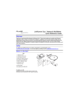
What’s in the box?
Item
4
1
1. LinkRunner Pro
2. LinkRunner Connect CD
5
3. Quick Reference Guide
4. Wireview Office Locator #1
TM
3
2
5. USB-A – USB-B Mini Cable
6
6. Registration Card
7
7. Batteries (4 AA)
PN 2688136 September 2006 Rev. 2, 12/08
© 2006 - 2008 Fluke Corporation. All rights reserved. Printed in USA
All product names are trademarks of their respective companies.
Cleaning
To prevent moisture from entering the LinkRunner Pro, clean it with a moist cloth only. Do not use organic solvents,
acid, or alkali solutions.
Safety Information
The following symbols are used on the product and in this document:
j
W
)
NOT FOR CONNECTION TO PUBLIC TELEPHONE SYSTEMS
PLEASE READ MANUAL FOR SAFETY
CANADIAN STANDARDS ASSOCIATION CERTIFIED TO CANADIAN AND US STANDARDS
WWarnings
To avoid possible electric shock or personal injury, follow these guidelines:
•
Do not use this product if it is damaged. Before using the product, inspect the case. Look for cracked or
missing plastic.
•
Do not operate the product around explosive gas, vapor or dust.
•
No serviceable parts. Do not try to service.
•
If this product is used in a manner not specified by the manufacturer, the protection provided by the
product may be impaired.
WCautions
To avoid possible damage to the Network MultiMeter and to the equipment under test, follow these
guidelines.
•
Use the proper terminals and cable for all connections.
External Features - Connections, Buttons, and the LED
1. RJ-45 LAN port
1
2
2. RJ-45 MAP port (cable testing)
3. Power Button
6
Power off – press and hold
Backlight – press once briefly
4. USB port
7
5. Selection buttons
- Up/Down arrows navigate the selections and adjust values
- Left/Right arrows show additional information and choices
- Select center button to edit a selection or toggle a value
5
6. Link indicator LED
7. Kensington lock (location on back of LinkRunner Pro)
4
3
Note: To calibrate the wire map function, use a short patch cable and connect it
between the LAN (1) and MAP (2) port connectors on the top of the LinkRunner.
Press and hold the left arrow selection button and turn on the LinkRunner.
Count on LinkRunner Pro for Answers!
First connect an RJ-45 cable from the network hub or wall plate to the LinkRunner Pro LAN port. Check the following
list of questions and associated answers to see how LinkRunner Pro can help you get the job done.
Common Questions
Is this a good cable?
Where does this cable go?
Is this cable hooked up to anything?
Is this an active Ethernet port?
What speed/duplex is this device configured for?
Can I establish Gigabit link to the network?
Can I DHCP?
Can I see traffic from this connection?
Is the PC NIC OK?
Can I PING?
Do I have network connectivity?
What slot and port am I on?
Can I use it for throughput testing?
Can I connect to an 802.1X port?
TM
- use open cable testing and a Wireview Office Locator
TM
- use toner function or Wireview Office Locator
- use Home screen
- use Home screen, check for Link and frame utilization
- use Home screen, check speed/duplex
- use Home screen, check for speed
- configure LinkRunner Pro for DHCP, check for link and PING
- use Home screen
- use Home screen, check for Link
- use PING screen
- use PING (Router, DNS, DHCP and custom list)
- use LLDP, CDP, EDP
- use Reflector screen
- use Configuration screen and LinkRunner Connect application
Navigation
Home screen – Displays link, speed/duplex, length, utilization, security authentication, connection, and
wire map information.
PING screen – Displays (scrolling from left to right) a Tx/Rx summary of all devices to the right which
will include: the Router, DHCP, DNS, and each user configured IP address.
LLDP (IEEE), EDP (Extreme Networks), CDP (CISCO) screen – Displays the switch address (MAC or IP),
switch name, slot/port, VLAN ID (optional), and VOIP VLAN Reply ID (optional).
Power over Ethernet - Displays the Power over Ethernet voltage levels for each Ethernet connector
pin.
Flash Hub Port screen – Causes the LinkRunner Pro to continuously link and unlink at a selected speed.
This is useful when identifying which port LinkRunner Pro is connected to. Use LLDP/EDP/CDP test first
if your network supports it.
Reports screen – Allows you to save up to 4reports. Each report contains a summary of the Home
screen, PING screen, and LLDP, EDP, CDP screen. The reports must be viewed on the LinkRunner
Connect PC application.
Packet Reflector Screen (optional feature) – Enables packet reflector mode, which allows the
instrument to be used as a remote device for the Fluke Networks MetroScope™ Service Provider’s
network performance tests. Use the Configuration screen to set up the parameters.
Toner screen – Generates a digital tone (IntelliTone) signal
, or two different analog tone signals
(400 Hz) and
(1 KHz) to be used with Fluke Networks IntelliTone product or common analog
probes.
Configuration screen – Multiple menu functions are accessed in this screen. The configuration screen
accesses: the LinkRunner Pro version information; user preferences; enter up to 10 PING addresses;
enable options; edit or delete reports; configure and enable packet reflector mode; select a VLAN;
enable or disable 802.1X security; perform a firmware update; or exit back to the Home screen. See
the Configuration section for details.
1.
Scroll up thru the functions
2.
Scroll right within a function
3.
Scroll down thru the functions
4.
Scroll left within a function
5.
Select a function
1
4
2
5
3
Is this an active Ethernet port?
1.
Cable/Link Status:
Straight patch
5
1
2
Crossover patch
Unknown patch (Auto-MDIX
port on hub or switch)
11
Link Level (displays when low)
6
2.
Advertised speed/duplex
3.
Actual link speed/duplex
4.
Cable length from LinkRunner Pro to
cable end or device
3
4
10
7
9
8
5.
Navigation arrows. Indicates which buttons are active.
6.
Highlighted function is the active function. While a function is active, you can scroll to other functions.
Press the center button to select a new function.
7.
Activity indicator.
8.
Network Utilization. After 10% Utilization, scale changes to 100%.
9.
PoE voltage present. Wire pairs with PoE voltage show in parentheses.
10.
Scroll bar. Indicates relative position on the page.
11.
Battery indicator. Shows voltage level as low, medium, or high. The AC adapter icon
the AC adapter (part of the optional LI-ion battery pack) is being used.
will be displayed if
Home – Link Information and Wire Map functions
The Home screen displays link or wire map information depending on the
connection. If the RJ-45 Ethernet cable is connected from the RJ-45 LAN port
to your network, LinkRunner Pro will display link information which will
include link, speed/duplex, cable length to the network connection, and
network utilization.
If LinkRunner Pro detects PoE, this screen will display PoE information. Notice
the PoE label and wire pairs are displayed.
This screen is displayed if LinkRunner Pro has successfully linked, and 802.1X
has been detected and authenticated.
Good cable
Unknown cable
Split cable
Shorted cable
Open cable - If the RJ-45 Ethernet cable is not connected to the RJ-45
MAP port on the LinkRunner Pro, a WireviewTM Office Locator, or your
network, LinkRunner Pro will display cable information.
If the RJ-45 Ethernet cable is connected from the RJ-45 LAN port to the RJ-45
MAP port (or to a WireviewTM Office Locator), LinkRunner Pro will display wire
map information which includes length, open, shorts, and wire pair mapping.
Additional Home Screen Messages
LinkRunner Pro
is discovering
LinkRunner Pro is
discovering/authenticating 802.1X
Detected 802.1X, but failed to
authenticate
Detected 802.1X, but LinkRunner Pro is
not configured for 802.1X
Un-powered Device
Token Ring
Telco
Indicates that a patch cable was
not connected between the LAN
and MAP ports while trying to run
the wire map calibration function.
This calibration is performed by
pressing and holding the left
arrow selection key while turning
on the LinkRunner Pro.
Indicates that the wire map calibration
is in progress. When the calibration is
completed, the display will show the
home screen.
The PING function contains several screens that are accessed by scrolling to the right. The first PING screen displays a
Tx/Rx summary of the Router, DHCP, and DNS PING results plus any IP addresses setup in the Configuration screen. As
you scroll to the right, the PING provides details on the Router, DHCP, DNS and up to 10 additional IP addresses are
displayed as shown below.
Minimum
Average
Round trip time Maximum
of last packet
Time in milliseconds
Summary
The 10 additional IP addresses are entered in the Configuration screen, or by using the LinkRunner Connect PC
application and transferring them via a provided USB cable to the LinkRunner Pro.
Note: If configured for DHCP, and the DHCP server cannot be found, PING will display
Duplicate IP addresses found is shown as follows:
See the configuration
for procedures to set up PING IP addresses.
LLDP, CDP, EDP
The LLDP, CDP, EDP function displays the switch address (MAC for LLDP, IP
for CDP, MAC for EDP), switch name, slot/port information (if available), and
VLAN information (also if available). The first switch discovered is displayed
first. Up to 5 switches can be displayed and are accessed by scrolling to the
right. If none can be discovered, use Flash Hub Port to discover the switch
slot/port information.
Flash Hub Port
The Flash Hub Port function will negotiate link and then unlink at a selected
speed allowing you to locate a corresponding switch slot/port by its flashing
LED. The slide bar determines the speed. To the right is faster (rabbit); to the
left is slower (turtle).
.
IntelliTone
This function can be paired up with the Fluke Networks IntelliToneTM Probe. It
allows you to use LinkRunner Pro as the tone generation device along with the
IntelliTone Probe to trace connections using either a digital tone (Fluke
TM
Networks IntelliTone ), or two different analog tones.
Digital
Tone
Reflector Mode (optional feature)
Enables packet reflector mode, which allows the instrument to be used as a
remote device for the Fluke Networks MetroScope™ Service Provider’s network
performance tests. Use the Configuration screen to set up the parameters.
Saving Reports
Allows you to save the report summary information which contains the current
Home screen, PING screen, and LLDP, EDP, CDP screen. Saved reports must be
viewed on a PC using the LinkRunner Connect PC application. Make sure
LinkRunner Pro is connected to a PC using the provided USB cable.
To save a report: Highlight the Report symbol and press the selection button.
Use the left/right arrow keys to select which report number/name to save the
summary information to (default names are Report01 – Report04; which can be
edited), and press the selection button again.
report empty
report saved
Analog
400 Hz
Tone
Analog
1 kHz
Tone
Configuration
The Configuration screen accesses multiple functions: It will display LinkRunner Pro version information, MAC
address, along with the serial number. It allows you to enable 802.1X security; change the cable length
measurements from feet to meters, set the power off timeout, use DHCP or manually enter the LinkRunner Pro IP
address, enter up to 10 IP addresses to PING, and enable options.
To avoid a duplicate IP address on your network, use DHCP instead of manually entering the IP address.
LinkRunner information
Displays LinkRunner Pro’s serial number, MAC address, and software version
numbers.
User Preferences
When FDX is selected, sets the default to full duplex for non-negotiating ports;
Select “.1X” to enable 802.1X security. This allows the unit to link to an 802.1X
secure switch; Select the cable length units as either feet or meters; Set the
power off timeout to either 10 minutes or infinity. Use the right arrow key to
toggle units and the center button to save. You can configure 802.1X security
settings using the LinkRunner Connect PC application. The unit will not power
off in PING, switch discovery, IntelliTone, or reflect modes, or when the AC
adapter is connected.
Note: LinkRunner Pro supports the following encryption key sizes: 512, 768,
and 1024 bits.
LinkRunner IP address
Allows user to configure DHCP or use manual IP, Mask, and Router addresses.
To manually enter the IP address, uncheck DHCP using the left/right arrow keys
to check and uncheck the check box. Then, using the down arrow key, move
down to the IP address. Press the selection button (center). Move right to each
digit (by using the right arrow key) and use the up/down arrow keys to select
each digit value. Keep doing this until the IP address is entered. Press the center
button to save the information. Use the same procedure as above to edit the
Mask and Router information.
Enable VLAN and enter its ID and priority. DHCP, Ping and ARP packets will then
be tagged with this VLAN ID. Uncheck VLAN when connecting to non-VLAN
networks.
PING IP address entry
Allows you to enter up to 10 PING IP addresses. When you enter the PING
screen, each address will get pinged. You may also use the LinkRunner Connect
PC application to enter the IP addresses, then using the supplied USB cable,
transfer the IP addresses to LinkRunner Pro.
Selecting the IP number/name to edit: When
is highlighted, press the
selection button (center). Use the up/down arrow keys to choose the IP number
and the selection button to select it. Notice at the bottom of the display, the IP
name changes as you scroll thru the 10 IP numbers. By default the names are IP1
– IP10.
Editing the IP address to PING: Then, using the down arrow key, move down to
the IP address. Press the selection button (center). To enter an IP address, move
right to each digit (by using the right arrow key) and use the up/down arrow
keys to select each digit value. Keep doing this until the IP address is entered,
then press the selection button to save.
Editing the IP name: Press the down arrow key to move the cursor to the IP
name field. Press the selection button (center). To enter an IP name, move right
to each character (by using the right arrow key) and use the up/down arrow
keys to select each character. Keep doing this until the IP name is entered and
then press the selection button.
To exit out of the PING IP address configuration, press the left arrow key.
Option Key entry
Allows you to enable options by entering the purchased key code. 802.1X and
Reports are included by default. Reflector is a purchased option.
To enable an option: Press the selection button to get into the options menu.
Press the selection button and use the up/down arrow keys to choose the key
digit. Use the right arrow key to move to each key digit. Press the selection
button to enter the key code. Then press the left arrow key to exit. A
successfully enabled option will be indicated by a check mark. You can also use
the LinkRunner Connect PC application to enable options.
Reports Edit/Erase
Allows you to edit report names and erase reports. Each report contains a
summary of the Home screen, PING screen, and LLDP, EDP, CDP screen. The
reports must be viewed on the LinkRunner Connect PC application.
Selecting the report name/number to edit: When
is highlighted, press the
selection button (center). Use the up/down arrow keys to choose the report
number and the selection button to select it. Notice at the bottom of the
display, the report name changes as you scroll thru the report numbers. By
default the names are Report01 – Report04.
Editing the report name: Using the down arrow key, move down to the report
name. Press the selection button (center). To edit the report name, move right
to each character (by using the right arrow key) and use the up/down arrow
keys to select each character value. Keep doing this until the report name is
entered, then press the selection button.
Erasing a report: Using the down arrow key, move down to erase the report.
Press the selection button (center) and the report is erased. Erased or empty
reports have no lines in the symbol.
Reflector Mode configuration (optional feature)
and then use the up or down arrow key to
Highlight the packet type
select the packet type that the reflector will respond to:
- any packet
- destination MAC is this LinkRunner Pro and the data string
contains a special Fluke Networks byte string (generated by the Fluke
Networks instrument)
- the data string contains a special Fluke Networks byte string
- destination MAC is this LinkRunner Pro
- any non-broadcast packet
and then use the up or down arrow key to select
Highlight the swap icon
whether the source and destination addresses are swapped in the outgoing
packet:
- swaps the source/destination MAC and IP addresses
- swaps the source/destination MAC address only
Blank - no swap; packet is sent out as it was received
The factory default conditions for your LinkRunner Pro are:
Match – FLUKE and Swap - MAC and IP
You can also use the LinkRunner Connect PC application to configure the
Reflector.
Firmware update
Allows you to download the latest LinkRunner Pro firmware through the
LinkRunner Connect PC application. Firmware updates can be downloaded
from www.flukenetworks.com/linkrunnerpro. Navigate to the LinkRunner Pro
product page and follow the links for downloads and updates.
Press the right arrow to update. Use the LinkRunner Connect PC application to
download the update files.
Exits out of Configuration menu and back to the Home screen.
Other Features
Restore Factory Defaults: Press the left and right arrow keys while powering up the unit.
Accessories
Buy LinkRunner Pro accessories, options, or other network test products by contacting a Fluke Networks
representative or send e-mail to: [email protected]. For more information go to
www.flukenetworks.com/linkrunnerpro.
Accessories
Part No.
IntelliTone Pro Toner Probe (receiver)
MT-8200-63A
WireviewTM Office Locator (ID #1)
WIREVIEW 1
WireviewTM Office Locator (IDs # 2-6)
WIREVIEW 2-6
Clip Set
CLIP-SET
RJ-45 Coupler
CIQ-RJA
Lithium ion battery pack and AC adapter
LRPRO-LION
Contacting Fluke Networks Sales, Service, and Support Centers
To order accessories or get the location of the nearest Fluke Networks distributor or service center, visit the Fluke
Networks contact website at www.flukenetworks.com/contact. Send email to [email protected]. For
operator assistance in the USA, call 1-800-28-FLUKE (1-800-283-5853). You can also visit the Fluke Networks
Knowledge Base at http://kb.flukenetworks.com.
Agency Certification and Approval
)
;
Canadian Standards Association certified to Canadian and US standards
Meets C-Tick EMC standard, N10140, complies with FCC Part 15 Class A
N10140
P
Conforms to European Union Directives Pollution Degree 2
General Specifications
Media Access
Cable Tests
Tone Generator
10BASE-T, 100BASE-TX, 1000BASE-T (IEEE 802.3), and PoE (IEEE 802.3af)
TM
Pair lengths, opens, shorts, splits, crossed, straight through, Wireview cable ID
IntelliTone digital tone: [500 KHz]
Analog tones: [400Hz, 1KHz]
UI Interface
UI Control / Data Entry
Power Button
B&W, 2”x 1” display, Link LED
Five push-buttons for selection of icons and navigation of menus
On/Off
Ports
Application Port
(2) RJ45s: network test port, loop-back wire map port
Mini-USB
Battery
4 AA batteries 4 AA batteries or optional Lithium Ion battery pack with 15VDC
1.2A AC adaptor accessory
Kensington Lock
One year
Physical Security
Warranty
Mechanical Electrical Specifications
Weight
Dimensions
RJ-45 Network Port
10 oz. with 4 AA Alkaline batteries
8.4 oz. with 4 AA LI batteries
5.3” height x 3.1” width x 1.3” depth
13.3cm height x 8cm width x 3.2cm depth
Designed to withstand a maximum of 100V
Security
Operational Security
IEEE 802.1X option for network authentication
Environment Specifications
Operating Temperature
Storage Temperature
Operating Humidity
Vibration Requirements
Connection To Public Telephone
Network
10 – 40 degrees C
-20 to 60 degrees C
95% relative humidity (non-condensing)
Meets requirements for MIL-PRF-28800F for Class 2 random
vibration
Should never be connected to the public telephone network