1
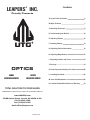
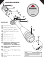
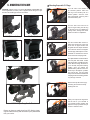
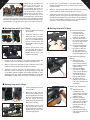
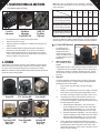
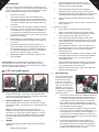
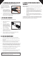
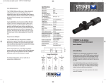
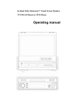
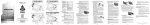
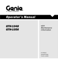
1
LEAPERS , INC.
®
OPTICS
Complete Installation and
Operating Instructions
W W W. L E A P E R S . C O M
LEAPERS INC.
Index
®
Proudly Presents
UTG
OPTICS
RANGE
ESTIMATING SCOPES
RETICLE
INTENSIFIED SCOPES
TOTAL SOLUTION TO YOUR NEEDS
-COMMITMENT TO BEST QUALITY, BEST VALUE AND BEST SERVICE-
www.LEAPERS.com
32700 Capitol Street, Livonia, MI 48150, U.S.A.
Tel:(734)542-1500
Fax:(734)542-7095
Email:[email protected]
MUO008011205
A. Scope Parts Illustration 4
B. Major Features 7
C. Mounting the Scope 8
D. Understanding the Reticle 12
E. Adjusting Diopter 14
F. Installing Battery 14
G. Adjusting Reticle Illumination 14
H. Adjusting Magnification 15
I. Adjusting Parallax and Focus 16
J. Zeroing
16
K. Removing and Installing Lens Caps 22
L. Installing Sunshade 22
M. Care and Maintenance 22
N. Limited Lifetime Manufacturer’s Warranty 23
4
5
a. scope parts illustration
11
!
01
WARNING:
02
Read entire manual before
mounting your scope.
Make sure the firearm
is not loaded upon
installation.
G
R
03
04
05
06
07
08
PARTS LIST
01. Eyepiece Assembly
09
02. EZ-TAP Control Panel (For Reticle
Illuminated Scopes with IE Capability)
10
03. Power Ring (For Variable Power Scopes
Only)
04. Windage Adjustment Knob
05. Elevation Adjustment Knob
12
06. Adjustment Hex Screw (Optional)
07. Zero Locking Ring (Optional)
08. Reticle Illumination Adjustment (For Reticle
Intensified Models Only) or Parallax
Adjustment Ring (For Side AO Models Only)
09. Objective Parallax Adjustment Ring (For Front
AO Models Only)
10. Objective Lens Protective Ring ( Optional,
Needs to Remove in Order to Install
Sunshade)
11. Ocular Lens
12. Integral Sunshade (For Models with Angled
Objective)
Note:
Scope diagram is for illustration purposes only,
not intended to represent your actual product
appearance.
6
b. Major Features
ACCESSORIES
►►
Allen Wrench
(Optional)
Optional - 3” Sunshade
(for 50mm Obj. Dia. Scope)
Optional - 2.5” Sunshade
(for 40mm Obj. Dia. Scope)
Optional - 2” Sunshade
(for 32mm Obj. Dia. Scope)
Flip-open Lens Caps
(Appearance may vary.)
Battery
(For Reticle Intensified
Models Only)
►►
Cleaning Cloth
►►
UTG
7
Built on True Strength Platform, Completely Sealed
and Nitrogen Filled, Shockproof, Fogproof and
Rainproof
•
Rugged one piece tube construction for all terrains/
weather.
•
Smart spherical structure (SSS) to achieve the most
responsive, precise and reliable windage and elevation
adjustment.
•
Precision machined to exact tolerances from aircraft-grade
aluminum alloy to achieve the desired performance under
most heavy recoil.
•
Completely sealed and nitrogen filled to eliminate risk of
water ingress and fogging.
•
Positive and precise click value for accurate and consistent
shooting.
•
Most disciplined quality control and extensive shock and
vibration testing to guarantee optimal recoil resistance
capability and consistent performance.
Multi Layer Lens Coating for Optimum Light
Transmission
•
Unique high tech coatings applied to lens elements ensure
best light transmission for optimal optical performance.
•
Multi layer coatings ensure maximum utilization of all
ambient light for the best resolution and clarity.
Target Turrets with Unique Zero Locking and Zero
Resetting Features
(For Target Turret Models Only)
►►
►►
•
Most innovative design for user friendly W/E control.
•
Easy and repeatable Zero Locking and Zero Resetting
provides the most needed protection and convenience.
Wide Field of View and Tactical Mil-Dot Reticle (For
Range Estimating Models Only)
•
Wide field of view and edge to edge lens clarity makes it
easy to pick up quarry on the peripheral edge of the sight
image.
•
The precise tactical Mil-Dot reticle allows the shooter to
estimate ranges for most optimal aiming and shooting
performance.
High Quality Precision Machined Parts
•
►►
Illuminated Reticle with Red/Green Dual or 36-color
IE Illumination(For Reticle Intensified Models Only)
•
Mounting Rings
(Optional. Appearance may vary.)
Precision machined parts guarantees smooth and
accurate operations and delivers consistent and reliable
performance.
Adjustable color and intensity of the illuminated reticle
gives optimum reticle clarity in variable light conditions,
increasing accuracy in daylight and twilight environments.
8
9
c. Mounting the Scope
CAUTION: Always ensure your rifle is UNLOADED, UNCOCKED and,
where applicable, the safety catch is applied before fitting the scope.
Practice safe handling procedures at all times.
C-1. QD Lever Lock
C-3. Thumb Nut Lock
Mounting Scope with C-1 Rings
1
Turn the Cam Lever leftward to
its unlocked position. Place the
QD ring on the Picatinny rail at a
desired position. Seat the cross
bolt at the bottom of the ring into a
selected Picatinny slot.
2
Turn the Cam Lever from left to
right to begin locking the QD ring
on the rail, but do not complete the
locking motion, leaving some travel
distance to allow for adjustment.
3
Use the included Allen wrench to
adjust the Hex Screw at the side
of the cam for proper tension and
fit against the rail. Adjust clockwise
to increase the tension and tighten
the clamping width. Adjust counterclockwise to decrease the tension
and increase the clamping width.
4
The optimal tension is achieved when
the side plate first makes contact
with the Picatinny rail while the Cam
Lever still has enough travel left for
you to securely snap into its locking
position. Once you achieve the
optimal tension, push the Cam Lever
all the way to the right for a positive
lock onto the rail. You may repeat
Step 3 and 4 if needed to find the best
clamping tension and locking position
for your rings on the rail.
5
Remove the top half of the ring by
loosening the screws and slowly
backing them out.
6
Place your scope on the ring bases.
Put the rifle to your shoulder in
your natural shooting position and
adjust the scope eye relief until you
achieve a full field of view.
C-2. Twist Lock
C-4. Hex Screw Lock
C-5. Flat Top or Carry Handle Mount
Ensure you have top quality rings from UTG. Buying cheap
rings is a false economy and can result in poor performance
from your combo.
10
Replace the top ring halves and
tighten the screws evenly by
1 5
3 7
the Cross-torque Pattern. Do
not over-tighten the screws as
damage to scope tube may occur.
2
4
6
It is recommended to grasp the
8
Allen wrench by its short end to
perform final tightening of the
screws with torque value at about
15 inch-lb. Using the long end of the Allen wrench to tighten ring screws
will result in over-tightening and may cause permanent damage to rings
and deformation of scope tube. The scope is now ready to be zeroed.
7
Mounting Scope with C-2 or C-3 Rings
Locking Holes
1.
Fit the ring bases to the mount
rail of the rifle.
2.
Tighten the Twist Lock or the
Thumb Nut with your finger.
To ensure a firm grip, plug the
long end of the Allen Wrench
into the Locking Holes and
further tighten it by turning the
short end.
3.
Remove the top piece of the
ring and place the scope on
the exposed fitted ring bases.
Replace the top piece of the
ring and finger tighten.
4.
Put the rifle to your shoulder in your natural shooting position and
adjust the scope eye relief until you achieve a full field of view.
5.
When you have found the ideal eye relief, rotate the scope so the
reticle crosshair is vertical and perpendicular to the rifle.
6.
Tighten the screws on the rings to by following Step 7 of C-1 ring
instruction. Ensure a firm grip on the scope.Using the long end
of the Allen wrench to tighten ring screws will result in overtightening and may cause permanent damage to rings and
deformation of scope tube. The scope is now ready to be zeroed.
Mounting Scope with C-4 Rings
1.
Fit the ring bases to the mount
rail of the rifle.
2.
Make sure the Stop Pin fully
sink into the position hole on
the rail if applicable. Insert the
short end of the Allen Wrench
into the screws and fully
tighten by turning the long end
and ensure a firm grip.
3.
Remove the top piece of the
ring and place the scope on
the exposed fitted ring bases.
Replace the top piece of the
ring and finger tightens.
Stop Pin
11
4.
Put the rifle to your shoulder in your natural shooting
position and adjust the scope eye relief until you achieve
a full field of view.
5.
When you have found the ideal eye relief, rotate the scope so the
reticle crosshair is vertical and perpendicular to the rifle.
6.
Tighten the screws on the ring to by following Step 7 of C-1 ring
instruction. Ensure a firm grip on the scope.Using the long end of
the Allen wrench to tighten ring screws will result in over-tightening
and may cause permanent damage to rings and deformation of
scope tube. The scope is now ready to be zeroed.
Mounting Scope with C-5 Mount
1. Firearm with Carry Handle:
1) Place the integral
mounting deck of the
scope into the carry
handle of your firearm.
2) Align one of the holes on
the mounting deck with the
hole on the carry handle
for best eye relief.
3) Insert the knurled thumb
nut with the integral bolt
through the O-ring and
the hole selected from
the underside of the carry
handle and tighten the nut.
2. Rifle with Picatinny/Weaver
Flat Top:
1) Attach the integral
mounting deck of the
scope onto the Picatinny
Flat Top Adaptor with the
supplied screws.
2) Place the assembled
scope/flat top adaptor
combo onto the Picatinny/
Weaver flat top rail on
your rifle and adjust for
best eye relief position.
3) Secure the combo by
tightening the two thumb
nuts on the side of the Flat
Top Adaptor.
3. Firearm with .22/Airgun Flat
Top:
1) Attach the integral
mounting deck of the
scope onto the .22/Airgun
Flat Top Adaptor with the
supplied screws.
2) Place the assembled
scope/Flat Top Adaptor
combo onto the .22/Airgun
flat top rail on your rifle
and adjust for best eye
relief position.
3) Secure the combo by
tightening the two thumb
nuts on the side of the Flat
Top Adaptor.
12
d. understanding the reticle
Mil-dot reticle is the most widely used reticle on
Leapers riflescopes which provides range estimating
capability. The reticle has a big crosshair throughout
the reticle and multiple dots spread equally apart on
the lines in the central area. The distance between
two adjacent dots is designed to be 1 milli-radian or
3.44MOA at 10X.
1. Each scope has a reticle for aiming. A reticle is a thin planar component
disposed perpendicular to the optical axis inside the main tube. It is made
by etched metal film or etched glass. The former is called Wire Reticle,
and the latter is called Etched Glass Reticle.
2. For Leapers riflescopes, the reticle is on the second image plane. The
reticle doesn’t change when the magnification is adjusted. Therefore,
the dimension that the reticle occupies on the image of the target is
dependent on the magnification.
3. Leapers offers a variety of reticles for different scopes. Below is the
introduction of the reticles.
The regular mil-dot reticle on the market usually has
4 dots on each direction. Leapers scopes usually
has 6 or 9 dots on each direction to provide more
flexibility in range estimating. For mil-dot reticle with
9 dots on each direction, if you count the 2 inner tips
of the opposite crosshairs, there are 19 aiming points
or totally 21 including the inner tips.
TARGET DOT RETICLE
Target Dot reticle consists of a single floating dot in
the center as the aiming point with the least visual
distraction. It is commonly used for quick aiming
applications with lower demand for pin-point accuracy.
The shooter aims by pointing the dot on the target. For
Leapers riflescope, the dot size is about 2MOA.
13
MIL-DOT RETICLE
►►
Range estimating
2 mils
requires common
knowledge/experience
CIRCLE DOT RETICLE
Circle Dot reticle includes a floating circle and a dot
in the center. The circle draws the eye to the target
and the dot indicates the exact aiming point. Circle
Dot reticle is ideal for shotgun shooting, fly hunting as
well as tactical applications which require quick target
acquisition.
2.5 mils
about your target’s
actual width or height.
►►
1 mil in a scope reticle is the distance from the center of one
dot to the center of the next dot.
►►
DUPLEX RETICLE
Set your scope at 10X or the proper power specified by the
mil-dot chart. Place the center of the dot against one edge of
Duplex reticle consists of thin crosshairs in the center
and four posts extending to the reticle perimeter from
the edges of the thin crosshairs. The thicker posts
stand out against the background, while the thin
crosshairs are for precise aiming and better view of
the area of interest on the target. Duplex reticle could
be etched on glass or etched from metal thin film.
Accordingly, the center crosshair may be floating or
connected to the outer bars.
the target and measure to the opposite edge of the target.
►►
scope model, a formula is available to estimate the distance of
the target. An example formula for 4-16X40 Full Size Scope is
provided here for your reference:
Height or Width of Target in Meters x 1000
PRO 5-STEP RETICLE
Pro 5-step reticle is designed for crossbows, but
can also be used in other applications such as rifles,
airguns, etc. The reticle consists of five horizontal lines
and a vertical line. And there is a thin crosshair in the
center. If used on crossbows, the horizontal lines are
for aiming at 10, 20, 30, 40 and 50-yard distances. The
lines are calibrated for 300fps crossbows. The user
needs to find out the exact yardage of each line during
zeroing process.
Once the target has been measured in mils, depending on the
Height or Width of Target in Mils.
= Range in Meters (1M = 1.0936 Yards)
►►
For accurate range estimating the size of the target must be
known.
►►
Each model comes with its own formula and a pre-calculated
mil-dot table of most used distance estimates to aid the user.
Example:
Zeroing the Pro 5-Step Reticle Scope:
If used on a rifle or an airgun, zero a scope with Pro 5-step Reticle as
you would with a regular scope (please refer to the Zeroing section).
If used on a crossbow, follow the steps below to zero a scope with Pro
5-step Reticle:
1. Place a target 10 yards away, aim at the center of the target with the
center crosshair and fire a few test shots.
2. Adjust the windage and elevation until you hit the bullseye (please
refer to Zeroing section for W/E adjustment).
3. Place the target 20 yards away, still aim with the center crosshair and
shoot. Make minor adjustment to windage and elevation if needed.
4. Walk back 8-10 yards and fire shots at the center of the target to
determine the accurate yardage of the next descending crosshair
line. Repeat this for each of the 4 descending crosshair lines.
8 MIL
Total Number of Dots Occupied: 8
Target Category: Prairie Wolf
Estimated Size of the Target: 0.8 meter
Width of Target in Meters x 1000
Width of Target in Mils.
0.8 meter x 1000
8
= Range in
Meters
= 100 Meters
14
Diopter adjustment provides additional focus adjustment to adapt the
scope to your eyesight.
1.
G
e. adjusting diopter (Eye Piece Adjustment)
G OR R
G
Diopter adjustment ring is located
at the ocular end of the scope.
Aim the scope at your target,
hold still and turn the dial ring
clockwise or counter-clockwise
until both the crosshair and the
target are in the sharpest focus.
R
R
G OR R
G
Note: Different individuals will have
different eye focus which will result in different diopter setting. A person
will use different diopter settings with or without eye glasses.
R
G AND R
F. installing battery
G
R
(For Reticle Intensified Models Only)
G OR R
Turn On/Off
1. Press either the G or R button to turn on
the light.
2. Press and hold either the G or R button
for 1 second to turn off the light.
3. Light will go off after 1 hour with no action.
Operating in the RGB Mode
1. Press the R button to turn the red light on or
to change brightness of the red light.
2. Press the G button to turn the green light on
or to change brightness of the green light.
Switching between RGB and Multi-Color
Modes for IE Models
1. Press BOTH G & R buttons at the same time
for less than 1 second.
Operating in Multi-Color Mode for IE Models
1. Press the R button to change the color along
the color axis in the Color Index Table.
2. Press the G button to change the color along
the intensity axis in the Color Index Table.
IE
F-1. EZ-TAP
F-2. Side Rheostat
36 COLORS
G Button
R Button
FULL
1. The battery is housed inside the EZ-TAP Battery housing or the side
wheel Red/Green Illumination Rheostat.
3. Use your other hand to open the battery compartment by unscrewing
the top cap.
4. Verify the battery included with your scope. It is either CR2032 OR
CR1620. Remove the old battery(if there is one) and install a new
one of the same type. Make sure the positive (+) side is facing up.
5. Replace the cap and screw it clockwise to tighten.
g. adjusting Reticle Illumination
(For Reticle Intensified Models Only)
G-1.
Standard Rheostat
G-2.
Compact Rheostat
Color
2. Firmly hold the housing or the Rheostat with 2 fingers.
15
Color Index Table
Intensity
Magenta
Thistle
Plum
Violet
Orchid
Purple
Pink
Rosy
Brown
Coral
Crimson
Brown
Maroon
Golden
Chocolate
Rod
Yellow
Khaki
Orange
Law
Ngreen
Plae
green
Spring
Green
Olive
Drab
Sea
Green
Forest
Green
Cyan
Azure
Turquoise
Cadet
Blue
Dark
Cyan
Teal
Skyblue
Dodger
Blue
Indigo
Midnight
Blue
Navy
Blue
Olive
H. Adjusting Magnification
(For Variable Power Scopes Only)
1. For variable power scopes, there
is a power ring in front of the
eyepiece assembly. To change
magnification, turn the ring to align
the desired number on the ring with
the index dot on the main tube.
G-3.
EZ-TAP® Console
G-1 and G-2 Illumination Adjustment
Dial the Rheostat to turn on the illumination and verify its color and
brightness at each position.
G-3 Illumination Adjustment (RGB Models or IE® Models)
Memory Feature
When turned on, G-3 illuminated reticle shows the same color and
brightness you last used.
2. The lower power provides wider
field of view for quick aiming at
close range. The higher power
is for precise long-range aiming.
When the numbers on the ring
is not visible under low light
condition, turn the ring left to
increase the power, or turn the ring
right to decrease the power.
3. Note: Never loosen the screw in the
power ring. Doing so will break the
sealing of the scope and destroy
the fogproof feature. The power
ring should not be disassembled.
Do not try to lubricate it.
Any such action will void the
warranty.
H-1. Adjusting Power Ring
H-2. Power Ring Screw
16
i. adjusting Parallax and Focus
(For Models with AO Only)
25
yds
35
yds
50
yds
100
yds
200
yds
1/8
7/40
1/4
1/2
1
Inches of Movement per Click in
1/16
Windage/Elevation Models with
1/4 in. Per Click @ 100 Yards
7/80
1/8
1/4
1/2
Inches of Movement per Click in
1/32
Windage/Elevation Models with
1/8 in. Per Click @ 100 Yards
7/160
1/16
1/8
1/4
Inches of Movement per Click in
Windage/Elevation Models with
1/2 in. Per Click @ 100 Yards
I-1.
Front AO
Adjustment
I-2.
Side Wheel
Adjustable
Turret(SWAT) AO
I-3.
SWAT AO
Big Wheel
(Optional)
1.
Find the proper type of dial from the images above.
2.
Aim the scope at your target.
3.
Adjust the eyepiece until both the crosshair and the target are in
sharpest focus.
4.
Dial the Parallax Adjustment Ring, Side Wheel or Big Wheel,
depending on what is available on your model, to the desired
distance setting until the target is in the sharpest focus and the
center of the crosshair stays on the target while you examine the
image by slightly moving your head.
J. Zeroing
17
Note: Each click of adjustment for the windage or elevation
knob moves the impact point by the amount shown in the table
on the next page:
Note: Since climatic conditions such as altitude, temperature, wind
and rain can affect the pellets or bullets trajectory, you may experience
some deviation in the exact settings during different shooting sessions.
J-1 Sniper W/E Operation
1.
The Windage and
Elevation Adjustment
Target Knobs have a
unique Resetting Screw
design. An Allen wrench is
provided with the scope for
adjustment.
2.
ZERO LOCKING (W/E
are “ locked” for a new
scope.)
The purpose of zeroing the scope is to ensure that the scope is aligned
with the impact point of the pellet or bullet from the rifle. Before zeroing
the scope, read the following adjustment knob instructions carefully.
Zero Resetting
Hex Screw
Zero
Locking
Ring
Finger tighten the Zero Locking Ring by rotating clockwise by 40
- 70 degrees. Do not over-tighten. When the Zero Locking Ring is
tightened, the windage or elevation adjustment knob is “locked”.
The knob will not rotate, preventing any accidental movement to
lose zero.
Note: For crossbow scopes with PRO 5-STEP Reticle, please also refer to
section D for more zeroing details.
3.
ZEROING
Un-lock the adjustment knobs by turning the Zero Locking Ring
counter clockwise by 40 - 70 degrees. Now, Windage/Elevation
adjustment knobs can be rotated.
J-1.
Sniper W/E
J-2.
TF2+ Tool-free W/E
J-3.
Coin-dial W/E
i.
Place a target 100 yards away. (35 yards for airgun
scopes)
ii.
Ideally, use a steadying device such as a bipod or shooting
stand, set the scope at the highest magnification, aim at
the center of the target and fire a test shot, if safe to do so.
iii.
If the impact point of the pellet or bullet is exactly in the
center of the target then the scope is zeroed. If it is not,
you will need to adjust the reticle using the elevation and/or
windage adjusters as follows:
a. Vertical Adjustment (Elevation) - Use your fingers to
turn the adjusting knob as required. One click in either
direction equals approximately 1/2, 1/4 or 1/8 inch at
100 yards (check exact specifications for your scope).
J-4.
True Hunter W/E
(Turret Color
May Vary)
J-5.
Finger Adjustable
W/E
J-6.
Lockable W/E
(Turret Color
May Vary)
b. Horizontal Adjustment (Windage) - Use your fingers to
rotate the adjusting knob as required. One click in either
direction equals approximately 1/2, 1/4 or 1/8 inch at
100 yards (check exact specifications for your scope).
iv.
Having adjusted the windage and elevation as required,
fire, if safe to do so, another test shot. Keep adjusting and
test firing until the test shot impacts on the center of the
target when the reticle is on the center of the target. This is
vital for accurate shooting.
18
4.
ZERO RESETTING
Once your scope is zeroed, rotate the Zero Locking Ring to lock
Zero. The “0” marking may not be facing you at the original center
position now. Optionally, you can use the following steps to Reset
Zero by rotating the “0” marking to the center positions:
i.
Ensure zero is “locked”.
ii.
Use the Allen wrench to turn the Zero Resetting Hex
Screw by 180-360 degrees to dis-engage the W/E knobs.
(IMPORTANT: Be gentle with the screw movement. Do not
over extend the rotation. Stop when meeting resistance in
the rotation)
iii.
When the W/E knob is dis-engaged, rotating the knob will
not produce any clicking sound and will not affect zero. You
can re-position the “0” marking to the center position. (If
you get clicks when rotating the W/E knob, the knob was
not properly dis-engaged. You need to go back and re-start
from zeroing your scope.)
iv.
Before tightening the Zero Resetting Hex Screw, turn the
Zero Locking Ring counter-clockwise by 40-70 degrees to
un-lock zero.
v.
Be careful to keep the W/E knob still now that it is unlocked. Use the Allen wrench to gently tighten down the
Zero Resetting Hex Screw to complete Zero Resetting. (If
you get clicks while tightening the screw, you will need to
go back and re-start from zeroing you scope.)
vi.
IMPORTANT: Rotate the Locking Ring clockwise to lock
zero immediately.
Follow the instructions that came with your bore
sighter and install it in the muzzle of your rifle lining it
up with the scope as close as possible.
b.
Pull the windage/elevation knob out for adjustment.
c.
Sighting through the scope as though you were going to
shoot and dial the knobs to make adjustment for the windage
or elevation until the crosshair matches the bore sighter.
d.
Push the windage or elevation knob down to lock the zero
position.
e.
Remove the bore sighter from the muzzle. You are ready for
zeroing the target.
ii. Zeroing on the Target
Important Note: When turning the Zero Resetting Screw loose to
dis-engage W/E, zero has to be “locked”. When tightening the Zero
Resetting Screw to engage W/E, zero cannot be locked. Scope damage
may occur if the steps are not followed.
a.
Place a target 100 yards away (35 yards for air gun).
b.
Ideally, use a steadying device such as a shooting stand
or bipod, set the scope at highest magnification, aim at the
center of the target, fire a test shot, if safe to do so.
c.
If the impact point of the pellet or bullet is exactly in the
center of the target then the scope is zeroed. If not, you will
need to adjust the reticle using the elevation and/or windage
adjustment as follows:
d.
Vertical adjustment (Elevation) – Use your fingers to turn
the adjusting knob as required. One click in either direction
equals approximately 1/2, 1/4 or 1/8 inch at 100 yards
depending the model.
e.
Horizontal adjustment (Windage) - Use your fingers to rotate
the adjusting knob as required. One click in either direction
equals approximately 1/2, 1/4 or 1/8 inch at 100 yards
depending the model.
f.
Having adjusted the windage and elevation as required, fire,
if safe to do so, another test shot. Keep adjusting and test
firing until the test shot hit the target center.
g.
Now the scope should be zeroed. Make sure to lock both
elevation and windage knobs.
J-2 TF2+ Tool Free W/E Operation
Pull up To Unlock
Adjustment Stage
Lock Down Stage
Push Down To Lock
1.
2.
The Windage and Elevation Adjustment Knobs have a unique
2-stage Tool-free design. A new scope comes with both knobs
secured down in the zero-locking mode. Pulling the knobs upward
allows for windage/elevation adjustment.
4.
ZERO RESETTING
Once your scope is zeroed,
push down both knobs and
make sure they are fully
locked. The “0” marking
may not be facing you at the
original center position now.
Optionally, you can use the
following steps to Reset Zero
by rotating the “0” marking to
the center positions:
i.
Use the Allen wrench provided to turn both Zero Resetting
Hex Screws on the side of the knob counterclockwise for
1 to 2 turns to dis-engage the W/E knobs. When a knob
is “dis-engaged”, the top cap of the knob can freely spin
without reticle movement. (IMPORTANT: Be gentle with
the screw movement. Do not over extend the rotation. Stop
when the W/E knob is dis-engaged)
NOTE: To lock an adjustment knob requires proper gear
engagement internally. Before pressing the knob down to lock,
use minor force to push to get the feel of resistance. If tough to
push down, make very slight rotational adjustment (no clicking)
to locate the right position to press down. DO NOT force the
lock-down.
ii.
When the W/E knob is dis-engaged, rotating the knob will
not produce any clicking sound and will not affect zero. You
can re-position the “0” marking to the center position. (If
you get clicks when rotating the W/E knob, the knob was
not properly dis-engaged. You need to go back and re-start
from zeroing your scope.)
ZEROING
iii.
Be careful to keep the W/E knob still now that it is unlocked. Use the Allen wrench to gently tighten down the
Zero Resetting Hex Screw to complete Zero Resetting. (If
you get clicks while tightening the screw, you will need to
go back and re-start from zeroing you scope.)
ZERO LOCKING (W/E are “ locked” for a new scope.)
When the adjustment knob is pushed down, the knob is “locked”
and cannot be rotated. This will prevent any accidental movement
to lose zero.
3.
19
a.
Pull up the windage and elevation adjustment knobs to allow for
adjustment.
i.
Zeroing with a Bore Sighter
20
J-3, J-4, J-5 W/E Operation
WINDAGE/ELEVATION DIALING INSTRUCTION
J-3
Use a flat head
screwdriver
to adjust the
windage and
elevation.
1.
J-4
Apply gentle force
on the rim and
dial the knob.
J-5
Apply gentle force
on the plastic tab
and dial the knob.
A.
Lock both screws down, making sure that they are flush
with the surface.
B.
Apply a little loctite or similar adhesive on the flat surface
of the knob. Make sure that no adhesive gets into the
screw holes or onto the screws.
C.
Carefully place the face cover back on the knob and align
with the locking holes properly. Firmly press the face
cover to achieve full contact and wait a few seconds to let
the cover adhere to the flat surface of the knob.
2. ZERO LOCKING (W/E are “
locked” for a new scope.)
i.
Unscrew and remove the cap
of the adjustment knob. Put
the cap away in a safe place.
Gently dial the knob and test if
it is locked. If not, you can skip
section ii.
ii.
To Unlock: Locate the two
locking screws as shown on
the right. Use the included small Allen wrench to unlock both
locking screws by turning them counterclockwise 1/4 revolution.
iii.
To Lock: Use the included small Allen wrench to fully lock down
both screws by turning them clockwise. It is recommended that
you gradually lock both screws alternately until they are fully
and evenly locked.
ii.
iii.
Zeroing with a Bore Sighter
a.
When the turret is ready for adjustment, you will
able to dial and have a clear audible click.
b.
Follow the instruction of your bore sighter and
install it in the muzzle of your rifle, lining it with the
scope as closely as possible.
c.
If applicable, turn on the illumination and set it at
your prefered color and brightness.
d.
Sighting through the scope as though you were
going to shoot and dial the knobs to make
adjustment for the elevation and/or windage until
the crosshair matches the bore sighter.
3. ZEROING - Unlock the adjustment knob to allow for adjustment.
i.
Zeroing on a Target
a.
Place a target 100 yards away (35 yards for air
gun).
b.
Use a steadying device such as a shooting stand
or bipod, set the illumination to your prefer settings,
aim at the center of the target and fire a test group
shot, if safe to do so.
c.
If the impact point of the test shot is exactly in the
center of the target then the scope is zeroed. If
not, you will need to adjust the reticle using the
elevation and/or windage adjustment. Follow the
Point of Impact (POI) direction on the turret to dial
the knob accordingly.
d.
Having adjusted the elevation and windage as
required, fire, if safe to do so, another test group.
Keep adjusting and test firing until the test shot hit
the target center in an acceptable small grouping.
Now the scope should be zeroed. Make sure to replace both
elevation and windage knob caps.
J-6 Lockable W/E Operation
The Windage and Elevation Adjustment Target Knobs have a
unique Locking Screw design. An Allen wrench is provided with
the scope for adjustment.
21
DO NOT over-loosen the locking screws! It may cause the
face cover to fall off if screws are backed out too far. If, by
mistake, the face lid fell off when you are looseing the screws,
please follow instructions below to replace the face cover.
ZEROING - Unscrew and remove the cap of the adjustment knob.
Put the cap away in a safe place.
i.
1.
WARNING:
ii.
Zeroing with a Bore Sighter
a.
When the turret is ready for adjustment, you will able to
dial and have a clear audible click.
b.
Follow the instruction of your bore sighter and install it in
the muzzle of your rifle, lining it with the scope as closely
as possible.
c.
If applicable, turn on the illumination and set it at your
prefered color and brightness.
d.
Sighting through the scope as though you were going
to shoot and dial the knobs to make adjustment for the
elevation and/or windage until the crosshair matches the
bore sighter.
Zeroing on a Target
a.
Place a target 100 yards away (35 yards for air gun).
b.
Use a steadying device such as a shooting stand or
bipod, set the illumination to your prefer settings, aim at
the center of the target and fire a test group shot, if safe
to do so.
c.
If the impact point of the test shot is exactly in the center
of the target then the scope is zeroed. If not, you will
need to adjust the reticle using the elevation and/or
windage adjustment. Follow the Point of Impact (POI)
direction on the turret to dial the knob accordingly.
d.
Having adjusted the elevation and windage as required,
fire, if safe to do so, another test group. Keep adjusting
and test firing until the test shot hit the target center in an
acceptable small grouping.
e.
Now the scope should be zeroed. Make sure to lock
both elevation and windage knobs and replace the knob
caps.
22
23
k. removing AND INSTALLING lens capS
(For Models with Detachable Lens Caps Only)
Lens caps are designed with
grooved inner surface to tightly
fit over the scope objective and
eyepiece.
1.
To remove, grab the lens
cap firmly and pull it off the
scope. Wiggle the cap gently
if necessary to help slide it off.
2.
To install, align grooves in the
cap with the scope surface and gradually push the cap toward
the scope until it is completely seated.
l. installing Sunshade
(For Models with Detachable Sunshade Only)
1.
Remove lens cap on the
objective lens.
2.
Unscrew the Objective
Lens Protective Ring off the
objective. (Not all models
come with this ring. Skip this
step if not applicable.)
3.
Screw on a compatible
sunshade to the front of the objective. Make sure it is
tightened and fully secured.
4.
Screw the Objective Lens Protective Ring onto the front of
Sunshade. (Skip this step if not applicable.)
m. Care and Maintenance
1.
Take care not to drop or knock the scope once it is zeroed.
2.
Keep the protective lens covers in place when the scope is not
being used.
3.
Maintain the metal surface of the scope by removing any dirt or
sand with a soft brush so as to avoid scratching the finish.
4.
Wipe the lens with a clean flannel cloth to keep it clean and dry. In
order to avoid scratching the glass, ensure both the lens and cloth
are clean. Do not use finger or finger nail to touch/clean lenses.
5.
Store the scope in a cool dry place when not in use. Be careful to
avoid contact with acid, alkaline or corrosive chemicals.
6.
Do not attempt to lubricate any part of the scope.
7.
Do not disassemble the scope. Do not loosen or remove screws
or parts. Any such or similar actions will void the warranty.
Caution: Viewing the sun can cause serious eye injury. Never look
directly into the sun with this or any scope.
n. Limited Lifetime Manufacturer’s
Warranty
Warranty against material or workmanship defects applies based on the
following conditions -
•
Scope was purchased new. Evidence of purchase is
required for warranty service.
•
Scope was not disassembled, parts / screws not removed
or loosened, and the scope was not tampered with in
any way. Any evidence of such interference will void the
warranty.
•
Scope has not been abused, maliciously damaged or
treated in a manner not in keeping with the purpose it was
designed for.
For warranty service, please contact the scope distributor and provide
a written problem description to obtain a Return Authorization Number
before returning the product for repair or replacement.
24
e
r
o
l
p
Ex
More
At
, Inc.,
Leapers
in
artered
headqu
s
h
.,
.A a
an, U.S
Michig
s
s
e
in
the bus
been in
,
g
n
ti
o
o
lying sh
of supp
r
o
o
td
u
and o
hunting
e
W
.
1
ce 199
gear sin
d
e
is
m
ompro
set un-c
r
fo
s
rd
a
nd
.COM
high sta
PERS
ss
e
in
s
u
.LEA
rb
W
u
o
f
W
o
W
all
ur goal
ons. O
operati
l
tota
vide a
is to pro
e of
n
li
y
n
n for a
solutio
ffer. We
ts we o
produc
ntion to
se atte
pay clo
s and
y trend
industr
back,
er feed
custom
g
n makin
focus o
with a
e
h
ss nic
t-in-cla
the bes
r
fo
able
ts avail
produc
n
a
ng d
, shooti
hunting
siasts
r enthu
outdoo
.
like you
www.LEAPERS.com
32700 Capitol Street, Livonia, MI
48150, U.S.A.
Tel:(734)542-1500
Fax:(734)542-7095
Email:[email protected]