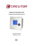
1
ELECTRICITY POWER SUPPLY
QUALITY ANALYZER
QNA-413
(Code Q20411 / Q20413)
USER MANUAL
( M98155601-03-06C )
(c) CIRCUTOR
S.A.
QNA-413 CONTENTS
1.-
2.-
3.4.5.-
6.7.-
8.-
9.10.11.12.-
page no.
BASIC INSTRUCTIONS .............................................................................. 3
1.1.- Checking the contents of your package. ..................................................... 3
1.2.- QNA-413Models ......................................................................................... 3
1.3.- Safety warnings .......................................................................................... 4
1.4.- Operating instructions ................................................................................. 4
MAIN FEATURES ....................................................................................... 4
2.1.- Basic features ............................................................................................. 5
2.2.- Electrical features ....................................................................................... 6
ANALYSIS MODES ..................................................................................... 7
DATA STORAGE IN MEMORY (automatic mode) ...................................... 7
INSTALLATION & START-UP..................................................................... 8
5.1.- Connection terminal .................................................................................... 9
5.1.1.- Communications cables for RJ connectors .................................... 10
5.2.- Starting the QNA-413 analyzer ................................................................. 11
5.3.- Connection diagram for the QNA-413 ....................................................... 12
5.3.1.- 4 wire three-phase power systems ................................................. 12
5.3.1.1.- Direct connection ................................................................. 12
5.3.1.2.- Via voltage transformers ...................................................... 13
5.3.2.- 3 wire three-phase power systems ................................................. 14
5.3.2.1.- Voltage transformers (installation recommended for MV) .... 14
5.3.2.2.- Direct connection ................................................................. 15
5.3.2.3.- Via voltage transformers ...................................................... 16
THE QNA-413 ANALYZER'S INTERNAL BATTERY ................................ 17
OPERATING MODE ................................................................................. 17
7.1.- Display and buttons .................................................................................. 17
7.2.- Turning the analyzer on ............................................................................ 18
7.3.- Display screens ........................................................................................ 18
SETTING UP THE QNA-413 ..................................................................... 19
8.1.- Operating setup of the QNA-413 analyzer ................................................ 19
8.1.1.- Voltage transformation ratio ........................................................... 19
8.1.2.- Features of the monitored electrical system ................................... 19
8.1.3.- Quality parameters ......................................................................... 20
8.1.4.- Data to take into account for the periodical data recording process 22
8.2.- Selecting the parameters to be recorded .................................................. 23
8.2.1.- Standard file (STD)......................................................................... 23
8.2.2.- EVENTS file (EVQ) ........................................................................ 24
8.2.3.- Incidents file (EVE) ......................................................................... 25
8.2.3.- Harmonic statistics file (H24) .......................................................... 26
8.2.4.- Weekly average values file (STP) .................................................. 26
8.2.5.- Setting and operation of the SMS alarms ....................................... 26
8.2.6.- Setting and operation of the GPRS ................................................ 26
TECHNICAL SPECIFICATIONS ............................................................... 27
SAFETY CONSIDERATIONS ................................................................... 29
MAINTENANCE ........................................................................................ 29
TECHNICAL SERVICE ............................................................................. 29
Page no. 1
A.- Appendix: Communication with the QNA-413 connected to an external modem. 30
B.- Appendix: Communications with QNA-413 (RS485). .......................................... 32
C.- Appendix: Communications with QNA-413 using a TCP-IP converter ................ 33
D.- Appendix: Setting of a QNA-413 ETHERNET Analyzer ...................................... 34
E.- Appendix: Installation and start up of the QNA-413-GSM ................................... 38
F.- Appendix: Installation and start up of the QNA-413-GPRS ................................. 40
G.- Appendix: Setting the SMS Alarms ..................................................................... 41
H.- Appendix: QNA-413 measurement method ........................................................ 44
Page no. 2
1.- BASIC INSTRUCTIONS
This manual is designed to familiarise the user with operating the power
supply quality analyzer model QNA-413 in order to get the best from its features.
QNA-413 is an analyzer specifically developed for supervising electrical
power supply quality, which has been built with the most advanced technology
in microelectronic components offering bench mark features in measuring and
recording of electrical parameters in industrial power supply systems.
Please read this manual carefully before connecting and switching on
the analyzer in order to avoid irreversible damage caused by improper use.
1.1.- Checking the contents of your package.
Please check the following points on receipt of the analyzer:
a) The equipment delivered matches your order specifications.
b) After unpacking, check that the equipment has not been damaged during
delivery.
c) Check that it is equipped with the following standard items:
1 RS-232 Communications cable (female RJ-DB9)
1 QNA-413 User manual
1 CD containing PC program and user guide
1 GSM antenna (GPRS model only)
1.2.- QNA-413Models
Code
Model
Q20411
Q20413
QNA– 413 RS485/RS232
QNA – 413 GPRS / RS-232 (SIM not included)
Page no. 3
1.3.- Safety warnings
This manual contains information and warnings about the QNA413 analyzer which must be followed to guarantee the proper operation
of all instrument functions and to maintain it in a safe condition.
If the instrument is not used in accordance with manufacturer's
specifications, the instrument's protection may be damaged.
Where any protection failure is suspected to exist (for example, if there are
signs of external damage), the instrument must be immediately switched OFF. In the
event of this contact a qualified technician.
1.4.- Operating instructions
QNA-413 is a programmable instrument, with operating modes which may be
selected from the available programming menus.
Before starting the QNA-413, carefully read the paragraphs on
INSTALLATION & STARTUP and SETTING QNA-413, to select the most suitable
operating mode for your requirements.
Note that when the instrument is switched on, the terminals may be
dangerous when touched and opening or removing parts may access
dangerous areas. Therefore, the equipment must not be used until it is properly
installed.
2.- MAIN FEATURES
The QNA-413 is an analyzer specifically designed to check electrical power
supply quality in accordance with the IEC 61000-4-30 standard.
•
•
•
•
•
•
•
•
•
Harmonic measurement in accordance with IEC 61000-4-7
Flicker measurement in accordance with IEC 61000-4-15
High protection level against severe electrical conditions:
− Wide range of supply and measurement voltages
− High degree of overvoltage and transient protection
Connection to either 3 or 4-wire distribution systems
Wide voltage supply range: 100-400 V AC. ± 30% / 90-730 V DC
Internal battery. The equipment can continue recording in the event of no
power supply voltage
2 Mbyte internal memory for saving all parameters measured by the QNA413 analyzer
Communication via GPRS / GSM / RS-232 / RS-485 (according to model)
Mounted inside a self-extinguishing case. Dimensions and fixing points
according to DIN 43857
Page no. 4
2.1.- Basic features
The QNA-413 power supply quality analyzer is an analyzer specifically
designed to check electrical power supply quality in accordance with the IEC 610004-30 standard.
It has voltage inputs only (insulated by transformers).
Its external design according to the DIN 43857 standard makes it ideal for any
central energy meter board.
Moreover, the great variety of available models makes the QNA-413 suitable
for any situation and communication mode.
The instrument's internal battery ensures continuity of measurement by the
QNA-413 analyzer in the event of any loss in voltage supply (short or long-term line
interruption).
QNA-413 is equipped with three A.C. voltage which permit simultaneous
analysis for all three phases and the frequency in any power system.
To analyse electrical power supply quality in accordance with IEC 61000-4-30,
the QNA-413 uses a DSP to analyse all cycles from all three voltage phases to
detect the occurrence of any event (voltage dip, voltage interruption, overvoltage).
Harmonic and flicker is also calculated in accordance with IEC61000-4-7 and
61000-4-15, respectively.
The QNA-413 analyzer is equipped with a built in 2 Mbyte memory to
receive quality parameters and incidents.
The different information recorded in the QNA-413's built in memory is distributed
in four file types:
•
*.STD files: this file contains all periodically recorded values
(voltage, frequency, flicker, harmonic distortion, harmonic content
and unbalance).
•
*.EVE files: file containing all incidents referred to the QNA-413 itself
(file readout, setup modification, memory erasure, auxiliary power
supply on/off, battery on/off...).
•
*.EVQ files: this file contains all events observed in the electrical
power supply (voltage dips, voltage interruptions, overvoltages...)
together with supplementary information about these events (time of
the event occurring, maximum/minimum voltage, average voltage,
voltage prior to the event).
•
*.H24: this file contains the data required to obtain a statistical
analysis of the harmonic evolution in one day.
•
*.STP files: this file stores average values for voltage, frequency,
Page no. 5
flicker (pst and plt) and the THD over one week.
2.2.- Electrical features
Using the QNA-413 as a recording instrument for evaluating electrical power
supply quality means that the analyzer must have a high degree of protection against
severe electrical conditions:
•
High-energy varistors absorbing surges to avoid any costly repairs.
•
Noise filters in voltage and current inputs to ensure reliable measurements
even under the most adverse operation conditions.
•
Power supply: transformers with extra power dissipation and insulation.
•
Built-in battery power supply to ensure voltage supply to the QNA-413
analyzer in the event of voltage loss.
•
Insulation transformers guaranteeing the proper insulation of inputs.
Page no. 6
3.- ANALYSIS MODES
QNA-413 series analyzers can be used in different operating modes according
to their setting.
The most striking features of the analysers are:
•
Measurement and storage in memory of main power quality parameters
(voltage values, flicker, harmonics and unbalance).
•
Setting a voltage threshold to define different events (voltage dips, voltage
interruptions and overvoltages). Also an optional setting of an hysteresis value
for each individual threshold.
•
QNA-413 can carry out quality analyses in 3-wire or 4-wire distribution
systems. All quality measurements will be referred the line-to-neutral or line-toline voltage according to selection.
•
QNA-413 can also be used to measure through voltage measuring
transformers.
4.- DATA STORAGE IN MEMORY (automatic mode)
QNA-413 is equipped with an internal date and time clock to store automatic data
recordings and quality events in the memory at regular time intervals.
The QNA-413 storage memory is divided into four independent blocks. Each
discrete block is allocated to every file type to be saved. Every file type contains the
following information:
•
*.STD files: this file contains all periodically recorded values (voltage,
frequency, flicker, harmonic distortion, harmonic content and unbalance).
•
*.EVE files: file containing all incidents referred to the QNA-413 as they
happen. (file readout, setup modification, memory erasure, auxiliary power
supply on/off, battery on/off...).
•
*.EVQ files: this file contains all events observed in the electrical power
supply (voltage dips, voltage interruptions, overvoltages...) together with
supplementary information about these events (time of the event occurring,
maximum/minimum voltage, average voltage, voltage prior to the event).
•
*.H24: this file contains the data required to obtain a statistical analysis of
the harmonic evolution in one day.
•
*.STP files: this file stores average values for voltage, frequency, flicker
(pst and plt) and the THD over one week.
QNA-413 is equipped with a built in rotating memory for data collection. this
means that once this memory is full, new values overwrite the oldest ones. Therefore,
if no data is to be lost, data must be retrieved from the memory before the oldest
values are overwritten.
Page no. 7
5.- INSTALLATION & START-UP
This manual contains information and warnings about the QNA413 analyzer which must be followed to guarantee the proper operation
of all instrument functions and to maintain it in a safe condition.
If the instrument is not used in accordance with manufacturer's
specifications, the instrument's protection may be damaged. Note that when the
instrument is switched on, the terminals may be dangerous when touched and
opening or removing parts may access dangerous areas. Therefore, the instrument
must not be used until it is properly installed.
IMPORTANT: This part must be removed so that the
instrument's bank can operate. It must be removed when
installing the instrument, just before the equipment is
powered. The instrument's power supply must be
connected for at least 8 hours the first time it is connected
to ensure that the battery is correctly charged.
Where any protection failure is suspected to exist (for example, if
there are signs of external damage), the instrument must be immediately
switched OFF. In the event of this contact a qualified technician.
Page no. 8
5.1.- Connection terminal
Terminal
No.
Terminal description
Upper connection terminal
Upper
Regleta
connection
superiorterminal
21 22
23
24
25
26
27
28
29
30
31
7
8
9
11
32
33
34
R1
R2
1
2
3
4
5
6
35
21
22
23
24
25
26
27
28
29
30
31
32
33
34
35
Measurement VL1
Common L1
Measurement VL2
Common L2
Measurement VL3
Common L3
Not used
Ground
Not used
Not used
Not used
Digital input 1
Common input 1
Digital input 2
Common input 2
Lower connection terminal
21 22
23
24
25
26
27
28
29
30
31
7
8
9
11
32
33
R2
1
2
3
4
5
6
34
35
R1
Regleta
inferior
Lower
connection
terminal
1
2
3
4
5
6
7
8
9
11
R1
R2
Not used
Not used
Not used
Not used
Not used
Not used
Not used
Not used
Power supply voltage input
Power supply voltage input
RS-232
RS-485 / GSM Antenna
(According to the model)
The QNA-413 analyzer may be installed in any three-phase distribution line with
neutral conductor (4 wires) or without neutral conductor (3 wires). Measurements
solely depend on the connection mode and the analyzer configuration.
The connection of an earth terminal is essential to ensure
the efficiency of QNA-413 protection elements.
Page no. 9
5.1.1.- Communications cables for RJ connectors
The RJ connection is different for each QNA-413 model. Thus:
QNA-413 RS232/RS485
21 22
23
24
25
26
27
28
29
30
31
7
8
9
11
32
33
R2
1
2
3
4
5
6
34
35
R1 – RS-232 Communications
R2 – RS-485 Communications
R1
Lower
connection
Regleta
inferiorterminal
QNA-413 GSM / RS232
R1 – RS-232 Communications
R2 – GSM Antenna
RJ Connector (QNA)
1 2 3 4 5 6
FrontFrontal
View
Vista
The most usual configurations for QNA-413 communication cables are as
follows:
•
RS-232 connection to PC or to an external modem:
QNA-413
1–DSR
2–Rx
3–TX
4–CTS
5–RTS
6–GND
•
PC
DB9
5–GND
3–Tx
2–Rx
7–RTS
8–CTS
5–GND
DB25
7–GND
2–Tx
3–Rx
4–RTS
5–CTS
7–GND
External Modem
DB9
DB25
5–GND 7 – GND
2–Rx
3 – Rx
3–Tx
2 – Tx
8–CTS 5 – CTS
7–RTS 4 – RTS
5–GND 7 – GND
RS-485:
QNA- 413
RS-232/485 (DB9)
Converter
2–Tx/Rx(-) 2–Tx/Rx (-)
3–Tx/Rx(+) 1–Tx/Rx (+)
6–GND
5–GND
The RS-232 communication cables must always be disconnected to
establish communication with a QNA-413-GSM via a mobile phone. If the RS232 is connected, then modem operation is completely disabled.
Page no. 10
5.2.- Starting the QNA-413 analyzer
Please check following points before switching on the analyzer:
1) Mains supply voltage:
Voltage:
100-400 V AC. ± 30% / 90-730 V DC.
Frequency: 50... 60 Hz.
2) Earth terminal: the earth terminal of the analyzer must be connected to earth. If it
is not connected some of the protective parts may not work properly.
3) Maximum voltage in the voltage measurement circuit: 500 V AC. between phase
and common:
4-wire configuration: 500 VAC. line-to-neutral. / 866 VAC. line-toline.
3-wire configuration: 500 VAC. line-to-line.
3) Burden: 16 VA – 8 W.
4) Operating conditions:
•
Operating temperature range: 0ºC to 50ºC.
•
Storage temperature: -20º to +70ºC
•
Operating humidity: 0% to 90 % RH.
5) Safety: designed to meet protection class III according to EN 61010.
Points to check during the installation process:
6) Check that the earth terminal of QNA-413 is connected to earth to avoid any
possible interference to the analyzer. If this earth terminal is not connected, then
the effectiveness of the QNA-413 protection elements may be reduced.
7) Verify the QNA-413 setup.
Points to consider:
Voltage values flashing on the display is a sign that the analyzer is
incorrectly installed or configured. Possible causes might be:
− The analyzer detects an event. This can mean a real event in the system,
or a wrong rated voltage setting where the set value does not match the
actual system voltage.
− If the unbalance screen displays dashes, there is an incorrect phase
sequence.
Page no. 11
5.3.- Connection diagram for the QNA-413
5.3.1.- 4 wire three-phase power systems
INP1
INP2
5.3.1.1.- Direct connection
23
21 22
25
24
26
27
28
29
30
31
7
8
9
11
32
33
R2
1
2
3
4
5
6
100-400 VAC.
Power supply
L1
L2
L3
N
Page no. 12
34
COMMON
35
R1
23
21 22
25
24
26
27
28
29
30
31
7
8
9
11
32
INP2
INP1
5.3.1.2.- Via voltage transformers
33
R2
1
a
a
a
b
b
b
B
B
B
A
A
A
2
3
4
5
6
Alim entación
100-400
VAC.
100-400supply
Vc.a.
Power
L1
L2
L3
Page no. 13
34
COMMON
35
R1
5.3.2.- 3 wire three-phase power systems
INP1
INP2
5.3.2.1.- Voltage transformers (installation recommended for MV)
21 22
23
24
25
26
27
28
29
30
31
7
8
9
11
32
33
R2
1
a
a
a
b
b
b
B
B
B
A
A
A
2
3
4
5
6
Alim entacVAC.
ión
100-400
100-400supply
Vc.a.
Power
L1
L2
L3
Page no. 14
34
COMMON
35
R1
INP1
INP2
5.3.2.2.- Direct connection
21 22
23
24
25
26
27
28
29
30
31
7
8
9
11
32
33
R2
1
2
3
4
5
6
Alim entacVAC.
ión
100-400
100-400
Vc.a.
Power supply
L1
L2
L3
Page no. 15
34
COMMON
35
R1
21 22
23
24
25
26
27
28
29
30
31
7
8
9
11
32
INP2
INP1
5.3.2.3.- Via voltage transformers
33
R2
1
2
3
4
5
6
Alim entacVAC.
ión
100-400
100-400
Vc.a.
Power supply
L1
L2
L3
Page no. 16
34
COMMON
35
R1
6.- THE QNA-413 ANALYZER'S INTERNAL BATTERY
The analyzer has an internal battery to ensure power supply to the analyzer
when any event occurs. This battery keeps the analyzer continuously powered as a
default for 15 minutes without mains supply for a maximum of 9999 seconds in the
event of the mains power supply being cut. This operating period after voltage supply
loss is user-programmable in order to save the battery and to ensure that any
possible intermittent voltage interruptions are detected.
The guarantee of a 9999 second operating period is essential to ensure the
proper detection and recording of multiple and long-term voltage interruptions.
The battery is charging when the analyzer is
connected to the mains.
The QNA-413 analyzer is equipped with an intelligent energy charging system.
This means that the instrument continuously and automatically checks the status of
the battery. This means that the charging process stops when the battery is on
maximum charge level and, therefore, the life of the battery is increased.
7.- OPERATING MODE
7.1.- Display and buttons
QNA-413 is equipped with a display to show all information being measured by
the analyzer using different buttons.
The function of each button on the QNA-413 analyzer is:
−
(Next screen): the next display screen is accessed.
−
(Previous screen): the previous display screen is accessed.
Page no. 17
7.2.- Turning the analyzer on
When the QNA-413 is turned on, the first screen appears with the analyzer's
identification.
After a few seconds, the display will show a screen displaying the three
voltages measured by QNA-413 in each phase.
Use the
and
buttons to move through each available display screen.
7.3.- Display screens
The available display screens on the QNA-413 analyzer are as follows:
Voltage measured in the system
Unbalance rate
Asymmetry rate
Frequency
Date
Day / month
Year
Clock
Hours / minutes
Seconds
Notes
Voltage values flashing on the display is a sign that the analyzer is
incorrectly installed or configured. Possible causes might be:
− The analyzer detects an event. This can mean a real event in the system,
or a wrong rated voltage setting where the set value does not match the
actual system voltage.
− If the unbalance screen displays dashes, there is an incorrect phase
sequence.
Page no. 18
8.- SETTING UP THE QNA-413
Any setup action for the QNA-413 analyzer must be always done
via a PC.
The QNA-413 analyzer's performance will depend on the user-configuration of
the instrument. There are two different setup procedures for configuring the analyzer:
•
Operating Setup: to define the QNA-413 analyzer's operating mode.
•
File Setup: to define the data collection procedure of the QNA-413 analyzer in
the internal memory. (For this model, the variables are fixed and cannot be
changed).
8.1.- Operating setup of the QNA-413 analyzer
The user defined procedures are listed below:
8.1.1.- Voltage transformation ratio
The QNA-413 analyzer can measure via transformers.
• Voltage primary value / Voltage secondary value: setting the
transformation ratio for voltage transformers used in measuring. Set 1/1 for
direct voltage measurement (no voltage transformer used). This ratio must
not exceed 9999.
8.1.2.- Features of the monitored electrical system
•
Rated voltage: the rated voltage of the power system to be monitored by
the QNA-413 analyzer. For a 3-wire configuration the line-to-line voltage
must be set (ex. 400 V~), and for a 4-wire configuration the line-to-neutral
voltage must be set (ex. 230 V~). If a voltage measurement transformer is
used, then the rated voltage to be set must be referred to the secondary
side (ex. 63.5 V~). Correct configuration is essential because the limits for
the analysis of the quality of electrical power supply are to be analysed.
•
Rated frequency: the rated frequency of the power system to be
monitored by the QNA-413 analyzer. This parameter is necessary for the
calculation of the RMS signal value in extreme quality systems.
•
3 Wire / 4 Wire: the QNA-413 analyzer must be set according to the
distribution system to be monitored, whether with neutral conductor (4
wires) or without neutral conductor (3 wires). The proper setting of this
point is essential to ensure the correct detection of events. This choice
must also match the external connection configuration.
Page no. 19
8.1.3.- Quality parameters
In order to determine electrical power supply quality, the voltage levels
defining the event must be set beforehand.
Overvoltage
Hysteresis
Rated Voltage
Hysteresis
Dip/Short cut out
Hysteresis
Interruption/Cut out
Therefore, following points must be user-defined:
•
•
•
•
•
•
% of overvoltage threshold: the detection of a overvoltage depends on the
value set for this point (% of the rated voltage). Every semi-cycle with a RMS
value over this threshold is said to be an overvoltage. A record will be kept in
the events file (EVQ) every time this limit is exceeded, with the indication of
the phase, the maximum voltage value detected, the voltage average value,
voltage value previous to the event and the duration of the overvoltage event.
Overvoltage hysteresis: a overvoltage hysteresis value can be defined at a
different value for the overvoltage event starting and finishing. Therefore, an
overvoltage event starts when the overvoltage threshold is exceeded and ends
when the voltage value is below the value defined by subtracting the
overvoltage hysteresis value from the overvoltage threshold.
% of voltage dip threshold: the detection of a voltage dip depends on the
value set for this point (% of the rated voltage). Every semi-cycle where the
RMS value is below this threshold is said to be a voltage dip. A record will be
saved in the events file (EVQ) every time this limit is exceeded indicating the
minimum voltage value detected, the average voltage value and the duration
of the voltage dip event.
Voltage dip hysteresis: a voltage dip hysteresis value can be defined at a
different value for the voltage dip event starting and finishing. Therefore, a
voltage dip event starts when the voltage dip threshold is not reached and
ends when the voltage value is over the value defined by adding the voltage
dip hysteresis value to the voltage dip threshold.
% of interruption threshold: the detection of a voltage dip depends on the
value set for this point (% of the rated voltage). Every semi-cycle where the
RMS value is below the defined limit is said to be an interruption. A record will
be saved in the events file (EVQ) every time this limit is exceeded indicating
the minimum voltage value detected, the average voltage value and the
duration of the voltage dip event.
Interruption hysteresis: an interruption hysteresis value can be defined at a
different value for the interruption event starting and finishing. Therefore, an
interruption event starts when the interruption threshold is not reached and
Page no. 20
•
•
•
•
•
ends when the voltage value is over this threshold by adding this threshold
plus the hysterisis set here.
STD file recording period: part of the memory allocated for this file,
expressed in days. This is a not modifiable value, and it will depend on the
recording period and the memory allotted for other files and the variables
selected in Setup.
Number of recordings in the EVE file: part of the memory allocated for the
incidents file, expressed as the number of incidents.
Number of recordings in the EVQ file: part of the memory allocated for the
events file, expressed as the number of events.
No. of days in the H24 file: display of the H24 file showing maximum number
of days in the recording.
No. of weeks in the STP file: display of the maximum number of weeks of
recording for the STP file.
QNA 413
(with default variables)
STD
EVE
EVQ
H24
STP
Default
33 days 18 hours
4655 recordings
12330 recordings
32 days
16 weeks
(*) The STD file has been calculated assuming a 10-minute recording period and the
number of recordings for the EVE, EVQ, H24 and STP files with the default values.
Page no. 21
8.1.4.- Data to take into account for the periodical data recording process
Some points to allow the user to precisely define the information to be
used for the recording calculation procedure.
•
•
•
•
•
•
•
•
Therefore, the user can define:
Description of the measurement site: an identifying field to be filled in by the
user.
Note: an information field to be filled by the user.
Recording period: (affecting the .STD file only). This is the period in which
the averaged values are stored. The recording period is, by default, set at 10
minutes, but this value is user-settable from 1 minute to 2 hours.
Integration of 10-cycle blocks with events (all except for voltage):
(affecting the .STD file only). An event might occur (overvoltage, dip,…) while
the analyzer is calculating the voltage, flicker, harmonic averages. The QNA413 allows the 10-cycle block where the event occurred to be added to the
integration. If this option is disabled ("No"), then the 10-cycle block would be
only added to the voltage average.
Integration of 10-cycle blocks with events (voltage): (affecting the .STD file
only). An event (overvoltage, dip,…) may occur while the analyzer is
calculating the average voltage. The QNA-413 allows the 10-cycle block
where the event occurred to be added to the integration (this may be for one
or more event, depending on the duration of the event). If this option is
disabled ("No"), then the 10-cycle block would be ignored, and, therefore, it
would not be added to the integration for this periodical recording. This option
does not affect the other parameters.
Date type: (affecting the .STD file only). Permits the user to select date/time to
be saved together with each recording (affecting the .STD file only). This date
can be the initial or final recording.
Ignoring incomplete records in the STP file: (affecting the .STP file only).
Records which are incomplete may be ignored ("SI") or ("NO") incomplete files
not ignored.
Battery auto-power off timer: the user can set the time for the QNA-413
battery auto-power to switch off in the event of supply voltage loss, in order to
save the battery and to ensure the detection of possible intermittent voltage
interruptions. The usual time is about 15-30 min.
Page no. 22
8.2.- Selecting the parameters to be recorded
The QNA-413 saves all quality parameter recordings in its internal memory. The
different information recorded by the QNA-413 is distributed in three file types.
8.2.1.- Standard file (STD)
The standard file (STD) is used to store all periodically recorded parameters.
The following electrical parameters will be saved in the memory during the
user-defined recording period:
Voltage
• Average: average value of voltage in the recording period.
Flicker
• Pst: the QNA-413 saves the Flicker value (Pst) obtained over the
recording period. The Plt value will be calculated by the data analysis
software in the PC.
Harmonics
Harmonic distortion: the QNA-413 will calculate and record in the
memory the value of the average voltage harmonic distortion detected in
the monitored power system.
Harmonic content: the QNA-413 will calculate and record in the memory
the average value of the individual harmonic distortion rate for each voltage
harmonic in the monitored power system (up to the 40th harmonic).
(Harmonic content of each 10-cycle blocks which have been integrated
over a recording period).
Unbalance
Asymmetry rate: ratio of homo-polar voltage to direct voltage.
Unbalance rate: ratio of inverse voltage to direct voltage.
Page no. 23
8.2.2.- EVENTS file (EVQ)
The analyzer also records an events file containing information on any event
detected in the monitored power system. The following data is saved about each
event.
Event date: indication of the time of the event. This value is obtained with an
accuracy of one cycle.
Type of event: indication of the event type, i.e. a voltage interruption, a
voltage dip or an overvoltage. These events are defined in accordance with the QNA413 setup. (See section: 8.2.2.-) The type of event also identifies the phase where
this event occurred.
Duration of the event: period of time in milliseconds that the event lasted.
Average voltage for the event: the average RMS½ (*) voltage value during
the event.
Maximum/minimum voltage for the event: in the event of an interruption or
voltage dip, the minimum RMS½ (*) voltage value obtained during the event. In the
event of an overvoltage, the maximum values will be recorded.
Voltage prior to the event: the RMS½ (*) voltage value before the event
occurrence is recorded.
Graph of the Vrms semi-cycle value for the event: this option shows the
setting for the event. The Vrms value for each semi-cycle during the event may be
seen. The equipment also records 1.5 seconds before the event starting and 0.5
seconds after it finishes. This way the setting for the event is obtained for better
analysis.
(*) RMS ½ cycle value: RMS value of a complete cycle, refreshed every semi-cycle.
Page no. 24
8.2.3.- Incidents file (EVE)
All incidents sent to the QNA-413 are automatically saved in this file, with an
indication of the time and type of incident. The following incidents may be detected
and recorded by the QNA-413.
Battery OFF: indication of the time when QNA-413 stopped operating. This
time depends on the value set by the user for the operating period after a voltage
supply loss.
Auxiliary power supply ON: indication of the time when the QNA-413
analyzer was connected to an external power supply.
Auxiliary power supply OFF: indication of the time when the external power
supply for the QNA-413 analyzer was interrupted. The analyzer is supplied from the
internal battery from this time.
Setup modification: record of the time when the instrument's setup was
modified.
Memory formatting: indication of the time when the user decided to format
the QNA-413's internal memory.
Forced memory formatting: the QNA-413's internal memory will be
automatically formatted if any error in this internal memory is detected.
File deletion: indication of the time when the user deleted a file from the
QNA-413's internal memory. If the first data shown by the .EVE file indicates that a
file has been deleted, then the deleted file was the events file.
Time change: indication of any change to the date or time of the analyzer's
internal clock. Recording this event type is quite important, because if the time
intervals between two successive readouts are observed to be erroneous, this might
be due to a change to the time of the internal clock.
GPRS setup modification: (for GSM instruments only). Record of the time
when the instrument's GPRS setup was modified.
Alarms setup modification: (for GSM instruments only). Record of the time
when the instrument's alarms setup was modified.
Page no. 25
8.2.3.- Harmonic statistics file (H24)
A series of values to be subsequently used by the PC's software will be stored
in this file. The software will calculate typical deviation, the statistical distribution
curve and the effective values at 50%, 95% and 99% of each and every harmonic
recorded by the QNA-413.
8.2.4.- Weekly average values file (STP)
This file will save the averaged weekly values for voltage variables (L1, L2 and
L3), frequency, flicker (pst and plt) (L1, L2 y L3), harmonic distortion rate (L1, L2, L3
and three-phase), unblanace and the total number of recordings used for
calculations. The 0%, 5%, 95% and 100% values may also be obtained individually
and as a whole taking into account all recordings, i.e. the whole week or just those
recordings with no voltage events. There is also the option for taking into account
incomplete or complete recordings, selected beforehand in the setup (per week).
8.2.5.- Setting and operation of the SMS alarms
The QNA-413 (GPRS / GSM model only) may configure up to 8 different
alarms. A maximum and minimum limit and a time period may also be set for each
alarm. They also may be sent to 4 different telephone numbers.
8.2.6.- Setting and operation of the GPRS
The QNA-413 (GPRS model only) allows information to be sent to an FTP
server via GPRS. This means that every X minutes the instrument automatically
sends recorded information to an IP address defined by the user. The time period
and the IP address are defined by the user. A user name and password supplied by
the FTP server administrator to save the information must also be defined. This mode
of communication avoids the user having to use a modem to download information,
because it is the equipment itself which sends the information to the FTP server. This
means that the user only requires an Internet connection to connect with the FTP
server and to download the information.
It is recommended that coverage is over 15 for this use.
Page no. 26
9.- TECHNICAL SPECIFICATIONS
Power supply:
Supply voltage: Independent from the measuring circuit 100-400 V AC. ± 30%
90-730 V DC.
Frequency:
50...60 Hz.
Burden:
16 VA-8 W
Operating temperature:
0ºC to 50ºC
Storage temperature:
-20º to +70ºC
Auxiliary power supply:
Battery: Ni-M-H
Independent operating period: 9999 seconds continuous operation
Voltage measurement:
Measuring system: 3 wire or 4 wire arrangement (choice by external connection)
Measuring range : 0 to 500 V AC. (phase-to-common)
4-wire system: 0 to 500 V AC. (line-to-neutral)
0 to 866 V AC. (line-to-line)
3-wire system: 0 to 500 V AC. (line-to-line)
Scale switch
: Automatic
Other voltages : Via measurement transformers
Frequency
: 42.5 – 69 Hz
Accuracy:
Voltage: 0.1 % of nominal (Class A according to IEC 61000-4-30).
Frequency: 0.1% ± 10 mHz (Class A according to IEC 61000-4-30)
Unbalance: ± 0.15% (Class A according to IEC 61000-4-30)
Flicker: 5% according to IEC 61000-4-15
Class A according to IEC 61000-4-30
Harmonics: Class I according to IEC 61000-4-7
Class A according to IEC 61000-4-30
Measurement conditions to ensure accuracy class:
- Errors due to external voltage transformers not being included.
- Temperature range : 5 to 45 ºC.
- Measurement range: between 5 % and 100 %.
Internal memory:
Memory size: 2Mb
Memory configuration: rotating
QNA 413
(with default variables)
STD
EVE
EVQ
H24
STP
Default
33 days 18 hours
4655 recordings
12330 recordings
32 days
16 weeks
(*) The STD file has been calculated assuming a 10-minute recording period and
recordings for the EVE, EVQ and H24 files with the default values.
the number of
Micro-processor:
Sampling frequency : 10.24 k samples/second in each channel (6 channels)
Converter
: 16 bit (Sigma delta)
Page no. 27
94.5
Assembly features:
Casing
: according to DIN 43859
Dimensions : according to DIN 43857
327
176
Weight: 2.3 kg
STANDARDS
Quality:
IEC 61000-4-30
Harmonics: IEC 61000-4-7
Flicker:
IEC 61000-4-15
Other standards:
EN 60664, EN 61036, VDE 110, UL 94
__________________________________________
EN 61010: Electrical safety Category III 500V
__________________________________________
ELECTROMAGNETIC EMISSION
−
−
−
EN 61000-3-2 (1995), Harmonics
EN 61000-3-3 (1995), Voltage fluctuations
EN 50081-2 (1993), Industrial emission
− EN 55011 (1994): Conducted (EN 55022- Class B)
− EN 55011 (1994): Radiated (EN 55022 - Class A)
ELECTROMAGNETIC IMMUNITY
−
−
EN 50082-2 (1995), Industrial immunity
− EN 61000-4-2 (1995), Electrostatic discharge
− ENV 50140 (1993), EM Radiated field of RF
− EN 61000-4-4 (1995), EFT burst
− ENV 50141 (1993), RF common mode
− EN 61000-4-8 (1995), 50 Hz H-field
EN 50082-1 (1997), Residential immunity
− EN 61000-4-5 (1995), Surges
− EN 61000-4-11 (1994), Supply voltage interruptions
Page no. 28
10.-
SAFETY CONSIDERATIONS
The user should take into account all installation instructions
indicated in the INSTALLATION & STARTUP and TECHNICAL
SPECIFICATIONS sections in this manual.
Note that when the instrument is switched on, the terminals may
be dangerous when touched and opening or removing parts may access dangerous
areas. The analyzer has been designed and tested to meet IEC 348 standard and is
factory-shipped in proper operating conditions.
11.-
MAINTENANCE
The QNA-413 does not require any special maintenance. No adjustment,
maintenance or repair should be carried out while the instrument is open and
switched on. Qualified technicians must carry out these actions when they are
necessary.
Before any adjustment, replacement, maintenance or repair, the instrument
must be totally disconnected from any power supply source.
If any protection failure is suspected, the instrument must be immediately
placed out of service. The instrument's design allows it to be quickly replaced in the
event of any breakdown.
The design of the analyzer allows it to be easily replaced in the event of
breakdown.
12.-
TECHNICAL SERVICE
For any information on the instrument's performance or in the event of
breakdown, please contact CIRCUTOR's technical service.
CIRCUTOR S.A. - After-sales service.
Vial Sant Jordi, s/n
08232 - Viladecavalls.
Tel. – (+34) 93 745 29 00
Fax – (+34) 93 745 29 14
E-mail - [email protected]
Page no. 29
A.- Appendix: Communication with the QNA-413 connected to an external
modem
One of the most common configurations of the QNA-413 is to connect the
analyzer to an external modem.
Modem A
Modem B
In order to connect and prior to start up, the user must take into account that
both modems must have correctly established the communication link. Therefore, the
modem making the call and the modem connected to the QNA-413 analyzer must be
configured.
This configuration must be carried out using Windows's HyperTerminal
program or equivalent. Modem settings must therefore be:
•
MODEM A (PC):
AT&F
Default configuration
AT&D2 Enables DTR operations Data Terminal Ready
AT&S0 Enables DSR Data Set Ready
AT&W0 Saves configuration
•
MODEM B (QNA):
AT& F Default configuration
AT&D0 DTR overcontrol
AT&K3 Disables data compression
AT&R1 The modem ignores the RTS
AT&N6 Forces modem baud rate to 9600 bps
ATS0=1 Enables modem to answer on the first ring
AT& W0 Saves configuration
The above AT commands might vary for different modem models.
Therefore, to ensure the correct configuration, please consult your modem's
user manuals.
Page no. 30
Communication cable:
RJ Connector
1 2 3 4 5 6
Front View
Vista
Frontal
QNA
Modem (DB9)
Modem (DB25)
1 – DSR
2 – Rx
3 – TX
4 – CTS
5 –RTS
5–GND
2–Rx
3–Tx
8–CTS
7–RTS
7 – GND
3 – Rx
2 – Tx
5 – CTS
4 – RTS
6 – GND
5–GND
7 – GND
Troubleshooting:
Most of problems may be caused by the modem units.
Problem
Solutions
The Modem A does not call.
Check that the used port in the PC matches the
one connected in the modem.
Check the correct performance of the PC and
Modem ports using the HyperTerminal program or
equivalent.
Check the modem cabling.
Check the phone line.
The Modem B does not answer. Check that the modem is switched on.
Check the command entry making the modem
answer on the first ring (ATS0=1)
The Modem B answers the call Check that the used port is the R1 port.
but does not receive any
Check the QNA-413 communication port
response from the analyzer.
configuration. Check that this is set at 9,600 bauds.
Given that it is impossible to ensure compatibility with all modems available on
the market, Circutor recommends that the modem type is checked prior to using it.
Local Modem (A) cannot make a call through a
telephone switchboard. It must be via a direct line.
Page no. 31
B.- Appendix: Communications with QNA-413 (RS485)
QNA-413 can also establish a communication to a PC via an RS-485 network.
This connection is done via the QNA-413's RS port.
This kind of communication link is usually used where the analyzer is far away
(1200 m, as maximum) from the PC set to be used for data viewing and
management.
The following cables must be used for this configuration:
•
PC
RS-232 / RS-485 Converter
RS-232
•
PC (DB9)
3–Tx
2–Rx
PC (DB25)
2–Tx
3–Rx
5–GND
5–GND
QNA
RS-232/485 Converter (DB9)
2–Rx
3–TX
7–RTS
8–CTS
5–GND
RS-232 / RS-485 Converter
QNA
QNA
RS-485
RS-232/485 Converter (DB9)
2–Tx/Rx(-)
2–Tx/Rx (-)
3–Tx/Rx(+)
1–Tx/Rx (+)
6–GND
5–GND
1 2 3 4 5 6
Vista
Frontal
Front
View
Check that the RS-232 cable is not connected to the PC. This port has priority over the
RS-485 port.
The QNA-413 will not be able to communicate via the RS-485 port when connected.
Page no. 32
C.- Appendix: Communications with QNA-413 using a TCP-IP converter
QNA-413 can also establish a communication to a PC via an ETHERNET
network.
For this configuration, CIRCUTOR S.A. can supply a TCP-IP / RS 232-485
(TCP2RS) converter allowing the connection of any device equipped with RS-232 or
RS-485 communication to a PC via an ETHERNET network.
TCP/IP CONVERTER
Use the switch on the converter to change the RS-232 signal into an RS-485
signal. Always check that the cable linking the QNA-413 analyzer to the TCP/IP
converter matches the Tx/Rx connection.
TCP/IP
QNA
3
2
6
TCP/IP Converter
A (+)
B (-)
S (GND)
Page no. 33
D.- Appendix: Setting of a QNA-413 ETHERNET Analyzer
The QNA-413 Ethernet, is specifically designed to communicate in Ethernet
networks. This system can optimize all RS485 communication bus wiring, thereby
also optimizing already created computer infrastructures and facilitating installation.
A CD is supplied with the instrument, which contains different elements:
TCPSetup: setting program for communication parameters.
Com Redirector: setting program for *virtual ports.
The QNA-413-Ethernet has an RJ Connector45 Ethernet 10Base-T/100BaseTX (self detecting), which connects the device to the Ethernet network (hub or
switch), or using a direct cable (braided cable), to the computer which will be a
master or will store the application.
The connection with the master system is via four pair braided
Ethernet cable (shielded). One end is connected to the Ethernet QNA413 device and the other to the network's electronics (hub or switch) on
the corporate network.
Where direct connection with a computer or device with Ethernet input is
required, the wires in the Ethernet cable must be specially adapted for such
communication.
STANDARD ETHERNET CABLE
1-Orange
-- 1-Orange
2-Orange/White
-- 2-Orange/White
3-Green
-- 3-Green
4-Blue
-- 4-Blue
5-Blue/White
-- 5-Blue/White
6-Green/White
-- 6-Green/White
7-Brown
-- 7-Brown
8-Brown/White
-- 8-Brown/White
DIRECT ETHERNET CABLE
1-Orange
-- 1-Green
2-Orange/White
-- 2-Green/White
3-Green
-- 3-Orange
4-Blue
-- 4-Blue
5-Blue/White
-- 5-Blue/White
6-Green/White
-- 6-Orange/White
7-Brown
-- 7-Brown
8-Brown/White
-- 8-Brown/White
NOTE: For communication with the QNA-413, it is essential that the analyzer's
speed and the Ethernet module's speed are the same (9600b as a default).
Read the following section to set the baud rate: SETTING THE
PARAMETERS – TCPSetup.
Page no. 34
SETTING THE PARAMETERS – TCPSetup
The instrument within the company network (LAN) must be identified, with an
assigned IP Address. If the IP address is not known, the network administrator must
be contacted to obtain the address.
To assign the IP Address, the TCPSetup program must be run and the
following screen will appear:
To assign the IP address to the peripheral, the
machine address must be known (also known as the
“MAC ADDRESS”). This machine address appears on
the unremoveable label attached to the front of the
instrument.
Press Program once the IP Address and the
machine's address have been assigned.
(Detail of setting screen)
Once the programmable button has been
pressed, the software will search for the instrument
in the Corporate Network; in the event of a
connection problem the device will not be detected
and the following screen will appear.
If the instrument has been detected, all communication settings will be
displayed:
The options for programming will be displayed on the setting screen:
ETHERNET SETTING
Identity IP.
Subnet mask.
Gateway,
if
communicating
using
external
communications (Router).
Port (14000 - 14009 for TCP communications).
As default 9600-8-none-1.
Network protocol (UDP or TCP). As default TCP.
Page no. 35
Setting of TCP Network Protocol
The port redirection software will be installed (Com Redirector), this software
allows the PC or master application to use the IP Address for the QNA-413-Ethernet
as though it were a computer's physical COM port. This will create a communications
tunnel between both peripherals using a transparent connection.
-
Start installing and running the Com Port Redirector software from the disk
supplied with the instrument. Once it is installed the Com Port Redirector
located in Start\Programs\Com Redirector\Configuration run.
Clicking on Com Setup and selecting the virtual series
port/s to be created; once created click on "ok" (different
virtual ports are created, one per piece of instrument,
depending on the number of QNA-413-Ethernet's installed).
Then the “Add IP” button is clicked for each virtual port
created; In Host the IP for each of the installed instrument is
assigned. In TCPPort com port 11000, units are entered less
than the assigned Local port in the QNA-413-Ethernet; i.e. a
Local Port must be assigned to the QNA-413-Ethernet that
may vary between 14000 and 14009. Then a local port
varying between 3000 and 3009 is assigned in the Com Port redirector.
-
Therefore if Local Port 14003 is assigned to the QNA-413-Ethernet, in
TCPPort, 3003 must be entered as Local Port. Then OK is clicked.
-
To avoid unwanted disconnections or disconnections from the amount of
traffic, the communication tunnel reconnection option s are enabled from
the Port Settingsoption; The following is selected when the setting screen
is opened:
i. Timeout Reconnect.
ii. Server Reconnnect
-
After setting this last option, all information is then saved by clicking the
Savebutton. The machine is restarted so that the ports become active.
From now on any application operating via series ports will have the virtual
ports set in the software available.
Page no. 36
Example (Addressing the virtual port address):
COM4 --- IP 192.168.0.1
-
After having followed these steps, the virtual ports will automatically open
when there is any application that makes use of the computer's series
ports, thus making them available to the software.
Page no. 37
E.- Appendix: Installation and start up of the QNA-413-GSM
Configure the QNA-413 analyzer before inserting the new SIM card
The GSM line used must be capable of data transmission!!!
First the SIM on the phone line to be used must be configured to enable
communication with the QNA-413 GSM/RS-232's GSM modem.
This action will always be required when a new SIM card is inserted in the
QNA-413 GSM analyzer, regardless of whether it is the first installation or a
replacement SIM.
Proceed as follows:
1. With no SIM card inserted:
1) Turn on the QNA-413 analyzer.
2) Connect to the QNA-413 analyzer via the RS-232 serial port using a
communication cable.
3) Use the PC software to add a QNA-413 or, for a SIM change, modify the
configuration on the existing QNA-413 analyzer.
4) Access the "general parameter" option in the software field, and select the
option called “PIN change”.
The following screen will be then shown:
5)
6)
7)
Select options "SIM change" and "Enable use of PIN".
Enter the PIN and PUK numbers for the SIM to be inserted.
Accept the action and follow the steps shown by the software:
- Insert the new SIM card and then remove the RS-232 communication
cable from the analyzer.
Page no. 38
2. Inserting the SIM card:
8)
Loosen the screws on the SIM holder cover.
SIM
holder
Tapa
coverSIM
Soporte
9)
10)
Carefully pull out the piece.
Release the SIM holding lock.
11)
This position of the lock permits the user to open the holding piece and insert the
SIM card.
12)
13)
14)
Close the holding piece and place the lock back into its initial position.
Put the SIM holder cover back into the QNA-413 analyzer.
Tighten the cover screws to avoid any possible malfunction of the SIM.
3. With the new card SIM inserted:
15) Remove the RS-232 cable from the analyzer.
16) Wait until the PC software issues a warning (About 60 s).
17) Reconnect the RS-232 communication cable to the QNA-413 analyzer.
18) Check that the PC software notifies the results of the operation. The result may
be:
Successful: the QNA-413 modem is ready to operate.
Error: the SIM card has not been initialized. Check the configuration again,
carefully following all steps.
Upon completion of the installation, ensure that the RS-232 cable is not still
connected to the PC.
This connection will prevent the QNA-413 communicating via the GSM modem.
Note: it is recommended that coverage is a minimum of 15 when using this signal.
Page no. 39
F.- Appendix: Installation and start up of the QNA-413-GPRS
Steps to be followed when setting the QNA-413 analyzer so that it sends
recorded information via GPRS to an FTP server.
1.- Apply power supply voltage to the QNA-413 (it is important that when this
is done, the RS-232 communications cable is not connected. If it is, then the modem
will not start correctly).
2.- Wait for about 3 minutes so that the instrument starts the modem. Press
the two keys at the same time until the screen display the message “SIGNAL XX”, XX
being equal to the value of the existing cover (this may be between 0 and 30). When
this message appears, it means that the modem start up process has been correctly
carried out.
3.- Connect the RS-232 communications cable to the instrument.
4.- Using the PowerVision software, enter the device’s general parameters
and then press “GPRS”.
5.- The following message will then appear on the screen to allow the GPRS
parameters to be changed:
This information is supplied by the telephone
company. For example, Vodafone in Spain has the
access point server: airtel.es. The user name and
password is: vodafone in both cases.
IP of the FTP server from which
the
information
is
to
be
downloaded.
User
name
and
password for the FTP
Server file to where
the information is to
be downloaded.
Indicates the date of the first piece of
information sent. Every X hours from then
on (as indicated in the frequency) a file is
sent to the FTP server with the information.
Indicates the frequency in which the QNA
is to send information to the server.
Page no. 40
G.- Appendix: Setting the SMS Alarms
The equipment may be set so that it sends an SMS message when a preset
condition is met.
Follow the steps below to activate and set the alarms.
1.- Connect the RS-232 communications cable to the instrument or set it to
communicate via GSM.
2.- Using the PowerVision software, enter the device's general parameters and
then press “SMS Alarms”.
4.- The following message will then appear on the screen to allow the SMS
Alarms parameters to be changed.
5.- Up to 8 alarms may be enabled at the same time. Once an alarm is
enabled, it may be set.
5
3
4
6
7
9
2
1
10
8
SMS alarms menu (Steps to be followed):
1. Service Centre Telephone:
Country code for service centre (for example, 34 for Spain)
Contracted company service centre (for example for Vodafone 607003110)
2. Enable Alarm
The different parameters may be set once the alarm is enabled.
Page no. 41
3. Select the type of alarm
Drop down menu with the available types of alarm:
Parameters
Voltage
Voltage THD
Unbalance
Frequency
EVQ
Variables to be selected
V1, V2, V3, VIII
VTHD1, VTHD2, VTHD3,
VTHDIII
No. of decimals accepted
0
1
IntV1, IntV2, IntV3, IntVIII,
HueV1, HueV2, HueV3,
HueVIII
SobreV1, SobreV2, SobreV3,
SobreVIII
3
2
0
Conditions to be taken into account before setting:
The three-phase interruption is activated when the three lines are interrupted and ends when
one of these exits this status.
The three-phase dip and overvoltage appears when one phase enters this status and is deactivated when all phases exits this status.
The remaining variables produce a three-phase alarm using the three lines.
4. Select the SMS send mode
Possible modes:
ON
An SMS is sent when an alarm is activated.
OFF
An SMS is sent when an alarm is deactivated.
ON and OFF An SMS is sent when an alarm is activated and deactivated.
5. Defining Maximum, Minimum and Hysterisis limits
The maximum and/or minimum values to set off an alarm are now set. The hysterisis
value is the margin value to fulfil the alarm condition.
Values entered must be numerical and positive.
6. Delay from reaching the alarm level to activating the alarm
Time in which the alarm condition is met. If the day/month/year fields are zero, the time is
daily. If these variables are 0, the alarm is always on.
If the selected variable is EVQ, the unit for this variable must be stated in ms.
Note: time and level conditions (limits) have to be met if the alarm is to be activated, taking
into account transformer ratios.
Page no. 42
7. Delay in which the alarm goes back to OK and is deactivated
If the selected variable is EVQ, the unit for this variable will be 0.
8. Validity period for the alarm
The trip time may be set. The schedule when the alarm is to be active is indicated.
Alarm On time: time when the alarm is to be active.
Alarm Off time: time when the alarm is to end.
Note: If the alarm time date is disabled, the alarm shall be active every day during the
preset time slot.
If the alarm time is disabled, the alarm will be active all the time.
9. Alarm message
Received message text.
10. Telephone number(s) to which the SMS is to be sent and their activation
Note: A log is made in the EVE file every time an alarm condition is met or SMS
message sent.
FOR EXAMPLE: Example of a voltage alarm setting and the different conditions which may
be set.
1. The following parameters are set:
Variable V1
ON and OFF mode
Upper limit: Maximum value: 240, maximum hysterisis: 230
Lower limit: Minimum value: 90, minimum hysterisis: 100
Activated delay time: 5 seconds
Deactivated delay time: 5 seconds
240 V
230 V
Maximum
Maximum hysterisis
100 V
90 V
Minimum hysterisis
Minimum value
The alarm will be activated under these conditions and an SMS will be sent when, for
example, 240 V is exceeded for more than 5 seconds.
The alarm will be deactivated and an SMS sent when V1 is below 230 V for more than 5
seconds.
Page no. 43
H.- Appendix: QNA-413 measurement method
Input for: V1-V2
V2-V3
V3-V1
EVERY 6
SAMPLES
FLICKER
measurement Pinst
EVERY
SEMI-CYCLE
CALCULATION
Vrms(1/2)
EVERY CYCLE
CALCULATION OF
VOLTAGE DIP,
OVERVOLTAGE,
INTERRUPTION,
UNBALANCE AND
EVQ RECORD
EVERY 10
CYCLES
CALCULATION
HARMONICS
AND THD/d
EVERY 150
CYCLES
Calculation Vrms
150 cycles
CALCULATION
OF CnVS
HARMONICS
FOR STATISTICS
EVERY 10
MINUTES
CALCULATION
OF Vrms OVER
10 MIN AND
RECORD IN
STD FILE
CALCULATION
CnSH HARMONICS
AND RECORD IN
STD FILE
EVERY 24 HOURS
CALCULATION
OF MAX CnSH
VALUE FOR
HARMONICS
STATISTICS
H24 FILE
Page no. 44
CALCULATION
UNBALANCE
UNBALANCE
150 CYCLES
CALCULATION
OF UNBALANCE
OVER 10 MINUTES
AND RECORD IN
STD FILE
CALCULATION
OF MAX CnVS
VALUE FOR
HARMONICS
STATISTICS
H24 FILE
RATING
Pinst