1
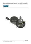
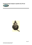
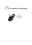
Compact Joystick Advanced, CJA R-net
Spare part no: 1822772
CJA R-net
1. General
The Compact Joystick Advanced R-net (CJA R-net) is an input device and is coupled to
the R-net wheelchair electronics.
•
It’s a proportional joystick module with an adjustable hand pad in a small housing.
•
The joystick D50800 from PG Drive Technology is used. It is a very reliable contact
less joystick which meets the most rigid requirements
•
The CJA R-net can be adjusted to any individual need and possibility of the user.
This can be done by adjusting the ‘Throw’ parameters of the R-net system.
•
We can install the CJA R-net in a good position through the mounting kit.
•
Because the CJA R-net has a standard shaft diameter, it will accept adaptive knobs
available on the market.
•
The CJA R-net can be directly connected to the R-net system.
•
The CJA R-net is completely protected against moisture, which makes it suitable to
use outdoors.
Page: 1/19
User manual Compact Joystick Advanced R-net
Art.no: 205311-US-0, Edition 2. 2009-10
2. Operation
2.1 Introduction
The CJA R-net is a joystick module that can directly be connected to the R-net control
system of PG Drives Technology (PDGT). So we refer to the R-net Control System
Technical Manual – SK77981 – from PGDT.
The relevant contents of this chapter should be included in the wheelchair operating guide.
Further copies are available from Permobil Inc in either written or disk (Adobe PDF)
format. Copies of the SK77981 of PGDT are available from PGDT in either written or disk
(Adobe PDF) format. Copies of these 2 documents should not be made without the
expressed permission of Permobil Inc or PGDT.
The operation of the R-net varies dependent on programming. This chapter covers the
special types of operation for the CJA R-net. For a complete description of the system we
refer again to the SK77981 of PGDT. It is the responsibility of the wheelchair manufacturer
or local dealer to ensure that only the relevant sections of this chapter are included in the
wheelchair’s operating manual.
Please read this chapter carefully - it will help you to keep your wheelchair reliable and
safe.
2.2 General
An R-net control system comprises a minimum of two modules - Joystick Module and
Power Module. Because of the modular design, the depth of the control system can be
greatly increased. The following diagram shows the basic set-up.
2.2.1 Handling
Avoid knocking your control system and especially the joystick. Be careful not to strike
obstacles with the control system or joystick when you drive. Never drop the control
system.
When transporting your wheelchair, make sure that the control system is well protected.
Avoid damage to cables.
Page: 2/19
User manual Compact Joystick Advanced R-net
Art.no: 205311-US-0, Edition 2. 2009-10
2.2.2 Operating Conditions
Your control system uses industrial-grade components throughout, ensuring reliable
operation in a wide range of conditions. However, you will improve the reliability of the
control system if you keep exposure to extreme conditions to a minimum.
Do not expose your control system or its components to damp for prolonged periods. If the
control system becomes contaminated with food or drink clean it off as soon as possible.
2.2.3 Cleaning
Clean the control system and the joystick with a cloth dampened with diluted detergent. Be
careful when cleaning the joystick.
Never use abrasive or spirit-based cleaners.
2.3 Mating Connectors
To connect the Communication Cables:
Holding the connector housing, firmly push the connector into its mate until you can no
longer see the yellow plastic.
The connectors are secured using a friction system.
To disconnect the Communication Cables:
Holding the connector housing firmly, pull the connectors apart.
Page: 3/19
User manual Compact Joystick Advanced R-net
Art.no: 205311-US-0, Edition 2. 2009-10
2.4 Controls
Most of the controls of the CJA R-net are common to the standard joystick module of
PGDT. The controls typical for the CJA R-net are explained in this section. For the
complete description we refer to the SK77981 of PGDT.
Joystick Module
Jack Sockets
2.4.1 Joystick
The primary function of the joystick is to control the speed and direction of the wheelchair.
The further you push the joystick from the centre position the faster the wheelchair will
move. When you release the joystick the brakes are automatically applied.
If the wheelchair is fitted with actuators, the joystick can also be used to move and select
actuators. Refer to programming manual Art.nr: 205314-US-0 for more details and
different functionalities of the buttons.
2.4.2 Buttons and Led’s
Page: 4/19
User manual Compact Joystick Advanced R-net
Art.no: 205311-US-0, Edition 2. 2009-10
2.4.2.1 On/Off Button
The On/Off button applies power to the control system electronics, which in turn supply
power to the wheelchair’s motors.
Do not use the On/Off button to stop the wheelchair unless there is an emergency. (If you
do, you may shorten the life of the wheelchair drive components).
2.4.2.2 Left Button
Depending on the way the control system has been programmed this key can have
different functions. The factory default function is ‘Mode Drive/Axes’. The ‘Mode
Drive/Axes’ function allows the user to switch between the drive mode and local axes
mode
2.4.2.3 Right Button
Depending on the way the control system has been programmed this key can have
different functions. The factory default function is ‘Next’. The function ‘Next’ allows the
user to select the next profile or the next axis depending in which mode you are at that
moment.
2.4.2.4 External On/Off Switch Jack
This allows the user to turn the control system on and off using an external device, such as
a buddy button.
2.4.2.5 External Profile Switch Jack
Depending on the way the control system has been programmed an external connected
device, such as a buddy button, can have different functions. The factory default function
is ‘Horn’. The horn will sound while the connected switch is pressed – as long as the
standard function is selected.
2.4.2.6 Battery/Service Indicator
In normal operating state this displays the charge available in the battery and can be used
to alert the user to the status of the battery. See CJA State Indication chart. Chapter 3.11
Green Continuous
This indicates that all is well. Battery level is >70%.
Green Long Flashing
This indicates that all is well. Battery level is between 50% and 70%.
Green Short Flashing
This indicates that all is well. Battery level is between 30% and 50%.
Red Continuous
The control system is functioning correctly, but you should charge the battery as
soon as possible. Battery level is <30%.
In addition to the indication of the battery level, the Battery/Service Indicator
displays:
Alternating Green/Red Flashing
The ´slow´ alternating flashing is the reconfiguration, fast flashing is request to
shut down and restart the system. (after adding or removing e.g an extra joystick).
Red Flashing
The system has detected an inhibit.
Page: 5/19
User manual Compact Joystick Advanced R-net
Art.no: 205311-US-0, Edition 2. 2009-10
Green Pulse with Red Failure Indication
The system has detected a failure. Service is required.
No Light
System is off.
2.4.2.7 Status Indicator
This displays the status of the joystick module.
Green Continuous
This indicates that the joystick is in drive mode. In this mode it is possible to drive
and to change profile.
Green Flashing
This indicates that the joystick is in latched drive mode. In this mode it is possible to
drive and to change profile.
Red Continuous
This indicates that the joystick is in non-driving mode. Depending on the depth of
your system you can do various things. Operating your axes is maybe the best
known one.
Red/Green Fast Flashing
This indicates that the joystick is in Drive Axis.
Refer to programming manual Art.nr: 205314-US-0 for more details.
2.4.2.8 Led Bar
The Led Bar displays extra information about the status of the joystick module.
Normal drive or latched mode:
Profile 1
Profile 2
Profile 3
Profile 4
Higher Profiles
If the speed of the wheelchair is being limited; for example, by a raised seat, then
the highest profile–4–LED indicator led will flash.
If the wheelchair is prohibit from driving; for example, be a raised seat, the
profile indicator will turn off when the joystick is out of neutral. When the joystick is
in neutral position, the led’s will show the actual profile.
Joystick out of neutral
Page: 6/19
User manual Compact Joystick Advanced R-net
Art.no: 205311-US-0, Edition 2. 2009-10
Local output mode:
The way to operate you actuators, lights or horn depends on how the CJA is
programmed. Up to 16 different outputs (e.g. recline, left indicator, horn, etc.) can
be programmed. The outputs are located in 4 groups and each group can contains
up to 4 outputs. If you enter the local output mode you need first to select a group.
The group is indicated by a flashing led.
Group 1
Group 2
Group 3
Group 4
After you selected a group you can select the desired output. The output is
indicated by a LED.
Output 1
Output 2
Output 3
Output 4
If your wheelchair is setup to use only up to 4 outputs in 1 group, the group
selection is not needed.
2.5 Diagnostic Screen or Acoustic Feedback
When the control system safety circuits have operated and the control system has been
prevented from moving the wheelchair, a diagnostics code will be displayed.
This indicates a system trip, i.e. the R-net has detected a problem somewhere in the
wheelchair’s electrical system.
All red LED’s will flash periodically alternated with a green flash of the battery/service
indicator. The number of red flashes is an indication of the fault. We refer to the State
Indication Chart. Se Chapter 3.11 in this manual
If the error is not critical, for example the ICS (Intelligent Control System) detects a broken
light, then drive will still be possible, however, an acoustic signal will be produced
intermittently.
Page: 7/19
User manual Compact Joystick Advanced R-net
Art.no: 205311-US-0, Edition 2. 2009-10
2.6 Getting Ready to Drive
- Operate the on/off switch. The Battery/Service indicator and the Led Bar will go through
an initializing process then show the base indications as follows.
- Check that you select a profile which suits you.
- Push the joystick to control the speed and direction of the wheelchair.
Remark! If you push the joystick before or just after you switch the control system on, the
Led Bar will not illuminate and the joystick will bleep. You must release and centre the
joystick to resume normal operation.
2.7 Tips for Using your Control System
2.7.1 Driving - General
Make sure that the control system is mounted securely and that the joystick position is
correct. The hand or limb you use to operate the joystick should be supported, for
example by the joystick modules arm pad. Do not use the joystick as the sole support for
your hand or limb - wheelchair movements and bumps could upset your control.
2.7.2 Driving Technique
The control system interprets your joystick movements and produces appropriate
movements of your wheelchair. You will need very little concentration to control the
wheelchair, which is especially useful if you are inexperienced. One popular technique is
to simply point the joystick in the direction you want to go. The wheelchair will “home-in” on
the direction you push the joystick.
The further you push the joystick away from the rest position, the faster the wheelchair will
go. Releasing the joystick will stop the wheelchair. The intelligent speed control system
minimizes the effects of slopes and different types of terrain.
Remark! The wheelchair user must be capable of driving a wheelchair safely. Permobil
Inc accepts no liability for losses of any kind arising from failure to comply with this
condition.
2.7.3 Slow or sluggish movement
If the wheelchair does not travel at full speed or does not respond quickly enough, and the
battery condition is good, there may be a nonhazardous fault. Contact your service agent.
Page: 8/19
User manual Compact Joystick Advanced R-net
Art.no: 205311-US-0, Edition 2. 2009-10
2.8 Precautions for Use
In the event of the wheelchair moving in an unexpected way RELEASE THE JOYSTICK.
This action will stop the wheelchair under any circumstances.
2.8.1 Hazards
Do not drive the wheelchair:
• Beyond restrictions indicated in your wheelchair user manual, for example maximum
inclines, curb height etc.
• In places or on surfaces where a loss of wheel grip could be hazardous, for example on
wet grassy slopes.
• If you know that the control system or other crucial components require repair.
Although the R-net control system is designed to be extremely reliable and each
unit is rigorously tested during manufacture, the possibility of a system malfunction
always exists (however small the probability). Under some conditions of system
malfunction the control system must (for safety reasons) stop the chair
instantaneously. If there is any possibility of the user falling out of the chair as a
result of a sudden braking action, it is imperative that a restraining device such as a
seat belt is supplied with the wheelchair and that it is in use at all times when the
wheelchair is in motion. Permobil Inc accept no liability for losses of any kind
arising from the unexpected stopping of the wheelchair or arising from the improper
use of the wheelchair or control system.
Do not operate the control system if the chair behaves erratically, or shows
abnormal signs of heating, sparks or smoke. Turn the control system off at once
and consult your service agent. Permobil Inc accepts no liability for losses of any
kind arising from failure to comply with this condition.
Electronic equipment can be affected by Electro Magnetic Interference (EMI). Such
interference may be generated by radio stations, TV stations, other radio
transmitters and cellular phones. If the chair exhibits erratic behaviour due to EMI,
turn the control system off immediately and consult your service agent. Permobil
Inc accepts no liability for losses of any kind arising from failure to comply with this
condition.
It is the responsibility of the chair manufacturer to ensure that the wheelchair
complies with appropriate National and International EMC legislation. Permobil Inc
accepts no liability for losses of any kind arising from failure to comply with this
condition.
The wheelchair user must comply with all wheelchair safety warnings. Permobil Inc
accepts no liability for losses of any kind arising from failure to comply with this
condition.
Page: 9/19
User manual Compact Joystick Advanced R-net
Art.no: 205311-US-0, Edition 2. 2009-10
2.9 Safety Checks
The electronic circuits in your control system have been designed to be extremely safe
and reliable. The on-board microcomputer carries out safety checks at up to 100 times per
second. To supplement this safety monitoring you should carry out the following periodic
checks.
If the control system fails any of these checks, do not use the wheelchair and contact your
service agent.
2.9.1 Daily Checks
Joystick:
- With the control system switched off, check that the joystick is not
bent or damaged and that it returns to the centre when you push and
release it. If there is a problem do not continue with the safety checks
and contact your service agent.
2.9.2 Weekly Checks
Parking brake:
- This test should be carried out on a level floor with at least one meter
clear space around the wheelchair.
- Switch on the control system.
- Check that the LEDs remain on, after initialization and that the
battery gauge is displaying a reasonable amount of charge.
- Push the joystick slowly forwards until you hear the parking brakes
operate. The chair may start to move.
- Immediately release the joystick. You must be able to hear each
parking brake operate within a few seconds.
- Repeat the test a further three times, pushing the joystick slowly
backwards, left and right.
Connectors:
- Make sure that all connectors are securely mated.
Cables:
- Check the condition of all cables and connectors for damage.
Joystick gaiter:
- Check the thin rubber gaiter or boot, around the base of the joystick
shaft, for damage or splitting. Check visually only, do not handle the
gaiter.
Mounting:
- Make sure that all the components of the control system are securely
mounted. Do not over tighten any securing screws.
2.9.3 Servicing
To ensure continued satisfactory service, we suggest you have your wheelchair and
control system inspected by your provider after a period of 1 year from commencement of
service. Contact your provider for details when the inspection is due.
Page: 10/19
User manual Compact Joystick Advanced R-net
Art.no: 205311-US-0, Edition 2. 2009-10
2.10 Programming
The control system can be programmed to meet your needs. Programming can be
performed using the R-net programmer software and dongle/programming key.
If you re-program your control system, make sure that you observe any restrictions given
in your wheelchair user manual. Note any changes you make for future reference.
Remark! Programming should only be conducted by healthcare professionals with indepth knowledge of PGDT electronic control systems and the CJA R-net. Incorrect
programming could result in an unsafe set-up of a wheelchair for a user. Permobil Inc
accepts no liability for losses of any kind if the programming of the control system is
altered from factory pre-set values.
Refer to programming manual Art.nr: 205314-US-0 for more details.
2.11 Servicing
All repairs and servicing must be carried out by authorized service personnel. Opening or
making any unauthorized adjustments or modifications to the control system or its
components will invalidate any warranty and may result in hazards to yourself or other
people, and is strictly forbidden.
Permobil Inc accepts no liability for losses of any kind arising from unauthorized opening,
adjustment or modifications to the R-net control system.
If the control system is damaged in any way, or if internal damage may have occurred
through impact or dropping, have the product checked by qualified personnel before
operating. Permobil Inc accepts no liability for losses of any kind arising from failure to
comply with this condition.
2.12 Warranty
The CJA R-net is covered by a warranty period defined by the service agent. For details
of the warranty period, please contact your service agent.
The warranty will be void if the CJA R-net has:
- Not been used in accordance with the CJA R-net user manual – this manual – of
Permobil Inc.
- Not been used in accordance with the R-net control system Technical Manual, SK77981,
of PGDT.
- Been subject to misuse or abuse.
- Been modified or repaired by non-authorized persons.
Page: 11/19
User manual Compact Joystick Advanced R-net
Art.no: 205311-US-0, Edition 2. 2009-10
3. Installation
3.1 R-net Operation
Study Chapter 2. It is important that the operation information in Chapter 2 is supplied,
either as part of the wheelchair user handbook or as a separate document.
3.2 Program Settings
It is the wheelchair manufacturer’s or dealer responsibility to program the control system to
suit the vehicle model and ensure safe operation in compliance with relevant legal
requirements over the whole of the operating range. Permobil Inc accepts no liability for
losses of any kind due to failure to, or incorrect programming of the R-net Control System.
Refer to programming manual Art.nr: 205314-US-0 for more details.
Programming should only be conducted by healthcare professionals with in-depth
knowledge of PGDT electronic control systems and of the CJA R-net of Permobil
Inc, incorrect programming could result in an unsafe setup of a wheelchair for the
user.
3.3 Connections
The following is a selection of the most common configurations
3.3.1 Control Configurations
3.3.1.1 Basic Configuration
Consists of a Power Module, a Communication Cable and a Joystick Module.
Page: 12/19
User manual Compact Joystick Advanced R-net
Art.no: 205311-US-0, Edition 2. 2009-10
3.3.1.2 Joystick & ICS (Intelligent Control System) Configuration
This consists of a Power Module, an Intelligent Seating/Lighting Module (ICS),
3 Communication Cables, R-net connection block and a Joystick Module.
Power Module
Intelligent Control System (ICS)
Joystick Module
3.4 Mounting
3.4.1 Joystick Module Mounting
3.4.1.1 General
The Joystick Module should be secured using M4 screws with a maximum penetration of
8mm or M5 screws with a maximum penetration of 10mm. The M4 screws have a pitch
circular diameter (PCD) of 32mm. The M5 screws 1-3-5 and 2-4 have a distance between
each other of 40mm.
3.4.2 Power Module and ICS Mounting
Contact your provider or Permobil Inc if you need further information and advice.
3.4.3 Cables
The cables to the different modules must be routed and secured in such a way as to
prevent damage to them, for example by cutting or crushing.
Contact your provider or Permobil Inc if you need further information and advice.
Page: 13/19
User manual Compact Joystick Advanced R-net
Art.no: 205311-US-0, Edition 2. 2009-10
3.5 Joystick Module Wiring
The Joystick Module is connected to the Power Module with a Communication Cable.
To connect the Communication Cables:
- Holding the connector housing, firmly push the connector into its mate until you can no
longer see the yellow plastic. The connectors are secured using a friction system.
To disconnect the Communication Cables:
- Holding the connector housing firmly, pull the connectors apart.
3.6 Power Module & ICS Wiring
Contact your provider or Permobil Inc. if you need further information and advice.
3.7 Programming Connection
3.7.1 PC Programming
To utilize the R-net PC Programming Suite the R-net Dongle must first be connected in the
communications system as shown. A USB cable can then be connected between the
Dongle and a PC with the R-Net PC Programmer installed.
Refer to programming manual Art.nr: 205314-US-0 for more details.
Page: 14/19
User manual Compact Joystick Advanced R-net
Art.no: 205311-US-0, Edition 2. 2009-10
3.8 Functionality Tests
Perform the following tests, in order, on each wheelchair before dispatch.
These tests should be conducted in an open space and a restraining device such as
a seat belt should always be used. Permobil Inc accepts no liability for losses of any
kind arising from failure to comply with this condition.
3.8.1 Joystick and Gaiter
- Check that the joystick is not bent or damaged.
- Check the thin rubber gaiter or boot, around the base of the joystick shaft, for damage or
splitting. Check visually only, do not handle the gaiter.
- Check that the joystick returns to the centre position when you push and release it.
3.8.2 Operational Test
This test should be carried out on a level floor with at least one meter clear space around
the wheelchair.
- Switch on the control system.
- Check that the battery gauge remains on, or flashes, after one second.
- Push the joystick slowly forwards until you hear the parking brakes operate. The chair
may start to move.
- Immediately release the joystick. You must be able to hear each parking brake operate
within a few seconds.
- Repeat the test a further three times, pushing the joystick slowly backwards, left and
right.
3.8.3 Test Drive
- Drive the wheelchair and make sure that it operates correctly for all positions of the user
controls.
3.8.4 Soft-Stop Test
- Drive the wheelchair at full forward speed and switch the control system off.
- The wheelchair must not stop suddenly, but should decelerate to standstill.
3.9 Electromagnetic Compatibility (E.M.C.)
The CJA R-net has been tested on a generic wheelchair for compliance with EC directive
89/336/EEC, and the EMC requirements of EN12184.
3.10 Battery Gauge
Refer to Chapter 2 for how to read the battery gauge.
The battery gauge becomes red when the battery voltage falls below 23.3V whilst the
wheelchair is driving on a level surface.
Page: 15/19
User manual Compact Joystick Advanced R-net
Art.no: 205311-US-0, Edition 2. 2009-10
3.11 State Indication Chart CJA R-net
Page: 16/19
User manual Compact Joystick Advanced R-net
Art.no: 205311-US-0, Edition 2. 2009-10
Table of Content:
Compact Joystick Advanced, CJA R-net .............................................................................1
1. General ............................................................................................................................1
2. Operation .........................................................................................................................2
2.1 Introduction ................................................................................................................2
2.2 General ......................................................................................................................2
2.2.1 Handling...............................................................................................................2
2.2.2 Operating Conditions ...........................................................................................3
2.2.3 Cleaning...............................................................................................................3
2.3 Mating Connectors .....................................................................................................3
2.4 Controls......................................................................................................................4
2.4.1 Joystick................................................................................................................4
2.4.2 Buttons and Led’s ................................................................................................4
2.4.2.1 On/Off Button ................................................................................................5
2.4.2.2 Left Button.....................................................................................................5
2.4.2.3 Right Button ..................................................................................................5
2.4.2.4 External On/Off Switch Jack..........................................................................5
2.4.2.5 External Profile Switch Jack..........................................................................5
2.4.2.6 Battery/Service Indicator ...............................................................................5
Green Continuous..............................................................................................................5
Green Long Flashing .........................................................................................................5
Green Short Flashing ........................................................................................................5
Red Continuous .................................................................................................................5
Alternating Green/Red Flashing .......................................................................................5
Red Flashing ......................................................................................................................5
The system has detected an inhibit......................................................................................5
Green Pulse with Red Failure Indication .........................................................................6
No Light ..............................................................................................................................6
System is off. .......................................................................................................................6
2.4.2.7 Status Indicator .............................................................................................6
Green Continuous..............................................................................................................6
Green Flashing...................................................................................................................6
Red Continuous .................................................................................................................6
Red/Green Fast Flashing...................................................................................................6
2.4.2.8 Led Bar..........................................................................................................6
Normal drive or latched mode: .........................................................................................6
2.5 Diagnostic Screen or Acoustic Feedback...................................................................7
2.6 Getting Ready to Drive ...............................................................................................8
2.7 Tips for Using your Control System............................................................................8
2.7.1 Driving - General..................................................................................................8
2.7.2 Driving Technique................................................................................................8
2.7.3 Slow or sluggish movement .................................................................................8
2.8 Precautions for Use....................................................................................................9
2.8.1 Hazards ...............................................................................................................9
2.9 Safety Checks ..........................................................................................................10
2.9.1 Daily Checks......................................................................................................10
2.9.2 Weekly Checks..................................................................................................10
2.9.3 Servicing............................................................................................................10
Page: 17/19
User manual Compact Joystick Advanced R-net
Art.no: 205311-US-0, Edition 2. 2009-10
2.10 Programming..........................................................................................................11
2.11 Servicing ................................................................................................................11
2.12 Warranty.................................................................................................................11
3. Installation......................................................................................................................12
3.1 R-net Operation........................................................................................................12
3.2 Program Settings......................................................................................................12
3.3 Connections .............................................................................................................12
3.3.1 Control Configurations .......................................................................................12
3.3.1.1 Basic Configuration .....................................................................................12
3.3.1.2 Joystick & ICS (Intelligent Control System) Configuration...........................13
3.4 Mounting ..................................................................................................................13
3.4.1 Joystick Module Mounting..................................................................................13
3.4.1.1 General .......................................................................................................13
3.4.2 Power Module and ICS Mounting ......................................................................13
3.4.3 Cables ...............................................................................................................13
3.5 Joystick Module Wiring.............................................................................................14
3.6 Power Module & ICS Wiring....................................................................................14
3.7 Programming Connection.........................................................................................14
3.8 Functionality Tests ...................................................................................................15
3.8.1 Joystick and Gaiter ............................................................................................15
3.8.2 Operational Test ................................................................................................15
3.8.3 Test Drive ..........................................................................................................15
3.8.4 Soft-Stop Test....................................................................................................15
3.9 Electromagnetic Compatibility (E.M.C.)....................................................................15
3.10 Battery Gauge ........................................................................................................15
3.11 State Indication Chart CJA R-net ...........................................................................16
Page: 18/19
User manual Compact Joystick Advanced R-net
Art.no: 205311-US-0, Edition 2. 2009-10
HEADOFFICE
Permobil AB
BOX 120
Per Uddéns väg 20
SE-861 23 Timrå
Tel +46 60 59 59 00
Fax +46 60 57 52 50
[email protected]
FRANCE
Permobil sarl
225, rue Tourmaline
Pôle d’Activités Nord
FR-13510 Eguilles
Tel +33 4 42 52 80 30
Fax +33 4 42 52 80 31
[email protected]
PERMOBIL EUROPE
BV
De Doom 22
NL-6419 CX Heerlen
Tel +31(0) 45 564 54 90
Fax +31(0) 45 564 5491
[email protected]
GREECE
Scan Ideal S.A.
28 Tzavela str
GR-54249 Thessaloniki
Tel +30 231 0320 150
Fax +30 231 0320 151
[email protected]
BELGIEN
Permobil Benelux BV
Beitel 11
NL-6466GZ Kerkrade
Tel +31(0) 45 564 54 80
Fax +31(0) 45 564 54 81
[email protected]
HONGKONG
3-Med Medical
Instruments Co., Ltd.
26 D, Kin Ga Ind.
Building
no 9 San On St.
Tuen Mun, N.T.
Tel +852 2458 3648
Fax +852 2424 6541
[email protected]
AUSTRALIA
Northcott Dynamic
Living Designs
No. 1 Fennell Street
North Parramatta
NSW, 2151 Australië
Tel +61 2 9890 0100
Fax +61 2 9683 2827
[email protected]
ICELAND
Stod Hf
Trönuhrauni 8
IS-220 Hafnarfirdi
Tel +354 565 28 85
Fax +354 565 14 23
DENMARK
Permobil AS
Måløv
Tel +45 44 68 14 06
Fax +45 44 68 24 06
[email protected]
IRAN
Iran Majin Co. Ltd
No 114, W. Kayhan St.
15776 Tehran
Tel +98 21 875 8583
Fax +98 21 875 8584
GERMANY
Permobil GmbH
Freie Vogel Strasse 393
DE- 44269 Dortmund
Tel+ 49 231 945363 0
Fax +49 231 945363 70
[email protected]
ITALY
Permobil Italy
Via Tartini 5/D
I-50144 Firenze
Tel +39 055 36 05 62
Fax +39 055 324 60 59
[email protected]
JAPAN
Permobil K.K.
Akasaka wing bld 1F
Minato-Wad
Akasaka 6-6-15
107-0052 Tokyo
Japan
Tel +81 3 5603678
Fax+81 3 5603679
NORWAY
Permobil AS
Hvamsvingen 22
NO-2013 Skjetten
Tel. +47 48 12 90 00
Fax +47 63 84 48 50
[email protected]
AUSTRIA
Permobil GmbH
Flüelistraße 10
CH-6064 Kerns
Tel +41 41 662 06 00
Fax +41 41 662 06 02
PORTUGAL
Mobilitec, Lda
Rua dos Verdes, 123
Pedras Rubras
PT-4470-6578 MoreiraMaia
Tel +351 22 943 61 30
Fax +351 22 943 61 39
[email protected]
TURKEY
Hakemannltd . Sti.
Abdulah Cevdet Sk. 39/7-8
TR-06550Çankaya Ankara
Tel +90 312 440 06 32
Fax +90 312 439 96 91
UK
Permobil Ltd.
Unit 4, West Vale Building
Wakefield Rd
GB-Brighouse HD6 1PE
Tel +44 1484 722 888
Fax+44 1484 723 013
[email protected]
USA
Permobil Inc
6961 Eastgate Blvd
US-37090 Lebanon TN
Tel +1 800 736 0925
Fax +1 800 231 3256
[email protected]
SOUTH-KOREA
ATN Corporation
1006, Yongsan Jun Ja B/D
16-58 Hankagro–3Ka
Yongsan-Ku Seoel
Tel +82 2 714 8030
Fax +82 2704 8030
Atncorpnetsgo.com
SWEDEN
Permobil Försäljning &
SPAIN
Service AB
Mobilitec, Lda
Box 120
Rua dos Verdes, 123
Per Uddéns väg 20
Pedras Rubras
SE-861 23 Timrå
PT-4470-658 Moreira- Tel +46 60 59 59 00
Maia
Fax +46 60 57 52 50
Tel +351 22 943 61 30
Fax +351 22 943 61 39 SWITSERLAND
[email protected]
Permobil AG
Flüelistraße 10
CH-6064 kerns
Tel +41 41 662 06 00
Fax +41 41 662 06 02
[email protected]
FINLAND
Algol Pharma Ab
Pharmaceutical Division
13 P.O. Box
Karapellontie 6
FI-02611 Espoo
Tel +358 9 509 91
Fax +358 9 509 92 58
Page: 19/19
User manual Compact Joystick Advanced R-net
Art.no: 205311-US-0, Edition 2. 2009-10