1
μC/ TCP-IP
TM
The Embedded Protocol Stack
User’s Manual
v2.13.02
Micriμm
1290 Weston Road, Suite 306
Weston, FL 33326
USA
www.Micrium.com
Designations used by companies to distinguish their products are often claimed as
trademarks. In all instances where Micriμm Press is aware of a trademark claim, the product
name appears in initial capital letters, in all capital letters, or in accordance with the
vendor’s capatilization preference. Readers should contact the appropriate companies for
more complete information on trademarks and trademark registrations. All trademarks and
registerd trademarks in this book are the property of their respective holders.
Copyright © 2013 by Micriμm except where noted otherwise. All rights reserved. Printed in
the United States of America. No part of this publication may be reproduced or distributed
in any form or by any means, or stored in a database or retrieval system, without the prior
written permission of the publisher; with the exception that the program listings may be
entered, stored, and executed in a computer system, but they may not be reproduced for
publication.
The programs and code examples in this book are presented for instructional value. The
programs and examples have been carefully tested, but are not guaranteed to any particular
purpose. The publisher does not offer any warranties and does not guarantee the accuracy,
adequacy, or completeness of any information herein and is not responsible for any errors
and ommissions. The publisher assumes no liability for damages resulting from the use of
the information in this book or for any infringement of the intellectual property rights of
third parties that would result from the use of this information.
600-uC-TCP-IP-010
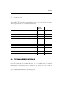
Table of Contents
Chapter 1
1-1
1-2
1-3
1-4
1-5
1-6
1-7
1-8
1-9
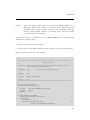
Introduction to µC/TCP-IP ...................................................................... 21
Portable ................................................................................................... 21
Scalable ................................................................................................... 21
Coding Standards ................................................................................... 22
MISRA C .................................................................................................. 22
Safety Critical Certification ..................................................................... 22
RTOS ........................................................................................................ 23
Network Devices ..................................................................................... 23
µC/TCP-IP Protocols ............................................................................... 24
Application Protocols .............................................................................. 24
Chapter 2
2-1
2-1-1
2-1-2
2-1-3
2-1-4
2-1-5
2-1-6
2-1-7
2-1-8
2-1-9
2-1-10
2-2
2-2-1
2-2-2
2-2-3
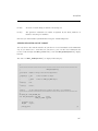
µC/TCP-IP Architecture .......................................................................... 26
µC/TCP-IP Module Relationships ........................................................... 28
Application ........................................................................................... 28
µC/LIB Libraries ................................................................................... 28
BSD Socket API Layer ......................................................................... 29
TCP/IP Layer ........................................................................................ 29
Network Interface (IF) Layer ................................................................ 30
Network Device Driver Layer ............................................................... 31
Network Physical (PHY) Layer ............................................................. 31
Network Wireless Manager ................................................................. 31
CPU Layer ............................................................................................ 31
Real-Time Operating System (RTOS) Layer ....................................... 32
Task Model .............................................................................................. 33
µC/TCP-IP Tasks and Priorities ........................................................... 33
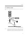
Receiving a Packet .............................................................................. 35
Transmitting a Packet .......................................................................... 38
3
Chapter 3
3-1
3-2
3-3
3-4
3-5
3-6
3-7
3-8
3-9
3-10
3-11
3-12
3-13
3-14
3-15
3-16
3-17
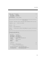
Directories and Files ............................................................................... 41
Block Diagram ......................................................................................... 42
Application Code ..................................................................................... 43
CPU .......................................................................................................... 45
Board Support Package (BSP) ............................................................... 46
Network Board Support Package (NET_BSP) ....................................... 47
μC/OS-III, CPU Independent Source Code ............................................ 49
μC/OS-III, CPU Specific Source Code ................................................... 50
μC/CPU, CPU Specific Source Code ..................................................... 51
μC/LIB, Portable Library Functions ........................................................ 53
μC/TCP-IP Network Devices .................................................................. 54
μC/TCP-IP Network Interface ................................................................. 56
μC/TCP-IP Network File System abstraction layer ................................ 57
μC/TCP-IP Network OS Abstraction Layer ............................................ 58
μC/TCP-IP Network CPU Specific Code ................................................ 59
μC/TCP-IP Network CPU Independent Source Code ........................... 60
μC/TCP-IP Network Security Manager CPU Independent Source Code .. 61
Summary .................................................................................................. 62
Chapter 4
4-1
4-2
4-3
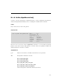
Getting Started with μC/TCP-IP ............................................................. 67
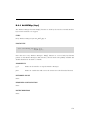
Installing μC/TCP-IP ................................................................................ 67
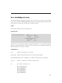
μC/TCP-IP Example Project ................................................................... 68
Application Code ..................................................................................... 69
Chapter 5
5-1
5-1-1
5-1-2
5-1-3
5-1-4
5-1-5
5-2
5-2-1
5-2-2
5-3
5-3-1
5-3-2
5-3-3
Network Interface Configuration ............................................................ 77
Buffer Management ................................................................................ 77
Network Buffers ................................................................................... 77
Receive Buffers .................................................................................... 77
Transmit Buffers ................................................................................... 78
Network Buffer Architecture ................................................................ 78
Network Buffer Sizes ........................................................................... 80
μC/TCP-IP Network Interface configuration .......................................... 85
Memory Configuration ......................................................................... 85
μC/TCP-IP Memory Management ....................................................... 89
Ethernet Interface Configuration ............................................................ 90
Ethernet Device Configuration ............................................................ 90
Ethernet PHY Configuration ................................................................ 92
Adding an Ethernet Interface ............................................................... 94
4
5-4
5-4-1
5-4-2
5-5
5-5-1
5-5-2
5-6
5-6-1
5-6-2
5-6-3
5-6-4
5-6-5
5-6-6
5-6-7
5-6-8
5-6-9
5-6-10
5-6-11
5-6-12
Wireless Interface Configuration ............................................................ 98
Wireless Device Configuration ............................................................ 98
Adding a Wireless Interface ............................................................... 100
LoopBack Interface Configuration ....................................................... 104
Loopback Configuration .................................................................... 104
Adding a Loopback Interface ............................................................ 107
Network Interface API ........................................................................... 108
Configuring an IP Address ................................................................. 108
Starting Network Interfaces ............................................................... 110
Stopping Network Interfaces ............................................................. 111
Getting Network Interface MTU ........................................................ 112
Setting Network Interface MTU ......................................................... 112
Getting Network Interface Hardware Addresses .............................. 113
Setting Network Interface Hardware Address .................................. 114
Getting Link State .............................................................................. 115
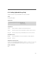
Scanning for a Wireless Access Point .............................................. 116
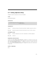
Joining Wireless Access Point .......................................................... 117
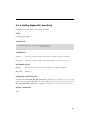
Creating Wireless Ad Hoc Access Point ........................................... 119
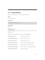
Leaving Wireless Access Point ......................................................... 120
Chapter 6
6-1
6-1-1
6-1-2
6-1-3
6-1-4
6-1-5
6-2
6-2-1
6-2-2
6-2-3
6-2-4
6-2-5
6-2-6
6-2-7
6-2-8
6-2-9
6-2-10
Network Board Support Package ........................................................ 121
Ethernet BSP Layer ............................................................................... 122
Description of the Ethernet BSP API ................................................ 122
Configuring Clocks for an Ethernet Device ...................................... 125
Configuring General I/O for an Ethernet Device ............................... 125
Configuring the Interrupt Controller for an Ethernet Device ............ 126
Getting a Device Clock Frequency .................................................... 127
Wireless BSP Layer ............................................................................... 127
Description of the Wireless BSP API ................................................ 127
Configuring General-Purpose I/O for a Wireless Device .................. 133
Starting a Wireless Device ................................................................. 133
Stopping a Wireless Device ............................................................... 133
Configuring the Interrupt Controller for a Wireless Device .............. 134
Enabling and Disabling Wireless Interrupt ........................................ 134
Configuring the SPI Interface ............................................................ 135
Setting SPI Controller for a Wireless device ..................................... 135
Locking and Unlocking SPI Bus ........................................................ 136
Enabling and Disabling SPI Chip select ............................................ 136
5
6-2-11
6-3
6-4
Writing and Reading to the SPI Bus .................................................. 136
Specifying the Interface Number of the Device ISR ............................ 137
Miscellaneous Network BSP ................................................................ 138
Chapter 7
7-1
7-2
7-2-1
7-2-2
7-2-3
7-2-4
7-2-5
7-3
7-4
7-4-1
7-4-2
7-4-3
7-4-4
7-4-5
7-4-6
7-4-7
7-5
7-5-1
7-5-2
7-5-3
7-5-4
7-5-5
7-5-6
7-5-7
7-5-8
7-5-9
7-5-10
7-5-11
7-5-12
7-6
7-6-1
7-6-2
7-6-3
Device Driver Implementation .............................................................. 139
Concepts ............................................................................................... 140
Overview of the μC/TCP-IP Interface Layers ....................................... 142
Configuration Structures and APIs interactions ............................... 142
μC/TCP-IP Memory Management ..................................................... 146
Interrupt Handling .............................................................................. 149
Network Packet Reception Overview ............................................... 151
Network Packet Transmission Overview .......................................... 152
Ethernet Layers Interactions ................................................................. 154
Ethernet PHY API Implementation ....................................................... 155
Description of the Ethernet PHY API ................................................ 155
How to Initialize the PHY ................................................................... 156
How Enable Or Disable the PHY ....................................................... 156
How to Get the Network Link State ................................................... 156
How to Set the Link Speed and Duplex ............................................ 157
How to Specify the Address of the PHY ISR .................................... 157
NetPhy_ISR_Handler() ........................................................................ 157
Ethernet Device Driver Implementation ............................................... 158
Description of the Ethernet Device Driver API .................................. 158
Initializing a network device .............................................................. 161
Starting a Network Device ................................................................. 162
Stopping a Network Device ............................................................... 163
NetDev_ISR_Handler() ....................................................................... 164
Receiving Packets on a Network Device .......................................... 165
Transmitting Packets on a Network Device ...................................... 166
Adding an Address to Multicast Address Filter of a Network Device ........ 166
Removing an Address from Multicast Address Filter of a Network Device .. 170
Setting the MAC Link, Duplex and Speed Settings .......................... 171
Reading PHY Registers ..................................................................... 171
Writing to PHY Registers ................................................................... 171
Ethernet - Transmitting & Receiving using DMA ................................. 172
Driver Data & Control Using DMA ..................................................... 174
Reception using DMA ........................................................................ 174
Reception Using DMA with Lists ....................................................... 185
6
7-6-4
7-7
7-7-1
7-7-2
7-8
7-9
7-10
7-10-1
7-10-2
7-10-3
7-10-4
7-10-5
7-10-6
7-10-7
7-10-8
7-10-9
7-10-10
7-10-11
7-10-12
7-10-13
Transmission using DMA ................................................................... 196
Ethernet - Transmitting and Receiving using Memory Copy .............. 204
Reception using Memory Copy ......................................................... 204
Transmission using Memory Copy .................................................... 209
Wireless Layers Interaction .................................................................. 211
Wireless Manager API Implementation ................................................ 212
Wireless Device Driver Implementation ............................................... 216
Description of the Wireless Device Driver API ................................. 216
How to Access the SPI Bus ............................................................... 217
Initializing a Network Device ............................................................. 218
Starting a Network Device ................................................................ 219
Stopping a Network Device ............................................................... 221
Handling a Wireless Device ISR ........................................................ 221
Receiving Packets and Management Frames .................................. 222
Transmitting Packets ......................................................................... 225
Adding an Address to Multicast Address Filter of a Network Device .... 226
Removing an Address from Multicast Address Filter of a Network Device .. 226
How to Demultiplex Management Frames ....................................... 226
How to Execute Management Command ......................................... 227
How to Process Management Response ......................................... 228
Chapter 8
8-1
8-2
8-2-1
8-2-2
8-3
8-3-1
8-3-2
8-3-3
8-3-4
8-3-5
8-3-6
8-4
8-4-1
8-4-2
8-5
8-5-1
Device Driver Validation ........................................................................ 229
Checklist ................................................................................................ 230
Test Management Interface .................................................................. 230
NDIT Main Window ............................................................................ 232
General Options Tab .......................................................................... 234
Validating a Device Driver ..................................................................... 234
Files Needed ...................................................................................... 235
Project Example ................................................................................. 236
Hardware Address configuration ...................................................... 237
IF Start / Stop ..................................................................................... 239
ICMP Echo Request (Ping) Tests ...................................................... 241
Target Board Configuration ............................................................... 242
Using IPerf ............................................................................................. 242
Getting Started with IPerf .................................................................. 243
IPerf Tools .......................................................................................... 244
IPerf Test Case ...................................................................................... 253
Testing UDP Transmission ................................................................ 257
7
8-5-2
8-5-3
8-5-4
8-6
8-6-1
8-6-2
8-6-3
Testing UDP Reception ..................................................................... 260
Testing TCP Transmission ................................................................. 264
Testing TCP Reception ...................................................................... 265
Multicast ................................................................................................ 268
Multicast Test Setup .......................................................................... 268
Multicast Test Using NDIT ................................................................. 269
Analyzing the Results ........................................................................ 270
Chapter 9
9-1
9-2
9-3
9-3-1
9-3-2
9-4
9-4-1
9-5
9-6
9-7
9-7-1
9-7-2
Socket Programming ............................................................................ 273
Network Socket Data Structures .......................................................... 273
Complete send() Operation ................................................................... 276
Socket Applications .............................................................................. 277
Datagram Socket (UDP Socket) ........................................................ 278
Stream Socket (TCP Socket) ............................................................. 283
Socket Configuration ............................................................................ 289
Socket Options .................................................................................. 290
Secure Sockets ..................................................................................... 291
2MSL ...................................................................................................... 291
μC/TCP-IP Socket Error Codes ............................................................ 292
Fatal Socket Error Codes .................................................................. 292
Socket Error Code List ...................................................................... 292
Chapter 10 Timer Management ............................................................................... 293
Chapter 11 Debug Management .............................................................................. 296
11-1
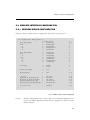
Network Debug Information Constants ............................................... 296
11-2
Network Debug Monitor Task ............................................................... 297
Chapter 12 Statistics and Error Counters ............................................................... 298
12-1
Statistics ................................................................................................ 298
12-2
Error Counters ....................................................................................... 300
Appendix A μC/TCP-IP Ethernet Device Driver APIs ............................................... 301
A-1
Device Driver Functions for MAC ......................................................... 302
A-1-1
NetDev_Init() ....................................................................................... 302
A-1-2
NetDev_Start() .................................................................................... 305
8
A-1-3
A-1-4
A-1-5
A-1-6
A-1-7
A-1-8
A-1-9
A-1-10
A-1-11
A-2
A-2-1
A-2-2
A-2-3
A-2-4
A-2-5
A-3
A-3-1
A-3-2
A-3-3
A-3-4
A-3-5
NetDev_Stop() .................................................................................... 308
NetDev_Rx() ........................................................................................ 310
NetDev_Tx() ........................................................................................ 312
NetDev_AddrMulticastAdd() .............................................................. 314
NetDev_AddrMulticastRemove() ....................................................... 318
NetDev_ISR_Handler() ....................................................................... 320
NetDev_IO_Ctrl() ................................................................................. 322
NetDev_MII_Rd() ................................................................................ 324
NetDev_MII_Wr() ................................................................................. 326
Device Driver Functions for PHY .......................................................... 328
NetPhy_Init() ....................................................................................... 328
NetPhy_EnDis() ................................................................................... 330
NetPhy_LinkStateGet() ....................................................................... 331
NetPhy_LinkStateSet() ....................................................................... 333
NetPhy_ISR_Handler() ........................................................................ 335
Device Driver BSP Functions ................................................................ 336
NetDev_CfgClk() ................................................................................. 336
NetDev_CfgGPIO() ............................................................................. 338
NetDev_CfgIntCtrl() ............................................................................ 340
NetDev_ClkGetFreq() ......................................................................... 344
NetDev_ISR_Handler() ....................................................................... 346
Appendix B μC/TCP-IP Wireless Device Driver APIs ............................................... 349
B-1
Device Driver Functions for Wireless Module ...................................... 350
B-1-1
NetDev_Init() ....................................................................................... 350
B-1-2
NetDev_Start() .................................................................................... 352
B-1-3
NetDev_Stop() .................................................................................... 355
B-1-4
NetDev_Rx() ........................................................................................ 357
B-1-5
NetDev_Tx() ........................................................................................ 360
B-1-6
NetDev_AddrMulticastAdd() .............................................................. 362
B-1-7
NetDev_AddrMulticastRemove() ....................................................... 366
B-1-8
NetDev_ISR_Handler() ....................................................................... 368
B-1-9
NetDev_MgmtDemux() ....................................................................... 370
B-1-10
NetDev_MgmtExecuteCmd() ............................................................. 372
B-1-11
NetDev_MgmtProcessResp() ............................................................ 374
B-2
Wireless Manager API ........................................................................... 376
B-2-1
NetWiFiMgr_Init() ................................................................................ 376
B-2-2
NetWiFiMgr_Start() ............................................................................. 377
9
B-2-3
B-2-4
B-2-5
B-2-6
B-2-7
B-2-8
B-3
B-3-1
B-3-2
B-3-3
B-3-4
B-3-5
B-3-6
B-3-7
B-3-8
B-3-9
B-3-10
B-3-11
B-3-12
B-3-13
NetWiFiMgr_Stop() ............................................................................. 378
NetWiFiMgr_AP_Scan() ...................................................................... 379
NetWiFiMgr_AP_Join() ....................................................................... 381
NetWiFiMgr_AP_Leave() .................................................................... 382
NetWiFiMgr_IO_Ctrl() ......................................................................... 383
NetWiFiMgr_Mgmt() ........................................................................... 385
Device Driver BSP Functions ................................................................ 387
NetDev_WiFi_Start() ........................................................................... 387
NetDev_WiFi_Stop() ........................................................................... 389
NetDev_WiFi_CfgGPIO() .................................................................... 391
NetDev_WiFi_CfgIntCtrl() ................................................................... 393
NetDev_WiFi_IntCtrl() ......................................................................... 397
NetDev_WiFi_SPI_Init() ...................................................................... 399
NetDev_WiFi_SPI_Lock() ................................................................... 401
NetDev_WiFi_SPI_Unlock() ................................................................ 403
NetDev_WiFi_SPI_WrRd() .................................................................. 405
NetDev_WiFi_SPI_ChipSelEn() .......................................................... 407
NetDev_WiFi_SPI_ChipSelDis() ......................................................... 409
NetDev_WiFi_SPI_Cfg() ...................................................................... 411
NetDev_WiFi_ISR_Handler() .............................................................. 414
Appendix C μC/TCP-IP API Reference ..................................................................... 417
C-1
General Network Functions .................................................................. 418
C-1-1
Net_Init() ............................................................................................. 418
C-1-2
Net_InitDflt() ........................................................................................ 419
C-1-3
Net_VersionGet() ................................................................................ 420
C-2
Network Application Interface Functions ............................................. 422
C-2-1
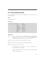
NetApp_SockAccept() (TCP) ............................................................. 422
C-2-2
NetApp_SockBind() (TCP/UDP) ......................................................... 424
C-2-3
NetApp_SockClose() (TCP/UDP) ....................................................... 426
C-2-4
NetApp_SockConn() (TCP/UDP) ........................................................ 428
C-2-5
NetApp_SockListen() (TCP) ............................................................... 430
C-2-6
NetApp_SockOpen() (TCP/UDP) ....................................................... 432
C-2-7
NetApp_SockRx() (TCP/UDP) ............................................................ 434
C-2-8
NetApp_SockTx() (TCP/UDP) ............................................................ 437
C-2-9
NetApp_TimeDly_ms() ........................................................................ 440
C-3
ARP Functions ....................................................................................... 441
C-3-1
NetARP_CacheCalcStat() .................................................................. 441
10
C-3-2
C-3-3
C-3-4
C-3-5
C-3-6
C-3-7
C-3-8
C-3-9
C-3-10
C-4
C-4-1
C-4-2
C-4-3
C-4-4
C-5
C-5-1
C-5-2
C-5-3
C-5-4
C-5-5
C-5-6
C-5-7
C-5-8
C-6
C-6-1
C-6-2
C-6-3
C-7
C-7-1
C-7-2
C-7-3
C-7-4
C-7-5
C-7-6
C-7-7
C-7-8
C-7-9
C-7-10
NetARP_CacheGetAddrHW() ............................................................. 442
NetARP_CachePoolStatGet() ............................................................ 444
NetARP_CachePoolStatResetMaxUsed() ......................................... 445
NetARP_CfgCacheAccessedTh() ...................................................... 446
NetARP_CfgCacheTimeout() ............................................................. 447
NetARP_CfgReqMaxRetries() ............................................................ 448
NetARP_CfgReqTimeout() ................................................................. 449
NetARP_IsAddrProtocolConflict() ..................................................... 450
NetARP_ProbeAddrOnNet() ............................................................... 451
Network ASCII Functions ...................................................................... 453
NetASCII_IP_to_Str() .......................................................................... 453
NetASCII_MAC_to_Str() ..................................................................... 455
NetASCII_Str_to_IP() .......................................................................... 457
NetASCII_Str_to_MAC() ..................................................................... 459
Network Buffer Functions ..................................................................... 461
NetBuf_PoolStatGet() ......................................................................... 461
NetBuf_PoolStatResetMaxUsed() ..................................................... 462
NetBuf_RxLargePoolStatGet() ........................................................... 463
NetBuf_RxLargePoolStatResetMaxUsed() ....................................... 464
NetBuf_TxLargePoolStatGet() ........................................................... 465
NetBuf_TxLargePoolStatResetMaxUsed() ........................................ 466
NetBuf_TxSmallPoolStatGet() ........................................................... 467
NetBuf_TxSmallPoolStatResetMaxUsed() ........................................ 468
Network Connection Functions ............................................................ 469
NetConn_CfgAccessedTh() ............................................................... 469
NetConn_PoolStatGet() ...................................................................... 470
NetConn_PoolStatResetMaxUsed() .................................................. 471
Network Debug Functions .................................................................... 472
NetDbg_CfgMonTaskTime() ............................................................... 472
NetDbg_CfgRsrcARP_CacheThLo() .................................................. 473
NetDbg_CfgRsrcBufThLo() ................................................................ 474
NetDbg_CfgRsrcBufRxLargeThLo() .................................................. 475
NetDbg_CfgRsrcBufTxLargeThLo() ................................................... 476
NetDbg_CfgRsrcBufTxSmallThLo() ................................................... 477
NetDbg_CfgRsrcConnThLo() ............................................................. 478
NetDbg_CfgRsrcSockThLo() ............................................................. 479
NetDbg_CfgRsrcTCP_ConnThLo() .................................................... 480
NetDbg_CfgRsrcTmrThLo() ............................................................... 481
11
C-7-11
C-7-12
C-7-13
C-7-14
C-7-15
C-7-16
C-7-17
C-7-18
C-7-19
C-8
C-8-1
C-9
C-9-1
C-9-2
C-9-3
C-9-4
C-9-5
C-9-6
C-9-7
C-9-8
C-9-9
C-9-10
C-9-11
C-9-12
C-9-13
C-9-14
C-9-15
C-9-16
C-9-17
C-9-18
C-9-19
C-9-20
C-10
C-10-1
C-10-2
C-10-3
C-10-4
C-11
NetDbg_ChkStatus() .......................................................................... 482
NetDbg_ChkStatusBufs() ................................................................... 484
NetDbg_ChkStatusConns() ................................................................ 485
NetDbg_ChkStatusRsrcLost() / NetDbg_MonTaskStatusGetRsrcLost() .. 488
NetDbg_ChkStatusRsrcLo() / NetDbg_MonTaskStatusGetRsrcLo() .. 490
NetDbg_ChkStatusTCP() ................................................................... 492
NetDbg_ChkStatusTmrs() .................................................................. 494
NetDbg_MonTaskStatusGetRsrcLost() ............................................. 496
NetDbg_MonTaskStatusGetRsrcLo() ................................................ 496
ICMP Functions ..................................................................................... 497
NetICMP_CfgTxSrcQuenchTh() ......................................................... 497
Network Interface Functions ................................................................ 498
NetIF_Add() ......................................................................................... 498
NetIF_AddrHW_Get() .......................................................................... 501
NetIF_AddrHW_IsValid() ..................................................................... 503
NetIF_AddrHW_Set() .......................................................................... 505
NetIF_CfgPerfMonPeriod() ................................................................. 507
NetIF_CfgPhyLinkPeriod() ................................................................. 508
NetIF_GetRxDataAlignPtr() ................................................................ 509
NetIF_GetTxDataAlignPtr() ................................................................ 512
NetIF_IO_Ctrl() .................................................................................... 515
NetIF_IsEn() ........................................................................................ 517
NetIF_IsEnCfgd() ................................................................................ 518
NetIF_ISR_Handler() ........................................................................... 519
NetIF_IsValid() ..................................................................................... 521
NetIF_IsValidCfgd() ............................................................................. 522
NetIF_LinkStateGet() .......................................................................... 523
NetIF_LinkStateWaitUntilUp() ............................................................ 524
NetIF_MTU_Get() ................................................................................ 526
NetIF_MTU_Set() ................................................................................ 527
NetIF_Start() ....................................................................................... 528
NetIF_Stop() ........................................................................................ 529
Wireless Network Interface Function ................................................... 530
NetIF_WiFi_Scan() .............................................................................. 530
NetIF_WiFi_Join() ............................................................................... 532
NetIF_WiFi_CreateAdhoc() ................................................................. 535
NetIF_WiFi_Leave() ............................................................................ 538
IGMP Functions ..................................................................................... 539
12
C-11-1
C-11-2
C-12
C-12-1
C-12-2
C-12-3
C-12-4
C-12-5
C-12-6
C-12-7
C-12-8
C-12-9
C-12-10
C-12-11
C-12-12
C-12-13
C-12-14
C-12-15
C-12-16
C-12-17
C-12-18
C-12-19
C-12-20
C-12-21
C-12-22
C-12-23
C-12-24
C-13
C-13-1
C-13-2
C-13-3
C-13-4
C-13-5
C-13-6
C-13-7
C-13-8
C-13-9
C-13-10
NetIGMP_HostGrpJoin() .................................................................... 539
NetIGMP_HostGrpLeave() ................................................................. 541
IP Functions ........................................................................................... 542
NetIP_CfgAddrAdd() .......................................................................... 542
NetIP_CfgAddrAddDynamic() ............................................................ 544
NetIP_CfgAddrAddDynamicStart() .................................................... 546
NetIP_CfgAddrAddDynamicStop() .................................................... 548
NetIP_CfgAddrRemove() .................................................................... 549
NetIP_CfgAddrRemoveAll() ............................................................... 551
NetIP_CfgFragReasmTimeout() ......................................................... 552
NetIP_GetAddrDfltGateway() ............................................................. 553
NetIP_GetAddrHost() ......................................................................... 554
NetIP_GetAddrHostCfgd() ................................................................. 556
NetIP_GetAddrSubnetMask() ............................................................ 557
NetIP_IsAddrBroadcast() ................................................................... 558
NetIP_IsAddrClassA() ......................................................................... 559
NetIP_IsAddrClassB() ......................................................................... 560
NetIP_IsAddrClassC() ........................................................................ 561
NetIP_IsAddrHost() ............................................................................ 562
NetIP_IsAddrHostCfgd() .................................................................... 563
NetIP_IsAddrLocalHost() ................................................................... 564
NetIP_IsAddrLocalLink() .................................................................... 565
NetIP_IsAddrsCfgdOnIF() .................................................................. 566
NetIP_IsAddrThisHost() ...................................................................... 567
NetIP_IsValidAddrHost() ..................................................................... 568
NetIP_IsValidAddrHostCfgd() ............................................................ 569
NetIP_IsValidAddrSubnetMask() ....................................................... 571
Network Socket Functions ................................................................... 572
NetSock_Accept() / accept() (TCP) .................................................... 572
NetSock_Bind() / bind() (TCP/UDP) ................................................... 574
NetSock_CfgBlock() (TCP/UDP) ........................................................ 577
NetSock_CfgIF() ................................................................................. 579
NetSock_CfgConnChildQ_SizeGet() (TCP) ....................................... 580
NetSock_CfgConnChildQ_SizeSet() (TCP) ........................................ 582
NetSock_CfgSecure() (TCP) ............................................................... 584
NetSock_CfgServerCertKeyInstall() (TCP) ........................................ 586
NetSock_CfgSecureClientCommonName() (TCP) ............................ 588
NetSock_CfgSecureClientTrustCallBack() (TCP) .............................. 590
13
C-13-11
C-13-12
C-13-13
C-13-14
C-13-15
C-13-16
C-13-17
C-13-18
C-13-19
C-13-20
C-13-21
C-13-22
C-13-23
C-13-24
C-13-25
C-13-26
C-13-27
C-13-28
C-13-29
C-13-30
C-13-31
C-13-32
C-13-33
C-13-34
C-13-35
C-13-36
C-13-37
C-13-38
C-13-39
C-13-40
C-13-41
C-13-42
C-13-43
C-13-44
C-13-45
C-13-46
C-13-47
C-13-48
NetSock_CfgRxQ_Size() (TCP/UDP) ................................................. 592
NetSock_CfgTxQ_Size() (TCP/UDP) .................................................. 594
NetSock_CfgTxIP_TOS() (TCP/UDP) ................................................. 596
NetSock_CfgTxIP_TTL() (TCP/UDP) .................................................. 598
NetSock_CfgTxIP_TTL_Multicast() (TCP/UDP) ................................. 600
NetSock_CfgTimeoutConnAcceptDflt() (TCP) .................................. 602
NetSock_CfgTimeoutConnAcceptGet_ms() (TCP) ........................... 604
NetSock_CfgTimeoutConnAcceptSet() (TCP) .................................. 606
NetSock_CfgTimeoutConnCloseDflt() (TCP) ..................................... 608
NetSock_CfgTimeoutConnCloseGet_ms() (TCP) .............................. 610
NetSock_CfgTimeoutConnCloseSet() (TCP) ..................................... 612
NetSock_CfgTimeoutConnReqDflt() (TCP) ....................................... 614
NetSock_CfgTimeoutConnReqGet_ms() (TCP) ................................ 616
NetSock_CfgTimeoutConnReqSet() (TCP) ........................................ 618
NetSock_CfgTimeoutRxQ_Dflt() (TCP/UDP) ..................................... 620
NetSock_CfgTimeoutRxQ_Get_ms() (TCP/UDP) .............................. 622
NetSock_CfgTimeoutRxQ_Set() (TCP/UDP) ..................................... 624
NetSock_CfgTimeoutTxQ_Dflt() (TCP) .............................................. 626
NetSock_CfgTimeoutTxQ_Get_ms() (TCP) ....................................... 628
NetSock_CfgTimeoutTxQ_Set() (TCP) ............................................... 630
NetSock_Close() / close() (TCP/UDP) ................................................ 632
NetSock_Conn() / connect() (TCP/UDP) ............................................ 634
NET_SOCK_DESC_CLR() / FD_CLR() (TCP/UDP) ............................. 637
NET_SOCK_DESC_COPY() (TCP/UDP) ............................................. 639
NET_SOCK_DESC_INIT() / FD_ZERO() (TCP/UDP) ........................... 640
NET_SOCK_DESC_IS_SET() / FD_IS_SET() (TCP/UDP) ................... 641
NET_SOCK_DESC_SET() / FD_SET() (TCP/UDP) .............................. 643
NetSock_GetConnTransportID() ........................................................ 644
NetSock_IsConn() (TCP/UDP) ........................................................... 646
NetSock_Listen() / listen() (TCP) ........................................................ 648
NetSock_Open() / socket() (TCP/UDP) .............................................. 650
NetSock_OptGet() .............................................................................. 653
NetSock_OptSet() ............................................................................... 655
NetSock_PoolStatGet() ...................................................................... 657
NetSock_PoolStatResetMaxUsed() ................................................... 658
NetSock_RxData() / recv() (TCP) NetSock_RxDataFrom() / recvfrom() (UDP) .. 659
NetSock_Sel() / select() (TCP/UDP) ................................................... 663
NetSock_TxData() / send() (TCP) NetSock_TxDataTo() / sendto() (UDP) .. 666
14
C-14
C-14-1
C-14-2
C-14-3
C-14-4
C-14-5
C-14-6
C-14-7
C-14-8
C-14-9
C-14-10
C-14-11
C-14-12
C-14-13
C-14-14
C-14-15
C-14-16
C-15
C-15-1
C-15-2
C-16
C-16-1
C-16-2
C-16-3
C-17
C-17-1
C-17-2
C-17-3
C-17-4
C-17-5
C-17-6
C-18
C-18-1
C-18-2
C-18-3
C-18-4
C-18-5
C-18-6
TCP Functions ....................................................................................... 671
NetTCP_ConnCfgIdleTimeout() ......................................................... 671
NetTCP_ConnCfgMaxSegSizeLocal() ............................................... 673
NetTCP_ConnCfgReTxMaxTh() ......................................................... 675
NetTCP_ConnCfgReTxMaxTimeout() ............................................... 677
NetTCP_ConnCfgRxWinSize() ........................................................... 679
NetTCP_ConnCfgTxWinSize() ........................................................... 681
NetTCP_ConnCfgTxAckImmedRxdPushEn() ................................... 683
NetTCP_ConnCfgTxNagleEn() ........................................................... 685
NetTCP_ConnCfgTxKeepAliveEn() .................................................... 687
NetTCP_ConnCfgTxKeepAliveTh() .................................................... 689
NetTCP_ConnCfgTxKeepAliveRetryTimeout() .................................. 691
NetTCP_ConnCfgTxAckDlyTimeout() ............................................... 693
NetTCP_ConnCfgMSL_Timeout() ...................................................... 695
NetTCP_ConnPoolStatGet() .............................................................. 697
NetTCP_ConnPoolStatResetMaxUsed() ........................................... 698
NetTCP_InitTxSeqNbr() ...................................................................... 699
Network Timer Functions ...................................................................... 700
NetTmr_PoolStatGet() ........................................................................ 700
NetTmr_PoolStatResetMaxUsed() .................................................... 701
UDP Functions ...................................................................................... 702
NetUDP_RxAppData() ........................................................................ 702
NetUDP_RxAppDataHandler() ........................................................... 704
NetUDP_TxAppData() ........................................................................ 706
General Network Utility Functions ........................................................ 709
NET_UTIL_HOST_TO_NET_16() ......................................................... 709
NET_UTIL_HOST_TO_NET_32() ......................................................... 710
NET_UTIL_NET_TO_HOST_16() ......................................................... 711
NET_UTIL_NET_TO_HOST_32() ......................................................... 712
NetUtil_TS_Get() ................................................................................. 713
NetUtil_TS_Get_ms() .......................................................................... 714
BSD Functions ....................................................................................... 715
accept() (TCP) ..................................................................................... 715
bind() (TCP/UDP) ................................................................................ 715
close() (TCP/UDP) .............................................................................. 716
connect() (TCP/UDP) .......................................................................... 716
FD_CLR() (TCP/UDP) ......................................................................... 717
FD_ISSET() (TCP/UDP) ....................................................................... 717
15
C-18-7
C-18-8
C-18-9
C-18-10
C-18-11
C-18-12
C-18-13
C-18-14
C-18-15
C-18-16
C-18-17
C-18-18
C-18-19
C-18-20
C-18-21
C-18-22
FD_SET() (TCP/UDP) .......................................................................... 718
FD_ZERO() (TCP/UDP) ....................................................................... 718
getsockopt() (TCP/UDP) .................................................................... 719
htonl() .................................................................................................. 721
htons() ................................................................................................. 721
inet_addr() (IPv4) ................................................................................ 722
inet_aton() (IPv4) ................................................................................. 724
inet_ntoa() (IPv4) ................................................................................. 727
listen() (TCP) ....................................................................................... 729
ntohl() .................................................................................................. 729
ntohs() ................................................................................................. 730
recv() / recvfrom() (TCP/UDP) ............................................................ 730
select() (TCP/UDP) ............................................................................. 731
send() / sendto() (TCP/UDP) .............................................................. 731
setsockopt() (TCP/UDP) ..................................................................... 732
socket() (TCP/UDP) ............................................................................ 734
Appendix D μC/TCP-IP Configuration and Optimization ......................................... 735
D-1
Network Configuration .......................................................................... 736
D-1-1
NET_CFG_INIT_CFG_VALS ................................................................ 736
D-1-2
NET_CFG_OPTIMIZE ......................................................................... 740
D-1-3
NET_CFG_OPTIMIZE_ASM_EN ......................................................... 740
D-1-4
NET_CFG_BUILD_LIB_EN ................................................................. 741
D-2
Debug Configuration ............................................................................. 742
D-2-1
NET_DBG_CFG_INFO_EN ................................................................. 742
D-2-2
NET_DBG_CFG_STATUS_EN ............................................................. 742
D-2-3
NET_DBG_CFG_MEM_CLR_EN ........................................................ 743
D-2-4
NET_DBG_CFG_TEST_EN ................................................................. 743
D-3
Argument Checking Configuration ....................................................... 744
D-3-1
NET_ERR_CFG_ARG_CHK_EXT_EN ................................................. 744
D-3-2
NET_ERR_CFG_ARG_CHK_DBG_EN ................................................ 744
D-4
Network Counter Configuration ............................................................ 745
D-4-1
NET_CTR_CFG_STAT_EN .................................................................. 745
D-4-2
NET_CTR_CFG_ERR_EN ................................................................... 745
D-5
Network Timer Configuration ................................................................ 746
D-5-1
NET_TMR_CFG_NBR_TMR ............................................................... 746
D-5-2
NET_TMR_CFG_TASK_FREQ ............................................................ 747
D-6
Network Buffer Configuration ............................................................... 747
16
D-7
D-7-1
D-7-2
D-7-3
D-7-4
D-7-5
D-7-6
D-8
D-8-1
D-8-2
D-8-3
D-8-4
D-9
D-9-1
D-9-2
D-10
D-10-1
D-10-2
D-11
D-11-1
D-12
D-12-1
D-13
D-13-1
D-13-2
D-13-3
D-14
D-14-1
D-14-2
D-14-3
D-14-4
D-14-5
D-14-6
D-14-7
D-14-8
D-15
D-15-1
D-15-2
Network Interface Layer Configuration ................................................ 748
NET_IF_CFG_MAX_NBR_IF ............................................................... 748
NET_IF_CFG_LOOPBACK_EN ........................................................... 748
NET_IF_CFG_ETHER_EN ................................................................... 748
NET_IF_CFG_WIFI_EN ....................................................................... 748
NET_IF_CFG_ADDR_FLTR_EN .......................................................... 749
NET_IF_CFG_TX_SUSPEND_TIMEOUT_MS ..................................... 749
ARP (Address Resolution Protocol) Configuration .............................. 750
NET_ARP_CFG_HW_TYPE ................................................................ 750
NET_ARP_CFG_PROTOCOL_TYPE .................................................. 750
NET_ARP_CFG_NBR_CACHE ........................................................... 750
NET_ARP_CFG_ADDR_FLTR_EN ...................................................... 751
IP (Internet Protocol) Configuration ...................................................... 752
NET_IP_CFG_IF_MAX_NBR_ADDR ................................................... 752
NET_IP_CFG_MULTICAST_SEL ........................................................ 752
ICMP (Internet Control Message Protocol) Configuration .................. 753
NET_ICMP_CFG_TX_SRC_QUENCH_EN .......................................... 753
NET_ICMP_CFG_TX_SRC_QUENCH_NBR ....................................... 753
IGMP (Internet Group Management Protocol) Configuration ............. 754
NET_IGMP_CFG_MAX_NBR_HOST_GRP ......................................... 754
Transport Layer Configuration .............................................................. 755
NET_CFG_TRANSPORT_LAYER_SEL ............................................... 755
UDP (User Datagram Protocol) Configuration ..................................... 756
NET_UDP_CFG_APP_API_SEL ......................................................... 756
NET_UDP_CFG_RX_CHK_SUM_DISCARD_EN ................................ 757
NET_UDP_CFG_TX_CHK_SUM_EN .................................................. 757
TCP (Transport Control Protocol) Configuration ................................. 758
NET_TCP_CFG_NBR_CONN ............................................................. 758
NET_TCP_CFG_RX_WIN_SIZE_OCTET ............................................ 758
NET_TCP_CFG_TX_WIN_SIZE_OCTET ............................................. 758
NET_TCP_CFG_TIMEOUT_CONN_MAX_SEG_SEC ......................... 758
NET_TCP_CFG_TIMEOUT_CONN_FIN_WAIT_2_SEC ...................... 759
NET_TCP_CFG_TIMEOUT_CONN_ACK_DLY_MS ............................ 759
NET_TCP_CFG_TIMEOUT_CONN_RX_Q_MS .................................. 759
NET_TCP_CFG_TIMEOUT_CONN_TX_Q_MS ................................... 759
Network Socket Configuration ............................................................. 760
NET_SOCK_CFG_FAMILY .................................................................. 760
NET_SOCK_CFG_NBR_SOCK ........................................................... 760
17
D-15-3
D-15-4
D-15-5
D-15-6
D-15-7
D-15-8
D-15-9
D-15-10
D-15-11
D-15-12
D-15-13
D-16
D-16-1
D-16-2
D-16-3
D-16-4
D-16-5
D-16-6
D-16-7
D-16-8
D-17
D-17-1
D-18
D-18-1
D-19
D-19-1
D-19-2
D-20
D-20-1
D-20-2
D-21
D-21-1
NET_SOCK_CFG_BLOCK_SEL ......................................................... 761
NET_SOCK_CFG_SEL_EN ................................................................. 761
NET_SOCK_CFG_SEL_NBR_EVENTS_MAX ..................................... 762
NET_SOCK_CFG_CONN_ACCEPT_Q_SIZE_MAX ............................ 762
NET_SOCK_CFG_PORT_NBR_RANDOM_BASE .............................. 762
NET_SOCK_CFG_RX_Q_SIZE_OCTET ............................................. 762
NET_SOCK_CFG_TX_Q_SIZE_OCTET .............................................. 763
NET_SOCK_CFG_TIMEOUT_RX_Q_MS ............................................ 763
NET_SOCK_CFG_TIMEOUT_CONN_REQ_MS ................................. 763
NET_SOCK_CFG_TIMEOUT_CONN_ACCEPT_MS .......................... 763
NET_SOCK_CFG_TIMEOUT_CONN_CLOSE_MS ............................. 763
Network Security Manager Configuration ............................................ 764
NET_SECURE_CFG_EN ..................................................................... 764
NET_SECURE_CFG_FS_EN ............................................................... 764
NET_SECURE_CFG_MAX_NBR_SOCK_SERVER ............................. 764
NET_SECURE_CFG_MAX_NBR_SOCK_CLIENT .............................. 765
NET_SECURE_CFG_MAX_CERT_LEN .............................................. 765
NET_SECURE_CFG_MAX_KEY_LEN ................................................ 765
NET_SECURE_CFG_MAX_NBR_CA .................................................. 765
NET_SECURE_CFG_MAX_CA_CERT_LEN ....................................... 766
BSD Sockets Configuration .................................................................. 767
NET_BSD_CFG_API_EN .................................................................... 767
Network Application Interface Configuration ...................................... 768
NET_APP_CFG_API_EN ..................................................................... 768
Network Connection Manager Configuration ...................................... 769
NET_CONN_CFG_FAMILY ................................................................. 769
NET_CONN_CFG_NBR_CONN .......................................................... 769
Application-Specific Configuration ...................................................... 770
Operating System Configuration ....................................................... 770
μC/TCP-IP Configuration ................................................................... 771
μC/TCP-IP Optimization ....................................................................... 773
Optimizing μC/TCP-IP for Additional Performance .......................... 773
Appendix E μC/TCP-IP Error Codes ......................................................................... 775
E-1
Network Error Codes ............................................................................ 776
E-2
ARP Error Codes ................................................................................... 776
E-3
Network ASCII Error Codes .................................................................. 777
E-4
Network Buffer Error Codes ................................................................. 777
18
E-5
E-6
E-7
E-8
E-9
E-10
E-11
E-12
E-13
ICMP Error Codes ................................................................................. 778
Network Interface Error Codes ............................................................. 778
IP Error Codes ....................................................................................... 778
IGMP Error Codes ................................................................................. 779
OS Error Codes ..................................................................................... 779
UDP Error Codes ................................................................................... 780
Network Socket Error Codes ................................................................ 780
Network Security Manager Error Codes .............................................. 782
Network security Error Codes .............................................................. 782
Appendix F μC/TCP-IP Typical Usage ..................................................................... 783
F-1
μC/TCP-IP Configuration and Initialization .......................................... 783
F-1-1
μC/TCP-IP Stack Configuration ........................................................ 783
F-1-2
μC/LIB Memory Heap Initialization ................................................... 783
F-1-3
μC/TCP-IP Task Stacks ..................................................................... 786
F-1-4
μC/TCP-IP Task Priorities .................................................................. 787
F-1-5
μC/TCP-IP Queue Sizes ..................................................................... 787
F-1-6
μC/TCP-IP Initialization ...................................................................... 788
F-2
Network Interfaces, Devices, and Buffers ........................................... 791
F-2-1
Network Interface Configuration ....................................................... 791
F-2-2
Network and Device Buffer Configuration ........................................ 792
F-2-3
Ethernet MAC Address ...................................................................... 798
F-2-4
Ethernet PHY Link State .................................................................... 801
F-3
IP Address Configuration ...................................................................... 803
F-3-1
Converting IP Addresses to / from Their Dotted Decimal Representation .. 803
F-3-2
Assigning Static IP Addresses to an Interface ................................. 803
F-3-3
Removing Statically Assigned IP Addresses from an Interface ....... 804
F-3-4
Getting a Dynamic IP Address .......................................................... 804
F-3-5
Getting all the IP Addresses Configured on a Specific Interface .... 804
F-4
Socket Programming ............................................................................ 804
F-4-1
Using μC/TCP-IP Sockets ................................................................. 804
F-4-2
Joining and Leaving an IGMP Host Group ....................................... 805
F-4-3
Transmitting to a Multicast IP Group Address .................................. 805
F-4-4
Receiving from a Multicast IP Group ................................................ 806
F-4-5
The Application Receives Socket Errors Immediately After Reboot .... 807
F-4-6
Reducing the Number of Transitory Errors (NET_ERR_TX) .............. 807
F-4-7
Controlling Socket Blocking Options ................................................ 807
F-4-8
Detecting if a Socket is Still Connected to a Peer ........................... 808
19
F-4-9
F-4-10
F-5
F-5-1
F-5-2
F-5-3
F-6
F-6-1
F-6-2
F-7
F-7-1
F-7-2
F-7-3
Receiving -1 Instead of 0 When Calling recv() for a Closed Socket .. 808
Determine the Interface for Received UDP Datagram ..................... 808
μC/TCP-IP Statistics and Debug .......................................................... 809
Performance Statistics During Run-Time ......................................... 809
Viewing Error and Statistics Counters .............................................. 810
Using Network Debug Functions to Check Network Status Conditions .. 810
Using Network Security Manager ......................................................... 810
Keying material installation ............................................................... 811
Securing a socket .............................................................................. 813
Miscellaneous ........................................................................................ 814
Sending and Receiving ICMP Echo Requests from the Target ....... 814
TCP Keep-Alives ................................................................................ 814
Using μC/TCP-IP for Inter-Process Communication ........................ 814
Appendix G Bibliography .......................................................................................... 815
Index ...................................................................................................... 816
20
Chapter
1
Introduction to μC/TCP-IP
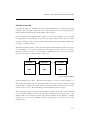
μC/TCP-IP is a compact, reliable, high-performance TCP/IP protocol stack. Built from the
ground up with Micrium’s unique combination of quality, scalability and reliability,
μC/TCP-IP, the result of many man-years of development, enables the rapid configuration of
required network options to minimize time to market.
The source code for μC/TCP-IP contains over 100,000 lines of the cleanest, most consistent
ANSI C source code available in a TCP/IP stack implementation. C was chosen since C is the
predominant language in the embedded industry. Over 50% of the code consists of
comments and most global variables and all functions are described. References to RFC
(Request For Comments) are included in the code where applicable.
1-1 PORTABLE
μC/TCP-IP is ideal for resource-constrained embedded applications. The code was designed
for use with nearly any CPU, RTOS, and network device. Although μC/TCP-IP can work on
some 8 and 16-bit processors, μC/TCP-IP is optimized for use with 32 or 64-bit CPUs.
1-2 SCALABLE
The memory footprint of μC/TCP-IP can be adjusted at compile time depending on the
features required, and the desired level of run-time argument checking appropriate for the
design at hand. SinceμC/TCP-IP is rich in its ability to provide statistics computation,
unnecessary statistics computation can be disabled to further reduce the footprint.
21
Coding Standards
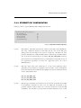
1-3 CODING STANDARDS
Coding standards were established early in the design of μC/TCP-IP. They include:
■
C coding style
■
Naming convention for #define constants, macros, variables and functions
■
Commenting
■
Directory structure
These conventions make μC/TCP-IP the preferred TCP/IP stack implementation in the
industry, and result in the ability to attain third party certification more easily as outlined in
the next section.
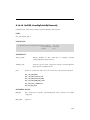
1-4 MISRA C
The source code for μC/TCP-IP follows Motor Industry Software Reliability Association
(MISRA) C Coding Standards. These standards were created by MISRA to improve the
reliability and predictability of C programs in safety-critical automotive systems. Members of
the MISRA consortium include such companies as Delco Electronics, Ford Motor Company,
Jaguar Cars Ltd., Lotus Engineering, Lucas Electronics, Rolls-Royce, Rover Group Ltd., and
universities dedicated to improving safety and reliability in automotive electronics. Full
details of this standard can be obtained directly from the MISRA web site at:
www.misra.org.uk.
1-5 SAFETY CRITICAL CERTIFICATION
μC/TCP-IP was designed from the ground up to be certifiable for use in avionics, medical
devices, and other safety-critical products. Validated Software’s Validation Suite™ for
μC/TCP-IP will provide all of the documentation required to deliver μC/TCP-IP as a
pre-certifiable software component for avionics RTCA DO-178B and EUROCAE ED-12B,
medical FDA 510(k), IEC 61508 industrial control systems, and EN-50128 rail transportation
and nuclear systems. The Validation Suite, available through Validated Software, will be
22
RTOS
immediately certifiable for DO-178B Level A, Class III medical devices, and SIL3/SIL4
IEC-certified systems. For more information, check out the μC/TCP-IP page on the Validated
Software web site at: www.ValidatedSoftware.com.
If your product is not safety critical, however, the presence of certification should be
viewed as proof that μC/TCP-IP is very robust and highly reliable.
1-6 RTOS
μC/TCP-IP assumes the presence of an RTOS, yet there are no assumptions as to which
RTOS to use with μC/TCP-IP. The only requirements are that it must:
■
Be able to support multiple tasks
■
Provide binary and counting semaphore management services
■
Provide message queue services
μC/TCP-IP contains an encapsulation layer that allows for the use of almost any commercial
or open source RTOS. Details regarding the RTOS are hidden from μC/TCP-IP. μC/TCP-IP
includes the encapsulation layer for μC/OS-II and μC/OS-III real-time kernels.
1-7 NETWORK DEVICES
μC/TCP-IP may be configured with multiple-network devices and network (IP) addresses.
Any device may be used as long as a driver with appropriate API and BSP software is
provided. The API for a specific device (i.e., chip) is encapsulated in a couple of files and it
is quite easy to adapt devices to μC/TCP-IP (see Chapter 12, “Statistics and Error Counters”
on page 298).
Although Ethernet devices are supported today, Micrium is currently working on adding
Point-to-Point Protocol (PPP) support to μC/TCP-IP.
23
μC/TCP-IP Protocols
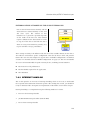
1-8 μC/TCP-IP PROTOCOLS
μC/TCP-IP consists of the following protocols:
■
Device drivers
■
Network interfaces (e.g., Ethernet, PPP (TBA), etc.)
■
Address Resolution Protocol (ARP)
■
Internet Protocol (IP)
■
Internet Control Message Protocol (ICMP)
■
Internet Group Management Protocol (IGMP)
■
User Datagram Protocol (UDP)
■
Transport Control Protocol (TCP)
■
Sockets (Micrium and BSD v4)
1-9 APPLICATION PROTOCOLS
Micrium offers application layer protocols as add-ons to μC/TCP-IP. A list of these network
services and applications includes:
■
μC/DCHPc, DHCP Client
■
μC/DNSc, DNS Client
■
μC/HTTPs, HTTP Server (web server)
■
μC/TFTPc, TFTP Client
■
μC/TFTPs, TFTP Server
24
Application Protocols
■
μC/FTPc, FTP Client
■
μC/FTPs, FTP Server
■
μC/SMTPc, SMTP Client
■
μC/POP3, POP3 Client
■
μC/SNTPc, Network Time Protocol Client
Any well known application layer protocols following the BSD socket API standard can be
used with μC/TCP-IP.
25
Chapter
2
μC/TCP-IP Architecture
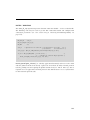
μC/TCP-IP was written to be modular and easy to adapt to a variety of Central Processing
Units (CPUs), Real-Time Operating Systems (RTOSs), network devices, and compilers.
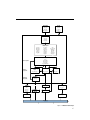
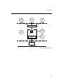
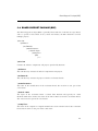
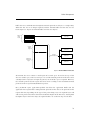
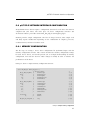
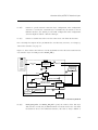
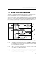
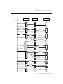
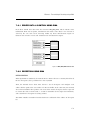
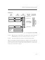
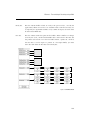
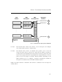
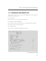
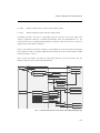
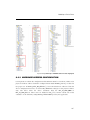
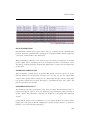
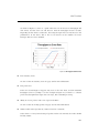
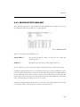
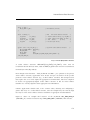
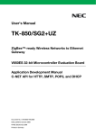
Figure 2-1 shows a simplified block diagram of μC/TCP-IP modules and their relationships.
Notice that all μC/TCP-IP files start with ‘net_’. This convention allows us to quickly identify
which files belong to μC/TCP-IP. Also note that all functions and global variables start with
‘Net’, and all macros and #defines start with ‘net_’.
26
Application
μC/LIB
app_cfg.h
net_cfg.h
net_dev_cfg.*
lib_def.h
lib_mem.*
lib_mem_a.*
lib_math.*
Socket API Layer
net_app.*
net_bsd.*
net_sock.*
TCP/IP Layers
net_arp.*
et_arp.*
net_icmp.*
net_icmp.*
net_igmp.*
net_igmp.*
net_ip.*
net_ip.*
net_tcp.*
net_tcp.*
net_udp.*
net_udp.*
net_ascii.*
net_ascii.*
net_buf.*
net_buf.*
net_conn.*
net_conn.*
net_ctr.*
net_ctr.*
net_stat.*
net_stat.*
net_tmr.*
net_tmr.*
net_util.*
net_util.*
net.*
net.*
net_cfg_net.h
net_cfg_net.h
net_dbg.*
net_dbg.*
net_def.h
net_def.h
net_err.*
net_err.*
net_type.h
net_type.h
net_mgr.*
net_mgr.*
IF Layer
net_if.*
net_if_802x.*
net_if_ether.*
net_if_wifi.*
net_if_loopback.*
Interface Specific
Device/
Chip Specific
Hardware/
CPU Specific
Wireless Manager
Layer
Device Layer
PHY Layer
net_wifi_mgr.*
net_dev_???.*
net_phy.*
BSP Layer
net_bsp.*
SPI
μC/CPU
cpu.*
cpu_def.*
cpu_core.*
cpu_a.*
MAC
RTOS Layer
net_os.*
Wireless
Module
PHY
RTOS
CPU
Network
Network
Figure 2-1 Module Relationships
27
μC/TCP-IP Module Relationships
2-1 μC/TCP-IP MODULE RELATIONSHIPS
2-1-1 APPLICATION
An application provides configuration information to μC/TCP-IP in the form of four C files:
app_cfg.h, net_cfg.h, net_dev_cfg.c and net_dev_cfg.h.
app_cfg.h is an application-specific configuration file that must be present in the
application. app_cfg.h contains #defines to specify the task priorities of each of the tasks
within the application (including those of μC/TCP-IP), and the stack size for those tasks.
Task priorities are placed in a file to make it easier to “see” task priorities for the entire
application in one place.
Configuration data in net_cfg.h consists of specifying the number of timers to allocate to
the stack, whether or not statistic counters will be maintained, the number of ARP cache
entries, how UDP checksums are computed, and more. One of the most important
configurations necessary is the size of the TCP Receive Window. In all, there are
approximately 50 #define to set. However, most of the #define constants can be set to
their recommended default value.
Finally, net_dev_cfg.c consists of device-specific configuration requirements such as the
number of buffers allocated to a device, the MAC address for that device, and necessary
physical layer device configuration including physical layer device bus address and link
characteristics. Each μC/TCP-IP-compatible device requires that its configuration be
specified within net_dev_cfg.c.
2-1-2 μC/LIB LIBRARIES
Given that μC/TCP-IP is designed for use in safety critical applications, all “standard” library
functions such as strcpy(), memset(), etc. have been rewritten to conform to the same
quality as the rest as the protocol stack.
28
μC/TCP-IP Module Relationships
2-1-3 BSD SOCKET API LAYER
The application interfaces to μC/TCP-IP uses the BSD socket Application Programming
Interface (API). The software developer can either write their own TCP/IP applications
using the BSD socket API or, purchase a number of off-the-shelf TCP/IP components
(Telnet, Web server, FTP server, etc.),for use with the BSD socket interface. Note that the
BSD socket layer is shown as a separate module but is actually part of μC/TCP-IP.
Alternatively, the software developer can use μC/TCP-IP’s own socket interface functions
(net_sock.*). net_bsd.* is a layer of software that converts BSD socket calls to μC/TCP-IP
socket calls. Of course, a slight performance gain is achieved by interfacing directly to
net_sock.* functions. Micrium network products use μC/TCP-IP socket interface functions.
2-1-4 TCP/IP LAYER
The TCP/IP layer contains most of the CPU, RTOS and compiler-independent code for
μC/TCP-IP. There are three categories of files in this section:
1
TCP/IP protocol specific files include:
ARP (net_arp.*),
ICMP (net_icmp.*),
IGMP (net_igmp.*),
IP (net_ip.*),
TCP (net_tcp.*),
UDP (net_udp.*)
2
Support files are:
ASCII conversions (net_ascii.*),
Buffer management (net_buf.*),
29
μC/TCP-IP Module Relationships
TCP/UDP connection management (net_conn.*),
Counter management (net_ctr.*),
Statistics (net_stat.*),
Timer Management (net_tmr.*),
Other utilities (net_util.*).
3
Miscellaneous header files include:
Master μC/TCP-IP header file (net.h)
File containing error codes (net_err.h)
Miscellaneous μC/TCP-IP data types (net_type.h)
Miscellaneous definitions (net_def.h)
Debug (net_dbg.h)
Configuration definitions (net_cfg_net.h)
2-1-5 NETWORK INTERFACE (IF) LAYER
The IF Layer involves several types of network interfaces (Ethernet, Token Ring, etc.).
However, the current version of μC/TCP-IP only supports Ethernet interfaces, wired and
wireless. The IF layer is split into two sub-layers.
net_if.* is the interface between higher Network Protocol Suite layers and the link layer
protocols. This layer also provides network device management routines to the application.
net_if_*.* contains the link layer protocol specifics independent of the actual device (i.e.,
hardware). In the case of Ethernet, net_if_ether.* understands Ethernet frames, MAC
addresses, frame de-multiplexing, and so on, but assumes nothing regarding actual Ethernet
hardware.
30
μC/TCP-IP Module Relationships
2-1-6 NETWORK DEVICE DRIVER LAYER
As previously stated, μC/TCP-IP works with just nearly any network device. This layer
handles the specifics of the hardware, e.g., how to initialize the device, how to enable and
disable interrupts from the device, how to find the size of a received packet, how to read a
packet out of the frame buffer, and how to write a packet to the device, etc.
In order for device drivers to have independent configuration for clock gating, interrupt controller,
and general purpose I/O, an additional file, net_bsp.c, encapsulates such details.
net_bsp.c contains code for the configuration of clock gating to the device, an internal or
external interrupt controller, necessary IO pins, as well as time delays, getting a time stamp
from the environment, and so on. This file is assumed to reside in the user application.
2-1-7 NETWORK PHYSICAL (PHY) LAYER
Often, devices interface to external physical layer devices, which may need to be initialized
and controlled. This layer is shown in Figure 2-1 asa “dotted” area indicating that it is not
present with all devices. In fact, some devices have PHY control built-in. Micrium provides
a generic PHY driver which controls most external (R)MII compliant Ethernet physical layer
devices.
2-1-8 NETWORK WIRELESS MANAGER
Often, wireless device may need to initialize a command and wait to receive the result (i.e.
Scan). This layer manages specific wireless management commands. Micrium provides a
generic Wireless Manager which should be able to controls most wireless module.
2-1-9 CPU LAYER
μC/TCP-IP can work with either an 8, 16, 32 or even 64-bit CPU, but it must have
information about the CPU used. The CPU layer defines such information as the C data type
corresponding to 16-bit and 32-bit variables, whether the CPU is little or big endian, and
how interrupts are disabled and enabled on the CPU.
CPU-specific files are found in the ...\uC-CPU directory and are used to adapt μC/TCP-IP
to a different CPU, modify either the cpu*.* files or, create new ones based on the ones
supplied in the uC-CPU directory. In general, it is much easier to modify existing files.
31
μC/TCP-IP Module Relationships
2-1-10 REAL-TIME OPERATING SYSTEM (RTOS) LAYER
μC/TCP-IP assumes the presence of an RTOS, but the RTOS layer allows μC/TCP-IP to be
independent of a specific RTOS. μC/TCP-IP consists of three tasks. One task is responsible
for handling packet reception, another task for asynchronous transmit buffer de-allocation,
and the last task for managing timers. Depending on the configuration, a fourth task may be
present to handle loopback operation.
As a minimum, the RTOS:
1
Must be able to create at least three tasks (a Receive task, a Transmit De-allocation task,
and a Timer task)
2
Provide semaphore management (or the equivalent) and the μC/TCP-IP needs to be
able to create at least two semaphores for each socket and an additional four
semaphores for internal use.
3
Provides timer management services
4
Port must also include support for pending on multiple OS objects if BSD socket
select() is required.
μC/TCP-IP is provided with a μC/OS-II and μC/OS-III interface. If a different RTOS is used,
the net_os.* for μC/OS-II or μC/OS-III can be used as templates to interface to the RTOS
chosen.
32
Task Model
2-2 TASK MODEL
The user application interfaces to μC/TCP-IP via a well known API called BSD sockets (or
μC/TCP-IP’s internal socket interface). The application can send and receive data to/from
other hosts on the network via this interface.
The BSD socket API interfaces to internal structures and variables (i.e., data) that are
maintained by μC/TCP-IP. A binary semaphore (the global lock in Figure 2-2) is used to
guard access to this data to ensure exclusive access. In order to read or write to this data, a
task needs to acquire the binary semaphore before it can access the data and release it
when finished. Of course, the application tasks do not have to know anything about this
semaphore nor the data since its use is encapsulated by functions within μC/TCP-IP.
Figure 2-2 shows a simplified task model of μC/TCP-IP along with application tasks.
2-2-1 μC/TCP-IP TASKS AND PRIORITIES
μC/TCP-IP defines three internal tasks: a Receive task, a Transmit De-allocation task, and a
Timer task. The Receive task is responsible for processing received packets from all devices.
The Transmit De-allocation task frees transmit buffer resources when they are no longer
required. The Timer task is responsible for handling all timeouts related to TCP/IP protocols
and network interface management.
When setting up task priorities, we generally recommend that tasks that use μC/TCP-IP’s
services be configured with higher priorities than μC/TCP-IP’s internal tasks. However,
application tasks that use μC/TCP-IP should voluntarily relinquish the CPU on a regular
basis. For example, they can delay or suspend the tasks or wait on μC/TCP-IP services. This
is to reduce starvation issues when an application task sends a substantial amount of data.
We recommend that you configure the network interface Transmit De-allocation task with a
higher priority than all application tasks that use μC/TCP-IP network services; but configure
the Timer task and network interface Receive task with lower priorities than almost other
application tasks.
See also section D-20-1 “Operating System Configuration” on page 770.
33
Task Model
App
Task
App
Task
App
Task
BSD Sockets API
Tx
De-allocation
Timer
Task
Task
Global Lock
µC/TCP-IP
Rx
Task
Dev
Network
Figure 2-2 μC/TCP-IP Task model
34
Task Model
2-2-2 RECEIVING A PACKET
Figure 2-3 shows a simplified task model of μC/TCP-IP when packets are received from the
device.
Sockets
TCP
IP
IF
(7)
(6)
µC/TCP-IP
Data
Rx
Task
(5)
(3)
Rx Queue
(8)
(4)
(2)
Global
Lock
(6)
Rx ISR
(1)
Device
Network
Figure 2-3 μC/TCP-IP Receiving a Packet
F2-3(1)
A packet is sent on the network and the device recognizes its address as the
destination for the packet. The device then generates an interrupt and the BSP
global ISR handler is called for non-vectored interrupt controllers. Either the global
ISR handler or the vectored interrupt controller calls the Net BSP device specific
35
Task Model
ISR handler, which in turn indirectly calls the device ISR handler using a predefined
Net IF function call. The device ISR handler determines that the interrupt comes
from a packet reception (as opposed to the completion of a transmission).
F2-3(2)
Instead of processing the received packet directly from the ISR, it
to pass the responsibility to a task. The Rx ISR therefore simply
Receive task by posting the interface number to the Receive task
that further Rx interrupts are generally disabled while processing
within the device ISR handler.
was decided
“signals” the
queue. Note
the interrupt
F2-3(3)
The Receive task does nothing until a signal is received from the Rx ISR.
F2-3(4)
When a signal is received from an Ethernet device, the Receive task wakes up
and extracts the packet from the hardware and places it in a receive buffer. For
DMA based devices, the receive descriptor buffer pointer is updated to point to
a new data area and the pointer to the receive packet is passed to higher layers
for processing.
μC/TCP-IP maintains three types of device buffers: small transmit, large
transmit, and large receive. For a common Ethernet configuration, a small
transmit buffer typically holds up to 256 bytes of data, a large transmit buffer
up to 1500 bytes of data, and a large receive buffer 1500 bytes of data. Note
that the large transmit buffer size is generally specified within the device
configuration as 1594 or 1614 bytes (see Chapter 9, “Buffer Management” on
page 277 for a precise definition). The additional space is used to hold
additional protocol header data. These sizes as well as the quantity of these
buffers are configurable for each interface during either compile time or run
time.
F2-3(5)
Buffers are shared resources and any access to those or any other μC/TCP-IP
data structures is guarded by the binary semaphore that guards the data. This
means that the Receive task will need to acquire the semaphore before it can
receive a buffer from the pool.
36
Task Model
F2-3(6)
The Receive task gets a buffer from the buffer pool. The packet is removed
from the device and placed in the buffer for further processing. For DMA, the
acquired buffer pointer replaces the descriptor buffer pointer that received the
current frame. The pointer to the received frame is passed to higher layers for
further processing.
F2-3(7)
The Receive task examines received data via the appropriate link layer protocol
and determines whether the packet is destined for the ARP or IP layer, and
passes the buffer to the appropriate layer for further processing. Note that the
Receive task brings the data all the way up to the application layer and
therefore the appropriate μC/TCP-IP functions operate within the context of the
Receive task.
F2-3(8)
When the packet is processed, the lock is released and the Receive task waits
for the next packet to be received.
37
Task Model
2-2-3 TRANSMITTING A PACKET
Figure 2-4 shows a simplified task model of μC/TCP-IP when packets are transmitted
through the device.
Application
Task
(1)
µC/TCP-IP
Data
Sockets
(2)
TCP
(3)
(6)
Global
Lock
(10)
IP
(11)
(4)
IF
Application
Task
(9)
(5)
Tx
De-allocation
Task Queue
Tx Ready
Semaphore
(8)
Tx ISR
(7)
Device
Network
Note: There is one Tx Ready
semaphore per device
Figure 2-4 μC/TCP-IP Sending a Packet
38
Task Model
F2-4(1)
A task (assuming an application task) that wants to send data interfaces to
μC/TCP-IP through the BSD socket API.
F2-4(2)
A function within μC/TCP-IP acquires the binary semaphore (i.e., the global
lock) in order to place the data to send into μC/TCP-IP’s data structures.
F2-4(3)
The appropriate μC/TCP-IP layer processes the data, preparing it for
transmission.
F2-4(4)
The task (via the IF layer) then waits on a counting semaphore, which is used
to indicate that the transmitter in the device is available to send a packet. If the
device is not able to send the packet, the task blocks until the semaphore is
signaled by the device. Note that during device initialization, the semaphore is
initialized with a value corresponding to the number of packets that can be
sent at one time through the device. If the device has sufficient buffer space to
be able to queue up four packets, then the counting semaphore is initialized
with a count of 4. For DMA-based devices, the value of the semaphore is
initialized to the number of available transmit descriptors.
F2-4(5)
When the device is ready, the driver either copies the data to the device
internal memory space or configures the DMA transmit descriptor. When the
device is fully configured, the device driver issues a transmit command.
F2-4(6)
After placing the packet into the device, the task releases the global data lock
and continues execution.
F2-4(7)
When the device finishes sending the data, the device generates an interrupt.
F2-4(8)
The Tx ISR signals the Tx Available semaphore indicating that the device is able
to send another packet. Additionally, the Tx ISR handler passes the address of
the buffer that completed transmission to the Transmit De-allocation task via a
queue which is encapsulated by an OS port function call.
F2-4(9)
The Transmit De-allocation task wakes up when a device driver posts a
transmit buffer address to its queue.
39
Task Model
F2-4(10)
The global data lock is acquired. If the global data lock is held by another task,
the Transmit De-allocation task must wait to acquire the global data lock. Since
it is recommended that the Transmit De-allocation task be configured as the
highest priority μC/TCP-IP task, it will run following the release of the global
data lock, assuming the queue has at least one entry present.
F2-4(11)
The lock is released when transmit buffer de-allocation is finished. Further
transmission and reception of additional data by application and μC/TCP-IP
tasks may resume.
40
Chapter
3
Directories and Files
This chapter will discuss the modules available for μC/TCP-IP, and how they all fit together.
A Windows®-based development platform is assumed. The directories and files make
references to typical Windows-type directory structures. However, since μC/TCP-IP is
available in source form, it can also be used with any ANSI-C compatible compiler/linker
and any Operating System.
The names of the files are shown in upper case to make them stand out. However, file
names are actually lower case.
41
Block Diagram
3-1 BLOCK DIAGRAM
Figure 3-1 is a block diagram of the modules found in μC/TCP-IP and their relationship.
Also included are the names of the files that are related to μC/TCP-IP.
Application
app_cfg.h
net_cfg.h
net_dev_cfg.*
Sockets
Sockets
net_app.*
net_bsd.*
net_sock.*
net_app.*
net_bsd.*
net_sock.*
TCP
UDP
ICMP
IGMP
IGMP
ICMP
UDP
TCP
net_tcp.*
net_udp.*
net_icmp.*
net_igmp.*
net_igmp.*
net_icmp.*
net_udp.*
net_tcp.*
Buf
IP
IP
net_ip.*
net_ip.*
net_buf.*
Tmr
net_tmr.*
RX
Misc
ARP
ARP
net_arp.*
net_arp.*
μC/CPU
TX
IF
IF
net_if.*
net_if.*
cpu*.*
cpu_def.h
μC/LIB
lib_def.h
lib_mem.*
lib_str.*
lib_math.*
net.*
net_ascii.*
net_cfg_net.h
net_conn.*
net_ctr.*
net_dbg.*
net_def.*
net_err.*
net_stat.*
net_type.*
net_util.*
IF Specific
net_if_ether.*
net_if_wifi.*
net_if_loopback.*
IF Specific
IF 802x
IF 802x
net_if_802x.*
net_if_802x.*
net_if_ether.*
net_if_wifi.*
net_if_loopback.*
Dev
BSP
Dev
net_dev_???.*
net_bsp.*
net_dev_???.*
Hardware
Network
Network
Figure 3-1 μC/TCP-IP Block Diagram
42
Application Code
3-2 APPLICATION CODE
When Micrium provides example projects, they are placed in a directory structure shown
below. Of course, a directory structure that suits a particular project/product can be used.
\Micrium
\Software
\EvalBoards
\<manufacturer>
\<board_name>
\<compiler>
\<project name>
\*.*
\Micrium
This is where we place all software components and projects provided by Micrium. This
directory generally starts from the root directory of the computer.
\Software
This sub-directory contains all software components and projects.
\EvalBoards
This sub-directory contains all projects related to evaluation boards supported by Micrium.
\<manufacturer>
This is the name of the manufacturer of the evaluation board. The ‘<’ and ‘>’ are not part of
the actual name.
\<board name>
This is the name of the evaluation board. A board from Micrium will typically be called
uC-Eval-xxxx where xxxx represents the CPU or MCU used on the board. The ‘<’ and ‘>’
are not part of the actual name.
\<compiler>
This is the name of the compiler or compiler manufacturer used to build the code for the
evaluation board. The ‘<’ and ‘>’ are not part of the actual name.
43
Application Code
\<project name>
The name of the project that will be demonstrated. For example a simple μC/TCP-IP project
might have a project name of ‘OS-Ex1’. The ‘-Ex1’ represents a project containing only
μC/OS-III. A project name of OS-Probe-Ex1 contains μC/TCP-IP and μC/Probe. The ‘<’ and
‘>’ are not part of the actual name.
\*.*
These are the source files for the project. Main files can optionally be called APP*.*. This
directory also contains configuration files app_cfg.h, net_cfg.h, net_decv_cfg.h,
net_dev_cfg.c,os_cfg.h, os_cfg_app.h and other project-required source files.
includes.h is the application-specific master include header file. Almost all Micrium
products require this file.
net_cfg.h is a configuration file used to configure such μC/TCP-IP parameters as the
number of network timers, sockets, and connections created; default timeout values,
and more. net_cfg.h must be included in the application as μC/TCP-IP requires this
file. See Chapter 16, “Network Interface Layer” on page 361 for more information.
net_dev_cfg.c and net_dev_cfg.h are configuration files used to configure
μC/TCP-IP interface parameters such as the number of transmit and receive buffers. See
Chapter 5, “Network Interface Configuration” on page 77 for more details.
os_cfg.h is a configuration file used to configure μC/OS-III parameters such as the
maximum number of tasks, events, and objects; which μOS-III services are enabled
(semaphores, mailboxes, queues); etc. os_cfg.his a required file for any μC/OS-III
application. See μC/OS-III documentation and books for further information.
app.c contains the application code for the Processor example project. As with most C
programs, code execution starts at main() which is shown in Listing 4-1 on page 69.
The application code starts μC/TCP-IP.
44
CPU
3-3 CPU
The directory shown below contains semiconductor manufacturer peripheral interface
source files. Any directory structure that suits the project/product may be used.
\Micrium
\Software
\CPU
\<manufacturer>
\<architecture>
\*.*
\Micrium
The location of all software components and projects provided by Micrium.
\Software
This sub-directory contains all software components and projects.
\CPU
This sub-directory is always called CPU.
\<manufacturer>
Is the name of the semiconductor manufacturer providing the peripheral library. The
< and > are not part of the actual name.
\<architecture>
The name of the specific library, generally associated with a CPU name or an architecture.
\*.*
Indicates library source files. The semiconductor manufacturer names the files.
45
Board Support Package (BSP)
3-4 BOARD SUPPORT PACKAGE (BSP)
The Board Support Package (BSP) is generally found with the evaluation or target board,
and it is specific to that board. In fact, when well written, the BSP should be used for
multiple projects.
\Micrium
\Software
\EvalBoards
\<manufacturer>
\<board name>
\<compiler>
\BSP
\*.*
\Micrium
Contains all software components and projects provided by Micrium.
\Software
This sub-directory contains all software components and projects.
\EvalBoards
This sub-directory contains all projects related to evaluation boards.
\<manufacturer>
The name of the manufacturer of the evaluation board. The < and > are not part of the
actual name.
\<board name>
The name of the evaluation board. A board from Micrium will typically be called
uC-Eval-xxxx where xxxx is the name of the CPU or MCU used on the evaluation board.
The < and > are not part of the actual name.
\<compiler>
The name of the compiler or compiler manufacturer used to build code for the evaluation
board. The < and > are not part of the actual name.
46
Network Board Support Package (NET_BSP)
\BSP
This directory is always called BSP.
\*.*
The source files of the BSP. Typically all of the file names start with BSP. It is therefore
normal to find bsp.c and bsp.h in this directory. BSP code should contain such functions
as LED control functions, initialization of timers, interface to Ethernet controllers, and more.
BSP stands for Board Support Package and the 'services' the board provides are placed in
such a file. In this case, bsp.c contains I/O, timer initialization code, LED control code, and
more. The I/Os used on the board are initialized when BSP_Init() is called.
The concept of a BSP is to hide the hardware details from the application code. It is
important that functions in a BSP reflect the function and do not make references to any
CPU specifics. For example, the code to turn on an LED is called LED_On() and not
MCU_led(). If LED_On() is used in the code, it can be easily ported to another processor (or
board) by simply rewriting LED_On() to control the LEDs on a different board. The same is
true for other services. Also notice that BSP functions are prefixed with the function’s group.
LED services start with LED_, timer services start with Tmr_, etc. In other words, BSP
functions do not need to be prefixed by BSP_.
3-5 NETWORK BOARD SUPPORT PACKAGE (NET_BSP)
In addition to the general (BSP) there are specific network initialization and configuration
requirements. This additional file is generally found with the evaluation or target board as it
is specific to that board.
\Micrium
\Software
\EvalBoards
\<manufacturer>
\<board name>
\<compiler>
\BSP
\TCPIP-V2
\*.*
47
Network Board Support Package (NET_BSP)
\Micrium
Contains all software components and projects provided by Micrium.
\Software
This sub-directory contains all software components and projects.
\EvalBoards
This sub-directory contains all projects related to evaluation boards.
\<manufacturer>
The name of the manufacturer of the evaluation board. The ‘<’ and ‘>’ are not part of the
actual name.
\<board name>
The name of the evaluation board. A board from Micrium will typically be called
uC-Eval-xxxx where xxxx is the name of the CPU or MCU used on the evaluation board.
The ‘<’ and ‘>’ are not part of the actual name.
\<compiler>
The name of the compiler or compiler manufacturer used to build code for the evaluation
board. The ‘<’ and ‘>’ are not part of the actual name.
\BSP
This directory is always called BSP.
\TCPIP-V2
This directory is always called TCPIP-V2 as it is the directory for the network related BSP
files.
\*.*
The net_bsp.* files contain hardware-dependent code specific to the network device(s)
and other μC/TCP-IP functions. Specifically, these files may contain code to read data from
and write data to network devices, handle hardware-level device interrupts, provide delay
functions, and get time stamps, etc.
48
μC/OS-III, CPU Independent Source Code
3-6 μC/OS-III, CPU INDEPENDENT SOURCE CODE
The files in these directories are available to μC/OS-III licensees (see Appendix X,
“Licensing Policy”).
\Micrium
\Software
\uCOS-III
\Cfg\Template
\Source
\Micrium
Contains all software components and projects provided by Micrium.
\Software
This sub-directory contains all software components and projects.
\uCOS-III
This is the main μC/OS-III directory.
\Cfg\Template
This directory contains examples of configuration files to copy to the project directory.
These files can be modified to suit the needs of the application.
\Source
The directory contains the CPU-independent source code for μC/OS-III. All files in this
directory should be included in the build (assuming the presence of the source code).
Features that are not required will be compiled out based on the value of #define constants
in os_cfg.h and os_cfg_app.h.
49
μC/OS-III, CPU Specific Source Code
3-7 μC/OS-III, CPU SPECIFIC SOURCE CODE
The μC/OS-III port developer provides these files. See Chapter 17 in the μC/OS-III book.
\Micrium
\Software
\uCOS-III
\Ports
\<architecture>
\<compiler>
\Micrium
Contains all software components and projects provided by Micrium.
\Software
This sub-directory contains all software components and projects.
\uCOS-III
The main μC/OS-III directory.
\Ports
The location of port files for the CPU architecture(s) to be used.
\<architecture>
This is the name of the CPU architecture that μC/OS-III was ported to. The ‘<’ and ‘>’ are
not part of the actual name.
\<compiler>
The name of the compiler or compiler manufacturer used to build code for the port. The
< and > are not part of the actual name.
The files in this directory contain the μC/OS-III port, see Chapter 17 “Porting μC/OS-III” in
the μC/OS-III book for details on the contents of these files.
50
μC/CPU, CPU Specific Source Code
3-8 μC/CPU, CPU SPECIFIC SOURCE CODE
μC/CPU consists of files that encapsulate common CPU-specific functionality and CPU and
compiler-specific data types.
\Micrium
\Software
\uC-CPU
\cpu_core.c
\cpu_core.h
\cpu_def.h
\Cfg\Template
\cpu_cfg.h
\<architecture>
\<compiler>
\cpu.h
\cpu_a.asm
\cpu_c.c
\Micrium
Contains all software components and projects provided by Micrium.
\Software
This sub-directory contains all software components and projects.
\uC-CPU
This is the main μC/CPU directory.
cpu_core.c contains C code that is common to all CPU architectures. Specifically, this
file contains functions to measure the interrupt disable time of the
CPU_CRITICAL_ENTER() and CPU_CRITICAL_EXIT() macros, a function that emulates a
count leading zeros instruction and a few other functions.
cpu_core.h contains function prototypes for the functions provided in cpu_core.c
and allocation of the variables used by the module to measure interrupt disable time.
cpu_def.h contains miscellaneous #define constants used by the μC/CPU module.
51
μC/CPU, CPU Specific Source Code
\Cfg\Template
This directory contains a configuration template file (cpu_cfg.h) that is required to be
copied to the application directory to configure the μC/CPU module based on application
requirements.
cpu_cfg.h determines whether to enable measurement of the interrupt disable time,
whether the CPU implements a count leading zeros instruction in assembly language, or
whether it will be emulated in C, and more.
\<architecture>
The name of the CPU architecture that μC/CPU was ported to. The ‘<’ and ‘>’ are not part of
the actual name.
\<compiler>
The name of the compiler or compiler manufacturer used to build code for the μC/CPU
port. The ‘<’ and ‘>’ are not part of the actual name.
The files in this directory contain the μC/CPU port, see Chapter 17 of the μC/OS-III book,
“Porting μC/OS-III” for details on the contents of these files.
cpu.h contains type definitions to make μC/OS-III and other modules independent of
the CPU and compiler word sizes. Specifically, one will find the declaration of the
CPU_INT16U, CPU_INT32U, CPU_FP32 and many other data types. This file also specifies
whether the CPU is a big or little endian machine, defines the CPU_STK data type used
by μC/OS-III, defines the macros OS_CRITICAL_ENTER() and OS_CRITICAL_EXIT(),
and contains function prototypes for functions specific to the CPU architecture, etc.
cpu_a.asm contains the assembly language functions to implement code to disable and
enable CPU interrupts, count leading zeros (if the CPU supports that instruction), and
other CPU specific functions that can only be written in assembly language. This file
may also contain code to enable caches, and setup MPUs and MMU. The functions
provided in this file are accessible from C.
cpu_c.c contains the C code of functions that are based on a specific CPU architecture
but written in C for portability. As a general rule, if a function can be written in C then
it should be, unless there is significant performance benefits available by writing it in
assembly language.
52
μC/LIB, Portable Library Functions
3-9 μC/LIB, PORTABLE LIBRARY FUNCTIONS
μC/LIB consists of library functions meant to be highly portable and not tied to any specific
compiler. This facilitates third-party certification of Micrium products. μC/OS-III does not
use any μC/LIB functions, however the μC/CPU assumes the presence of lib_def.h for
such definitions as: DEF_YES, DEF_NO, DEF_TRUE, DEF_FALSE, etc.
\Micrium
\Software
\uC-LIB
\lib_ascii.c
\lib_ascii.h
\lib_def.h
\lib_math.c
\lib_math.h
\lib_mem.c
\lib_mem.h
\lib_str.c
\lib_str.h
\Cfg\Template
\lib_cfg.h
\Ports
\<architecture>
\<compiler>
\lib_mem_a.asm
\Micrium
Contains all software components and projects provided by Micrium.
\Software
This sub-directory contains all software components and projects.
\uC-LIB
This is the main μC/LIB directory.
53
μC/TCP-IP Network Devices
\Cfg\Template
This directory contains a configuration template file (lib_cfg.h) that is required to be
copied to the application directory to configure the μC/LIB module based on application
requirements.
lib_cfg.h determines whether to enable assembly language optimization (assuming
there is an assembly language file for the processor, i.e., lib_mem_a.asm) and a few
other #defines.
3-10 μC/TCP-IP NETWORK DEVICES
The files in these directories are
\Micrium
\Software
\uC-TCPIP-V2
\Dev
\Ether
\PHY
\Generic
\<Controller>
\WiFi
\Manager
\Generic
\<Controller>
\Micrium
Contains all software components and projects provided by Micrium.
\Software
This sub-directory contains all software components and projects.
\uC-TCPIP-V2
This is the main directory for the μC/TCP-IP code. The name of the directory contains a
version number to differentiate it from previous versions of the stack.
54
μC/TCP-IP Network Devices
\Dev
This directory contains device drivers for different interfaces. Currently, μC/TCP-IP only
supports one type of interface, Ethernet. μC/TCP-IP is tested with many types of Ethernet
devices.
\Ether
Ethernet controller drivers are placed under the Ether sub-directory. Note that device drivers
must also be called net_dev_<controller>.*.
\WiFi
Wireless controller drivers are placed under the WiFi sub-directory. Note that device drivers
must also be called net_dev_<controller>.*.
\PHY
This is the main directory for Ethernet Physical layer drivers.
\Generic
This is the directory for the Micrium provided generic PHY driver. Micrium’s generic
Ethernet PHY driver provides sufficient support for most (R)MII compliant Ethernet physical
layer devices. A specific PHY driver may be developed in order to provide extended
functionality such as link state interrupt support.
net_phy.h is the network physical layer header file.
net_phy.c provides the (R)MII interface port that is assumed to be part of the host
Ethernet MAC. Therefore, (R)MII reads/writes must be performed through the network
device API interface via calls to function pointers Phy_RegRd() and Phy_RegWr().
\Manager
This is the main directory for Wireless Manager layer.
\Generic
This is the directory for the Micriμm provided generic Wireless Manager layer. Micriμm's
generic Wireless Manager layer provides sufficient support for most wireless devices that
embed a wireless supplicant. A specific Wireless Manager may be developed in order to
provide extended functionality.
net_wifi_mgr.h is the network Wireless Manager layer header file.
55
μC/TCP-IP Network Interface
net_wifi_mgr.c provides functionality to access the device for management
command that could required asynchronous response such as scan for available
network.
\<controller>
The name of the Ethernet or wireless controller or chip manufacturer used in the project.
The ‘<’ and ‘>’ are not part of the actual name. This directory contains the network device
driver for the Network Controller specified.
net_dev_<controller>.h is the header file for the network device driver.
net_dev_<controller>.c contains C code for the network device driver API.
3-11 μC/TCP-IP NETWORK INTERFACE
This directory contains interface-specific files. Currently, μC/TCP-IP only supports three type
of interfaces, Ethernet, wireless and loopback. The Ethernet and wireless interface-specific
files are found in the following directories:
\Micrium
\Software
\uC-TCPIP-V2
\IF
\Micrium
Contains all software components and projects provided by Micrium.
\Software
This sub-directory contains all software components and projects.
\uC-TCPIP-V2
This is the main μC/TCP-IP directory.
\IF
This is the main directory for network interfaces.
56
μC/TCP-IP Network File System abstraction layer
net_if.* presents a programming interface between higher μC/TCP-IP layers and the
link layer protocols. These files also provide interface management routines to the
application.
net_if_802x.* contains common code to receive and transmit 802.3 and Ethernet
packets. This file should not need to be modified.
net_if_ether.* contains the Ethernet interface specifics. This file should not need to
be modified.
net_if_wifi.* contains the wireless interface specifics. This file should not need to be
modified.
net_if_loopback.* contains loopback interface specifics. This file should not need to
be modified.
3-12 μC/TCP-IP NETWORK FILE SYSTEM ABSTRACTION LAYER
This directory contains the file system abstraction layer which allows the TCP-IP application
such as μC/HTTPs, μC/FTPc, μC/FTPs, etc. with nearly any commercial or in-house file
system. The abstraction layer for the selected file system is placed in a sub-directory under
FS as follows:
\Micrium
\Software
\uC-TCPIP-V2
\FS
\<file_system_name>
\Micrium
Contains all software components and projects provided by Micrium.
\Software
This sub-directory contains all software components and projects.
\uC-TCPIP-V2
This is the main μC/TCP-IP directory.
57
μC/TCP-IP Network OS Abstraction Layer
\FS
This is the main FS directory that contain generic file system port header file. This file must
be included if one or more application that required a file system such as μC/HTTPs,
μC/FTPc, μC/FTPs, etc. are present in the project.
\<file_system_name>
This is the directory that contains the files to perform file system abstraction.
μC/TCP-IP has been tested with μC/FS-V4 and the file system layer files for this file system
are found in the following directories:
\Micrium\Software\uC-TCPIP-V2\FS\uC-FS-V4\net_fs_v4.*
3-13 μC/TCP-IP NETWORK OS ABSTRACTION LAYER
This directory contains the RTOS abstraction layer which allows the use of μC/TCP-IP with
nearly any commercial or in-house RTOS. The abstraction layer for the selected RTOS is
placed in a sub-directory under OS as follows:
\Micrium
\Software
\uC-TCPIP-V2
\OS
\<rtos_name>
\Micrium
Contains all software components and projects provided by Micrium.
\Software
This sub-directory contains all software components and projects.
\uC-TCPIP-V2
This is the main μC/TCP-IP directory.
\OS
This is the main OS directory.
58
μC/TCP-IP Network CPU Specific Code
\<rtos_name>
This is the directory that contains the files to perform RTOS abstraction. Note that files for
the selected RTOS abstraction layer must always be named net_os.*.
μC/TCP-IP has been tested with μC/OS-II, μC/OS-III and the RTOS layer files for these
RTOS are found in the following directories:
\Micrium\Software\uC-TCPIP-V2\OS\uCOS-II\net_os.*
\Micrium\Software\uC-TCPIP-V2\OS\uCOS-III\net_os.*
3-14 μC/TCP-IP NETWORK CPU SPECIFIC CODE
Some functions can be optimized in assembly to improve the performance of the network
protocol stack. An easy candidate is the checksum function. It is used at multiple levels in
the stack, and a checksum is generally coded as a long loop.
\Micrium
\Software
\uC-TCPIP-V2
\Ports
\<architecture>
\<compiler>
\net_util_a.asm
\Micrium
Contains all software components and projects provided by Micrium.
\Software
This sub-directory contains all software components and projects.
\uC-TCPIP-V2
This is the main μC/TCP-IP directory.
\Ports
This is the main directory for processor specific code.
59
μC/TCP-IP Network CPU Independent Source Code
\<architecture>
The name of the CPU architecture that was ported to. The ‘<’ and ‘>’ are not part of the
actual name.
\<compiler>
The name of the compiler or compiler manufacturer used to build code for the optimized
function(s). The ‘<’ and ‘>’ are not part of the actual name.
net_util_a.asm contains assembly code for the specific CPU architecture. All
functions that can be optimized for the CPU architecture are located here.
3-15 μC/TCP-IP NETWORK CPU INDEPENDENT SOURCE CODE
This directory contains all the CPU and RTOS independent files for μC/TCP-IP. Nothing
should be changed in this directory in order to use μC/TCP-IP.
\Micrium
\Software
\uC-TCPIP-V2
\Source
\Micrium
Contains all software components and projects provided by Micrium.
\Software
This sub-directory contains all software components and projects.
\uC-TCPIP-V2
This is the main μC/TCP-IP directory.
\Source
This is the directory that contains all the CPU and RTOS independent source code files.
60
μC/TCP-IP Network Security Manager CPU Independent Source Code
3-16 μC/TCP-IP NETWORK SECURITY MANAGER CPU
INDEPENDENT SOURCE CODE
This directory contains all the CPU independent files for μC/TCP-IP Network Security
Manager. Nothing should be changed in this directory in order to use μC/TCP-IP.
\Micrium
\Software
\uC-TCPIP-V2
\Secure
\<security_suite_name>
\Micrium
Contains all software components and projects provided by Micrium.
\Software
This sub-directory contains all software components and projects.
\uC-TCPIP-V2
This is the main μC/TCP-IP directory.
\Secure
This is the main Secure directory that contains the generic secure port header file. This file
should be included in the project only if a security suite is available and is to be used by the
application.
\Secure\<security_suite_name>
This is the directory that contains the files to perform security suite abstraction. These files
should only be included in the project if a security suite (i.e Mocana - NanoSSL) is available
and is to be used by the application.
61
Summary
3-17 SUMMARY
Below is a summary of all directories and files involved in a μC/TCP-IP-based project. The
‘<-Cfg’ on the far right indicates that these files are typically copied into the application
(i.e., project) directory and edited based on project requirements.
\Micrium
\Software
\EvalBoards
\<manufacturer>
\<board name>
\<compiler>
\<project name>
\app.c
\app.h
\other
\BSP
\bsp.c
\bsp.h
\others
\TCPIP-V2
\net_bsp.c
\net_bsp.h
\CPU
\<manufacturer>
\<architecture>
\*.*
\uCOS-III
\Cfg\Template
\os_app_hooks.c
\os_cfg.h
\os_cfg_app.h
\Source
\os_cfg_app.c
\os_core.c
\os_dbg.c
\os_flag.c
\os_int.c
<-Cfg
<-Cfg
62
Summary
\os_mem.c
\os_msg.c
\os_mutex.c
\os_pend_multi.c
\os_prio.c
\os_q.c
\os_sem.c
\os_stat.c
\os_task.c
\os_tick.c
\os_time.c
\os_tmr.c
\os_var.c
\os.h
\os_type.h
\Ports
\<architecture>
\<compiler>
\os_cpu.h
\os_cpu_a.asm
\os_cpu_c.c
\uC-CPU
\cpu_core.c
\cpu_core.h
\cpu_def.h
\Cfg\Template
\cpu_cfg.h
\<architecture>
\<compiler>
\cpu.h
\cpu_a.asm
\cpu_c.c
\uC-LIB
\lib_ascii.c
\lib_ascii.h
\lib_def.h
\lib_math.c
\lib_math.h
<-Cfg
<-Cfg
63
Summary
\lib_mem.c
\lib_mem.h
\lib_str.c
\lib_str.h
\Cfg\Template
\lib_cfg.h
\Ports
\<architecture>
\<compiler>
\lib_mem_a.asm
\uC-TCPIP-V2
\BSP
Template
\net_bsp.c
\net_bsp.h
OS
\<rtos_name>
\net_bsp.c
\CFG
\Template
\net_cfg.h
\net_dev_cfg.c
\net_dev_cfg.h
\Dev
\Ether
\<controller>
\net_dev_<controller>.c
\net_dev_<controller>.h
\PHY
\controller>
\net_phy_<controller>.c
\net_phy_<controller>.h
\Generic
\net_phy.c
\net_phy.h
\WiFi
\<controller>
\net_dev_<controller>.c
<-Cfg
<-Cfg
<-Cfg
<-Cfg
<-Cfg
<-Cfg
<-Cfg
64
Summary
\net_dev_<controller>.h
\Manager
\Generic
\net_wifi_mgr.c
\net_wifi_mgr.h
\IF
\net_if.c
\net_if.h
\net_if_802x.c
\net_if_802x.h
\net_if_ether.c
\net_if_ether.h
\net_if_wifi.c
\net_if_wifi.h
\net_if_loopback.c
\net_if_loopback.h
\OS
\<template>
\net_os.c
\net_os.h
\<rtos_name>
\net_os.c
\net_os.h
\Ports
\<architecture>
\<compiler>
\net_util_a.asm
\Secure
net_secure.h
\<security_suite_name>
\net_secure_<suite_name>.c
\net_secure_<suite_name>.h
\Source
\net.c
\net.h
\net_app.c
\net_app.h
\net_arp.c
<-Cfg
<-Cfg
65
Summary
\net_arp.h
\net_ascii.c
\net_ascii.h
\net.bsd.c
\net.bsd.h
\net.buf.c
\net.buf.h
\net.cfg_net.h
\net.conn.c
\net.conn.h
\net.ctr.c
\net.ctr.h
\net.dbg.c
\net.dbg.h
\net.def.h
\net.err.c
\net.err.h
\net.icmp.c
\net.icmp.h
\net.igmp.c
\net.igmp.h
\net.ip.c
\net.ip.h
\net.mgr.c
\net.mgr.h
\net.sock.c
\net.sock.h
\net.stat.c
\net.stat.h
\net.tcp.c
\net.tcp.h
\net.tmr.c
\net.tmr.h
\net.type.h
\net.udp.c
\net.udp.h
\net.util.c
\net.util.h
66
Chapter
4
Getting Started with μC/TCP-IP
As previously stated, the Directories and Files structure used herein assumes you have
access to the μC/TCP-IP source code. The samples and examples in Part II of this book,
however, use μC/TCP-IP as a library. The project structure is therefore different.
μC/TCP-IP requires an RTOS and, for the purposes of this book, μC/OS-III has been chosen.
First, because it is the latest kernel from Micrium, and second, because all the examples in
this book were developed with the evaluation board that is available with the μC/OS-III
book. This way there is no need for an additional evaluation board.
4-1 INSTALLING μC/TCP-IP
Distribution of μC/TCP-IP is performed through release files. The release archive files
contain all of the source code and documentation for μC/TCP-IP. Additional support files
such as those located within the CPU directory may or may not be required depending on
the target hardware and development tools. Example startup code, if available, may be
delivered upon request. Example code is located in the Evalboards directory when
applicable.
Figure 4-1 Directory tree for μC/TCP-IP
67
μC/TCP-IP Example Project
4-2 μC/TCP-IP EXAMPLE PROJECT
The following example project is used to show the basic architecture of μC/TCP-IP and to
build an empty application. The application also uses μC/OS-III as the RTOS. Figure 4-1
shows the project test setup. A Windows-based PC and the target system were connected to
a 100 Mbps Ethernet switch or via an Ethernet cross-over cable. The PC’s IP address is set to
10.10.10.111 and one of the target’s addresses is configured to 10.10.10.64.
7
%R DUJ
DU HW
G
3LQJ
(WKHUQHW6ZLWFK
RU&URVVRYHUFDEOH
Figure 4-2 Test setup
This example contains enough code to be able to ping the board.The IP address of the
board is forced to be 10.10.10.64. With a similar setup, the following command from a
command-prompt is issued:
ping 10.10.10.64
Ping (on the PC) should reply back with the ping time to the target. μC/TCP-IP target
projects connected to the test PC on the same Ethernet switch or Ethernet cross-over cable
achieve ping times of less than 2 milliseconds.
The next sections show the directory tree of different components required to build a
μC/TCP-IP example project.
68
Application Code
4-3 APPLICATION CODE
File app.c contains the application code for the Processor example project. As with most
C programs, code execution starts at main() which is shown in Listing 4-1. The application
code starts μC/TCP-IP.
void main (void)
{
OS_ERR err_os;
BSP_IntDisAll();
(1)
OSInit(&err_os);
APP_TEST_FAULT(err_os, OS_ERR_NONE);
(2)
OSTaskCreate((OS_TCB
*)&AppTaskStartTCB,
(CPU_CHAR
*)”App Task Start”,
(OS_TASK_PTR ) AppTaskStart,
(void
*) 0,
(OS_PRIO
) APP_OS_CFG_START_TASK_PRIO,
(CPU_STK
*)&AppTaskStartStk[0],
(3)
(4)
(5)
(6)
(7)
(8)
(CPU_STK_SIZE) APP_OS_CFG_START_TASK_STK_SIZE / 10u,
(CPU_STK_SIZE) APP_OS_CFG_START_TASK_STK_SIZE,
(OS_MSG_QTY ) 0u,
(OS_TICK
) 0u,
(void
*) 0,
(OS_OPT
) (OS_OPT_TASK_STK_CHK | OS_OPT_TASK_STK_CLR),
(OS_ERR
*)&err_os);
APP_TEST_FAULT(err_os, OS_ERR_NONE);
OSStart(&err_os);
APP_TEST_FAULT(err_os, OS_ERR_NONE);
(9)
(10)
(11)
(12)
(13)
}
Listing 4-1 Code execution starts at main()
L4-1(1)
Start main() by calling a BSP function that disables all interrupts. On most
processors, interrupts are disabled at startup until explicitly enabled by application
code. However, it is safer to turn off all peripheral interrupts during startup.
69
Application Code
L4-1(2)
Call OSInit(), which is responsible for initializing μC/OS-III internal variables
and data structures, and also creates two (2) to five (5) internal tasks. At minimum,
μC/OS-III creates the idle task (OS_IdleTask()), which executes when no other
task is ready to run. μC/OS-III also creates the tick task, responsible for
keeping track of time.
Depending on the value of #define constants, μC/OS-III will create the statistic
task (OS_StatTask()), the timer task (OS_TmrTask()), and interrupt handler
queue management task (OS_IntQTask()).
Most μC/OS-III’s functions return an error code via a pointer to an OS_ERR
variable, err in this case. If OSInit() was successful, err will be set to
OS_ERR_NONE. If OSInit() encounters a problem during initialization, it will
return immediately upon detecting the problem and set err accordingly. If this
occurs, look up the error code value in os.h. All error codes start with
OS_ERR_.
Note that OSInit() must be called before any other μC/OS-III function.
L4-1(3)
Create a task by calling OSTaskCreate(). OSTaskCreate() requires 13
arguments. The first argument is the address of the OS_TCB that is declared for
this task.
L4-1(4)
OSTaskCreate() allows a name to be assigned to each of the tasks. μC/OS-III
stores a pointer to the task name inside the OS_TCB of the task. There is no
limit on the number of ASCII characters used for the name.
L4-1(5)
The third argument is the address of the task code. A typical μC/OS-III task is
implemented as an infinite loop as shown:
void MyTask (void *p_arg)
{
/* Do something with ‘p_arg’.
while (1) {
/* Task body */
}
}
70
Application Code
The task receives an argument when at inception. The task resembles any
C function that can be called by code. However, the code must not
call MyTask().
L4-1(6)
The fourth argument of OSTaskCreate() is the argument that the task receives
when it first begins. In other words, the p_arg of MyTask(). In the example a
NULL pointer is passed, and thus p_arg for AppTaskStart() will be a NULL
pointer.
The argument passed to the task can actually be any pointer. For example, you
may pass a pointer to a data structure containing parameters for the task.
L4-1(7)
The next argument to OSTaskCreate() is the priority of the task. The priority
establishes the relative importance of this task with respect to other tasks in the
application. A low-priority number indicates a high priority (or more important
task). Set the priority of the task to any value between 1 and
OS_CFG_PRIO_MAX-2, inclusively. Avoid using priority #0, and priority
OS_CFG_PRIO_MAX-1, because these are reserved for μC/OS-III.
OS_CFG_PRIO_MAX is a compile time configuration constant, which is declared
in os_cfg.h.
L4-1(8)
The sixth argument to OSTaskCreate() is the base address of the stack
assigned to this task. The base address is always the lowest memory location of
the stack.
L4-1(9)
The next argument specifies the location of a “watermark” in the task’s stack
that can be used to determine the allowable stack growth of the task. In the
code above, the value represents the amount of stack space (in CPU_STK
elements) before the stack is empty. In other words, in the example, the limit is
reached when 10% of the stack is left.
L4-1(10)
The eighth argument to OSTaskCreate() specifies the size of the task’s stack in
number of CPU_STK elements (not bytes). For example, if allocating 1 Kbytes of
stack space for a task and the CPU_STK is a 32-bit word, pass 256.
71
Application Code
L4-1(11)
The next three arguments are skipped as they are not relevant to the current
discussion. The next argument to OSTaskCreate() specifies options. In this
example, it is specified that the stack will be checked at run time (assuming the
statistic task was enabled in os_cfg.h), and that the contents of the stack will
be cleared when the task is created.
L4-1(12)
The last argument of OSTaskCreate() is a pointer to a variable that will
receive an error code. If OSTaskCreate() is successful, the error code will be
OS_ERR_NONE otherwise, the value of the error code can be looked up in os.h
(see OS_ERR_xxxx) to determine the problem with the call.
L4-1(13)
The final step in main() is to call OSStart(), which starts the multitasking
process. Specifically, μC/OS-III will select the highest-priority task that was
created before calling OSStart(). The highest-priority task is always
OS_IntQTask() if that task is enabled in os_cfg.h (through the
OS_CFG_ISR_POST_DEFERRED_EN constant). If this is the case, OS_IntQTask()
will perform some initialization of its own and then μC/OS-III will switch to the
next most important task that was created.
A few important points are worth noting. You can create as many tasks as you want before
calling OSStart(). However, it is recommended to only create one task as shown in the
example. Notice that interrupts are not enabled. μC/OS-III and μC/OS-II always start a task
with interrupts enabled. As soon as the first task executes, the interrupts are enabled. The
first task is AppTaskStart() and its contents is examined in can Listing 4-2.
static void AppTaskStart (void *p_arg)
{
CPU_INT32U cpu_clk_freq;
CPU_INT32U cnts;
OS_ERR
err_os;
(1)
(void)&p_arg;
BSP_Init();
CPU_Init();
cpu_clk_freq = BSP_CPU_ClkFreq();
cnts = cpu_clk_freq / (CPU_INT32U)OSCfg_TickRate_Hz;
OS_CPU_SysTickInit(cnts);
(2)
(3)
(4)
72
Application Code
Mem_Init();
AppInit_TCPIP(&net_err);
BSP_LED_Off(0u);
while (1) {
BSP_LED_Toggle(0u);
OSTimeDlyHMSM((CPU_INT16U) 0u,
(CPU_INT16U) 0u,
(CPU_INT16U) 0u,
(CPU_INT16U) 100u,
(OS_OPT
) OS_OPT_TIME_HMSM_STRICT,
(OS_ERR
*)&err_os);
}
(5)
(6)
(7)
(8)
(9)
(10)
(11)
}
Listing 4-2 AppTaskStart
L4-2(1)
As previously mentioned, a task looks like any other C function. The argument
p_arg is passed to AppTaskStart() by OSTaskCreate().
L4-2(2)
BSP_Init() is a BSP function responsible for initializing the hardware on an
evaluation or target board. The evaluation board might have General Purpose
Input Output (GPIO) lines that need to be configured, relays, and sensors,
etc. This function is found in a file called bsp.c.
L4-2(3)
Cuprite() initializes μC/CPU services. μC/CPU provides services to measure
interrupt latency, receive time stamps, and provide emulation of the count leading
zeros instruction if the processor used does not have that instruction.
L4-2(4)
BSP_CPU_ClkFreq() determines the system tick reference frequency of this
board. The number of system ticks per OS tick is calculated using
OSCfg_TickRate_Hz, which is defined in os_cfg_app.h.
Finally,
OS_CPU_SysTickInit() sets up the μC/OS-III tick interrupt. For this, the
function needs to initialize one of the hardware timers to interrupt the CPU at
the OSCfg_TickRate_Hz rate calculated previously.
L4-2(5)
Mem_Init() initializes the memory management module. μC/TCP-IP object
creation uses this module. This function is part of μC/LIB. The memory module
must be initialized by calling Mem_Init() prior to calling Net_Init(). It is
recommended to initialize the memory module before calling OSStart(), or
73
Application Code
near the top of the startup task. The application developer must enable and
configure the size of the μC/LIB memory heap available to the system.
LIB_MEM_CFG_HEAP_SIZE should be defined from within app_cfg.h and set to
match the application requirements.
L4-2(6)
AppInit_TCPIP() initializes the TCP/IP stack and the initial parameters to
configure it. See section F-1-6 “μC/TCP-IP Initialization” on page 788 for a
description of AppInit_TCPIP().
L4-2(7)
If other IP applications are required this is where they are initialized
L4-2(8)
BSP_LED_Off() is a function that will turn off all LEDs because the function is
written so that a zero argument refers to all LEDs.
L4-2(9)
Most μC/OS-III tasks will need to be written as an infinite loop.
L4-2(10)
This BSP function toggles the state of the specified LED. Again, a zero indicates
that all the LEDs should be toggled on the evaluation board. Simply change the
zero to 1 causing LED #1 to toggle. Exactly which LED is LED #1? That depends
on the BSP developer. Encapsulate access to LEDs through such functions as
BSP_LED_On(), BSP_LED_Off() and BSP_LED_Toggle(). Also, LEDs are
assigned logical values (1, 2, 3, etc.) instead of specifying a port and specific bit
on each port.
L4-2(11)
Finally, each task in the application must call one of the μC/OS-III functions
that will cause the task to “wait for an event.” The task can wait for time to
expire (by calling OSTimeDly(), or OSTimeDlyHMSM()), or wait for a signal or a
message from an ISR or another task.
AppTaskStart() calls the AppInit_TCPIP() to initialize and start the TCP/IP stack. This
function is shown in:
74
Application Code
static void AppInit_TCPIP (NET_ERR *perr)
{
NET_IF_NBR
if_nbr;
NET_IP_ADDR ip;
NET_IP_ADDR msk;
NET_IP_ADDR gateway;
NET_ERR
err_net;
err_net = Net_Init();
APP_TEST_FAULT(err_net, NET_ERR_NONE);
(1)
if_nbr = NetIF_Add((void
*)&NetIF_API_Ether,
(void
*)&NetDev_API_<controller>,
(void
*)&NetDev_BSP_<controller>,
(void
*)&NetDev_Cfg_<controller>,
(void
*)&NetPhy_API_Generic,
(void
*)&NetPhy_Cfg_<controller>,
(NET_ERR *)&err_net);
APP_TEST_FAULT(err_net, NET_ERR_NONE);
(2)
(3)
(4)
(5)
(6)
(7)
(8)
NetIF_Start(if_nbr, perr);
APP_TEST_FAULT(err_net, NET_IF_ERR_NONE);
(9)
ip
= NetASCII_Str_to_IP((CPU_CHAR *)"10.10.1.65",
(NET_ERR *)&err_net);
msk
= NetASCII_Str_to_IP((CPU_CHAR *)"255.255.255.0",
(NET_ERR *)&err_net);
gateway = NetASCII_Str_to_IP((CPU_CHAR *)"10.10.1.1",
(NET_ERR *)&err_net);
NetIP_CfgAddrAdd(if_nbr, ip, msk, gateway, &err_net);
APP_TEST_FAULT(err_net, NET_IP_ERR_NONE);
(10)
(11)
(12)
(13)
}
Listing 4-3 AppInit_TCPIP()
L4-3(1)
Net_Init() is the Network Protocol stack initialization function.
L4-3(2)
NetIF_Add() is a network interface function responsible for initializing a
Network Device driver. The first parameter is the address of the Ethernet
API function. if_nbr is the interface index number. The first interface is index
number 1. If the loopback interface is configured it has interface index number 0.
L4-3(3)
The second parameter is the address of the device API function.
75
Application Code
L4-3(4)
The third parameter is the address of the device BSP data structure.
L4-3(5)
The third parameter is the address of the device configuration data structure.
L4-3(6)
The fourth parameter is the address of the PHY API function
L4-3(7)
The fifth and last parameter is the address of the PHY configuration data
structure.
L4-3(8)
The error code is used to validate the result of the function execution.
L4-3(9)
NetIF_Start() makes the network interface ready to receive and transmit.
L4-3(10)
Definition of the IP address to be used by the network interface. The
NetASCII_Str_to_IP() converts the human readable address into a format
required by the protocol stack. In this example the 10.10.1.65 address out of
the 10.10.1.0 network with a subnet mask of 255.255.255.0 is used. To match
different network, this address, the subnet mask and the default gateway IP
address have to be customized.
L4-3(11)
Definition of the subnet mask to be used by the network interface. The
NetASCII_Str_to_IP() converts the human readable subnet mask into the
format required by the protocol stack.
L4-3(12)
Definition of the default gateway address to be used by the network interface.
The NetASCII_Str_to_IP() converts the human readable default gateway
address into the format required by the protocol stack.
L4-3(13)
NetIP_CfgAddrAdd() configures the network parameters (IP address, subnet
mask and default gateway IP address) required for the interface. More than one
set of network parameters can be configured per interface. Lines from (10) to
(13) can be repeated for as many network parameter sets as need to be
configured for an interface.
Once the source code is built and loaded into the target, the target will respond to ICMP
Echo (ping) requests.
76
Chapter
5
Network Interface Configuration
This chapter describes how to configure a network interface for μC/TCP-IP.
5-1 BUFFER MANAGEMENT
This section describe how μC/TCP-IP uses buffers to receive and transmit application data
and network protocol control information. You should understand how network buffers are
used by μC/TCP-IP to correctly configure your interface(s).
5-1-1 NETWORK BUFFERS
μC/TCP-IP stores transmitted and received data in data structures known as Network
Buffers. Each Network Buffer consists of two parts: the Network Buffer header and the
Network Buffer Data Area pointer. Network Buffer headers contain information about the
data pointed to via the data area pointer. Data to be received or transmitted is stored in the
Network Buffer Data Area.
μC/TCP-IP is designed with the inherent constraints of an embedded system in mind, the
most important being the restricted RAM space. μC/TCP-IP defines network buffers for the
Maximum Transmission Unit (MTU) of the Data Link technology used, which is most of the
time Ethernet. Default Ethernet’s maximum transmit unit (MTU) size is 1500 bytes.
5-1-2 RECEIVE BUFFERS
Network Buffers used for reception for a Data Link technology are buffers that can hold one
maximum frame size. Because it is impossible to predict how much data will be received,
only large buffers can be configured. Even if the packet does not contain any payload, a
large buffer must be used, as worst case must always be assumed.
77
Buffer Management
5-1-3 TRANSMIT BUFFERS
On transmission, the number of bytes to transmit is always known, so it is possible to use a
Network Buffer size smaller than the maximum frame size. μC/TCP-IP allows you to reduce
the RAM usage of the system by defining small buffers. When the application does not
require a full size frame to transmit, it is possible to use smaller Network Buffers.
Depending on the configuration, up to eight pools of Network Buffer related objects may
be created per network interface. Only four pools are shown below and the remaining
pools are used for maintaining Network Buffer usage statistics for each of the pools shown.
In transmission, the situation is different. The TCP/IP stack knows how much data is being
transmitted. In addition to RAM being limited in embedded systems, another feature is the
small amount of data that needs to be transmitted. For example, in the case of sensor data
to be transmitted periodically, a few hundred bytes every second can be transferred. In this
case, a small buffer can be used and save RAM instead of waste a large transmit buffer.
Another example is the transmission of TCP acknowledgment packets, especially when they
are not carrying any data back to the transmitter. These packets are also small and do not
require a large transmit buffer. RAM is also saved.
5-1-4 NETWORK BUFFER ARCHITECTURE
μC/TCP-IP uses both small and large network buffers:
■
Network buffers
■
Small transmit buffers
■
Large transmit buffers
■
Large receive buffers
A single network buffer is allocated for each small transmit, large transmit and large receive
buffer. Network buffers contain the control information for the network packet data in the
network buffer data area. Currently, network buffers consume approximately 200 bytes
each. The network buffers’ data areas are used to buffer the actual transmit and receive
packet data. Each network buffer is connected to the data area via a pointer to the network
78
Buffer Management
buffer data area, and both move through the network protocol stack layers as a single entity.
When the data area is no longer required, both the network buffer and the data area are
freed. Figure 5-1 depicts the network buffer and data area objects.
Network Buffer
Header Pool
Network
Buffer
Header
Data Area Pointer
Protocols
Headers
Region
Small Transmit
Buffer Pool
Data Area
(Network buffer size)
Application or
Protocol Data
Region
Large Transmit
Buffer Pool
Large Receive
Buffer Pool
Figure 5-1 Network Buffer Architecture
All transmit data areas contain a small region of reserved space located at the top of the
data area address space. The reserved space is used for network protocol header data and is
currently fixed to 134 bytes in length. In general, not all of this space is required. However,
the network protocol header region has been sized according to the maximum network
protocol header usage for TCP/IP Ethernet packets.
First, μC/TCP-IP copies application-specified data from the application buffer into the
application data region before writing network protocol header data to the protocol header
region. After that, depending on the type of the packet being sent, each required layers will
add its own protocol headers in the Protocols Headers Region of the Data Area. Starting from
the highest layer to the lowest layer, all required headers are stacked on top of each other.
79
Buffer Management
5-1-5 NETWORK BUFFER SIZES
μC/TCP-IP requires that network buffer sizes configured in net_dev_cfg.c satisfy the
minimum and maximum packet frame sizes of network interfaces/devices.
Assuming an Ethernet interface (with non-jumbo or VLAN-tagged frames), the minimum
frame packet size is 64 bytes (including its 4-byte CRC). If an Ethernet frame is created
such that the frame length is less than 60 bytes (before its 4-byte CRC is appended), frame
padding must be appended by the network driver or the Ethernet network interface layer
to the application data area to meet Ethernet’s minimum packet size. For example, the
ARP protocol typically creates packets of 42 bytes and therefore 18 bytes of padding must
be added. The additional padding must fit within the network buffer’s data area.
Ethernet’s maximum transmit unit (MTU) size is 1500 bytes. When TCP is used as the
transport protocol, TCP and IP protocol header sizes are subtracted from Ethernet’s
1500-byte MTU. A maximum of 1460 bytes of TCP application data may be sent in a
full-sized Ethernet frame.
In addition, the variable size of network packet protocol headers must also be considered
when configuring buffer sizes. The following computations demonstrate how to configure
network buffer sizes to transmit and receive maximum sized network packets.
For transmit buffer size configuration, each layer’s maximum header sizes must be
assumed/included to achieve the maximum payload for each layer. The maximum header
sizes for each layer are:
Max
Max
Max
Max
Max
Ethernet header
ARP header
IP header
TCP header
UDP header
:
:
:
:
:
14
28
60
60
8
bytes
bytes
bytes
bytes
bytes
(this
(this
(with
(with
(this
is a fixed size w/o CRC)
is a fixed size for Ethernet/IPv4)
maximum length IP options)
maximum length TCP options)
is a fixed size)
Assuming both TCP and UDP are available as transport layer protocols, TCP’s maximum
header size is the value used as the maximum transport layer header size since it is greater
than UDP’s header size. Thus, the total maximum header size can then be computed as:
80
Buffer Management
Max Hdr Size =
+
+
=
Interface
Network
Transport
14 + 60 +
Max Header
(Ethernet hdr is 14 bytes)
Max Header
(IP
max hdr is 60 bytes)
Max Header
(TCP max hdr is 60 bytes)
60 = 134 bytes
μC/TCP-IP configures NET_BUF_DATA_PROTOCOL_HDR_SIZE_MAX with this value in
net_cfg_net.h to use as the starting data area index for transmit buffers’ application data.
The next step is to define transmit buffers’ total data area size. The issue is that we used the
maximum header size for the transport and network layers. However, most of the time, the
network and transport layer headers typically do not have any options:
Typical IP header : 20 bytes (without IP options)
Typical TCP header : 20 bytes (without TCP options)
These header values are used to determine the maximum payload a Data Link frame can
carry. Since a TCP header is larger than UDP headers, the following compares the TCP
maximum payload, also known as TCP’s Maximum Segment Size (MSS), over an Ethernet
data link:
TCP payload (max) =
=
Interface Max
Interface Header
Min IP Header
Min TCP Header
1514 - 14 - 20 - 20 =
(Ethernet 1514 bytes w/o CRC)
(Ethernet
14 bytes w/o CRC)
(IP min hdr is 20 bytes)
(TCP min hdr is 20 bytes)
1460 bytes
When TCP is used in a system, it is recommended to configure the large buffer size to at
least this size in order to transmit maximum size TCP MSS:
TCP Max Buf Size = Max TCP payload
(1460 bytes)
+ Max Hdr sizes
(134 bytes)
= 1460 + 134 = 1594 bytes
If any IP or TCP options are used, it is possible that the payload must be reduced, but
unfortunately, that cannot be known by the application when transmitting. It is possible
that, when the packet is at the network layer and because the TCP or IP headers are larger
than usual because an option is enabled, a packet is too large and needs to be fragmented
81
Buffer Management
to be transmitted. However, μC/TCP-IP does not yet support fragmentation; but since
options are seldom used and the standard header sizes for TCP and IP are the ones
supported, this is generally not a problem.
For UDP, the UDP header has no options and the size does not change – it is always
8 bytes. Thus, UDP’s maximum payload is calculated as follows:
UDP payload (max) =
=
Interface Max
Interface Header
Min IP Header
Min UDP Header
1514 - 14 - 20 - 8 =
(Ethernet 1514 bytes w/o CRC)
(Ethernet
14 bytes w/o CRC)
(IP min hdr is 20 bytes)
(UDP
hdr is 8 bytes)
1472 bytes
So to transmit maximum-sized UDP packets, configure large buffer sizes to at least:
Max UDP Buf Size = Max UDP payload
(1472 bytes)
+ Max Hdr sizes
(134 bytes)
= 1472 + 134 = 1606 bytes
ICMP packets which are encapsulated within IP datagrams also have variable-length header
sizes from 8 to 20 bytes. However, for certain design reasons, ICMP headers are included in
an IP datagram’s data area and are not included in the maximum header size calculation.
(IGMP packets have a fixed header size of 8 bytes but are also included in an IP datagram’s
data area.) Thus, ICMP’s maximum payload is calculated as follows:
ICMP payload (max) =
=
Interface Max
(Ethernet 1514 bytes w/o CRC)
Interface Header
(Ethernet
14 bytes w/o CRC)
Min IP Header
(IP min hdr is 20 bytes)
1514 - 14 - 20 = 1480 bytes
And to transmit maximum-sized ICMP packets, configure large buffer sizes to at least:
Max ICMP Buf Size = Max ICMP payload
(1480 bytes)
+ Max Hdr sizes
(134 bytes)
= 1480 + 134 = 1614 bytes
82
Buffer Management
Small transmit buffer sizes must also be appropriately configured to at least the minimum
packet frame size for the network interface/device. This means configuring a buffer size that
supports sending a minimum sized packet for each layer’s minimum header sizes. The
minimum header sizes for each layer are:
Min
Min
Min
Min
Min
Ethernet header
ARP header
IP header
TCP header
UDP header
:
:
:
:
:
14
28
20
20
8
bytes
bytes
bytes
bytes
bytes
(this
(this
(with
(with
(this
is a fixed size w/o CRC)
is a fixed size for Ethernet/IPv4)
minimum length IP options)
minimum length TCP options)
is a fixed size)
For Ethernet frames, the following computation shows that both ARP packets and UDP/IP
packets share the smallest minimum header sizes of 42 bytes:
ARP packet (min) = Interface Min Header
+ ARP Min Header
= 14 + 28 = 42 bytes
(Ethernet 14 bytes w/o CRC)
(ARP min hdr is 28 bytes)
UDP packet (min) =
+
+
=
(Ethernet 14 bytes w/o CRC)
(IP
min hdr is 20 bytes)
(UDP min hdr is 8 bytes)
Interface Min Header
IP Min Header
UDP Min Header
14 + 20 + 8 = 42 bytes
And since Ethernet packets must be at least 60 bytes in length (not including 4-byte CRC),
small transmit buffers must be minimally configured to at least 152 bytes to receive the
smallest payload for each layer:
Min Tx Pkt Size =
+
=
Interface Min Size
(Ethernet 60 bytes w/o CRC)
Max Hdr Sizes
(134 bytes)
Min Pkt Size
(42 bytes)
60 + 134 - 42 = 152 bytes
Figure 5-2 shows transmit buffers with reserved space of 134 bytes/octets for the maximum
protocol header sizes, application data sizes from 0 to 1472 bytes/octets, and the valid
range of configured buffer data area sizes for Ethernet of 152 to 1614 bytes/octets.
83
Buffer Management
:
5L[^VYR7YV[VJVS
/LHKLY+H[H9LNPVU
6J[L[Z
:THSSVY3HYNL
;YHUZTP[+H[H(YLH
(WWSPJH[PVU
+H[H9LNPVU
6J[L[Z
6J[L[Z
Figure 5-2 Transmit Buffer Data Areas
Note that the application data size range plus the maximum header sizes of 134 bytes do
not exactly add up to the small or large transmit data area configuration total. This is due to
certain protocols (e.g., ICMP) whose protocol headers are not included in the typical
network protocol header region but start at index 134.
Also note that if no small transmit buffer data areas are available, a data area from the large
transmit data area pool is allocated if both small and large transmit data areas are
configured.
μC/TCP-IP does not require receive buffer data areas to reserve space for maximum
header sizes but does require that each receive buffer data area be configured to the
maximum expected packet frame size for the network interface/device. For Ethernet
interfaces, receive buffers must be configured to at least 1514 bytes, assuming the interface’s
Ethernet device is configured to discard and not buffer the packet’s 4-byte CRC, or
1518 bytes, if the device does buffer the CRC. Although network buffers may require
additional bytes to properly align each buffer, μC/TCP-IP creates the buffers with the
appropriate alignment specified in net_dev_cfg.c so no additional bytes need be added to
the receive buffer size.
The following table shown how each network buffer should be configured to handle most
of the worst cases.
Type of network buffer
Size
Receive Large Buffer
1518 + Alignment
Transmit Large Buffer
1618 + Alignment
Transmit Small Buffer
156 + Alignment
84
μC/TCP-IP Network Interface configuration
5-2 μC/TCP-IP NETWORK INTERFACE CONFIGURATION
All μC/TCP-IP device drivers require a configuration structure for each device that must be
compiled into your driver. You must place all device configuration structures and
declarations within a pair of files named net_dev_cfg.c and net_dev_cfg.h.
Micrium provides sample configuration code free of charge; however, most sample code
will likely require modification depending on the combination of compiler, processor,
evaluation board, and device hardware used.
5-2-1 MEMORY CONFIGURATION
The first step in creating a device driver configuration for μC/TCP-IP begins with the
memory configuration structure. This section describes the memory configuration settings
for most device drivers, and should provide you an in-depth understanding of memory
configuration. You will also discover which settings to modify in order to enhance the
performances of the driver.
Listing 5-1 shows a sample memory configuration structure.
const
NET_DEV_CFG
NetDev_Cfg_Dev1 = {
/* Structure member:
NET_IF_MEM_TYPE_MAIN, /*
.RxBufPoolType
1518u,
/*
.RxBufLargeSize
9u,
/*
.RxBufLargeNbr
16u,
/*
.RxBufAlignOctets
0u,
/*
.RxBufIxOffset
*/
*/
*/
*/
*/
*/
(1)
(2)
(3)
(4)
(5)
NET_IF_MEM_TYPE_MAIN, /*
1606u,
/*
4u,
/*
256u,
/*
2u,
/*
16u,
/*
0u,
/*
.TxBufPoolType
.TxBufLargeSize
.TxBufLargeNbr
.TxBufSmallSize
.TxBufSmallNbr
.TxBufAlignOctets
.TxBufIxOffset
*/ (6)
*/ (7)
*/ (8)
*/ (9)
*/ (10)
*/ (11)
*/ (12)
0x00000000u,
0u,
.MemAddr
.MemSize
*/ (13)
*/ (14)
.Flag
*/ (15)
/*
/*
NET_DEV_CFG_FLAG_NONE, /*
};
Listing 5-1 Sample memory configuration
85
μC/TCP-IP Network Interface configuration
L5-1(1)
.RxBufPoolType specifies the memory location for the receive data buffers.
Buffers may located either in main memory or in a dedicated memory region.
This setting is used by the IF layer to initialize the Rx memory pool. This field
must be set to one of two macros: NET_IF_MEM_TYPE_MAIN or
NET_IF_MEM_TYPE_DEDICATED. You may want to set this field when DMA with
dedicated memory is used. It is possible that you might have to store
descriptors within the dedicated memory if your device requires it.
L5-1(2)
.RxBufLargeSize specifies the size of all receive buffers. Specifying a value is
required. The buffer length is set to 1518 bytes which corresponds to the
Maximum Transmission Unit (MTU) of an Ethernet network. For DMA-based
Ethernet controllers, you must set the receive data buffer size to be greater or
equal to the size of the largest receivable frame. If the size of the total buffer
allocation is greater than the amount of available memory in the chosen memory
region, a run-time error will be generated when the device is initialized.
L5-1(3)
.RxBufLargeNbr specifies the number of receive buffers that will be allocated
to the device. There should be at least one receive buffer allocated, and it is
recommended to have at least ten receive buffers. The optimal number of
receive buffers depends on your application.
L5-1(4)
.RxBufAlignOctets specifies the required alignment of the receive buffers, in
bytes. Some devices require that the receive buffers be aligned to a specific byte
boundary. Additionally, some processor architectures do not allow multi-byte
reads and writes across word boundaries and therefore may require buffer
alignment. In general, it is probably a best practice to align buffers to the data
bus width of the processor, which may improve performance. For example, a
32-bit processor may benefit from having buffers aligned on a four-byte
boundary.
L5-1(5)
.RxBufIxOffset specifies the receive buffer offset in bytes. Most devices
receive packets starting at base index zero in the network buffer data areas.
However, some devices may buffer additional bytes prior to the actual received
Ethernet packet. This setting configures an offset to ignore these additional
bytes. If a device does not buffer any additional bytes ahead of the received
Ethernet packet, then an offset of 0 must be specified. However, if a device
86
μC/TCP-IP Network Interface configuration
does buffer additional bytes ahead of the received Ethernet packet, then you
should configure this offset with the number of additional bytes. Also, the
receive buffer size must also be adjusted by the number of additional bytes.
L5-1(6)
.TxBufPoolType specifies the memory placement of the transmit data buffers.
Buffers may be placed either in main memory or in a dedicated memory
region. This field is used by the IF layer, and it should be set to one of two
macros: NET_IF_MEM_TYPE_MAIN or NET_IF_MEM_TYPE_DEDICATED. When
DMA descriptors are used, they may be stored into the dedicated memory.
L5-1(7)
.TxBufLargeSize specifies the size of the large transmit buffers in bytes. This
field has no effect if the number of large transmit buffers is configured to zero.
Setting the size of the large transmit buffers below 1594 bytes may hinder the
μC/TCP-IP module’s ability to transmit full sized IP datagrams since IP transmit
fragmentation is not yet supported. We recommend setting this field between
1594 and 1614 bytes in order to accommodate the maximum transmit packet
sizes all μC/TCP-IP’s protocols.
You can optimize the transmit buffer if you know in advance what will be the
maximum size of the packets the user will want to transmit through the device.
L5-1(8)
.TxBufLargeNbr specifies the number of large transmit buffers allocated to the
device. You may set this field to zero to make room for additional small
transmit buffers, however, the size of the maximum transmittable packet will
then depend on the size of the small transmit buffers.
L5-1(9)
.TxBufSmallSize specifies the small transmit buffer size. For devices with a
minimal amount of RAM, it is possible to allocate small transmit buffers as well
as large transmit buffers. In general, we recommend a 152 byte small transmit
buffer size, however, you may adjust this value according to the application
requirements. This field has no effect if the number of small transmit buffers is
configured to zero.
L5-1(10)
.TxBufSmallNbr specifies the numbers of small transmit buffers. This field
controls the number of small transmit buffers allocated to the device. You may
set this field to zero to make room for additional large transmit buffers if
required.
87
μC/TCP-IP Network Interface configuration
L5-1(11)
.TxBufAlignOctets specifies the transmit buffer alignment in bytes. Some
devices require that the transmit buffers be aligned to a specific byte boundary.
Additionally, some processor architectures do not allow multi-byte reads and
writes across word boundaries and therefore may require buffer alignment. In
general, it probably a best practice to align buffers to the data bus width of the
processor which may improve performance. For example, a 32-bit processor
may benefit from having buffers aligned on a four-byte boundary.
L5-1(12)
.TxBufIxOffset specifies the transmit buffer offset in bytes. Most devices only
need to transmit the actual Ethernet packets as prepared by the higher network
layers. However, some devices may need to transmit additional bytes prior to
the actual Ethernet packet. This setting configures an offset to prepare space for
these additional bytes. If a device does not transmit any additional bytes ahead
of the Ethernet packet, the default offset of zero should be configured.
However, if a device does transmit additional bytes ahead of the Ethernet
packet then configure this offset with the number of additional bytes. Also, the
transmit buffer size must be adjusted by the number of additional bytes.
L5-1(13)
.MemAddr specifies the starting address of the dedicated memory region for
devices with such memory. For devices with non-dedicated memory, you can
initialize this field to zero. You may use this setting to put DMA descriptors into
the dedicated memory.
L5-1(14)
.MemSize specifies the size of the dedicated memory region in bytes for
devices with such memory. For devices with non-dedicated memory, you can
initialize this field to zero. You may use this setting to put DMA descriptors into
the dedicated memory.
L5-1(15)
.Flags specify the optional configuration flags. Configure (optional) device
features by logically OR’ing bit-field flags:
NET_DEV_CFG_FLAG_NONE
No device configuration flags selected.
NET_DEV_CFG_FLAG_SWAP_OCTETS
Swap data bytes (i.e., swap data words’
high-order bytes with data words’
low-order bytes, and vice-versa) if
required by device-to-CPU data bus
wiring and/or CPU endian word order.
88
μC/TCP-IP Network Interface configuration
5-2-2 μC/TCP-IP MEMORY MANAGEMENT
Memory is allocated to μC/TCP-IP device drivers through the μC/LIB memory module. You
must enable and configure the size of the μC/LIB memory heap available to the system. The
following configuration constants should be defined from within app_cfg.h and set to
match the application requirements.
#define LIB_MEM_CFG_ALLOC_EN
#define LIB_MEM_CFG_HEAP_SIZE
DEF_ENABLED
58000
The heap size is specified in bytes. If the heap size is not configured large enough, an error
will be returned during the Network Protocol Stack initialization, or during interface
addition.
Since the needed heap size is related to the stack configuration (net_cfg.h) and is specific
to each device driver, it’s not possible to provide an exact formula to calculate it. Thus to
optimize the heap size, you should try different heap size until no error is returned for all
interfaces added.
Note: The memory module must be initialized by the application by calling Mem_Init()
prior to calling Net_Init(). We recommend initializing the memory module before calling
OSStart(), or near the top of the startup task.
89
Ethernet Interface Configuration
5-3 ETHERNET INTERFACE CONFIGURATION
5-3-1 ETHERNET DEVICE CONFIGURATION
Listing 5-2 shows a sample Ethernet configuration structure for Ethernet devices.
const
NET_DEV_CFG_ETHER
NetDev_Cfg_Dev1_0 = {
/* Structure member:
NET_IF_MEM_TYPE_MAIN, /*
.RxBufPoolType
1518u,
/*
.RxBufLargeSize
9u,
/*
.RxBufLargeNbr
16u,
/*
.RxBufAlignOctets
0u,
/*
.RxBufIxOffset
*/
*/ (1)
*/
*/
*/
*/
NET_IF_MEM_TYPE_MAIN,
1606u,
4u,
256u,
2u,
16u,
0u,
0x00000000u,
0u,
/*
/*
/*
/*
.TxBufPoolType
.TxBufLargeSize
.TxBufLargeNbr
.TxBufSmallSize
*/
*/
*/
*/
/*
/*
/*
.TxBufSmallNbr
.TxBufAlignOctets
.TxBufIxOffset
*/
*/
*/
/*
/*
.MemAddr
.MemSize
*/
*/
.Flag
*/
.RxDescNbr
.TxDescNbr
.BaseAddr
.DataBusSizeNbrBits
.HW_AddrStr
*/
*/
*/
*/
*/
NET_DEV_CFG_FLAG_NONE, /*
4u,
4u,
0x40028000u,
0u,
"00:50:C2:25:61:00",
/*
/*
/*
/*
/*
(2)
(3)
(4)
(5)
(6)
};
Listing 5-2 Memory configuration for Ethernet device
L5-2(1)
Memory configuration of the Ethernet Device. See “Memory Configuration” on
page 85. for further information about how to configure the memory of your
Ethernet interface.
L5-2(2)
.RxDescNbr specifies the number of receive descriptors. For DMA-based
devices, this value is used by the device driver during initialization in order to
allocate a fixed-size pool of receive descriptors to be used by the device. The
number of descriptors must be less than the number of configured receive
90
Ethernet Interface Configuration
buffers. We recommend setting this value to something within 40% and 70% of
the number of receive buffers. Non-DMA based devices may configure this
value to zero. You must use this setting with DMA based devices and he must
set at least two descriptors. The Device driver could
L5-2(3)
.TxDescNbr specifies the number of transmit descriptors. For DMA based
devices, this value is used by the device driver during initialization to allocate a
fixed size pool of transmit descriptors to be used by the device. For best
performance, the number of transmit descriptors it’s recommended to set equal
to the number of small, plus the number of large transmit buffers configured
for the device. Non-DMA based devices may configure this value to zero. You
must use this setting with DAM based devices and must set at least two
descriptors.
L5-2(4)
.BaseAddr specifies the base address of device’s hard ware/registers.
L5-2(5)
.DataBusSizeNbrBits specifies the size of device's data bus (in bits), if
available.
L5-2(6)
.HW_AddrStr specifies the desired device hardware address; may be NULL
address or string if the device hardware address is configured or set at
run-time.Depending of the driver, if this value is kept NULL or invalid, most of
device driver will automatically try to load and use the hardware address
located in the memory of the device.
91
Ethernet Interface Configuration
5-3-2 ETHERNET PHY CONFIGURATION
Listing 5-3 shows a typical Ethernet PHY configuration structure.
NET_PHY_CFG_ETHER NetPhy_Cfg_FEC_0= {
NET_PHY_ADDR_AUTO,
NET_PHY_BUS_MODE_MII,
NET_PHY_TYPE_EXT
NET_PHY_SPD_AUTO,
NET_PHY_DUPLEX_AUTO,
};
(1)
(2)
(3)
(4)
(5)
Listing 5-3 Sample Ethernet PHY Configuration
L5-3(1)
PHY Address. This field represents the address of the PHY on the (R)MII bus.
The value configured depends on the PHY and the state of the PHY pins
during power-up. Developers may need to consult the schematics for their
board to determine the configured PHY address. Alternatively, the PHY address
may be detected automatically by specifying NET_PHY_ADDR_AUTO; however,
this will increase the initialization latency of μC/TCP-IP and possibly the rest of
the application depending on where the application places the call to
NetIF_Start().
L5-3(2)
PHY bus mode. This value should be set to one of the following values
depending on the hardware capabilities and schematics of the development
board. The network device BSP should configure the Phy-level hardware based
on this configuration value.
NET_PHY_BUS_MODE_MII
NET_PHY_BUS_MODE_RMII
NET_PHY_BUS_MODE_SMII
L5-3(3)
PHY bus type. This field represents the type of electrical attachment of the PHY
to the Ethernet controller. In some cases, the PHY may be internal to the
network controller, while in other cases, it may be attached via an external MII
or RMII bus. It is desirable to specify which attachment method is in use so that
92
Ethernet Interface Configuration
a device driver can initialize additional hardware resources if an external PHY
is attached to a device that also has an internal PHY. Available settings for this
field are:
NET_PHY_TYPE_INT
NET_PHY_TYPE_EXT
L5-3(4)
Initial PHY link speed. This configuration setting will force the PHY to link to
the specified link speed. Optionally, auto-negotiation may be enabled. This
field must be set to one of the following values:
NET_PHY_SPD_AUTO
NET_PHY_SPD_10
NET_PHY_SPD_100
NET_PHY_SPD_1000
L5-3(5)
Initial PHY link duplex. This configuration setting will force the PHY to link
using the specified duplex. This setting must be set to one of the following
values:
NET_PHY_DUPLEX_AUTO
NET_PHY_DUPLEX_HALF
NET_PHY_DUPLEX_FULL
93
Ethernet Interface Configuration
5-3-3 ADDING AN ETHERNET INTERFACE
Once μC/TCP-IP is initialized, each network interface must be added to the stack via
NetIF_Add() function. NetIF_Add() validates the network interface arguments, initializes
the interface, and adds it to the interface list of the TCP/IP stack. μC/TCP-IP uses a structure
that contains pointers to API functions which are used to access the interface layer, and
configuration structures are used to initialize resources needed by the network interface.
You must pass the following arguments to the NetIF_Add() function:
NET_IF_NBR
NetIF_Add (void
void
void
void
void
void
NET_ERR
*if_api,
*dev_api,
*dev_bsp,
*dev_cfg,
*ext_api,
*ext_cfg,
*perr)
(1)
(2)
(3)
(4)
(5)
(6)
(7)
Listing 5-4 NetIF_Add() arguments
L5-4(1)
The first argument specifies the link layer API pointers structure that will
receive data from the hardware device. For an Ethernet interface, this value will
always be defined as NetIF_API_Ether. This symbol is defined by μC/TCP-IP
and it can be used to add as many Ethernet network interface’s as necessary.
This API should always be provided with the TCP-IP stack which can be find
under the interface folder (/IF/net_if_ether.*).
L5-4(2)
The second argument represents the hardware device driver API pointers
structure which is defined as a fixed structure of function pointers of the type
specified by Micrium for use with μC/TCP-IP. If Micrium supplies the device
driver, the symbol name of the device API will be defined within the device
driver at the top of the device driver source code file. You can find the device
driver under the device folder (/Dev/Ether/<controller>). Otherwise, the
driver developer is responsible for creating the device driver and the API
structure should start from the device driver template which can be find under
the device folder (/Dev/Ether/Template).
L5-4(3)
The third argument specifies the specific device’s board-specific (BSP)
interface functions which is defined as a fixed structure of function pointers.
The application developer must define both the BSP interface structure of
94
Ethernet Interface Configuration
function pointers and the actual BSP functions referenced by the BSP interface
structure and should start from the BSP template provided with the stack which
you can find under the BSP folder (/BSP/Template). Micrium may be able to
supply example BSP interface structures and functions for certain evaluation
boards. For more information about declaring BSP interface structures and BSP
functions device, see Chapter 6, “Network Board Support Package” on
page 121 for further information about the BSP API.
L5-4(4)
The fourth argument specifies the device driver configuration structure that will
be used to configure the device hardware for the interface being added. The
device configuration structure format has been specified by Micrium and must
be provided by the application developer since it is specific to the selection of
device hardware and design of the evaluation board. Micrium may be able to
supply example device configuration structures for certain evaluation boards.
For more information about declaring a device configuration structure, See
“Ethernet Device Configuration” on page 90..
L5-4(5)
The fifth argument represents the physical layer hardware device API. In most
cases, when Ethernet is the link layer API specified in the first argument, the
physical layer API may be defined as NetPHY_API_Generic. This symbol has
been defined by the generic Ethernet physical layer device driver which can be
supplied by Micrium. If a custom physical layer device driver is required, then the
developer would be responsible for creating the API structure. Often Ethernet
devices have built-in physical layer devices which are not (R)MII compliant. In
this circumstance, the physical layer device driver API field may be left NULL and
the Ethernet device driver may implement routines for the built-in PHY.
L5-4(6)
The sixth argument represents the physical layer hardware device configuration
structure. This structure is specified by the application developer and contains such
information as the physical device connection type, address, and desired link state
upon initialization. For devices with built in non (R)MII compliant physical layer
devices, this field may be left NULL. However, it may be convenient to declare a
physical layer device configuration structure and use some of the members for
physical layer device initialization from within the Ethernet device driver. For more
information about declaring a physical layer hardware configuration structure, see
Chapter 5, “Ethernet PHY Configuration” on page 92.
95
Ethernet Interface Configuration
L5-4(7)
The last argument is a pointer to a NET_ERR variable that contains the return
error code for NetIF_Add(). This variable should be checked by the
application to ensure that no errors have occurred during network interface
addition. Upon success, the return error code will be NET_IF_ERR_NONE.
Note: If an error occurs during the call to NetIF_Add(), the application may
attempt to call NetIF_Add() a second time for the same interface but unless a
temporary hardware fault occured, the application developer should observe
the error code, determine and resolve the cause of the error, rebuild the
application and try again. If a hardware failure occurred, the application may
attempt to add an interface as many times as necessary, but a common problem
to watch for is a μC/LIB Memory Manager heap out-of-memory condition. This
may occur when adding network interfaces if there is insufficient memory to
complete the operation. If this error occurs, the configured size of the μC/LIB
heap within app_cfg.h must be increased.
Once an interface is added successfully, the next step is to configure the
interface with one or more network layer protocol addresses.
For a thorough description of the μC/TCP-IP files and directory structure, see Chapter 3,
“Directories and Files” on page 41.
When the network interface is added without error, it must be started via NetIF_Start()
function to be available and be used by the μC/TCP-IP. The following code example shows
how to initialize μC/TCP-IP, add an interface, configure the IP address and start it:
96
Ethernet Interface Configuration
#include
#include
#include
<net.h>
<net_dev_dev1.h>
<net_bsp.h>
#include
<net_phy.h>
void
App_InitTCPIP (void)
{
NET_IF_NBR
NET_IP_ADDR
if_nbr;
ip;
NET_IP_ADDR
NET_IP_ADDR
CPU_BOOLEAN
NET_ERR
msk;
gateway;
cfg_success;
err;
err = Net_Init();
if (err != NET_ERR_NONE) {
return;
}
if_nbr
= NetIF_Add((void
(void
*)&NetIF_API_Ether
*)&NetDev_API_Etherxxx,
(void
*)&NetDev_BSP_API,
(void
*)&NetDev_Cfg_Ether_0,
(void
*)&NetPhy_API_Generic,
(void
*)&NetPhy_Cfg_0,
(NET_ERR *)&err);
if (err != NET_IF_ERR_NONE) {
return;
}
ip
= NetASCII_Str_to_IP((CPU_CHAR *)"192.168.1.65", perr);
msk
= NetASCII_Str_to_IP((CPU_CHAR *)"255.255.255.0", perr);
gateway = NetASCII_Str_to_IP((CPU_CHAR *)"192.168.1.1",
perr);
cfg_success = NetIP_CfgAddrAdd(if_nbr, ip, msk, gateway,
(void)&cfg_success;
perr);
NetIF_Start(if_nbr, &err);
if (err != NET_IF_ERR_NONE) {
return;
}
}
Listing 5-5 Ethernet interface initialization example
97
Wireless Interface Configuration
5-4 WIRELESS INTERFACE CONFIGURATION
5-4-1 WIRELESS DEVICE CONFIGURATION
Listing 5-6 shows a sample wireless configuration structure for wireless devices.
const
NET_DEV_CFG_WIFI
NetDev_Cfg_WiFi_0 = {
/* Structure member:
NET_IF_MEM_TYPE_MAIN,
/*
.RxBufPoolType
1518u,
/*
.RxBufLargeSize
9u,
/*
.RxBufLargeNbr
16u,
/*
.RxBufAlignOctets
0u,
/*
.RxBufIxOffset
*/
*/ (1)
*/
*/
*/
*/
NET_IF_MEM_TYPE_MAIN,
1606u,
4u,
256u,
/*
/*
/*
/*
.TxBufPoolType
.TxBufLargeSize
.TxBufLargeNbr
.TxBufSmallSize
*/
*/
*/
*/
/*
/*
/*
.TxBufSmallNbr
.TxBufAlignOctets
.TxBufIxOffset
*/
*/
*/
0x00000000u,
0u,
/*
/*
.MemAddr
.MemSize
*/
*/
NET_DEV_CFG_FLAG_NONE,
/*
.Flag
*/
NET_DEV_BAND_DUAL,
/*
.Band
*/ (2)
.SPI_ClkFreq
.SPI_ClkPol
.SPI_ClkPhase
.SPI_XferUnitLen
.SPI_XferShiftDir
*/
*/
*/
*/
*/
.HW_AddrStr
*/ (8)
2u,
16u,
0u,
25000000L,
/*
NET_DEV_SPI_CLK_POL_INACTIVE_HIGH,
/*
NET_DEV_SPI_CLK_PHASE_FALLING_EDGE,
/*
NET_DEV_SPI_XFER_UNIT_LEN_8_BITS,
/*
NET_DEV_SPI_XFER_SHIFT_DIR_FIRST_MSB, /*
"00:50:C2:25:60:02",
/*
(3)
(4)
(5)
(6)
(7)
};
Listing 5-6 Wireless device memory configuration
L5-6(1)
Memory configuration of the wireless device. See “Memory Configuration” on
page 85. for further information about how to configure the memory of your
wireless interface.
98
Wireless Interface Configuration
L5-6(2)
.Band specifies the desired wireless band enabled and used by the wireless
device. This value should be set to one of the following values depending on
the hardware capabilities and the application requirements.
NET_DEV_BAND_2_4_GHZ
NET_DEV_BAND_5_0_GHZ
NET_DEV_BAND_DUAL
L5-6(3)
.SPI_ClkFreq specifies the SPI controller’s clock frequency (in Hertz)
configuration for writing and reading on the wireless device.
L5-6(4)
.SPI_ClkPol specifies the SPI controller’s clock polarity configuration for
writing and reading on the wireless device. The network device BSP should
configure the SPI controller’s clock polarity based on this configuration value.
NET_DEV_SPI_CLK_POL_INACTIVE_LOW
NET_DEV_SPI_CLK_POL_INACTIVE_HIGH
L5-6(5)
.SPI_ClkPhase specifies the SPI controller’s clock phase configuration for
writing and reading on the wireless device. The network device BSP should
configure the SPI controller’s clock phase based on this configuration value.
NET_DEV_SPI_CLK_PHASE_FALLING_EDGE
NET_DEV_SPI_CLK_PHASE_RAISING_EDGE
L5-6(6)
.SPI_XferUnitLen specifies the SPI controller’s transfer unit length
configuration for writing and reading on the wireless device. The network
device BSP should configure the SPI controller’s transfer unit length based on
this configuration value.
NET_DEV_SPI_XFER_UNIT_LEN_8_BITS
NET_DEV_SPI_XFER_UNIT_LEN_16_BITS
99
Wireless Interface Configuration
NET_DEV_SPI_XFER_UNIT_LEN_32_BITS
NET_DEV_SPI_XFER_UNIT_LEN_64_BITS
L5-6(7)
.SPI_XferShiftDir specifies the SPI controller’s shift direction configuration
for writing and reading on the wireless device. The network device BSP should
configure the SPI controller’s transfer unit length based on this configuration
value.
NET_DEV_SPI_XFER_SHIFT_DIR_FIRST_MSB
NET_DEV_SPI_XFER_SHIFT_DIR_FIRST_LSB
L5-6(8)
.HW_AddrStr specifies the desired device hardware address; may be NULL
address or string if the device hardware address is configured or set at run-time.
Depending of the driver, if this value is kept NULL or invalid, most of device
driver will automatically try to load and use the hardware address located in
the memory of the device.
5-4-2 ADDING A WIRELESS INTERFACE
Once μC/TCP-IP is initialized each network interface must be added to the stack via
NetIF_Add() function which validates the network interface arguments, initializes the
interface and adds it to the interface list. μC/TCP-IP uses a structure that contains pointers to
API functions which are used to access the interface layer and configuration structures are
used to initialize resources needed by the network interface. You must pass the following
arguments to the NetIF_Add() function:
NET_IF_NBR
NetIF_Add (void
void
void
void
void
void
NET_ERR
*if_api,
*dev_api,
*dev_bsp,
*dev_cfg,
*ext_api,
*ext_cfg,
*perr)
(1)
(2)
(3)
(4)
(5)
(6)
(7)
Listing 5-7 NetIF_Add() arguments
100
Wireless Interface Configuration
L5-7(1)
The first argument specifies the link layer API pointers structure that will
receive data from the hardware device. For an wireless interface, this value will
always be defined as NetIF_API_WiFi. This symbol is defined by μC/TCP-IP
and it can be used to add as many wireless network interfaces as necessary.
This API should always be provided with the TCP-IP stack which can be find
under the interface folder (/IF/net_if_wifi.*).
L5-7(2)
The second argument represents the hardware device driver API which is
defined as a fixed structure of function pointers of the type specified by
Micrium for use with μC/TCP-IP. If Micrium supplies the device driver, the
symbol name of the device API will be defined within the device driver at the
top of the device driver source code file. You can find the device driver under
the device folder (/Dev/WiFi/<device>). Otherwise, the driver developer is
responsible for creating the device driver and the API structure should start
from the device driver template which can be find under the device folder
(/Dev/WiFi/Template).
L5-7(3)
The third argument specifies the specific device’s board-specific (BSP)
interface functions which is defined as a fixed structure of function pointers.
The application developer must define both the BSP interface structure of
function pointers and the actual BSP functions referenced by the BSP interface
structure and should start from the BSP template provided with the stack which
you can find under the BSP folder (/BSP/Template). Micrium may be able to
supply example BSP interface structures and functions for certain evaluation
boards. For more information about declaring BSP interface structures and BSP
functions device, see Chapter 6, “Network Board Support Package” on
page 121 for further information about the BSP API.
L5-7(4)
The fourth argument specifies the device driver configuration structure that will
be used to configure the device hardware for the interface being added. The
device configuration structure format has been specified by Micrium and must
be provided by the application developer since it is specific to the selection of
device hardware and design of the evaluation board. Micrium may be able to
supply example device configuration structures for certain evaluation boards.
For more information about declaring a device configuration structure, See
“Wireless Device Configuration” on page 98.
101
Wireless Interface Configuration
L5-7(5)
The fifth argument represents the extension layer device API. In most cases,
when wireless is the Wireless Manager layer API specified in the first argument,
the Wireless Manager layer API may be defined as NetWiFiMgr_API_Generic.
This symbol has been defined by the generic Wireless Manager layer which can
be supplied by Micrium. If a custom Wireless Manager layer is required, then the
developer would be responsible for creating the API structure.
L5-7(6)
The sixth argument represents the extension layer configuration structure. This
structure is specified by the application developer. For devices which uses the
generic Wireless Manager this field should be left NULL. However, it may be
convenient to declare a Wireless Manager layer device configuration structure and
use some of the members for Wireless Manager layer initialization from within the
wireless device driver or a custom Wireless Manager.
L5-7(7)
The last argument is a pointer to a NET_ERR variable that contains the return
error code for NetIF_Add(). This variable should be checked by the
application to ensure that no errors have occurred during network interface
addition. Upon success, the return error code will be NET_IF_ERR_NONE.
Note: If an error occurs during the call to NetIF_Add(), the application may
attempt to call NetIF_Add() a second time for the same interface but unless a
temporary hardware fault occured, the application developer should observe
the error code, determine and resolve the cause of the error, rebuild the
application and try again. If a hardware failure occurred, the application may
attempt to add an interface as many times as necessary, but a common problem
to watch for is a μC/LIB Memory Manager heap out-of-memory condition. This
may occur when adding network interfaces if there is insufficient memory to
complete the operation. If this error occurs, the configured size of the μC/LIB
heap within app_cfg.h must be increased.
Once an interface is added successfully, the next step is to configure the
interface with one or more network layer protocol addresses.
For a thorough description of the μC/TCP-IP files and directory structure, see Chapter 3,
“Directories and Files” on page 41.
102
Wireless Interface Configuration
Once a network interface is added without error, it must be started via NetIF_Start()
function to be see as available and to be use by the μC/TCP-IP. The following code example
shows how to initialize μC/TCP-IP, add an interface, add an IP address and start the interface:
#include
#include
<net.h>
<net_dev_rs9110n2x.h>
#include
#include
<net_bsp.h>
<net_phy.h>
void App_InitTCPIP (void)
{
NET_IF_NBR
if_nbr;
NET_IP_ADDR ip;
NET_IP_ADDR msk;
NET_IP_ADDR gateway;
CPU_BOOLEAN cfg_success;
NET_ERR
err;
err = Net_Init();
if (err != NET_ERR_NONE) {
return;
}
if_nbr
= NetIF_Add((void
*)&NetIF_API_WiFi
(void
*)&NetDev_API_RS9110N2x,
(void
*)&NetDev_BSP_SPI_API,
(void
*)&NetDev_Cfg_WiFi_0,
(void
*)&NetWiFiMgr_API_Generic,
(void
*) 0,
(NET_ERR *)&err);
if (err != NET_IF_ERR_NONE) {
return;
}
ip
= NetASCII_Str_to_IP((CPU_CHAR *)"192.168.1.65", perr);
msk
= NetASCII_Str_to_IP((CPU_CHAR *)"255.255.255.0", perr);
gateway = NetASCII_Str_to_IP((CPU_CHAR *)"192.168.1.1",
perr);
cfg_success = NetIP_CfgAddrAdd(if_nbr, ip, msk, gateway,
(void)&cfg_success;
perr);
NetIF_Start(if_nbr, &err);
if (err != NET_IF_ERR_NONE) {
return;
}
}
Listing 5-8 Wireless interface initialization example
103
LoopBack Interface Configuration
5-5 LOOPBACK INTERFACE CONFIGURATION
5-5-1 LOOPBACK CONFIGURATION
Configuring the loopback interface requires only a memory configuration, as described in
section 5-2-1 on page 85.
Listing 5-9 shows a sample configuration structure for the loopback interface.
const
NET_IF_CFG_LOOPBACK
NetIF_Cfg_Loopback = {
NET_IF_MEM_TYPE_MAIN,
1518,
10,
4,
0,
(1)
(2)
(3)
(4)
(5)
NET_IF_MEM_TYPE_MAIN,
1594,
5,
134,
5,
4,
0,
(6)
(7)
(8)
(9)
(10)
(11)
(12)
0x00000000,
0,
(13)
(14)
NET_DEV_CFG_FLAG_NONE
(15)
};
Listing 5-9 Sample loopback interface configuration
L5-9(1)
Receive buffer pool type. This configuration setting controls the memory
placement of the receive data buffers. Buffers may either be placed in main
memory or in a dedicated, possibly higher speed, memory region (see
L5-9(13)). This field should be set to one of the two macros:
NET_IF_MEM_TYPE_MAIN
NET_IF_MEM_TYPE_DEDICATED
104
LoopBack Interface Configuration
L5-9(2)
Receive buffer size. This field sets the size of the largest receivable packet, and
can be set to match the application’s requirements.
Note: If packets are sent from a socket bound to a non local-host address, to
the local host address (127.0.0.1), then the receive buffer size must be
configured to match the maximum transmit buffer size, or maximum expected
data size, that could be generated from a socket bound to any other interface.
L5-9(3)
Number of receive buffers. This setting controls the number of receive buffers
that will be allocated to the loopback interface. This value must be set greater
than or equal to one buffer if loopback is receiving only UDP. If TCP data is
expected to be transferred across the loopback interface, then there must be a
minimum of four receive buffers.
L5-9(4)
Receive buffer alignment. This setting controls the alignment of the receive
buffers in bytes. Some processor architectures do not allow multi-byte reads
and writes across word boundaries and therefore may require buffer alignment.
In general, it is probably best practice to align buffers to the data bus width of
the processor which may improve performance. For example, a 32-bit
processor may benefit from having buffers aligned on a 4-byte boundary.
L5-9(5)
Receive buffer offset. The loopback interface receives packets starting at base
index 0 in the network buffer data areas. This setting configures an offset from
the base index of 0 to receive loopback packets. The default offset of 0 should
be configured. However, if loopback receive packets are configured with an
offset, the receive buffer size must also be adjusted by the additional number of
offset bytes.
L5-9(6)
Transmit buffer pool type. This configuration setting controls the memory
placement of the transmit data buffers for the loopback interface. Buffers may
either be placed in main memory or in a dedicated, possibly higher speed,
memory region (see L5-9(13)). This field should be set to one of two macros:
NET_IF_MEM_TYPE_MAIN
NET_IF_MEM_TYPE_DEDICATED
105
LoopBack Interface Configuration
L5-9(7)
Large transmit buffer size. At the time of this writing, transmit fragmentation is
not supported; therefore this field sets the size of the largest transmittable
buffer for the loopback interface when the application sends from a socket that
is bound to the local-host address.
L5-9(8)
Number of large transmit buffers. This field controls the number of large
transmit buffers allocated to the loopback interface. The developer may set this
field to zero to make room for additional large transmit buffers, however, the
number of large plus the number of small transmit buffers must be greater than
or equal to one for UDP traffic and three for TCP traffic.
L5-9(9)
Small transmit buffer size. For devices with a minimal amount of RAM, it is
possible to allocate small transmit buffers as well as large transmit buffers. In
general, we recommend 152 byte small transmit buffers, however, the
developer may adjust this value according to the application requirements. This
field has no effect if the number of small transmit buffers is configured to zero.
L5-9(10)
Number of small transmit buffers. This field controls the number of small
transmit buffers allocated to the device. The developer may set this field to zero
to make room for additional large transmit buffers, however, the number of
large plus the number of small transmit buffers must be greater than or equal to
one for UDP traffic and three for TCP traffic.
L5-9(11)
Transmit buffer alignment. This setting controls the alignment of the receive
buffers in bytes. Some processor architectures do not allow multi-byte reads
and writes across word boundaries and therefore may require buffer alignment.
In general, it is probably best practice to align buffers to the data bus width of
the processor which may improve performance. For example, a 32-bit
processor may benefit from having buffers aligned on a 4-byte boundary.
L5-9(12)
Transmit buffer offset. This setting configures an offset from the base transmit
index to prepare loopback packets. The default offset of 0 should be
configured. However, if loopback transmit packets are configured with an
offset, the transmit buffer size must also be adjusted by the additional number
of offset bytes.
106
LoopBack Interface Configuration
L5-9(13)
Memory address. By default, this field is configured to 0x00000000. A value of 0
tells μC/TCP-IP to allocate buffers for the loopback interface from the μC/LIB
Memory Manager default heap. If a faster, more specialized memory is
available, the loopback interface buffers may be allocated into an alternate
region if desired.
L5-9(14)
Memory size. By default, this field is configured to 0. A value of 0 tells
μC/TCP-IP to allocate as much memory as required from the μC/LIB Memory
Manager default heap. If an alternate memory region is specified in the
‘Memory Address’ field above, then the maximum size of the specified memory
segment must be specified.
L5-9(15)
Optional configuration flags. Configure (optional) loopback features by
logically OR’ing bit-field flags:
NET_DEV_CFG_FLAG_NONE
No loopback configuration flags selected
5-5-2 ADDING A LOOPBACK INTERFACE
Basically to enable and add the loopback interface you only have to enable the loopback
interface within the network configuration (net_cfg.h) as follow:
#define NET_IF_CFG_LOOPBACK_EN
DEF_ENABLED
107
Network Interface API
5-6 NETWORK INTERFACE API
5-6-1 CONFIGURING AN IP ADDRESS
Each network interface must be configured with at least one IP address. This may be
performed using μC/DHCPc or manually during run-time. If run-time configuration is
chosen, the following functions may be utilized to set the IP, network mask, and gateway
addresses for a specific interface. More than one set of addresses may be configured for a
specific network interface by calling the functions below. Note that on the default interface,
the first IP address added will be the default address used for all default communication.
NetASCII_Str_to_IP()
NetIP_CfgAddrAdd()
The first function aids the developer by converting a string format IP address such as
“192.168.1.2” to its hexadecimal equivalent. The second function is used to configure an
interface with the specified IP, network mask and gateway addresses. An example of each
function call is shown below.
ip
= NetASCII_Str_to_IP((CPU_CHAR*)”192.168.1.2”,
&err);
msk
= NetASCII_Str_to_IP((CPU_CHAR*)”255.255.255.0”, &err);
gateway = NetASCII_Str_to_IP((CPU_CHAR*)”192.168.1.1”,
&err);
(1)
Listing 5-10 Calling NetASCII_Str_to_IP()
L5-10(1)
NetASCII_Str_to_IP() requires two arguments. The first function argument is
a string representing a valid IP address, and the second argument is a pointer to
a NET_ERR to contain the return error code. Upon successful conversion, the
return error will contain the value NET_ASCII_ERR_NONE and the function will
return a variable of type NET_IP_ADDR containing the hexadecimal equivalent
of the specified address.
108
Network Interface API
cfg_success = NetIP_CfgAddrAdd(if_nbr,
ip,
msk,
gateway,
&err);
(1)
(2)
(3)
(4)
(5)
Listing 5-11 Calling NetIP_CfgAddrAdd()
L5-11(1)
The first argument is the number representing the network interface that is to
be configured. This value is obtained as the result of a successful call to
NetIF_Add().
L5-11(2)
The second argument is the NET_IP_ADDR value representing the IP address to
be configured.
L5-11(3)
The third argument is the NET_IP_ADDR value representing the subnet mask
address that is to be configured.
L5-11(4)
The fourth argument is the NET_IP_ADDR value representing the default
gateway IP address that is to be configured.
L5-11(5)
The fifth argument is a pointer to a NET_ERR variable containing the return
error code for the function. If the interface address information is configured
successfully, then the return error code will contain the value
NET_IP_ERR_NONE. Additionally, function returns a Boolean value of DEF_OK or
DEF_FAIL depending on the result. Either the return value or the NET_ERR
variable may be checked for return status; however, the NET_ERR contains more
detailed information and should therefore be the preferred check.
Note: The application may configure a network interface with more than one
set of IP addresses. This may be desirable when a network interface and its
paired device are connected to a switch or HUB with more than one network
present. Additionally, an application may choose to not configure any interface
addresses, and thus may only receive packets and should not attempt to
transmit.
109
Network Interface API
Additionally, addresses may be removed from an interface by calling
NetIP_CfgAddrRemove() (see section C-12-5 “NetIP_CfgAddrRemove()” on
page 549 and section C-12-6 “NetIP_CfgAddrRemoveAll()” on page 551).
Once a network interface has been successfully configured with IP address
information, the next step is to start the interface.
5-6-2 STARTING NETWORK INTERFACES
When a network interface is started, it becomes an active interface that is capable of
transmitting and receiving data assuming an operational link to the network medium. A
network interface may be started any time after the network interface has been successfully
“added” to the system. A successful call to NetIF_Start() marks the end of the
initialization sequence of μC/TCP-IP for a specific network interface. Recall that the first
interface added and started will be the default interface.
The application developer may start a network interface by calling the NetIF_Start() API
function with the necessary parameters. A call to NetIF_Start() is shown below.
NetIF_Start(if_nbr, &err);
(1)
Listing 5-12 Calling NetIF_Start()
L5-12(1)
NetIF_Start() requires two arguments. The first function argument is the
interface number that the application wants to start, and the second argument
is a pointer to a NET_ERR to contain the return error code. The interface
number is acquired upon successful addition of the interface and upon the
successful start of the interface; the return error variable will contain the value
NET_IF_ERR_NONE.
There are very few things that could cause a network interface to not start
properly. The application developer should always inspect the return error
code and take the appropriate action if an error occurs. Once the error is
resolved, the application may again attempt to call NetIF_Start().
110
Network Interface API
5-6-3 STOPPING NETWORK INTERFACES
Under some circumstances, it may be desirable to stop a network interface. A network
interface may be stopped any time after it has been successfully “added” to the system.
Stopping an interface may be performed by calling NetIF_Stop() with the appropriate
arguments shown below.
NetIF_Stop(if_nbr, &err);
(1)
Listing 5-13 Calling NetIF_Stop()
L5-13(1)
NetIF_Stop() requires two arguments. The first function argument is the
interface number that the application wants to stop, and the second argument is a
pointer to a NET_ERR to contain the return error code. The interface number is
acquired upon the successful addition of the interface and upon the successful
stop of the interface; the return error variable will contain the value
NET_IF_ERR_NONE.
There are very few things that may cause a network interface to not stop
properly. The application developer should always inspect the return error
code and take the appropriate action if an error occurs. Once the error is
resolved, the application may attempt to call NetIF_Stop() again.
111
Network Interface API
5-6-4 GETTING NETWORK INTERFACE MTU
On occasion, it may be desirable to have the application aware of an interface’s Maximum
Transmission Unit. The MTU for a particular interface may be acquired by calling
NetIF_MTU_Get() with the appropriate arguments.
mtu = NetIF_MTU_Get(if_nbr, &err);
(1)
Listing 5-14 Calling NetIF_MTU_Get()
L5-14(1)
NetIF_MTU_Get() requires two arguments. The first function argument is the
interface number to get the current configured MTU, and the second argument is
a pointer to a NET_ERR to contain the return error code. The interface number is
acquired upon the successful addition of the interface, and upon the successful
return of the function, the return error variable will contain the value
NET_IF_ERR_NONE. The result is returned into a local variable of type NET_MTU.
5-6-5 SETTING NETWORK INTERFACE MTU
Some networks prefer to operate with a non-standard MTU. If this is the case, the
application may specify the MTU for a particular interface by calling NetIF_MTU_Set() with
the appropriate arguments.
NetIF_MTU_Set(if_nbr, mtu, &err);
(1)
Listing 5-15 Calling NetIF_MTU_Set()
L5-15(1)
NetIF_MTU_Set() requires three arguments. The first function argument is the
interface number of the interface to set the specified MTU. The second
argument is the desired MTU to set, and the third argument is a pointer to a
NET_ERR variable that will contain the return error code. The interface number
is acquired upon the successful addition of the interface, and upon the
successful return of the function, the return error variable will contain the value
NET_IF_ERR_NONE and the specified MTU will be set.
112
Network Interface API
Note: The configured MTU cannot be greater than the largest configured
transmit buffer size associated with the specified interfaces’ device minus
overhead. Transmit buffer sizes are specified in the device configuration
structure for the specified interface. For more information about configuring
device buffer sizes, refer to section 9-3 “Network Buffer Sizes” on page 279.
5-6-6 GETTING NETWORK INTERFACE HARDWARE
ADDRESSES
Many types of network interface hardware require the use of a link layer protocol address.
In the case of Ethernet, this address is sometimes known as the hardware address or MAC
address. In some applications, it may be desirable to get the current configured hardware
address for a specific interface. This may be performed by calling NetIF_AddrHW_Get()
with the appropriate arguments.
NetIF_AddrHW_Get((NET_IF_NBR ) if_nbr,
(CPU_INT08U *)&addr_hw_sender[0],
(CPU_INT08U *)&addr_hw_len,
(NET_ERR
*) perr);
(1)
(2)
(3)
(4)
Listing 5-16 Calling NetIF_AddrHW_Get()
L5-16(1)
The first argument specifies the interface number from which to get the
hardware address. The interface number is acquired upon the successful
addition of the interface.
L5-16(2)
The second argument is a pointer to a CPU_INT08U array used to provide
storage for the returned hardware address. This array must be sized large
enough to hold the returned number of bytes for the given interface’s hardware
address. The lowest index number in the hardware address array represents the
most significant byte of the hardware address.
L5-16(3)
The third function is a pointer to a CPU_INT08U variable that the function
returns the length of the specified interface’s hardware address.
L5-16(4)
The fourth argument is a pointer to a NET_ERR variable containing the return
error code for the function. If the hardware address is successfully obtained,
then the return error code will contain the value NET_IF_ERR_NONE.
113
Network Interface API
5-6-7 SETTING NETWORK INTERFACE HARDWARE ADDRESS
Some applications prefer to configure the hardware device’s hardware address via software
during run-time as opposed to a run-time auto-loading EEPROM as is common for many
Ethernet devices. If the application is to set or change the hardware address during
run-time, this may be performed by calling NetIF_AddrHW_Set() with the appropriate
arguments. Alternatively, the hardware address may be statically configured via the device
configuration structure and later changed during run-time.
NetIF_AddrHW_Set((NET_IF_NBR ) if_nbr,
(CPU_INT08U *)&addr_hw[0],
(CPU_INT08U *)&addr_hw_len,
(NET_ERR
*) perr);
(1)
(2)
(3)
(4)
Listing 5-17 Calling NetIF_AddrHW_Set()
L5-17(1)
The first argument specifies the interface number to set the hardware address.
The interface number is acquired upon the successful addition of the interface.
L5-17(2)
The second argument is a pointer to a CPU_INT08U array which contains the
desired hardware address to set. The lowest index number in the hardware
address array represents the most significant byte of the hardware address.
L5-17(3)
The third function is a pointer to a CPU_INT08U variable that specifies the
length of the hardware address being set. In most cases, this can be specified
as sizeof(addr_hw) assuming addr_hw is declared as an array of CPU_INT08U.
L5-17(4)
The fourth argument is a pointer to a NET_ERR variable containing the return
error code for the function. If the hardware address is successfully obtained,
then the return error code will contain the value NET_IF_ERR_NONE.
Note: In order to set the hardware address for a particular interface, it must first
be stopped. The hardware address may then be set, and the interface
re-started.
114
Network Interface API
5-6-8 GETTING LINK STATE
Some applications may wish to get the physical link state for a specific interface. Link state
information may be obtained by calling NetIF_IO_Ctrl() or NetIF_LinkStateGet() with
the appropriate arguments.
Calling NetIF_IO_Ctrl() will poll the hardware for the current link state. Alternatively,
NetIF_LinkStateGet() gets the approximate link state by reading the interface link state
flag. Polling the Ethernet hardware for link state takes significantly longer due to the
speed and latency of the MII bus. Consequently, it may not be desirable to poll the
hardware in a tight loop. Reading the interface flag is fast, but the flag is only periodically
updated by the Net IF every 250mS (default) when using the generic Ethernet PHY driver.
PHY drivers that implement link state change interrupts may change the value of the
interface flag immediately upon link state change detection. In this scenario, calling
NetIF_LinkStateGet() is ideal for these interfaces.
NetIF_IO_Ctrl((NET_IF_NBR) if_nbr,
(CPU_INT08U) NET_IF_IO_CTRL_LINK_STATE_GET_INFO,
(void
*)&link_state,
(NET_ERR *)&err);
(1)
(2)
(3)
(4)
Listing 5-18 Calling NetIF_IO_Ctrl()
L5-18(1)
The first argument specifies the interface number from which to get the
physical link state.
L5-18(2)
The second argument specifies the desired function that NetIF_IO_Ctrl() will
perform. In order to get the current interfaces’ link state, the application should
specify this argument as either:
NET_IF_IO_CTRL_LINK_STATE_GET
NET_IF_IO_CTRL_LINK_STATE_GET_INFO
L5-18(3)
The third argument is a pointer to a link state variable that must be declared by
the application and passed to NetIF_IO_Ctrl().
115
Network Interface API
5-6-9 SCANNING FOR A WIRELESS ACCESS POINT
When a wireless network interface is started, it becomes an active interface that is not yet
capable of transmitting and receiving data since no operational link to a network medium is
configured. The first step to join a network to have an operational link is the scan operation
which consists to find the wireless network available in the range of the wireless module.
A wireless network interface should be able to scan any time after the network interface has
been successfully started. A successful call to NetIF_WiFi_Scan() return the wireless
network available to join which can be joined by the wireless network interface. See section
C-10-1 “NetIF_WiFi_Scan()” on page 530 for more information.
You can scan for a wireless network by calling the NetIF_WiFi_Scan() API function with
the necessary parameters. A call to NetIF_WiFi_Scan() is shown below.
NET_IF_WIFI_AP
CPU_INT16U
NET_ERR
ap_buf[NB_AP_MAX]
ap_ctn;
err;
ap_ctn = NetIF_WiFi_Scan(if_nbr,
ap_buf,
NB_AP_MAX,
0,
NET_IF_WIFI_CH_ALL,
&err);
(1)
(2)
(3)
(4)
(5)
(6)
Listing 5-19 Calling NetIF_Start()
L5-19(1)
NetIF_WiFi_Scan() requires six arguments. The first function argument is the
interface number that the application wants to scan with. The interface number
is acquired upon successful addition of the interface and upon the successful
start of the interface.
L5-19(2)
The second argument is a pointer to a wireless access point buffer to contain
the wireless network found in the range of the interface.
L5-19(3)
The third argument is the number of wireless access point that can be
contained in the wireless access point buffer.
116
Network Interface API
L5-19(4)
The fourth argument is a pointer to a string that can contains the SSID of an
hidden wireless access point to find.
L5-19(5)
The fifth argument is the wireless channel to scan.
L5-19(6)
The last argument is a pointer to a NET_ERR to contain the return error code.
The return error variable will contain the value NET_IF_WIFI_ERR_NONE if the
scan process has been completed successfully.
There are very few things that could cause a network interface to not scan
properly. The application developer should always inspect the return error
code and take the appropriate action if an error occurs. Once the error is
resolved, the application may again attempt to call NetIF_WiFi_Scan().
5-6-10 JOINING WIRELESS ACCESS POINT
When a wireless network interface is started, it becomes an active interface that is not yet
capable of transmitting and receiving data, since no operational link to a network medium
is configured. Once once the interface has found a wireless network, it must be joined to
get an operational link. A wireless network interface should be able to join any time after
the network interface has been successfully started and before a wireless access point has
been joined. See section C-10-2 “NetIF_WiFi_Join()” on page 532 for more information.
The application developer may join a wireless network by calling the NetIF_WiFi_Join()
API function with the necessary parameters. A call to NetIF_WiFi_Join() is shown below.
NET_ERR
err;
ap_ctn = NetIF_WiFi_Join(if_nbr,
NET_IF_WIFI_NET_TYPE_INFRASTRUCTURE,
NET_IF_WIFI_DATA_RATE_AUTO,
NET_IF_WIFI_SECURITY_WPA2,
NET_IF_WIFI_PWR_LEVEL_HI,
“network_ssid”,
“network_password”,
&err);
(1)
(2)
(3)
(4)
(5)
(6)
(7)
(8)
Listing 5-20 Calling NetIF_Start()
117
Network Interface API
L5-20(1)
NetIF_WiFi_Join() requires height arguments. The first function argument is
the interface number that the application wants to join with. The interface
number is acquired upon successful addition of the interface and upon the
successful start of the interface.
L5-20(2)
The second argument is wireless network type.
L5-20(3)
The third argument is data rate use to communicate on the wireless network.
L5-20(4)
The fourth argument is the wireless security configured for the wireless
network to join.
L5-20(5)
The fifth argument is the wireless radio power level use to communicate on the
wireless network.
L5-20(6)
The sixth argument is a pointer to a string that contains the SSID of the wireless
access point to join.
L5-20(7)
The seventh argument is a pointer to a string that contains the pre shared key
of the wireless access point to join.
L5-20(8)
The last argument is a pointer to a NET_ERR to contain the return error code.
The return error variable will contain the value NET_IF_WIFI_ERR_NONE if the
join process has been completed successfully.
There are very few things that could cause a network interface to not join
properly. The application developer should always inspect the return error
code and take the appropriate action if an error occurs. Once the error is
resolved, the application may again attempt to call NetIF_WiFi_Join().
118
Network Interface API
5-6-11 CREATING WIRELESS AD HOC ACCESS POINT
Some applications may need to create an wireless ad hoc access point that can be accessed
by other devices. Wireless ad hoc access points can be created by calling the
NetIF_WiFi_CreateAdhoc() API function with the necessary parameters. See section
C-10-3 “NetIF_WiFi_CreateAdhoc()” on page 535 for more information.
A call to NetIF_WiFi_CreateAdhoc() is shown below:
NET_ERR
err;
ap_ctn = NetIF_WiFi_CreateAdhoc(if_nbr,
NET_IF_WIFI_DATA_RATE_AUTO,
NET_IF_WIFI_SECURITY_WEP,
NET_IF_WIFI_PWR_LEVEL_HI,
NET_IF_WIFI_CH_1
“adhoc_ssid”,
“adhoc_password”,
&err);
(1)
(2)
(3)
(4)
(5)
(6)
(7)
(8)
Listing 5-21 Call to NetIF_WiFi_CreateAdhoc()
L5-21(1)
NetIF_WiFi_CreateAdhoc() requires height arguments. The first argument is
the interface number, which is acquired upon successful addition and
successful start of the interface.
L5-21(2)
The second argument is the data rate used on the wireless network.
L5-21(3)
The third argument is the wireless security type of wireless network.
L5-21(4)
The fourth argument is the radio power level use to communicate on the
wireless network.
L5-21(5)
The fifth argument is the wireless channel for the ad hoc network.
L5-21(6)
The sixth argument is a pointer to a string that contains the SSID of the wireless
access point.
119
Network Interface API
L5-21(7)
The seventh argument is a pointer to a string that contains the pre-shared key
of the wireless access point.
L5-21(8)
The last argument is a pointer to a NET_ERR to contain the return error code.
The return error variable will contain the value NET_IF_WIFI_ERR_NONE if the
create process has been completed successfully.
If an error occurs, you should always inspect the return error code and take the appropriate
action. There are very few things that could cause a failure to create an ad hoc network
properly. Once the error is resolved, the application may again attempt to call
NetIF_WiFi_CreateAdhoc().
5-6-12 LEAVING WIRELESS ACCESS POINT
When an application needs to leave a wireless access point, it can do so by calling the
NetIF_WiFi_Leave() API function with the necessary parameters.
A call to NetIF_WiFi_Leave() is shown below.
NET_ERR
err;
ap_ctn = NetIF_WiFi_Leave(if_nbr, (1)
&err);
(2)
Listing 5-22 Call to NetIF_WiFi_Leave()
L5-22(1)
NetIF_WiFi_Leave() requires two arguments. The first function argument is
the interface number. The interface number is acquired upon successful
addition of the interface and upon the successful start of the interface.
L5-22(2)
The last argument is a pointer to a NET_ERR to contain the return error code.
The return error variable will contain the value NET_IF_WIFI_ERR_NONE if the
leave process has been completed successfully.
There are very few things that could cause a network interface to leave
improperly. You should always inspect the return error code and take the
appropriate action if an error occurs. Once the error is resolved, the application
may again attempt to call NetIF_WiFi_Leave().
120
Chapter
6
Network Board Support Package
This chapter describes all board-specific functions that you may need to implement.
In order for a device driver to be platform independent, it is necessary to provide a layer of
code that abstracts details such as configuring clocks, interrupt controllers, general-purpose
input/ouput (GPIO) pins, direct-memory access (DMA) modules, and other such hardware
modules. The board support package (BSP) code layer enables you to implement certain
high-level functionality in μC/TCP-IP that is independent of any specific hardware. It also
allows you to reuse device drivers from various architectures and bus configurations
without having to customize μC/TCP-IP or the device driver source code for each
architecture or hardware platform.
To understand the concepts discussed in this guide, you should be familiar with networking
principles, the TCP/IP stack, real-time operating systems, microcontrollers and processors.
Micrium provides sample BSP code free of charge; however, most sample code will likely
require modification depending on the combination of compiler, processor, board, and
device hardware used.
121
Ethernet BSP Layer
6-1 ETHERNET BSP LAYER
6-1-1 DESCRIPTION OF THE ETHERNET BSP API
This section describes the BSP API functions that you should implement during the
integration of an Ethernet interface for μC/TCP-IP.
For each Ethernet interface/device, an application must implement in net_bsp.c, a unique
device-specific implementation of each of the following BSP functions:
void
NetDev_CfgClk
(NET_IF
NET_ERR
void
NetDev_CfgIntCtrl(NET_IF
NET_ERR
void
NetDev_CfgGPIO
(NET_IF
NET_ERR
CPU_INT32U NetDev_ClkFreqGet(NET_IF
NET_ERR
*p_if,
*p_err);
*p_if,
*p_err);
*p_if,
*p_err);
*p_if,
*p_err);
Since each of these functions is called from a unique instantiation of its corresponding
device driver, a pointer to the corresponding network interface (p_if) is passed in order to
access the specific interface’s device configuration or data.
Network device driver BSP functions may be arbitrarily named but since development
boards with multiple devices require unique BSP functions for each device, it is
recommended that each device’s BSP functions be named using the following convention:
NetDev_[Device]<Function>[Number]()
[Device]
Network device name or type. For example, MACB. (Optional if the
development board does not support multiple devices.)
<Function> Network device BSP function. For example, CfgClk.
[Number]
Network device number for each specific instance of device (optional if the
development board does not support multiple instances of the specific
device)
122
Ethernet BSP Layer
For example, the NetDev_CfgClk() function for the #2 MACB Ethernet controller on an
Atmel
AT91SAM9263-EK
should
be
named
NetDev_MACB_CfgClk2(),
or
NetDev_MACB_CfgClk_2() with additional underscore optional.
Similarly, network devices’ BSP-level interrupt service routine (ISR) handlers should be
named using the following convention:
NetDev_[Device]ISR_Handler[Type][Number]()
[Device]
Network device name or type. For example, MACB. (Optional if the
development board does not support multiple devices.)
[Type]
Network device interrupt type. For example, receive interrupt. (Optional if
interrupt type is generic or unknown.)
[Number]
Network device number for each specific instance of device (optional if the
development board does not support multiple instances of a specific device).
For example, the receive ISR handler for the #2 MACB Ethernet controller on an Atmel
AT91SAM9263-EK
should
be
named
NetDev_MACB_ISR_HandlerRx2(),
or
NetDev_MACB_ISR_HandlerRx_2(), with additional underscore optional.
Next, the BSP functions for each device/interface must be organized into an interface
structure. This structure is used by the device driver to call specific devices’ BSP functions
via function pointer instead of by name. It allows applications to add, initialize, and
configure any number of instances of various devices and drivers by creating similar but
unique BSP functions and interface structures for each network device/interface. (See
Appendix C, “NetIF_Add()” on page 498 for details on how applications add interfaces to
μC/TCP-IP.)
The BSP for each device or interface must be declared in the BSP source file (net_bsp.c)
for each application or development board. The BSP must also be externally declared in the
network BSP header file (net_bsp.h) with exactly the same name and type as declared in
net_bsp.c. These BSP interface structures and their corresponding functions must have
unique names, and should clearly identify the development board, device name, function
name, and possibly the specific device number (assuming the development board supports
multiple instances of any given device). BSP interface structures may be given arbitrary
names, but it is recommended that they be named using the following convention:
123
Ethernet BSP Layer
NetDev_BSP_<Board><Device>[Number]{}
<Board>
Development board name. For example, Atmel AT91SAM9263-EK).
<Device>
Network device name or type. For example, MACB.
[Number]
Network device number for each specific instance of the device (optional if
the development board does not support multiple instances of the device).
For example, a BSP interface structure for the #2 MACB Ethernet controller on an Atmel
AT91SAM9263-EK board should be named NetDev_BSP_AT91SAM9263-EK_MACB_2{} and
declared in the AT91SAM9263-EK board’s net_bsp.c:
/* AT91SAM9263-EK MACB #2's BSP fnct ptrs : */
const NET_DEV_BSP_ETHER NetDev_BSP_AT91SAM9263-EK_MACB_2 = {
NetDev_MACB_CfgClk_2,
/*
Cfg MACB #2's clk(s)
*/
NetDev_MACB_CfgIntCtrl_2, /*
Cfg MACB #2's int ctrl(s)
*/
NetDev_MACB_CfgGPIO_2,
/*
Cfg MACB #2's GPIO
*/
NetDev_MACB_ClkFreqGet_2
/*
Get MACB #2's clk freq
*/
};
In order for the application to configure an interface with this BSP interface structure, the
structure must also be externally declared in the AT91SAM9263-EK board’s net_bsp.h :
extern const NET_DEV_BSP_ETHER NetDev_BSP_AT91SAM9263-EK_MACB_2;
Lastly, the AT91SAM9263-EK board’s MACB #2 BSP functions must also be declared in
net_bsp.c:
static void
NetDev_MACB_CfgClk_2
(NET_IF
NET_ERR
static void
NetDev_MACB_CfgIntCtrl_2(NET_IF
NET_ERR
static void
NetDev_MACB_CfgGPIO_2
(NET_IF
NET_ERR
static CPU_INT32U NetDev_MACB_ClkFreqGet_2(NET_IF
NET_ERR
*pif,
*perr);
*pif,
*perr);
*pif,
*perr);
*pif,
*perr);
124
Ethernet BSP Layer
Note that since all network device BSP functions are accessed only by function pointer via
their corresponding BSP interface structure, they don’t need to be globally available and
should therefore be declared as static.
Also note that although certain device drivers may not need to implement or call all of the
above network device BSP function, we recommend that each device’s BSP interface
structure define all device BSP functions, and not assign any of its function pointers to NULL.
Instead, for any device’s unused BSP functions, create empty functions that return
NET_DEV_ERR_NONE. This way, if the device driver is ever modified to start using a
previously-unused BSP function, there will at least be an empty function for the BSP
function pointer to execute.
Details for these functions may be found in their respective sections in Appendix A, “Device
Driver BSP Functions” on page 336 and templates for network device BSP functions and
BSP
interface
structures
are
available
in
the
\Micrium\Software\uC-TCPIP-V2\BSP\Template\ directories.
6-1-2 CONFIGURING CLOCKS FOR AN ETHERNET DEVICE
NetDev_CfgClk() sets a specific network device’s clocks to a specific interface.
Each network device’s NetDev_CfgClk() should configure and enable all required clocks
for the specified network device. For example, on some devices it may be necessary to
enable clock gating for an embedded Ethernet MAC, as well as various GPIO modules in
order to configure Ethernet PHY pins for (R)MII mode and interrupts. See section A-3-1
“NetDev_CfgClk()” on page 336 for more information.
6-1-3 CONFIGURING GENERAL I/O FOR AN ETHERNET DEVICE
NetDev_CfgGPIO() configures a specific network device’s general-purpose input/output
(GPIO) on a specific interface. This function is called by a device driver’s NetDev_Init().
Each network device’s NetDev_CfgGPIO() should configure all required GPIO pins for the
network device. For Ethernet devices, this function is necessary to configure the (R)MII bus
pins, depending on whether the user has configured an Ethernet interface to operate in the
RMII or MII mode, and optionally the Ethernet PHY interrupt pin.
See section A-3-2 “NetDev_CfgGPIO()” on page 338 for more information.
125
Ethernet BSP Layer
6-1-4 CONFIGURING THE INTERRUPT CONTROLLER FOR AN
ETHERNET DEVICE
NetDev_CfgIntCtrl() is called by a device driver’s NetDev_Init() to configure a specific
network device’s interrupts and/or interrupt controller on a specific interface.
Each network device’s NetDev_CfgIntCtrl() function must configure and enable all
required interrupt sources for the network device. This means it must configure the
interrupt vector address of each corresponding network device BSP interrupt service routine
(ISR) handler and enable its corresponding interrupt source.
For NetDev_CfgIntCtrl(), the following actions should be performed:
1
Configure/store each device’s network interface number to be available for all necessary
NetDev_ISR_Handler() functions (see section 6-3 on page 137 for more information).
Even though devices are added dynamically, the device’s interface number must be
saved in order for each device’s ISR handlers to call NetIF_ISR_Handler() with the
device’s network interface number.
2
Configure each of the device’s interrupts on an interrupt controller (either an external or
CPU-integrated interrupt comptroller). However, vectored interrupt controllers may not
require higher-level interrupt controller sources to be explicitly configured and enabled.
In this case, you may need to configure the system’s interrupt vector table with the
name of the ISR handler functions declared in net_bsp.c.
NetDev_CfgIntCtrl() should enable only each devices’ interrupt sources, but not the
local device-level interrupts themselves, which are enabled by the device driver only
after the device has been fully configured and started.
See section A-3-3 “NetDev_CfgIntCtrl()” on page 340 for more information.
126
Wireless BSP Layer
6-1-5 GETTING A DEVICE CLOCK FREQUENCY
NetDev_ClkFreqGet() return a specific network device’s clock frequency for a specific
interface. This function is called by a device driver’s NetDev_Init().
Each network device’s NetDev_ClkFreqGet() should return the device’s clock frequency
(in Hz). For Ethernet devices, this is the clock frequency of the device’s (R)MII bus. The
device driver’s NetDev_Init() uses the returned clock frequency to configure an
appropriate bus divider to ensure that the (R)MII bus logic operates within an allowable
range. In general, the device driver should not configure the divider such that the (R)MII
bus operates faster than 2.5MHz.
See section A-3-4 “NetDev_ClkGetFreq()” on page 344 for more information.
6-2 WIRELESS BSP LAYER
6-2-1 DESCRIPTION OF THE WIRELESS BSP API
This section describes the BSP API functions that you should implement during the
integration of a wireless interface for μC/TCP-IP.
For each wireless interface/device, an application must implement (in net_bsp.c) a unique
device-specific implementation of each of the following BSP functions:
void NetDev_WiFi_Start
(NET_IF
NET_ERR
*p_if,
*p_err);
void NetDev_WiFi_Stop
(NET_IF
NET_ERR
*p_if,
*p_err);
void NetDev_WiFi_CfgGPIO
(NET_IF
NET_ERR
*p_if,
*p_err);
void NetDev_WiFi_CfgIntCtrl
(NET_IF
NET_ERR
*p_if,
*p_err);
127
Wireless BSP Layer
void NetDev_WiFi_IntCtrl
(NET_IF
CPU_BOOLEAN
NET_ERR
(NET_IF
NET_ERR
*p_if,
en,
*p_err);
*p_if,
*p_err);
void NetDev_WiFi_SPI_Lock
(NET_IF
NET_ERR
*p_if,
*p_err);
void NetDev_WiFi_SPI_Unlock
void NetDev_WiFi_SPI_WrRd
(NET_IF
(NET_IF
CPU_INT08U
CPU_INT08U
CPU_INT16U
NET_ERR
*p_if);
*p_if,
*p_buf_wr,
*p_buf_rd,
len,
*p_err);
void NetDev_WiFi_SPI_Init
void NetDev_WiFi_SPI_ChipSelEn (NET_IF
NET_ERR
*p_if,
*p_err);
void NetDev_WiFi_SPI_ChipSelDis(NET_IF
*p_if);
void NetDev_WiFi_SPI_Cfg(NET_IF
*p_if,
NET_DEV_CFG_SPI_CLK_FREQ
freq,
NET_DEV_CFG_SPI_CLK_POL
pol,
NET_DEV_CFG_SPI_CLK_PHASE
phase,
NET_DEV_CFG_SPI_XFER_UNIT_LEN
xfer_unit_len,
NET_DEV_CFG_SPI_XFER_SHIFT_DIR
xfer_shift_dir,
NET_ERR
*p_err);
Since each of these functions is called from a unique instantiation of its corresponding
device driver, a pointer to the corresponding network interface (p_if) is passed in order to
access the specific interface's device configuration or data.
Network device driver BSP functions may be arbitrarily named but since development
boards with multiple devices require unique BSP functions for each device, it is
recommended that each device’s BSP functions be named using the following convention:
128
Wireless BSP Layer
NetDev_[Device]<Function>[Number]()
[Device]
Network device name or type. For example, MACB (optional if the
development board does not support multiple devices).
<Function> Network device BSP function. For example, CfgClk
[Number]
Network device number for each specific instance of device (optional if the
development board does not support multiple instances of a specific device)
For example, the NetDev_CfgGPIO() function for the #2 RS9110-N-21 wireless module on
an Atmel AT91SAM9263-EK should be named NetDev_RS9110N21_CfgGPIO2(), or
NetDev_RS9110N21_CfgGPIO_2() with additional underscore optional.
Similarly, network devices’ BSP-level interrupt service routine (ISR) handlers should be
named using the following convention:
NetDev_[Device]ISR_Handler[Type][Number]()
[Device]
Network device name or type. For example, MACB. (Optional if the
development board does not support multiple devices.)
[Type]
Network device interrupt type. For example, receive interrupt. (Optional if
interrupt type is generic or unknown.)
[Number]
Network device number for each specific instance of device (optional if the
development board does not support multiple instances of a specific device).
For example, the receive ISR handler for the #2 RS9110-N-21 wireless module on an
Atmel AT91SAM9263-EK should be named NetDev_RS9110N21_ISR_HandlerRx2(), or
NetDev_RS9110N21_ISR_HandlerRx_2() with additional underscore optional.
Next, each device’s/interface’s BSP functions must be organized into an interface structure
used by the device driver to call specific devices’ BSP functions via function pointer instead
of by name. This allows applications to add, initialize, and configure any number of
instances of various devices and drivers by creating similar but unique BSP functions and
interface structures for each network device/interface. (See Appendix C, “NetIF_Add()” on
page 498 for details on how applications add interfaces to μC/TCP-IP.)
129
Wireless BSP Layer
Each device’s/interface’s BSP interface structure must be declared in the application’s/
development board’s network BSP source file, net_bsp.c, as well as externally declared in
network BSP header file, net_bsp.h, with the exact same name and type as declared in
net_bsp.c. These BSP interface structures and their corresponding functions must be
uniquely named and should clearly identify the development board, device name, function
name, and possibly the specific device number (assuming the development board supports
multiple instances of any given device). BSP interface structures may be arbitrarily named
but it is recommended that they be named using the following convention:
NetDev_BSP_<Board><Device>[Number]{}
<Board>
Development board name. For example, Atmel AT91SAM9263-EK.
<Device>
Network device name (or type). For example, RS9110-N-21.
[Number]
Network device number for each specific instance of the device (optional if
the development board does not support multiple instances of the device).
For example, a BSP interface structure for the #2 RS9110-N21 wireless module on an Atmel
AT91SAM9263-EK board should be named NetDev_BSP_AT91SAM9263-EK_RS9110N21_2{}
and declared in the AT91SAM9263-EK board’s net_bsp.c:
/* AT91SAM9263-EK RS9110-N21 #2's BSP fnct ptrs : */
const NET_DEV_BSP_WIFI_SPI NetDev_BSP_AT91SAM9263-EK_RS9110N21_2 = {
NetDev_RS9110N21_Start_2
NetDev_RS9110N21_Stop_2,
NetDev_RS9110N21_CfgGPIO_2,
NetDev_RS9110N21_CfgExtIntCtrl_2
NetDev_RS9110N21_ExtIntCtrl_2,
NetDev_RS9110N21_SPI_Cfg_2,
NetDev_RS9110N21_SPI_Lock_2,
NetDev_RS9110N21_SPI_Unlock_2,
NetDev_RS9110N21_SPI_WrRd_2,
NetDev_RS9110N21_SPI_ChipSelEn_2,
NetDev_RS9110N21_SPI_ChipSelDis_2,
NetDev_RS9110N21_SetCfg_2
};
130
Wireless BSP Layer
And in order for the application to configure an interface with this BSP interface structure,
the structure must be externally declared in the AT91SAM9263-EK board’s net_bsp.h:
extern const NET_DEV_BSP_WIFI_SPI NetDev_BSP_AT91SAM9263-EK_RS9110N21_2;
Lastly, the board’s RS9110-N-21 #2 BSP functions must also be declared in net_bsp.c:
static void NetDev_RS9110N21_Start_2
(NET_IF
NET_ERR
*p_if,
*p_err);
static void NetDev_RS9110N21_Stop_2
(NET_IF
NET_ERR
*p_if,
*p_err);
static void NetDev_RS9110N21_CfgGPIO_2
(NET_IF
NET_ERR
*p_if,
*p_err);
static void NetDev_RS9110N21_CfgIntCtrl_2
(NET_IF
NET_ERR
*p_if,
*p_err);
static void NetDev_RS9110N21_IntCtrl_2
(NET_IF
*p_if,
CPU_BOOLEAN en,
NET_ERR
*p_err);
static void NetDev_RS9110N21_SPI_Init_2
(NET_IF
NET_ERR
*p_if,
*p_err);
static void NetDev_RS9110N21_SPI_Lock_2
(NET_IF
NET_ERR
*p_if,
*p_err);
static void NetDev_RS9110N21_SPI_Unlock_2
(NET_IF
*p_if);
static void NetDev_RS9110N21_SPI_WrRd_2
(NET_IF
CPU_INT08U
CPU_INT08U
CPU_INT16U
NET_ERR
*p_if,
*p_buf_wr,
*p_buf_rd,
len,
*p_err);
131
Wireless BSP Layer
static void NetDev_RS9110N21_SPI_ChipSelEn_2 (NET_IF
NET_ERR
*p_if,
*p_err);
static void NetDev_RS9110N21_SPI_ChipSelDis_2(NET_IF
*p_if);
static void NetDev_RS9110N21_SPI_Cfg_2(
NET_IF
*p_if,
NET_DEV_CFG_SPI_CLK_FREQ
freq,
NET_DEV_CFG_SPI_CLK_POL
pol,
NET_DEV_CFG_SPI_CLK_PHASE
phase,
NET_DEV_CFG_SPI_XFER_UNIT_LEN
xfer_unit_len,
NET_DEV_CFG_SPI_XFER_SHIFT_DIR
xfer_shift_dir,
NET_ERR
*p_err);
Note that since all network device BSP functions are accessed only by function pointer via
their corresponding BSP interface structure, they don’t need to be globally available and
should therefore be declared as static.
Also note that although certain device drivers may not need to implement or call all of the
above network device BSP function, we recommend that each device’s BSP interface
structure define all device BSP functions and not assign any of its function pointers to NULL.
Instead, for any device’s unused BSP functions, create empty functions that return
NET_DEV_ERR_NONE. This way, if the device driver is ever modified to start using a
previously-unused BSP function, there will at least be an empty function for the BSP
function pointer to execute.
Details for these functions may be found in their respective sections in section A-3 “Device
Driver BSP Functions” on page 336. Templates for network device BSP functions and BSP
interface
structures
can
be
found
in
the
directory
\Micrium\Software\uC-TCPIP-V2\BSP\Template\.
132
Wireless BSP Layer
6-2-2 CONFIGURING GENERAL-PURPOSE I/O FOR A WIRELESS
DEVICE
NetDev_WiFi_CfgGPIO() configures a specific network device's general-purpose
input/ouput (GPIO) on a specific interface. This function is called by a device driver's
NetDev_Init().
Each network device's NetDev_WiFi_CfgGPIO() should configure all required GPIO pins
for the network device. For wireless devices, this function is necessary to configure the
power, reset and interrupt pins.
See section B-3-3 “NetDev_WiFi_CfgGPIO()” on page 391 for more information.
6-2-3 STARTING A WIRELESS DEVICE
NetDev_WiFi_Start() is used to power up the wireless chip. This function is called by a
device driver’s NetDev_WiFi_Start() each time the interface is started.
Each network device’s NetDev_WiFi_Start() must set GPIO pins to power up and reset
the wireless device. For wireless devices, this function is necessary to configure the power
pin and other required pins to power up the wireless chip. Note that some wireless device
could require a toggle on the Reset pin to be started or restarted correctly.
See section B-3-1 “NetDev_WiFi_Start()” on page 387 for more information.
6-2-4 STOPPING A WIRELESS DEVICE
NetDev_WiFi_Stop() is used to power down a wireless chip. This function is called by a
device driver's NetDev_WiFi_Stop() each time the interface is stopped.
Each network device's NetDev_WiFi_Start() must set GPIO pins to power down the
wireless chip to reduce the power consumption. For wireless devices, this function is
necessary to configure the power pin and other required pins to power down the wireless
chip.
See section B-3-2 “NetDev_WiFi_Stop()” on page 389 for more information.
133
Wireless BSP Layer
6-2-5 CONFIGURING THE INTERRUPT CONTROLLER FOR A
WIRELESS DEVICE
NetDev_WiFi_CfgIntCtrl() is called by a device driver’s NetDev_WiFi_Init() to
configure a specific wireless device’s external interrupts a specific wireless interface.
Each network device’s NetDev_WiFi_CfgIntCtrl() function must configure without
enabling all required interrupt sources for the network device. This means it must configure
the interrupt vector address of each corresponding network device BSP interrupt service
routine (ISR) handler and disable its corresponding interrupt source. For
NetDev_WiFi_CfgIntCtrl(), the following actions should be performed:
1
Configure/store each device’s network interface number to be available for all necessary
NetDev_WiFi_ISR_Handler() functions (see section 6-3 on page 137 for more
information). Even though devices are added dynamically, the device’s interface
number must be saved in order for each device’s ISR handlers to call
NetIF_WiFi_ISR_Handler() with the device’s network interface number.
2
Configure each of the device’s interrupts on an interrupt controller (either an external or
CPU-integrated interrupt comptroller). However, vectored interrupt controllers may not
require higher-level interrupt controller sources to be explicitly configured and enabled.
In this case, you may need to configure the system’s interrupt vector table with the
name of the ISR handler functions declared in net_bsp.c.
NetDev_WiFi_CfgIntCtrl() should disable only each devices’ interrupt sources. See
section B-3-4 “NetDev_WiFi_CfgIntCtrl()” on page 393 for more information.
6-2-6 ENABLING AND DISABLING WIRELESS INTERRUPT
Each network device’s NetDev_WiFi_IntCtrl() function must enable or disable all
external required interrupt sources for the wireless device. This means enable or disable its
corresponding interrupt source following the enable argument received.
See section B-3-5 “NetDev_WiFi_IntCtrl()” on page 397 for more information.
134
Wireless BSP Layer
6-2-7 CONFIGURING THE SPI INTERFACE
NetDev_WiFi_SPI_Init() initializes a specific network device’s SPI controller. This
function will be called by a device driver’s NetDev_WiFi_SPI_Init() when the interface is
added.
Each network device’s NetDev_WiFi_SPI_Init() should configure all required SPI
controllers register for the network device. Since more than one device may share the same
SPI bus, this function could be empty if the SPI controller is already configured.
If the SPI bus is not shared with other devices, it is recommended that
NetDev_WiFi_SPI_Init() configures the SPI controller following the SPI device’s
communication settings and keep NetDev_WiFi_SPI_Cfg() empty.
See section B-3-12 “NetDev_WiFi_SPI_Cfg()” on page 411 for more information.
6-2-8 SETTING SPI CONTROLLER FOR A WIRELESS DEVICE
NetDev_WiFi_SPI_Cfg() configure a specific network device’s SPI communication setting.
This function is called by a device driver after the SPI’s bus lock has been acquired and
before starting to write and read to the SPI bus.
Each network device’s NetDev_WiFi_SPI_Cfg() should configure all required SPI
controllers register for the SPI’s communication setting of the network wireless device.
Several aspects of SPI communication may need to be configured, including:
■
Clock frequency
■
Clock polarity
■
Clock phase
■
Transfer unit length
■
Shift direction
Since more than one device with different SPI’s communication setting may share the same
SPI bus, this function must reconfigure the SPI controller following the device’s SPI
communication setting each time the device driver must access the SPI bus. If the SPI bus is
135
Wireless BSP Layer
not shared with other devices, it’s recommended that NetDev_SPI_Cfg() configures SPI
controller following the SPI’s communication setting of the wireless device and to keep this
function empty.
See section B-3-12 “NetDev_WiFi_SPI_Cfg()” on page 411 for more information.
6-2-9 LOCKING AND UNLOCKING SPI BUS
NetDev_WiFi_SPI_Lock() acquires a specific network device's SPI bus access. This
function will be called before the device driver begins to access the SPI. The application
should not use the same bus to access another device until the matching call to
NetDev_WiFI_SPI_Unlock() has been made. If no other SPI device shares the same SPI
bus, it's recommended to keep this function empty.
See section B-3-7 “NetDev_WiFi_SPI_Lock()” on page 401 for more information.
6-2-10 ENABLING AND DISABLING SPI CHIP SELECT
NetDev_WiFi_SPI_ChipSelEn() enables the chip select pin of the wireless device. This
function is called before the device driver begins to access the SPI. The chip select pin
should stay enabled until the matching call to NetDev_WiFi_SPI_ChipSelDis() has been
made. The chip select pin is typically “active low.” To enable the device, the chip select pin
should be cleared; to disable the device, the chip select pin should be set.
See section B-3-10 “NetDev_WiFi_SPI_ChipSelEn()” on page 407 for more information.
6-2-11 WRITING AND READING TO THE SPI BUS
NetDev_WiFi_SPI_WrRd() writes and reads data to and from the SPI bus. This function is
called each time the device driver accesses the SPI bus. NetDev_WiFi_SPI_WrRd() must
not return until the write/read operation is complete. Writing and reading to the SPI bus by
using DMA is possible, but the BSP layer must implement a notification mechanism to
return from this function only when the write and read operations are entirely completed.
See section B-3-9 “NetDev_WiFi_SPI_WrRd()” on page 405 for more information.
136
Specifying the Interface Number of the Device ISR
6-3 SPECIFYING THE INTERFACE NUMBER OF THE DEVICE ISR
NetDev_ISR_Handler() handles a network device’s interrupts on a specific interface.
Each network device’s interrupt, or set of device interrupts, must be handled by a unique
BSP-level interrupt service routine (ISR) handler, NetDev_ISR_Handler(), which maps
each specific device interrupt to its corresponding network interface ISR handler,
NetIF_ISR_Handler(). For some CPUs, this may be a first- or second-level interrupt
handler. The application must configure the interrupt controller to call every network
device’s unique NetDev_ISR_Handler() when the device’s interrupt occurs (see section
A-3-3 “NetDev_CfgIntCtrl()” on page 340). Every unique NetDev_ISR_Handler() must then
perform the following actions:
1
Call NetIF_ISR_Handler() with the device’s unique network interface number and
appropriate interrupt type. The network interface number should be available in the
device’s NetDev_CfgIntCtrl() function after configuration (see section A-3-3 on
page 340). NetIF_ISR_Handler() in turn calls the appropriate device driver’s interrupt
handler.
In most cases, each device requires only a single NetDev_ISR_Handler(). This is
possible when the device’s driver is able determine the device’s interrupt type via
internal device registers or the interrupt controller. In this case, NetDev_ISR_Handler()
calls NetIF_ISR_Handler() with interrupt type code NET_DEV_ISR_TYPE_UNKNOWN.
However, some devices cannot determine the interrupt type when an interrupt occurs
and may therefore require multiple, unique NetDev_ISR_Handler()’s, each of which
calls NetIF_ISR_Handler() with the appropriate interrupt type code.
Ethernet physical layer (PHY) interrupts should call NetIF_ISR_Handler() with
interrupt type code NET_DEV_ISR_TYPE_PHY.
2
Clear the device’s interrupt source, possibly via an external or CPU-integrated interrupt
controller source.
See section B-3-13 “NetDev_WiFi_ISR_Handler()” on page 414 for more information.
137
Miscellaneous Network BSP
6-4 MISCELLANEOUS NETWORK BSP
μC/TCP-IP also implements hardware abstraction code other than the device driver BSP. The
following functions must be declared and implemented in net_bsp.c:
NET_TS
NetUtil_TS_Get
(void);
NET_TS_MS NetUtil_TS_Get_ms (void);
void
NetTCP_InitTxSeqNbr(void);
The first two functions provide internal timestamp μC/TCP-IP functionality (although
NetUtil_TS_Get() is not absolutely required), while the latter function is only necessary if
μC/TCP-IP is configured to include the TCP module. Details for these functions can be
found in their respective sections in Appendix C, “μC/TCP-IP API Reference” on page 417,
and
templates
for
these
BSP
functions
are
available
in
the
\Micrium\Software\uC-TCPIP-V2\BSP\Template\ directories.
138
Chapter
7
Device Driver Implementation
This chapter describes the hardware (device) driver architecture for μC/TCP-IP. In order to
understand the concepts discussed in this guide, you should be familiar with networking
principles, the TCP/IP stack, real-time operating systems, and microcontrollers and
processors.
μC/TCP-IP operates with a variety of network devices. Currently, μC/TCP-IP supports
Ethernet type interface controllers wired and wireless, and will support serial, PPP, USB, and
other popular interfaces in future releases.
There are many Ethernet controllers available on the market and each requires a driver to
work with μC/TCP-IP. The amount of code needed to port a specific device to μC/TCP-IP
greatly depends on device complexity.
If a driver for your hardware is not already available, you can develop a driver as described
in this book. The best approach is to modify an already device driver with your device’s
specific code, following the Micrium coding convention for consistency. It is also possible to
adapt drivers written for other TCP/IP stacks, especially if the driver code is short and it is a
matter of simply copying data to and from the device.
139
Concepts
7-1 CONCEPTS
Several aspects of the μC/TCP-IP driver architecture that are discussed in this chapter
include:
NETWORK INTERFACE
The network interface is the physical and logical implementation. Currently only network
interface which use the IEEE 802.3 and/or Ethernet standards are supported.
DEVICE DRIVER
A device driver is an interface between the common API of the μC/TCP-IP stack and the
device specific architecture and available resources (RAM, DMA, IO, Peripheral Registers,
etc…).
ETHERNET DEVICE LAYER
The device layer of the Ethernet device driver implements functions to control the Media
Access Controller (MAC). μC/TCP-IP supports internal and external wired Ethernet
controller and connected to an Ethernet PHY. This layer implements functionality required
by other network interface layers which are specific to the device and not to the board such
as initializing, receiving and transmitting. This layer may implement functionally by setting
and using controller register, DMA, or memory copy.
ETHERNET PHY LAYER
PHY is the physical layer of the TCP/IP stack model between the Media Access Controller
(MAC) and physical medium of the network (copper, optical fiber or RF). The PHY
accomplishes two tasks: the first is to encode the transmitted data and decode received data;
the second is to drive and read the medium with respect to bit timing, signal level and
modulation.
WIRELESS DEVICE LAYER
The device layer of the wireless device driver implements functions to control the Media
Access Controller (MAC) a wireless module. μC/TCP-IP supports only wireless modules that
include an integrated wireless supplicant (which is responsible for making login requests)
and which communicate via SPI. Also the packet format used by the module must be 802.3
or Ethernet. This layer implements functionality required by other network interface layers
140
Concepts
which are specific to the device and not to the board such as initializing, receiving and
transmitting. This layer may implement functionally by writing and reading in the wireless
device register through SPI.
WIRELESS MANAGER
The Wireless Manager is a set of internal mechanisms to perform management operations
on the wireless module such as scan, join, leave, and so on.
DIRECT MEMORY ACCESS (DMA)
Direct Memory Access controller is a common hardware feature of processors and
microcontrollers. DMA allows copying memory blocks from peripherals and internal
memory while offloading the processor. An interrupt is generated when the transfer is
completed to notify the CPU when a data transfer is completed.
MEMORY COPY
In the case where the processor doesn’t have DMA controllers, all memory transfers have to
be executed by the processor. This method is called Memory Copy. It is less efficient than
DMA transfers because the CPU has to move each element of the data, whereas it could do
other tasks if a DMA was available to perform the data transfer.
SPI
SPI (Serial Peripheral Interface) is a synchronous serial data link used by peripherals
commonly built-in to CPUs. Since the communication can easily be accomplished by
software control of GPIO pins (“software SPI” also known as “bit-banging”), SPI devices can
be connected to almost any platform. Any SPI device uses four signals, which are used to
communicate with the host (CS, DataIn, CLK and DataOut).
The four signals connecting the host and device (also known as master and slave) are
named variously in different manuals and documents. The MOSI pin (Master Out Slave In)
may be called DI on device pinouts; similarly, MISO pin (Master In Slave Out) may be called
DO on device pinouts. The CS and CLK pins (also known as SSEL and SCK) are the chip
select and clock pins. The host selects the slave by asserting CS, potentially allowing it to
choose a single peripheral among several that are sharing the bus (i.e., by sharing the CLK,
MOSI and MISO signals).
141
Overview of the μC/TCP-IP Interface Layers
7-2 OVERVIEW OF THE μC/TCP-IP INTERFACE LAYERS
This section describe several aspects which are common to all Network interface type,
wired or wireless.
7-2-1 CONFIGURATION STRUCTURES AND APIS
INTERACTIONS
Once μC/TCP-IP is initialized each type of network interface, wired or wireless, must be
added to the stack via NetIF_Add() the same function as shown previously in section 5-3-3
“Adding an Ethernet Interface” on page 94 and section 5-4-2 “Adding a Wireless Interface”
on page 100.
μC/TCP-IP uses API functions to access the interface layer and configuration structures are
used to initialize resources needed by the network interface. When writing a device drive
you may have to create device driver and extension APIs and uses configurations structures
in your implementation. Thus you must understand what is the interaction between each
layer and API.
This is the NetIF_Add() prototype with the argument that you must pass:
NET_IF_NBR
NetIF_Add (void
void
void
void
void
void
NET_ERR
*if_api,
*dev_api,
*dev_bsp,
*dev_cfg,
*ext_api,
*ext_cfg,
*perr)
(1)
(2)
(3)
(4)
(5)
(6)
(7)
Listing 7-1 NetIF_Add() arguments
L7-1(1)
Pointer to specific network interface API. This API should always be provided
with the TCP-IP stack, you must only pass the API of your interface type. You
can find the API under the interface folder (/IF).
L7-1(2)
Pointer to specific network device driver API. If you want to develop your own
driver you must implement this API and you should start from the device driver
template which can be find under the device folder (/Dev/Template). APIs for
Ethernet and wireless have some differences; see section 7-5 “Ethernet Device
142
Overview of the μC/TCP-IP Interface Layers
Driver Implementation” on page 158 and section 7-10 “Wireless Device Driver
Implementation” on page 216 for further information about each type of
Interface’s API.
L7-1(3)
Pointer to specific network device board-specific API. This API is used by the
device driver initialization to configure several device aspect which are specific
to the board and the application. Thus you must implements the API needed
by your network interface. You should start from the BSP template provided
with the stack which you can find under the BSP folder (/BSP/Template). For
further information about the BSP layer to implement, section 6-1 “Ethernet
BSP Layer” on page 122 and section 6-2 “Wireless BSP Layer” on page 127.
L7-1(4)
Pointer to specific network device hardware configuration. This configuration
structure is used by the interface and the device driver initialize resources
needed by the interface. Each interface type has their own configuration
structure which always starts with the standard memory configuration. You
should start from the interface configuration template which you can find
under the configuration template (CFG/Template/net_dev_cfg.*). See
section 5-3 “Ethernet Interface Configuration” on page 90 and section 5-4
“Wireless Interface Configuration” on page 98 for further information about
configurations structures. The device driver should validate the configuration
structure before initializing registers and peripherals.
L7-1(5)
Pointer to specific network extension layer API. This API is used by the
interface to accomplish some operation specific to the physical type. For an
Ethernet interface the extension layer is the PHY API. Micrium provides a
generic Ethernet PHY which are compatible with the (R)MII standard, if your
PHY is not compatible, you may have to implement an API for it. For further
information about the Ethernet PHY API, see section 7-4 “Ethernet PHY API
Implementation” on page 155.
For a wireless interface, the extension layer is the Wireless Manager API which
can be found under (Dev/WiFi/Manager). If you write your own driver you
may have to implement the extension API if the provided Wireless Manager
doesn’t provide the functionality needed by your device driver.
143
Overview of the μC/TCP-IP Interface Layers
L7-1(6)
Pointer to specific network extension layer configuration. This configuration
structure is used by the extension layer to initialize by the interface. For an
Ethernet interface you should pass the PHY configuration. This configuration
structure might be null for a Wireless Manager.
L7-1(7)
Pointer to variable that will receive the return error code from this function.
For a thorough description of the μC/TCP-IP files and directory structure, see Chapter 3,
“Directories and Files” on page 41.
Figure 7-1 shows where these API are used by μC/TCP-IP and also the interaction between
each interface layers and API passed to NetIF_Add():
μC/App
μC/DHCPc
μC/DNSc
μC/IPerf
μC/HTTPs
μC/FTPc | s
μC/POP3c
μC/SNTPc
μC/SMTPc
μC/TELNETs
μC/TFTPc | s
μC/TCP-IP
Core
Socket, BSD, TCP, UDP,
IP, IGMP, ICMP, etc...
Socket or BSD
API
Get Free IF buffer
Device Driver
Configuration
1 NetIF_API_Ether
3 NetDev_Cfg_<controller>
IF
ISR
4
NetPhy_API_<PHY>
PHY
2
NetDev_API_<controller>
NetPhy_API_<PHY> &
NetDev_API_<controller>
Device Driver
5 NetDev_BSP_<controller>
PHY
Configuration
6 NetPhy_Cfg_<PHY>
BSP
(I/O, Clk, Timer,
etc...)
Figure 7-1 Overview of μC/TCP-IP
F7-1(1)
NetIF_API_Ether and NetIF_API_WiFi specify the address of the link layer
API structure used by the μC/TCPIP module to transmit and receive data from
the hardware device. For an Ethernet interface, this value is always defined as
144
Overview of the μC/TCP-IP Interface Layers
NetIF_API_Ether. For an wireless interface, this value is always defined as
NetIF_API_WiFi. So, all you need to do is to add to your project the files
contained in the IF folder.
F7-1(2)
NetDev_API_<controller> is the address of the API structure used by the IF
layer to initialize the controller and control transmissions/reception, multicast,
controller speed, and so on.
F7-1(3)
NetDev_Cfg_<controller> is a configuration structure used by the IF and
driver layers to configure memory, reserve buffers, reserve descriptor area, and
so on. You have to update this structure following your application
requirements. Refer to section 5-3 “Ethernet Interface Configuration” on
page 90 and section 5-4 “Wireless Interface Configuration” on page 98 for more
information about how to configure an interface.
F7-1(4)
For an Ethernet interface, a PHY API should be used. NetPhy_API_<phy> is the
address of the API structure used by the IF and controller layers to control the
PHY speed and to get the link state. If a generic (R)MII PHY provides the
features you need, you do not have to implement this layer yourself; you can
use the generic PHY. However, if the PHY does not support the MII or RMII
standard, or necessary features are not provided by the generic (R)MII PHY,
you will have to implement a new PHY.
For an wireless interface a Wireless Manager API should be used.
NetWiFiMgr_API_Generic is the address of the API structure used by the IF
and controller layers to control the wireless connection state.
F7-1(5)
NetDev_BSP_<controller> is the address of the API structure used by the
device driver to initialize interfaces specific to the board and the processor.
F7-1(6)
For an Ethernet interface, a PHY configuration must be passed.
NetPhy_Cfg_<phy> is the address of the API structure where the initial PHY
configuration settings (such as link speed and link dupex) are defined. More
details are provided on that structure in section 5-3 “Ethernet Interface
Configuration” on page 90
For an wireless interface no configuration structure is needed.
145
Overview of the μC/TCP-IP Interface Layers
7-2-2 μC/TCP-IP MEMORY MANAGEMENT
One of the most important aspect when writing a device driver is the memory management
since each type of device driver should at least validate the interface memory configuration
as shown in section 5-2-1 “Memory Configuration” on page 85. The device driver developer
could use the memory configuration of the interface during the initialization to allocate
memory uses uniquely within the device driver.
See section 5-2 “μC/TCP-IP Network Interface configuration” on page 85 for further
information about the memory management and it’s configuration.
For non-DMA based devices, additional memory allocation from within the device driver
may not be necessary. However, DMA based devices should allocate memory from the
μC/LIB memory module for descriptors. By using the μC/LIB memory module instead of
declaring arrays, the driver developer can easily align descriptors to any required boundary
and benefit from the run-time flexibility of the device configuration structure.
If you have access to the source code, see the μC/LIB documentation for additional
information and usage notes.
Net_dev_cfg_<controller>.c/.h is used to specify how much memory should be
reserved by the μC/TCP-IP module for the device buffer and where to map it. As Figure 7-4
shows, the memory regions are managed by the core (NetBuf layer) which uses the μC/LIB
memory module. The IF layer creates the memory pools for all configured buffers as per the
information in Net_dev_cfg_<controller>.c.
When the driver requires additional memory, it is the responsibility of the developer to create
the additional memory pools. For example, when your device supports DMA access, you
have to reserve memory for the Receive/Transmit descriptors. As all memory pools are
managed using μC/LIB, when you increase some device configuration value, the heap size of
μC/LIB must follow the value modification. If not done properly, the μC/TCP-IP module will
run out of memory during the initialization or too much memory will be reserved by μC/LIB.
146
Overview of the μC/TCP-IP Interface Layers
app_cfg.h
μC/TCP-IP
LIB_MEM_CFG_HEAP_SIZE
Core
μC/LIB
Manage memory pools
NetBuf
Reserve memory
Get free
Rx buffers
net_if*.c/.h
net_dev_<controller>*.c/.h
Memory
NetDev_cfg_<controller>
RxBufPoolType
RxBufLargeSize
RxBufLargeNbr
RxBufAlignOctets
RxBufIxOffset
TxBufPoolType
TxBufLargeSize
TxBufLargeNbr
TxBufSmallSize
TxBufSmallNbr
TxBufAlignOctets
TxBufIxOffset
MemAddr
MemSize
Reserve memory for
Rx/Tx buffers
Reserve memory for
Rx/Tx descriptors
Flags
RxDescNbr
TxDescNbr
BaseAddr
DataBusSizeNbrBits
HW_AddrStr
Figure 7-2 Memory management
μC/TCP-IP has been designed to operate with several device driver memory configurations.
There are four possible memory configuration arrangements which are shown below:
CPU WITH AN INTERNAL MEDIA ACCESS CONTROLLER (MAC)
When a packet is received by the MAC, a DMA
transfer from the MAC’s internal buffer into
main memory is initiated by the MAC. This
method generally provides for shortened
development time and excellent performance.
147
Overview of the μC/TCP-IP Interface Layers
CPU WITH AN INTERNAL MAC BUT WITH DEDICATED MEMORY
When a packet is received, the MAC initiates a
DMA transfer into dedicated memory.
Generally, most configurations of this type
allow for transmission from main memory
while reserving dedicated memory for either
receive or transmit operations. Both the MAC
and the CPU can read and write from
dedicated memory and so the stack can
process packets directly from dedicated
memory.
Porting to this architecture is generally not
difficult
and
provides
for
excellent
performance. However, performance may be
limited by the size of the dedicated memory;
especially in cases where transmit and receive
operations share the dedicated memory space.
COOPERATIVE DMA SOLUTION WHERE BOTH THE CPU AND MAC TAKE
PART IN THE DMA OPERATION
This configuration is generally found on
external devices that are either connected
directly to the processor bus or connected via
the ISA or PCI standard. This method requires
that the CPU contain a DMA peripheral that
can be configured to work within the
architectural limitations of the external device.
This method is more difficult to port to, but
generally offers excellent performance.
148
Overview of the μC/TCP-IP Interface Layers
EXTERNAL DEVICE ATTACHED VIA THE CPU’S EXTERNAL BUS
Data is moved between main memory and the
external device’s internal memory via bus read
and write cycles. The amount of data
transferred in a given bus operation depends
on the width of the data bus. This method
requires additional CPU intervention in order
to copy all of the data to and from the device
when necessary. This method is generally easy
to port and offers average performance.
These settings are likely to be influenced by the size of the available memory on the device.
You will have to find these specific configuration values for the device driver and provides
them to the stack user. An example of a typical device and buffer configuration is available in
section F-2-2 “Network and Device Buffer Configuration” on page 792. The size and number
of receive and transmit buffers depends on many factors, including, but not limited to:
■
The desired level of performances
■
The bandwidth required for the application
■
CPU utilization
7-2-3 INTERRUPT HANDLING
This section provides an overview of interrupt handling, which is necessary to understand
the reception and transmission of network packets. After reading this section, you should be
ready to understand the description and explanations of the follow section of this chapter
Interrupt handling is accomplished using the following multi-level scheme.
1
Processor level interrupt handler
2
μC/TCP-IP BSP interrupt handler (Network BSP)
3
Device driver interrupt handler
149
Overview of the μC/TCP-IP Interface Layers
During initialization, the device driver registers all necessary interrupt sources with the BSP
interrupt management code. This may also be accomplished by plugging an interrupt vector
table during compile time. Once the global interrupt vector sources are configured and an
interrupt occurs, the system will call the first-level interrupt handler. The first-level handler
then calls the network device’s BSP handler which in turn calls NetIF_ISR_Handler() with
the interface number and ISR type. The ISR type may be known if a dedicated interrupt vector
is assigned to the source, or it may be de-multiplexed from the device driver by reading a
register. If the interrupt type is unknown, then the BSP interrupt handler should call
NetIF_ISR_Handler()
with
the
appropriate
interface
number
and
NET_IF_ISR_TYPE_UNKNOWN.
The following ISR types have been defined from within μC/TCP-IP, however, additional type
codes may be defined within each device’s net_dev.h:
NET_DEV_ISR_TYPE_UNKNOWN
NET_DEV_ISR_TYPE_RX
NET_DEV_ISR_TYPE_RX_RUNT
NET_DEV_ISR_TYPE_RX_OVERRUN
NET_DEV_ISR_TYPE_TX_RDY
NET_DEV_ISR_TYPE_TX_COMPLETE
NET_DEV_ISR_TYPE_TX_COLLISION_LATE
NET_DEV_ISR_TYPE_TX_COLLISION_EXCESS
NET_DEV_ISR_TYPE_JABBER
NET_DEV_ISR_TYPE_BABBLE
NET_DEV_ISR_TYPE_TX_DONE
NET_DEV_ISR_TYPE_PHY
Depending on the architecture, there may be a network device BSP interrupt handler for
each implemented device interrupt type (see also Chapter 6, “Network Board Support
Package” on page 121 and section A-3-5 “NetDev_ISR_Handler()” on page 346). PHY
interrupts should call NetIF_ISR_Handler() with a type code equal to
NET_DEV_ISR_TYPE_PHY.
F7-2(1)
The device driver must call the network device BSP during initialization in
order to configure any module clocks, GPIO, or external interrupt controllers
that require configuration. Note: Network device BSP is processor- and
device-specific and must be supplied by the application developer. See
Chapter 6, “Network Board Support Package” on page 121 for more details.
150
Overview of the μC/TCP-IP Interface Layers
7-2-4 NETWORK PACKET RECEPTION OVERVIEW
This section is a quick overview of the mechanism put in place to handle the reception of
network packets within the device driver, the μC/TCP-IP module and the OS.
A device’s receive interrupt signals the μC/TCP-IP module for each packet received so that
each receive is queued and later handled by μC/TCP-IP’s network interface Receive task.
Processing devices’ received packets is deferred to the network interface Receive task to
keep device ISRs as short as possible and make the driver easier to write.
Core
IF
Net OS
1
NetOS_IF_RxTaskWait()
NetIF Rx Task
OS
RxPktFrameDemux
5
Device
NetIF Rx
Network
NetDev Rx
Get & Update
Get & Update
NetDev_DATA
4
NetDev ISR Handler
NetOS_IF_RxTaskSignal()
NetIF_ISR_Handler()
BSP
2
3
NetIF ISR Handler
NetBSP ISR Handler
ISR
Figure 7-3 Device Receive interrupt and network receive signaling
F7-3(1)
The μC/TCP-IP’s network interface Receive task calls NetOS_IF_RxTaskWait()
to wait for device receive packets to arrive by waiting (ideally without timeout)
for the Device Rx Signal to be signaled.
F7-3(2)
When a device packet is received, the device generates a receive interrupt
which calls the device’s BSP-level ISR handler.
F7-3(3)
The device’s BSP-level ISR handler determines which network interface number
the specific device’s interrupt is signaling and then calls NetIF_ISR_Handler()
to handle the device’s receive interrupt.
151
Overview of the μC/TCP-IP Interface Layers
F7-3(4)
NetIF_Ether_ISR_Handler() and NetDev_ISR_Handler()) (the network
interface and device ISR handlers) call NetOS_IF_RxTaskSignal() to signal
the Device Rx Signal for each received packet.
F7-3(5)
μC/TCP-IP’s network interface Receive task’s call to NetOS_IF_RxTaskWait()
is made ready for each received packet that signals the Device Rx Signal. The
network interface Receive task then calls the specific network interface and
device receive handler functions to retrieve the packet from the device. If the
packet was not already received directly into a network buffer (e.g., via DMA),
it is copied into a network buffer data. The network buffer is then
de-multiplexed to higher-layer protocol(s) for further processing.
7-2-5 NETWORK PACKET TRANSMISSION OVERVIEW
A device’s transmit complete interrupt signals μC/TCP-IP that another transmit packet is
available to be transmitted or be queued for transmit by the device.
Figure 7-3 shows the relationship between a device’s transmit complete interrupt, its
transmit complete ISR handling and μC/TCP-IP’s network interface transmit.
Core
IF
Net OS
1
NetOS_Dev_TxRdyWait()
NetIF Tx Task
5
OS
Transmit Packet
6
Device
NetIF Tx
Network
NetDev Tx
Get & Update
Get & Update
NetDev_DATA
4
NetDev ISR Handler
NetOS_Dev_TxRdySignal()
NetIF_ISR_Handler()
BSP
MAC
2
3
NetIF ISR Handler
NetBSP ISR Handler
ISR
Figure 7-4 Device transmit complete interrupt and transmit ready signal
152
Overview of the μC/TCP-IP Interface Layers
F7-4(1)
The μC/TCP-IP’s Network Interface Transmit calls NetOS_Dev_TxRdyWait() to
wait for a specific network interface device semaphore to become ready and/or
available to transmit a packet by waiting (with or without timeout) for the
specific network interface’s Device Tx Ready Signal to be signaled.
F7-4(2)
When a device is ready and/or available to transmit a packet, the device
generates an interrupt which calls the device’s BSP-level ISR handler.
F7-4(3)
The device’s BSP-level ISR handler determines which network interface number
the specific device’s interrupt is signaling and then calls NetIF_ISR_Handler()
to handle the transmit complete interrupt.
F7-4(4)
The
specific
device
ISR
handlers
NetDev_ISR_Handler() calls
NetOS_Dev_TxRdySignal() to signal the Device Tx Ready Signal for each
packet or descriptor that is now available to transmit by the device.
F7-4(5)
μC/TCP-IP’s Network Interface Transmit’s call to NetOS_Dev_TxRdyWait()
returns since the semaphore is made ready by each available device transmit
complete that signals the Device Tx Ready Signal.
F7-4(6)
The Network Interface Transmit then calls the specific network interface and
device transmit handler functions to prepare the packet for transmission by the
device.
153
Ethernet Layers Interactions
7-3 ETHERNET LAYERS INTERACTIONS
This sections that follow describe the interactions between the IF layer, the Ethernet device
driver API functions, the BSP API functions and the Ethernet PHY API functions. Since the
device driver is made of not only logic but also from interactions with the parts on the
board, you'll need to understand the calls made to the these layers of the μC/TCP-IP module
and to the CPU and board-dependent layers.
Figure 7-5 shows the logical path between the physical layer and the device driver through
the function calls and interruptions.
μC/TCP-IP
Core
NetOS_IF_TxDeallocTaskPost() |
NetOS_Dev_TxRdySignal() |
NetOS_IF_RxTaskSignal()
NetBuf_GetDataPtr()
net_dev_<controller>.c/.h
Add() |
Start() |
Stop() |
Rx() |
Tx() |
AddMulticast() |
RemoveMulticast() |
GetLinkState()
IF
Rx()
NetDev_Rx()
ISR_Handler()
NetDev_ISR_Handler()
Start()
NetDev_Start()
Stop()
NetDev_Stop()
Tx()
NetDev_Tx()
AddrMulticastAdd()
NetDev_AddrMulticastAdd()
AddrMulticastRemove()
NetDev_AddrMulticastRemove()
Init()
NetDev_Init()
IO_Ctrl()
NetDev_IO_Ctrl()
Phy_RegRd()
NetDev_MII_Rd()
Phy_RegWr()
NetDev_MII_Wr()
net_phy_<name>.c/.h
Phy_Init()
NetPhy_LinkStateGet()
Phy_EnDis()
NetPhy_EnDis()
StartAutoNeg()
NetPhy_AutoNegStart()
GetLinkState()
NetPhy_Init()
net_bsp.c/.h
NetDev_CfgClk()
NetDev_CfgIntCtrl()
SetLinkState()
NetPhy_LinkStateSet()
ISR_Handler()
NetPhy_ISR_Handler()
NetDev_CfgGPIO()
NetDev_ClkFreqGet()
NetIF_ISR_Handler()
NetBSP_ISR_Handler()
ISR
Figure 7-5 PHY, device driver & BSP interactions
154
Ethernet PHY API Implementation
7-4 ETHERNET PHY API IMPLEMENTATION
7-4-1 DESCRIPTION OF THE ETHERNET PHY API
Many Ethernet devices use external (R)MII compliant physical layers (PHYs) to attach
themselves to the Ethernet wire. However, some MACs use embedded PHYs and do not have
a MII-compliant communication interface. In this case, it may acceptable to merge the PHY
functionality with the MAC device driver, in which case a separate PHY API and configuration
structure may not be required. But in the event that an external (R)MII-compliant device is
attached to the MAC, the PHY driver must implement the PHY API as follows:
const NET_PHY_API_ETHER NetPHY_API_DeviceName = { NetPhy_Init,
NetPhy_EnDis,
NetPhy_LinkStateGet,
NetPhy_LinkStateSet,
0
};
(1)
(2)
(3)
(4)
(5)
Listing 7-2 PHY interface API
L7-2(1)
PHY initialization function pointer
L7-2(2)
PHY enable/disable function pointer
L7-2(3)
PHY link get status function pointer
L7-2(4)
PHY link set status function pointer
L7-2(5)
PHY interrupt service routine (ISR) handler function pointer
μC/TCP-IP provides code that is compatible with most (R)MII compliant PHYs. However,
extended functionality, such as link state interrupts, must be implemented on a per-PHY
basis. If additional functionality is required, it may be necessary to create an application
specific PHY driver.
Note: It is the PHY driver developers’ responsibility to ensure that all of the functions listed
within the API are properly implemented and that the order of the functions within the API
structure is correct. The NetPhy_ISR_Handler field is optional and may be populated as
(void *)0 if interrupt functionality is not required.
155
Ethernet PHY API Implementation
7-4-2 HOW TO INITIALIZE THE PHY
NetPhy_Init() initializes the PHY driver. It is called by the Ethernet network interface
layer after the MAC device driver, if the latter initialized without error.
The PHY initialization function is responsible of the following actions:
1
Reset the PHY and wait with timeout for reset to complete. If a timeout occurs, return
perr set to NET_PHY_ERR_RESET_TIMEOUT.
2
Start the auto-negotiation process. This should configure the PHY registers such that the
desired link speed and duplex specified within the PHY configuration are respected. It
is not required to wait until the auto-negotiation process has completed, as this can take
upwards of many seconds. This action is performed by calling the PHY’s
NetPhy_AutoNegStart() function.
3
If no errors occur, return perr set to NET_PHY_ERR_NONE.
7-4-3 HOW ENABLE OR DISABLE THE PHY
NetPhy_EnDis() is called by the Ethernet network interface layer when an interface is
started or stopped.
Disabling the PHY will causes the PHY to power down which will causes the link state to
be disconnected.
7-4-4 HOW TO GET THE NETWORK LINK STATE
The NetPhy_LinkStateGet() function returns the current Ethernet link state. Results are
passed back to the caller in a NET_DEV_LINK_ETHER structure which contains fields for link
speed and duplex. This function is called periodically by the μC/TCP-IP module.
The generic PHY driver does not return a link state. Instead, in order to avoid access to
extended registers which are PHY specific, the driver attempts to determine link state by
analyzing the PHY and PHY partner capabilities. The best combination of auto-negotiated
link state is selected as the current link state.
156
Ethernet PHY API Implementation
7-4-5 HOW TO SET THE LINK SPEED AND DUPLEX
NetPhy_LinkStateSet() function sets the current Ethernet link state. Results are passed
back to the caller within a NET_DEV_LINK_ETHER structure which contains fields for link
speed and duplex. This function is called by NetIF_Start().
7-4-6 HOW TO SPECIFY THE ADDRESS OF THE PHY ISR
NetPhy_ISR_Handler() handles PHY’s interrupts. See section 7-4-7 on page 157 for more
details on how to handle PHY interrupts. μC/TCP-IP does not require PHY drivers to enable
or handle PHY interrupts. The generic PHY drivers does not even define a PHY interrupt
handler function but instead handles all events by either periodic or event-triggered calls to
other PHY API functions.
7-4-7 NETPHY_ISR_HANDLER()
NetPhy_ISR_Handler() is the physical layer interrupt handier. The PHY ISR handler is
called though the network device BSP in a similar manner to that of the device ISR handler.
The network device BSP is used to initialize the host interrupt controller, clocks, and any
necessary I/O pins that are required for configuring and recognizing PHY interrupt sources.
When an interrupt occurs, the first level interrupt handler calls the network device BSP
interrupt handler which in turn calls NetIF_ISR_Handler() with the interface number and
interrupt type set to NET_IF_ISR_TYPE_PHY. The PHY ISR handler should execute the
necessary instructions, clear the PHY interrupt flag and exit.
Note: Link state interrupts must call both the Ethernet device driver and Net IF in order to
inform both layers of the current link status. This is performed by calling
pdev_api->IO_Ctrl() with the option NET_IF_IO_CTRL_LINK_STATE_UPDATE as well as a
pointer to a NET_DEV_LINK_ETHER structure containing the current link state speed and
duplex. Additionally, the PHY device driver must call NetIF_LinkStateSet() with a
pointer to the interface and a Boolean value set to either NET_IF_LINK_DOWN or
NET_IF_LINK_UP.
Note: The Generic PHY driver provided with μC/TCP-IP does not support interrupts. PHY
interrupt support requires use of the extended PHY registers which are PHY-specific.
However, link state is polled periodically by μC/TCP-IP and you can configure the period
during compile time.
157
Ethernet Device Driver Implementation
7-5 ETHERNET DEVICE DRIVER IMPLEMENTATION
7-5-1 DESCRIPTION OF THE ETHERNET DEVICE DRIVER API
All device drivers must declare an instance of the appropriate device driver API structure as
a global variable within the source code. The API structure is an ordered list of function
pointers utilized by μC/TCP-IP when device hardware services are required.
A sample Ethernet interface API structure is shown below.
const
NET_DEV_API_ETHER
NetDev_API_<controler> = { NetDev_Init,
NetDev_Start,
NetDev_Stop,
NetDev_Rx,
NetDev_Tx,
NetDev_AddrMulticastAdd,
NetDev_AddrMulticastRemove,
NetDev_ISR_Handler,
NetDev_IO_Ctrl,
NetDev_MII_Rd,
NetDev_MII_Wr
};
(1)
(2)
(3)
(4)
(5)
(6)
(7)
(8)
(9)
(10)
(11)
Listing 7-3 Ethernet interface API
Note: It is the device driver developers’ responsibility to ensure that all of the functions
listed within the API are properly implemented and that the order of the functions within
the API structure is correct.
L7-3(1)
Device initialization/add function pointer
L7-3(2)
Device start function pointer
L7-3(3)
Device stop function pointer
L7-3(4)
Device Receive function pointer
L7-3(5)
Device transmit function pointer
L7-3(6)
Device multicast address add function pointer
158
Ethernet Device Driver Implementation
L7-3(7)
Device multicast address remove function pointer
L7-3(8)
Device interrupt service routine (ISR) handler function pointer
L7-3(9)
Device I/O control function pointer
L7-3(10)
Physical layer (PHY) register read function pointer
L7-3(11)
Physical layer (PHY) register write function pointer
Note: μC/TCP-IP device driver API function names may not be unique. Name clashes
between device drivers are avoided by never globally prototyping device driver functions
and ensuring that all references to functions within the driver are obtained by pointers
within the API structure. The developer may arbitrarily name the functions within the source
file so long as the API structure is properly declared. The user application should never
need to call API functions by name. Unless special care is taken, calling device driver
functions by name may lead to unpredictable results due to reentrancy.
The following figure describes the call path from the application layer through the Core,
Interface and Controller layers.
159
Ethernet Device Driver Implementation
Core
IF
Controller
Application
NetIF_Add()
Add()
NetDev_Init()
Err
NetIF_Start()
Start()
NetDev_Init()
Err
NetIF_Start()
Add()
NetDev_Init()
Err
ISR
NetDev_ISR_Handler()
NetOS_IF_RxTaskSignal()
NetSock_Rx()
NetDev_Rx()
NetBuf_GetDataPtr()
Data |& Err
NetSock_Tx()
Tx()
NetDev_Tx()
ISR
NetOS_IF_TxDeallocTaskPost() +
NetOS_Dev_TxRdySignal()
Data |& Err
NetIGMP_HostGrpJoin()
JoinGroup()
NetDev_AddrMulticastAdd()
Err
NetIGMP_HostGrpLeave()
LeaveGroup()
NetDev_AddrMulticastRemove()
Err
NetIF_LinkStateGet()
Link()
NetDev_IO_Ctrl()
Via Phy
Err
Figure 7-6 Call path of controller functions
160
Ethernet Device Driver Implementation
7-5-2 INITIALIZING A NETWORK DEVICE
NetDev_Init() is called by NetIF_Add() exactly once for each specific network device
added by the application. If multiple instances of the same network device are present on
the board, then this function is called for each instance of the device. However, applications
should not try to add the same specific device more than once. If a network device fails to
initialize, we recommend debugging to find and correct the cause of the failure.
NetDev_Init() performs the following operations. However, depending on the device
being initialized, functionality may need to be added or removed:
1
Configure clock gating to the MAC device, if applicable. This is performed via the
network device’s BSP function pointer, NetDev_CfgClk(), implemented in net_bsp.c
(see section A-3-1 “NetDev_CfgClk()” on page 336).
2
Configure all necessary I/O pins for both an internal or external MAC and PHY, if
present. This is performed via the network device’s BSP function pointer,
NetDev_CfgGPIO(), implemented in net_bsp.c.
Configure the host interrupt controller for receive and transmit complete interrupts.
Additional interrupt services may be initialized depending on the device and driver
requirements. This is performed via the network device’s BSP function pointer,
NetDev_CfgIntCtrl(), implemented in net_bsp.c.
3
For DMA devices: Allocate memory for all necessary descriptors. This is performed via
calls to μC/LIB’s memory module.
4
For DMA devices: Initialize all descriptors to their ready states. This may be performed
via calls to locally-declared, static functions.
5
Initialize the (R)MII bus interface, if applicable. This entails configuring the (R)MII bus
frequency which is dependent on the system clock. Static values for clock frequencies
should never be used when determining clock dividers. Instead, the driver should
reference the associated clock function(s) for getting the system clock or peripheral bus
frequencies, and use these values to compute the correct (R)MII bus clock divider(s).
This is performed via the network device’s BSP function pointer,
NetDev_ClkFreqGet(), implemented in net_bsp.c.
161
Ethernet Device Driver Implementation
6
Disable the transmitter and receiver (should already be disabled).
7
Disable and clear pending interrupts (should already be cleared).
8
Set perr to NET_DEV_ERR_NONE if initialization proceeded as expected. Otherwise, set
perr to an appropriate network device error code.
7-5-3 STARTING A NETWORK DEVICE
NetDev_Start() is called once each time an interface is started. It performs the following
actions:
1
Call the NetOS_Dev_CfgTxRdySignal() function to configure the transmit ready
semaphore count. This function call is optional and is performed if the hardware device
supports queuing multiple transmit frames. By default, the semaphore count is
initialized to one. However, DMA devices should set the semaphore count equal to the
number of configured transmit descriptors for optimal performance. Non-DMA devices
that support queuing more than one transmit frame may also benefit from a non-default
value.
2
Initialize the device MAC address, if applicable. For Ethernet devices, this step is
mandatory. The MAC address data may come from one of three sources and should be
set using the following priority scheme:
■
Configure the MAC address using the string found within the device configuration
structure. This is a form of static MAC address configuration and may be performed
by calling NetASCII_Str_to_MAC() and NetIF_AddrHW_SetHandler(). If the
device configuration string has been left empty, or is specified as all 0’s, an error
will be returned and the next method should be attempted.
■
Check if the application developer has called NetIF_AddrHW_Set() by making a
call to NetIF_AddrHW_GetHandler() and NetIF_AddrHW_IsValidHandler() in
order to check if the specified MAC address is valid. This method may be used as a
static method for configuring the MAC address during run-time, or a dynamic
method should a pre-programmed external memory device exist. If the acquired
MAC address does not pass the check function, then:
162
Ethernet Device Driver Implementation
■
Call NetIF_AddrHW_SetHandler() using the data found within the individual MAC
address registers. If an auto-loading EEPROM is attached to the MAC, the registers
will contain valid data. If not, then a configuration error has occurred. This method
is often used with a production process where the MAC supports automatically
loading individual address registers from a serial EEPROM. When using this
method, you should specify an empty string for the MAC address within the device
configuration, and refrain from calling NetIF_AddrHW_Set() from within the
application.
3
Initialize additional MAC registers required by the MAC for proper operation.
4
Clear all interrupt flags.
5
Locally enable interrupts on the hardware device. The host interrupt controller should
have already been configured within the device driver NetDev_Init() function.
6
Enable the receiver and transmitter.
7
Set perr equal to NET_DEV_ERR_NONE if no errors have occurred. Otherwise, set perr to
an appropriate network device error code
7-5-4 STOPPING A NETWORK DEVICE
NetDev_Stop() is called once each time an interface is stopped.
NetDev_Stop() must perform the following operations:
1
Disable the receiver and transmitter.
2
Disable all local MAC interrupt sources.
3
Clear all local MAC interrupt status flags.
4
For DMA devices, re-initialize all receive descriptors.
5
For
DMA
devices,
free
all
transmit
descriptors
by
calling
NetOS_IF_DeallocTaskPost() with the address of the transmit descriptor data areas.
163
Ethernet Device Driver Implementation
6
For DMA devices, re-initialize all transmit descriptors.
7
Set perr to NET_DEV_ERR_NONE if no error occurs. Otherwise, set perr to an
appropriate network device error code.
7-5-5 NETDEV_ISR_HANDLER()
NetDev_ISR_Handler() is the device interrupt handler. In general, the device interrupt
handler must perform the following functions:
1
Determine which type of interrupt event occurred by switching on the ISR type
argument, or reading an interrupt status register if the event type is unknown.
2
If a receive event has occurred, the driver must post the interface number to the
μC/TCP-IP Receive task by calling NetOS_IF_RxTaskSignal() for each new frame
received.
3
If a transmit complete event has occurred, the driver must perform the following items
for each transmitted packet.
aPost the address of the data area that has completed transmission to the transmit buffer
de-allocation task by calling NetOS_IF_TxDeallocTaskPost() with the pointer to the
data area that has completed transmission.
bCall NetOS_Dev_TxRdySignal() with the interface number that has just completed
transmission.
4
Clear local interrupt flags.
External or CPU’s integrated interrupt controllers should be cleared from within the network
device’s BSP-level ISR after NetDev_ISR_Handler() returns. Additionally, it is highly
recommended that device driver ISR handlers be kept as short as possible to reduce the
amount of interrupt latency in the system.
Each device’s NetDev_ISR_Handler() should check all applicable interrupt sources to see
if they are active. This additional checking is necessary because multiple interrupt sources
may be set within the interrupt response time and will reduce the number and overhead of
handling interrupts. NetDev_ISR_Handler() should never return early.
164
Ethernet Device Driver Implementation
7-5-6 RECEIVING PACKETS ON A NETWORK DEVICE
NetDev_Rx() is called by μC/TCP-IP’s Receive task after the Interrupt Service Routine
handler has signaled to the Receive task that a receive event has occurred. NetDev_Rx()
requires that the device driver return a pointer to the data area containing the received data
and return the size of the received frame via pointer.
NetDev_Rx() should perform the following actions:
1
Check for receive errors, if applicable. If an error should occur during reception, the
driver should set *size to 0 and *p_data to (CPU_INT08U *)0 and return. Additional
steps may be necessary depending on the device being serviced.
2
For Ethernet devices, get the size of the received frame and subtract four bytes for the
CRC. It's recommended to first check the frame size to ensure that it is larger than four
bytes before performing the subtraction, to ensure that an underflow does not occur.
Set *size to the adjusted frame size.
3
Get a new data buffer area by calling NetBuf_GetDataPtr(). If memory is not
available, an error will be returned and the device driver should set *size to 0 and
*p_data to (CPU_INT08U *)0.
4
If an error does not occur while getting a new data area, *p_data must be set to the
address of the data area.
5
Set perr to NET_DEV_ERR_NONE and return from the receive function. Otherwise, set
perr to an appropriate network device error code.
165
Ethernet Device Driver Implementation
7-5-7 TRANSMITTING PACKETS ON A NETWORK DEVICE
NetDev_Tx() is used to notify the Ethernet device that a new packet is available to be
transmitted. It performs the following actions:
1
For DMA-based hardware, the driver should select the next available transmit descriptor
and set the pointer to the data area equal to the address pointer to by p_data.
2
For non-DMA hardware, the driver should call Mem_Copy() to copy the data stored in
the buffer to the device’s internal memory. The address of the buffer is specified by
p_data.
3
Once completed, the driver must configure the device with the number of bytes to
transmit. This value contained in the size argument. DMA-based devices have a size
field within the transmit descriptor. Non-DMA devices have a transmit size register that
must be configured.
4
The driver then takes all necessary steps to initiate transmission of the data.
5
NetDev_Tx() sets perr to NET_DEV_ERR_NONE and return from the transmit function.
7-5-8 ADDING AN ADDRESS TO THE MULTICAST ADDRESS
FILTER OF A NETWORK DEVICE
NetDev_AddrMulticastAdd() is used to configure a device with an (IP-to-Ethernet)
multicast hardware address.
Since many network controllers’ documentation fails to properly indicate how to
add/configure an Ethernet MAC device with a multicast address, the following method is
recommended for determining and testing the correct multicast hash bit algorithm.
1
Configure a packet capture program or multicast application to broadcast a multicast
packet with Ethernet destination address of 01:00:5E:00:00:01 (which is an IPv4 Ethernet
multicast address). This MAC address corresponds to the multicast group IP address of
224.0.0.1 which will be converted to a MAC address by higher layers and passed to this
function.
166
Ethernet Device Driver Implementation
2
Set a break point in the receive ISR handler, and transmit one Send packet to the target.
The break point should not be reached as the result of the transmitted packet. Use
caution to ensure that other network traffic is not the source of the interrupt when the
button is pressed. Sometimes asynchronous network events happen very close in time
and the end result can be deceiving. Ideally, these tests should be performed on an
isolated network, but if that is not an option, disconnect as many other hosts from the
network as possible.
3
Use the debugger to stop the application and program the MAC multicast hash register
low bits to 0xFFFFFFFF. Go to step 2. Repeat for the hash bit high register if necessary.
The goal is to bracket off which bit in either the high or low hash bit register causes the
device to be interrupted when the broadcast frame is received by the target. Once the
correct bit is known, the hash algorithm can be easily written and tested.
4
Update the device driver’s NetDev_AddrMulticastAdd() function to calculate and
configure the correct CRC. The sample code in Listing 7-4 can be adjusted as per the
network controller’s documentation in order to get the hash from the correct subset of
CRC bits. Most of the code is similar between various devices and is thus reusable. The
hash algorithm is the exclusive OR of every 6th bit of the destination address:
hash[5]
hash[4]
hash[3]
hash[2]
hash[1]
hash[0]
=
=
=
=
=
=
da[5]
da[4]
da[3]
da[2]
da[1]
da[0]
^
^
^
^
^
^
da[11]
da[10]
da[09]
da[08]
da[07]
da[06]
^
^
^
^
^
^
da[17]
da[16]
da[15]
da[14]
da[13]
da[12]
^
^
^
^
^
^
da[23]
da[22]
da[21]
da[20]
da[19]
da[18]
^
^
^
^
^
^
da[29]
da[28]
da[27]
da[26]
da[25]
da[24]
^
^
^
^
^
^
da[35]
da[34]
da[33]
da[32]
da[31]
da[30]
^
^
^
^
^
^
da[41]
da[40]
da[39]
da[38]
da[37]
da[36]
^
^
^
^
^
^
da[47]
da[46]
da[45]
da[44]
da[43]
da[42]
Where da[0] represents the least significant bit of the first byte of the Ethernet
destination address (da) received and where da[47] represents the most significant bit of
the last byte of the Ethernet destination address received.
5
Test the device driver’s NetDev_AddrMulticastAdd() function by ensuring that the
group address 224.0.0.1, when joined from the application correctly configures the
device to receive multicast packets destined to the 224.0.0.1 address. Then broadcast to
224.0.0.1 to test if the device receives the multicast packet.
167
Ethernet Device Driver Implementation
/* ---------- CALCULATE HASH CODE ---------- */
hash = 0;
for (i = 0; i < 6; i++) {
/* For each row in the bit hash table:
*/
/* Clear initial xor value for each row.
/* For each bit in each octet:
/* Determine which bit in stream, 0-47.
*/
*/
*/
/* Determine which octet bit belongs to.
/* Get octet value.
/* Check if octet’s bit is set.
*/
*/
*/
= octet & (1 << (bit_nbr % 8));
^= (bit > 0) ? 1 : 0;
/* Calculate table row’s XOR hash value.
*/
bit_val = 0;
for (j = 0; j < 8; j++) {
bit_nbr
= (j * 6) + i;
octet_nbr
octet
bit
bit_val
=
=
bit_nbr / 8;
paddr_hw[octet_nbr];
}
hash |= (bit_val << i);
/* Add row’s XOR hash value to final hash.
*/
}
/* ---- ADD MULTICAST ADDRESS TO DEVICE ---- */
reg_sel = (hash >> 5) & 0x01;
reg_bit = (hash >> 0) & 0x1F;
/* Determine hash register
to configure. */
/* Determine hash register bit to configure. */
/* (Substitute ‘0x01’/‘0x1F’ with device’s ..*/
/* .. actual hash register bit masks/shifts.)*/
paddr_hash_ctrs = &pdev_data->MulticastAddrHashBitCtr[hash];
(*paddr_hash_ctrs)++;
/* Increment hash bit reference counter.
*/
if (reg_sel == 0) {
/* Set multicast hash register bit.
*/
pdev->MCAST_REG_LO |= (1 << reg_bit);
/* (Substitute ‘MCAST_REG_LO/HI’ with ..
*/
} else {
/* .. device’s actual multicast registers.) */
pdev->MCAST_REG_HI |= (1 << reg_bit);
}
Listing 7-4 Explicit multicast hash code
ALTERNATE HASH CODE
Alternatively, Figure 7-7 shows how the CRC hash can be computed with a call to
NetUtil_32BitCRC_CalcCpl() followed by an optional call to NetUtil_32BitReflect(),
with four possible combinations:
■
CRC without complement, without reflection
■
CRC without complement, with reflection
■
CRC with complement, without reflection
■
CRC with complement, with reflection
168
Ethernet Device Driver Implementation
/* ---------- CALCULATE HASH CODE ---------- */
/* Calculate CRC.
*/
crc = NetUtil_32BitCRC_Calc((CPU_INT08U *)paddr_hw,
(CPU_INT32U ) addr_hw_len,
(NET_ERR
*)perr);
if (*perr != NET_UTIL_ERR_NONE) {
return;
}
/* ---- ADD MULTICAST ADDRESS TO DEVICE ---- */
crc
= NetUtil_32BitReflect(crc);
hash
= (crc >> 23u) & 0x3F;
reg_bit = (hash % 32u);
/* Optionally, complement CRC.
*/
/* Determine hash register
to configure. */
/* Determine hash register bit to configure. */
/* (Substitute ‘23u’/‘0x3F’ with device’s .. */
/* .. actual hash register bit masks/shifts.)*/
paddr_hash_ctrs = &pdev_data->MulticastAddrHashBitCtr[hash];
(*paddr_hash_ctrs)++;
if (hash <= 31u) {
pdev->MCAST_REG_LO |= (1 << reg_bit);
/* Increment hash bit reference counter.
/* Set multicast hash register bit.
/* (Substitute ‘MCAST_REG_LO/HI’ with ..
*/
*/
*/
} else {
pdev->MCAST_REG_HI |= (1 << reg_bit);
}
/* .. device’s actual multicast registers.)
*/
Listing 7-5 CRC Multicast Hash Code
Unfortunately, the network controller's documentation will likely not tell you which
combination of complement and reflection is needed to properly compute the hash value.
The documentation will likely state ‘Standard Ethernet CRC’, which when compared to other
documents, means any of the four combinations above; different than the actual frame CRC.
Fortunately, if the code is written to perform both the complement and reflection, then you
can use the debugger to repeat the code block over and over, skipping either the line that
performs the complement or the function call to the reflection, until the output hash bit is
computed correctly.
169
Ethernet Device Driver Implementation
7-5-9 REMOVING AN ADDRESS FROM THE MULTICAST
ADDRESS FILTER OF A NETWORK DEVICE
NetDev_AddrMulticastRemove() is used to remove an (IP-to-Ethernet) multicast hardware
address from a device.
You can use exactly the same code as in NetDev_AddrMulticastAdd() to calculate the
device’s CRC hash, but instead remove a multicast address by decrementing the device’s
hash bit reference counters and clearing the appropriate bits in the device’s multicast
registers. See Figure 7-8 below.
/* ---------- CALCULATE HASH CODE ---------- */
/* Use NetDev_AddrMulticastAdd()’s algorithm to calculate CRC hash.
*/
/* - REMOVE MULTICAST ADDRESS FROM DEVICE -- */
paddr_hash_ctrs = &pdev_data->MulticastAddrHashBitCtr[hash];
if (*paddr_hash_ctrs > 1u) {
/* If multiple multicast addresses hashed, ..*/
(*paddr_hash_ctrs)--;
/* .. decrement hash bit reference counter ..*/
*perr = NET_DEV_ERR_NONE;
/* .. but do NOT unconfigure hash register. */
return;
}
*paddr_hash_ctrs = 0u;
/* Clear hash bit reference counter.
*/
if (hash <= 31u) {
/* Clear multicast hash register bit.
*/
pdev->MCAST_REG_LO &= ~(1u << reg_bit);
/* (Substitute ‘MCAST_REG_LO/HI’ with ..
*/
} else {
/* .. device’s actual multicast registers.) */
pdev->MCAST_REG_HI &= ~(1u << reg_bit);
}
Listing 7-6 Removing Multicast Address
170
Ethernet Device Driver Implementation
7-5-10 SETTING THE MAC LINK, DUPLEX AND SPEED
SETTINGS
NetDev_IO_Ctrl() is used to implement miscellaneous functionality such as setting and
getting the PHY link state, as well as updating the MAC link state registers when the PHY
link state has changed. An optional void pointer to a data variable is passed into the
function and may be used to get device parameters from the caller, or to return device
parameters to the caller. μC/TCP-IP defines the following default options:
NET_DEV_LINK_STATE_GET_INFO and NET_DEV_LINK_STATE_UPDATE.
The NET_DEV_LINK_STATE_GET_INFO option expects p_data to point to a variable of type
NET_DEV_LINK_ETHER for the case of an Ethernet driver. This variable has two fields, Speed
and Duplex, which are filled in by the PHY device driver via a call through the PHY API.
μC/TCP-IP internally uses this option code in order to periodically poll the PHYs for link
state. The NET_DEV_LINK_STATE_UPDATE option is used by the PHY driver to communicate
with the MAC when either μC/TCP-IP polls the PHY for link status, or when a PHY interrupt
occurs. Not all MAC’s require PHY link state synchronization. Should this be the case, then
the device driver may not need to implement this option.
7-5-11 READING PHY REGISTERS
NetDev_MII_Rd() is implemented within the Ethernet device driver file, since (R)MII bus
reads are associated with the MAC device. In the case that the PHY communication
mechanism is separate from the MAC, then a handler function may be provided within the
net_bsp.c file and called from the device driver file instead. Note: This function must be
implemented with a timeout and should not block indefinitely should the PHY fail to
respond.
7-5-12 WRITING TO PHY REGISTERS
NetDev_MII_Wr() is implemented within the Ethernet device driver file since (R)MII bus
writes are associated with the MAC device. In the case that the PHY communication
mechanism is separate from the MAC, a handler function may be provided within the
net_bsp.c file and called from the device driver file instead.
Note: This function must be implemented with a timeout and not block indefinitely should
the PHY fail to respond.
171
Ethernet - Transmitting & Receiving using DMA
7-6 ETHERNET - TRANSMITTING & RECEIVING USING DMA
A DMA controller is a device that moves data through a system independently of the
CPU/MCU. It connects internal and peripheral memories via a set of dedicated buses. A
DMA controller can also be considered a peripheral itself in the sense that the processor
programs it to perform data transfers.
In general, a DMA controller includes an address bus, a data bus, and control registers. An
efficient DMA controller possesses the ability to request access to any resource it needs,
without involving the CPU. It must have the capability to generate interrupts and to
calculate addresses.
A processor might contain multiple DMA controllers, multiple DMA channels, and multiple
buses that link the memory banks and peripherals directly. Processors with an integrated
Ethernet controller typically have a DMA controller for their Ethernet hardware.
Generally, the processor should need to respond to DMA interrupts only after the data
transfers are completed. The DMA controller is programmed by the processor to move data
in parallel while the processor is doing its regular processing tasks.
Since the DMA controller has the capability to interface with memory, it can get its own
instruction from memory. Picture a DMA controller as a simple processor with a simple
instruction set. DMA channels have a finite number of registers that need to be filled with
values, each of which gives a description of how to transfer the data.
There are two main classes of DMA transfer: Register Mode and Descriptor Mode. In
Register mode, the DMA controller is programmed by the CPU by writing the required
parameters in the DMA registers. In Descriptor mode, the DMA can use its read memory
circuitry to fetch the register values itself rather than burdening the CPU to write the values.
The blocks of memory containing the required register parameters are called descriptors.
When the DMA runs in Register Mode, the DMA controller simply uses the values contained
in the registers.
Descriptor Mode provides the best results, and is mostly found in microprocessor/
microcontroller DMA controllers with integrated Ethernet controller. This is the mode
described in detail below.
172
Ethernet - Transmitting & Receiving using DMA
DESCRIPTOR MODE
In Descriptor Mode, the formatting of the descriptor information is provided by the DMA
controller. The descriptor contains all of the same parameters that the CPU (operating in
Register Mode) would program into the DMA control registers.
Descriptor Mode allows multiple DMA sequences to be chained together so the controller
be programmed to automatically set up and start another DMA transfer after the current
sequence completes. The descriptor-based model provides the most flexible configuration
to manage a system’s memory.
The DMA controller provides a main descriptor model method; normally called a Descriptor
List. Depending on the DMA controller, the descriptor list may reside in consecutive
memory locations, but this is not mandatory. μC/TCP-IP reserves consecutive memory
blocks for descriptors and both models can be used.
'HVFULSWRU
'HVFULSWRU
'HVFULSWRU
'DWD
'DWD
'DWD
Figure 7-7 Descriptor link list
In the μC/TCP-IP device driver, a linked list of descriptors is created, as shown in Figure 7-7.
The term linked implies that one descriptor points to the next descriptor, which is loaded
automatically. To complete the chain, the last descriptor points back to the first descriptor,
and the process repeats. This mechanism is used for Ethernet frame reception.
The vast majority of processors that include Ethernet support come with a Direct Memory
Access Controller (DMAC). This has the advantage reducing the load on the CPU, as the
DMAC handles data transfers from the CPU internal memory to the Ethernet controller
memory area or vice versa. If a DMAC is present on your device, we encourage you to take
advantage of it.
173
Ethernet - Transmitting & Receiving using DMA
7-6-1 DRIVER DATA & CONTROL USING DMA
Each driver should have their own data structure NET_DEV_DATA, which contains status
information about data reception, transmission and statistics. The driver’s state structure is
stored by the core and can be retrieving within any driver API functions. Figure 7-8
illustrates the structure to track and control Receive & Transmit descriptors.
Rx Descriptor List
Tx Descriptor List
Other Custom
Stat Variables
Figure 7-8 NET_DEV_DATA data structure
7-6-2 RECEPTION USING DMA
INITIALIZATION
When μC/TCP-IP is initialized, the Network Device Driver allocates a memory block for all
Receive descriptors; this is performed via calls to μC/LIB.
Then, the network device driver must allocate a list of descriptors and configure each
address field to point to the start address of a Receive buffer. At the same time, the network
device driver initializes three pointers: one to track the current descriptor, which is expected
to contain the next received frame; a second to remember the descriptor list boundaries;
and a third for the descriptor list starting address.
The DMA controller is initialized and the hardware is informed of the address of descriptor
list.
174
Ethernet - Transmitting & Receiving using DMA
'DWD
%XIIHUV
5HJLVWHU
,QW 3WU
Figure 7-9 Allocation of buffers
F7-9(1)
The result of Mem_Init() and the first step in the intialization of the Network
Device Driver is the allocation of buffers.
175
Ethernet - Transmitting & Receiving using DMA
'DWD
%XIIHUV
'0$
'HVFULSWRUV
'0$
'HVFULSWRU/LVW
&38B5(*6WDWXV
&38B5(* $GGU
&38B5(*6WDWXV
&38B5(* $GGU
&38B5(*6WDWXV
&38B5(* $GGU
5HJLVWHU
,QW 3WU
Figure 7-10 Descriptor allocation
F7-10(1)
μC/TCP-IP allocates a list of descriptors based on the network device driver
configuration and sets each address field to point to the start address of a
receive buffer.
176
Ethernet - Transmitting & Receiving using DMA
'DWD
%XIIHUV
'0$
'HVFULSWRUV
'0$
'HVFULSWRU/LVW
&38B5(*6WDWXV
&38B5(* $GGU
'HVFULSWRU
3RLQWHUV
%XI'HVF3WU6WDUW
%XI'HVF3WU&XU
%XI'HVF3WU(QG
&38B5(*6WDWXV
&38B5(* $GGU
&38B5(*6WDWXV
&38B5(* $GGU
5HJLVWHU
,QW 3WU
%XI'HVF3WU6WDUW
%XI'HVF3WU6WDUW L Q
Figure 7-11 Reception descriptor pointers initialization
F7-11(1)
The network device driver initializes three pointers. One to track the current
descriptor which is expected to contain the next received frame
F7-11(2)
A second pointer to remember the descriptor list boundaries.
F7-11(3)
Finally, the DMA controller is initialized and hardware is informed of the
descriptor list starting address.
177
Ethernet - Transmitting & Receiving using DMA
RECEPTION
'DWD
%XIIHUV
'0$
'HVFULSWRUV
'0$
'HVFULSWRU/LVW
'HVFULSWRU
3RLQWHUV
&LUFXODU'0$
'HVFULSWRU/LVW
%XI'HVF3WU6WDUW
&38B5(*6WDWXV
&38B5(* $GGU
%XI'HVF3WU&XU
&38B5(*6WDWXV
&38B5(* $GGU
&38B5(*6WDWXV
&38B5(* $GGU
5HJLVWHU
,QW 3WU
%XI'HVF3WU(QG
%XI'HVF3WU6WDUW
%XI'HVF3WU6WDUW L Q
Figure 7-12 Receiving an Ethernet frame with DMA
F7-12(1)
With each new received frame, the network device driver increments
BufDescPtrCur by 1 and wraps around the descriptor list as necessary
F7-12(2)
The hardware applies the same logic to an internal descriptor pointer.
When a received frame is processed, the driver gets a pointer to a new data buffer and
updates the current descriptor address field. The previous buffer address is passed to the
protocol stack for processing. If a buffer pointer cannot be obtained, the existing pointer
remains in place and the frame is dropped.
178
Ethernet - Transmitting & Receiving using DMA
ISR HANDLER
When a frame is received, the DMA controller will generate an interrupt. The ISR handler
must signal the network interface. The network interface will automatically call the receive
function.
DMA are using a control data structure that indicates the transfer configuration. These data
structure are called descriptors and to be able to receive multiple packets at the same time,
we need multiple descriptors that we arrange in a list.
We use three pointers to manage and keep track of the Rx descriptors:
RxBufDescPtrStart
This pointer doesn’t move, it always points to the first descriptor.
RxBufDescPtrCur
This pointer must track the current descriptor which data is
ready to be processed.
RxBufDescPtrEnd
This pointer doesn’t move, it always points to the last descriptor.
INITIALIZING DEVICE RECEPTION DESCRIPTORS
NetDev_Start() starts the network interface hardware by initializing the receive and transmit
descriptors, enabling the transmitter and receiver and starting and enabling the DMA.
Initialization the Rx DMA descriptors list can done in a sub-function NetDev_RxDescInit().
The memory needed by the descriptors must be reserved by the function NetDev_Init().
Initialization of the Rx descriptor list consist of setting the descriptors pointers of the
NET_DEV_DATA and fill all Receive descriptors with a Receive buffer.
The descriptors should be organized in a ring configuration. This means that each
descriptor contains a pointer to the next descriptor and the last descriptor's next pointer
refers to the first descriptor of the list.
You also have to initialize each descriptor. You must initialize descriptor field according to
the controller documentation. Note that the descriptor must be configured to be owned by
the DMA and not the software. Here is the pseudo code of the descriptor ring initialization:
179
Ethernet - Transmitting & Receiving using DMA
pdesc
pdev_data->RxBufDescPtrCur
pdev_data->RxBufDescPtrEnd
= (DEV_DESC *)pdev_data->RxBufDescPtrStart;
= (DEV_DESC *)pdesc;
= (DEV_DESC *)pdesc + (pdev_cfg->RxDescNbr - 1);
for (i = 0; i < pdev_cfg->RxDescNbr; i++) {
pdesc->Field
= value;
pdesc->Status = ETH_DMA_RX_DESC_OWN;
pdesc->Buf
(4)
(5)
(6)
= NetBuf_GetDataPtr((NET_IF
*)pif,
(NET_TRANSACTION)NET_TRANSACTION_RX,
(NET_BUF_SIZE
)NET_IF_ETHER_FRAME_MAX_SIZE,
(NET_BUF_SIZE
(NET_BUF_SIZE
(NET_BUF_SIZE
(NET_TYPE
(NET_ERR
if (*perr != NET_BUF_ERR_NONE) {
(1)
(2)
(3)
(7)
)NET_IF_IX_RX,
*)0,
*)0,
*)0,
*)perr);
(8)
return;
}
pdesc->Next = (DEV_DESC *)(pdesc + 1);
(9)
pdesc++;
(10)
}
Listing 7-7 Descriptor Ring Initialization
L7-7(1)
Initialize the descriptor pointer to the first Rx buffer descriptor of pdev_data.
L7-7(2)
Initialize current descriptor pointer of pdev_data to the first Rx buffer
descriptor of pdev_data.
L7-7(3)
Initialize last descriptor pointer of pdev_data to the last descriptor declared
using pointer arithmetic and the Rx descriptor number defined by RxDescNbr
in NET_DEV_CFG_ETHER.
L7-7(4)
Repeat for each descriptor defined in .RxDescNbr in NET_DEV_CFG_ETHER.
L7-7(5)
Initialize the description fields to their initial value as defined by the DMA
Descriptor's documentation in the device data sheet. There might be more than
a single field to define depending of the specifications of the DMA used (a field
describing the size of associated data buffer might be present and require to be
initialized to the length of the requested buffer area below.)
L7-7(6)
Initialize the status bit of the descriptor to specify that it is owned by the DMA
engine (not by the software).
180
Ethernet - Transmitting & Receiving using DMA
L7-7(7)
Call NetBuf_GetDataPtr() to get a buffer area and initialize the descriptor's
buffer start address to the address of the buffer area.
L7-7(8)
If an error occurred during the allocation of a buffer area, return as it might
mean that there is an issue with the values declared in NET_DEV_CFG_ETHER
and the available device memory or heap size.
L7-7(9)
Initialize the next descriptor location of the current descriptor to the next
descriptor using pointer arithmetic.
L7-7(10)
Increment the descriptor using pointer arithmetics.
Once the Rx descriptor ring is ready, you have to configure controller register to enable the
controller reception. Controller's interrupt generation should be enabled for the following
events: reception of a packet with and without errors and completed transmission of a
packet with and without errors.
WHAT NEEDS TO BE DONE IN THE ISR FOR RECEPTION
NetDev_ISR_Handler() is the function called by the IF layer when a Ethernet related ISR is
generated and handled by the BSP layer. When Rx ISR occur, only
NetOS_IF_RxTaskSignal() has to be called. Nothing has to be done on
RxBufDescPtrCur. The complete receive process is delayed in order to have the fastest ISR
handler as possible. If an error occurred on RX, you can increment driver statistic into the
ISR handler or into NetDev_Rx(), it’s up to you to determine which of the cases is best. You
must always signal the core that a packet is received using NetOS_IF_RxTaskSignal(). If
you fail to notify the core for each packet, a buffer leak will occur and performance will
degrade. NetDev_Rx() will discard the packet and it will say to the μC/TCP-IP module that
the packet is received with an error.
MOVING BUFFERS FROM THE DEVICE TO THE TCP-IP STACK USING DMA
NetDev_Rx() is called by core once a NetOS_IF_RxTaskSignal() call has been made to
recover the received packet. If data received is valid, this function must replace the buffer of
the current descriptor with a free buffer. Also, the current descriptor must be restarted
(owned by the DMA) to be able to receive again. RxBufDescPtrCur must be moved to
point on the next descriptor. The sub-function NetDev_RxDescPtrCurInc() is called to
restart the current descriptor and to move the pointer to the next descriptor. If an error has
occurred, you have to set data and length pointers to 0 and return an error. If there is no
181
Ethernet - Transmitting & Receiving using DMA
free Rx buffer available, the packet must be discarded by leaving the current data buffer
assigned to the DMA, increment the current descriptor and return an error to the μC/TCP-IP
module. Here is a pseudo code of NetDev_Rx():
static
void
NetDev_Rx (NET_IF
CPU_INT08U
CPU_INT16U
NET_ERR
*pif,
**p_data,
*size,
*perr)
{
pdesc = (DEV_DESC *)pdev_data->RxBufDescPtrStart;
(1)
if (pdesc owned by DMA) {
*perr
= NET_DEV_ERR_RX;
*size
= 0;
*p_data = (CPU_INT08U *)0;
return;
}
(2)
if (is Rx error) {
if needed, restart DMA;
if needed, NetDev_RxDescPtrCurInc();
*perr
= NET_DEV_ERR_RX;
*size
= 0;
*p_data = (CPU_INT08U *)0;
return;
}
(3)
if (is Data length valid) {
if needed, NetDev_RxDescPtrCurInc();
*perr
= NET_DEV_ERR_INVALID_SIZE;
*size
= 0;
*p_data = (CPU_INT08U *)0;
return;
}
(4)
182
Ethernet - Transmitting & Receiving using DMA
pbuf_new = NetBuf_GetDataPtr(…, perr);
(5)
if (*perr != NET_BUF_ERR_NONE) {
NetDev_RxDescPtrCurInc();
*size
= 0;
*p_data = (CPU_INT08U *)0;
return;
}
*size
= pdesc->Length;
*p_data = (CPU_INT08U *)pdesc->Buf;
pdesc->Buf = pbuf_new;
NetDev_RxDescPtrCurInc();
*perr
= NET_DEV_ERR_NONE;
(6)
(7)
(8)
(9)
(10)
}
Listing 7-8 Packet Reception
L7-8(1)
Obtain pointer to the next ready descriptor.
L7-8(2)
If this descriptor is owned by the DMA (e.g., the DMA is currently receiving
data or hasn't started receiving data yet). The descriptor has to be owned by
the software to be processed. If owned by the DMA, set *perr to
NET_DEV_ERR_RX signaling that the interrupt that there was an error within the
reception. Set *size to 0, *p_data to (CPU_INT08U*)0 and return.
L7-8(3)
If a reception error is reported in the descriptor set *perr to NET_DEV_ERR_RX
notifying that an error occured within the reception. Set *size to 0, *p_data to
(CPU_INT08U*)0 and return.
L7-8(4)
If the frame length is either runt or overrun set *perr to
NET_DEV_ERR_INVALID_SIZE signaling that the size of the received frame is
invalid. Set *size to 0, *p_data to (CPU_INT08U*)0 and return.
L7-8(5)
Once every error has been handled, acquire a new data buffer to replace the
one we're about to take from the descriptor. If no buffers are available set
*size to 0, *p_data to (CPU_INT08U*)0, increment pdev_data current
descriptor and return.
L7-8(6)
Set *size to the value of the Length field of the current descriptor. This field
should specify how many bytes of data were received by the descriptor.
183
Ethernet - Transmitting & Receiving using DMA
L7-8(7)
Set *p_data to the value of the data buffer of the descriptor.
L7-8(8)
Set the value of the descriptor’s data buffer to the newly allocated data area.
L7-8(9)
Increment the current descriptor to the next descriptor.
L7-8(10)
Set *perr to NET_DEV_ERR_NONE to notify that no errors were found.
The following is the pseudo code for NetDev_RxDescPtrCurInc():
pdesc
= pdev_data->RxBufDescPtrCur;
pdev_data->RxBufDescPtrCur = pdesc->Next;
(1)
(2)
Listing 7-9 Descriptor Increment
L7-9(1)
Get current pdev_data current descriptor.
L7-9(2)
Set pdev_data current descriptor to the next descriptor in the current one.
STOPPING THE RECEPTION OF PACKETS
NetDev_Stop() is called to shutdown a network interface hardware by disabling the
receiver and transmitter, disabling receive and transmit interrupts, free all receive descriptors
and deallocate all transmit buffers. When the interface is stopped, you must deallocate the
DMA descriptor ring. To do that, a sub-function is called NetDev_RxDescFreeAll() where
each descriptor’s buffer is freed and the DMA controller control is disabled:
pdesc = pdev_data->RxBufDescPtrStart;
for (i = 0; i < pdev_cfg->RxDescNbr; i++) {
pdesc_data = (CPU_INT08U *)(pdesc->Addr);
NetBuf_FreeBufDataAreaRx(pif->Nbr, pdesc_data);
pdesc->Status = Not owned by the controller
pdesc++;
}
(1)
(2)
(3)
(4)
(5)
(6)
Listing 7-10 Deallocation of Descriptor Ring
184
Ethernet - Transmitting & Receiving using DMA
L7-10(1)
Get pdev_data's first descriptor.
L7-10(2)
For each descriptor defined in .RxDescNbr in NET_DEV_CFG_ETHER:
L7-10(3)
Get the address of the descriptor's buffer.
L7-10(4)
Deallocate the buffer area.
L7-10(5)
Set the status of the descriptor to be owned by the software (to disable
reception on that descriptor).
L7-10(6)
Increment the current descriptor using pointer arithmetic.
7-6-3 RECEPTION USING DMA WITH LISTS
Micrium provides an alternate method for executing DMA transfers: DMA with Lists. The
goal of this implementation is to reduce the number of controller errors (overrun, underrun,
etc.), and increase driver performance. The typical implementation of the DMA descriptor
initialization still applies here.
In order to keep the interrupt time short as possible, you cannot call the μC/TCP-IP module
to get a free buffer from within the ISR. In order manage buffers, you must maintain a list of
buffers within the device driver.
To implement the list method, create three lists: the Buffer List, the Ready List and the Free
List. The three lists contain nodes which are moved from one list to another. A node is a
memory space where you store pointers to the buffer address and the location of the next
node.
The device driver data NET_DEV_DATA must contain three pointers which point to the first
node of each list. The following is a description of the three lists:
Buffers List
This list contains empty nodes. Once a node is filled with the location of a
free buffer, you must add this node to the Free List. If a node cannot be filled
with the location of a free buffer, or a buffer ready to be processed, you must
move the node back into the Buffers List.
185
Ethernet - Transmitting & Receiving using DMA
Ready List
This list contains buffers which are ready to be processed (i.e., used by the
application). When no resources are available to fill a node because they are
occupied by the μC/TCP-IP module or by a DMA descriptor, the node must
be moved into Buffer List.
Free List
This list contains nodes that point to free buffers. When a buffer is no longer
in use by the stack, a node from the Buffer List is moved to the Free List and
the pointer in that node set to the free buffer. When a pointer in a node in
the Free List is used to replace a pointer to a descriptor buffer, you must
move the node from the Free List to the Ready List.
Rx Descriptor List
Tx Descriptor List
Other Custom
Stat Variables
Figure 7-13 Buffers in lists
186
Ethernet - Transmitting & Receiving using DMA
ALLOCATION OF BUFFER LIST NODES
NetDev_Init() is called to allocate memory for the device DMA's descriptors, among other
things. You must reserve some memory for each node within the device driver initialization.
Since the device is not yet started after the initialization, and no resources are available for
the driver, all created nodes must be assigned to the Free List.
Listing Figure 7-13 shows the pseudo code for memory allocation for nodes, and list
initialization. These steps should be performed during the device initialization.
pdev_data->RxReadyListPtr = (LIST_ITEM *)0;
pdev_data->RxBufferListPtr = (LIST_ITEM *)0;
pdev_data->RxFreeListPtr
= (LIST_ITEM *)0;
cnt = pdev_cfg->RxBufLargeNbr - pdev_cfg->RxDescNbr;
for (ix = 0; ix < cnt; ix++) {
plist = (LIST_ITEM *)Mem_HeapAlloc((CPU_SIZE_T ) sizeof(LIST_ITEM),
(CPU_SIZE_T ) 4,
(CPU_SIZE_T *)&reqd_octets,
(LIB_ERR
*)&lib_err);
if (plist == (LIST_ITEM *)0) {
*perr = NET_DEV_ERR_MEM_ALLOC;
return;
}
plist->Buffer = (void *)0;
plist->Len
= 0;
plist->Next
= pdev_data->RxFreeListPtr;
pdev_data->RxFreeListPtr = plist;
}
(1)
(2)
(3)
(4)
(5)
(6)
(7)
Listing 7-11 Descriptor List Initialization
L7-11(1)
Initialize RxReadyListPtr, RxBufferListPtr
pdev_data to (LIST_ITEM *)0.
L7-11(2)
The initial number of LIST_ITEMs in RxFreeListPtr is calcuated as the
number of .RxBufLargeNbr minus .RxDescNbr. From the pool of Receive
buffers, only that number of buffers needs to be placed in the RxFreeListPtr
since the rest of the buffers are initially assigned to a descriptor.
L7-11(3)
Allocate a LIST_ITEM object from the heap.
and
RxFreeListPtr
of
187
Ethernet - Transmitting & Receiving using DMA
L7-11(4)
If an error occurred during the allocation of a LIST_ITEM set *perr to
NET_DEV_ERR_MEM_ALLOC to notify that there was an error during memory
allocation and then return.
L7-11(5)
Set the .Buffer field to (void *)0 and the .Len field to 0 since no buffer is
associated with the list nodes yet.
L7-11(6)
Set the .Next field of the list node to the current node of RxFreeListPtr
L7-11(7)
Insert the newly allocated node to the single ended list of RxFreeListPtr.
Thus after the device initialization, all nodes are added into the Free List. The buffers and
the ready lists pointers are null.
INITIALIZATION OF BUFFER LIST NODES
NetDev_Start() is used to initialize the reception buffer list. Nodes in the Free List are
used to assign a buffer to each of the Receive descriptors, and then removed from the Free
List. Any nodes remaining in the Free List should be moved to the Buffer List. Nodes in the
Buffer List will be used to replace a descriptor buffer when the ISR handler signals that a
new packet has been received. Listing 7-12 shows pseudocode for the Buffer list
initialization:
cnt = pdev_cfg->RxBufLargeNbr - pdev_cfg->RxDescNbr;
for (i = 0; i < cnt; i++) {
plist
= pdev_data->RxFreeListPtr;
pdev_data->RxFreeListPtr = plist->Next;
plist->Buffer = NetBuf_GetDataPtr(perr);
if (*perr != NET_BUF_ERR_NONE) {
plist->Next
= pdev_data->RxFreeListPtr;
pdev_data->RxFreeListPtr = plist;
break;
}
plist->Next
= pdev_data->RxBufferListPtr;
pdev_data->RxBufferListPtr = plist;
}
(1)
(2)
(3)
(4)
Listing 7-12 Buffer List initialization
188
Ethernet - Transmitting & Receiving using DMA
L7-12(1)
Get the number of available Receive buffers to put into the .RxBufferListPtr.
Of the RxBufLargeNbr buffers, RxDescNbr will be assigned to Receive
descriptors; the rest will be put into the .RxBufferListPtr.
L7-12(2)
Get the list element pointer from free list.
L7-12(3)
Return the list element pointer to free list in case of error.
L7-12(4)
Store the list element pointer on Buffer list.
Thus after the device start, all nodes should be added into the Buffer List. So the Free and
the Ready Lists should be null.
DEALLOCATION OF BUFFER LIST NODES
As with typical DMA implementation, you must remove the DMA descriptor ring and free
the buffers. Also, you must move all nodes into the Free List. Listing 7-12 shows
pseudocode for the node deallocation:
plist = pdev_data->RxBufferListPtr;
while (plist != (LIST_ITEM *)0) {
plist_next = plist->Next;
pdesc_data = plist->Buffer;
NetBuf_FreeBufDataAreaRx(pif->Nbr, pdesc_data);
plist->Buffer = (void *)0;
plist->Len
= 0;
plist->Next
= pdev_data->RxFreeListPtr;
pdev_data->RxFreeListPtr = plist;
plist = plist_next;
}
(1)
(2)
(3)
189
Ethernet - Transmitting & Receiving using DMA
pdev_data->RxBufferListPtr = (LIST_ITEM *)0;
(4)
plist = pdev_data->RxReadyListPtr;
while (plist != (LIST_ITEM *)0) {
plist_next = plist->Next;
pdesc_data = plist->Buffer;
NetBuf_FreeBufDataAreaRx(pif->Nbr, pdesc_data);
plist->Buffer = (void *)0;
plist->Len
= 0;
plist->Next
= pdev_data->RxFreeListPtr;
pdev_data->RxFreeListPtr = plist;
plist = plist_next;
}
pdev_data->RxReadyListPtr = (LIST_ITEM *)0;
(5)
(6)
(7)
(8)
Listing 7-13 Descriptor and Buffer List deallocation
L7-13(1)
Repeat deallocation process for the nodes in RxBufferListPtr the until the
.Next field of the node is null.
L7-13(2)
Return data area to Receive data area pool.
L7-13(3)
Remove the node from RxBufferListPtr.
L7-13(4)
Set .RxBufferListPtr of pdev_data to null.
L7-13(5)
Repeat deallocation process for the nodes in RxFreeListPtr until the .Next
field of the node is null.
L7-13(6)
Return data area to Rx data area pool.
L7-13(7)
Remove the node from RxFreeListPtr.
L7-13(8)
Set .RxFreeListPtr of pdev_data to null.
190
Ethernet - Transmitting & Receiving using DMA
BUFFER NODE PROCESSING DURING ISR
In order to process received packets, you must call the function NetDev_ISR_Handler().
If there are errors associated with the received packet, the packet must be discarded by
returning the control of the descriptor back to the Direct Memory Access Controller. If the
Buffer List is empty (meaning that there is no available buffer to exchange with a received
DMA buffer) the packet must also be discarded.
On the other hand, if a buffer is available in the Buffer List, you must replace the buffer
assigned to the DMAC with the available buffer. You must then move the received buffer
from the DMAC to the Ready List in order to be processed by the Receive task. We suggest
you to put the ISR Receive task in a separate sub-function. Note that you must call your
sub-function for each individual Receive descriptor that is owned by the software, since you
might receive only a single interrupt signal for a multiple DMA Receive completions.
Pseudo code of what should be put into the NetDev_ISR_Handler() is described below:
if ((interrupt source == Receive) ||
(interrupt source == Receive error)) {
valid = DEF_TRUE;
while (valid == DEF_TRUE) {
pdesc = (DEV_DESC *)pdev_data->RxBufDescCurPtr;
(1)
(2)
if (pdesc->status indicates desc' is owned by soft.) {
valid = NetDev_ISR_Rx(pif, pdesc);
(3)
(4)
pdev_data->RxBufDescCurPtr = pdesc->next;
} else {
valid = DEF_FALSE;
}
(5)
}
}
Listing 7-14 ISR Handling
L7-14(1)
If the interrupt register indicates a completed reception, or a reception error,
proceed with handling of the interrupt.
L7-14(2)
Obtain the pointer to the next ready descriptor.
191
Ethernet - Transmitting & Receiving using DMA
L7-14(3)
The descriptor is ready to be processed (reception is complete and descriptor is
owned by the software).
L7-14(4)
Call NetDev_ISR_Rx() to execute the buffer, and list element manipulation
required to exchange the buffer of the descriptor with an available buffer.
L7-14(5)
Move to the next descriptor in order to repeat the process with that descriptor,
if it is owned by the software.
Your sub-function (NetDev_ISR_Rx()) must replace the current descriptor buffer with a
buffer from a node into the Buffer List, and then signal the μC/TCP-IP module to process
received packets and refill the Buffer list. You must also make sure that the Buffer List is not
null (i.e., there is a buffer available). If no buffers are available, you must discard the packet.
The pseudo code for the Receive ISR sub-function is described below:
static
CPU_BOOLEAN
NetDev_ISR_Rx (NET_IF
DEV_DESC
*pif,
*pdesc)
{
NET_DEV_DATA *pdev_data;
LIST_ITEM
*plist_buf;
LIST_ITEM
*plist_ready;
void
*p_buf;
CPU_BOOLEAN
valid;
CPU_BOOLEAN
signal;
NET_ERR
err;
pdev_data = (NET_DEV_DATA *)pif->Dev_Data;
valid
= DEF_TRUE;
signal
= DEF_FALSE;
if (Frame
valid
}
if (Frame
valid
}
(1)
error) {
= DEF_FALSE;
(2)
data spans over multiple buffers) {
= DEF_FALSE;
(3)
if (pdev_data->RxBufferListPtr == (LIST_ITEM *)0) {
valid = DEF_FALSE;
signal = DEF_TRUE;
}
(4)
192
Ethernet - Transmitting & Receiving using DMA
Clear Interrupt source;
if (valid == DEF_TRUE) {
plist_buf
= pdev_data->RxBufferListPtr;
pdev_data->RxBufferListPtr = plist_buf->Next;
p_buf
= plist_buf->Buffer;
plist_buf->Buffer
= pdesc->p_buf;
plist_buf->Len
= pdesc->size;
plist_buf->Next
= (LIST_ITEM *)0;
if (pdev_data->RxReadyListPtr == (LIST_ITEM *)0) {
pdev_data->RxReadyListPtr = plist_buf;
} else {
plist_ready = pdev_data->RxReadyListPtr;
while (plist_ready != (LIST_ITEM *)0) {
if (plist_ready->Next == (LIST_ITEM *)0) {
break;
}
plist_ready = plist_ready->Next;
}
plist_ready->Next = plist_buf;
}
pdesc->p_buf = p_buf;
pdesc->size = 0;
(5)
(6)
(7)
(8)
}
if ((valid == DEF_TRUE) ||
(signal == DEF_TRUE)) {
NetOS_IF_RxTaskSignal(pif->Nbr, &err);
}
Reset Descriptor;
return (valid);
(9)
}
Listing 7-15 Rx ISR Handling
L7-15(1)
Obtain pointer to NET_DEV_DATA object.
L7-15(2)
If there is an error with the received frame, discard it.
L7-15(3)
If the frame doesn't hold in a single buffer, discard it.
L7-15(4)
If there is no node in RxBufferListPtr it means that there is no buffer to
exchange with the descriptor's buffer and the received frame must be
discarded.
193
Ethernet - Transmitting & Receiving using DMA
L7-15(5)
Remove a node from the RxBufferListPtr. Exchange the buffer of that node
with the buffer of the descriptor.
L7-15(6)
If the RxReadyListPtr is empty, move
RxBufferListPtr to the RxReadyListPtr.
L7-15(7)
If the RxReadyListPtr is not empty, move the node removed from
RxBufferListPtr to the end of RxReadyListPtr.
L7-15(8)
Assign the buffer removed from RxBufferListPtr to the descriptor.
L7-15(9)
Signal the Receive task that there is a new frame available.
the
node
removed
from
MOVING THE NODE'S BUFFER TO THE TCP-IP STACK
NetDev_Rx() is called by the Receive task of the μC/TCP-IP module to return a buffer to the
application if there is one that is available. This function must return the oldest packet
received which should be added into the Ready list by the ISR handler. If the list is empty,
you must return an error. If the list is not empty, you must set the p_data pointer argument
to the current node buffer, set the node buffer to null and move the node to the Free list.
Then you have to try to move Free list node to the Buffer list. To do so, you must to get a
free buffer from the μC/TCP-IP module, fill a node buffer from the Free List and move the
node to the Buffer List.
The following is the pseudo code describing this process:
if ((interrupt source == Receive) ||
static void NetDev_Rx (NET_IF
*pif,
CPU_INT08U **p_data,
CPU_INT16U
*size,
NET_ERR
*perr)
{
NET_DEV_DATA
*pdev_data;
NET_DEV_CFG_ETHER *pdev_cfg;
LIST_ITEM
*plist;
CPU_INT08U
*pbuf;
CPU_BOOLEAN
valid;
NET_ERR
net_err;
CPU_SR_ALLOC();
pdev_cfg = (NET_DEV_CFG_ETHER *)pif->Dev_Cfg;
pdev_data = (NET_DEV_DATA *)pif->Dev_Data;
194
Ethernet - Transmitting & Receiving using DMA
CPU_CRITICAL_ENTER();
(1)
plist = pdev_data->RxReadyListPtr;
if (plist != (LIST_ITEM *)0) {
pdev_data->RxReadyListPtr = plist->Next;
*size
= plist->Len;
*p_data = (CPU_INT08U *)plist->Buffer;
plist->Len
= 0;
plist->Buffer = (void *)0;
(2)
(3)
(4)
(5)
plist->Next
= pdev_data->RxFreeListPtr;
pdev_data->RxFreeListPtr = plist;
CPU_CRITICAL_EXIT();
*perr = NET_DEV_ERR_NONE;
} else {
CPU_CRITICAL_EXIT();
(6)
(7)
*size
= (CPU_INT16U )0;
*p_data = (CPU_INT08U *)0;
*perr = NET_DEV_ERR_RX;
}
valid = DEF_TRUE;
while (valid == DEF_TRUE) {
pbuf = NetBuf_GetDataPtr((NET_IF
*)pif,
(NET_TRANSACTION)NET_TRANSACTION_RX,
(NET_ERR
*)&net_err);
if (net_err != NET_BUF_ERR_NONE) {
valid = DEF_FALSE;
} else {
CPU_CRITICAL_ENTER();
(1)
plist = pdev_data->RxFreeListPtr;
if (plist != (LIST_ITEM *)0) {
pdev_data->RxFreeListPtr
= plist->Next;
plist->Buffer
= pbuf;
plist->Next
= pdev_data->RxBufferListPtr;
pdev_data->RxBufferListPtr = plist;
CPU_CRITICAL_EXIT();
} else {
CPU_CRITICAL_EXIT();
valid = DEF_FALSE;
NetBuf_FreeBufDataAreaRx(pif->Nbr, pbuf);
(8)
}
}
}
}
Listing 7-16 Packet Reception
195
Ethernet - Transmitting & Receiving using DMA
L7-16(1)
Disable interrupts to alter shared data.
L7-16(2)
Get the next ready buffer.
L7-16(3)
Return the size of the received frame.
L7-16(4)
Return a pointer to the received data area.
L7-16(5)
Move the list header into free list.
L7-16(6)
Restore interrupts.
L7-16(7)
Restore interrupts and mark the received frame as invalid.
L7-16(8)
Return data to received data area pool.
7-6-4 TRANSMISSION USING DMA
When μC/TCP-IP has a packet to transmit, it updates an available descriptor in memory and
then writes to a DMA register to start the stalled DMA channel. On transmissions, it is
simpler to setup the descriptors. The number and length of the packets to transmit is well
defined. This information determines the number of transmit descriptors required and the
number of bytes to transmit on each descriptor. The transmit descriptor list is often used in
a non-circular fashion. The initial descriptors in the descriptor list are setup for transmission,
when the transmission is completed they are cleared, and the process starts over in the next
transmission.
INITIALIZATION
Similarly to the receive descriptors, the Network Device Driver should allocate a memory
block for all transmit buffers and descriptors shown in Figure 7-9.
196
Ethernet - Transmitting & Receiving using DMA
'DWD
%XIIHUV
'0$
'HVFULSWRUV
'0$
'HVFULSWRU/LVW
&38B5(*6WDWXV
&38B5(* $GGU
'HVFULSWRU
3RLQWHUV
%XI'HVF3WU6WDUW
%XI'HVF3WU&XU
%XI'HVF3WU(QG
&38B5(*6WDWXV
&38B5(* $GGU
&38B5(*6WDWXV
&38B5(* $GGU
5HJLVWHU
%XI'HVF3WU6WDUW
Figure 7-14 Transmission descriptor pointers initialization
F7-14(1)
The Network Device Driver must allocate a list of descriptors and configure
each address field to point to a null location.
F7-14(2)
The Network Device Driver can initialize three pointers. One to track the
current descriptor which is expected to contain the next buffer to transmit. A
second points to the beginning of the descriptor list. The last pointer may point
to the last descriptor in the list or depending on the implementation, it can also
point to the last descriptor to transmit. Another method, depending on the
DMA controller used, is to configure a parameter containing the number of
descriptors to transmit in one of the DMA controller registers.
Finally, the DMA controller is initialized and hardware is informed of the descriptor list
starting address.
197
Ethernet - Transmitting & Receiving using DMA
TRANSMISSION
'DWD
%XIIHUV
'0$
'HVFULSWRUV
'0$
'HVFULSWRU/LVW
&38B5(*6WDWXV
&38B5(* $GGU
'HVFULSWRU
3RLQWHUV
%XI'HVF3WU6WDUW
%XI'HVF3WU&XU
&38B5(*6WDWXV
&38B5(* $GGU
&38B5(*6WDWXV
&38B5(* $GGU
5HJLVWHU
%XI'HVF3WU(QG
%XI'HVF3WU6WDUW
Figure 7-15 Moving a buffer to the Ethernet controller with DMA
F7-15(1)
With each new transmit buffer, the current descriptor address is set to the
buffer address.
F7-15(2)
DMA transfer is enabled.
F7-15(3)
The current descriptor pointer is set to the next descriptor for the next
transmission.
If no descriptor is free an error should be returned to the Network Protocol stack.
198
Ethernet - Transmitting & Receiving using DMA
ISR HANDLER
When the ISR handler receives a DMA interrupt after the transmission completion, a list of
descriptors for the completed transmit buffers is determined. Each completed transmit
buffer address is passed to the Network Transmit De-allocation task, where the
correspondent buffer gets released if it is not referenced by any other part of the Network
stack. The Network interface is also signaled for each one of the completed transmit buffers
to allow the Network stack to continue transmission of subsequent packets. To complete the
operation, the transmit descriptors are cleared to make room for subsequent transmissions.
Transmission of packets can also benefit from a DMA implementation. Similar to the
reception of packets, the DMA can be used to move the packet data from the application
memory space to the memory location of the Ethernet controller. By using the DMA, the
CPU can work on other tasks and driver performances can be increased.
DESCRIPTION OF THE TRANSMISSION POINTERS
We use three pointers to manage the transmission of buffers:
TxBufDescPtrStart
This pointer points to the first descriptor and should not take
any other value.
TxBufDescPtrComp
This pointer tracks the current descriptor which completed its
transmission.
TxBufDescPtrCur
This pointer tracks the current descriptor available for
transmission.
INITIALIZATION OF THE TRANSMISSION DESCRIPTORS
The function NetDev_Start() initializes the Transmit buffer descriptor pointers and the
DMA Transmit descriptors. The sub-function NetDev_TxDescInit() initializes the Transmit
descriptors ring. The descriptors must not filled with buffers and they must be owned by the
software. Your code should activate the current Transmit descriptor only when
NetDev_Tx() is called.
199
Ethernet - Transmitting & Receiving using DMA
The following is the pseudo code for this initialization:
pdesc
= (DEV_DESC *)pdev_data->TxBufDescPtrStart;
pdev_data->TxBufDescPtrComp = (DEV_DESC *)pdev_data->TxBufDescPtrStart;
pdev_data->TxBufDescPtrCur = (DEV_DESC *)pdev_data->TxBufDescPtrStart;
for (i = 0; i < pdev_cfg->TxDescNbr; i++) {
pdesc->Addr
= 0;
pdesc->Len
= 0;
pdesc->Status = (not started) & (owned by software)
pdesc->Next
= (DEV_DESC *)(pdesc + 1);
pdesc++;
}
pdesc--;
pdesc->Next
= (DEV_DESC *)pdev_data->TxBufDescPtrStart;
(1)
(2)
(3)
(4)
(5)
Listing 7-17 Descriptor Initialization
L7-17(1)
Initialize descriptor, .TxBufDescPtrComp
.TxBufDescPtrStart of pdev_data
L7-17(2)
For every .TxDescNbr in pdev_cfg: Set the Transmit Buffer address to null, set
the Len field to 0, and set the status to “not started” and “owned by the
software”. Then set the current descriptor's next descriptor to the location of
the next descriptor (using pointer arithmetic).
L7-17(3)
Increment descriptor using pointer arithmetic.
L7-17(4)
Decrement descriptor to compensate for over-incrementation in the while loop.
L7-17(5)
Set the .Next field of the descriptor to .TxBufDescPtrStart.
and
.TxBufDescPtrCur
to
200
Ethernet - Transmitting & Receiving using DMA
MOVING PACKETS FROM THE TCP-IP STACK TO THE NETWORK DEVICE
The function NetDev_Tx() is called by the μC/TCP-IP module when a packet must be
transmitted over the network. This function resets and activates a DMA Transmit descriptor
for the packet to transmit. It must first make sure that a Transmit descriptor is available to
initialize a transmission. Once the buffer has been assigned to the current Transmit
descriptor, an interrupt will be generated to signal that the packet has been transmitted.
The following is the pseudo code for the NetDev_Tx() function.
static
void
NetDev_Tx (NET_IF
CPU_INT08U
CPU_INT16U
NET_ERR
*pif,
*p_data,
size,
*perr)
{
NET_DEV_CFG_ETHER *pdev_cfg;
NET_DEV_DATA
*pdev_data;
NET_DEV
*pdev;
DEV_DESC
*pdesc;
pdev_cfg = (NET_DEV_CFG_ETHER *)pif->Dev_Cfg;
pdev_data = (NET_DEV_DATA
*)pif->Dev_Data;
pdev
= (NET_DEV
*)pdev_cfg->BaseAddr;
pdesc
= (DEV_DESC
*)pdev_data->TxBufDescPtrCur;
if ((pdesc->Status & Hardware) != 0) {
*perr = NET_DEV_ERR_TX_BUSY;
return;
}
pdesc->Addr
= p_data;
pdesc->Len
=
pdesc->Status
=
pdev->REGISTER
=
pdev_data->TxBufDescPtrCur =
(1)
(2)
size;
(3)
Hardware;
Inform harware that a Tx desc has been made avail;
pdesc->Next;
(4)
(5)
*perr = NET_DEV_ERR_NONE;
}
Listing 7-18 Packet Transmission
L7-18(1)
If current Transmit Descriptor is still owned by the DMA engine, set *perr to
NET_DEV_ERR_TX_BUSY indicating that the DMA engine is still occupied at
transmitting that frame.
L7-18(2)
Configure the descriptor with the transmit data area address.
201
Ethernet - Transmitting & Receiving using DMA
L7-18(3)
Configure the descriptor frame length.
L7-18(4)
Give the descriptor ownership to hardware.
L7-18(5)
Move the pointer of the current transmit descriptor to the next one.
DEALLOCATING PACKETS AFTER TRANSMISSION
NetDev_ISR_Handler() is called when the transmission is completed. Within the ISR
handler, you must signal the μC/TCP-IP module for each packet transmitted successfully.
It is possible that some packets may be transmitted or received during the
ISR handler. As a result, sometimes only one ISR is generated for multiple
packets transmitted. You must make sure that all descriptors not owned by
the hardware and completed have been signaled the μC/TCP-IP module.
int_status = pdev->REGISTER;
(1)
clear active int;
if ((int_status & TX_INTERRUPT) > 0) {
(2)
while(p_desc
!= TxBufDescPtrCur ||
pdev->REGISTER == Owned by software) {
pdesc = pdev_data->TxBufDescPtrComp;
pdev_data->TxBufDescPtrComp = pdesc->Next;
NetOS_IF_TxDeallocTaskPost(pdesc->Addr, &err);
NetOS_Dev_TxRdySignal(pif->Nbr);
}
pdesc = pdev_data->TxBufDescPtrComp;
pdev_data->TxBufDescPtrComp = pdesc->Next;
(3)
(4)
(5)
}
Figure 7-16 ISR handling
L7-18(6)
Record the current state of the interrupt register.
L7-18(7)
Verify if there is a transmission interrupt triggered.
L7-18(8)
Cycle through the Transmit descriptor while the working descriptor is not
pointing on .TxBufFescPtrCur and that the working descriptor pointer is
owned by the software (transmission done).
202
Ethernet - Transmitting & Receiving using DMA
L7-18(9)
Deallocate the transmission buffer used by the descriptor.
L7-18(10)
Signal NetIF that the Transmit resources are now available.
L7-18(11)
Move the .TxBufDescPtrComp descriptor pointer to the .Next one of that
descriptor.
DEALLOCATING THE TRANSMIT BUFFERS
NetDev_Stop() is called to free the receive descriptors ring and to deallocate all transmit
buffers. To do that, a sub-function is called NetDev_TxDescFreeAll() where each
descriptor’s buffer is freed:
pdesc = pdev_data->TxBufDescPtrStart;
for (i = 0; i < pdev_cfg->TxDescNbr; i++) {
NetOS_IF_TxDeallocTaskPost((CPU_INT08U *)pdesc->Addr, &err);
(void)&err;
pdesc++;
}
(1)
(2)
(3)
Listing 7-19 Transmit descriptor deallocation
L7-19(1)
Set the current pointer descriptor to .TxBufDescPtrStart of NET_DEV_DATA.
L7-19(2)
For each descriptor defined in the configuration, deallocate the network buffer
associated with the descriptor.
L7-19(3)
Any error returned by NetOS_IF_TxDeallocTaskPost() should be ignored
since we are doing a best effort to deallocate the buffer and carry on with the
rest of the device stopping procedure.
203
Ethernet - Transmitting and Receiving using Memory Copy
7-7 ETHERNET - TRANSMITTING AND RECEIVING USING
MEMORY COPY
7-7-1 RECEPTION USING MEMORY COPY
On some devices, the MAC is not part of processor peripherals, and is connected through a
serial or a parallel communication scheme. You will have to create specific data transfer
functions for writing and reading the data structures of the MAC.
PROCESSING RECEPTION BUFFERS IN THE ISR
The following a list of the actions that must be performed in NetDev_ISR_Handler() to
receive packets using Memory Copy.
■
Read MAC Status Register
■
Handle Receive ISR:
■
■
Signal Net IF Receive task
■
Clear Interrupt
Handle any other reported interrupts by MAC controller.
Listing 7-20 shows a template for the NetDev_ISR_Handle() function:
204
Ethernet - Transmitting and Receiving using Memory Copy
static
void
NetDev_ISR_Handler (NET_IF
NET_DEV_ISR_TYPE
*pif,
type)
{
NET_DEV_CFG_ETHER
NET_DEV_DATA
NET_DEV
*pdev_cfg;
*pdev_data;
*pdev;
CPU_DATA
CPU_INT08U
NET_ERR
reg_val;
*p_data;
err;
(void)&type;
pdev_cfg = (NET_DEV_CFG_ETHER *)pif->Dev_Cfg;
pdev_data = (NET_DEV_DATA
*)pif->Dev_Data;
pdev
= (NET_DEV
*)pdev_cfg->BaseAddr;
reg_val = pdev->ISR;
if ((reg_val & RX_ISR_EVENT_MSK) > 0) {
(1)
(2)
(3)
(4)
(5)
(6)
NetOS_IF_RxTaskSignal(pif->Nbr, &err);
switch (err) {
case NET_IF_ERR_NONE:
(7)
No error during signalling.
break;
case NET_IF_ERR_RX_Q_FULL:
case NET_IF_ERR_RX_Q_SIGNAL_FAULT:
default:
An error occurred during signalling.
break;
}
pdev->ISR |= RX_ISR_EVENT_MSK;
(8)
}
(9)
if ((reg_val & TX_ISR_EVENT_MSK) > 0) {
(10)
p_data = (CPU_INT08U *)pdev_data->TxBufCompPtr;
NetOS_IF_TxDeallocTaskPost(p_data, &err);
NetOS_Dev_TxRdySignal(pif->Nbr);
pdev->ISR |= TX_ISR_EVENT_MSK;
(11)
(12)
}
pdev->ISR |= UNHANDLED_ISR_EVENT_MASK;
(13)
}
Listing 7-20 ISR Handler function template
L7-20(1)
Prevent “variable unused” compiler warning.
L7-20(2)
Obtain pointer to the device configuration structure.
L7-20(3)
Obtain pointer to device data area.
205
Ethernet - Transmitting and Receiving using Memory Copy
L7-20(4)
Overlay device register structure on top of device base address.
L7-20(5)
Determine interrupt type.
L7-20(6)
Handle reception interrupts.
L7-20(7)
Signal NetIF reception queue task for each new ready descriptor.
L7-20(8)
Clear device’s reception interrupt event flag.
L7-20(9)
Handle transmission interrupts.
L7-20(10)
Increment transmission packet counter.
L7-20(11)
Signal NetIF that transmission resources are now available.
L7-20(12)
Clear device’s transmission interrupt event flag.
L7-20(13)
Clear unhandled interrupt event flag.
MOVING BUFFERS FROM THE DEVICE TO THE TCP-IP STACK USING
MEMORY COPY
The following a list of the actions that must be performed in NetDev_Rx() to receive
packets using Memory Copy.
■
Disable interrupts
■
Read the length of the received frame
■
Obtain pointer to new data area
■
Copy frame to new data area
■
Set return values. Pointer to received data area and size
■
Re-Enable interrupts
■
Check for additional ready frames, and signal Net IF receive task
206
Ethernet - Transmitting and Receiving using Memory Copy
Listing 7-21 shows a template for the NetDev_Rx() function:
static
void
NetDev_Rx (NET_IF
CPU_INT08U
CPU_INT16U
NET_ERR
*pif,
**p_data,
*size,
*perr)
{
NET_DEV_CFG_ETHER *pdev_cfg;
NET_DEV_DATA
*pdev_data;
NET_DEV
*pdev;
CPU_INT08U
*pbuf_new;
CPU_INT16S
length;
CPU_INT16U
cnt;
CPU_INT16U
i;
pdev_cfg = (NET_DEV_CFG_ETHER *)pif->Dev_Cfg;
pdev_data = (NET_DEV_DATA
*)pif->Dev_Data;
pdev
= (NET_DEV
*)pdev_cfg->BaseAddr;
if ((pdev->RSTAT & RX_STATUS_ERR_MSK) > 0) {
*size
= (CPU_INT16U )0;
*p_data = (CPU_INT08U *)0;
*perr
= (NET_ERR
)NET_DEV_ERR_RX;
return;
}
length = (pdev->STATUS & RX_STATUS_SIZE_MSK) - NET_IF_ETHER_FRAME_CRC_SIZE;
if (length < NET_IF_ETHER_FRAME_MIN_SIZE) {
*size
= (CPU_INT16U )0;
*p_data = (CPU_INT08U *)0;
*perr
= (NET_ERR
)NET_DEV_ERR_INVALID_SIZE;
return;
}
pbuf_new = NetBuf_GetDataPtr((NET_IF
*)pif,
(NET_TRANSACTION)NET_TRANSACTION_RX,
#if (NET_VERSION >= 21000u)
(NET_BUF_SIZE
)NET_IF_ETHER_FRAME_MAX_SIZE,
(NET_BUF_SIZE
)NET_IF_IX_RX,
(NET_BUF_SIZE *)0,
#else
(NET_BUF_SIZE
)pdev_cfg->RxBufLargeSize,
(NET_BUF_SIZE
)0u,
#endif
(NET_BUF_SIZE *)0,
(NET_TYPE
*)0,
(NET_ERR
*)perr);
(1)
(2)
(3)
(4)
(5)
(6)
207
Ethernet - Transmitting and Receiving using Memory Copy
if (*perr != NET_BUF_ERR_NONE) {
(7)
*size
= (CPU_INT16U )0;
*p_data = (CPU_INT08U *)0;
return;
}
*size
cnt
=
=
length;
length / pdev_cfg->DataBusSizeNbrBits;
(8)
(9)
for (i = 0; i < cnt; i++) {
Read data from device using Memcopy.
}
(10)
*p_data = pbuf_new;
*perr = NET_DEV_ERR_NONE;
(11)
}
Listing 7-21 NetDev_Rx() function template
F7-16(1)
Obtain pointer to the device configuration structure.
F7-16(2)
Obtain pointer to device data area.
F7-16(3)
Overlay device register structure on top of device base address.
F7-16(4)
If the frame contains reception errors, discard the frame by setting *size to 0,
*p_data to null. Set *perr to NET_DEV_ERR_RX to indicate a reception error.
F7-16(5)
If frame is a runt, discard the frame.
F7-16(6)
Request an empty buffer.
F7-16(7)
If unable to get a buffer, discard the frame.
F7-16(8)
Return the size of the received frame.
F7-16(9)
Determine the number of device memory or FIFO reads that are required to
complete the memory copy.
F7-16(10)
Read data from device.
F7-16(11)
Return a pointer to the received data.
208
Ethernet - Transmitting and Receiving using Memory Copy
7-7-2 TRANSMISSION USING MEMORY COPY
The following a list of the actions that must be done in NetDev_Tx() in order to implement
transmission using Memory Copy:
■
Disable interrupts.
■
Prepare device to receive the transmit frame in memory.
■
Copy frame to transmit to MAC buffer.
■
If no frames are queued for transmission, issue a transmission request to the MAC.
■
Update the device’s list of transmit pointers
■
Re-enable interrupts
Listing 7-22 shows a template for the NetDev_Tx() function:
static
void
NetDev_Tx (NET_IF
CPU_INT08U
CPU_INT16U
NET_ERR
*pif,
*p_data,
size,
*perr)
{
NET_DEV_CFG_ETHER *pdev_cfg;
NET_DEV_DATA
*pdev_data;
NET_DEV
*pdev;
CPU_INT16U
cnt;
CPU_INT16U
i;
pdev_cfg = (NET_DEV_CFG_ETHER *)pif->Dev_Cfg;
pdev_data = (NET_DEV_DATA
*)pif->Dev_Data;
pdev
= (NET_DEV
*)pdev_cfg->BaseAddr;
if ((pdev->STATUS & TX_STATUS_BUSY) > 0) {
*perr = NET_DEV_ERR_TX_BUSY;
return;
}
cnt = size / pdev_cfg->DataBusSizeNbrBits;
for (i = 0; i < cnt; i++) {
Copy data to device using Memcopy
}
pdev->CTRL = 1;
pdev_data->TxBufCompPtr = p_data;
(1)
(2)
(3)
(4)
(5)
(6)
(7)
}
Listing 7-22 NetDev_Tx() function template
209
Ethernet - Transmitting and Receiving using Memory Copy
L7-22(1)
Obtain pointer to the device configuration structure.
L7-22(2)
Obtain pointer to device data area.
L7-22(3)
Overlay device register structure on top of the device base address.
L7-22(4)
Check if the device is ready to transmit.
L7-22(5)
Determine the number of device memory or FIFO writes that are required to
complete the transfer.
L7-22(6)
Copy data to device using memory copy.
L7-22(7)
Initiate transmission of the packet.
PROCESSING TRANSMISSION BUFFER IN THE ISR
The following is a list of actions that must be performed in NetDev_ISR_Handler() to
transmit packets using Memory Copy.
■
Setup next frame to transmit if any
■
Signal already transmitted frame for deallocation
■
Signal that Transmit resources have become available
■
Clear interrupt
For the template of NetDev_ISR_Handler() refer to the template in Listing 7-20 on
page 205.
210
Wireless Layers Interaction
7-8 WIRELESS LAYERS INTERACTION
This sections that follow describe the interactions between the IF layer, the wireless device
driver API functions, the BSP API functions and the Wireless Manager API functions. Since
the device driver is made of not only logic but also from interactions with the parts on the
board, you'll need to understand the calls made to the these layers of the μC/TCP-IP module
and to the CPU and board-dependent layers.
Figure 7-17 shows the logical path between the Wireless Manager layer, BSP APIs functions
and the device driver through the function calls and interruptions.
NetOS_IF_TxDeallocTaskPost() |
NetOS_Dev_TxRdySignal() |
NetOS_IF_RxTaskSignal()
NetBuf_GetDataPtr()
net_dev_<controller>.c/.h
μC/TCP-IP
Core
Init()
NetDev_Init()
net_bsp.c/.h
Start()
NetDev_Start()
Stop()
Rx()
Tx()
AddrMulticastAdd()
IF
AddrMulticastRemove
ISR_Handler
NetDev_WiFi_Start()
NetDev_Stop()
NetDev_WiFi_Stop()
NetDev_Rx()
NetDev_WiFi_CfgGPIO()
NetDev_Tx()
NetDev_WiFi_CfgIntCtrl()
NetDev_AddrMulticastAdd()
NetDev_WiFi_IntCtrl()
NetDev_AddrMulticastRemove()
NetDev_WiFi_SPI_Init()
NetDev_ISR_Handler()
NetDev_WiFi_SPI_Lock()
NetDev_MgmtDemux()
NetDev_WiFi_SPI_Unlock()
net_wifi_mgr.c/.h
Init()
NetWiFiMgr_Init()
MgmtExecureCmd()
Start()
NetDev_MgmtExecuteCmd()
NetDev_WiFi_SPI_WrRd()
NetDev_MgmtProcessResp()
NetDev_WiFi_SPI_ChipSelEn()
NetWiFiMgr_Start()
Stop()
NetWiFiMgr_Stop()
Scan()
NetWiFiMgr_AP_Scan()
Join()
NetWiFiMgr_AP_Join()
NetDev_WiFi_SPI_ChipSelDis()
MgmrProcessResp()
NetDev_WiFi_SPI_Cfg()
NetDev_WiFi_ISR_Handler()
Leave()
NetWiFiMgr_AP_Leave()
IO_Ctrl()
NetWiFiMgr_IO_Ctrl()
ISR
NetWiFiMgr_Mgmt()
NetWiFiMgr_Signal()
Mgmt()
Signal()
NetIF_ISR_Handler()
Figure 7-17 Wireless Manager, device driver & BSP interactions
211
Wireless Manager API Implementation
7-9 WIRELESS MANAGER API IMPLEMENTATION
μC/TCP-IP supports only wireless devices which include an integrated wireless supplicant
(i.e., the client-side software that performs scan and login requests). This kind of hardware
requires to send management command to device to accomplish some operation such as
scan, join, set MAC address, etc. Some of these management command may take a while to
be completed. For those command most of wireless device return the command result via a
management frame which must be received like a packet. So, the Wireless Manager must
provide mechanisms to send management commands, and then return once the
management command is completed.
The Wireless Manager API should be implemented as follows:
const
NET_WIFI_MGR_API
NetWiFiMgr_API_Generic = {
&NetWiFiMgr_Init,
&NetWiFiMgr_Start,
&NetWiFiMgr_Stop,
&NetWiFiMgr_AP_Scan,
&NetWiFiMgr_AP_Join,
&NetWiFiMgr_AP_Leave,
&NetWiFiMgr_IO_Ctrl,
&NetWiFiMgr_Mgmt,
&NetWiFiMgr_Signal
};
(1)
(2)
(3)
(4)
(5)
(6)
(7)
(8)
(9)
Listing 7-23 Wireless Manager
L7-23(1)
Wireless Manager initialization function pointer
L7-23(2)
Wireless Manager start function pointer
L7-23(3)
Wireless Manager stop function pointer
L7-23(4)
Wireless Manager access point scan pointer
L7-23(5)
Wireless Manager access point join pointer
L7-23(6)
Wireless Manager access point leave pointer
L7-23(7)
Wireless Manager IO control pointer
212
Wireless Manager API Implementation
L7-23(8)
Wireless Manager device driver management pointer
L7-23(9)
Wireless Manager signal response signal pointer
μC/TCP-IP provides code that is compatible with most wireless device that embed the
wireless supplicant. However, extended functionality must be implemented on a per
wireless device basis. If additional functionality is required, it may be necessary to create an
application specific Wireless Manager.
Note: It is the Wireless Manager developers’ responsibility to ensure that all of the functions
listed within the API are properly implemented and that the order of the functions within
the API structure is correct.
This sections that follow describe the interactions between the device driver and the
Wireless Manager layer provided with μC/TCP-IP.
IF
6
IF WiFi
Device
7
NetIF_RxPkt
NetDev_Rx
NetIF_WiFi_Rx
8
11
FrameType
NetIF_WiFi_RxMgmtFrameHandler
9
NetDev_MgmtDemux
IF 802x
10
NetIF_WiFi_RxPktHandler
NetIF_802x_Rx
OS
NetOS_WiFiMgr_RespWait
NetOS_WiFiMgr_RespSignal
WiFi Manager
12
ctx.WaitResp
ctx.WaitRespTimeout_ms
NetWiFiMgr_Signal
3
NetWiFiMgr_MgmtHandler
2
p_ctx
NetDev_MgmtExecuteCmd
4
p_ctx
NetIF_IO_CtrlHandler
NetIF_WiFi_IO_CtrlHandler
NetWiFiMgr_IO_Ctrl
NetIF_WiFi_Scan
NetWiFiMgr_AP_Scan
NetIF_WiFi_Join
NetWiFiMgr_AP_Join
NetDev_MgmtProcessResp
1
NetIF_WiFi_CreateAdhoc
NetIF_WiFi_Leave
NetWiFiMgr_AP_Leave
5
NetWiFiMgr_Mgmt
NetDev_Start
NetDev_Stop
Figure 7-18 Interactions between the device driver and the Wireless Manager layer
213
Wireless Manager API Implementation
F7-18(1)
All management functionality present in the Wireless Manager API uses a
simple state machine that uses a state machine context set and updated by the
device driver. The state machine context contains some fields use by the state
machine to know what it should be done after the call. Basically, the state
machine is implemented in NetWiFiMgr_MgmtHadler() that calls
NetDev_MgmtExecuteCmd() to start and execute the management command,
following the state machine context, the state machine can wait to receive the
response and then calls NetDev_MgmtProcessResp() to analyze the response
data and rearrange the data.
F7-18(2)
NetDev_MgmtExecuteCmd() can executes a management command directly if
it doesn’t require to received a response or just initialize the management
command when a response is needed to complete the command. The function
let know to the state machine of what should be done after by setting the state
machine context that is passed as pointer argument to the function.
F7-18(3)
If no response is needed to complete the command then the
NetWiFiMgr_MgmtHanlder() returns immediately. If the management
command requires a response to complete the command then it returns only if
the timeout has expired (i.e. the response not received) or if the Wireless
Manager has been signalled and the response is analyzed and translated.
F7-18(4)
When the response of the management command is received
NetDev_MgmtProcessResp() is called to analyze and to translate the data for
upper layers. Also this function must update the state machine context to let
know if the management command is completed or if more data must be send
to complete the current management command.
F7-18(5)
The device driver can also uses the Wireless Manager to send management
command defined within the driver during start and stop of the interface
especially when a response is needed to complete the management command
such as updating the wireless device firmware. Note that it’s not possible to use
the Wireless Manager during the initialization since it’s not possible to receive
packet and management frame before the initialization is completed.
F7-18(6)
When data ready ISR occurs and the interface is signalled, the function
NetIF_RxPkt() calls the driver to read the data from the wireless device no
matter if its management frame or data packet.
214
Wireless Manager API Implementation
F7-18(7)
NetDev_Rx() must determine if the data received is a management frame or a
packet and must set at least the frame type within the offset of the network
buffer. See “Receiving Packets and Management Frames” on page 222. If the
data read is a management frame that it’s not a response, the processing must
be done in NetDev_DemuxMgmt() to let the stack increment his statistics.
F7-18(8)
Once the data is read and the frame type set by the device driver then the
buffer is passing to the wireless interface layer to be processed.
F7-18(9)
NetIF_WiFi_Rx() uses the frame type within the buffer offset and set
previously by the device driver to know which layer to call and pass the
network buffer.
F7-18(10)
If the data received is a packet then the 802x layer is called to process the
packet as it’s should done for an Ethernet packet.
F7-18(11)
If the data received is a management frame then 8 is called to determine what
to do with the data. If it’s a response for a management command initialized
previously then the Wireless Manager must be signalled. If it’s information
about the wireless device state, then some operation on the stack could be
done such as updating the link state of the interface. Note that the buffer offset
section could be used by the device driver to help to determine what kind of
data is contained in the data section of the buffer.
F7-18(12)
When the data is a management response previously initialized then the
Wireless Manager must be signalled by using the Wireless Manager API.
215
Wireless Device Driver Implementation
7-10 WIRELESS DEVICE DRIVER IMPLEMENTATION
7-10-1 DESCRIPTION OF THE WIRELESS DEVICE DRIVER API
All device drivers must declare an instance of the appropriate device driver API structure as
a global variable within the source code. The API structure is an ordered list of function
pointers utilized by μC/TCP-IP when device hardware services are required.
A sample Ethernet interface API structure is shown below.
const
NET_DEV_API_WIFI
NetDev_API_<controler> = { NetDev_Init,
NetDev_Start,
NetDev_Stop,
NetDev_Rx,
NetDev_Tx,
NetDev_AddrMulticastAdd,
NetDev_AddrMulticastRemove,
NetDev_ISR_Handler,
NetDev_MgmtDemux,
NetDev_MgmtExcuteCmd,
NetDev_mgmtProcessResp
};
(1)
(2)
(3)
(4)
(5)
(6)
(7)
(8)
(9)
(10)
(11)
Listing 7-24 Ethernet interface API
Note: It is the device driver developers’ responsibility to ensure that all of the functions
listed within the API are properly implemented and that the order of the functions within
the API structure is correct.
L7-24(1)
Device initialization/add function pointer
L7-24(2)
Device start function pointer
L7-24(3)
Device stop function pointer
L7-24(4)
Device Receive function pointer
L7-24(5)
Device transmit function pointer
L7-24(6)
Device multicast address add function pointer
216
Wireless Device Driver Implementation
L7-24(7)
Device multicast address remove function pointer
L7-24(8)
Device interrupt service routine (ISR) handler function pointer
L7-24(9)
Device demultiplex management frame function pointer.
L7-24(10)
Device execute management command function pointer.
L7-24(11)
Device process management response function pointer.
Note: μC/TCP-IP device driver API function names may not be unique. Name clashes
between device drivers are avoided by never globally prototyping device driver functions
and ensuring that all references to functions within the driver are obtained by pointers
within the API structure. The developer may arbitrarily name the functions within the source
file so long as the API structure is properly declared. The user application should never
need to call API functions by name. Unless special care is taken, calling device driver
functions by name may lead to unpredictable results due to reentrancy.
7-10-2 HOW TO ACCESS THE SPI BUS
μC/TCP-IP currently supports only wireless devices that communicate with the host via SPI.
Also, many other devices/hardware can share the same SPI bus, so each time the device
driver need to access the SPI bus it must acquire the access and set the SPI controller
following the wireless device’s SPI requirement. This procedure must be followed each time
the device driver needs to access the SPI:
1
Acquire the SPI lock by
NetDev_WiFi_SPI_Lock().
calling
network
device’s
BSP
function
pointer,
2
Enable chip select of the wireless device via network device’s BSP function pointer,
NetDev_WiFi_SPI_ChipSelEn().
3
Configure the SPI controller by calling network device’s BSP function pointer,
NetDev_WiFi_SPI_SetCfg().
4
Write data and read data from the SPI with appropriate buffer pointer to write buffer
and read buffer to the network device’s BSP function pointer, Net_Dev_SPI_WrRd().
217
Wireless Device Driver Implementation
5
Disable the device’s chip select via network device’s BSP function pointer,
NetDev_WiFi_SPI_ChipSelDis().
6
Release the SPI lock by
NetDev_WiFi_SPI_Unlock().
calling
network
device’s
BSP
function
pointer,
7-10-3 INITIALIZING A NETWORK DEVICE
NetDev_Init() is called by NetIF_Add() exactly once for each specific network device
added by the application. If multiple instances of the same network device are present on
the board, then this function is called for each instance of the device. However, applications
should not try to add the same specific device more than once. If a network device fails to
initialize, we recommend debugging to find and correct the cause of the failure.
NetDev_Init() performs the following operations. However, depending on the device
being initialized, functionality may need to be added or removed:
1
Perform device configuration validation. Since some devices require special
configuration, the configuration structure received should be examined at the
initialization of the device and set *p_err if and unacceptable value have been
specified to NET_DEV_ERR_INVALID_CFG must be returned.
2
Configure all necessary I/O pins for SPI, external interrupt, power pin, reset pin. This is
performed via the network device’s BSP function pointer, NetDev_WiFi_CfgGPIO(),
implemented in net_bsp.c.
Configure the host interrupt controller for receive and transmit complete interrupts.
Additional interrupt services may be initialized depending on the device and driver
requirements. This is performed via the network device’s BSP function pointer,
NetDev_WiFi_CfgIntCtrl(), implemented in net_bsp.c. However, receive interrupt
should not be enabled before starting the interface.
3
Allocate memory for all necessary local buffers. This is performed via calls to μC/LIB’s
memory module.
218
Wireless Device Driver Implementation
4
Initialize the SPI controller. This is performed via the network device’s BSP function
pointer, NetDev_WiFi_SPI_Init(). The communication between the host and the
wireless module should not be initialized, the wireless device should be powered down
during and after the initialization.
5
Set p_err to NET_DEV_ERR_NONE if initialization proceeded as expected. Otherwise, set
p_err to an appropriate network device error code.
NetDev_Init() can access the SPI bus for command that doesn’t requires
to receive the command result via a response. Since it’s not possible to
receive Network packet and management frame before the interface has
been started.
7-10-4 STARTING A NETWORK DEVICE
NetDev_Start() is called each time an interface is started. It performs the following
actions:
1
Call the NetOS_Dev_CfgTxRdySignal() function to configure the transmit ready
semaphore count. This function call is optional and is performed if the hardware device
supports queuing multiple transmit frames. By default, the semaphore count is
initialized to one. However, wireless devices should set the semaphore count equal to
the number of configured transmit queues size for optimal performance.
2
Power up the wireless module, this is performed via the network device’s BSP function
pointer, NetDev_WiFi_Start().
3
The wireless device driver must initializes and start the communication between the
host and the wireless module.
4
The device driver should validate the current firmware loaded in the wireless device
and upgrade the device firmware if required.
Note: After a firmware upgrade, most of the time the wireless device requires to be
reset, reinitialized and restarted.
5
Initialize the device MAC address, if applicable. For wireless devices, this step is
mandatory. The MAC address data may come from one of three sources and should be
set using the following priority scheme:
219
Wireless Device Driver Implementation
■
Configure the MAC address using the string found within the device configuration
structure. This is a form of static MAC address configuration and may be performed
by calling NetASCII_Str_to_MAC() and NetIF_AddrHW_SetHandler(). If the
device configuration string has been left empty, or is specified as all 0’s, an error
will be returned and the next method should be attempted.
■
Check if the application developer has called NetIF_AddrHW_Set() by making a
call to NetIF_AddrHW_GetHandler() and NetIF_AddrHW_IsValidHandler() in
order to check if the specified MAC address is valid. This method may be used as a
static method for configuring the MAC address during run-time, or a dynamic
method should a pre-programmed external memory device exist. If the acquired
MAC address does not pass the check function, then:
■
Call NetIF_AddrHW_SetHandler() using the data found within the individual MAC
address registers. If an auto-loading EEPROM is attached to the MAC, the registers
will contain valid data. If not, then a configuration error has occurred. This method
is often used with a production process where the MAC supports automatically
loading individual address registers from a serial EEPROM. When using this
method, you should specify an empty string for the MAC address within the device
configuration, and refrain from calling NetIF_AddrHW_Set() from within the
application.
6
Initialize additional MAC registers required by the MAC for proper operation.
7
Clear all interrupt flags.
8
Locally enable interrupts on the hardware device. This is performed via the network
device’s BSP function pointer, NetDev_WiFi_IntCtrl(). The host interrupt controller
should have already been configured within the device driver NetDev_Init() function.
9
Enable the receiver and transmitter.
10 Set perr equal to NET_DEV_ERR_NONE if no errors have occurred. Otherwise, set perr
to an appropriate network device error code
Some wireless module return result of commands via a response. The
device’s Wireless Manager function pointer, NetWiFiMgr_Mgmt() should
be used to perform these type of command since it will return only when
the response is received and processed.
220
Wireless Device Driver Implementation
7-10-5 STOPPING A NETWORK DEVICE
NetDev_Stop() is called once each time an interface is stopped.
NetDev_Stop() must perform the following operations:
1
Disable the receiver and transmitter.
2
Disable all local MAC interrupt sources.
3
Clear all local MAC interrupt status flags.
4
Power down the wireless device via network device’s BSP function pointer,
NetDev_WiFi_Stop().
5
For wireless devices which can queued up packet to transmit, free all transmit buffer
not yet transmitted by calling NetOS_IF_DeallocTaskPost() with the address of the
transmit buffer data areas.
6
Set perr to NET_DEV_ERR_NONE if no error occurs. Otherwise, set perr to an appropriate
network device error code.
Some wireless module return result of commands via a response. The
device’s Wireless Manager function pointer, NetWiFiMgr_Mgmt() should
be used to perform these type of command since it will return only when
the response is received and processed.
7-10-6 HANDLING A WIRELESS DEVICE ISR
NetDev_ISR_Handler() is the device interrupt handler. In general, the device interrupt
handler must perform the following functions:
1
Determine which type of interrupt event occurred by switching on the ISR type
argument. The ISR handler should not access the SPI bus for reading an interrupt status
register.
2
If a receive event has occurred, the driver must post the interface number to the
μC/TCP-IP Receive task by calling NetOS_IF_RxTaskSignal() for each new frame
received (management or packet).
221
Wireless Device Driver Implementation
3
If a transmit complete event has occurred and it is specified in the ISR type argument,
the driver must perform the following items for each transmitted packet.
aPost the address of the data area that has completed transmission to the transmit buffer
de-allocation task by calling NetOS_IF_TxDeallocTaskPost() with the pointer to the
data area that has completed transmission.
bCall NetOS_Dev_TxRdySignal() with the interface number that has just completed
transmission.
4
Interrupt flags on the wireless device should not be cleared. CPU’s integrated interrupt
controllers should be cleared from within the network device’s BSP-level ISR after
NetDev_WiFi_ISR_Handler() returns.
Additionally, it is highly recommended that device driver ISR handlers be kept as short as
possible to reduce the amount of interrupt latency in the system.
If the wireless module support transmit complete event, but reading an
interrupt status register is required to know it, the receive task must be
signaled and in NetDev_Rx() should return a management frame which
will be passed to NetDev_MgmtDemux() and then you can perform the
transmit complete operations.
7-10-7 RECEIVING PACKETS AND MANAGEMENT FRAMES
NetDev_Rx() is called by μC/TCP-IP’s Receive task after the Interrupt Service Routine
handler has signaled to the Receive task that a receive event has occurred. NetDev_Rx()
requires that the device driver return a pointer to the data area containing the received data
and return the size of the received frame via pointer.
RECEIVE BUFFER STRUCTURE
Since NetDev_Rx() can be called to receive management frames and data packets, all
wireless receive buffers must contain an offset before the data area to specify the frame type.
So to understand data reception, you first need to understand the structure of receive buffers.
222
Wireless Device Driver Implementation
Rx Buffer
Offset 1
Frame Type
2
Optional
Management
Demux Data
p_buf_rd
Data Packet
4
3
Figure 7-19 Wireless receive buffer structure
F7-19(1)
The buffer offset is specified within the device’s Memory configuration. The
offset must be at least equal to one octet to handle the Frame type. The offset
can include option control data for demultiplex and or to respect the buffer
alignment.
F7-19(2)
The frame type space is always the first octet of the buffer. If receiving data
packet, set the frame type equal to NET_IF_WIFI_DATA_PKT and the packet will
be processed by the stack. For a management frame the byte must be set equal
to NET_IF_WIFI_MGMT_FRAME, in this case NetDev_MgmtDemux() will be called
after return to analyses the management frame and signal the Wireless Manager
or update the driver data’s state.
F7-19(3)
The receive buffer can include extra space to help to demultiplex a
management frame or to respect buffer alignment required by the device’s BSP
function.
F7-19(4)
The pointer passed to the network device’s BSP function
NetDev_WiFi_SPI_WrRd(), must point to the frame data area.
pointer,
223
Wireless Device Driver Implementation
RECEIVING FRAMES
NetDev_Rx() should perform the following actions:
1
Read the interrupt register which should be done by writing and reading on the SPI
bus. This is performed by following the procedure to access the SPI bus. Also, the
frame to receive must be know (Management frame or data packet). You should use
small local buffer to write and read to complete that step.
2
Check for errors, if applicable. If an error occurs during reception, the driver should set
*size to 0 and *p_data to (CPU_INT08U *)0 and return. Additional steps may be
necessary depending on the device being serviced.
3
Get the size of the received frame and get a new data buffer area by calling
NetBuf_GetDataPtr(). If memory is not available, an error will be returned and the
device driver should set *size to 0 and *p_data to (CPU_INT08U *)0.
4
If an error does not occur while getting a new data area, *p_data must be set to the
address of the data area.
5
Set the frame type within the receive buffer equal to NET_IF_WIFI_DATA_PKT for a
packet which must be processed by the stack and equal to NET_IF_WIFI_MGMT_FRAME
for any management frame which will be passed to NetDev_MgmtDemux() to
demultiplex the management frame.
6
Read from the device to the receive buffer data area by calling the network device’s BSP
function pointer, NetDev_WiFi_SPI_WrRd(), with an appropriate pointer to the data
area of the receive buffer.
7
Set p_err to NET_DEV_ERR_NONE and return from the receive function. Otherwise, set
p_err to an appropriate network device error code.
224
Wireless Device Driver Implementation
TRANSMIT COMPLETED NOTIFICATION
Since the SPI cannot be accessed within the ISR handler most of time all interrupts type are
read in NetDev_Rx(). Also, when the ISR type is for a transmit completed notification, it is
not recommended to notify the stack by the function and return an error since the reception
statistics and errors counter will be affected. Instead it is recommended to return a
management frame that contains the address of the data area successfully transmitted. Since
all management frame are processed by NetDev_MgmtDemux(), the step to notify the stack
should be done into it.
7-10-8 TRANSMITTING PACKETS
NetDev_Tx() is used to notify the wireless device that a new packet is available to be
transmitted. It performs the following actions:
1
The driver follow the procedure to access the SPI bus, and it takes all necessary steps to
initiate transmission of the data by writing to the wireless device’s register using
appropriate device’s BSP functions. The driver must configure the device with the
number of bytes to transmit. This value contained in the size argument.
2
The driver must write the data stored in the network buffer to the device’s memory. The
address of the buffer is specified by p_data which can be passed directly to ‘Write
Read’ device’s BSP function pointer.
3
For wireless devices that do not support transmit completed notifications, the packet is
assumed to be transmitted successfully, and the driver must perform the following
actions.
aPost the address of the just-used network buffer to the transmit buffer de-allocation
task by calling NetOS_IF_TxDeallocTaskPost() with the pointer p_data.
bCall NetOS_Dev_TxRdySignal() with the number of the interface that had just
completed transmission.
4
For wireless devices that do support transmit completed notifications, the previous
transmit complete steps should be performed by NetDev_MgmtDemux().
5
NetDev_Tx() sets p_err to NET_DEV_ERR_NONE and return from the transmit function.
225
Wireless Device Driver Implementation
7-10-9 ADDING AN ADDRESS TO THE MULTICAST ADDRESS
FILTER OF A NETWORK DEVICE
NetDev_AddrMulticastAdd() is used to configure a device with an (IP-to-Ethernet)
multicast hardware address.
You should follow the same steps described in section 7-5-8 “Adding an Address to the
Multicast Address Filter of a Network Device” on page 166, except that the device’s registers
must be accessed through SPI.
If the wireless device return the result through a response,
NetDev_AddrMulticastAdd() should calls the device’s Wireless Manager
function pointer, NetWiFiMgr_Mgmt(), to complete the operation.
7-10-10 REMOVING AN ADDRESS FROM THE MULTICAST
ADDRESS FILTER OF A NETWORK DEVICE
NetDev_AddrMulticastRemove() is used to remove an (IP-to-Ethernet) multicast hardware
address from a device.
You should follow the same steps described in section 7-5-9 “Removing an Address from the
Multicast Address Filter of a Network Device” on page 170 should be followed, except that
the device’s registers must be accessed through SPI.
If the wireless device return the result through a response,
NetDev_AddrMulticastAdd() should calls the device’s Wireless Manager
function pointer, NetWiFiMgr_Mgmt(), to complete the operation.
7-10-11 HOW TO DEMULTIPLEX MANAGEMENT FRAMES
NetDev_MgmtDemux() is called by μC/TCP-IP’s Receive task after the device’s receive
function has returned a management frame. NetDev_MgmtDemux() requires that the device
driver analyses management frames received and it must performs all necessary operations.
It performs the following actions:
1
Determine if the management frame is a response of a previous management command
sent or if it is a management frame which require the driver to update driver’s state.
226
Wireless Device Driver Implementation
2
If the management frame is a response, the device’s Wireless Manager must be signaled
using the function pointer NetWiFiMgr_Signal(). No other steps are required in that
case.
3
If the management frame is a state update, the driver should update device’s data or
interface’s link state or perform transmit complete operations.
4
NetDev_MgmtDemux() sets p_err to NET_DEV_ERR_NONE and return from the
demultiplex function.
If the management frame is only used within NetDev_MgmtDemux() (i.e.,
device’s Wireless Manager not signaled), the network buffer must be freed
by calling NetBuf_Free().
7-10-12 HOW TO EXECUTE MANAGEMENT COMMAND
NetDev_MgmtExcuteCmd() is used to notify the wireless device that a new management
command must be executed. It performs the following actions:
1
The driver follow the procedure to access the SPI bus and it takes all necessary steps to
initiate the management command by writing to the wireless device’s register using
appropriate device’s BSP functions. The driver must use the command data argument to
send the data needed by the wireless device to perform the management command.
2
Update the pointer to the device’s Wireless Manager context state argument following
how the command result must be handled by the Wireless Manager.
a) If the management command requires multiple calls to NetDev_MgmtExecuteCmd()
before completion, MgmtCompleted should be set to false. By doing this,
NetDev_MgmtExecuteCmd is called in loop until MgmtCompleted comes equal to true or
an error is returned.
b) If the management command requires to wait a response before completing the
management command process, WaitResp must be set equal to true. In this case, once
the response is received NetDev_MgmtProcessResp will be called. Also,
WaitRespTimeout_ms should be set to let the Wireless Manager return an error when
the response is not received.
227
Wireless Device Driver Implementation
3
If the result is not sent via a response, NetDev_MgmtProcessCmd() must fill the return
buffer with appropriate data following the stack format.
4
NetDev_MgmtExecuteCmd() sets p_err to NET_DEV_ERR_NONE and returns from the
execute management command function.
7-10-13 HOW TO PROCESS MANAGEMENT RESPONSE
NetDev_MgmtProcessResp() is called when the response of the current management
command is received which means that NetDev_Demux() has signaled the device’s Wireless
Manager and the response must be analyzed and translated. NetDev_MgmtProcessResp()
performs the following actions:
1
The function must translate the response and it must fills the return buffer with
appropriate data following the stack format.
2
Update the device’s Wireless Manager context state argument pointer following how the
command result must be handled by the Wireless Manager.
a) If the management command is completed, MgmtCompleted must be set to true.
b) If the management command is not completed and more calls to
NetDev_MgmtExecuteCmd() are required before completing the current management
command, MgmtCompleted should be set to false. NetDev_MgmtExecuteCmd will be
called and the management command will not return until MgmtCompleted comes
equal to true.
3
NetDev_MgmtProcessResp() sets p_err to NET_DEV_ERR_NONE and return from the
Process management response function.
228
Chapter
8
Device Driver Validation
To help in the development of the Ethernet driver, Micrium provides a Windows-based tool
called the Network Driver Integrated Tester (NDIT). The NDIT encapsulates many of the
performance tests that you perform on your driver during development. It handles
synchronisation between the test station and the target device, and parses and displays test
results, all in one interface.
Tools that may help you during the design or tuning phase are presented in this chapter.
These tools test and exercise different parts of the Ethernet device driver and can help
uncovering flaws in the implementation of the driver. A set of test procedures is also
provided in order to validate the proper behavior of the driver.
229
Checklist
8-1 CHECKLIST
It is strongly suggested that you use the following checklist when writing a new device
driver or when an existing driver is modified. You can fill it out as you develop your device
driver and perform the tests described in the document.
Element of Validation
Directly
connected
Networked
Hardware Address configuration
q
q
Answer to all received ping
q
q
Answer to all received ping via fping
q
q
Transmit UDP Test 1 (transmit UDP packet of 1472 bytes)
q
q
Receive UDP Test 1 (Receive UDP packet of 1472 bytes)
q
q
Receive UDP Test 2 (Receive UDP packet with different length)
q
q
Transmit TCP Test 1
q
q
Receive TCP Test 1 (Receive with default RX windows size)
q
q
Receive TCP Test 2 (Receive with optimized RX windows size)
q
q
No buffers leak
q
q
Configuration & Performance results are logged
q
q
Multicast
q
q
IF Start/Stop
q
q
8-2 TEST MANAGEMENT INTERFACE
NDIT requires a connection with the target to configure the tests. There are two connection
protocols available: RS-232 or TCP/IP (Ethernet). The use of TCP/IP requires a functional
Ethernet driver and TCP/IP stack. It is common to start with RS-232, when a UART is
available.
Upon starting NDIT, the following dialog box appears:
230
Test Management Interface
Figure 8-1 Test management interface setup dialog
The connection setup options are as followed:
Connection type
RS-232
COM port (ex: COM1).
Baud rate (8 bits, no parity, 1 stop bit and no flow control)
TCP/IP
Command port (UDP or TCP port)
The test station and target exchange commands and return
results on this port. It must match the port number defined in
app_cfg.h (#define NDIT_PORT).
Transport protocol
TCP or UDP. Either one of the protocol can be chosen as long as
the target’s TCP/IP implementation supports it.
Target IP
The target IP address must be the one used by
App_TCPIP_Init() in app.c in order for the test station to
reach the target board. This parameter is also used when the
NDIT is setup for RS-232 communication.
Network
The network interface used to communicate with the target. By
default, the first IPv4 network interface found is used. In order
for the tests to work, the target has to be reachable via the
selected network interface.
Once you click ‘OK’ the NDIT main window (see next section) appears, and your chosen
connection settings are stored and will be reloaded at the next startup of NDIT.
231
Test Management Interface
8-2-1 NDIT MAIN WINDOW
The features of the main window are described in the following section. Below is a screen
shot of the main window:
6
2
4
1
3
5
Figure 8-2 NDIT Main Window
F8-2(1)
The target’s communication log: The target received data is displayed in this
scrollable text box.
F8-2(2)
Test tabs: Each tab contains tests and test options:
1
IF Start/Stop: The network interface of the device is turned off and on
again after a specified delay.
2
Ping: The target receives an ICMP echo request.
3
UDPs (UDP server): The target receives UDP frames from the test station at
a specified bandwidth.
4
UDPc (UDP client): The target transmits UDP frames to the test station
computer at the highest possible bandwidth achievable by the target.
5
TCPs (TCP server): The target receives TCP frames from the test station
computer.
232
Test Management Interface
6
TCPc (TCP client): The target transmits TCP frames to the test station
computer.
7
Multicast: The test station computer sends multicast packets to the target.
8
General Options: Common parameters for all the tests.
F8-2(3)
Test results table: Each tab has its own test results table that displays the input
information and the output results for each test ,along with the date and time at
which that test was executed. When the NDIT is launched, it loads the test
results logs from previous tests and displays them in the test results table.
F8-2(4)
Tests and test options: This section contains the different tests and test options
that can be performed from the selected tab.
In addition to the options specified in the current test tab, there is another set
of options located in the General Option tab. These options, like test duration
and target IP address, are common to more than one test.
F8-2(5)
Cancel button: When an iterative or a parameter sweep test is launched, it can
be cancelled by clicking the Cancel button. The current test will finish and the
results will be displayed in the test result table.
F8-2(6)
Exit button: Upon clicking the Exit button, the test results will be saved, and
connections, if any, will be closed with the target.
233
Validating a Device Driver
8-2-2 GENERAL OPTIONS TAB
The General Options tab contains common test properties that are used throughout the test
cases.
Figure 8-3 General Options tab
This tab contains three options:
■
Duration (s): Used for IPerf testing. Specifies the duration of the data transfer between
the test station and the target.
■
Target IP: The target IP address as specified in app.c.
■
Test Station IP: The test station IP address to which the target will reply when using
IPerf.
8-3 VALIDATING A DEVICE DRIVER
This section describes how a driver should be validated. These tests must be performed for
each new driver and any modifications to an existing driver. The tests provided have been
chosen to highlight potential flaws that may be present in the device driver.
234
Validating a Device Driver
8-3-1 FILES NEEDED
The required source files needed to validate a device driver are as follows:
$/Micrium/Software/uC-IPerf/Source/iperf.c
$/Micrium/Software/uC-IPerf/Source/iperf.h
$/Micrium/Software/uC-IPerf/Source/iperf-c.c
$/Micrium/Software/uC-IPerf/Source/iperf-s.c
$/Micrium/Software/uC-IPerf/Reporter/Terminal/iperf_rep.c
$/Micrium/Software/uC-IPerf/Reporter/Terminal/iperf_rep.h
$/Micrium/Software/uC-TCPIP-V2/App/NDIT/Source/ndit.c
$/Micrium/Software/uC-TCPIP-V2/App/NDIT/Source/ndit.h
$/Micrium/Software/uC-TCPIP-V2/App/NDIT/Source/ndit_ifss.c
$/Micrium/Software/uC-TCPIP-V2/App/NDIT/Source/ndit_ifss.h
$/Micrium/Software/uC-TCPIP-V2/App/NDIT/Source/ndit_mcast.c
$/Micrium/Software/uC-TCPIP-V2/App/NDIT/Source/ndit_mcast.h
When using μC/OS-II:
$/Micrium/Software/uC-IPerf/Source/uCOS-II.c
$/Micrium/Software/uC-TCPIP-V2/App/NDIT/OS/uCOS-II/ndit_os.c
$/Micrium/Software/uC-TCPIP-V2/App/NDIT/OS/uCOS-II/ndit_mcast_os.c
Or when using μC/OS-III:
$/Micrium/Software/uC-IPerf/Source/uCOS-III.c
$/Micrium/Software/uC-TCPIP-V2/App/NDIT/OS/uCOS-III/ndit_os.c
$/Micrium/Software/uC-TCPIP-V2/App/NDIT/OS/uCOS-III/ndit_mcast_os.c
Copy the contents of
$/Micrium/Software/uC-IPerf/Cfg/Template/iperf_cfg.h
and
$/Micrium/Software/uC-TCPIP-V2/App/NDIT/Cfg/Template/ndit_cfg.h
into your app_cfg.h.
235
Validating a Device Driver
8-3-2 PROJECT EXAMPLE
Figure 8-4 shows the workspace with groups expanded for a development board with NDIT
and IPerf modules included.
The APP group is where the actual code for the example is located.
The BSP group contains the 'Board Support Package' code to use for several of the
Input/Output (I/O) devices on the development board.
The NDIT group contains the necessary files to interact with the NDIT software on the test
station host. In hold the executive code for the test procedures describes in Section 10 of
this document.
The μC/CPU group contains source and header files for the μC/CPU module. Header files
contain definitions and declaration that are required by some of the application code.
The μC/IPerf group contains the source and header for the μC/IPerf module. It also
contains the IPerf Reporter module which formats and displays IPerf's test results.
The μC/LIB group contains the source and header for the μC/LIB module. Again, the
header files are needed as some of the application code requires definitions and
declarations found in these files.
The μC/OS-III group contains the source and header files for the μC/OS-III module.
The μC/TCP-IP group contains the source and header files for the μC/TCP-IP module.
236
Validating a Device Driver
Figure 8-4 Project Workspace with NDIT and IPerf modules highlighted
8-3-3 HARDWARE ADDRESS CONFIGURATION
It is important to validate the configuration of the Ethernet interface’s hardware address. The
physical hardware address should be configured from within NetDev_Start() to allow for
the proper use of NetIF_Ether_HW_AddrSet(), hard coded hardware addresses from the
device configuration structure, or auto-loading EEPROM's. Changes to the physical address
only take effect when the device transitions from the NET_IF_LINK_DOWN to
NET_IF_LINK_UP state. These states are defined in net_if.h, and the current state of the
controller can be found by calling NetIF_LinkStateGet() from your application.
237
Validating a Device Driver
The device hardware address is set from one of the data sources below, listed in the order
of precedence.
1
From the device configuration structure (NET_DEV_CFG_ETHER) defined in
net_dev_cfg.c. Configure a valid hardware address (i.e., not null) for .HW_AddrStr[]
in NetDev_Cfg_<device>_<Nbr> in net_dev_cfg.c at compilation time.
2
From a call to NetIF_Ether_HW_AddrSet():
The value of .HW_AddrStr[] must be set to "00:00:00:00:00:00", or an empty string.
NetIF_Ether_HW_AddrSet() must be called with the desired hardware address before
calling NetIF_Start().
3
From Auto-Loading via EEPROM
If .HW_AddrStr[] is set to "00:00:00:00:00:00", and NetIF_Ether_HW_AddrSet() is not
called, then NetDev_Start() will attempt to configure the hardware address with the
network hardware address registers. These registers are the low and high hardware
address register from the MAC device registers.
Note that this test is not available in NDIT since automatic source code compilation and
binary download to the target are not supported by NDIT.
TESTING
In order to verify that the three hardware address configuration methods work, there are a
few steps that you will have to perform:
1
Set the value of .HW_AddrStr[] in NetDev_Cfg_<device>_<Nbr> in net_dev_cfg.c
to a valid unicast MAC address. Then set up Wireshark to capture the ARP and ICMP
traffic on the network interface used by your target. Send an ICMP echo request to the
IP address of the target and verify that the device responds with the hardware address
specified by .HW_AddrStr[] in the Wireshark trace.
2
Set the value of .HW_AddrStr[] in NetDev_Cfg_<device>_<Nbr> in net_dev_cfg.c
to "00:00:00:00:00:00", before calling NetIF_Start() in your application code call
NetIF_AddrHW_Set() with a valid unicast MAC address (i.e., not null) Then set up
Wireshark to capture the ARP and ICMP traffic on the network interfece on which your
238
Validating a Device Driver
target is connected. Send an ICMP echo request to the IP address of the target and
verify that the device responds with the hardware address specified with
NetIF_AddrHW_Set() in the Wireshark trace.
3
The third method can be tested if the MAC on your device stores the MAC address
registers in an EEPROM. If the EEPROM is accessible from the program loader, you can
configure the high and low address registers with a valid HW address. Then setup
Wireshark to capture the ARP and ICMP traffic on the network interface on which your
target is connected. Send an ICMP echo request to the IP address of the target and
verify, in the Wireshark trace, that the device responds with the hardware address
specified.
8-3-4 IF START / STOP
The purpose of the Interface Start / Stop test is to validate that the driver can successfully
stop a network interface and restart it again. Testing the driver’s ability to stop the network
interface is often skipped, but it is an essential function. Stopping and starting the network
interface of your device is one of the ways to detect buffer leaks since stopping the device
will deallocate all the network buffers and descriptors. If restarting the network interface
fails, it might indicate that you have a buffer leak situation.
IF START / STOP TEST USING NDIT
To validate the start/stop function, the NDIT verifies tthat the network device should:
■
Respond to an echo request (ping) before stopping the network interface.
■
Ignore an echo request after the network interface has been stopped.
■
Respond again to an echo request after restarting the network interface.
239
Validating a Device Driver
Figure 8-5 Interface Start / Stop test tab
There is a single option for the Interface Start / Stop test:
Delay
The time between the Interface Stops and the Interface Starts (in seconds).
IF #
The Interface number to Start / Stop.
ANALYZING THE RESULTS
If the Test Result column does not indicate a PASS, it will show a FAIL followed by three
echo request results. The first result should be 1 and represents a 100% echo reply success
rate before the interface is stopped. The second result should be 0 and represents a 0%
echo reply success rate while the interface is stopped. The final result should be 1 and
represents a 100% echo reply success rate after the interface is restarted.
In the example shown in Figure 8-5, the test result that shows "FAIL – 1 1 1" indicates that
the Interface continued replying to the test station host after it has sent the ifss stop
command. Since all commands sent by the NDIT are acknowledged by the target, it is
unlikely that the command wasn't received and processed by the target. Furthermore, the
100% success rate for the ICMP echo shows that the target is responsive. Therefore the error
should be in the implementation of the NetDev_Stop() function.
240
Validating a Device Driver
8-3-5 ICMP ECHO REQUEST (PING) TESTS
The ping can be used as a starting point to validate the driver. But keep in mind that if your
target answers to a ping request, it doesn't mean that your work is done. Since a ping
request sends only a small payload to the target, and the device sends back an equally small
payload to the test station, it is not a test for reliability or performance. The goal of this test
is only to quickly determine whether or not the basic mechanism for receiving and
transmitting a packet are implemented in your device driver.
ping <target.ip.address>
The μC/TCP-IP module needs a heavier load to see if the device driver is robust and stable.
Your device driver must be able to answer (for a of minimum 15 seconds) this command:
ping <target.ip.address> -n 15 -l 1472
Once your driver is able to handle the previous ping command, you can increase the load
by using fping.
A
Windows
version
of
fping
can
be
found
under
the
folder
‘\Micrium\Software\uC-TCPIP-V2\App\NDIT\Tool\Release’. Additional download sites are
available for Linux and other operating systems. Note that NDIT is a Windows-only tool.
Your driver must be able to handle these fping commands:
fping <target.ip.address> -t 1 –c –i
–t 1
Sets the interval between two subsequent ICMP echo request to 1 ms
–c
Send the request indefinitely
–i
Disables an annoying fping warning
A good result would be if your device can sustain that rate of request without ever stalling.
Otherwise, you might have a buffer leak issue or a device configuration issue you should fix
first before continuing with the subsequent tests.
fping <target.ip.address> -t 1 -S 1/1464
241
Using IPerf
8-3-6 TARGET BOARD CONFIGURATION
The following sections require interactions between the NDIT on the test station and the
code in your target. To be able to communicate with the test station, both the target and the
test station must share the same configuration.
The first thing to configure is the communication protocol. The NDIT supports either serial
port RS-232 communication or network TCP-IP communication. The communication
protocol is configured in app_cfg.h.
FOR RS-232 COMMUNICATION
#define NDIT_COM
NDIT_SERIAL_COM
The data rate of the serial communication has to be defined to one of the available bit rates
supported by the NDIT: 1200, 2400, 4800, 9600, 14400, 19200, 38400, 57600 or 115200
bits/sec. If your device has a serial port, the bit rate parameter should be defined in the BSP
layer of the software architecture of the device. Your device must also implement a framing
of 8 data bits, no parity and 1 stop bit. Also, flow control should not be used with NDIT.
FOR TCP/IP CONNECTION
#define NDIT_COM
NDIT_NETWORK_COM
The command port can be changed in app_cfg.h to any available port number:
#define NDIT_PORT
50177u
8-4 USING IPERF
Perf is a tool designed to perform performance tests and to measure various variables of a
network. IPerf is a benchmaring tool for measuring performance between two systems. It
can be used as a server or a client for both the TCP and UDP protocols. Many IPerf
applications are available for different operating systems. IPerf applications for the PC are
easily found on the web. However, we suggest to use the IPerf function integrated in the
Network Driver Integrated Tester for version compatibility purposes with the target
software.
242
Using IPerf
It is strongly recommended that you use IPerf to validate your driver and find the best target
configuration. Perform four tests (Receive and Transmit are from the target point of view):
■
TCP Server (Receive)
■
TCP Client (Transmit)
■
UDP Server (Receive)
■
UDP Client (Transmit)
You have to test your driver with different TCP/IP stack configuration (net_cfg.h). Tests
must be performed with the target directly connected to the test station and on a network
and you it is recommended to log all performances results and configurations into a device
drivers test result document.
You can find more information on IPerf at http://sourceforge.net/projects/iperf/.
8-4-1 GETTING STARTED WITH IPERF
Mircium’s implementation of IPerf is called μC/IPerf. It can be used in many ways, the most
practical being to launch a test on the target using the NDIT test management interface via
a string command. μC/IPerf doesn’t generate output by itself. Rather, statistics are compiled
by IPerf for your test. To get the results, you must query IPerf using your own application or
an existing tool. μC/IPerf comes with two built-in applications to query test status and
output test results.
IPerf is available within the NDIT. It allows you to test the performance of your driver
quickly, since the NDIT tests are using predefined IPerf commands. The results are logged
and displayed in a table which makes it easier to track the driver’s performances.
243
Using IPerf
8-4-2 IPERF TOOLS
TERMINAL REPORTER ON THE TARGET
If your target board has a serial interface, you should use the Terminal Reporter. You must
create a function which will transmit a string buffer via the serial interface. The NDIT
module must be able to use this function to send back the menu or any command errors.
Listing 8-1 shows an example.
/*
***********************************************************************************************
*
NDIT_OutputFnct()
*
* Description : Output a string on the display.
*
* Argument(s) : p_buf
Pointer to buffer to output.
*
*
p_param
Pointer to IPerf output parameters. (unused)
*
* Return(s)
: none.
*
* Caller(s)
: various.
*
* Note(s)
: (1) The string pointed to by p_buf has to be NUL ('\0') terminated.
***********************************************************************************************
*/
#if (NDIT_COM == NDIT_SERIAL_COM)
void NDIT_OutputFnct (CPU_CHAR
*p_buf,
IPERF_OUT_PARAM *p_param)
{
(void)&p_param;
(1)
if (p_buf == (CPU_CHAR *)0) {
return;
}
APP_TRACE_INFO((p_buf));
(2)
(3)
}
#endif
Listing 8-1 Terminal reporter output function
L8-1(1)
Prevent “variable unused” compiler warning.
L8-1(2)
Validate that the pointer to the string is not null.
244
Using IPerf
L8-1(3)
Display the string on the serial port of the board. BSP_Ser_WrStr() is a
BSP-specific function that outputs each character of the string passed in the
parameter until it reaches the NULL character (“\0”). It terminates the string
with the Carriage Return symbol (“\r”) followed by the Line Feed symbol
(“\n”). The null is not transmitted.
You will also need to implement the task NDIT_TaskTerminal() which performs
Terminal I/O. It must be able to:
1
Receive a string from the serial interface.
2
Launch IPerf or other NDIT commands with the string received on the serial interface.
Listing 8-2 shows a Terminal I/O task example.
/*
**********************************************************************************************
*
NDIT_TaskTerminal()
*
* Description : Task that reads the serial port input, processes the commands and verifies
*
that the cmd has been correctly executed.
*
* Argument(s) : p_arg
Pointer to task input parameter (unused).
*
* Return(s)
: none.
*
* Caller(s)
: AppTaskCreateTerminal().
*
* Note(s)
: none.
**********************************************************************************************
*/
#if (NDIT_COM == NDIT_SERIAL_COM)
void NDIT_TaskTerminal (void *p_arg)
{
CPU_CHAR
cmd_str[TASK_TERMINAL_CMD_STR_MAX_LEN];
CPU_SIZE_T
cmd_len;
NDIT_ERR
err;
#if (IPERF_REPORTER == DEF_ENABLED)
APP_TRACE_INFO(("\r\nTerminal I/O\r\n\r\n"));
while (DEF_ON) {
APP_TRACE(("\r\n> "));
BSP_Ser_RdStr((CPU_CHAR *)&cmd_str[0],
(CPU_INT16U) TASK_TERMINAL_CMD_STR_MAX_LEN);
(1)
245
Using IPerf
cmd_len = Str_Len(&cmd_str[0]);
NDIT_ProcessCommand((CPU_CHAR
*)&cmd_str[0],
(CPU_INT16U
) cmd_len,
(NDIT_OUT_FNCT )&NDIT_Output,
(IPERF_OUT_FNCT)&NDIT_OutputFnct,
(NDIT_ERR
*)&err);
(2)
switch(err) {
case NDIT_NO_ERR:
case NDIT_ERR_NO_CMD:
break;
case NDIT_ERR_IPERF:
NDIT_Output(("Error in IPerf Test\r\n\r\n"));
break;
case NDIT_ERR_MCAST:
NDIT_Output(("Error in Mcast Test\r\n\r\n"));
break;
case NDIT_ERR_IFSS:
NDIT_Output(("Error in IFSS Test\r\n\r\n"));
break;
case NDIT_ERR_NO_MATCH:
(3)
(4)
(5)
(6)
(7)
NDIT_Output(("Command not recognized\r\n\r\n"));
break;
}
}
#endif
}
#endif
Listing 8-2 Terminal I/O task
L8-2(1)
Read string command from serial port.
L8-2(2)
The command read from the serial port is processed and executed by the
NDIT_ProcessCommand() function.
L8-2(3)
Verify test executed correctly based on the return error from the
NDIT_ProcessCommand() function.
L8-2(4)
An error occurred during an IPerf test.
L8-2(5)
An error occurred during a Multicast test.
246
Using IPerf
L8-2(6)
An error occurred during an Interface Start/Stop test.
L8-2(7)
The provided command was neither recognized by the IPerf, Multicast or
Interface Start/Stop test modules.
Note that you must initialize μC/IPerf before using the “Terminal Reporter.”
SERVER REPORTER ON THE TARGET
You can also use the network interface of your device to send commands to the NDIT. This
way, if you don't have a Serial Port on your device, you can still send commands and
receive results through the NDIT_TaskServer() task and NDIT_NetOutputFnct() display
function.
The source of NDIT_NetOutputFnct() is displayed in Listing 8-3:
/*
**********************************************************************************************
*
NDIT_NetOutputFnct()
*
* Description : Outputs a string to the test host application.
*
* Argument(s) : p_buf
Pointer to buffer to output.
*
*
p_param
Pointer to IPERF_OUT_PARAM object.
*
* Return(s)
: none.
*
* Caller(s)
: various.
*
* Note(s)
: (1) The string pointed to by p_buf has to be NUL ('\0') terminated.
**********************************************************************************************
*/
#if (NDIT_COM == NDIT_NETWORK_COM)
void NDIT_NetOutputFnct (CPU_CHAR
*p_buf,
IPERF_OUT_PARAM *p_param)
{
CPU_INT16U tx_len;
NET_ERR
net_err;
(void)&p_param;
(1)
247
Using IPerf
if (p_buf == (CPU_CHAR *)0) {
return;
}
(2)
if (NDIT_TS_SockInfo.NetSockID != NET_SOCK_BSD_ERR_OPEN) {
tx_len = (CPU_INT16U)Str_Len(p_buf);
(3)
(void)NetApp_SockTx ((NET_SOCK_ID
) NDIT_TS_SockInfo.NetSockID,
(void
*) p_buf,
(CPU_INT16U
) tx_len,
(CPU_INT16S
) NET_SOCK_FLAG_NONE,
(NET_SOCK_ADDR
*)&NDIT_TS_SockInfo.NetSockAddr,
(NET_SOCK_ADDR_LEN) NDIT_TS_SockInfo.NetSockAddrLen,
(CPU_INT16U
) NDIT_SERVER_RETRY_MAX,
(CPU_INT32U
) NDIT_SERVER_DELAY_MS,
(CPU_INT32U
) NDIT_SERVER_DELAY_MS,
(NET_ERR
*)&net_err);
}
(4)
}
}
#endif
Listing 8-3 NDIT_NetOutputFnct display function
L8-3(1)
Prevent “variable unused” compiler warning.
L8-3(2)
Verify that the pointer is not null.
L8-3(3)
Calculate buffer length.
L8-3(4)
Send the buffer to the test station host using the test station host information
found in the DIS_TS_SockInfo global variable.
Listing 8-4 shows the NDIT_TaskServer() function, which reads the commands from the
test station host, processes them, and gives back the results to the test station host.
248
Using IPerf
typedef struct host_sock_info {
NET_SOCK_ID
NetSockID;
NET_SOCK_ADDR
NetSockAddr;
NET_SOCK_ADDR_LEN NetSockAddrLen;
} HOST_SOCK_INFO;
static HOST_SOCK_INFO
NDIT_TS_SockInfo;
(1)
(2)
/*
**********************************************************************************************
*
NDIT_TaskServer()
*
* Description: This function creates a input/output ethernet communication link to use iPerf.
*
* Argument(s) : p_arg
Pointer to arg. (unused)
*
* Return(s)
: none.
*
* Caller(s)
*
: NDIT_TaskCreateServer().
* Note(s)
: (1) NDIT_COM must be defined to NDIT_NETWORK_COM in app_cfg.h for this function
to be used.
*
**********************************************************************************************
*/
#if (NDIT_COM == NDIT_NETWORK_COM)
void NDIT_TaskServer (void *p_arg)
{
NET_SOCK_ID
net_sock_id;
NET_SOCK_ADDR_IP
server_addr_port;
NET_SOCK_ADDR
client_addr_port;
NET_SOCK_ADDR_LEN client_addr_port_len;
CPU_CHAR
CPU_INT16S
CPU_BOOLEAN
NET_ERR
NDIT_ERR
buf[TASK_TERMINAL_CMD_STR_MAX_LEN];
rx_len;
socket_connected;
net_err;
test_err;
(void)&p_arg;
(3)
Mem_Clr((void
*)&server_addr_port,
(CPU_SIZE_T) sizeof(server_addr_port));
(4)
server_addr_port.AddrFamily = NET_SOCK_ADDR_FAMILY_IP_V4;
server_addr_port.Port
= NET_UTIL_HOST_TO_NET_16(NDIT_PORT);
server_addr_port.Addr
= NET_SOCK_ADDR_IP_WILDCARD;
249
Using IPerf
while (DEF_TRUE){
socket_connected = DEF_YES;
net_sock_id = NetApp_SockOpen((NET_SOCK_PROTOCOL_FAMILY) NET_SOCK_FAMILY_IP_V4,
(NET_SOCK_TYPE
) NET_SOCK_TYPE_DATAGRAM,
(NET_SOCK_PROTOCOL
) NET_SOCK_PROTOCOL_UDP,
(CPU_INT16U
) NDIT_SERVER_RETRY_MAX,
(CPU_INT32U
) NDIT_SERVER_DELAY_MS,
(NET_ERR
*)&net_err);
if (net_err != NET_APP_ERR_NONE) {
APP_TRACE_INFO(("\r\nFail to open socket.\r\n\r\n"));
socket_connected = DEF_NO;
} else {
(void)NetApp_SockBind((NET_SOCK_ID
) net_sock_id,
(NET_SOCK_ADDR
*)&server_addr_port,
(NET_SOCK_ADDR_LEN) NET_SOCK_ADDR_SIZE,
(CPU_INT16U
) NDIT_SERVER_RETRY_MAX,
(CPU_INT32U
) NDIT_SERVER_DELAY_MS,
(NET_ERR
*)&net_err);
(5)
(6)
(7)
if (net_err != NET_APP_ERR_NONE) {
(void)NetApp_SockClose((NET_SOCK_ID) net_sock_id,
(CPU_INT32U ) 0u,
(NET_ERR
*)&net_err);
(8)
socket_connected = DEF_NO;
}
}
while(socket_connected == DEF_YES) {
rx_len = NetApp_SockRx ((NET_SOCK_ID
(void
(CPU_INT16U
(CPU_INT16U
(CPU_INT16S
(NET_SOCK_ADDR
(NET_SOCK_ADDR_LEN
(CPU_INT16U
(CPU_INT32U
(CPU_INT32U
(NET_ERR
(9)
) net_sock_id,
*)&buf[0],
) TASK_TERMINAL_CMD_STR_MAX_LEN,
) 0,
) NET_SOCK_FLAG_NONE,
*)&client_addr_port,
*)&client_addr_port_len,
) 1,
) 0,
) 0,
*)&net_err);
(10)
250
Using IPerf
switch (net_err) {
case NET_APP_ERR_CONN_CLOSED:
socket_connected = DEF_NO;
break;
case NET_APP_ERR_NONE:
default:
break;
(11)
}
NDIT_TS_SockInfo.NetSockID
= net_sock_id;
NDIT_TS_SockInfo.NetSockAddr
= client_addr_port;
NDIT_TS_SockInfo.NetSockAddrLen = client_addr_port_len;
(12)
buf[rx_len] = '\0';
NDIT_NetOutput(&buf[0]);
NDIT_NetOutput(NEW_LINE);
(13)
NDIT_ProcessCommand((CPU_CHAR
*)&buf[0],
(CPU_INT16U
) rx_len,
(NDIT_OUT_FNCT )&NDIT_NetOutput,
(IPERF_OUT_FNCT)&NDIT_NetOutputFnct,
(NDIT_ERR
*)&test_err);
(14)
switch(test_err) {
case NDIT_NO_ERR:
case NDIT_ERR_NO_CMD:
break;
case NDIT_ERR_IPERF:
NDIT_NetOutput("\r\nError in IPerf Test\r\n\r\n");
break;
case NDIT_ERR_MCAST:
NDIT_NetOutput("\r\nError in Mcast Test\r\n\r\n");
break;
case NDIT_ERR_IFSS:
NDIT_NetOutput("\r\nError in IFSS Test\r\n\r\n");
break;
case NDIT_ERR_NO_MATCH:
default:
NDIT_NetOutput("\r\nCommand not recognized\r\n\r\n");
break;
}
(15)
(16)
(17)
(18)
(19)
NDIT_Delay (0, 0, 0, 100);
}
}
}
#endif
Listing 8-4 NDIT_TaskServer() task
251
Using IPerf
L8-4(1)
Structure that contains the test station host socket id, socket address and socket
address length.
L8-4(2)
The global variable that hold the necessary information for the NDIT display
function to return the test results and information messages to the test station
host.
L8-4(3)
Prevent the “variable unused” warning from the compiler.
L8-4(4)
Initialize NDIT Server Address and Port.
L8-4(5)
Open socket for receiving host commands and publish results.
L8-4(6)
An error has occurred during the opening of the socket.
L8-4(7)
Bind the socket to a local port.
L8-4(8)
If binding fails, close the socket.
L8-4(9)
Server reading and command processing loop.
L8-4(10)
Read the incoming command from the test station host.
L8-4(11)
If socket is closed, then exit the while loop and restart connection process.
L8-4(12)
Update remote host socket information for displaying test results and messages
to the test station host.
L8-4(13)
Reply to test station for acknowledgement.
L8-4(14)
The command read from the serial port is processed and executed by the
NDIT_ProcessCommand() function.
L8-4(15)
Verify test executed correctly based on the return error from the
NDIT_ProcessCommand() function.
L8-4(16)
An error occurred during an IPerf test.
252
IPerf Test Case
L8-4(17)
An error occurred during a Multicast test.
L8-4(18)
An error occurred during an Interface Start/Stop test.
L8-4(19)
The provided command was neither recognized by the IPerf, Multicast or
Interface Start/Stop test modules.
8-5 IPERF TEST CASE
Once the target answers to ping requests on a switched network, you should perform
additional IPerf tests with the target connected directly to the test station, and on a network.
It is best to perform standard tests, and log the results into a device driver test result
document.
BUFFER LEAKS
For each IPerf test, make sure that your driver does not have any buffer leaks. If the driver
performance decrease over time, or if the driver suddenly stops, you might have a buffer
leak.
Buffer leaks can happen in many cases. The root cause of a buffer leak is when the
program loses track of memory allocation pointers. Assigning a newly allocated buffer to a
pointer without deallocating the previous memory block that the pointer associated with
will also cause a buffer leak. If no other pointer refers to that memory location, then there is
no way it can be deallocated in the future, and that memory block will remain unusable
unless the system is reset.
Transmit buffer leaks can be detected by having the target transmit a large buffer to the test
station using TCP. A good example would be an FTP test. If a given buffer is not transmitted
because it has leaked, the test station will request its retransmission by the target. This
operation should fail since the leaked buffer is lost.
In Figure 8-6, the test station (192.168.5.110) requests the retransmission of a lost segment
and the target (192.168.5.217) fails to retransmit it:
253
IPerf Test Case
Figure 8-6 Transmission Buffer Leak Example
NO RETRANSMISSION
Retransmissions should never happen unless they are requested by the communication
protocol. Erroneous retransmissions can happen if a transmitted buffer remains assigned to
a descriptor, and the buffer is not deallocated.
While performing performance tests on the target, you should use Wireshark or another
packet capture tool to monitoring the trafic. Unrequested packets retransmission can be
detected by searching for frames marked with “[This frame is a (suspected) retransmission]”
in Wireshark.
ADVERTISED WINDOW SIZE
The total memory available for the reception buffer should always be equal to or greater
than the window size advertised by the target. If it is not the case, the test station might
send too many packets before waiting for an acknowledge message, and the target might
lose packets. Loosing those packets will trigger a retransmission of the lost packets, and
thus slow down the data transfer.
PERFORMANCE RESULTS
You should log your driver performance in the driver document. This document is used as a
reference for support requests, so it’s very important to log performance when you write or
update a driver. The performance data that you should log is described in the following
sections.
Certain TCP/IP features reduce performance, so you should disable these features before
logging the results. The μC/TCP-IP configuration switches for these features are shown in
Listing 8-5, and can be found in net_cfg.h.
254
IPerf Test Case
Net Configuration:
#define NET_DBG_CFG_INFO_EN
#define NET_DBG_CFG_STATUS_EN
DEF_DISABLED
DEF_DISABLED
#define
#define
#define
NET_DBG_CFG_MEM_CLR_EN
NET_DBG_CFG_TEST_EN
NET_ERR_CFG_ARG_CHK_EXT_EN
DEF_DISABLED
DEF_DISABLED
DEF_DISABLED
#define
#define
#define
NET_ERR_CFG_ARG_CHK_DBG_EN
NET_CTR_CFG_STAT_EN
NET_CTR_CFG_ERR_EN
DEF_DISABLED
DEF_DISABLED
DEF_DISABLED
#define
#define
NET_IF_CFG_LOOPBACK_EN
NET_ICMP_CFG_TX_SRC_QUENCH_EN
DEF_DISABLED
DEF_DISABLED
Listing 8-5 Net Configuration for optimal performances
TASK PRIORITIES
In order to obtain the best possible performance for your tests, you should use appropriate
task priorities.
When setting up task priorities, we recommend that tasks that use μC/TCP-IP’s services be
given higher priorities than μC/TCP-IP’s internal tasks. However, application tasks that use
μC/TCP-IP should voluntarily relinquish the CPU on a regular basis. For example, they can
delay or suspend the tasks, or wait on μC/TCP-IP services. The purpose is to reduce
starvation issues when an application task sends a substantial amount of data.
We recommend that you configure the network interface Transmit De-allocation task with a
higher priority than all application tasks that use μC/TCP-IP network services; but configure
the Timer task and network interface Receive task with lower priorities than almost other
application tasks.
Listing 8-6 shows an example of task priorities and stack sizes for a typical device
performance measurement application.
255
IPerf Test Case
*
**********************************************************************************************
*
TASK PRIORITIES
**********************************************************************************************
*/
#define IPERF_OS_CFG_TASK_PRIO
11u
#define
#define
#define
APP_TASK_START_PRIO
NDIT_TASK_TERMINAL_PRIO
NDIT_TASK_MULTICAST_PRIO
13u
15u
12u
#define
#define
#define
#define
#define
/*
NDIT_TASK_SERVER_PRIO
NET_OS_CFG_IF_TX_DEALLOC_TASK_PRIO
NET_OS_CFG_TMR_TASK_PRIO
NET_OS_CFG_IF_RX_TASK_PRIO
NDIT_MCAST_TASK_PRIO
16u
2u
15u
18u
20u
**********************************************************************************************
*
TASK STACK SIZES
*
Size of the task stacks (# of OS_STK entries)
**********************************************************************************************
*/
#define APP_TASK_START_STK_SIZE
128u
#define NDIT_TASK_TERMINAL_STK_SIZE
512u
#define IPERF_OS_CFG_TASK_STK_SIZE
512u
#define NDIT_TASK_SERVER_STK_SIZE
512u
#define NDIT_MCAST_TASK_STK_SIZE
512u
#define NET_OS_CFG_TMR_TASK_STK_SIZE
512u
#define NET_OS_CFG_IF_TX_DEALLOC_TASK_STK_SIZE
128u
#define NET_OS_CFG_IF_RX_TASK_STK_SIZE
512u
Listing 8-6 Example of task priorities and stack sizes
256
IPerf Test Case
8-5-1 TESTING UDP TRANSMISSION
The first IPerf test you should perform is UDP transmission. Your target must be able to
transmit UDP packets reliably and with acceptable throughput. Also, your target must be
able to transmit packets that have the maximum UDP packet length, which is 1472 bytes
(make sure to have the correct Transmit buffer size).
TEST: TRANSMIT UDP PACKET (1472 BYTES) USING NDIT
Selecting the UDPc test tab in the main NDIT window. The UDPc test tab appears:
Figure 8-7 UDPc test tab
There are three options for this test. The first is the size of the datagram (either a single 1472
or a sweep of multiple packets that are 64, 128, 256, 512, 1024 and 1472 bytes in size). The
second option is the number of times the test is repeated. The third is the test duration (in
seconds), which is located in the General Options tab.
EXPECTED RESULTS
■
Highest throughput possible.
Although it is difficult to estimate the achievable throughput with a particular device, it
is possible to compare with other drivers sharing roughly the same quantity of network
buffers or processor speed.
Table 8-1 shows an example of performance results for different devices and
configurations:
257
IPerf Test Case
Development Board
Device 1
Device 2
CPU Speed
72 MHz
70 MHz
CPU Architecture
ARM® Cortex-M3™
ARM® Cortex-M4™
Tx Buffers
4
3
Tx Descr.
4
3
Socket Call
44253
29994
Throughput (Mbps)
2.265
1.535
Socket Call
31245
29991
Throughput (Mbps)
36.794
35.317
64 byte Datagram
1472 byte Datagram
Table 8-1 UDPc Performance Example
Tweaking the task priorities might help increasing the throughput out the network
driver.
■
Few transitory errors.
Transitory errors are errors that temporarily prevent the transmission of packets.
Transitory errors are often recoverable. These errors include:
■
Trying to receive on a socket where the host has disconnected prematurely.
■
Trying to receive on a socket before the network initialization is completed.
■
Trying to receive on a socket that is in use by another process.
To solve these issues, make sure that you use valid parameters for your tests. Make sure
that the resources you use are still valid, and not already used by another task.
258
IPerf Test Case
■
Ability to send packets with a size equal to the MTU.
To find out the MTU size for your network type, enter the following command in the
command shell in Windows:
netsh interface ipv4 show subinterfaces
The results you should get is something like this:
Microsoft Windows [Version 6.1.7601]
Copyright (c) 2009 Microsoft Corporation. All rights reserved.
C:\Users\user01>netsh interface ipv4 show subinterfaces
MTU MediaSenseState
Bytes In Bytes Out Interface
---------- --------------- --------- --------- ------------1500
5
0
0 Wireless Network Connection
1500
5
0
0 Local Area Connection
1500
1 693970658
90284509 Local Area Connection 2
In the above example, the MTU size is set to 1500 for all the network interfaces. For this
reason, we use 1472 bytes as the length for the payload in our UDP test. Since the
MAC-IP-UDP headers account for 28 bytes that leaves 1472 bytes left for the payload.
In subsequent TCP tests, we use a value of 1460 or multiple of that value to set buffer
sizes, window sizes, and so on. Since the size of the TCP header is slightly larger than
the UDP header, this yields a smaller payload.
■
Comparable results for the target directly connected, or on a network.
■
No buffer leaks.
See section “Buffer leaks” on page 253 for more details.
■
Logging performance results (with the target directly connected, and networked).
259
IPerf Test Case
8-5-2 TESTING UDP RECEPTION
Your target must be able to receive UDP packets reliably and with acceptable throughput.
It must also be able to receive UDP packets with a size equal to the MTU.
TEST 1: MAXIMUM BANDWIDTH RECEIVE UDP TEST USING NDIT
Select the UDPs test tab in the NDIT main window. The UDP test tab appears
The first test we suggest you to run is a 100 Mbps, 1472-byte payload test. It is the most
demanding test in terms of data reception, as UDP is a light transport protocol and the CPU
will be strained with a flood of UDP datagrams.
Figure 8-8 shows the UDPs test tab.
Figure 8-8 UDPs test tab
There are four options for the UDP receive test:
Input Bandwidth
To test at a single bandwidth, set the Start and Stop values to the
same bandwidth value. Values are in megabits per seconds.
If the Start and Stop values are different, a UDP receive test will
be launch with the Start bandwidth. The bandwidth of the
subsequent tests will increase by the value of Increment until the
Stop bandwidth is reached.
Iterations
NDIT will repeat the UDP receive test and its conditions for the
specified number of times.
260
IPerf Test Case
Payload Size
1472 bytes is maximum value for the payload size, and will
maximize throughput.
Multi Size Sweep will repeat the test with payloads of 64, 128,
256, 512, 1024 and 1472 bytes.
Test Duration
This option can be found in the General Options tab.
EXPECTED RESULTS
■
Highest throughput possible
Although it is difficult to estimate the achievable throughput with a particular device, it
is possible to compare with other drivers sharing roughly the same quantity of network
buffers or processor speed.
Development Board
Device 1
Device 2
CPU Speed
72 MHz
70 MHz
CPU Architecture
ARM® Cortex-M3™
ARM® Cortex-M4™
Rx Buffers
4
3
Rx Descr.
4
3
Socket Call
33144
58652
Throughput (Mbps)
1.695
3.002
Socket Call
27915
31788.91
Throughput (Mbps)
32.866
37.433
64 byte Datagram
1472 byte Datagram
Listing 8-7 UDPs Performance Example
There is also a practical limit at which the network driver can operate. At one point, as
you increase the input data rate, the network driver will be overwhelmed and will start
dropping the excess of packets it cannot handle.
261
IPerf Test Case
As shown in Figure 8-9, there is a point where the rate of increase in throughput will
slow down, and the error rate will increase until the throughput reaches its limit.
Depending on the driver’s architecture, increasing the input data rate will decrease the
performances of the driver. This is due to an increase in the number of receive
interrupts that have to be handled.
Figure 8-9 Throughput and Error Rate
■
Few transitory errors.
See the section on transitory errors on page 258 for more information.
■
Low packet loss.
Packet loss should begin to happen only near or after the driver reached maximum
throughput (close to 32 Mbps as in the example in Figure 8-9). If there is a constant
packet loss throughout the input data rate range, than something is wrong.
■
Ability to receive packets with a size equal to the MTU.
See the section on sending packets on page 259 for more information.
■
Similar results with target directly connected and on a network.
Unless there is a heavy broadcasting of packets on the real network, the results should
be fairly similar.
262
IPerf Test Case
■
No buffer leaks.
See section “Buffer leaks” on page 253 for more details.
■
Logging performance results (with the target directly connected, and networked).
TEST 2: PAYLOAD SIZE SWEEP RECEIVE UDP TEST USING NDIT
This test is similar to the previous one, except that we are modifying the size of the payload
received by the target. We will set the payload size to 64, 128, 256, 512 and 1024 bytes. By
reducing the size of the packet, we can increase the number of packets processed by the
target in the same amount of time. By using a payload size of 64 bytes (the smallest payload
for a Ethernet frame) you can get the maximum packet rate that you driver can handle.
EXPECTED RESULTS
■
Highest throughput possible
Once again predicting the achievable throughput might be difficult. As the length of the
payload decreases, the packet rate increases to sustain the required data rate. This
decrease is likely due to the fact that it is more time consuming to execute the
μC/TCP-IP module operation than the transfer the packet from the network device to
the processor memory.
■
Few transitory errors
See the section on transitory errors on page 258 for more information.
■
Ability to send packets with a size equal to the MTU.
See the section on sending packets on page 259 for more information.
■
Similar results with the target directly connected and on a network.
■
No buffer leaks
See section “Buffer leaks” on page 253 for more details.
■
Logging performance results (with the target directly connected, and networked).
263
IPerf Test Case
8-5-3 TESTING TCP TRANSMISSION
Your target must be able to transmit TCP packets reliably, and with acceptable throughput.
You should also validate the driver with various TCP window sizes.
TRANSMIT TCP TEST USING NDIT
This test measures the capacity of the target to send packets to a server located on the test
station. To optimize performance, the value of NET_TCP_CFG_TX_WIN_SIZE_OCTET in
net_cfg.h should be set to the number of transmit descriptors multiplied by 1460 bytes.
The TCP Transmit Window Size should be set to the target's number of transmit buffers
multiplied by 1460 bytes.
Select the TCPc test tab in the NDIT main window. The TCP transmit test panel appears.
Figure 8-10 TCPc test tab
There are four options for the TCP transmit test:
Buffer Size
The length of the buffer to transmit.
Tx Window Size
The size of the transmit socket window on the target host.
Rx Window Size
The size of the receive socket window on the test station.
Test Duration
Located in the General Options tab.
264
IPerf Test Case
EXPECTED RESULTS
■
Highest throughput possible
Although it is difficult to estimate the achievable throughput with a particular device, it
is possible to compare with other drivers sharing roughly the same quantity of network
buffers or processor speed. Tweaking the task priorities might help increasing the
throughput out the network driver.
■
Few transitory errors. See the section on transitory errors on page 258 for more
information.
■
No retransmission. See the section on retransmission on page 254 for more details.
■
No buffer leaks. See section “Buffer leaks” on page 253 for more details.
■
Logging performance results (with the target directly connected, and networked).
8-5-4 TESTING TCP RECEPTION
Along with the reception of UDP traffic, you should test your device driver for TCP traffic.
The following are two tests that measure the driver performance under different conditions.
TEST 1: RECEIVE TCP TEST WITH USING NDIT
To achieve the best possible throughput, you might have to increase the number of receive
descriptors and receive buffers. On the other hand, it is also possible to reserve too many
buffers for reception. To find out the ideal number of descriptors and buffers, there are two
things you need to measure.
First, you must determine the rate at which the target can receive data. This value, in bits
per second, will be referred to as the bandwidth. You can obtain this value by running the
receive UDP test.
Second, you must determine the round trip time (RTT) of a message between the test
station and the target. This is achieved by sending an ICMP echo request to the target and
measuring the RTT of the reply. You can use ping (or preferably fping) to acquire this value.
265
IPerf Test Case
Then take these two value and multiply them to determine the Bandwidth-Delay Product.
BDP (bytes) = total_available_bandwidth (KBytes/sec) • round_trip_time (ms)
The BDP is approximately equal to the Receive TCP Window Size. It is recommended to
round up the calculated value to a multiple of the Maximum Segment Size (MSS), typically
1460 bytes.
For example, the bandwidth of a test station-target link is 32.461 Mbps as found by the
Receive UDP test. The measured RTT is 0.9 millisecond. It gives us a BDP of 28315 bits
(32.461 Mbps x 0.9 ms) or 3539 bytes. Rounding up this result to a multiple of the MSS
value gives us 4380 bytes. If the combined size of the receive buffers cannot hold the BDP,
the receive buffers must be increased in order to have optimal performances. It is important
to increase the number of receive descriptors (RxDescNbr) accordingly.
Figure 8-11 TCPs test tab
There are four options for the TCP receive test:
Rx Window Size
The size of the receive socket window on the target host.
Buffer Size
The length of the buffer to transmit to the target.
Tx Window Size
The size of the transmit socket window on the test station.
Test Duration
Located in the General Options tab.
266
IPerf Test Case
The TCPs test parameters must be adjusted to the following: both Buffer Size and
Tx Window Size should be set to 65500. These settings will minimize the overhead of
socket creation on the test station, and make full use of the available processing power of
the target. The Receive Window Size must be set to the value of the BDP, rounded up to a
multiple of the MSS.
You should set the TCP Receive Window size in net_cfg.h as follows:
#define NET_TCP_CFG_RX_WIN_SIZE_OCTET
(RxDescNbr * 1460)u
EXPECTED RESULTS
■
Driver throughput should be optimized.
■
Few transitory errors.
See the section on transitory errors on page 258 for more information.
■
No retransmission.
See the section on retransmission on page 254 for more details.
■
The messages “Window update”, “Zero window” and “Window probe” are acceptable.
These messages are part of a flow control mechanism that prevents the receiver from
getting more packets that it can actually handle, or for the transmitter to wait
indefinitely for acknowledgement to resume the transmission.
■
No buffer leaks.
See section “Buffer leaks” on page 253 for more details.
■
Logging performance results (with the target directly connected, and networked).
267
Multicast
8-6 MULTICAST
Multicast is a routing scheme that enables data delivery to a group of hosts. Multicast allows
the source to transmit the data once, while routers in the network take care of duplicating
the data and transmitting it to the registered hosts. Multicast requires UDP support. TCP is
not designed to work with Multicast, but there are some reliable Multicast protocols that can
replace TCP such as Pragmatic General Multicast (PGM).
8-6-1 MULTICAST TEST SETUP
In order for multicast to work, the source and the destination must be linked by
multicast-enabled routers. Multicast cannot operate when the target is directly connected to
the test station. Moreover, the router(s) between the target and the test station must support
the IGMP protocol.
The goal of this test is to validate that the driver properly configures the MAC filter to allow
the multicast packets to be passed by the μC/TCP-IP module when the target is registered to
a multicast group. Also, the test ensures that, when the target is unregistered from the
multicast group, multicast packets are dropped by the MAC filter.
The following steps are performed by NDIT to validate the behavior of the driver:
■
Register the target to an IP multicast group.
■
Have the test station send a packet to the IP multicast group.
■
Upon reception of the multicast packet, the target replies to the test station to
acknowledge the reception of the multicast packet.
■
Unregister the target from the IP multicast group.
■
Have the test station to send a packet to the IP multicast group.
■
Verify that, after a certain timeout, no reply was received by the test station.
268
Multicast
8-6-2 MULTICAST TEST USING NDIT
This section describes how to run a multicast test using NDIT. Select the Multicast test tab in
the NDIT main window. The Multicast test panel appears.
Figure 8-12 Multicast test tab
There are two options for the multicast test:
Group Address
The Group IP multicast address at which the test station will
send the packets.
UDP Port
The UDP port at which the packets will be delivered.
To run a multicast test, click either the Single or IP Range button in the Launch Text box.
Clicking the Single button will send a command to the target to create an IGMP Join request
for the specified Group Address, and create a UDP socket that listens for incoming traffic on
the specified UDP port. Upon receiving a packet on the specified UDP port, the target will
reply to the packet source with the received payload. In return, NDIT will listen to the target
reply, and determine if the multicast test was successful.
Clicking the IP Range button will do the exact same test as the Single button, but will do the
test for the IP address range from xxx.xxx.xxx.0 to xxx.xxx.xxx.255
269
Multicast
8-6-3 ANALYZING THE RESULTS
The Mcast Reply column contains two results. The first one refers to the success of the
reception of a multicast message while it is registered to the specified IP multicast group.
The second one refers to the success of the multicast message being not received while the
target is unregistered from the specified IP multicast group.
ROUND-TRIP TIME
Payload size
Average Round-Trip
Time (ms)
32
64
128
256
512
1024
1464
PING RESULTS
ICMP Payload Size
Round Trip
Time (ms)
270
Multicast
UDP SERVER
Payload size
Socket Calls
Packets Lost
Socket Calls
Throughput (Mbps)
Socket Calls
Throughput (Mbps)
Throughput (Mbps)
64
128
256
512
1024
1472
UDP CLIENT
Payload size
64
128
256
512
1024
1472
TCP SERVER
Buffer size
1460
2920
4380
5840
7300
8192
271
Multicast
TCP CLIENT
Buffer size
Socket Calls
Throughput (Mbps)
1460
2920
4380
5840
7300
8192
272
Chapter
9
Socket Programming
The two network socket interfaces supported by μC/TCP-IP were previously introduced.
Now, in this chapter, we will discuss socket programming, data structures, and API
functions calls.
9-1 NETWORK SOCKET DATA STRUCTURES
Communication using sockets requires configuring or reading network addresses from
network socket address structures. The BSD socket API defines a generic socket address
structure as a blank template with no address-specific configuration…
struct sockaddr {
CPU_INT16U sa_family;
CPU_CHAR
sa_data[14];
};
/* Generic BSD
socket address structure
/* Socket address family
/* Protocol-specific address informatio
*/
*/
*/
typedef struct net_sock_addr {
/* Generic µC/TCP-IP socket address structure */
NET_SOCK_ADDR_FAMILY
AddrFamily;
CPU_INT08U
Addr[NET_SOCK_BSD_ADDR_LEN_MAX = 14];
} NET_SOCK_ADDR;
Listing 9-1 Generic (non-address-specific) address structures
…as well as specific socket address structures to configure each specific protocol address
family’s network address configuration (e.g., IPv4 socket addresses):
273
Network Socket Data Structures
struct in_addr {
NET_IP_ADDR s_addr;
};
/* IPv4 address (32 bits)
*/
struct
/* BSD
*/
sockaddr_in {
IPv4 socket address structure
CPU_INT16U
CPU_INT16U
struct in_addr
sin_family;
sin_port;
sin_addr;
/*
/*
/*
Internet address family (e.g. AF_INET) */
Socket address port number (16 bits) */
IPv4
address
(32 bits)
*/
CPU_CHAR
sin_zero[8];
/*
Not used (all zeroes)
*/
};
typedef struct net_sock_addr_ip {
/* µC/TCP-IP socket address structure
NET_SOCK_ADDR_FAMILY
AddrFamily;
NET_PORT_NBR
Port;
NET_IP_ADDR
Addr;
CPU_INT08U
Unused[NET_SOCK_ADDR_IP_NBR_OCTETS_UNUSED = 8];
} NET_SOCK_ADDR_IP;
*/
Listing 9-2 Internet (IPv4) address structures
A socket address structure’s AddrFamily/sa_family/sin_family value must be
read/written in host CPU byte order, while all Addr/sa_data values must be read/written in
network byte order (big endian).
Even though socket functions – both μC/TCP-IP and BSD – pass pointers to the generic
socket address structure, applications must declare and pass an instance of the specific
protocol’s socket address structure (e.g., an IPv4 address structure). For microprocessors
that require data access to be aligned to appropriate word boundaries, this forces compilers
to declare an appropriately-aligned socket address structure so that all socket address
members are correctly aligned to their appropriate word boundaries.
Caution: Applications should avoid, or be cautious when, declaring and configuring a
generic byte array as a socket address structure, since the compiler may not correctly align
the array to or the socket address structure’s members to appropriate word boundaries.
Figure 9-1 shows an example IPv4 instance of the μC/TCP-IP NET_SOCK_ADDR_IP
(sockaddr_in) structure overlaid on top of NET_SOCK_ADDR (sockaddr) the structure.
274
Network Socket Data Structures
ELW)DPLO\
ELW
3RUW1XPEHU
ELW ,3Y
$GGUHVV
E\WHVRIXQXVHGGDWD
1(7B62&.B$''5B,3
3RUW
E\WHV
E\WHV
$GGU 8QXVHG $OO]HURHV
E\WHV
E\WHV
1(7B62&.B$''5
$GGU
ELW)DPLO\
E\WHVRIDGGUHVV
Figure 9-1 NET_SOCK_ADDR_IP is the IPv4 specific instance of the generic NET_SOCK_ADDR data structure
A socket could configure the example socket address structure in Figure 9-1 to bind on IP
address 10.10.1.65 and port number 49876 with the following code:
NET_SOCK_ADDR_IP
NET_IP_ADDR
NET_PORT_NBR
NET_SOCK_RTN_CODE
NET_ERR
addr_local;
addr_ip;
addr_port;
rtn_code;
err;
addr_ip
= NetASCII_Str_to_IP(“10.10.1.65”, &err);
addr_port = 49876;
Mem_Clr((void
*)&addr_local,
(CPU_SIZE_T) sizeof(addr_local));
addr_local.AddrFamily = NET_SOCK_ADDR_FAMILY_IP_V4;
/* = AF_INET†† Figure 9-1 */
addr_local.Addr
= NET_UTIL_HOST_TO_NET_32(addr_ip);
addr_local.Port
= NET_UTIL_HOST_TO_NET_16(addr_port);
) sock_id,
rtn_code
= NetSock_Bind((NET_SOCK_ID
(NET_SOCK_ADDR
*)&addr_local, /* Cast to generic addr† */
(NET_SOCK_ADDR_LEN) sizeof(addr_local),
(NET_ERR
*)&err);
Listing 9-3 Bind on 10.10.1.65
† The address of the specific IPv4 socket address structure is cast to a pointer to the generic socket address structure.
275
Complete send() Operation
9-2 COMPLETE SEND() OPERATION
send() returns the number of bytes actually sent out. This might be less than the number
that are available to send. The function will send as much of the data as it can. The
developer must make sure that the rest of the packet is sent later.
{
int
int
int
total
= 0;
bytesleft = *len;
n;
/* how many bytes we've sent
/* how many we have left to send
*/
*/
while (total < *len) {
n = send(s, buf + total, bytesleft, 0);
if (n == -1) {
break;
}
total += n;
bytesleft -= n;
}
(1)
(2)
(3)
}
Listing 9-4 Completing a send()
L9-4(1)
Send as many bytes as there are transmit network buffers available.
L9-4(2)
Increase the number of bytes sent.
L9-4(3)
Calculate how many bytes are left to send.
This is another example that, for a TCP/IP stack to operate smoothly, sufficient memory to
define enough buffers for transmission and reception is a design decision that requires
attention if optimum performance for the given hardware is desired.
276
Socket Applications
9-3 SOCKET APPLICATIONS
Two socket types are identified: Datagram sockets and Stream sockets. The following
sections provide sample code describing how these sockets work.
In addition to the BSD 4.x sockets application interface (API), the μC/TCP-IP stack gives the
developer the opportunity to use Micrium’s own socket functions with which to interact.
Although there is a great deal of similarity between the two APIs, the parameters of the two
sets of functions differ slightly. The purpose of the following sections is o give developers a
first look at Micrium’s functions by providing concrete examples of how to use the API.
For those interested in BSD socket programming, there are plenty of books, online
references, and articles dedicated to this subject.
The examples have been designed to be as simple as possible. Hence, only basic error
checking is performed. When it comes to building real applications, those checks should be
extended to deliver a product that is as robust as possible.
277
Socket Applications
9-3-1 DATAGRAM SOCKET (UDP SOCKET)
Figure 9-2 reproduces a diagram that introduces sample code using the typical socket
functions for a UDP client-server application. The example uses the Micrium proprietary
socket API function calls. A similar example could be written using the BSD socket API.
8'3 &OLHQW
8'3 6HUYHU
1HW6RFNB2SHQ
1HW6RFNB2SHQ
1HW6RFNB%LQG
1HW6RFNB5['DWD)URP
:DLWXQWLO GDWDJUDP LVUHFHLYHG
1HW6RFNB7['DWD7R
0RUH
5HTXHVWV
'DWD5HTXHVWWR6HUYHU
3URFHVVWKHUHTXHVWIURPWKHFOLHQW
6HUYLFH
0RUH
5HTXHVWV
1HW6RFNB5['DWD)URP
'DWD5HSO\WR&OLHQW
1HW6RFNB7['DWD7R
'RQH
1HW6RFNB&ORVH
Figure 9-2 μC/TCP-IP Socket calls used in a typical UDP client-server application
The code in Listing 9-5 implements a UDP server. It opens a socket and binds an IP address,
listens and waits for a packet to arrive at the specified port. See Appendix C, “μC/TCP-IP
API Reference” on page 417 for a list of all μC/TCP-IP socket API functions.
278
Socket Applications
DATAGRAM SERVER (UDP SERVER)
#define UDP_SERVER_PORT 10001
#define RX_BUF_SIZE
15
CPU_BOOLEAN TestUDPServer (void)
{
NET_SOCK_ID
NET_SOCK_ADDR_IP
sock;
server_sock_addr_ip;
NET_SOCK_ADDR_LEN
NET_SOCK_ADDR_IP
NET_SOCK_ADDR_LEN
NET_SOCK_RTN_CODE
CPU_CHAR
CPU_BOOLEAN
NET_ERR
server_sock_addr_ip_size;
client_sock_addr_ip;
client_sock_addr_ip_size;
rx_size;
rx_buf[RX_BUF_SIZE];
attempt_rx;
err;
sock = NetSock_Open( NET_SOCK_ADDR_FAMILY_IP_V4,
NET_SOCK_TYPE_DATAGRAM,
NET_SOCK_PROTOCOL_UDP,
&err);
if (err != NET_SOCK_ERR_NONE) {
return (DEF_FALSE);
}
(1)
server_sock_addr_ip_size = sizeof(server_sock_addr_ip);
Mem_Clr((void
*)&server_sock_addr_ip,
(CPU_SIZE_T) server_sock_addr_ip_size);
server_sock_addr_ip.AddrFamily = NET_SOCK_ADDR_FAMILY_IP_V4;
server_sock_addr_ip.Addr
= NET_UTIL_HOST_TO_NET_32(NET_SOCK_ADDR_IP_WILD_CARD);
server_sock_addr_ip.Port
= NET_UTIL_HOST_TO_NET_16(UDP_SERVER_PORT);
(2)
NetSock_Bind((NET_SOCK_ID
) sock,
(NET_SOCK_ADDR
*)&server_sock_addr_ip,
(NET_SOCK_ADDR_LEN) NET_SOCK_ADDR_SIZE,
(NET_ERR
*)&err);
if (err != NET_SOCK_ERR_NONE) {
NetSock_Close(sock, &err);
return (DEF_FALSE);
}
(3)
279
Socket Applications
do {
client_sock_addr_ip_size = sizeof(client_sock_addr_ip);
(4)
rx_size = NetSock_RxDataFrom((NET_SOCK_ID ) sock,
(void *) rx_buf,
(CPU_INT16S ) RX_BUF_SIZE,
(CPU_INT16S ) NET_SOCK_FLAG_NONE,
(NET_SOCK_ADDR *)&client_sock_addr_ip,
(NET_SOCK_ADDR_LEN *)&client_sock_addr_ip_size,
(void *) 0,
(CPU_INT08U ) 0,
(CPU_INT08U *) 0,
(NET_ERR *)&err);
switch (err) {
case NET_SOCK_ERR_NONE:
attempt_rx = DEF_NO;
break;
case NET_SOCK_ERR_RX_Q_EMPTY:
case NET_OS_ERR_LOCK:
attempt_rx = DEF_YES;
break;
default:
attempt_rx = DEF_NO;
break;
}
} while (attempt_rx == DEF_YES);
NetSock_Close(sock, &err);
(5)
if (err != NET_SOCK_ERR_NONE) {
return (DEF_FALSE);
}
return (DEF_TRUE);
}
Listing 9-5 Datagram Server
L9-5(1)
Open a datagram socket (UDP protocol).
L9-5(2)
Populate the NET_SOCK_ADDR_IP structure for the server address and port, and
convert it to network order.
L9-5(3)
Bind the newly created socket to the address and port specified by
server_sock_addr_ip.
280
Socket Applications
L9-5(4)
Receive data from any host on port DATAGRAM_SERVER_PORT.
L9-5(5)
Close the socket.
DATAGRAM CLIENT (UDP CLIENT)
The code in Listing 9-6 implements a UDP client. It sends a ‘Hello World!’ message to a
server that listens on the UDP_SERVER_PORT.
#define
#define
#define
UDP_SERVER_IP_ADDR
UDP_SERVER_PORT
UDP_SERVER_TX_STR
"192.168.1.100"
10001
"Hello World!"
CPU_BOOLEAN TestUDPClient (void)
{
NET_SOCK_ID
sock;
NET_IP_ADDR
NET_SOCK_ADDR_IP
NET_SOCK_ADDR_LEN
CPU_CHAR
CPU_INT16S
NET_SOCK_RTN_CODE
server_ip_addr;
server_sock_addr_ip;
server_sock_addr_ip_size;
*pbuf;
buf_len;
tx_size;
NET_ERR
err;
pbuf
= UDP_SERVER_TX_STR;
buf_len = Str_Len(UDP_SERVER_TX_STR);
sock = NetSock_Open( NET_SOCK_ADDR_FAMILY_IP_V4,
NET_SOCK_TYPE_DATAGRAM,
NET_SOCK_PROTOCOL_UDP,
&err);
if (err != NET_SOCK_ERR_NONE) {
return (DEF_FALSE);
}
(1)
server_ip_addr = NetASCII_Str_to_IP(UDP_SERVER_IP_ADDR, &err);
if (err != NET_ASCII_ERR_NONE) {
NetSock_Close(sock, &err);
return (DEF_FALSE);
}
(2)
281
Socket Applications
server_sock_addr_ip_size = sizeof(server_sock_addr_ip);
(3)
Mem_Clr((void
*)&server_sock_addr_ip,
(CPU_SIZE_T) server_sock_addr_ip_size);
server_sock_addr_ip.AddrFamily = NET_SOCK_ADDR_FAMILY_IP_V4;
server_sock_addr_ip.Addr
= NET_UTIL_HOST_TO_NET_32(server_ip_addr);
server_sock_addr_ip.Port
= NET_UTIL_HOST_TO_NET_16(UDP_SERVER_PORT);
tx_size = NetSock_TxDataTo((NET_SOCK_ID ) sock,
(4)
(void *) pbuf,
(CPU_INT16S ) buf_len,
(CPU_INT16S ) NET_SOCK_FLAG_NONE,
(NET_SOCK_ADDR *)&server_sock_addr_ip,
(NET_SOCK_ADDR_LEN) sizeof(server_sock_addr_ip),
(NET_ERR *)&err);
NetSock_Close(sock, &err);
if (err != NET_SOCK_ERR_NONE) {
return (DEF_FALSE);
}
return (DEF_TRUE);
(5)
}
Listing 9-6 Datagram Client
L9-6(1)
Open a datagram socket (UDP protocol).
L9-6(2)
Convert an IPv4 address from ASCII dotted-decimal notation to a network
protocol IPv4 address in host-order.
L9-6(3)
Populate the NET_SOCK_ADDR_IP structure for the server address and port, and
convert it to network order.
L9-6(4)
Transmit
data
to
DATAGRAM_SERVER_PORT.
L9-6(5)
Close the socket.
host
DATAGRAM_SERVER_IP_ADDR
on
port
282
Socket Applications
9-3-2 STREAM SOCKET (TCP SOCKET)
Figure 9-3 reproduces Figure 8-8, which introduced sample code using typical socket
functions for a TCP client-server application. The example uses the Micrium proprietary socket
API function calls. A similar example could be written using the BSD socket API.
Typically, after a TCP server starts, TCP clients can connect and send requests to the server.
A TCP server waits until client connections arrive and then creates a dedicated TCP socket
connection to process the client’s requests and reply back to the client (if necessary). This
continues until either the client or the server closes the dedicated client-server connection.
Also while handling multiple, simultaneous client-server connections, the TCP server can
wait for new client-server connections
7&3 &OLHQW
7&3 6HUYHU
1HW6RFNB2SHQ
1HW6RFNB2SHQ
1HW6RFNB%LQG
Q H
WLR DN
HF VK
Q
G
Q Q
FR D
K \K
OLV ZD
E
WD HH
(V WKU
3
7&
1HW6RFNB&RQQ
1HW6RFNB7['DWD
1HW6RFNB/LVWHQ
:DLWXQWLOFOLHQW
FRQQHFWLRQLV
HVWDEOLVKHG
6HUYHUOLVWHQVIRU
RWKHUFRQQHFWLRQ
1HZVRFNHWFUHDWHGWR
KDQGOHWKHFRQQHFWLRQ
1HW6RFNB$FFHSW
'DWD5HTXHVWWR6HUYHU
0RUH
5HTXHVWV
1HW6RFNB5['DWD
:DLWXQWLOGDWDLVUHFHLYHG
1HW6RFNB5['DWD
3URFHVVWKHUHTXHVWIURPWKHFOLHQW
6HUYLFH
0RUH
5HTXHVWV
:DLWXQWLOGDWDLVUHFHLYHG
'DWD5HSO\WR&OLHQW
'RQH
1HW6RFNB&ORVH
1HW6RFNB7['DWD
'RQH
1HW6RFNB&ORVH
Figure 9-3 μC/TCP-IP Socket calls used in a typical TCP client-server application
283
Socket Applications
STREAM SERVER (TCP SERVER)
This example presents a very basic client-server application over a TCP connection. The
server presented is simply waits for a connection and send the string ‘Hello World!’. See
section “μC/TCP-IP API Reference” on page 417 for a list of all μC/TCP-IP socket
API functions.
#define
#define
#define
TCP_SERVER_PORT
TCP_SERVER_CONN_Q_SIZE
TCP_SERVER_TX_STR
10000
1
"Hello World!"
CPU_BOOLEAN TestTCPServer (void)
{
NET_SOCK_ID
sock_listen;
NET_SOCK_ID
sock_req;
NET_SOCK_ADDR_IP
server_sock_addr_ip;
NET_SOCK_ADDR_LEN
server_sock_addr_ip_size;
NET_SOCK_ADDR_IP
client_sock_addr_ip;
NET_SOCK_ADDR_LEN
client_sock_addr_ip_size;
CPU_BOOLEAN
attempt_conn;
CPU_CHAR
*pbuf;
CPU_INT16S
buf_len;
NET_SOCK_RTN_CODE
tx_size;
NET_ERR
err;
pbuf
= TCP_SERVER_TX_STR;
buf_len = Str_Len(TCP_SERVER_TX_STR);
sock_listen = NetSock_Open( NET_SOCK_ADDR_FAMILY_IP_V4,
NET_SOCK_TYPE_STREAM,
NET_SOCK_PROTOCOL_TCP,
&err);
if (err != NET_SOCK_ERR_NONE) {
return (DEF_FALSE);
}
(1)
server_sock_addr_ip_size = sizeof(server_sock_addr_ip);
Mem_Clr((void
*)&server_sock_addr_ip,
(CPU_SIZE_T) server_sock_addr_ip_size);
server_sock_addr_ip.AddrFamily = NET_SOCK_ADDR_FAMILY_IP_V4;
server_sock_addr_ip.Addr
= NET_UTIL_HOST_TO_NET_32(NET_SOCK_ADDR_IP_WILD_CARD);
server_sock_addr_ip.Port
= NET_UTIL_HOST_TO_NET_16(TCP_SERVER_PORT);
(2)
284
Socket Applications
NetSock_Bind((NET_SOCK_ID ) sock_listen,
(3)
(NET_SOCK_ADDR *)&server_sock_addr_ip,
(NET_SOCK_ADDR_LEN) NET_SOCK_ADDR_SIZE,
(NET_ERR *)&err);
if (err != NET_SOCK_ERR_NONE) {
NetSock_Close(sock_listen, &err);
return (DEF_FALSE);
}
NetSock_Listen( sock_listen,
TCP_SERVER_CONN_Q_SIZE,
&err);
if (err != NET_SOCK_ERR_NONE) {
NetSock_Close(sock_listen, &err);
return (DEF_FALSE);
}
(4)
do {
client_sock_addr_ip_size = sizeof(client_sock_addr_ip);
sock_req = NetSock_Accept((NET_SOCK_ID ) sock_listen,
(NET_SOCK_ADDR *)&client_sock_addr_ip,
(5)
(NET_SOCK_ADDR_LEN *)&client_sock_addr_ip_size,
(NET_ERR *)&err);
switch (err) {
case NET_SOCK_ERR_NONE:
attempt_conn = DEF_NO;
break;
case NET_ERR_INIT_INCOMPLETE:
case NET_SOCK_ERR_NULL_PTR:
case NET_SOCK_ERR_NONE_AVAIL:
case NET_SOCK_ERR_CONN_ACCEPT_Q_NONE_AVAIL:
case NET_SOCK_ERR_CONN_SIGNAL_TIMEOUT:
case NET_OS_ERR_LOCK:
attempt_conn = DEF_YES;
break;
default:
attempt_conn = DEF_NO;
break;
}
} while (attempt_conn == DEF_YES);
if (err != NET_SOCK_ERR_NONE) {
NetSock_Close(sock_req, &err);
return (DEF_FALSE);
}
285
Socket Applications
tx_size = NetSock_TxData( sock_req,
(6)
pbuf,
buf_len,
NET_SOCK_FLAG_NONE,
&err);
NetSock_Close(sock_req, &err);
NetSock_Close(sock_listen, &err);
(7)
return (DEF_TRUE);
}
Listing 9-7 Stream Server
L9-7(1)
Open a stream socket (TCP protocol).
L9-7(2)
Populate the NET_SOCK_ADDR_IP structure for the server address and port, and
convert it to network order.
L9-7(3)
Bind the newly created socket to the address and port specified by
server_sock_addr_ip.
L9-7(4)
Set the socket to listen for a connection request coming on the specified port.
L9-7(5)
Accept the incoming connection request, and return a new socket for this
particular connection. Note that this function call is being called from inside a
loop because it might timeout (no client attempts to connect to the server).
L9-7(6)
One the connection has been established between the server and a client,
transmit the message. Note that the return value of this function is not used
here, but a real application should make sure all the message has been sent by
comparing that value with the length of the message.
L9-7(7)
Close both listen and request sockets. When the server need to stay active, the
listen socket stays open so that I can accept additional connection requests.
Usually, the server will wait for a connection, accept() it, and
OSTaskCreate() a task to handle it.
286
Socket Applications
STREAM CLIENT (TCP CLIENT)
The client of Listing 9-8 connects to the specified server and receives the string the server
sends.
#define
#define
#define
TCP_SERVER_IP_ADDR
TCP_SERVER_PORT
RX_BUF_SIZE
"192.168.1.101"
10000
15
CPU_BOOLEAN TestTCPClient (void)
{
NET_SOCK_ID
sock;
NET_IP_ADDR
server_ip_addr;
NET_SOCK_ADDR_IP
server_sock_addr_ip;
NET_SOCK_ADDR_LEN server_sock_addr_ip_size;
NET_SOCK_RTN_CODE conn_rtn_code;
NET_SOCK_RTN_CODE rx_size;
CPU_CHAR
rx_buf[RX_BUF_SIZE];
NET_ERR
err;
sock = NetSock_Open( NET_SOCK_ADDR_FAMILY_IP_V4,
NET_SOCK_TYPE_STREAM,
(1)
NET_SOCK_PROTOCOL_TCP,
&err);
if (err != NET_SOCK_ERR_NONE) {
return (DEF_FALSE);
}
server_ip_addr = NetASCII_Str_to_IP(TCP_SERVER_IP_ADDR, &err);
if (err != NET_ASCII_ERR_NONE) {
(2)
NetSock_Close(sock, &err);
return (DEF_FALSE);
}
server_sock_addr_ip_size = sizeof(server_sock_addr_ip);
Mem_Clr((void
*)&server_sock_addr_ip,
(CPU_SIZE_T) server_sock_addr_ip_size);
server_sock_addr_ip.AddrFamily = NET_SOCK_ADDR_FAMILY_IP_V4;
server_sock_addr_ip.Addr
= NET_UTIL_HOST_TO_NET_32(server_ip_addr);
server_sock_addr_ip.Port
= NET_UTIL_HOST_TO_NET_16(TCP_SERVER_PORT);
(3)
287
Socket Applications
conn_rtn_code = NetSock_Conn((NET_SOCK_ID ) sock,
(4)
(NET_SOCK_ADDR *)&server_sock_addr_ip,
(NET_SOCK_ADDR_LEN) sizeof(server_sock_addr_ip),
(NET_ERR *)&err);
if (err != NET_SOCK_ERR_NONE) {
NetSock_Close(sock, &err);
return (DEF_FALSE);
}
rx_size = NetSock_RxData( sock,
rx_buf,
RX_BUF_SIZE,
NET_SOCK_FLAG_NONE,
&err);
if (err != NET_SOCK_ERR_NONE) {
NetSock_Close(sock, &err);
return (DEF_FALSE);
}
(5)
NetSock_Close(sock, &err);
return (DEF_TRUE);
(6)
}
Listing 9-8 Stream Client
L9-8(1)
Open a stream socket (TCP protocol).
L9-8(2)
Convert an IPv4 address from ASCII dotted-decimal notation to a network
protocol IPv4 address in host-order.
L9-8(3)
Populate the NET_SOCK_ADDR_IP structure for the server address and port, and
convert it to network order.
L9-8(4)
Connect the socket to a remote host.
L9-8(5)
Receive data from the connected socket. Note that the return value for this
function is not used here.However, a real application should make sure
everything has been received.
L9-8(6)
Close the socket.
288
Socket Configuration
TCP CONNECTION CONFIGURATION
μC/TCP-IP provides a set of APIs to configure TCP connections on an individual basis.
These APIs are listed below and detailed in section C-14 “TCP Functions” on page 671:
■
NetTCP_ConnCfgIdleTimeout()
■
NetTCP_ConnCfgMaxSegSizeLocal()
■
NetTCP_ConnCfgReTxMaxTh()
■
NetTCP_ConnCfgReTxMaxTimeout()
■
NetTCP_ConnCfgRxWinSize()
■
NetTCP_ConnCfgTxWinSize()
■
NetTCP_ConnCfgTxAckImmedRxdPushEn()
■
NetTCP_ConnCfgTxNagleEn()
■
NetTCP_ConnCfgTxKeepAliveEn()
■
NetTCP_ConnCfgTxKeepAliveTh()
■
NetTCP_ConnCfgTxAckDlyTimeout()
9-4 SOCKET CONFIGURATION
μC/TCP-IP provides a set of APIs to configure sockets on an individual basis. These APIs are
listed below and detailed in section C-13 “Network Socket Functions” on page 572:
■
NetSock_CfgBlock() (TCP/UDP)
■
NetSock_CfgSecure() (TCP)
■
NetSock_CfgRxQ_Size() (TCP/UDP)
■
NetSock_CfgTxQ_Size() (TCP/UDP)
■
NetSock_CfgTxIP_TOS() (TCP/UDP)
■
NetSock_CfgTxIP_TTL() (TCP/UDP)
■
NetSock_CfgTxIP_TTL_Multicast() (TCP/UDP)
289
Socket Configuration
■
NetSock_CfgTimeoutConnAcceptDflt() (TCP)
■
NetSock_CfgTimeoutConnAcceptGet_ms() (TCP)
■
NetSock_CfgTimeoutConnAcceptSet() (TCP)
■
NetSock_CfgTimeoutConnCloseDflt() (TCP)
■
NetSock_CfgTimeoutConnCloseGet_ms() (TCP)
■
NetSock_CfgTimeoutConnCloseSet() (TCP)
■
NetSock_CfgTimeoutConnReqDflt() (TCP)
■
NetSock_CfgTimeoutConnReqGet_ms() (TCP)
■
NetSock_CfgTimeoutConnReqSet() (TCP)
■
NetSock_CfgTimeoutRxQ_Dflt() (TCP/UDP)
■
NetSock_CfgTimeoutRxQ_Get_ms() (TCP/UDP)
■
NetSock_CfgTimeoutRxQ_Set() (TCP/UDP)
■
NetSock_CfgTimeoutTxQ_Dflt() (TCP)
■
NetSock_CfgTimeoutTxQ_Get_ms() (TCP)
■
NetSock_CfgTimeoutTxQ_Set() (TCP)
9-4-1 SOCKET OPTIONS
μC/TCP-IP provides two APIs to read and configure socket option values. These APIs are
listed below and detailed in section C-13 “Network Socket Functions” on page 572:
■
NetSock_OptGet()
■
NetSock_OptSet()
Their BSD equivalent are listed below. See also section C-18 “BSD Functions” on page 715.
■
getsockopt() (TCP/UDP)
■
setsockopt() (TCP/UDP)
290
Secure Sockets
9-5 SECURE SOCKETS
If a network security module (such as Mocana - NanoSSL) is available, μC/TCP-IP socket
security option APIs can be used to secure sockets. Basically, it provides APIs to install the
required keying material and to set the secure flag on a specific socket. These APIs are
listed below and detailed in section F-6 “Using Network Security Manager” on page 810:
■
NetSock_CfgSecureServerCertKeyInstall()
■
NetSock_CfgSecureClientCommonName()
■
NetSock_CfgSecureClientTrustCallBack()
9-6 2MSL
Maximum Segment Lifetime (MSL) is the time a TCP segment can exist in the network, and
is defined as two minutes. 2MSL is twice this lifetime. It is the maximum lifetime of a TCP
segment on the network because it supposes segment transmission and acknowledgment.
Currently, Micrium does not support multiple sockets with identical connection information.
This prevents new sockets from binding to the same local addresses as other sockets. Thus,
for TCP sockets, each close() incurs the TCP 2MSL timeout and prevents the next bind()
from the same client from occurring until after the timeout expires. This is why the 2MSL
value is used. This can lead to a long delay before the socket resource is released and
reused. μC/TCP-IP configures the TCP connection's default maximum segment lifetime
(MSL) timeout value, specified in integer seconds. A starting value of 3 seconds is
recommended.
If TCP connections are established and closed rapidly, it is possible that this timeout may
further delay new TCP connections from becoming available. Thus, an even lower timeout
value may be desirable to free TCP connections and make them available for new
connections as rapidly as possible. However, a 0 second timeout prevents μC/TCP-IP from
performing the complete TCP connection close sequence and will instead send TCP reset
(RST) segments.
For UDP sockets, the sockets close() without delay. Thus, the next bind() is not blocked.
291
μC/TCP-IP Socket Error Codes
9-7 μC/TCP-IP SOCKET ERROR CODES
When socket functions return error codes, the error codes should be inspected to determine
if the error is a temporary, non-fault condition (such as no data to receive) or fatal (such as
the socket has been closed).
9-7-1 FATAL SOCKET ERROR CODES
Whenever any of the following fatal error codes are returned by any μC/TCP-IP socket
function, that socket must be immediately closed()’d without further access by any other
socket functions:
NET_SOCK_ERR_INVALID_FAMILY
NET_SOCK_ERR_INVALID_PROTOCOL
NET_SOCK_ERR_INVALID_TYPE
NET_SOCK_ERR_INVALID_STATE
NET_SOCK_ERR_FAULT
Whenever any of the following fatal error codes are returned by any μC/TCP-IP socket
function, that socket must not be accessed by any other socket functions but must also not
be closed()’d:
NET_SOCK_ERR_NOT_USED
9-7-2 SOCKET ERROR CODE LIST
See section E-7 “IP Error Codes” on page 778 for a brief explanation of all μC/TCP-IP socket
error codes.
292
Chapter
10
Timer Management
μC/TCP-IP manages software timers used to keep track of various network-related timeouts.
Timer management functions are found in net_tmr.*. Timers are required for:
■
Network interface/device driver link-layer monitor 1 total
■
Network interface performance statistics
1 total
■
ARP cache management
1 per ARP cache entry
■
IP fragment reassembly
1 per fragment chain
■
Various TCP connection timeouts
up to 7 per TCP connection
■
Debug monitor task
1 total
■
Performance monitor task
1 total
Of the three mandatory μC/TCP-IP tasks, one of them, the timer task, is used to manage and
update timers. The timer task updates timers periodically. NET_TMR_CFG_TASK_FREQ
determines how often (in Hz) network timers are to be updated. This value must not be
configured as a floating-point number. This value is typically set to 10 Hz.
See section D-5-1 on page 746 for more information on timer usage and configuration.
293
7LPHU7\SH
3UHYLRXV7LPHU
7LPHU7\SH
7LPHU7\SH
3UHYLRXV7LPHU
3UHYLRXV7LPHU
+HDG
1H[W7LPHU
1H[W7LPHU
1H[W7LPHU
2EMHFW
2EMHFW
2EMHFW
&DOOEDFN
)XQFWLRQ
&DOOEDFN
)XQFWLRQ
&DOOEDFN
)XQFWLRQ
7LPHU9DOXH
7LPHU9DOXH
7LPHU9DOXH
)ODJV
)ODJV
)ODJV
2EMHFW
UHTXHVWLQJ
7LPHU
2EMHFW
UHTXHVWLQJ
7LPHU
9RLG
2EMHFW
UHTXHVWLQJ
7LPHU
Figure 10-1 Timer List
L10-0(1)
Timer types are either NONE or TMR, meaning unused or used. This field is
defined as ASCII representations of network timer types. Memory displays of
network timers will display the timer TYPEs with their chosen ASCII name.
L10-0(2)
To manage the timers, the head of the timer list is identified by
NetTmr_TaskListHead, a pointer to the head of the Timer List.
L10-0(3)
PrevPtr and NextPtr doubly link each timer to form the Timer List.
The flags field is currently unused.
Network timers are managed by the Timer task in a doubly-linked Timer List. The function
that executes these operation is the NetTmr_TaskHandler() function. This function is an
operating system (OS) function and should be called only by appropriate network-operating
system port function(s). NetTmr_TaskHandler() is blocked until network initialization
completes.
NetTmr_TaskHandler() handles the network timers in the Timer List by acquiring the
global network lock first. This function blocks all other network protocol tasks by pending
on and acquiring the global network lock. Then it handles every network timer in Timer List
294
by decrementing the network timer(s) and for any timer that expires, execute the timer's
callback function and free the timer from Timer List. When a network timer expires, the
timer is be freed prior to executing the timer callback function. This ensures that at least
one timer is available if the timer callback function requires a timer. Finally,
NetTmr_TaskHandler() releases the global network lock.
New timers are added at the head of the Timer List. As timers are added into the list, older
timers migrate to the tail of the Timer List. Once a timer expires or is discarded, it is
removed.
NetTmr_TaskHandler() handles of all the valid timers in the Timer List, up to the first
corrupted timer. If a corrupted timer is detected, the timer is discarded/unlinked from the
List. Consequently, any remaining valid timers are unlinked from Timer List and are not
handled. Finally, the Timer task is aborted.
Since NetTmr_TaskHandler() is asynchronous to ANY timer Get/Set, one additional tick is
added to each timer's count-down so that the requested timeout is always satisfied. This
additional tick is added by NOT checking for zero ticks after decrementing; any timer that
expires is recognized at the next tick.
A timer value of 0 ticks/seconds is allowed. The next tick will expire the timer.
The NetTmr_***() functions are internal functions and should not be called by application
functions. This is the reason they are not described here or in Appendix C, “μC/TCP-IP API
Reference” on page 417. For more details on these functions, please refer to the net_tmr.*
files.
295
Chapter
11
Debug Management
μC/TCP-IP contains debug constants and functions that may be used by applications to
determine network RAM usage, check run-time network resource usage, and check network
error or fault conditions. These constants and functions are found in net_dbg.*. Most of
these debug features must be enabled by appropriate configuration constants (see
Appendix D, “μC/TCP-IP Configuration and Optimization” on page 735).
11-1 NETWORK DEBUG INFORMATION CONSTANTS
Network debug information constants provide the developer with run-time statistics on
μC/TCP-IP configuration, data type and structure sizes, and data RAM usage. The list of
debug information constants can be found in net_dbg.c, sections GLOBAL NETWORK
MODULE DEBUG INFORMATION CONSTANTS & GLOBAL NETWORK MODULE DATA SIZE
CONSTANTS. These debug constants are enabled by configuring NET_DBG_CFG_DBG_INFO_EN
to DEF_ENABLED.
For example, these constants can be used as follows:
CPU_INT16U
CPU_INT32U
CPU_INT32U
net_version;
net_data_size;
net_data_nbr_if;
net_version
= Net_Version;
net_data_size
= Net_DataSize;
net_data_nbr_if = NetIF_CfgMaxNbrIF;
printf(“µC/TCP-IP Version
: %05d\n”, net_version);
printf(“Total Network RAM Used
: %05d\n”, net_data_size);
printf(“Number Network Interfaces : %05d\n”, net_data_nbr_if);
296
Network Debug Monitor Task
11-2 NETWORK DEBUG MONITOR TASK
The Network Debug Monitor task periodically checks the current run-time status of certain
μC/TCP-IP conditions and saves that status to global variables which may be queried by
other network modules.
Currently, the Network Debug Monitor task is only enabled when ICMP Transmit Source
Quenches are enabled (see section D-10-1 on page 753) because this is the only network
functionality that requires a periodic update of certain network status conditions.
Applications do not need Debug Monitor task functionality since applications have access to
the same debug status functions that the Monitor task calls and may call them
asynchronously.
297
Chapter
12
Statistics and Error Counters
μC/TCP-IP maintains counters and statistics for a variety of expected or unexpected error
conditions. Some of these statistics are optional since they require additional code and
memory and are enabled only if NET_CTR_CFG_STAT_EN or NET_CTR_CFG_ERR_EN is
enabled (see section D-4 “Network Counter Configuration” on page 745).
12-1 STATISTICS
μC/TCP-IP maintains run-time statistics on interfaces and most μC/TCP-IP object pools. If
desired, an application can thus query μC/TCP-IP to find out how many frames have been
processed on a particular interface, transmit and receive performance metrics, buffer
utilization and more. An application can also reset the statistic pools back to their
initialization values (see net_stat.h).
Applications may choose to monitor statistics for various reasons. For example, examining
buffer statistics allows you to better manage the memory usage. Typically, more buffers can
be allocated than necessary and, by examining buffer usage statistics, adjustments can be
made to reduce their number.
Network protocol and interface statistics are kept in an instance of a data structure named
Net_StatCtrs. This variable may be viewed within a debugger or referenced externally by
the application for run-time analysis.
Unlike network protocol statistics, object pool statistics have functions to get a copy of the
specified statistic pool and functions for resetting the pools to their default values. These
statistics are kept in a data structure called NET_STAT_POOL which can be declared by the
application and used as a return variable from the statistics API functions.
The data structure is shown below:
298
Statistics
:
typedef struct net_stat_pool {
NET_TYPE
Type;
NET_STAT_POOL_QTY EntriesInit;
NET_STAT_POOL_QTY
NET_STAT_POOL_QTY
NET_STAT_POOL_QTY
EntriesTotal;
EntriesAvail;
EntriesUsed;
NET_STAT_POOL_QTY
NET_STAT_POOL_QTY
NET_STAT_POOL_QTY
EntriesUsedMax;
EntriesLostCur;
EntriesLostTotal;
CPU_INT32U
CPU_INT32U
} NET_STAT_POOL;
EntriesAllocatedCtr;
EntriesDeallocatedCtr;
NET_STAT_POOL_QTY is a data type currently set to CPU_INT16U and thus contains a
maximum count of 65535.
Access to buffer statistics is obtained via interface functions that the application can call
(described in the next sections). Most likely, only the following variables in NET_STAT_POOL
need to be examined, because the .Type member is configured at initialization time as
NET_STAT_TYPE_POOL :
.EntriesAvail
This variable indicates how many buffers are available in the pool.
.EntriesUsed
This variable indicates how many buffers are currently used by the TCP/IP stack.
.EntriesUsedMax
This variable indicates the maximum number of buffers used since it was last reset.
.EntriesAllocatedCtr
This variable indicates the total number of times buffers were allocated (i.e., used by the
TCP/IP stack).
.EntriesDeallocatedCtr
This variable indicates the total number of times buffers were returned back to the buffer
pool.
In order to enable run-time statistics, the macro NET_CTR_CFG_STAT_EN located within
net_cfg.h must be defined to DEF_ENABLED.
299
Error Counters
12-2 ERROR COUNTERS
μC/TCP-IP maintains run-time counters for tracking error conditions within the Network
Protocol Stack. If desired, the application may view the error counters in order to debug
run-time problems such as low memory conditions, slow performance, packet loss, etc.
Network protocol error counters are kept in an instance of a data structure named
Net_ErrCtrs. This variable may be viewed within a debugger or referenced externally by
the application for run-time analysis (see net_stat.h).
In order to enable run-time error counters, the macro NET_CTR_CFG_ERR_EN located within
net_cfg.h must be defined to DEF_ENABLED.
300
Appendix
A
μC/TCP-IP Ethernet Device Driver APIs
This appendix provides a reference to the μC/TCP-IP Device Driver API. Each
user-accessible service is presented in alphabetical order. The following information is
provided for each of the services:
■
A brief description
■
The function prototype
■
The filename of the source code
■
A description of the arguments passed to the function
■
A description of the returned value(s)
■
Specific notes and warnings on the use of the service
301
A-1 DEVICE DRIVER FUNCTIONS FOR MAC
A-1-1 NetDev_Init()
The first function within the Ethernet API is the device driver initialization/Init() function.
This function is called by NetIF_Add() exactly once for each specific network device added
by the application. If multiple instances of the same network device are present on the
development board, then this function is called for each instance of the device. However,
applications should not try to add the same specific device more than once. If a network
device fails to initialize, we recommend debugging to find and correct the cause of failure.
Note: This function relies heavily on the implementation of several network device board
support package (BSP) functions. See Chapter 6, “Network Board Support Package” on
page 121 and Appendix A, “Device Driver BSP Functions” on page 336 for more
information on network device BSP functions.
FILES
Every device driver’s net_dev.c
PROTOTYPE
static void NetDev_Init (NET_IF *pif,
NET_ERR *perr);
Note that since every device driver’s Init() function is accessed only by function pointer
via the device driver’s API structure, it doesn’t need to be globally available and should
therefore be declared as ‘static’.
302
ARGUMENTS
pif
Pointer to the interface to initialize a network device.
perr
Pointer to variable that will receive the return error code from this function.
RETURNED VALUE
None.
REQUIRED CONFIGURATION
None.
NOTES / WARNINGS
The Init() function generally performs the following operations, however, depending on
the device being initialized, functionality may need to be added or removed:
1
Configure clock gating to the MAC device, if applicable. This is generally performed via
the network device’s BSP function pointer, CfgClk(), implemented in net_bsp.c (see
section A-3-1 on page 336).
2
Configure all necessary I/O pins for both an internal or external MAC and PHY, if
present. This is generally performed via the network device’s BSP function pointer,
CfgGPIO(), implemented in net_bsp.c (see section A-3-2 on page 338).
Configure the host interrupt controller for receive and transmit complete interrupts.
Additional interrupt services may be initialized depending on the device and driver
requirements. This is generally performed via the network device’s BSP function
pointer, CfgIntCtrl(), implemented in net_bsp.c (see section A-3-3 on page 340).
3
For DMA devices: Allocate memory for all necessary descriptors. This is performed via
calls to μC/LIB’s memory module.
4
For DMA devices: Initialize all descriptors to their ready states. This may be performed
via calls to locally-declared, ‘static’ functions.
303
5
Initialize the (R)MII bus interface, if applicable. This generally entails configuring the
(R)MII bus frequency which is dependent on the system clock. Static values for clock
frequencies should never be used when determining clock dividers. Instead, the driver
should reference the associated clock function(s) for getting the system clock or
peripheral bus frequencies, and use these values to compute the correct (R)MII bus
clock divider(s). This is generally performed via the network device’s BSP function
pointer, ClkFreqGet(), implemented in net_bsp.c (see section A-3-4 on page 344).
6
Disable the transmitted and receiver (should already be disabled).
7
Disable and clear pending interrupts (should already be cleared).
8
Set perr to NET_DEV_ERR_NONE if initialization proceeded as expected. Otherwise, set
perr to an appropriate network device error code.
304
A-1-2 NetDev_Start()
The second function is the device driver Start() function. This function is called once
each time an interface is started.
FILES
Every device driver’s net_dev.c
PROTOTYPE
static void NetDev_Start (NET_IF *pif,
NET_ERR *perr);
Note that since every device driver’s Start() function is accessed only by function pointer
via the device driver’s API structure, it doesn’t need to be globally available and should
therefore be declared as ‘static’.
ARGUMENTS
pif
Pointer to the interface to start a network device.
perr
Pointer to variable that will receive the return error code from this function.
RETURNED VALUE
None.
REQUIRED CONFIGURATION
None.
305
NOTES / WARNINGS
The Start() function performs the following items:
1
Configure
the
transmit
ready
semaphore
count
via
a
call
to
NetOS_Dev_CfgTxRdySignal(). This function call is optional and is generally
performed when the hardware device supports the queuing of multiple transmit frames.
By default, the count is initialized to one. However, DMA devices should set the
semaphore count equal to the number of configured transmit descriptors for optimal
performance. Non-DMA devices that support the queuing of more than one transmit
frame may also benefit from a non-default value.
2
Initialize the device MAC address if applicable. For Ethernet devices, this step is
mandatory. The MAC address data may come from one of three sources and should be
set using the following priority scheme:
a. Configure the MAC address using the string found within the device configuration
structure. This is a form of static MAC address configuration and may be performed by
calling NetASCII_Str_to_MAC() and NetIF_AddrHW_SetHandler(). If the device
configuration string has been left empty, or is specified as all 0’s, an error will be
returned and the next method should be attempted.
b. Check if the application developer has called NetIF_AddrHW_Set() by making a call
to NetIF_AddrHW_GetHandler() and NetIF_AddrHW_IsValidHandler() in order to
check if the specified MAC address is valid. This method may be used as a static
method for configuring the MAC address during run-time, or a dynamic method should
a pre-programmed external memory device exist. If the acquired MAC address does not
pass the check function, then:
c. Call NetIF_AddrHW_SetHandler() using the data found within the MAC individual
address registers. If an auto-loading EEPROM is attached to the MAC, the registers will
contain valid data. If not, then a configuration error has occurred. This method is often
used with a production process where the MAC supports the automatic loading of
individual address registers from a serial EEPROM. When using this method, the
developer should specify an empty string for the MAC address within the device
configuration and refrain from calling NetIF_AddrHW_Set() from within the
application.
306
3
Initialize additional MAC registers required by the MAC for proper operation.
4
Clear all interrupt flags.
5
Locally enable interrupts on the hardware device. The host interrupt controller should
have already been configured within the device driver Init() function.
6
Enable the receiver and transmitter.
7
Set perr equal to NET_DEV_ERR_NONE if no errors have occurred. Otherwise, set perr
to an appropriate network device error code.
307
A-1-3 NetDev_Stop()
The next function within the device API structure is the device Stop() function. This
function is called once each time an interface is stopped.
FILES
Every device driver’s net_dev.c
PROTOTYPE
static void NetDev_Stop (NET_IF *pif,
NET_ERR *perr);
Note that since every device driver’s Stop() function is accessed only by function pointer
via the device driver’s API structure, it doesn’t need to be globally available and should
therefore be declared as ‘static’.
ARGUMENTS
pif
Pointer to the interface to start a network device.
perr
Pointer to variable that will receive the return error code from this function.
RETURNED VALUE
None.
REQUIRED CONFIGURATION
None.
NOTES / WARNINGS
The Stop() function must perform the following operations:
1
Disable the receiver and transmitter.
2
Disable all local MAC interrupt sources.
308
3
Clear all local MAC interrupt status flags.
4
For DMA devices, re-initialize all receive descriptors.
5
For
DMA
devices,
free
all
transmit
descriptors
by
calling
NetOS_IF_DeallocTaskPost() with the address of the transmit descriptor data areas.
6
For DMA devices, re-initialize all transmit descriptors.
7
Set perr to NET_DEV_ERR_NONE if no error occurs. Otherwise, set perr to an
appropriate network device error code.
309
A-1-4 NetDev_Rx()
The receive/Rx() function is called by μC/TCP-IP’s Receive task after the Interrupt Service
Routine handler has signaled to the Receive task that a receive event has occurred. The
Receive function requires that the device driver return a pointer to the data area containing
the received data and return the size of the received frame via pointer.
FILES
Every device driver’s net_dev.c
PROTOTYPE
static void NetDev_Rx (NET_IF
*pif,
CPU_INT08U **p_data,
CPU_INT16U *size,
NET_ERR
*perr);
Note that since every device driver’s Rx() function is accessed only by function pointer via
the device driver’s API structure, it doesn’t need to be globally available and should
therefore be declared as ‘static’.
ARGUMENTS
pif
Pointer to the interface to receive data from a network device.
p_data
Pointer to return the address of the received data.
size
Pointer to return the size of the received data.
perr
Pointer to variable that will receive the return error code from this function.
RETURNED VALUE
None.
REQUIRED CONFIGURATION
None.
310
NOTES / WARNINGS
The receive function should perform the following actions:
1
Check for receive errors if applicable. If an error should occur during reception, the
driver should set *size to 0 and *p_data to (CPU_INT08U *)0 and return. Additional
steps may be necessary depending on the device being serviced.
2
For Ethernet devices, get the size of the received frame and subtract 4 bytes for the
CRC. It it always recommended that the frame size is checked to ensure that it is greater
than 4 bytes before performing the subtraction to ensure that an underflow does not
occur. Set *size equal to the adjusted frame size.
3
Get a new data buffer area by calling NetBuf_GetDataPtr(). If memory is not
available, an error will be returned and the device driver should set *size to 0 and
*p_data to (CPU_INT08U *)0. For DMA devices, the current receive descriptor should
be marked as available or owned by hardware. The device driver should then return
from the receive function.
4
If an error does not occur while getting a new data area, DMA devices should perform
the following operations:
a. Set *p_data equal to the address of the data area within the descriptor being
serviced.
b. Set the data area pointer within the receive descriptor to the address of the data area
obtained by calling NetBuf_GetDataPtr().
c. Update any descriptor ring pointers if applicable.
5
Non DMA devices should Mem_Copy() the data stored within the device to the address
of the buffer obtained by calling NetBuf_GetDataPtr() and set *p_data equal to the
address of the obtained data area.
6
Set perr to NET_DEV_ERR_NONE and return from the receive function. Otherwise, set
perr to an appropriate network device error code.
311
A-1-5 NetDev_Tx()
The next function in the device API structure is the transmit/Tx() function.
FILES
Every device driver’s net_dev.c
PROTOTYPE
static void NetDev_Tx (NET_IF
*pif,
CPU_INT08U *p_data,
CPU_INT16U size,
NET_ERR
*perr);
Note that since every device driver’s Tx() function is accessed only by function pointer via
the device driver’s API structure, it doesn’t need to be globally available and should
therefore be declared as ‘static’.
ARGUMENTS
pif
Pointer to the interface to start a network device.
p_data
Pointer to address of the data to transmit.
size
Size of the data to transmit.
perr
Pointer to variable that will receive the return error code from this function.
RETURNED VALUE
None.
REQUIRED CONFIGURATION
None.
312
NOTES / WARNINGS
The transmit function should perform the following actions:
1
For DMA-based hardware, the driver should select the next available transmit descriptor
and set the pointer to the data area equal to the address pointer to by p_data.
2
Non-DMA hardware should Mem_Copy() the data stored within the buffer pointed to by
p_data to the device’s internal memory.
3
Once completed, the driver must configure the device with the number of bytes to
transmit. This is passed directly by value within the size argument. DMA-based devices
generally have a size field within the transmit descriptor. Non-DMA devices generally
have a transmit size register that needs to be configured.
4
The driver should then take all necessary steps to initiate transmission of the data.
5
Set perr to NET_DEV_ERR_NONE and return from the transmit function.
313
A-1-6 NetDev_AddrMulticastAdd()
The next API function is the AddrMulticastAdd() function used to configure a device with
an (IP-to-Ethernet) multicast hardware address.
FILES
Every device driver’s net_dev.c
PROTOTYPE
static void NetDev_AddrMulticastAdd (NET_IF
*pif,
CPU_INT08U *paddr_hw,
CPU_INT08U addr_hw_len,
NET_ERR
*perr);
Note that since every device driver’s AddrMulticastAdd() function is accessed only by
function pointer via the device driver’s API structure, it doesn’t need to be globally available
and should therefore be declared as ‘static’.
ARGUMENTS
pif
Pointer to the interface to add/configure a multicast address.
paddr_hw
Pointer to multicast hardware address to add.
addr_hw_len Length of multicast hardware address.
perr
Pointer to variable that will receive the return error code from this function.
RETURNED VALUE
None.
REQUIRED CONFIGURATION
Necessary only if NET_IP_CFG_MULTICAST_SEL is configured for transmit and receive
multicasting (see section D-9-2 on page 752).
314
NOTES / WARNINGS
Since many network controllers’ documentation fail to properly indicate how to
add/configure an Ethernet MAC device with a multicast address, the following methodology
is recommended for determining and testing the correct multicast hash bit algorithm.
1
Configure a packet capture program or multicast application to broadcast a multicast
packet with Ethernet destination address of 01:00:5E:00:00:01. This MAC address
corresponds to the multicast group IP address of 224.0.0.1 which will be converted to a
MAC address by higher layers and passed to this function.
2
Set a break point in the receive ISR handler and transmit one send packet to the target.
The break point should not be reached as the result of the transmitted packet. Use
caution to ensure that other network traffic is not the source of the interrupt when the
button is pressed. Sometimes asynchronous network events happen very close in time
and the end result can be deceiving. Ideally, these tests should be performed on an
isolated network but disconnect as many other hosts from the network as possible.
3
Use the debugger to stop the application and program the MAC multicast hash register
low bits to 0xFFFFFFFF. Go to step 2. Repeat for the hash bit high register if necessary.
The goal is to bracket off which bit in either the high or low hash bit register causes the
device to be interrupted when the broadcast frame is received by the target. Once the
correct bit is known, the hash algorithm can be easily written and tested.
4
The following hash bit algorithm code below could be adjusted per the network
controller’s documentation in order to get the hash from the correct subset of CRC bits.
Most of the code is similar between various devices and is thus reusable. The hash
algorithm is the exlusive OR of every 6th bit of the destination address:
hash[5]
hash[4]
hash[3]
hash[2]
hash[1]
hash[0]
=
=
=
=
=
=
da[5]
da[4]
da[3]
da[2]
da[1]
da[0]
^
^
^
^
^
^
da[11]
da[10]
da[09]
da[08]
da[07]
da[06]
^
^
^
^
^
^
da[17]
da[16]
da[15]
da[14]
da[13]
da[12]
^
^
^
^
^
^
da[23]
da[22]
da[21]
da[20]
da[19]
da[18]
^
^
^
^
^
^
da[29]
da[28]
da[27]
da[26]
da[25]
da[24]
^
^
^
^
^
^
da[35]
da[34]
da[33]
da[32]
da[31]
da[30]
^
^
^
^
^
^
da[41]
da[40]
da[39]
da[38]
da[37]
da[36]
^
^
^
^
^
^
da[47]
da[46]
da[45]
da[44]
da[43]
da[42]
Where da0 represents the least significant bit of the first byte of the destination address
received and where da47 represents the most significant bit of the last byte of the
destination address received.
315
/* ---------- CALCULATE HASH CODE ---------- */
hash = 0;
for (i = 0; i < 6; i++) {
/* For each row in the bit hash table:
*/
/* Clear initial xor value for each row.
/* For each bit in each octet:
/* Determine which bit in stream, 0-47.
*/
*/
*/
octet_nbr = bit_nbr / 8;
/* Determine which octet bit belongs to.
octet
= paddr_hw[octet_nbr];
/* Get octet value.
bit
= octet & (1 << (bit_nbr % 8)); /* Check if octet’s bit is set.
*/
*/
*/
bit_val = 0;
for (j = 0; j < 8; j++) {
bit_nbr
= (j * 6) + i;
bit_val
^= (bit > 0) ? 1 : 0;
}
hash |= (bit_val << i);
/* Calculate table row’s XOR hash value.
*/
/* Add row’s XOR hash value to final hash.
*/
}
reg_sel = (hash >> 5) & 0x01;
reg_bit = (hash >> 0) & 0x1F;
/* ---- ADD MULTICAST ADDRESS TO DEVICE ---- */
/* Determine hash register
to configure. */
/* Determine hash register bit to configure. */
/* (Substitute ‘0x01’/‘0x1F’ with device’s ..*/
/* .. actual hash register bit masks/shifts.)*/
paddr_hash_ctrs = &pdev_data->MulticastAddrHashBitCtr[hash];
(*paddr_hash_ctrs)++;
/* Increment hash bit reference counter.
if (reg_sel == 0) {
pdev->MCAST_REG_LO |= (1 << reg_bit);
} else {
pdev->MCAST_REG_HI |= (1 << reg_bit);
}
/* Set multicast hash register bit.
/* (Substitute ‘MCAST_REG_LO/HI’ with ..
/* .. device’s actual multicast registers.)
*/
*/
*/
*/
/* ---------- CALCULATE HASH CODE ---------- */
/* Calculate CRC.
*/
crc = NetUtil_32BitCRC_Calc((CPU_INT08U *)paddr_hw,
(CPU_INT32U ) addr_hw_len,
(NET_ERR
*)perr);
Listing A-1 Example device multicast address configuration using CRC hash code algorithm
Alternatively, you may be able to compute the CRC hash with a call to
NetUtil_32BitCRC_CalcCpl()
followed
by
an
optional
call
to
NetUtil_32BitReflect(), with four possible combinations:
a. CRC without complement and without reflection
b. CRC without complement and with reflection
c. CRC with complement and without reflection
d. CRC with complement and with reflection
316
if (*perr != NET_UTIL_ERR_NONE) {
return;
}
crc
hash
= NetUtil_32BitReflect(crc);
= (crc >> 23u) & 0x3F;
reg_bit = (hash % 32u);
/* ---- ADD MULTICAST ADDRESS TO DEVICE ---- */
/* Optionally, complement CRC.
*/
/* Determine hash register
to configure. */
/* Determine hash register bit to configure. */
/* (Substitute ‘23u’/‘0x3F’ with device’s .. */
/* .. actual hash register bit masks/shifts.)*/
paddr_hash_ctrs = &pdev_data->MulticastAddrHashBitCtr[hash];
(*paddr_hash_ctrs)++;
/* Increment hash bit reference counter.
*/
if (hash <= 31u) {
pdev->MCAST_REG_LO |= (1 << reg_bit);
/* Set multicast hash register bit.
/* (Substitute ‘MCAST_REG_LO/HI’ with ..
*/
*/
} else {
pdev->MCAST_REG_HI |= (1 << reg_bit);
}
/* .. device’s actual multicast registers.)
*/
Listing A-2 Example device multicast address configuration using CRC and reflection functions
Unfortunately, the product documentation will not likely tell you which combination of
complement and reflection is necessary in order to properly compute the hash value.
Most likely, the documentation will simply state ‘Standard Ethernet CRC’ which when
compared to other documents, means any of the four combinations above; different
than the actual frame CRC.
Fortunately, if the code is written to perform both the complement and reflection, then
the debugger may be used to repeat the code block over and over skipping either the
line that performs the complement or the function call to the reflection until the output
hash bit is computed correctly.
5
Update the device driver’s AddrMulticastAdd() function to calculate and configure the
correct CRC.
6
Test the device driver’s AddrMulticastAdd() function by ensuring that the group
address 224.0.0.1, when joined from the application (see section C-11-1 on page 539),
correctly configures the device to receive multicast packets destined to the 224.0.0.1
address. Then broadcast the 224.0.0.1 (see step 1) to test if the device receives the
multicast packet.
317
A-1-7 NetDev_AddrMulticastRemove()
The next API function is the AddrMulticastRemove() function used to remove an
(IP-to-Ethernet) multicast hardware address from a device.
FILES
Every device driver’s net_dev.c
PROTOTYPE
static void NetDev_AddrMulticastRemove (NET_IF
*pif,
CPU_INT08U *paddr_hw,
CPU_INT08U addr_hw_len,
NET_ERR
*perr);
Note that since every device driver’s AddrMulticastRemove() function is accessed only by
function pointer via the device driver’s API structure, it doesn’t need to be globally available
and should therefore be declared as ‘static’.
ARGUMENTS
pif
Pointer to the interface to remove a multicast address.
paddr_hw
Pointer to multicast hardware address to remove.
addr_hw_len
Length of multicast hardware address.
perr
Pointer to variable that will receive the return error code from
this function.
RETURNED VALUE
None.
REQUIRED CONFIGURATION
Necessary only if NET_IP_CFG_MULTICAST_SEL is configured for transmit and receive
multicasting (see section D-9-2 on page 752).
318
NOTES / WARNINGS
Use same exact code as in NetDev_AddrMulticastAdd() to calculate the device’s CRC hash
(see section A-1-6 on page 314), but remove a multicast address by decrementing the
device’s hash bit reference counters and clearing the appropriate bits in the device’s
multicast registers.
/* ---------- CALCULATE HASH CODE ---------- */
/* Use NetDev_AddrMulticastAdd()’s algorithm to calculate CRC hash.
*/
/* - REMOVE MULTICAST ADDRESS FROM DEVICE -- */
paddr_hash_ctrs = &pdev_data->MulticastAddrHashBitCtr[hash];
if (*paddr_hash_ctrs > 1u) {
/* If multiple multicast addresses hashed, ..*/
(*paddr_hash_ctrs)--;
/* .. decrement hash bit reference counter ..*/
*perr = NET_DEV_ERR_NONE;
/* .. but do NOT unconfigure hash register. */
return;
}
*paddr_hash_ctrs = 0u;
/* Clear hash bit reference counter.
*/
if (hash <= 31u) {
pdev->MCAST_REG_LO &= ~(1u << reg_bit);
} else {
pdev->MCAST_REG_HI &= ~(1u << reg_bit);
}
/* Clear multicast hash register bit.
/* (Substitute ‘MCAST_REG_LO/HI’ with ..
/* .. device’s actual multicast registers.)
*/
*/
*/
Listing A-3 Example device multicast address removal
319
A-1-8 NetDev_ISR_Handler()
A device’s ISR_Handler() function is used to handle each device’s interrupts. See section
7-5-5 on page 164 for more details on how to handle each device’s interrupts.
FILES
Every device driver’s net_dev.c
PROTOTYPE
static void NetDev_ISR_Handler (NET_IF
*pif,
NET_DEV_ISR_TYPE type);
Note that since every device driver’s ISR_Handler() function is accessed only by function
pointer via the device driver’s API structure, it doesn’t need to be globally available and
should therefore be declared as ‘static’.
ARGUMENTS
pif
Pointer to the interface to handle network device interrupts.
type
Device’s interrupt type:
NET_DEV_ISR_TYPE_UNKNOWN
NET_DEV_ISR_TYPE_RX
NET_DEV_ISR_TYPE_RX_RUNT
NET_DEV_ISR_TYPE_RX_OVERRUN
NET_DEV_ISR_TYPE_TX_RDY
NET_DEV_ISR_TYPE_TX_COMPLETE
NET_DEV_ISR_TYPE_TX_COLLISION_LATE
NET_DEV_ISR_TYPE_TX_COLLISION_EXCESS
NET_DEV_ISR_TYPE_JABBER
NET_DEV_ISR_TYPE_BABBLE
NET_DEV_ISR_TYPE_PHY
RETURNED VALUE
None.
320
REQUIRED CONFIGURATION
None.
NOTES / WARNINGS
Each device’s NetDev_ISR_Handler() should never return early but check all applicable
interrupt sources to see if they are active. This additional checking is necessary because
multiple interrupt sources may be set within the interrupt response time and will reduce the
number and overhead of handling interrupts.
321
A-1-9 NetDev_IO_Ctrl()
A device’s input/output control/IO_Ctrl() function is used to implement miscellaneous
functionality such as setting and getting the PHY link state, as well as updating the MAC link
state registers when the PHY link state has changed. An optional void pointer to a data
variable is passed into the function and may be used to get device parameters from the
caller, or to return device parameters to the caller.
FILES
Every device driver’s net_dev.c
PROTOTYPE
static void NetDev_IO_Ctrl (NET_IF
*pif,
CPU_INT08U opt,
void
*p_data,
NET_ERR
*perr);
Note that since every device driver’s IO_Ctrl() function is accessed only by function
pointer via the device driver’s API structure, it doesn’t need to be globally available and
should therefore be declared as ‘static’.
ARGUMENTS
pif
Pointer to the interface to handle network device I/O operations.
opt
I/O operation to perform.
p_data
A pointer to a variable containing the data necessary to perform the
operation or a pointer to a variable to store data associated with the result of
the operation.
perr
Pointer to variable that will receive the return error code from this function.
RETURNED VALUE
None.
322
REQUIRED CONFIGURATION
None.
NOTES / WARNINGS
μC/TCP-IP defines the following default options:
NET_DEV_LINK_STATE_GET_INFO
NET_DEV_LINK_STATE_UPDATE
The NET_DEV_LINK_STATE_GET_INFO option expects p_data to point to a variable of type
NET_DEV_LINK_ETHER for the case of an Ethernet driver. This variable has two fields, Spd
and Duplex, which are filled in by the PHY device driver via a call through the PHY API.
μC/TCP-IP internally uses this option code in order to periodically poll the PHYs for link
state.
The NET_DEV_LINK_STATE_UPDATE option is used by the PHY driver to communicate with
the MAC when either μC/TCP-IP polls the PHY for link status, or when a PHY interrupt
occurs. Not all MAC’s require PHY link state synchronization. Should this be the case, then
the device driver may not need to implement this option.
323
A-1-10 NetDev_MII_Rd()
The next function to implement is the (R)MII read/Phy_RegRd() function. This function is
generally implemented within the Ethernet device driver file, since (R)MII bus reads are
generally associated with the MAC device. In the case that the PHY communication
mechanism is separate from the MAC, then a handler function may be provided within the
net_bsp.c file and called from the device driver file instead.
Note: This function must be implemented with a timeout and should not block indefinitely
should the PHY fail to respond.
FILES
Every device driver’s net_dev.c
PROTOTYPE
static void NetDev_MII_Rd (NET_IF
*pif,
CPU_INT08U phy_addr,
CPU_INT08U reg_addr,
CPU_INT16U *p_data,
NET_ERR
*perr);
Note that since every device driver’s Phy_RegRd()/MII_Rd() function is accessed only by
function pointer via the device driver’s API structure, it doesn’t need to be globally available
and should therefore be declared as ‘static’.
ARGUMENTS
pif
Pointer to the interface to read a (R)MII PHY register.
phy_addr
The bus address of the PHY.
reg_addr
The MII register number to read.
p_data
Pointer to a address to store the content of the PHY register being read.
perr
Pointer to variable that will receive the return error code from this function.
324
RETURNED VALUE
None.
REQUIRED CONFIGURATION
None.
NOTES/WARNINGS
None.
325
A-1-11 NetDev_MII_Wr()
Next is the (R)MII write/Phy_RegWr() function. This function is generally implemented
within the Ethernet device driver file since (R)MII bus writes are generally associated with
the MAC device. In the case that the PHY communication mechanism is separate from the
MAC, a handler function may be provided within the net_bsp.c file and called from the
device driver file instead.
Note: This function must be implemented with a timeout and not block indefinitely should
the PHY fail to respond.
FILES
Every device driver’s net_dev.c
PROTOTYPE
static void NetDev_MII_Wr (NET_IF
*pif,
CPU_INT08U phy_addr,
CPU_INT08U reg_addr,
CPU_INT16U data,
NET_ERR
*perr);
Note that since every device driver’s Phy_RegWr()/MII_Wr() function is accessed only by
function pointer via the device driver’s API structure, it doesn’t need to be globally available
and should therefore be declared as ‘static’.
ARGUMENTS
pif
Pointer to the interface to read a (R)MII PHY register.
phy_addr
The bus address of the PHY.
reg_addr
The MII register number to write to.
p_data
Pointer to the data to write to the specified PHY register.
perr
Pointer to variable that will receive the return error code from this function.
326
RETURNED VALUE
None.
REQUIRED CONFIGURATION
None.
NOTES/WARNINGS
None.
327
A-2 DEVICE DRIVER FUNCTIONS FOR PHY
A-2-1 NetPhy_Init()
The first function within the Ethernet PHY API is the PHY driver initialization/Init()
function which is called by the Ethernet network interface layer after the MAC device driver
is initialized without error.
FILES
Every physical layer driver’s net_phy.c
PROTOTYPE
static void NetPhy_Init (NET_IF *pif,
NET_ERR *perr)
Note that since every PHY driver’s Init() function is accessed only by function pointer via
the PHY driver’s API structure, it doesn’t need to be globally available and should therefore
be declared as ‘static’.
ARGUMENTS
pif
Pointer to the interface to initialize a PHY.
perr
Pointer to variable that will receive the return error code from this function.
RETURNED VALUE
None.
REQUIRED CONFIGURATION
None.
328
NOTES/WARNINGS
The PHY initialization function is responsible for the following actions:
1
Reset the PHY and wait with timeout for reset to complete. If a timeout occurs, return
perr set to NET_PHY_ERR_RESET_TIMEOUT.
2
Start the auto-negotiation process. This should configure the PHY registers such that the
desired link speed and duplex specified within the PHY configuration are respected. It
is not necessary to wait until the auto-negotiation process has completed, as this can
take upwards of many seconds. Generally, this action is performed by calling the PHY’s
NetPhy_AutoNegStart() function.
3
If no errors occur, return perr set to NET_PHY_ERR_NONE.
329
A-2-2 NetPhy_EnDis()
The next Ethernet PHY function is the enable-disable/EnDis() function. This function is
called by the Ethernet network interface layer when an interface is started or stopped.
FILES
Every physical layer driver’s net_phy.c
PROTOTYPE
static void NetPhy_EnDis (NET_IF
*pif,
CPU_BOOLEAN en,
NET_ERR
*perr);
Note that since every PHY driver’s EnDis() function is accessed only by function pointer
via the PHY driver’s API structure, it doesn’t need to be globally available and should
therefore be declared as ‘static’.
ARGUMENTS
pif
Pointer to the interface to enable/disable a PHY.
en
A flag representing the next desired state of the PHY:
DEF_ENABLED
DEF_DISABLED
perr
Pointer to variable that will receive the return error code from this function.
RETURNED VALUE
None.
REQUIRED CONFIGURATION
None.
NOTES/WARNINGS
Disabling the PHY will generally cause the PHY to power down which will cause link state
to be disconnected.
330
A-2-3 NetPhy_LinkStateGet()
The Ethernet PHY’s LinkStateGet() function determines the current Ethernet link state.
Results are passed back to the caller in a NET_DEV_LINK_ETHER structure which contains
fields for link speed and duplex. This function is called periodically by μC/TCP-IP.
FILES
Every physical layer driver’s net_phy.c
PROTOTYPE
static void NetPhy_LinkStateGet (NET_IF
*pif,
NET_DEV_LINK_ETHER *plink_state,
NET_ERR
*perr);
Note that since every PHY driver’s LinkStateGet() function is accessed only by function
pointer via the PHY driver’s API structure, it doesn’t need to be globally available and
should therefore be declared as ‘static’.
ARGUMENTS
pif
Pointer to the interface to get a PHY’s current link state.
plink_state Pointer to a link state structure to return link state information. The
NET_DEV_LINK_ETHER structure contains two fields for link speed and
duplex. Link speed is returned via plink_state->Spd :
NET_PHY_SPD_0
NET_PHY_SPD_10
NET_PHY_SPD_100
And link duplex is returned via plink_state->Duplex :
NET_PHY_DUPLEX_UNKNOWN
NET_PHY_DUPLEX_HALF
NET_PHY_DUPLEX_FULL
331
NET_PHY_SPD_0 and NET_PHY_DUPLEX_UNKNOWN represent an unlinked or
unknown link state if an error occurs.
perr
Pointer to variable that will receive the return error code from this function.
RETURNED VALUES
None.
REQUIRED CONFIGURATION
None.
NOTES/WARNINGS
The generic PHY driver does not return a link state. Instead, in order to avoid access to
extended registers which are PHY specific, the driver attempts to determine link state by
analyzing the PHY and PHY partner capabilities. The best combination of auto-negotiated
link state is selected as the current link state.
332
A-2-4 NetPhy_LinkStateSet()
The Ethernet PHY’s LinkStateSet() function determines the current Ethernet link state.
Results are passed back to the caller within a NET_DEV_LINK_ETHER structure which
contains fields for link speed and duplex. This function is called periodically by μC/TCP-IP.
FILES
Every physical layer driver’s net_phy.c
PROTOTYPE
static void NetPhy_LinkStateSet (NET_IF
*pif,
NET_DEV_LINK_ETHER *plink_state,
NET_ERR
*perr);
Note that since every PHY driver’s LinkStateSet() function is accessed only by function
pointer via the PHY driver’s API structure, it doesn’t need to be globally available and
should therefore be declared as ‘static’.
ARGUMENTS
pif
Pointer to the interface to set a PHY’s current link state.
plink_state Pointer to a link state structure with link state information to configure. The
NET_DEV_LINK_ETHER structure contains two fields for link speed and
duplex. Link speed is set via plink_state->Spd :
NET_PHY_SPD_10
NET_PHY_SPD_100
And link duplex is set via plink_state->Duplex :
NET_PHY_DUPLEX_HALF
NET_PHY_DUPLEX_FULL
perr
Pointer to variable that will receive the return error code from this function.
333
RETURNED VALUE
None.
REQUIRED CONFIGURATION
None.
NOTES/WARNINGS
None.
334
A-2-5 NetPhy_ISR_Handler()
An Ethernet PHY’s ISR_Handler() function is used to handle a PHY’s interrupts. See
section 7-4-7 “NetPhy_ISR_Handler()” on page 157 for more details on how to handle PHY
interrupts. μC/TCP-IP does not require PHY drivers to enable or handle PHY interrupts. The
generic PHY drivers does not even define a PHY interrupt handler function but instead
handles all events by either periodic or event-triggered calls to other PHY API functions.
FILES
Every physical layer driver’s net_phy.c
PROTOTYPE
static void NetPhy_ISR_Handler (NET_IF *pif);
Note that since every PHY driver’s ISR_Handler() function is accessed only by function
pointer via the PHY driver’s API structure, it doesn’t need to be globally available and
should therefore be declared as ‘static’.
ARGUMENTS
pif
Pointer to the interface to handle PHY interrupts.
RETURNED VALUE
None.
REQUIRED CONFIGURATION
None.
NOTES/WARNINGS
None.
335
A-3 DEVICE DRIVER BSP FUNCTIONS
A-3-1 NetDev_CfgClk()
This function is called by a device driver’s NetDev_Init() to configure a specific network
device’s clocks on a specific interface.
FILES
net_bsp.c
PROTOTYPE
static void NetDev_CfgClk (NET_IF *pif,
NET_ERR *perr);
Note: since NetDev_CfgClk() is accessed only by function pointer via a BSP interface
structure, it doesn’t need to be globally available and should therefore be declared as
‘static’.
ARGUMENTS
pif
Pointer to specific interface to configure device’s clocks.
perr
Pointer to variable that will receive the return error code from this function:
NET_DEV_ERR_NONE
NET_DEV_ERR_FAULT
This is not an exclusive list of return errors and specific network device’s or device BSP
functions may return any other specific errors as required.
RETURNED VALUE
None.
REQUIRED CONFIGURATION
None.
336
NOTES / WARNINGS
Each network device’s NetDev_CfgClk() should configure and enable all required clocks
for the network device. For example, on some devices it may be necessary to enable clock
gating for an embedded Ethernet MAC as well as various GPIO modules in order to
configure Ethernet Phy pins for (R)MII mode and interrupts.
Since each network device requires a unique NetDev_CfgClk(), it is recommended that
each device’s NetDev_CfgClk() function be named using the following convention:
NetDev_[Device]CfgClk[Number]()
[Device]
Network device name or type, e.g. MACB (optional if the development board
does not support multiple devices)
[Number]
Network device number for each specific instance of device (optional if the
development board does not support multiple instances of the specific
device)
For example, the NetDev_CfgClk() function for the #2 MACB Ethernet controller on an
Atmel
AT91SAM9263-EK
should
be
named
NetDev_MACB_CfgClk2(),
or
NetDev_MACB_CfgClk_2() with additional underscore optional.
See also Chapter 6, “Network Board Support Package” on page 121.
337
A-3-2 NetDev_CfgGPIO()
This function is called by a device driver’s NetDev_Init() to configure a specific network
device’s general-purpose input/ouput (GPIO) on a specific interface.
FILES
net_bsp.c
PROTOTYPE
static void NetDev_CfgGPIO (NET_IF *pif,
NET_ERR *perr);
Note that since NetDev_CfgGPIO() is accessed only by function pointer via a BSP interface
structure, it doesn’t need to be globally available and should therefore be declared as
‘static’.
ARGUMENTS
pif
Pointer to specific interface to configure device’s GPIO.
perr
Pointer to variable that will receive the return error code from this function:
NET_DEV_ERR_NONE
NET_DEV_ERR_FAULT
This is not an exclusive list of return errors and specific network device’s or device BSP
functions may return any other specific errors as required.
RETURNED VALUE
None.
REQUIRED CONFIGURATION
None.
338
NOTES / WARNINGS
Each network device’s NetDev_CfgGPIO() should configure all required GPIO pins for the
network device. For Ethernet devices, this function is usually necessary to configure the
(R)MII bus pins, depending on whether you have configured an Ethernet interface to
operate in the RMII or MII mode, and optionally the Ethernet Phy interrupt pin.
Since each network device requires a unique NetDev_CfgGPIO(), it is recommended that
each device’s NetDev_CfgGPIO() function be named using the following convention:
NetDev_[Device]CfgGPIO[Number]()
[Device]
Network device name or type, e.g. MACB (optional if the development board
does not support multiple devices)
[Number]
Network device number for each specific instance of device (optional if the
development board does not support multiple instances of the specific
device)
For example, the NetDev_CfgGPIO() function for the #2 MACB Ethernet controller on an
Atmel
AT91SAM9263-EK
should
be
named
NetDev_MACB_CfgGPIO2(),
or
NetDev_MACB_CfgGPIO_2() with additional underscore optional.
See also Chapter 6, “Network Board Support Package” on page 121.
339
A-3-3 NetDev_CfgIntCtrl()
This function is called by a device driver’s NetDev_Init() to configure a specific network
device’s interrupts and/or interrupt controller on a specific interface.
FILES
net_bsp.c
PROTOTYPE
static void NetDev_CfgIntCtrl (NET_IF *pif,
NET_ERR *perr);
Note that since NetDev_CfgIntCtrl() is accessed only by function pointer via a BSP
interface structure, it doesn’t need to be globally available and should therefore be declared
as ‘static’.
ARGUMENTS
pif
Pointer to specific interface to configure device’s interrupts.
perr
Pointer to variable that will receive the return error code from this function:
NET_DEV_ERR_NONE
NET_DEV_ERR_FAULT
This is not an exclusive list of return errors and specific network device’s or device BSP
functions may return any other specific errors as required.
RETURNED VALUE
None.
REQUIRED CONFIGURATION
None.
340
NOTES / WARNINGS
Each network device’s NetDev_CfgIntCtrl() should configure and enable all required
interrupt sources for the network device. This usually means configuring the interrupt
vector address of each corresponding network device BSP interrupt service routine (ISR)
handler and enabling its corresponding interrupt source. Thus, for most
NetDev_CfgIntCtrl(), the following actions should be performed:
1
Configure/store each device’s network interface number to be available for all necessary
NetDev_ISR_Handler() functions (see section A-3-5 on page 346). Even though
devices are added dynamically, the device’s interface number must be saved in order for
each device’s ISR handlers to call NetIF_ISR_Handler() with the device’s network
interface number.
Since each network device maps to a unique network interface number, it is
recommended that each instance of network devices’ interface numbers be named
using the following convention:
<Board><Device>[Number]_IF_Nbr
<Board> Development board name
<Device> Network device name (or type)
[Number] Network device number for each specific instance of device (optional if the
development board does not support multiple instances of the specific
device)
For example, the network device interface number variable for the #2 MACB
Ethernet controller
on
an
Atmel
AT91SAM9263-EK
should
be
named
AT91SAM9263-EK_MACB_2_IF_Nbr.
Network device interface number variables should be initialized to NET_IF_NBR_NONE at
system initialization prior to being configured by their respective devices.
341
2
Configure each of the device’s interrupts on either an external or CPU’s integrated
interrupt controller. However, vectored interrupt controllers may not require the explicit
configuration and enabling of higher-level interrupt controller sources. In this case, the
application developer may need to configure the system’s interrupt vector table with the
name of the ISR handler functions declared in net_bsp.c.
NetDev_CfgIntCtrl() should only enable each devices’ interrupt sources but not the
local device-level interrupts themselves, which are enabled by the device driver only
after the device has been fully configured and started.
Since each network device requires a unique NetDev_CfgIntCtrl(), it is
recommended that each device’s NetDev_CfgIntCtrl() function be named using the
following convention:
NetDev_[Device]CfgIntCtrl[Number]()
[Device] Network device name or type, e.g. MACB (optional if the development board
does not support multiple devices)
[Number] Network device number for each specific instance of device (optional if the
development board does not support multiple instances of the specific
device)
For example, the NetDev_CfgIntCtrl() function for the #2 MACB Ethernet controller
on an Atmel AT91SAM9263-EK should be named NetDev_MACB_CfgIntCtrl2(), or
NetDev_MACB_CfgIntCtrl_2() with additional underscore optional.
See also Chapter 6, “Network Board Support Package” on page 121.
342
EXAMPLES
static
void
NetDev_MACB_CfgIntCtrl (NET_IF
NET_ERR
*pif,
*perr)
{
/* Configure AT91SAM9263-EK MACB #2's specific IF number.
AT91SAM9263-EK_MACB_2_IF_Nbr = pif->Nbr;
/* Configure AT91SAM9263-EK MACB #2's interrupts:
*/
BSP_IntVectSet(BSP_INT, &NetDev_MACB_ISR_Handler_2);/* Configure interrupt vector.
BSP_IntEn(BSP_INT);
/* Enable
interrupts.
*/
*/
*/
*perr = NET_DEV_ERR_NONE;
}
static
void
NetDev_MACB_CfgIntCtrlRx_2 (NET_IF
NET_ERR
*pif,
*perr)
{
/* Configure AT91SAM9263-EK MACB #2's specific IF number.
AT91SAM9263-EK_MACB_2_IF_Nbr = pif->Nbr;
*/
/* Configure AT91SAM9263-EK MACB #2's receive interrupt:
*/
BSP_IntVectSet(BSP_INT_RX, &NetDev_MACB_ISR_HandlerRx_2); /* Configure interrupt vector. */
BSP_IntEn(BSP_INT_RX);
/* Enable
interrupt.
*/
*perr = NET_DEV_ERR_NONE;
}
343
A-3-4 NetDev_ClkGetFreq()
This function is called by a device driver’s NetDev_Init() to return a specific network
device’s clock frequency for a specific interface.
FILES
net_bsp.c
PROTOTYPE
static CPU_INT32U NetDev_ClkGetFreq (NET_IF *pif,
NET_ERR *perr);
Note that since NetDev_ClkFreqGet() is accessed only by function pointer via a BSP
interface structure, it doesn’t need to be globally available and should therefore be declared
as ‘static’.
ARGUMENTS
pif
Pointer to specific interface to return device’s clock frequency.
perr
Pointer to variable that will receive the return error code from this function:
NET_DEV_ERR_NONE
NET_DEV_ERR_FAULT
This is not an exclusive list of return errors and specific network device’s or device BSP
functions may return any other specific errors as required.
RETURNED VALUE
Network device’s clock frequency (in Hz).
REQUIRED CONFIGURATION
None.
344
NOTES / WARNINGS
Each network device’s NetDev_ClkFreqGet() should return the device’s clock frequency
(in Hz). For Ethernet devices, this is usually the clock frequency of the device’s (R)MII bus.
The device driver’s NetDev_Init() uses the returned clock frequency to configure an
appropriate bus divider to ensure that the (R)MII bus logic operates within an allowable
range. In general, the device driver should not configure the divider such that the (R)MII
bus operates faster than 2.5MHz.
Since each network device requires a unique NetDev_ClkFreqGet(), it is recommended
that each device’s NetDev_ClkFreqGet() function be named using the following
convention:
NetDev_[Device]ClkGetFreq[Number]()
[Device]
Network device name or type, e.g. MACB (optional if the development board
does not support multiple devices)
[Number]
Network device number for each specific instance of device (optional if the
development board does not support multiple instances of the specific
device)
For example, the NetDev_ClkFreqGet() function for the #2 MACB Ethernet controller on
an Atmel AT91SAM9263-EK should be named NetDev_MACB_ClkGetFreq2(), or
NetDev_MACB_ClkGetFreq_2() with additional underscore optional.
See also Chapter 6, “Network Board Support Package” on page 121.
345
A-3-5 NetDev_ISR_Handler()
Handle a network device’s interrupts on a specific interface.
FILES
net_bsp.c
PROTOTYPE
static void NetDev_ISR_Handler (void);
Note that since NetDev_ISR_Handler() is accessed only by function pointer usually via an
interrupt vector table, it doesn’t need to be globally available and should therefore be
declared as ‘static’.
ARGUMENTS
None.
RETURNED VALUE
None.
REQUIRED CONFIGURATION
None.
NOTES / WARNINGS
Each network device’s interrupt, or set of device interrupts, must be handled by a unique
BSP-level interrupt service routine (ISR) handler, NetDev_ISR_Handler(), which maps
each specific device interrupt to its corresponding network interface ISR handler,
NetIF_ISR_Handler(). For some CPUs this may be a first- or second-level interrupt
handler. Generally, the application must configure the interrupt controller to call every
network device’s unique NetDev_ISR_Handler() when the device’s interrupt occurs (see
section A-3-3 on page 340). Every unique NetDev_ISR_Handler() must then perform the
following actions:
346
1
Call NetIF_ISR_Handler() with the device’s unique network interface number and
appropriate interrupt type. The device’s network interface number should be available
after configuration in the device’s NetDev_CfgIntCtrl() function (see section A-3-3
“NetDev_CfgIntCtrl()” on page 340). NetIF_ISR_Handler() in turn calls the
appropriate device driver’s interrupt handler.
In most cases, each device requires only a single NetDev_ISR_Handler() which calls
NetIF_ISR_Handler() with interrupt type code NET_DEV_ISR_TYPE_UNKNOWN. This is
possible when the device’s driver can determine the device’s interrupt type to via
internal device registers or the interrupt controller. However, some devices cannot
generically determine the interrupt type when an interrupt occurs and may therefore
require multiple, unique NetDev_ISR_Handler()’s each of which calls
NetIF_ISR_Handler() with the appropriate interrupt type code.
Ethernet Physical layer (Phy) interrupts should call NetIF_ISR_Handler() with
interrupt type code NET_DEV_ISR_TYPE_PHY.
See also section C-9-12 “NetIF_ISR_Handler()” on page 519.
2
Clear the device’s interrupt source, possibly via an external or CPU-integrated interrupt
controller source.
Since each network device requires a unique NetDev_ISR_Handler() for each device
interrupt, it is recommended that each device’s NetDev_ISR_Handler() function be named
using the following convention:
NetDev_[Device]ISR_Handler[Type][Number]()
[Device]
Network device name or type, e.g., MACB (optional if the development
board does not support multiple devices)
[Type]
Network device interrupt type, e.g., receive interrupt (optional if interrupt
type is generic or unknown)
[Number]
Network device number for each specific instance of device (optional if the
development board does not support multiple instances of the specific
device)
347
For example, the receive ISR handler for the #2 MACB Ethernet controller on an Atmel
AT91SAM9263-EK should be named NetDev_MACB_ISR_HandlerRx2().
See also Chapter 6, “Network Board Support Package” on page 121.
EXAMPLES
static void NetDev_MACB_ISR_Handler_2 (void)
{
NET_ERR err;
NetIF_ISR_Handler(AT91SAM9263-EK_MACB_2_IF_Nbr, NET_DEV_ISR_TYPE_UNKNOWN, &err);
/* Clear external or CPU’s integrated interrupt controller. */
}
static void NetDev_MACB_ISR_HandlerRx_2 (void)
{
NET_ERR err;
NetIF_ISR_Handler(AT91SAM9263-EK_MACB_2_IF_Nbr, NET_DEV_ISR_TYPE_RX, &err);
/* Clear external or CPU’s integrated interrupt controller. */
}
348
Appendix
B
μC/TCP-IP Wireless Device Driver APIs
This appendix provides a reference to the μC/TCP-IP Device Driver API. Each
user-accessible service is presented in alphabetical order. The following information is
provided for each of the services:
■
A brief description
■
The function prototype
■
The filename of the source code
■
A description of the arguments passed to the function
■
A description of the returned value(s)
■
Specific notes and warnings on the use of the service
349
B-1 DEVICE DRIVER FUNCTIONS FOR WIRELESS MODULE
B-1-1 NetDev_Init()
The first function within the wireless API is the device driver initialization/Init() function.
This function is called by NetIF_Add() exactly once for each specific network device added
by the application. If multiple instances of the same network device are present on the
development board, then this function is called for each instance of the device. However,
applications should not try to add the same specific device more than once. If a network
device fails to initialize, we recommend debugging to find and correct the cause of failure.
Note: This function relies heavily on the implementation of several network device board
support package (BSP) functions. See Chapter 6, “Network Board Support Package” on
page 121 and Appendix B, “Device Driver BSP Functions” on page 387 for more
information on network device BSP functions.
FILES
Every device driver’s net_dev.c
PROTOTYPE
static void NetDev_Init (NET_IF *p_if,
NET_ERR *p_err);
Note that since every device driver’s Init() function is accessed only by function pointer
via the device driver’s API structure, it doesn’t need to be globally available and should
therefore be declared as ‘static’.
ARGUMENTS
p_if
Pointer to the interface to initialize a network device.
p_err
Pointer to variable that will receive the return error code from this function.
RETURNED VALUE
None.
350
REQUIRED CONFIGURATION
None.
NOTES / WARNINGS
The Init() function generally performs the following operations, however, depending on
the device being initialized, functionality may need to be added or removed:
1
Validate all wireless configuration values.
2
Configure all necessary I/O pins for the wireless device such as power enable or reset
pin. This is generally performed via the network device’s BSP function pointer,
CfgGPIO(), implemented in net_bsp.c (see section A-3-2 on page 338).
3
Initialize SPI controller for writing and reading from the wireless module.
4
Configure the host interrupt controller for receive and transmit complete interrupts.
Additional interrupt services may be initialized depending on the device and driver
requirements. This is generally performed via the network device’s BSP function
pointer, CfgIntCtrl(), implemented in net_bsp.c (see section B-3-4 on page 393).
5
Allocate memory for all necessary driver buffers that will be reuse only by the driver
such as a read buffer to validate the command sent. This is performed via calls to
μC/LIB’s memory module.
6
Disable the transmitted and receiver (should already be disabled).
7
Set p_err to NET_DEV_ERR_NONE if initialization proceeded as expected. Otherwise, set
p_err to an appropriate network device error code.
351
B-1-2 NetDev_Start()
The second function is the device driver Start() function. This function is called once
each time an interface is started.
FILES
Every device driver’s net_dev.c
PROTOTYPE
static void NetDev_Start (NET_IF *p_if,
NET_ERR *p_err);
Note that since every device driver’s Start() function is accessed only by function pointer
via the device driver’s API structure, it doesn’t need to be globally available and should
therefore be declared as ‘static’.
ARGUMENTS
p_if
Pointer to the interface to start a network device.
p_err
Pointer to variable that will receive the return error code from this function.
RETURNED VALUE
None.
REQUIRED CONFIGURATION
None.
352
NOTES / WARNINGS
The Start() function performs the following items:
1
Configure
the
transmit
ready
semaphore
count
via
a
call
to
NetOS_Dev_CfgTxRdySignal(). This function call is optional and is generally
performed when the hardware device supports the queuing of multiple transmit frames.
By default, the count is initialized to one.
2
Send command to start and initialize wireless device. If a specific firmware must be
loaded on the device, the firmware should be validated and updated if necessary.
3
Initialize the device MAC address if applicable. For Ethernet devices, this step is
mandatory. The MAC address data may come from one of three sources and should be
set using the following priority scheme:
a. Configure the MAC address using the string found within the device configuration
structure. This is a form of static MAC address configuration and may be performed by
calling NetASCII_Str_to_MAC() and NetIF_AddrHW_SetHandler(). If the device
configuration string has been left empty, or is specified as all 0’s, an error will be
returned and the next method should be attempted.
b. Check if the application developer has called NetIF_AddrHW_Set() by making a call
to NetIF_AddrHW_GetHandler() and NetIF_AddrHW_IsValidHandler() in order to
check if the specified MAC address is valid. This method may be used as a static
method for configuring the MAC address during run-time, or a dynamic method should
a pre-programmed external memory device exist. If the acquired MAC address does not
pass the check function, then:
c. Call NetIF_AddrHW_SetHandler() using the data found within the MAC individual
address registers. If an auto-loading EEPROM is attached to the MAC, the registers will
contain valid data. If not, then a configuration error has occurred. This method is often
used with a production process where the MAC supports the automatic loading of
individual address registers from a serial EEPROM. When using this method, the
developer should specify an empty string for the MAC address within the device
configuration and refrain from calling NetIF_AddrHW_Set() from within the application.
353
4
Initialize additional MAC registers required by the MAC for proper operation.
5
Clear all interrupt flags.
6
Locally enable interrupts on the hardware device. The host interrupt controller should
have already been configured within the device driver Init() function.
7
Enable the receiver and transmitter.
8
Set p_err equal to NET_DEV_ERR_NONE if no errors have occurred. Otherwise, set p_err
to an appropriate network device error code.
354
B-1-3 NetDev_Stop()
The next function within the device API structure is the device Stop() function. This
function is called once each time an interface is stopped.
FILES
Every device driver’s net_dev.c
PROTOTYPE
static void NetDev_Stop (NET_IF *p_if,
NET_ERR *p_err);
Note that since every device driver’s Stop() function is accessed only by function pointer
via the device driver’s API structure, it doesn’t need to be globally available and should
therefore be declared as ‘static’.
ARGUMENTS
p_if
Pointer to the interface to start a network device.
p_err
Pointer to variable that will receive the return error code from this function.
RETURNED VALUE
None.
REQUIRED CONFIGURATION
None.
NOTES / WARNINGS
The Stop() function must perform the following operations:
1
Disable the receiver and transmitter.
2
Disable all local MAC interrupt sources.
355
3
Clear all local MAC interrupt status flags.
4
Power down the wireless device.
5
Set p_err to NET_DEV_ERR_NONE if no error occurs. Otherwise, set p_err to an
appropriate network device error code.
356
B-1-4 NetDev_Rx()
The receive/Rx() function is called by μC/TCP-IP’s Receive task after the Interrupt Service
Routine handler has signaled to the Receive task that a receive event has occurred. The
Receive function requires that the device driver return a pointer to the data area containing
the received data and return the size of the received frame via pointer.
FILES
Every device driver’s net_dev.c
PROTOTYPE
static void NetDev_Rx (NET_IF
*p_if,
CPU_INT08U **p_data,
CPU_INT16U *p_size,
NET_ERR
*p_err);
Note that since every device driver’s Rx() function is accessed only by function pointer via
the device driver’s API structure, it doesn’t need to be globally available and should
therefore be declared as ‘static’.
ARGUMENTS
p_if
Pointer to the interface to receive data from a network device.
p_data
Pointer to return the address of the received data.
p_size
Pointer to return the size of the received data.
p_err
Pointer to variable that will receive the return error code from this function.
RETURNED VALUE
None.
REQUIRED CONFIGURATION
None.
357
NOTES / WARNINGS
The receive function should perform the following actions:
1
For SPI wireless device, get the access to the SPI bus by performing the following
operation:
a. Acquire the SPI lock by calling p_dev_bsp->SPI_Lock().
b. Enable the chip select by calling p_dev_bsp->SPI_ChipSelEn().
c. Configure the SPI controller
p_dev_bsp->SPI_SetCfg().
for
the
wireless
device
by
calling
2
Check for receive errors if applicable. If an error should occur during reception, the
driver should set *size to 0 and *p_data to (CPU_INT08U *)0 and return. Additional
steps may be necessary depending on the device being serviced.
3
For wireless devices, get the size of the received frame and subtract 4 bytes for the CRC.
It is always recommended that the frame size is checked to ensure that it is greater than
4 bytes before performing the subtraction to ensure that an underflow does not occur.
Set *size equal to the adjusted frame size.
4
Get a new data buffer area by calling NetBuf_GetDataPtr(). If memory is not
available, an error will be returned and the device driver should set *size to 0 and
*p_data to (CPU_INT08U *)0.
5
If an error does not occur while getting a new data area, the function should perform
the following operations:
a. Set the frame type of the data received (NET_IF_WIFI_MGMT_FRAME or
NET_IF_WIFI_DATA_PKT) at the beginning of the network buffer.
b. The data stored within the device should be transferred to the address of the data
section (after the frame type) of the network buffer by calling p_dev_bsp->SPI_WrRd()
and by using a global buffer to write data and set *p_data equal to the address of the
obtained data area.
358
6
Sidable the device chip select by calling p_dev_bsp->SPI_ChipSelDis() and unlock
the SPI bus access by calling p_dev_bsp->SPI_Unlock().
7
Set p_err to NET_DEV_ERR_NONE and return from the receive function. Otherwise, set
p_err to an appropriate network device error code.
359
B-1-5 NetDev_Tx()
The next function in the device API structure is the transmit/Tx() function.
FILES
Every device driver’s net_dev.c
PROTOTYPE
static void NetDev_Tx (NET_IF
*p_if,
CPU_INT08U *p_data,
CPU_INT16U size,
NET_ERR
*p_err);
Note that since every device driver’s Tx() function is accessed only by function pointer via
the device driver’s API structure, it doesn’t need to be globally available and should
therefore be declared as ‘static’.
ARGUMENTS
p_if
Pointer to the interface to start a network device.
p_data
Pointer to address of the data to transmit.
size
Size of the data to transmit.
p_err
Pointer to variable that will receive the return error code from this function.
RETURNED VALUE
None.
REQUIRED CONFIGURATION
None.
360
NOTES / WARNINGS
The transmit function should perform the following actions:
1
For SPI wireless device, get the access to the SPI bus by performing the following
operation:
a. Acquire the SPI lock by calling p_dev_bsp->SPI_Lock().
b. Enable the chip select by calling p_dev_bsp->SPI_ChipSelEn().
c. Configure the SPI controller
p_dev_bsp->SPI_SetCfg().
for
the
wireless
device
by
calling
2
Write data to the device by calling p_dev_bsp->SPI_WrRd() and by using the network
buffer passed as argument and by using a global buffer to read data.
3
The driver should then take all necessary steps to initiate transmission of the data.
4
Set perr to NET_DEV_ERR_NONE and return from the transmit function.
361
B-1-6 NetDev_AddrMulticastAdd()
The next API function is the AddrMulticastAdd() function used to configure a device with
an (IP-to-Ethernet) multicast hardware address.
FILES
Every device driver’s net_dev.c
PROTOTYPE
static void NetDev_AddrMulticastAdd (NET_IF
*p_if,
CPU_INT08U *p_addr_hw,
CPU_INT08U addr_hw_len,
NET_ERR
*p_err);
Note that since every device driver’s AddrMulticastAdd() function is accessed only by
function pointer via the device driver’s API structure, it doesn’t need to be globally available
and should therefore be declared as ‘static’.
ARGUMENTS
p_if
Pointer to the interface to add/configure a multicast address.
p_addr_hw
Pointer to multicast hardware address to add.
addr_hw_len Length of multicast hardware address.
p_err
Pointer to variable that will receive the return error code from this function.
RETURNED VALUE
None.
REQUIRED CONFIGURATION
Necessary only if NET_IP_CFG_MULTICAST_SEL is configured for transmit and receive
multicasting (see section D-9-2 on page 752).
362
NOTES / WARNINGS
Since many network controllers’ documentation fail to properly indicate how to
add/configure an MAC device with a multicast address, the following methodology is
recommended for determining and testing the correct multicast hash bit algorithm.
1
Configure a packet capture program or multicast application to broadcast a multicast
packet with destination address of 01:00:5E:00:00:01. This MAC address corresponds to
the multicast group IP address of 224.0.0.1 which will be converted to a MAC address
by higher layers and passed to this function.
2
Set a break point in the receive ISR handler and transmit one send packet to the target.
The break point should not be reached as the result of the transmitted packet. Use
caution to ensure that other network traffic is not the source of the interrupt when the
button is pressed. Sometimes asynchronous network events happen very close in time
and the end result can be deceiving. Ideally, these tests should be performed on an
isolated network but disconnect as many other hosts from the network as possible.
3
Use the debugger to stop the application and program the MAC multicast hash register
low bits to 0xFFFFFFFF. Go to step 2. Repeat for the hash bit high register if necessary.
The goal is to bracket off which bit in either the high or low hash bit register causes the
device to be interrupted when the broadcast frame is received by the target. Once the
correct bit is known, the hash algorithm can be easily written and tested.
4
The following hash bit algorithm code below could be adjusted per the network
controller’s documentation in order to get the hash from the correct subset of CRC bits.
Most of the code is similar between various devices and is thus reusable. The hash
algorithm is the exlusive OR of every 6th bit of the destination address:
hash[5]
hash[4]
hash[3]
hash[2]
hash[1]
hash[0]
=
=
=
=
=
=
da[5]
da[4]
da[3]
da[2]
da[1]
da[0]
^
^
^
^
^
^
da[11]
da[10]
da[09]
da[08]
da[07]
da[06]
^
^
^
^
^
^
da[17]
da[16]
da[15]
da[14]
da[13]
da[12]
^
^
^
^
^
^
da[23]
da[22]
da[21]
da[20]
da[19]
da[18]
^
^
^
^
^
^
da[29]
da[28]
da[27]
da[26]
da[25]
da[24]
^
^
^
^
^
^
da[35]
da[34]
da[33]
da[32]
da[31]
da[30]
^
^
^
^
^
^
da[41]
da[40]
da[39]
da[38]
da[37]
da[36]
^
^
^
^
^
^
da[47]
da[46]
da[45]
da[44]
da[43]
da[42]
Where da0 represents the least significant bit of the first byte of the destination address
received and where da47 represents the most significant bit of the last byte of the
destination address received.
363
/* ---------- CALCULATE HASH CODE ---------- */
hash = 0;
for (i = 0; i < 6; i++) {
/* For each row in the bit hash table:
*/
/* Clear initial xor value for each row.
/* For each bit in each octet:
/* Determine which bit in stream, 0-47.
*/
*/
*/
octet_nbr = bit_nbr / 8;
/* Determine which octet bit belongs to.
octet
= paddr_hw[octet_nbr];
/* Get octet value.
bit
= octet & (1 << (bit_nbr % 8)); /* Check if octet’s bit is set.
*/
*/
*/
bit_val = 0;
for (j = 0; j < 8; j++) {
bit_nbr
= (j * 6) + i;
bit_val
^= (bit > 0) ? 1 : 0;
}
hash |= (bit_val << i);
/* Calculate table row’s XOR hash value.
*/
/* Add row’s XOR hash value to final hash.
*/
}
reg_sel = (hash >> 5) & 0x01;
reg_bit = (hash >> 0) & 0x1F;
/* ---- ADD MULTICAST ADDRESS TO DEVICE ---- */
/* Determine hash register
to configure. */
/* Determine hash register bit to configure. */
/* (Substitute ‘0x01’/‘0x1F’ with device’s ..*/
/* .. actual hash register bit masks/shifts.)*/
paddr_hash_ctrs = &pdev_data->MulticastAddrHashBitCtr[hash];
(*paddr_hash_ctrs)++;
/* Increment hash bit reference counter.
if (reg_sel == 0) {
pdev->MCAST_REG_LO |= (1 << reg_bit);
} else {
pdev->MCAST_REG_HI |= (1 << reg_bit);
}
/* Set multicast hash register bit.
/* (Substitute ‘MCAST_REG_LO/HI’ with ..
/* .. device’s actual multicast registers.)
*/
*/
*/
*/
/* ---------- CALCULATE HASH CODE ---------- */
/* Calculate CRC.
*/
crc = NetUtil_32BitCRC_Calc((CPU_INT08U *)paddr_hw,
(CPU_INT32U ) addr_hw_len,
(NET_ERR
*)perr);
Listing B-1 Example device multicast address configuration using CRC hash code algorithm
Alternatively, you may be able to compute the CRC hash with a call to
NetUtil_32BitCRC_CalcCpl()
followed
by
an
optional
call
to
NetUtil_32BitReflect(), with four possible combinations:
a. CRC without complement and without reflection
b. CRC without complement and with reflection
c. CRC with complement and without reflection
d. CRC with complement and with reflection
364
if (*perr != NET_UTIL_ERR_NONE) {
return;
}
crc
hash
= NetUtil_32BitReflect(crc);
= (crc >> 23u) & 0x3F;
reg_bit = (hash % 32u);
/* ---- ADD MULTICAST ADDRESS TO DEVICE ---- */
/* Optionally, complement CRC.
*/
/* Determine hash register
to configure. */
/* Determine hash register bit to configure. */
/* (Substitute ‘23u’/‘0x3F’ with device’s .. */
/* .. actual hash register bit masks/shifts.)*/
paddr_hash_ctrs = &pdev_data->MulticastAddrHashBitCtr[hash];
(*paddr_hash_ctrs)++;
/* Increment hash bit reference counter.
*/
if (hash <= 31u) {
pdev->MCAST_REG_LO |= (1 << reg_bit);
/* Set multicast hash register bit.
/* (Substitute ‘MCAST_REG_LO/HI’ with ..
*/
*/
} else {
pdev->MCAST_REG_HI |= (1 << reg_bit);
}
/* .. device’s actual multicast registers.)
*/
Listing B-2 Example device multicast address configuration using CRC and reflection functions
Unfortunately, the product documentation will not likely tell you which combination of
complement and reflection is necessary in order to properly compute the hash value.
Most likely, the documentation will simply state ‘Standard Ethernet CRC’ which when
compared to other documents, means any of the four combinations above; different
than the actual frame CRC.
Fortunately, if the code is written to perform both the complement and reflection, then
the debugger may be used to repeat the code block over and over skipping either the
line that performs the complement or the function call to the reflection until the output
hash bit is computed correctly.
5
Update the device driver’s AddrMulticastAdd() function to calculate and configure the
correct CRC.
6
Test the device driver’s AddrMulticastAdd() function by ensuring that the group
address 224.0.0.1, when joined from the application (see section C-11-1 on page 539),
correctly configures the device to receive multicast packets destined to the 224.0.0.1
address. Then broadcast the 224.0.0.1 (see step 1) to test if the device receives the
multicast packet.
365
B-1-7 NetDev_AddrMulticastRemove()
The next API function is the AddrMulticastRemove() function used to remove an
(IP-to-Ethernet) multicast hardware address from a device.
FILES
Every device driver’s net_dev.c
PROTOTYPE
static void NetDev_AddrMulticastRemove (NET_IF
*p_if,
CPU_INT08U *p_addr_hw,
CPU_INT08U addr_hw_len,
NET_ERR
*p_err);
Note that since every device driver’s AddrMulticastRemove() function is accessed only by
function pointer via the device driver’s API structure, it doesn’t need to be globally available
and should therefore be declared as ‘static’.
ARGUMENTS
p_if
Pointer to the interface to remove a multicast address.
p_addr_hw
Pointer to multicast hardware address to remove.
addr_hw_len
Length of multicast hardware address.
p_err
Pointer to variable that will receive the return error code from
this function.
RETURNED VALUE
None.
REQUIRED CONFIGURATION
Necessary only if NET_IP_CFG_MULTICAST_SEL is configured for transmit and receive
multicasting (see section D-9-2 on page 752).
366
NOTES / WARNINGS
Use same exact code as in NetDev_AddrMulticastAdd() to calculate the device’s CRC hash
(see section B-1-6 on page 362), but remove a multicast address by decrementing the
device’s hash bit reference counters and clearing the appropriate bits in the device’s
multicast registers.
/* ---------- CALCULATE HASH CODE ---------- */
/* Use NetDev_AddrMulticastAdd()’s algorithm to calculate CRC hash.
*/
/* - REMOVE MULTICAST ADDRESS FROM DEVICE -- */
paddr_hash_ctrs = &pdev_data->MulticastAddrHashBitCtr[hash];
if (*paddr_hash_ctrs > 1u) {
/* If multiple multicast addresses hashed, ..*/
(*paddr_hash_ctrs)--;
/* .. decrement hash bit reference counter ..*/
*perr = NET_DEV_ERR_NONE;
/* .. but do NOT unconfigure hash register. */
return;
}
*paddr_hash_ctrs = 0u;
/* Clear hash bit reference counter.
*/
if (hash <= 31u) {
pdev->MCAST_REG_LO &= ~(1u << reg_bit);
} else {
pdev->MCAST_REG_HI &= ~(1u << reg_bit);
}
/* Clear multicast hash register bit.
/* (Substitute ‘MCAST_REG_LO/HI’ with ..
/* .. device’s actual multicast registers.)
*/
*/
*/
Listing B-3 Example device multicast address removal
367
B-1-8 NetDev_ISR_Handler()
A device’s ISR_Handler() function is used to handle each device’s interrupts. See section
7-5-5 “NetDev_ISR_Handler()” on page 164 for more details on how to handle each device’s
interrupts.
FILES
Every device driver’s net_dev.c
PROTOTYPE
static void NetDev_ISR_Handler (NET_IF
*pif,
NET_DEV_ISR_TYPE type);
Note that since every device driver’s ISR_Handler() function is accessed only by function
pointer via the device driver’s API structure, it doesn’t need to be globally available and
should therefore be declared as ‘static’.
ARGUMENTS
pif
Pointer to the interface to handle network device interrupts.
type
Device’s interrupt type:
NET_DEV_ISR_TYPE_UNKNOWN
NET_DEV_ISR_TYPE_RX
NET_DEV_ISR_TYPE_RX_RUNT
NET_DEV_ISR_TYPE_RX_OVERRUN
NET_DEV_ISR_TYPE_TX_RDY
NET_DEV_ISR_TYPE_TX_COMPLETE
NET_DEV_ISR_TYPE_TX_COLLISION_LATE
NET_DEV_ISR_TYPE_TX_COLLISION_EXCESS
NET_DEV_ISR_TYPE_JABBER
NET_DEV_ISR_TYPE_BABBLE
NET_DEV_ISR_TYPE_PHY
368
RETURNED VALUE
None.
REQUIRED CONFIGURATION
None.
NOTES / WARNINGS
Each device’s NetDev_ISR_Handler() should never return early but check all applicable
interrupt sources to see if they are active. This additional checking is necessary because
multiple interrupt sources may be set within the interrupt response time and will reduce the
number and overhead of handling interrupts.
369
B-1-9 NetDev_MgmtDemux()
A device’s management demultiplex function is used to demultiplex a management frame to
signal the Wireless Manager the response or to implement miscellaneous functionality such
as updating the link state when the wireless network is out of the range and the connection
is lost.
FILES
Every wireless device driver’s net_dev.c
PROTOTYPE
static
void
NetDev_MgmtDemux (NET_IF *p_if,
NET_BUF *p_buf,
NET_ERR *p_err);
Note that since every device driver’s MgmtDemux() function is accessed only by function
pointer via the device driver’s API structure, it doesn’t need to be globally available and
should therefore be declared as ‘static’.
ARGUMENTS
p_if
Pointer to the interface to handle network device I/O operations.
p_buf
Pointer to the network buffer that contains the management frame.
p_err
Pointer to variable that will receive the return error code from this function.
RETURNED VALUE
None.
370
REQUIRED CONFIGURATION
None.
NOTES / WARNINGS
When a management command has been sent and the Wireless Manager is waiting for the
response, the Wireless Manager must be signaled by calling p_mgr_api->Signal().
The network buffer must be freed by the function if the Wireless Manager is not signaled
and no error are returned by calling NetBuf_Free().
371
B-1-10 NetDev_MgmtExecuteCmd()
A device’s execute management command function is used to implement miscellaneous
wireless management functionality such as scanning for available wireless network.
FILES
Every wireless device driver’s net_dev.c
PROTOTYPE
static
CPU_INT32U
NetDev_MgmtExecuteCmd
(NET_IF
NET_IF_WIFI_CMD
NET_WIFI_MGR_CTX
void
CPU_INT16U
CPU_INT08U
CPU_INT08U
NET_ERR
*p_if,
cmd,
*p_ctx,
*p_cmd_data,
cmd_data_len,
*p_buf_rtn,
buf_rtn_len_max,
*p_err);
Note that since every device driver’s MgmtDemux() function is accessed only by function
pointer via the device driver’s API structure, it doesn’t need to be globally available and
should therefore be declared as ‘static’.
ARGUMENTS
p_if
Pointer to the interface to handle network device I/O operations.
cmd
Management command to execute:
NET_IF_WIFI_CMD_SCAN
NET_IF_WIFI_CMD_JOIN
NET_IF_WIFI_CMD_LEAVE
NET_IF_IO_CTRL_LINK_STATE_GET
NET_IF_IO_CTRL_LINK_STATE_GET_INFO
NET_IF_IO_CTRL_LINK_STATE_UPDATE
Others management commands defined by the driver.
372
p_ctx
Pointer to the Wireless Manager context.
p_cmd_data
Pointer to a buffer that contains data to be used by the driver to
execute the command.
cmd_data_len
Command data length.
p_buf_rtn
Pointer to buffer that will receive return data.
buf_rtn_len_max
Return maximum data length.
p_err
Pointer to variable that will receive the return error code from
this function.
RETURNED VALUE
None.
REQUIRED CONFIGURATION
None.
NOTES / WARNINGS
The state machine context is used by the Wireless Manager to know what it MUST do after
the call such as waiting for a management response.
373
B-1-11 NetDev_MgmtProcessResp()
A device’s process management response function is used to analyse the response, set the
state machine context of the Wireless Manager and fill the return buffer.
FILES
Every wireless device driver’s net_dev.c
PROTOTYPE
static
CPU_INT32U
NetDev_MgmtProcessResp
(NET_IF
NET_IF_WIFI_CMD
NET_WIFI_MGR_CTX
CPU_INT08U
CPU_INT16U
CPU_INT08U
CPU_INT16U
NET_ERR
*p_if,
cmd,
*p_ctx,
*p_buf_rxd,
buf_rxd_len,
*p_buf_rtn,
buf_rtn_len_max,
*p_err);
Note that since every device driver’s MgmtDemux() function is accessed only by function
pointer via the device driver’s API structure, it doesn’t need to be globally available and
should therefore be declared as ‘static’.
ARGUMENTS
p_if
Pointer to the interface to handle network device I/O operations.
cmd
Management command to execute:
NET_IF_WIFI_CMD_SCAN
NET_IF_WIFI_CMD_JOIN
NET_IF_WIFI_CMD_LEAVE
NET_IF_IO_CTRL_LINK_STATE_GET
NET_IF_IO_CTRL_LINK_STATE_GET_INFO
NET_IF_IO_CTRL_LINK_STATE_UPDATE
Others management commands defined by the driver.
374
p_ctx
Pointer to the Wireless Manager context.
p_buf_rxd
Pointer to a network buffer that contains the command response
cmd_data_len
Length of the data response.
p_buf_rtn
Pointer to buffer that will receive return data.
buf_rtn_len_max
Return maximum data length.
p_err
Pointer to variable that will receive the return error code from
this function.
RETURNED VALUE
None.
REQUIRED CONFIGURATION
None.
NOTES / WARNINGS
None.
375
B-2 WIRELESS MANAGER API
B-2-1 NetWiFiMgr_Init()
The first function within the Wireless Manager API is the manager initialization/Init()
function which is called by the wireless network interface layer.
FILES
Every Wireless Manager layer net_wifi_mgr.c
PROTOTYPE
static void NetWiFiMgr_Init (NET_IF *p_if,
NET_ERR *p_err)
Note that since every Wireless Manager’s Init() function is accessed only by function
pointer via the Wireless Manager’s API structure, it doesn’t need to be globally available and
should therefore be declared as ‘static’.
ARGUMENTS
pif
Pointer to the interface to initialize a Wireless Manager.
perr
Pointer to variable that will receive the return error code from this function.
RETURNED VALUE
None.
REQUIRED CONFIGURATION
None.
NOTES/WARNINGS
None.
376
B-2-2 NetWiFiMgr_Start()
The next Wireless Manager function is the Start() function. This function is called by the
wireless network interface layer when an interface is started.
FILES
Every Wireless Manager layer net_wifi_mgr.c
PROTOTYPE
static void NetWiFiMgr_Start (NET_IF *p_if,
NET_ERR *p_err);
Note that since every Wireless Manager’s Start() function is accessed only by function
pointer via the Wireless Manager’s API structure, it doesn’t need to be globally available and
should therefore be declared as ‘static’.
ARGUMENTS
p_if
Pointer to the interface to start the Wireless Manager.
perr
Pointer to variable that will receive the return error code from this function.
RETURNED VALUE
None.
REQUIRED CONFIGURATION
None.
NOTES/WARNINGS
None.
377
B-2-3 NetWiFiMgr_Stop()
The Wireless Manager function Stop() function is called by the wireless network interface
layer when an interface is stopped.
FILES
Every Wireless Manager layer net_wifi_mgr.c
PROTOTYPE
static void NetWiFiMgr_Stop (NET_IF *p_if,
NET_ERR *p_err);
Note that since every Wireless Manager’s Stop() function is accessed only by function
pointer via the Wireless Manager’s API structure, it doesn’t need to be globally available and
should therefore be declared as ‘static’.
ARGUMENTS
p_if
Pointer to the interface to stop the Wireless Manager.
perr
Pointer to variable that will receive the return error code from this function.
RETURNED VALUE
None.
REQUIRED CONFIGURATION
None.
NOTES/WARNINGS
None.
378
B-2-4 NetWiFiMgr_AP_Scan()
The Wireless Manager’s AP_Scan() function start the scan process. Results are passed back
to the caller in a table of NET_IF_WIFI_AP structure which contains fields for link network
SSID, channel, network type, Security type and signal strength.
FILES
Every Wireless Manager layer net_wifi_mgr.c
PROTOTYPE
static void NetWiFiMgr_AP_Scan
(NET_IF
NET_IF_WIFI_AP
CPU_INT16U
const NET_IF_WIFI_SSID
NET_IF_WIFI_CH
NET_ERR
*p_if,
*p_buf_scan,
scna_len_max,
*p_ssid,
ch,
*perr);
Note that since every Wireless Manager’s AP_Scan() function is accessed only by function
pointer via the Wireless Manager’s API structure, it doesn’t need to be globally available and
should therefore be declared as ‘static’.
ARGUMENTS
p_if
Pointer to the interface to scan with.
p_buf_scan Pointer to table that will receive the return network found.
scan_len_max Length of the scan buffer (i.e., number of network that can be found).
p_ssid
Pointer to variable that contains the SSID to find.
ch
The wireless channel to scan:
NET_IF_WIFI_CH_ALL
NET_IF_WIFI_CH_1
NET_IF_WIFI_CH_2
NET_IF_WIFI_CH_3
NET_IF_WIFI_CH_4
379
NET_IF_WIFI_CH_5
NET_IF_WIFI_CH_6
NET_IF_WIFI_CH_7
NET_IF_WIFI_CH_8
NET_IF_WIFI_CH_9
NET_IF_WIFI_CH_10
NET_IF_WIFI_CH_11
NET_IF_WIFI_CH_12
NET_IF_WIFI_CH_13
NET_IF_WIFI_CH_14
perr
Pointer to variable that will receive the return error code from this function.
RETURNED VALUES
None.
REQUIRED CONFIGURATION
None.
NOTES/WARNINGS
None.
380
B-2-5 NetWiFiMgr_AP_Join()
The Wireless Manager’s AP_Join() function completes the join process.
FILES
Every Wireless Manager layer net_wifi_mgr.c
PROTOTYPE
static void NetWiFiMgr_AP_Join
const
(NET_IF
*p_if,
NET_IF_WIFI_AP_JOIN *p_join,
NET_ERR
*p_err);
Note that since every Wireless Manager’s AP_Join() function is accessed only by function
pointer via the Wireless Manager’s API structure, it doesn’t need to be globally available and
should therefore be declared as ‘static’.
ARGUMENTS
p_if
Pointer to the interface to join with.
p_join
Pointer to variable that contains the wireless network to join.
p_err
Pointer to variable that will receive the return error code from this function.
RETURNED VALUES
None.
REQUIRED CONFIGURATION
None.
NOTES/WARNINGS
None.
381
B-2-6 NetWiFiMgr_AP_Leave()
The Wireless Manager’s AP_Leave() function completes the disconnect.
FILES
Every Wireless Manager layer net_wifi_mgr.c
PROTOTYPE
static void NetWiFiMgr_AP_Leave (NET_IF *p_if,
NET_ERR *p_err);
Note that since every Wireless Manager’s AP_Leace() function is accessed only by function
pointer via the Wireless Manager’s API structure, it doesn’t need to be globally available and
should therefore be declared as ‘static’.
ARGUMENTS
p_if
Pointer to the interface to join with.
p_join
Pointer to variable that contains the wireless network to join.
p_err
Pointer to variable that will receive the return error code from this function.
RETURNED VALUES
None.
REQUIRED CONFIGURATION
None.
NOTES/WARNINGS
None.
382
B-2-7 NetWiFiMgr_IO_Ctrl()
A device’s input/output control/IO_Ctrl() function is used to implement miscellaneous
functionality such as setting and getting the link state. An optional void pointer to a data
variable is passed into the function and may be used to get device parameters from the
caller, or to return device parameters to the caller.
FILES
Every Wireless Manager layer net_wifi_mgr.c
PROTOTYPE
static void NetWiFiMgr_IO_Ctrl (NET_IF
*p_if,
CPU_INT08U opt,
void
*p_data,
NET_ERR
*p_err);
Note that since every Wireless Manager’s IO_Ctrl() function is accessed only by function
pointer via the Wireless Manager’s API structure, it doesn’t need to be globally available and
should therefore be declared as ‘static’.
ARGUMENTS
p_if
Pointer to the interface to handle network device I/O operations.
opt
I/O operation to perform.
p_data
A pointer to a variable containing the data necessary to perform the
operation or a pointer to a variable to store data associated with the result of
the operation.
p_err
Pointer to variable that will receive the return error code from this function.
RETURNED VALUES
None.
383
REQUIRED CONFIGURATION
None.
NOTES/WARNINGS
μC/TCP-IP defines the following default options:
■
NET_DEV_LINK_STATE_GET_INFO
■
NET_DEV_LINK_STATE_UPDATE
The NET_DEV_LINK_STATE_GET_INFO option expects p_data to point to a variable of type
NET_DEV_LINK_WIFI for the case of an Ethernet driver. This variable has one field, link
state, which are filled in by the device driver API. μC/TCP-IP internally uses this option code
in order to periodically poll the driver for linkstate.
384
B-2-8 NetWiFiMgr_Mgmt()
A wireless management/Mgmt() function is used to implement miscellaneous functionality
needed by the driver such as command that need response.
FILES
Every Wireless Manager layer net_wifi_mgr.c
PROTOTYPE
static void NetWiFiMgr_Mgmt (NET_IF
p_if,
NET_IF_WIFI_CMD cmd,
CPU_INT08U
*p_buf_cmd,
CPU_INT16U
buf_cmd_len,
CPU_INT08U
*p_buf_rtn,
CPU_INT16U
buf_rtn_len_max,
NET_ERR
*p_err);
Note that since every Wireless Manager’s Mgmt() function is accessed only by function
pointer via the Wireless Manager’s API structure, it doesn’t need to be globally available and
should therefore be declared as ‘static’.
ARGUMENTS
p_if
Pointer to the interface to wireless device to manage.
cmd
Management command to send.
The driver can define and implement its own management commands which
need a response by calling the Wireless Manager api (p_mgr_api->Mgmt()) to
send the management command and to receive the response.
Driver management command code '100' series reserved for driver.
p_buf_cmd
Pointer to variable that contains the data to send.
buf_cmd_len Length of the command buffer.
385
p_buf_rtn
Pointer to variable that will receive the return data.
buf_rtn_len_max
Length of the return buffer.
p_err
Pointer to variable that will receive the return error code from
this function.
RETURNED VALUES
None.
REQUIRED CONFIGURATION
None.
NOTES/WARNINGS
Prior calling this function, the network lock must be acquired.
386
B-3 DEVICE DRIVER BSP FUNCTIONS
B-3-1 NetDev_WiFi_Start()
This function is called by a device driver’s NetDev_Start() to start and power up the
wireless hardware.
FILES
net_bsp.c
PROTOTYPE
static void NetDev_WiFi_Start (NET_IF *p_if,
NET_ERR *p_err);
Note: since NetDev_WiFi_Start() is accessed only by function pointer via a BSP interface
structure, it doesn’t need to be globally available and should therefore be declared as
‘static’.
ARGUMENTS
p_if
Pointer to specific interface to start device’s hardware.
p_err
Pointer to variable that will receive the return error code from this function:
NET_DEV_ERR_NONE
NET_DEV_ERR_FAULT
This is not an exclusive list of return errors and specific network device’s or device BSP
functions may return any other specific errors as required.
RETURNED VALUE
None.
REQUIRED CONFIGURATION
None.
387
NOTES / WARNINGS
Since each network device requires a unique NetDev_WiFi_Start(), it is recommended
that each device’s NetDev_WiFi_Start() function be named using the following
convention:
NetDev_WiFi_[Device]_Start[Number]()
[Device]
Network device name or type, e.g. RS9110 (optional if the development
board does not support multiple devices)
[Number]
Network device number for each specific instance of device (optional if the
development board does not support multiple instances of the specific
device)
For example, the NetDev_WiFi_Start() function for the #2 RS9110 wireless devie should
be named NetDev_WiFi_RS9110_Start2(), or NetDev_WiFI_RS9110_Start_2() with
additional underscore optional.
388
B-3-2 NetDev_WiFi_Stop()
This function is called by a device driver’s NetDev_Stop() to stop &/or power down the
wireless hardware.
FILES
net_bsp.c
PROTOTYPE
static void NetDev_WiFi_Stop (NET_IF *p_if,
NET_ERR *p_err);
Note: since NetDev_WiFi_Stop() is accessed only by function pointer via a BSP interface
structure, it doesn’t need to be globally available and should therefore be declared as
‘static’.
ARGUMENTS
p_if
Pointer to specific interface to stop device’s hardware.
p_err
Pointer to variable that will receive the return error code from this function:
NET_DEV_ERR_NONE
NET_DEV_ERR_FAULT
This is not an exclusive list of return errors and specific network device’s or device BSP
functions may return any other specific errors as required.
RETURNED VALUE
None.
REQUIRED CONFIGURATION
None.
389
NOTES / WARNINGS
Since each network device requires a unique NetDev_WiFi_Stop(), it is recommended that
each device’s NetDev_WiFi_Stop() function be named using the following convention:
NetDev_WiFi_[Device]_Stop[Number]()
[Device]
Network device name or type, e.g. RS9110 (optional if the development
board does not support multiple devices)
[Number]
Network device number for each specific instance of device (optional if the
development board does not support multiple instances of the specific
device)
For example, the NetDev_WiFi_Stop() function for the #2 RS9110 wireless devie should be
named NetDev_WiFi_RS9110_Stop2(), or NetDev_WiFI_RS9110_Stop_2() with
additional underscore optional.
390
B-3-3 NetDev_WiFi_CfgGPIO()
This function is called by a device driver’s NetDev_Init() to configure a specific network
device’s general-purpose input/ouput (GPIO) on a specific interface such as SPI, external
interrupt, power & reset pins.
FILES
net_bsp.c
PROTOTYPE
static void NetDev_WiFi_CfgGPIO (NET_IF *p_if,
NET_ERR *p_err);
Note that since NetDev_WiFi_CfgGPIO() is accessed only by function pointer via a BSP
interface structure, it doesn’t need to be globally available and should therefore be declared
as ‘static’.
ARGUMENTS
p_if
Pointer to specific interface to configure device’s GPIO.
p_err
Pointer to variable that will receive the return error code from this function:
NET_DEV_ERR_NONE
NET_DEV_ERR_FAULT
This is not an exclusive list of return errors and specific network device’s or device BSP
functions may return any other specific errors as required.
RETURNED VALUE
None.
REQUIRED CONFIGURATION
None.
391
NOTES / WARNINGS
Since each network device requires a unique NetDev_WiFi_CfgGPIO(), it is recommended
that each device’s NetDev_WiFi_CfgGPIO() function be named using the following
convention:
NetDev_WiFi_[Device]_CfgGPIO[Number]()
[Device]
Network device name or type, e.g. RS9110 (optional if the development
board does not support multiple devices)
[Number]
Network device number for each specific instance of device (optional if the
development board does not support multiple instances of the specific
device)
For example, the NetDev_WiFi_CfgGPIO() function for the #2 RS9110 wireless device should be
named NetDev_WiFi_RS9110_CfgGPIO2(), or NetDev_WiFI_RS9110_CfgGPIO_2() with
additional underscore optional.
See also Chapter 6, “Network Board Support Package” on page 121.
392
B-3-4 NetDev_WiFi_CfgIntCtrl()
This function is called by a device driver’s NetDev_Init() to configure a specific network
device’s interrupts and/or interrupt controller on a specific interface.
FILES
net_bsp.c
PROTOTYPE
static void NetDev_CfgIntCtrl (NET_IF *pif,
NET_ERR *perr);
Note that since NetDev_WiFi_CfgIntCtrl() is accessed only by function pointer via a BSP
interface structure, it doesn’t need to be globally available and should therefore be declared
as ‘static’.
ARGUMENTS
p_if
Pointer to specific interface to configure device’s interrupts.
p_err
Pointer to variable that will receive the return error code from this function:
NET_DEV_ERR_NONE
NET_DEV_ERR_FAULT
This is not an exclusive list of return errors and specific network device’s or device BSP
functions may return any other specific errors as required.
RETURNED VALUE
None.
REQUIRED CONFIGURATION
None.
393
NOTES / WARNINGS
Each network device’s NetDev_WiFi_CfgIntCtrl() should configure and enable all
required interrupt sources for the network device. This usually means configuring the
interrupt vector address of each corresponding network device BSP interrupt service routine
(ISR) handler and enabling its corresponding interrupt source. Thus, for most
NetDev_WiFi_CfgIntCtrl(), the following actions should be performed:
1
Configure/store each device’s network interface number to be available for all necessary
NetDev_WiFi_ISR_Handler() functions (see section B-3-13 on page 414). Even
though devices are added dynamically, the device’s interface number must be saved in
order for each device’s ISR handlers to call NetIF_ISR_Handler() with the device’s
network interface number.
Since each network device maps to a unique network interface number, it is
recommended that each instance of network devices’ interface numbers be named
using the following convention:
<Board><Device>[Number]_IF_Nbr
<Board> Development board name
<Device> Network device name (or type)
[Number] Network device number for each specific instance of device (optional if the
development board does not support multiple instances of the specific
device)
For example, the network device interface number variable for the #2 RS9110 wireless
device
on
an
Atmel
AT91SAM9263-EK
should
be
named
AT91SAM9263-EK_RS9110_2_IF_Nbr.
Network device interface number variables should be initialized to NET_IF_NBR_NONE at
system initialization prior to being configured by their respective devices.
394
2
Configure each of the device’s interrupts on either an external or CPU’s integrated
interrupt controller. However, vectored interrupt controllers may not require the explicit
configuration and enabling of higher-level interrupt controller sources. In this case, the
application developer may need to configure the system’s interrupt vector table with the
name of the ISR handler functions declared in net_bsp.c.
NetDev_WiFi_CfgIntCtrl() should only enable each devices’ interrupt sources but
not the local device-level interrupts themselves, which are enabled by the device driver
only after the device has been fully configured and started.
Since each network device requires a unique NetDev_WiFi_CfgIntCtrl(), it is
recommended that each device’s NetDev_WiFi_CfgIntCtrl() function be named
using the following convention:
NetDev_WiFi_[Device]CfgIntCtrl[Number]()
[Device] Network device name or type, e.g. RS9110 (optional if the development
board does not support multiple devices)
[Number] Network device number for each specific instance of device (optional if the
development board does not support multiple instances of the specific
device)
For example, the NetDev_CfgIntCtrl() function for the #2 RS9110 wireless device on
an Atmel AT91SAM9263-EK should be named NetDev_WiFi_RS9110_CfgIntCtrl2(),
or NetDev_WiFi_RS9110_CfgIntCtrl_2() with additional underscore optional.
See also Chapter 6, “Network Board Support Package” on page 121.
395
EXAMPLES
static
void
NetDev_WiFi_RS9110_CfgIntCtrl (NET_IF *p_if,
NET_ERR *p_err)
{
/* Configure AT91SAM9263-EK RS9110 #2's specific IF number.
AT91SAM9263-EK__WiFi_RS9110_2_IF_Nbr = pif->Nbr;
/* Configure AT91SAM9263-EK RS9110 #2's interrupts:
/* Configure interrupt vector.
BSP_IntVectSet(BSP_INT, &NetDev_WiFi_RS9110_ISR_Handler_2);
BSP_IntEn(BSP_INT);
/* Enable
interrupts.
*/
*/
*/
*/
*perr = NET_DEV_ERR_NONE;
}
static
void
NetDev_WiFi_RS9110_CfgIntCtrlRx_2 (NET_IF
*p_if,
NET_ERR *p_err)
{
/* Configure AT91SAM9263-EK RS9110 #2's specific IF number.
AT91SAM9263-EK_WiFi_RS9110_2_IF_Nbr = pif->Nbr;
/* Configure AT91SAM9263-EK RS9110 #2's receive interrupt:
/* Configure interrupt vector.
BSP_IntVectSet(BSP_INT_RX, &NetDev_WiFi_RS9100_ISR_HandlerRx_2);
BSP_IntEn(BSP_INT_RX); /* Enable
interrupt.
*/
*/
*/
*/
*perr = NET_DEV_ERR_NONE;
}
396
B-3-5 NetDev_WiFi_IntCtrl()
This function is called by a device driver to enable or disable interface’s/device’s interrupt.
FILES
net_bsp.c
PROTOTYPE
static CPU_INT32U NetDev_WiFi_IntCtrl (NET_IF
*p_if,
CPU_BOOLEAN en,
NET_ERR
*p_err);
Note that since NetDev_WiFi_IntCtrl() is accessed only by function pointer via a BSP
interface structure, it doesn’t need to be globally available and should therefore be declared
as ‘static’.
ARGUMENTS
p_if
Pointer to specific interface to enable or disable the interrupt.
en
Enable or disable the interrupt.
p_err
Pointer to variable that will receive the return error code from this function:
NET_DEV_ERR_NONE
NET_DEV_ERR_FAULT
This is not an exclusive list of return errors and specific network device’s or device BSP
functions may return any other specific errors as required.
RETURNED VALUE
None.
REQUIRED CONFIGURATION
None.
397
NOTES / WARNINGS
Since each network device requires a unique NetDev_WiFi_IntCtrl(), it is recommended
that each device’s NetDev_WiFi_IntCtrl() function be named using the following
convention:
NetDev_WiFi_[Device]IntCtrl[Number]()
[Device]
Network device name or type, e.g. RS9110 (optional if the development
board does not support multiple devices)
[Number]
Network device number for each specific instance of device (optional if the
development board does not support multiple instances of the specific
device)
For example, the NetDev_WiFi_IntCtrl() function for the #2 RS9110 wireless device on
an Atmel AT91SAM9263-EK should be named NetDev_WiFi_RS9110_IntCtrl2(), or
NetDev_WiFi_RS9110_IntCtrl_2() with additional underscore optional.
See also Chapter 6, “Network Board Support Package” on page 121.
398
B-3-6 NetDev_WiFi_SPI_Init()
This function is called by a device driver to initialize interface’s/device’s SPI bus.
FILES
net_bsp.c
PROTOTYPE
static CPU_INT32U NetDev_WiFi_SPI_Init (NET_IF *p_if,
NET_ERR *p_err);
Note that since NetDev_WiFi_SPI_Init() is accessed only by function pointer via a BSP
interface structure, it doesn’t need to be globally available and should therefore be declared
as ‘static’.
ARGUMENTS
p_if
Pointer to specific interface to initialize the SPI.
p_err
Pointer to variable that will receive the return error code from this function:
NET_DEV_ERR_NONE
NET_DEV_ERR_FAULT
This is not an exclusive list of return errors and specific network device’s or device BSP
functions may return any other specific errors as required.
RETURNED VALUE
None.
REQUIRED CONFIGURATION
None.
399
NOTES / WARNINGS
1
This function can configure the SPI mode by accessing the device configuration if no
other device’s hardware sahre the same SPI bus.
2
Since each network device requires a unique NetDev_WiFi_SPI_Init(), it is
recommended that each device’s NetDev_WiFi_SPI_Init() function be named using
the following convention:
NetDev_WiFi_[Device]SPI_Init[Number]()
[Device] Network device name or type. For example, RS9110 (optional if the
development board does not support multiple devices)
[Number] Network device number for each specific instance of device (optional if the
development board does not support multiple instances of the specific
device)
For example, the NetDev_WiFi_SPI_Init() function for the #2 RS9110 wireless device
on an Atmel AT91SAM9263-EK should be named NetDev_WiFi_RS9110_SPI_Init2(),
or NetDev_WiFi_RS9110_SPI_Init_2() with additional underscore optional.
See also Chapter 6, “Network Board Support Package” on page 121.
400
B-3-7 NetDev_WiFi_SPI_Lock()
This function is called by a device driver to acquire the SPI lock and restrict the access to
the SPI bus only to the wireless driver.
FILES
net_bsp.c
PROTOTYPE
static CPU_INT32U NetDev_WiFi_SPI_Lock (NET_IF *p_if,
NET_ERR *p_err);
Note that since NetDev_WiFi_SPI_Lock() is accessed only by function pointer via a BSP
interface structure, it doesn’t need to be globally available and should therefore be declared
as ‘static’.
ARGUMENTS
p_if
Pointer to specific interface to lock.
p_err
Pointer to variable that will receive the return error code from this function:
NET_DEV_ERR_NONE
NET_DEV_ERR_FAULT
This is not an exclusive list of return errors and specific network device’s or device BSP
functions may return any other specific errors as required.
RETURNED VALUE
None.
REQUIRED CONFIGURATION
None.
401
NOTES / WARNINGS
1
NetDev_WiFi_SPI_Lock must be implemented if more than one device’s hardware
share the same SPI bus.
2
Since each network device requires a unique NetDev_WiFi_SPI_Lock(), it is
recommended that each device’s NetDev_WiFi_SPI_Lock() function be named using
the following convention:
NetDev_WiFi_[Device]SPI_Lock[Number]()
[Device] Network device name or type, e.g. RS9110 (optional if the development
board does not support multiple devices)
[Number] Network device number for each specific instance of device (optional if the
development board does not support multiple instances of the specific
device)
For example, the NetDev_WiFi_SPI_Lock() function for the #2 RS9110 wireless device
on an Atmel AT91SAM9263-EK should be named NetDev_WiFi_RS9110_SPI_Lock2(),
or NetDev_WiFi_RS9110_SPI_Lock_2() with additional underscore optional.
See also Chapter 6, “Network Board Support Package” on page 121.
402
B-3-8 NetDev_WiFi_SPI_Unlock()
This function is called by a device driver to release the SPI lock and give the access to the
SPI bus to other device’s hardware.
FILES
net_bsp.c
PROTOTYPE
static CPU_INT32U NetDev_WiFi_SPI_Unlock (NET_IF *p_if);
Note that since NetDev_WiFi_SPI_Unlock() is accessed only by function pointer via a BSP
interface structure, it doesn’t need to be globally available and should therefore be declared
as ‘static’.
ARGUMENTS
p_if
Pointer to specific interface to unlock.
RETURNED VALUE
None.
REQUIRED CONFIGURATION
None.
403
NOTES / WARNINGS
1
NetDev_WiFi_SPI_Unlock must be implemented if more than one hardware device
share the same SPI bus.
2
Since each network device requires a unique NetDev_WiFi_SPI_Unlock(), it is
recommended that each device’s NetDev_WiFi_SPI_Unlock() function be named
using the following convention:
NetDev_WiFi_[Device]SPI_Unlock[Number]()
[Device] Network device name or type, e.g. RS9110 (optional if the development
board does not support multiple devices)
[Number] Network device number for each specific instance of device (optional if the
development board does not support multiple instances of the specific
device)
For example, the NetDev_WiFi_SPI_Unlock() function for the #2 RS9110 wireless
device
on
an
Atmel
AT91SAM9263-EK
should
be
named
NetDev_WiFi_RS9110_SPI_Unlock2(), or NetDev_WiFi_RS9110_SPI_Unlock_2()
with additional underscore optional.
See also Chapter 6, “Network Board Support Package” on page 121.
404
B-3-9 NetDev_WiFi_SPI_WrRd()
This function is called by a device driver each time some data must be written &/or
read from the wireless device/interface.
FILES
net_bsp.c
PROTOTYPE
static CPU_INT32U NetDev_WiFi_SPI_WrRd (NET_IF
CPU_INT08U
CPU_INT08U
CPU_INT16U
NET_ERR
*p_if,
*p_buf_wr,
*p_buf_rd,
wr_rd_len,
*p_err);
Note that since NetDev_WiFi_SPI_Unlock() is accessed only by function pointer via a BSP
interface structure, it doesn’t need to be globally available and should therefore be declared
as ‘static’.
ARGUMENTS
p_if
Pointer to specific interface to write and read data to SPI bus.
p_buf_wr
Pointer to a buffer that contains the data to write.
p_buf_rd
Pointer to a buffer that will receive the data read.
wr_rd_len
Number of octet to write and read.
p_err
Pointer to variable that will receive the return error code from this function:
NET_DEV_ERR_NONE
NET_DEV_ERR_FAULT
This is not an exclusive list of return errors and specific network device’s or device BSP
functions may return any other specific errors as required.
405
RETURNED VALUE
None.
REQUIRED CONFIGURATION
None.
NOTES / WARNINGS
1
NetDev_WiFi_SPI_ChipSelEn() should be called only after the SPI lock has
been acquired by calling NetDev_WiFi_SPI_Lock().
2
Since each network device requires a unique NetDev_WiFi_SPI_WrRd(), it is
recommended that each device’s NetDev_WiFi_SPI_WrRd() function be named using
the following convention:
NetDev_WiFi_[Device]SPI_WrRd[Number]()
[Device] Network device name or type, e.g. RS9110 (optional if the development
board does not support multiple devices)
[Number] Network device number for each specific instance of device (optional if the
development board does not support multiple instances of the specific
device)
For example, the NetDev_WiFi_SPI_WrRd() function for the #2 RS9110 wireless device
on an Atmel AT91SAM9263-EK should be named NetDev_WiFi_RS9110_SPI_WrRd2(),
or NetDev_WiFi_RS9110_SPI_WrRd_2() with additional underscore optional.
See also Chapter 6, “Network Board Support Package” on page 121.
406
B-3-10 NetDev_WiFi_SPI_ChipSelEn()
This function is called by a device driver to enable the SPI chip select of the wireless
device.
FILES
net_bsp.c
PROTOTYPE
static CPU_INT32U NetDev_WiFi_SPI_ChipSelEn (NET_IF *p_if,
NET_ERR *p_err);
Note that since NetDev_WiFi_SPI_ChipSelEn() is accessed only by function pointer via a
BSP interface structure, it doesn’t need to be globally available and should therefore be
declared as ‘static’.
ARGUMENTS
p_if
Pointer to specific interface to enable the chip select.
p_err
Pointer to variable that will receive the return error code from this function:
NET_DEV_ERR_NONE
NET_DEV_ERR_FAULT
This is not an exclusive list of return errors and specific network device’s or device BSP
functions may return any other specific errors as required.
RETURNED VALUE
None.
REQUIRED CONFIGURATION
None.
407
NOTES / WARNINGS
1
NetDev_WiFi_SPI_ChipSelEn() should be called only after the SPI lock has
been acquired by calling NetDev_WiFi_SPI_Lock().
2
Since each network device requires a unique NetDev_WiFi_SPI_ChipSelEn(), it is
recommended that each device’s NetDev_WiFi_SPI_ChipSelEn() function be named
using the following convention:
NetDev_WiFi_[Device]SPI_ChipSelEn[Number]()
[Device] Network device name or type, e.g. RS9110 (optional if the development
board does not support multiple devices)
[Number] Network device number for each specific instance of device (optional if the
development board does not support multiple instances of the specific
device)
For example, the NetDev_WiFi_SPI_ChipSelEn() function for the #2 RS9110 wireless device
on an Atmel AT91SAM9263-EK should be named NetDev_WiFi_RS9110_SPI_ChipSelEn2(),
or NetDev_WiFi_RS9110_SPI_ChipSelEn_2() with additional underscore optional.
See also Chapter 6, “Network Board Support Package” on page 121.
408
B-3-11 NetDev_WiFi_SPI_ChipSelDis()
This function is called by a device driver to disable the SPI chip select of the wireless
device.
FILES
net_bsp.c
PROTOTYPE
static CPU_INT32U NetDev_WiFi_SPI_ChipSelDis (NET_IF *p_if);
Note that since NetDev_WiFi_SPI_ChipSelDis() is accessed only by function pointer via a
BSP interface structure, it doesn’t need to be globally available and should therefore be
declared as ‘static’.
ARGUMENTS
p_if
Pointer to specific interface to enable the chip select.
RETURNED VALUE
None.
REQUIRED CONFIGURATION
None.
409
NOTES / WARNINGS
1
NetDev_WiFi_SPI_ChipSelDis() should be called only after the SPI lock
has been acquired by calling NetDev_WiFi_SPI_Lock().
2
Since each network device requires a unique NetDev_WiFi_SPI_ChipSelDis(), it is
recommended that each device’s NetDev_WiFi_SPI_ChipSelDis() function be named
using the following convention:
NetDev_WiFi_[Device]SPI_ChipSelDis[Number]()
[Device] Network device name or type, e.g. RS9110 (optional if the development
board does not support multiple devices)
[Number] Network device number for each specific instance of device (optional if the
development board does not support multiple instances of the specific
device)
For example, the NetDev_WiFi_SPI_ChipSelDis() function for the #2 RS9110 wireless
device
on
an
Atmel
AT91SAM9263-EK
should
be
named
NetDev_WiFi_RS9110_SPI_ChipSelDis2(),
or
NetDev_WiFi_RS9110_SPI_ChipSelDis_2() with additional underscore optional.
See also Chapter 6, “Network Board Support Package” on page 121.
410
B-3-12 NetDev_WiFi_SPI_Cfg()
This function is called by a device driver to configure the SPI controller accordingly with
device’s SPI setting.
FILES
net_bsp.c
PROTOTYPE
static CPU_INT32U NetDev_WiFi_SPI_Cfg (NET_IF
*p_if,
NET_DEV_CFG_SPI_CLK_FREQ
freq,
NET_DEV_CFG_SPI_CLK_POL
pol,
NET_DEV_CFG_SPI_CLK_PHASE
phase,
NET_DEV_CFG_SPI_XFER_UNIT_LEN
xfer_unit_len,
NET_DEV_CFG_SPI_XFER_SHIFT_DIR xfer_shift_dir,
NET_ERR
*p_err);
Note that since NetDev_WiFi_SPI_Cfg() is accessed only by function pointer via a BSP
interface structure, it doesn’t need to be globally available and should therefore be declared
as ‘static’.
ARGUMENTS
p_if
Pointer to specific interface to configure the SPI controller.
freq
SPI system clock frequency in hertz.
pol
SPI clock polarity:
NET_DEV_SPI_CLK_POL_INACTIVE_LOW
NET_DEV_SPI_CLK_POL_INACTIVE_HIGH
phase
SPI clock phase:
NET_DEV_SPI_CLK_PHASE_FALLING_EDGE
NET_DEV_SPI_CLK_PHASE_RASING_EDGE
411
xfer_unit_len
SPI Transfer unit length:
NET_DEV_SPI_XFER_UNIT_LEN_8_BITS
NET_DEV_SPI_XFER_UNIT_LEN_16_BITS
NET_DEV_SPI_XFER_UNIT_LEN_32_BITS
NET_DEV_SPI_XFER_UNIT_LEN_64_BITS
xfer_shift_dir
SPI transfer shift direction:
NET_DEV_SPI_XFER_SHIFT_DIR_FIRST_MSB
NET_DEV_SPI_XFER_SHIFT_DIR_FIRST_LSB
p_err
Pointer to variable that will receive the return error code from this function:
NET_DEV_ERR_NONE
NET_DEV_ERR_FAULT
This is not an exclusive list of return errors and specific network device’s or device BSP
functions may return any other specific errors as required.
RETURNED VALUE
None.
REQUIRED CONFIGURATION
None.
NOTES / WARNINGS
1
NetDev_WiFi_SPI_Cfg() should be called only after the SPI lock has been
acquired by calling NetDev_WiFi_SPI_Lock().
2
If no other device’s hardware share the same SPI controller, the configuration can be
applied only at the initialization when NetDev_WiFi_SPI_Init() is called.
412
3
Since each network device requires a unique NetDev_WiFi_SPI_ChipSelEn(), it is
recommended that each device’s NetDev_WiFi_SPI_ChipSelEn() function be named
using the following convention:
NetDev_WiFi_[Device]SPI_ChipSelEn[Number]()
[Device] Network device name or type, e.g. RS9110 (optional if the development
board does not support multiple devices)
[Number] Network device number for each specific instance of device (optional if the
development board does not support multiple instances of the specific
device)
For example, the NetDev_WiFi_SPI_ChipSelEn() function for the #2 RS9110 wireless
device
on
an
Atmel
AT91SAM9263-EK
should
be
named
NetDev_WiFi_RS9110_SPI_ChipSelEn2(),
or
NetDev_WiFi_RS9110_SPI_ChipSelEn_2() with additional underscore optional.
See also Chapter 6, “Network Board Support Package” on page 121.
413
B-3-13 NetDev_WiFi_ISR_Handler()
Handle a network device’s interrupts on a specific interface.
FILES
net_bsp.c
PROTOTYPE
static void NetDev_ISR_Handler (void);
Note that since NetDev_ISR_Handler() is accessed only by function pointer usually via an
interrupt vector table, it doesn’t need to be globally available and should therefore be
declared as ‘static’.
ARGUMENTS
None.
RETURNED VALUE
None.
REQUIRED CONFIGURATION
None.
NOTES / WARNINGS
Each network device’s interrupt, or set of device interrupts, must be handled by a unique
BSP-level interrupt service routine (ISR) handler, NetDev_WiFi_ISR_Handler(), which
maps each specific device interrupt to its corresponding network interface ISR handler,
NetIF_ISR_Handler(). For some CPUs this may be a first- or second-level interrupt
handler. Generally, the application must configure the interrupt controller to call every
network device’s unique NetDev_WiFi_ISR_Handler() when the device’s interrupt occurs
(see section B-3-4 on page 393). Every unique NetDev_WiFi_ISR_Handler() must then
perform the following actions:
414
1
Call NetIF_ISR_Handler() with the device’s unique network interface number and
appropriate interrupt type. The device’s network interface number should be available
after configuration in the device’s NetDev_WiFi_CfgIntCtrl() function (see section
B-3-4 “NetDev_WiFi_CfgIntCtrl()” on page 393). NetIF_ISR_Handler() in turn calls the
appropriate device driver’s interrupt handler.
In most cases, each device requires only a single NetDev_WiFi_ISR_Handler() which
calls NetIF_ISR_Handler() with interrupt type code NET_DEV_ISR_TYPE_UNKNOWN.
This is possible when the device’s driver can determine the device’s interrupt type to via
the interrupt controller. However, some devices cannot generically determine the
interrupt type when an interrupt occurs and may therefore require multiple, unique
NetDev_WiFi_ISR_Handler()’s each of which calls NetIF_ISR_Handler() with the
appropriate interrupt type code.
See also section C-9-12 “NetIF_ISR_Handler()” on page 519.
2
Clear the device’s interrupt source, possibly via an external or CPU-integrated interrupt
controller source.
Since each network device requires a unique NetDev_WiFi_ISR_Handler() for each device
interrupt, it is recommended that each device’s NetDev_WiFi_ISR_Handler() function be
named using the following convention:
NetDev_WiFi_[Device]ISR_Handler[Type][Number]()
[Device]
Network device name or type, e.g., RS9110 (optional if the development
board does not support multiple devices)
[Type]
Network device interrupt type, e.g., receive interrupt (optional if interrupt
type is generic or unknown)
[Number]
Network device number for each specific instance of device (optional if the
development board does not support multiple instances of a specific device)
For example, the receive ISR handler for the #2 RS9110 wireless device on an Atmel
AT91SAM9263-EK should be named NetDev_WiFi_RS9110_ISR_HandlerRx2().
See also Chapter 6, “Network Board Support Package” on page 121.
415
EXAMPLES
static void NetDev_WiFi_RS9110_ISR_Handler_2 (void)
{
NET_ERR err;
NetIF_ISR_Handler(AT91SAM9263-EK_RS9110_2_IF_Nbr, NET_DEV_ISR_TYPE_UNKNOWN, &err);
/* Clear external or CPU’s integrated interrupt controller. */
}
static void NetDev_WiFi_RS9110_ISR_HandlerRx_2 (void)
{
NET_ERR err;
NetIF_ISR_Handler(AT91SAM9263-EK_RS9110_2_IF_Nbr, NET_DEV_ISR_TYPE_RX, &err);
/* Clear external or CPU’s integrated interrupt controller. */
}
416
Appendix
C
μC/TCP-IP API Reference
The application programming interfaces (APIs) to μC/TCP-IP using any of the functions or
macros are described in this appendix. The functions/macros in this appendix are organized
alphabetically with the exception of alphabetizing all BSD functions/macros in their own
section, section C-18 on page 715.
417
C-1 GENERAL NETWORK FUNCTIONS
C-1-1 Net_Init()
Initializes μC/TCP-IP and must be called prior to calling any other μC/TCP-IP API functions.
FILES
net.h/net.c
PROTOTYPE
NET_ERR Net_Init(void);
ARGUMENTS
None.
RETURNED VALUE
NET_ERR_NONE,
if successful;
Specific initialization error code,
otherwise.
Return value should be inspected to determine whether or not μC/TCP-IP successfully
initialized. If μC/TCP-IP did not successfully initialize, search for the returned error code in
net_err.h and source files to locate where the μC/TCP-IP initialization failed.
REQUIRED CONFIGURATION
None.
NOTES / WARNINGS
μC/LIB memory management function Mem_Init() must be called prior to calling
Net_Init().
418
C-1-2 Net_InitDflt()
Initialize default values for all μC/TCP-IP configurable parameters.
FILES
net.h/net.c
PROTOTYPE
void Net_InitDflt(void);
ARGUMENTS
None.
RETURNED VALUE
None.
REQUIRED CONFIGURATION
None.
NOTES / WARNINGS
Some default parameters are specified in net_cfg.h (see Appendix D, “μC/TCP-IP
Configuration and Optimization” on page 735).
419
C-1-3 Net_VersionGet()
Get the μC/TCP-IP software version.
FILES
net.h/net.c
PROTOTYPE
CPU_INT16U Net_VersionGet(void);
ARGUMENTS
None.
RETURNED VALUE
μC/TCP-IP software version.
REQUIRED CONFIGURATION
None.
NOTES / WARNINGS
μC/TCP-IP’s software version is denoted as follows:
Vx.yy.zz
where
V denotes Version label
x denotes major software version revision number
yy denotes minor software version revision number
zz denotes sub-minor software version revision number
420
The software version is returned as follows:
ver = x.yyzz * 100 * 100
where
ver denotes software version number scaled as an integer value
x.yyzz denotes software version number, where the unscaled integer portion
denotes the major version number and the unscaled fractional portion denotes the
(concatenated) minor version numbers
For example, (version) V2.11.01 would be returned as 21101.
421
C-2 NETWORK APPLICATION INTERFACE FUNCTIONS
C-2-1 NetApp_SockAccept() (TCP)
Return a new application socket accepted from a listen application socket, with error
handling. See section C-13-1 on page 572 for more information.
FILES
net_app.h/net_app.c
PROTOTYPE
NET_SOCK_ID
NetApp_SockAccept (NET_SOCK_ID
NET_SOCK_ADDR
NET_SOCK_ADDR_LEN
CPU_INT16U
CPU_INT32U
CPU_INT32U
NET_ERR
sock_id,
*paddr_remote,
*paddr_len,
retry_max,
timeout_ms,
time_dly_ms,
*perr);
ARGUMENTS
sock_id
This is the socket ID returned by NetApp_SockOpen()/
NetSock_Open()/socket() when the socket was created. This
socket is assumed to be bound to an address and listening for
new connections (see section C-13-40 on page 648).
paddr_remote
Pointer to a socket address structure (see section 9-1 “Network
Socket Data Structures” on page 273) to return the remote host
address of the new accepted connection.
paddr_len
Pointer to the size of the socket address structure which must be
passed the size of the socket address structure [e.g.,
sizeof(NET_SOCK_ADDR_IP)]. Returns size of the accepted
connection’s socket address structure, if no errors; returns 0,
otherwise.
retry_max
Maximum number of consecutive socket accept retries.
422
timeout_ms Socket accept timeout value per attempt/retry.
time_dly_ms Socket accept delay value, in milliseconds.
perr
Pointer to variable that will receive the error code from this function:
NET_APP_ERR_NONE
NET_APP_ERR_NONE_AVAIL
NET_APP_ERR_INVALID_ARG
NET_APP_ERR_INVALID_OP
NET_APP_ERR_FAULT
NET_APP_ERR_FAULT_TRANSITORY
RETURNED VALUE
Socket descriptor/handle identifier of new accepted socket, if no errors.
NET_SOCK_BSD_ERR_ACCEPT, otherwise.
REQUIRED CONFIGURATION
Available only if NET_APP_CFG_API_EN is enabled (see section D-18-1 on page 768) and
NET_CFG_TRANSPORT_LAYER_SEL is configured for TCP (see section D-12-1 on page 755).
NOTES / WARNINGS
Some socket arguments and/or operations are validated only if validation code is enabled
(see section D-3-1 on page 744).
If a non-zero number of retries is requested (retry_max) and socket blocking is configured
for non-blocking operation (see section D-15-3 on page 761); then a non-zero timeout
(timeout_ms) and/or a non-zero time delay (time_dly_ms) should also be requested.
Otherwise, all retries will most likely fail immediately since no time will elapse to wait for
and allow socket operations to successfully complete.
423
C-2-2 NetApp_SockBind() (TCP/UDP)
Bind an application socket to a local address, with error handling. See section C-13-2 on
page 574 for more information.
FILES
net_app.h/net_app.c
PROTOTYPE
CPU_BOOLEAN
NetApp_SockBind (NET_SOCK_ID
NET_SOCK_ADDR
NET_SOCK_ADDR_LEN
CPU_INT16U
CPU_INT32U
NET_ERR
sock_id,
*paddr_local,
addr_len,
retry_max,
time_dly_ms,
*perr);
ARGUMENTS
sock_id
This is the socket ID returned by NetApp_SockOpen()/ NetSock_Open()/
socket() when the socket was created.
paddr_local Pointer to a socket address structure (see section 8-2 “Socket Interface” on
page 212) which contains the local host address to bind the socket to.
addr_len
Size of the socket address structure which must be passed the size of the
socket address structure [for example, sizeof(NET_SOCK_ADDR_IP)].
retry_max
Maximum number of consecutive socket bind retries.
time_dly_ms Socket bind delay value, in milliseconds.
perr
Pointer to variable that will receive the error code from this function:
NET_APP_ERR_NONE
NET_APP_ERR_NONE_AVAIL
NET_APP_ERR_INVALID_ARG
NET_APP_ERR_INVALID_OP
NET_APP_ERR_FAULT
424
RETURNED VALUE
DEF_OK,
Application socket successfully bound to a local address.
DEF_FAIL,
otherwise.
REQUIRED CONFIGURATION
Available only if NET_APP_CFG_API_EN is enabled (see section D-18-1 on page 768) and
either NET_CFG_TRANSPORT_LAYER_SEL is configured for TCP (see section D-12-1 on
page 755) and/or NET_UDP_CFG_APP_API_SEL is configured for sockets (see section D-13-1
on page 756).
NOTES / WARNINGS
Some socket arguments and/or operations are validated only if validation code is enabled
(see section D-3-1 on page 744).
If a non-zero number of retries is requested (retry_max) then a non-zero time delay
(time_dly_ms) should also be requested. Otherwise, all retries will most likely fail
immediately since no time will elapse to wait for and allow socket operations to
successfully complete.
425
C-2-3 NetApp_SockClose() (TCP/UDP)
Close an application socket, with error handling. See section C-13-31 on page 632 for more
information.
FILES
net_app.h/net_app.c
PROTOTYPE
CPU_BOOLEAN
NetApp_SockClose (NET_SOCK_ID
CPU_INT32U
NET_ERR
sock_id,
timeout_ms,
*perr);
ARGUMENTS
sock_id
This is the socket ID returned by NetApp_SockOpen()/ NetSock_Open()/
socket() when the socket was created or by NetApp_SockAccept()/
NetSock_Accept()/accept() when a connection was accepted.
timeout_ms Socket close timeout value per attempt/retry.
perr
Pointer to variable that will receive the error code from this function:
NET_APP_ERR_NONE
NET_APP_ERR_INVALID_ARG
NET_APP_ERR_FAULT
NET_APP_ERR_FAULT_TRANSITORY
RETURNED VALUE
DEF_OK,
Application socket successfully closed.
DEF_FAIL,
otherwise.
426
REQUIRED CONFIGURATION
Available only if NET_APP_CFG_API_EN is enabled (see section D-18-1 on page 768) and
either NET_CFG_TRANSPORT_LAYER_SEL is configured for TCP (see section D-12-1 on
page 755) and/or NET_UDP_CFG_APP_API_SEL is configured for sockets (see section D-13-1
on page 756).
NOTES / WARNINGS
Some socket arguments and/or operations are validated only if validation code is enabled
(see section D-3-1 on page 744).
427
C-2-4 NetApp_SockConn() (TCP/UDP)
Connect an application socket to a remote address, with error handling. See section C-13-32
on page 634 for more information.
FILES
net_app.h/net_app.c
PROTOTYPE
CPU_BOOLEAN
NetApp_SockConn (NET_SOCK_ID
NET_SOCK_ADDR
NET_SOCK_ADDR_LEN
CPU_INT16U
CPU_INT32U
CPU_INT32U
NET_ERR
sock_id,
*paddr_remote,
addr_len,
retry_max,
timeout_ms,
time_dly_ms,
*perr);
ARGUMENTS
sock_id
This is the socket ID returned by NetApp_SockOpen()/
NetSock_Open()/socket() when the socket was created.
paddr_remote
Pointer to a socket address structure (see section 8-2 “Socket
Interface” on page 212) which contains the remote socket
address to connect the socket to.
addr_len
Size of the socket address structure which must be passed the
size
of
the
socket
address
structure
[e.g.,
sizeof(NET_SOCK_ADDR_IP)].
retry_max
Maximum number of consecutive socket connect retries.
timeout_ms
Socket connect timeout value per attempt/retry.
time_dly_ms
Socket connect delay value, in milliseconds.
428
perr
Pointer to variable that will receive the error code from this function:
NET_APP_ERR_NONE
NET_APP_ERR_NONE_AVAIL
NET_APP_ERR_INVALID_ARG
NET_APP_ERR_INVALID_OP
NET_APP_ERR_FAULT
NET_APP_ERR_FAULT_TRANSITORY
RETURNED VALUE
DEF_OK,
Application socket successfully connected to a remote address.
DEF_FAIL,
otherwise.
REQUIRED CONFIGURATION
Available only if NET_APP_CFG_API_EN is enabled (see section D-18-1 on page 768) and
either NET_CFG_TRANSPORT_LAYER_SEL is configured for TCP (see section D-12-1 on
page 755) and/or NET_UDP_CFG_APP_API_SEL is configured for sockets (see section D-13-1
on page 756).
NOTES / WARNINGS
Some socket arguments and/or operations are validated only if validation code is enabled
(see section D-3-1 on page 744).
If a non-zero number of retries is requested (retry_max) and socket blocking is configured
for non-blocking operation (see section D-15-3 on page 761); then a non-zero timeout
(timeout_ms) and/or a non-zero time delay (time_dly_ms) should also be requested.
Otherwise, all retries will most likely fail immediately since no time will elapse to wait for
and allow socket operations to successfully complete.
429
C-2-5 NetApp_SockListen() (TCP)
Set an application socket to listen for connection requests, with error handling. See section
C-13-40 on page 648 for more information.
FILES
net_app.h/net_app.c
PROTOTYPE
CPU_BOOLEAN
NetApp_SockListen (NET_SOCK_ID
NET_SOCK_Q_SIZE
NET_ERR
sock_id,
sock_q_size,
*perr);
ARGUMENTS
sock_id
This is the socket ID returned by NetApp_SockOpen()/ NetSock_Open()/
socket() when the socket was created.
sock_q_size Maximum number of new connections allowed to be waiting. In other words,
this argument specifies the maximum queue length of pending connections
while the listening socket is busy servicing the current request.
perr
Pointer to variable that will receive the error code from this function:
NET_APP_ERR_NONE
NET_APP_ERR_INVALID_ARG
NET_APP_ERR_INVALID_OP
NET_APP_ERR_FAULT
NET_APP_ERR_FAULT_TRANSITORY
RETURNED VALUE
DEF_OK,
Application socket successfully set to listen.
DEF_FAIL,
otherwise.
430
REQUIRED CONFIGURATION
Available only if NET_APP_CFG_API_EN is enabled (see section D-18-1 on page 768) and
NET_CFG_TRANSPORT_LAYER_SEL is configured for TCP (see section D-12-1 on page 755).
NOTES / WARNINGS
Some socket arguments and/or operations are validated only if validation code is enabled
(see section D-3-1 on page 744).
431
C-2-6 NetApp_SockOpen() (TCP/UDP)
Open an application socket, with error handling. See section C-13-41 on page 650 for more
information.
FILES
net_app.h/net_app.c
PROTOTYPE
NET_SOCK_ID
NetApp_SockOpen (NET_SOCK_PROTOCOL_FAMILY
NET_SOCK_TYPE
NET_SOCK_PROTOCOL
CPU_INT16U
CPU_INT32U
NET_ERR
protocol_family,
sock_type,
protocol,
retry_max,
time_dly_ms,
*perr);
ARGUMENTS
protocol_family
sock_type
This field establishes the socket protocol family domain. Always
use NET_SOCK_FAMILY_IP_V4/PF_INET for TCP/IP sockets.
Socket type:
NET_SOCK_TYPE_DATAGRAM/PF_DGRAM for datagram sockets (i.e., UDP)
NET_SOCK_TYPE_STREAM/PF_STREAM for stream sockets (i.e., TCP)
NET_SOCK_TYPE_DATAGRAM sockets
preserve
message
boundaries.
Applications that exchange single request and response messages are
examples of datagram communication.
NET_SOCK_TYPE_STREAM sockets provides a reliable byte-stream connection,
where bytes are received from the remote application in the same order as
they were sent. File transfer and terminal emulation are examples of
applications that require this type of protocol.
432
protocol
Socket protocol:
NET_SOCK_PROTOCOL_UDP/IPPROTO_UDP for UDP
NET_SOCK_PROTOCOL_TCP/IPPROTO_TCP for TCP
0 for default-protocol:
UDP for NET_SOCK_TYPE_DATAGRAM/PF_DGRAM
TCP for NET_SOCK_TYPE_STREAM/PF_STREAM
retry_max
Maximum number of consecutive socket open retries.
time_dly_ms Socket open delay value, in milliseconds.
perr
Pointer to variable that will receive the error code from this function:
NET_APP_ERR_NONE
NET_APP_ERR_NONE_AVAIL
NET_APP_ERR_INVALID_ARG
NET_APP_ERR_FAULT
RETURNED VALUE
Socket descriptor/handle identifier of new socket, if no errors.
NET_SOCK_BSD_ERR_OPEN, otherwise.
REQUIRED CONFIGURATION
Available only if NET_APP_CFG_API_EN is enabled (see section D-18-1 on page 768) and
either NET_CFG_TRANSPORT_LAYER_SEL is configured for TCP (see section D-12-1 on
page 755) and/or NET_UDP_CFG_APP_API_SEL is configured for sockets (see section D-13-1
on page 756).
NOTES / WARNINGS
Some socket arguments and/or operations are validated only if validation code is enabled
(see section D-3-1 on page 744).
If a non-zero number of retries is requested (retry_max) then a non-zero time delay
(time_dly_ms) should also be requested. Otherwise, all retries will likely fail immediately
since no time will elapse to wait for and allow socket operations to successfully complete.
433
C-2-7 NetApp_SockRx() (TCP/UDP)
Receive application data via socket, with error handling. See section C-13-46 on page 659
for more information.
FILES
net_app.h/net_app.c
PROTOTYPE
CPU_INT16U
NetApp_SockRx (NET_SOCK_ID
void
CPU_INT16U
CPU_INT16U
CPU_INT16S
NET_SOCK_ADDR
NET_SOCK_ADDR_LEN
CPU_INT16U
CPU_INT32U
CPU_INT32U
NET_ERR
sock_id,
*pdata_buf,
data_buf_len,
data_rx_th,
flags,
*paddr_remote,
*paddr_len,
retry_max,
timeout_ms,
time_dly_ms,
*perr);
ARGUMENTS
sock_id
This is the socket ID returned by NetApp_SockOpen()/ NetSock_Open()/
socket() when the socket was created or by NetApp_SockAccept()/
NetSock_Accept()/accept() when a connection was accepted.
pdata_buf
Pointer to the application memory buffer to receive data.
data_buf_len Size of the destination application memory buffer (in bytes).
data_rx_th Application data receive threshold:
0, no minimum receive threshold; i.e. receive any amount of data.
Recommended for datagram sockets;
Minimum amount of application data to receive (in bytes) within maximum
number of retries, otherwise.
434
flags
Flag to select receive options; bit-field flags logically OR’d:
NET_SOCK_FLAG_NONE/0
No socket flags selected
NET_SOCK_FLAG_RX_DATA_PEEK/
MSG_PEEK
Receive socket data without consuming it
NET_SOCK_FLAG_RX_NO_BLOCK/
MSG_DONTWAIT
Receive socket data without blocking
In most cases, this flag would be set to NET_SOCK_FLAG_NONE/0.
paddr_remote Pointer to a socket address structure (see section 8-2 “Socket Interface” on
page 212) to return the remote host address that sent the received data.
paddr_len
Pointer to the size of the socket address structure which must be passed the
size of the socket address structure [e.g., sizeof(NET_SOCK_ADDR_IP)].
Returns size of the accepted connection’s socket address structure, if no errors;
returns 0, otherwise.
retry_max
Maximum number of consecutive socket receive retries.
timeout_ms Socket receive timeout value per attempt/retry.
time_dly_ms Socket receive delay value, in milliseconds.
perr
Pointer to variable that will receive the error code from this function:
NET_APP_ERR_NONE
NET_APP_ERR_INVALID_ARG
NET_APP_ERR_INVALID_OP
NET_APP_ERR_FAULT
NET_APP_ERR_FAULT_TRANSITORY
NET_APP_ERR_CONN_CLOSED
NET_APP_ERR_DATA_BUF_OVF
NET_ERR_RX
435
RETURNED VALUE
Number of data bytes received, if no errors.
0, otherwise.
REQUIRED CONFIGURATION
Available only if NET_APP_CFG_API_EN is enabled (see section D-18-1 on page 768) and
either NET_CFG_TRANSPORT_LAYER_SEL is configured for TCP (see section D-12-1 on
page 755) and/or NET_UDP_CFG_APP_API_SEL is configured for sockets (see section D-13-1
on page 756).
NOTES / WARNINGS
Some socket arguments and/or operations are validated only if validation code is enabled
(see section D-3-1 on page 744).
If a non-zero number of retries is requested (retry_max) and socket blocking is configured
for non-blocking operation (see section D-15-3 on page 761); then a non-zero timeout
(timeout_ms) and/or a non-zero time delay (time_dly_ms) should also be requested.
Otherwise, all retries will most likely fail immediately since no time will elapse to wait for
and allow socket operations to successfully complete.
436
C-2-8 NetApp_SockTx() (TCP/UDP)
Transmit application data via socket, with error handling. See section C-13-48 on page 666
for more information.
FILES
net_app.h/net_app.c
PROTOTYPE
CPU_INT16U
NetApp_SockTx (NET_SOCK_ID
void
CPU_INT16U
CPU_INT16S
NET_SOCK_ADDR
NET_SOCK_ADDR_LEN
CPU_INT16U
CPU_INT32U
CPU_INT32U
NET_ERR
sock_id,
*p_data,
data_len,
flags,
*paddr_remote,
addr_len,
retry_max,
timeout_ms,
time_dly_ms,
*perr);
ARGUMENTS
sock_id
The socket ID returned by NetApp_SockOpen()/NetSock_Open()/socket()
when the socket was created or by NetApp_SockAccept()/
NetSock_Accept()/accept() when a connection was accepted.
p_data
Pointer to the application data memory buffer to send.
data_len
Size of the application data memory buffer (in bytes).
flags
Flag to select transmit options; bit-field flags logically OR’d:
NET_SOCK_FLAG_NONE/0
NET_SOCK_FLAG_TX_NO_BLOCK/
MSG_DONTWAIT
No socket flags selected
Send socket data without blocking
In most cases, this flag would be set to NET_SOCK_FLAG_NONE/0.
437
paddr_remote Pointer to a socket address structure (see section 8-2 “Socket Interface” on
page 212) which contains the remote socket address to send data to.
addr_len
Size of the socket address structure which must be passed the size of
the socket address structure [e.g., sizeof(NET_SOCK_ADDR_IP)].
retry_max
Maximum number of consecutive socket transmit retries.
timeout_ms Socket transmit timeout value per attempt/retry.
time_dly_ms Socket transmit delay value, in milliseconds.
perr
Pointer to variable that will receive the error code from this function:
NET_APP_ERR_NONE
NET_APP_ERR_INVALID_ARG
NET_APP_ERR_INVALID_OP
NET_APP_ERR_FAULT
NET_APP_ERR_FAULT_TRANSITORY
NET_APP_ERR_CONN_CLOSED
NET_ERR_TX
RETURNED VALUE
Number of data bytes transmitted, if no errors.
0, otherwise.
REQUIRED CONFIGURATION
Available only if NET_APP_CFG_API_EN is enabled (see section D-18-1 on page 768) and
either NET_CFG_TRANSPORT_LAYER_SEL is configured for TCP (see section D-12-1 on
page 755) and/or NET_UDP_CFG_APP_API_SEL is configured for sockets (see section D-13-1
on page 756).
438
NOTES / WARNINGS
Some socket arguments and/or operations are validated only if validation code is enabled
(see section D-3-1 on page 744).
If a non-zero number of retries is requested (retry_max) and socket blocking is configured
for non-blocking operation (see section D-15-3 on page 761); then a non-zero timeout
(timeout_ms) and/or a non-zero time delay (time_dly_ms) should also be requested.
Otherwise, all retries will most likely fail immediately since no time will elapse to wait for
and allow socket operations to successfully complete.
439
C-2-9 NetApp_TimeDly_ms()
Delay for specified time, in milliseconds.
FILES
net_app.h/net_app.c
PROTOTYPE
void
NetApp_TimeDly_ms (CPU_INT32U
NET_ERR
time_dly_ms,
*perr);
ARGUMENTS
time_dly_ms Time delay value, in milliseconds.
perr
Pointer to variable that will receive the error code from this function:
NET_APP_ERR_NONE
NET_APP_ERR_INVALID_ARG
NET_APP_ERR_FAULT
RETURNED VALUE
None.
REQUIRED CONFIGURATION
Available only if NET_APP_CFG_API_EN is enabled (see section D-18-1 on page 768).
NOTES / WARNINGS
Time delay of 0 milliseconds allowed. Time delay limited to the maximum possible time
delay supported by the system/OS.
440
C-3 ARP FUNCTIONS
C-3-1 NetARP_CacheCalcStat()
Calculate ARP cache found percentage statistics.
FILES
net_arp.h/net_arp.c
PROTOTYPE
CPU_INT08U NetARP_CacheCalcStat(void);
ARGUMENTS
None.
RETURNED VALUE
ARP cache found percentage, if no errors.
NULL cache found percentage, otherwise.
REQUIRED CONFIGURATION
Available only if an appropriate network interface layer is present (e.g., Ethernet; see
section D-7-3 on page 748).
NOTES / WARNINGS
None.
441
C-3-2 NetARP_CacheGetAddrHW()
Get the hardware address corresponding to a specific ARP cache’s protocol address.
FILES
net_arp.h/net_arp.c
PROTOTYPE
NET_ARP_ADDR_LEN NetARP_CacheGetAddrHW (CPU_INT08U
NET_ARP_ADDR_LEN
CPU_INT08U
NET_ARP_ADDR_LEN
NET_ERR
*paddr_hw
addr_hw_len_buf,
*paddr_protocol,
addr_protocol_len,
*perr);
ARGUMENTS
paddr_hw
Pointer to a memory buffer that will receive the hardware
address:
Hardware address that corresponds to the desired protocol
address, if no errors; hardware address cleared to all zeros,
otherwise.
addr_hw_len_buf
Size of hardware address memory buffer (in bytes).
paddr_protocol
Pointer to the specific protocol address.
addr_protocol_len
Length of protocol address (in bytes).
perr
Pointer to variable that will receive the error code from this function:
NET_ARP_ERR_NONE
NET_ARP_ERR_NULL_PTR
NET_ARP_ERR_INVALID_HW_ADDR_LEN
NET_ARP_ERR_INVALID_PROTOCOL_ADDR_LEN
NET_ARP_ERR_CACHE_NOT_FOUND
NET_ARP_ERR_CACHE_PEND
442
RETURNED VALUE
Length of returned hardware address, if available;
0, otherwise.
REQUIRED CONFIGURATION
Available only if an appropriate network interface layer is present (e.g., Ethernet; see
section D-7-3 on page 748).
NOTES / WARNINGS
NetARP_CacheGetAddrHW() may be used in conjunction with NetARP_ProbeAddrOnNet()
to determine if a specific protocol address is available on the local network.
443
C-3-3 NetARP_CachePoolStatGet()
Get ARP caches’ statistics pool.
FILES
net_arp.h/net_arp.c
PROTOTYPE
NET_STAT_POOL NetARP_CachePoolStatGet(void);
ARGUMENTS
None.
RETURNED VALUE
ARP caches’ statistics pool, if no errors.
NULL statistics pool, otherwise.
REQUIRED CONFIGURATION
Available only if an appropriate network interface layer is present (e.g., Ethernet; see
section D-7-3 on page 748).
NOTES / WARNINGS
None.
444
C-3-4 NetARP_CachePoolStatResetMaxUsed()
Reset ARP caches’ statistics pool’s maximum number of entries used.
FILES
net_arp.h/net_arp.c
PROTOTYPE
void NetARP_CachePoolStatResetMaxUsed(void);
ARGUMENTS
None.
RETURNED VALUE
None.
REQUIRED CONFIGURATION
Available only if an appropriate network interface layer is present (e.g., Ethernet; see
section D-7-3 on page 748).
NOTES / WARNINGS
None.
445
C-3-5 NetARP_CfgCacheAccessedTh()
Configure ARP cache access promotion threshold.
FILES
net_arp.h/net_arp.c
PROTOTYPE
CPU_BOOLEAN NetARP_CfgCacheAccessedTh(CPU_INT16U nbr_access);
ARGUMENTS
nbr_access
Desired number of ARP cache accesses before ARP cache entry
is promoted.
RETURNED VALUE
DEF_OK,
ARP cache access promotion threshold successfully configured;
DEF_FAIL,
otherwise.
REQUIRED CONFIGURATION
Available only if an appropriate network interface layer is present (e.g., Ethernet; see
section D-7-3 on page 748).
NOTES / WARNINGS
None.
446
C-3-6 NetARP_CfgCacheTimeout()
Configure ARP cache timeout for ARP Cache List. ARP cache entries will be retired if they
are not used within the specified timeout.
FILES
net_arp.h/net_arp.c
PROTOTYPE
CPU_BOOLEAN NetARP_CfgCacheTimeout(CPU_INT16U timeout_sec);
ARGUMENTS
timeout_sec
Desired value for ARP cache timeout (in seconds)
RETURNED VALUE
DEF_OK,
ARP cache timeout successfully configured;
DEF_FAIL,
otherwise.
REQUIRED CONFIGURATION
Available only if an appropriate network interface layer is present (e.g., Ethernet; see
section D-7-3 on page 748).
NOTES / WARNINGS
None.
447
C-3-7 NetARP_CfgReqMaxRetries()
Configure maximum number of ARP request retries.
FILES
net_arp.h/net_arp.c
PROTOTYPE
CPU_BOOLEAN NetARP_CfgReqMaxRetries(CPU_INT08U max_nbr_retries);
ARGUMENTS
max_nbr_retries
Desired maximum number of ARP request retries.
RETURNED VALUE
DEF_OK,
maximum number of ARP request retries configured.
DEF_FAIL,
otherwise.
REQUIRED CONFIGURATION
Available only if an appropriate network interface layer is present (e.g., Ethernet; see
section D-7-3 on page 748).
NOTES / WARNINGS
None.
448
C-3-8 NetARP_CfgReqTimeout()
Configure timeout between ARP request timeouts.
FILES
net_arp.h/net_arp.c
PROTOTYPE
CPU_BOOLEAN NetARP_CfgReqTimeout(CPU_INT08U timeout_sec);
ARGUMENTS
timeout_sec
Desired value for ARP request pending ARP reply timeout (in
seconds).
RETURNED VALUE
DEF_OK,
ARP request timeout successfully configured,
DEF_FAIL,
otherwise.
REQUIRED CONFIGURATION
Available only if an appropriate network interface layer is present (e.g., Ethernet; see
section D-7-3 on page 748).
NOTES / WARNINGS
None.
449
C-3-9 NetARP_IsAddrProtocolConflict()
Check interface’s protocol address conflict status between this interface’s ARP host protocol
address(es) and any other host(s) on the local network.
FILES
net_arp.h/net_arp.c
PROTOTYPE
CPU_BOOLEAN NetARP_IsAddrProtocolConflict (NET_IF_NBR if_nbr,
NET_ERR
*perr);
ARGUMENTS
if_nbr
Interface number to get protocol address conflict status.
perr
Pointer to variable that will receive the return error code from this function:
NET_ARP_ERR_NONE
NET_IF_ERR_INVALID_IF
NET_OS_ERR_LOCK
RETURNED VALUE
DEF_YES
if address conflict detected;
DEF_NO
otherwise.
REQUIRED CONFIGURATION
Available only if an appropriate network interface layer is present (e.g., Ethernet; see
section D-7-3 on page 748).
NOTES / WARNINGS
None.
450
C-3-10 NetARP_ProbeAddrOnNet()
Transmit an ARP request to probe the local network for a specific protocol address.
FILES
net_arp.h/net_arp.c
PROTOTYPE
void NetARP_ProbeAddrOnNet(NET_PROTOCOL_TYPE protocol_type,
CPU_INT08U
*paddr_protocol_sender,
CPU_INT08U
*paddr_protocol_target
NET_ARP_ADDR_LEN
addr_protocol_len,
NET_ERR
*perr);
ARGUMENTS
protocol_type
Address protocol type.
paddr_protocol_sender Pointer to protocol address to send probe from.
paddr_protocol_target Pointer to protocol address to probe local network.
addr_protocol_len
perr
Length of protocol address (in bytes).
Pointer to variable that will receive the return error code from this function:
NET_ARP_ERR_NONE
NET_ARP_ERR_NULL_PTR
NET_ARP_ERR_INVALID_PROTOCOL_ADDR_LEN
NET_ARP_ERR_CACHE_INVALID_TYPE
NET_ARP_ERR_CACHE_NONE_AVAIL
NET_MGR_ERR_INVALID_PROTOCOL
NET_MGR_ERR_INVALID_PROTOCOL_ADDR
NET_MGR_ERR_INVALID_PROTOCOL_ADDR_LEN
NET_TMR_ERR_NULL_OBJ
NET_TMR_ERR_NULL_FNCT
NET_TMR_ERR_NONE_AVAIL
NET_TMR_ERR_INVALID_TYPE
NET_OS_ERR_LOCK
451
RETURNED VALUE
None.
REQUIRED CONFIGURATION
Available only if an appropriate network interface layer is present (e.g., Ethernet; see
section D-7-3 on page 748).
NOTES / WARNINGS
NetARP_ProbeAddrOnNet() may be used in conjunction with NetARP_CacheGetAddrHW()
to determine if a specific protocol address is available on the local network.
452
C-4 NETWORK ASCII FUNCTIONS
C-4-1 NetASCII_IP_to_Str()
Convert an IPv4 address in host-order into an IPv4 dotted-decimal notation ASCII string.
FILES
net_ascii.h/net_ascii.c
PROTOTYPE
void
NetASCII_IP_to_Str(NET_IP_ADDR
CPU_CHAR
CPU_BOOLEAN
NET_ERR
addr_ip,
*paddr_ip_ascii,
lead_zeros,
*perr);
ARGUMENTS
addr_ip
IPv4 address (in host-order).
paddr_ip_ascii
Pointer to a memory buffer of size greater than or equal to
NET_ASCII_LEN_MAX_ADDR_IP bytes to receive the IPv4 address
string. Note that the first ASCII character in the string is the most
significant nibble of the IP address’s most significant byte and
that the last character in the string is the least significant nibble
of the IP address’s least significant byte. Example: “10.10.1.65” =
0x0A0A0141
lead_zeros Select formatting the IPv4 address string with leading zeros (‘0’) prior to the
first non-zero digit in each IP address byte. The number of leading zeros
added is such that each byte’s total number of decimal digits is equal to the
maximum number of digits for each byte (i.e., 3).
DEF_NO
DEF_YES
Do not prepend leading zeros to each IP
address byte
Prepend leading zeros to each IP address
byte
453
perr
Pointer to variable that will receive the return error code from this function:
NET_ASCII_ERR_NONE
NET_ASCII_ERR_NULL_PTR
NET_ASCII_ERR_INVALID_CHAR_LEN
RETURNED VALUE
None.
REQUIRED CONFIGURATION
None.
NOTES / WARNINGS
RFC 1983 states that “dotted-decimal notation... refers [to] IP addresses of the form A.B.C.D;
where each letter represents, in decimal, one byte of a four-byte IP address.” In other
words, the dotted-decimal notation separates four decimal byte values by the dot, or period,
character (‘.’). Each decimal value represents one byte of the IP address starting with the
most significant byte in network order.
IPv4 Address Examples:
DOTTED DECIMAL NOTATION
HEXADECIMAL EQUIVALENT
127.0.0.1
0x7F000001
192.168.1.64
0xC0A80140
255.255.255.0
0xFFFFFF00
MSB ….…… LSB
MSB …. LSB
MSB
Most Significant Byte in Dotted-Decimal IP Address
LSB
Least Significant Byte in Dotted-Decimal IP Address
454
C-4-2 NetASCII_MAC_to_Str()
Convert a Media Access Control (MAC) address into a hexadecimal address string.
FILES
net_ascii.h/net_ascii.c
PROTOTYPE
void NetASCII_MAC_to_Str(CPU_INT08U
CPU_CHAR
CPU_BOOLEAN
CPU_BOOLEAN
NET_ERR
*paddr_mac,
*paddr_mac_ascii,
hex_lower_case,
hex_colon_sep,
*perr);
ARGUMENTS
paddr_mac
Pointer to a memory buffer of NET_ASCII_NBR_OCTET_ADDR_MAC
bytes in size that contains the MAC address.
paddr_mac_ascii
Pointer to a memory buffer of size greater than or equal to
NET_ASCII_LEN_MAX_ADDR_MAC bytes to receive the MAC
address string. Note that the first ASCII character in the string is
the most significant nibble of the MAC address’s most significant
byte and that the last character in the string is the least
significant nibble of the MAC address’s least significant address
byte.
Example: “00:1A:07:AC:22:09” = 0x001A07AC2209
hex_lower_case
Select formatting the MAC address string with upper- or lowercase ASCII characters:
DEF_NO
DEF_YES
Format MAC address string with uppercase characters
Format MAC address string with lowercase characters
455
hex_colon_sep
Select formatting the MAC address string with colon (‘:’) or dash
(‘-’) characters to separate the MAC address hexadecimal bytes:
DEF_NO
DEF_YES
perr
Separate MAC address bytes with hyphen
characters
Separate MAC address bytes with colon
characters
Pointer to variable that will receive the return error code from this function:
NET_ASCII_ERR_NONE
NET_ASCII_ERR_NULL_PTR
RETURNED VALUE
None.
REQUIRED CONFIGURATION
None.
NOTES / WARNINGS
None.
456
C-4-3 NetASCII_Str_to_IP()
Convert a string of an IPv4 address in dotted-decimal notation to an IPv4 address in hostorder.
FILES
net_ascii.h/net_ascii.c
PROTOTYPE
NET_IP_ADDR NetASCII_Str_to_IP(CPU_CHAR
NET_ERR
*paddr_ip_ascii,
*perr);
ARGUMENTS
paddr_ip_ascii
Pointer to an ASCII string that contains a dotted-decimal IPv4
address. Each decimal byte of the IPv4 address string must be
separated by a dot, or period, character (‘.’). Note that the first
ASCII character in the string is the most significant nibble of the
IP address’s most significant byte and that the last character in
the string is the least significant nibble of the IP address’s least
significant byte.
Example: “10.10.1.65” = 0x0A0A0141
perr
Pointer to variable that will receive the return error code from this function:
NET_ASCII_ERR_NONE
NET_ASCII_ERR_NULL_PTR
NET_ASCII_ERR_INVALID_STR_LEN
NET_ASCII_ERR_INVALID_CHAR
NET_ASCII_ERR_INVALID_CHAR_LEN
NET_ASCII_ERR_INVALID_CHAR_VAL
NET_ASCII_ERR_INVALID_CHAR_SEQ
457
RETURNED VALUE
Returns the IPv4 address, represented by the IPv3 address string, in host-order, if no errors.
NET_IP_ADDR_NONE, otherwise.
REQUIRED CONFIGURATION
None.
NOTES / WARNINGS
RFC 1983 states that “dotted decimal notation… refers [to] IP addresses of the form A.B.C.D;
where each letter represents, in decimal, one byte of a four-byte IP address”. In other
words, the dotted-decimal notation separates four decimal byte values by the dot, or period,
character (‘.’). Each decimal value represents one byte of the IP address starting with the
most significant byte in network order.
IPv4 Address Examples
DOTTED DECIMAL NOTATION
HEXADECIMAL EQUIVALENT
127.0.0.1
0x7F000001
192.168.1.64
0xC0A80140
255.255.255.0
0xFFFFFF00
MSB ….…… LSB
MSB …. LSB
MSB
Most Significant Byte in Dotted-Decimal IP Address
LSB
Least Significant Byte in Dotted-Decimal IP Address
The IPv4 dotted-decimal ASCII string must include only decimal values and the dot, or
period, character (‘.’); all other characters are trapped as invalid, including any leading or
trailing characters. The ASCII string must include exactly four decimal values separated by
exactly three dot characters. Each decimal value must not exceed the maximum byte value
(i.e., 255), or exceed the maximum number of digits for each byte (i.e., 3) including any
leading zeros.
458
C-4-4 NetASCII_Str_to_MAC()
Convert a hexadecimal address string to a Media Access Control (MAC) address.
FILES
net_ascii.h/net_ascii.c
PROTOTYPE
void NetASCII_Str_to_MAC(CPU_CHAR
CPU_INT08U
NET_ERR
*paddr_mac_ascii,
*paddr_mac,
*perr);
ARGUMENTS
paddr_mac_ascii
Pointer to an ASCII string that contains hexadecimal bytes
separated by colons or dashes that represents the MAC address.
Each hexadecimal byte of the MAC address string must be
separated by either the colon (‘:’) or dash (‘-’) characters. Note
that the first ASCII character in the string is the most significant
nibble of the MAC address’s most significant byte and that the
last character in the string is the least significant nibble of the
MAC address’s least significant address byte.
Example: “00:1A:07:AC:22:09” = 0x001A07AC2209
paddr_mac
Pointer to a memory buffer of size greater than or equal
NET_ASCII_NBR_OCTET_ADDR_MAC bytes to receive the MAC address.
perr
Pointer to variable that will receive the return error code from this function:
to
NET_ASCII_ERR_NONE
NET_ASCII_ERR_NULL_PTR
NET_ASCII_ERR_INVALID_STR_LEN
NET_ASCII_ERR_INVALID_CHAR
NET_ASCII_ERR_INVALID_CHAR_LEN
NET_ASCII_ERR_INVALID_CHAR_SEQ
459
RETURNED VALUE
None.
REQUIRED CONFIGURATION
None.
NOTES / WARNINGS
None.
460
C-5 NETWORK BUFFER FUNCTIONS
C-5-1 NetBuf_PoolStatGet()
Get an interface’s Network Buffers’ statistics pool.
FILES
net_buf.h/net_buf.c
PROTOTYPE
NET_STAT_POOL NetBuf_PoolStatGet(NET_IF_NBR if_nbr);
ARGUMENTS
if_nbr
Interface number to get Network Buffer statistics.
RETURNED VALUE
Network Buffers’ statistics pool, if no errors.
NULL statistics pool, otherwise.
REQUIRED CONFIGURATION
None.
NOTES / WARNINGS
None.
461
C-5-2 NetBuf_PoolStatResetMaxUsed()
Reset an interface’s Network Buffers’ statistics pool’s maximum number of entries used.
FILES
net_buf.h/net_buf.c
PROTOTYPE
void NetBuf_PoolStatResetMaxUsed(NET_IF_NBR if_nbr);
ARGUMENTS
if_nbr
Interface number to reset Network Buffer statistics.
RETURNED VALUE
None.
REQUIRED CONFIGURATION
None.
NOTES / WARNINGS
None.
462
C-5-3 NetBuf_RxLargePoolStatGet()
Get an interface’s large receive buffers’ statistics pool.
FILES
net_buf.h/net_buf.c
PROTOTYPE
NET_STAT_POOL NetBuf_RxLargePoolStatGet(NET_IF_NBR if_nbr);
ARGUMENTS
if_nbr
Interface number to get Network Buffer statistics.
RETURNED VALUE
Large receive buffers’ statistics pool, if no errors.
NULL statistics pool, otherwise.
REQUIRED CONFIGURATION
None.
NOTES / WARNINGS
None.
463
C-5-4 NetBuf_RxLargePoolStatResetMaxUsed()
Reset an interface’s large receive buffers’ statistics pool’s maximum number of entries used.
FILES
net_buf.h/net_buf.c
PROTOTYPE
void NetBuf_RxLargePoolStatResetMaxUsed(NET_IF_NBR if_nbr);
ARGUMENTS
if_nbr
Interface number to reset Network Buffer statistics.
RETURNED VALUE
None.
REQUIRED CONFIGURATION
None.
NOTES / WARNINGS
None.
464
C-5-5 NetBuf_TxLargePoolStatGet()
Get an interface’s large transmit buffers’ statistics pool.
FILES
net_buf.h/net_buf.c
PROTOTYPE
NET_STAT_POOL NetBuf_TxLargePoolStatGet(NET_IF_NBR if_nbr);
ARGUMENTS
if_nbr
Interface number to get Network Buffer statistics.
RETURNED VALUE
Large transmit buffers’ statistics pool, if no errors.
NULL statistics pool, otherwise.
REQUIRED CONFIGURATION
None.
NOTES / WARNINGS
None.
465
C-5-6 NetBuf_TxLargePoolStatResetMaxUsed()
Reset an interface’s large transmit buffers’ statistics pool’s maximum number of entries used.
FILES
net_buf.h/net_buf.c
PROTOTYPE
void NetBuf_TxLargePoolStatResetMaxUsed(NET_IF_NBR if_nbr);
ARGUMENTS
if_nbr
Interface number to reset Network Buffer statistics.
RETURNED VALUE
None.
REQUIRED CONFIGURATION
None.
NOTES / WARNINGS
None.
466
C-5-7 NetBuf_TxSmallPoolStatGet()
Get an interface’s small transmit buffers’ statistics pool.
FILES
net_buf.h/net_buf.c
PROTOTYPE
NET_STAT_POOL NetBuf_TxSmallPoolStatGet(NET_IF_NBR if_nbr);
ARGUMENTS
if_nbr
Interface number to get Network Buffer statistics.
RETURNED VALUE
Small transmit buffers’ statistics pool, if no errors.
NULL statistics pool, otherwise.
REQUIRED CONFIGURATION
None.
NOTES / WARNINGS
None.
467
C-5-8 NetBuf_TxSmallPoolStatResetMaxUsed()
Reset an interface’s small transmit buffers’ statistics pool’s maximum number of entries used.
FILES
net_buf.h/net_buf.c
PROTOTYPE
void NetBuf_TxSmallPoolStatResetMaxUsed(NET_IF_NBR if_nbr);
ARGUMENTS
if_nbr
Interface number to reset Network Buffer statistics.
RETURNED VALUE
None.
REQUIRED CONFIGURATION
None.
NOTES / WARNINGS
None.
468
C-6 NETWORK CONNECTION FUNCTIONS
C-6-1 NetConn_CfgAccessedTh()
Configure network connection access promotion threshold.
FILES
net_conn.h/net_conn.c
PROTOTYPE
CPU_BOOLEAN NetConn_CfgAccessedTh(CPU_INT16U nbr_access);
ARGUMENTS
nbr_access Desired number of accesses before network connection is promoted.
RETURNED VALUE
DEF_OK,
network connection access promotion threshold configured.
DEF_FAIL,
otherwise.
REQUIRED CONFIGURATION
Available only if either NET_CFG_TRANSPORT_LAYER_SEL is configured for TCP (see section
D-12-1 on page 755) and/or NET_UDP_CFG_APP_API_SEL is configured for sockets (see
section D-13-1 on page 756).
NOTES / WARNINGS
None.
469
C-6-2 NetConn_PoolStatGet()
Get Network Connections’ statistics pool.
FILES
net_conn.h/net_conn.c
PROTOTYPE
NET_STAT_POOL NetConn_PoolStatGet(void);
ARGUMENTS
None.
RETURNED VALUE
Network Connections’ statistics pool, if no errors.
NULL statistics pool, otherwise.
REQUIRED CONFIGURATION
Available only if either NET_CFG_TRANSPORT_LAYER_SEL is configured for TCP (see section
D-12-1 on page 755) and/or NET_UDP_CFG_APP_API_SEL is configured for sockets (see
section D-13-1 on page 756).
NOTES / WARNINGS
None.
470
C-6-3 NetConn_PoolStatResetMaxUsed()
Reset Network Connections’ statistics pool’s maximum number of entries used.
FILES
net_conn.h/net_conn.c
PROTOTYPE
void NetConn_PoolStatResetMaxUsed(void);
ARGUMENTS
None.
RETURNED VALUE
None.
REQUIRED CONFIGURATION
Available only if either NET_CFG_TRANSPORT_LAYER_SEL is configured for TCP (see section
D-12-1 on page 755) and/or NET_UDP_CFG_APP_API_SEL is configured for sockets (see
section D-13-1 on page 756).
NOTES / WARNINGS
None.
471
C-7 NETWORK DEBUG FUNCTIONS
C-7-1 NetDbg_CfgMonTaskTime()
Configure Network Debug Monitor time.
FILES
net_dbg.h/net_dbg.c
PROTOTYPE
CPU_BOOLEAN NetDbg_CfgMonTaskTime(CPU_INT16U time_sec);
ARGUMENTS
time_sec
Desired value for Network Debug Monitor task time (in seconds).
RETURNED VALUE
DEF_OK,
Network Debug Monitor task time successfully configured.
DEF_FAIL,
otherwise.
REQUIRED CONFIGURATION
Available only if the Network Debug Monitor task is enabled (see section 11-2 “Network
Debug Monitor Task” on page 297).
NOTES / WARNINGS
None.
472
C-7-2 NetDbg_CfgRsrcARP_CacheThLo()
Configure ARP caches’ low resource threshold.
FILES
net_dbg.h/net_dbg.c
PROTOTYPE
CPU_BOOLEAN NetDbg_CfgRsrcARP_CacheThLo(CPU_INT08U th_pct,
CPU_INT08U hyst_pct);
ARGUMENTS
th_pct
Desired percentage of ARP caches available to trip low resources.
hyst_pct
Desired percentage of ARP caches freed to clear low resources.
RETURNED VALUE
DEF_OK,
ARP caches’ low resource threshold successfully configured.
DEF_FAIL,
otherwise.
REQUIRED CONFIGURATION
Available only if NET_DBG_CFG_DBG_STATUS_EN is enabled (see section D-2-2 on page 742)
and/or if the Network Debug Monitor task is enabled (Se section 11-2 on page 297) and if
an appropriate network interface layer is present (e.g., Ethernet; see section D-7-3 on
page 748).
NOTES / WARNINGS
None.
473
C-7-3 NetDbg_CfgRsrcBufThLo()
Configure an interface’s network buffers’ low resource threshold.
FILES
net_dbg.h/net_dbg.c
PROTOTYPE
CPU_BOOLEAN NetDbg_CfgRsrcBufThLo(NET_IF_NBR if_nbr,
CPU_INT08U th_pct,
CPU_INT08U hyst_pct);
ARGUMENTS
if_nbr
Interface number to configure low threshold and hysteresis.
th_pct
Desired percentage of network buffers available to trip low resources.
hyst_pct
Desired percentage of network buffers freed to clear low resources.
RETURNED VALUE
DEF_OK,
Network buffers’ low resource threshold successfully configured.
DEF_FAIL,
otherwise.
REQUIRED CONFIGURATION
Available only if NET_DBG_CFG_DBG_STATUS_EN is enabled (see section D-2-2 on page 742)
and/or if the Network Debug Monitor task is enabled (see section 11-2 on page 297).
NOTES / WARNINGS
None.
474
C-7-4 NetDbg_CfgRsrcBufRxLargeThLo()
Configure an interface’s large receive buffers’ low resource threshold.
FILES
net_dbg.h/net_dbg.c
PROTOTYPE
CPU_BOOLEAN NetDbg_CfgRsrcBufRxLargeThLo(NET_IF_NBR if_nbr,
CPU_INT08U th_pct,
CPU_INT08U hyst_pct);
ARGUMENTS
if_nbr
Interface number to configure low threshold & hysteresis.
th_pct
Desired percentage of large receive buffers available to trip low resources.
hyst_pct
Desired percentage of large receive buffers freed to clear low resources.
RETURNED VALUE
DEF_OK,
Large receive buffers’ low resource threshold successfully configured.
DEF_FAIL,
otherwise.
REQUIRED CONFIGURATION
Available only if NET_DBG_CFG_DBG_STATUS_EN is enabled (see section D-2-2 on page 742)
and/or if the Network Debug Monitor task is enabled (see section 11-2 on page 297).
NOTES / WARNINGS
None.
475
C-7-5 NetDbg_CfgRsrcBufTxLargeThLo()
Configure an interface’s large transmit buffers’ low resource threshold.
FILES
net_dbg.h/net_dbg.c
PROTOTYPE
CPU_BOOLEAN NetDbg_CfgRsrcBufTxLargeThLo(NET_IF_NBR if_nbr,
CPU_INT08U th_pct,
CPU_INT08U hyst_pct);
ARGUMENTS
if_nbr
Interface number to configure low threshold and hysteresis.
th_pct
Desired percentage of large transmit buffers available to trip low resources.
hyst_pct
Desired percentage of large transmit buffers freed to clear low resources.
RETURNED VALUE
DEF_OK,
Large transmit buffers’ low resource threshold successfully configured.
DEF_FAIL,
otherwise.
REQUIRED CONFIGURATION
Available only if NET_DBG_CFG_DBG_STATUS_EN is enabled (see section D-2-2 on page 742)
and/or if the Network Debug Monitor task is enabled (see section 11-2 on page 297).
NOTES / WARNINGS
None.
476
C-7-6 NetDbg_CfgRsrcBufTxSmallThLo()
Configure an interface’s small transmit buffers’ low resource threshold.
FILES
net_dbg.h/net_dbg.c
PROTOTYPE
CPU_BOOLEAN NetDbg_CfgRsrcBufTxSmallThLo(NET_IF_NBR if_nbr,
CPU_INT08U th_pct,
CPU_INT08U hyst_pct);
ARGUMENTS
if_nbr
Interface number to configure low threshold & hysteresis.
th_pct
Desired percentage of small transmit buffers available to trip low resources.
hyst_pct
Desired percentage of small transmit buffers freed to clear low resources.
RETURNED VALUE
DEF_OK,
Small transmit buffers’ low resource threshold successfully configured.
DEF_FAIL,
otherwise.
REQUIRED CONFIGURATION
Available only if NET_DBG_CFG_DBG_STATUS_EN is enabled (see section D-2-2 on page 742)
and/or if the Network Debug Monitor task is enabled (see section 11-2 on page 297).
NOTES / WARNINGS
None.
477
C-7-7 NetDbg_CfgRsrcConnThLo()
Configure network connections’ low resource threshold.
FILES
net_dbg.h/net_dbg.c
PROTOTYPE
CPU_BOOLEAN NetDbg_CfgRsrcConnThLo(CPU_INT08U th_pct,
CPU_INT08U hyst_pct);
ARGUMENTS
th_pct
Desired percentage of network connections available to trip low resources.
hyst_pct
Desired percentage of network connections freed to clear low resources.
RETURNED VALUE
DEF_OK,
Network connections’ low resource threshold successfully configured.
DEF_FAIL,
otherwise.
REQUIRED CONFIGURATION
Available only if NET_DBG_CFG_DBG_STATUS_EN is enabled (see section D-2-2 on page 742)
and/or if the Network Debug Monitor task is enabled (see section 11-2 on page 297) and if
either NET_CFG_TRANSPORT_LAYER_SEL is configured for TCP (see section D-12-1 on
page 755) and/or NET_UDP_CFG_APP_API_SEL is configured for sockets (see section D-13-1
on page 756).
NOTES / WARNINGS
None.
478
C-7-8 NetDbg_CfgRsrcSockThLo()
Configure network sockets’ low resource threshold.
FILES
net_dbg.h/net_dbg.c
PROTOTYPE
CPU_BOOLEAN NetDbg_CfgRsrcSockThLo(CPU_INT08U th_pct,
CPU_INT08U hyst_pct);
ARGUMENTS
th_pct
Desired percentage of network sockets available to trip low resources.
hyst_pct
Desired percentage of network sockets freed to clear low resources.
RETURNED VALUE
DEF_OK,
Network sockets’ low resource threshold successfully configured.
DEF_FAIL,
otherwise.
REQUIRED CONFIGURATION
Available only if NET_DBG_CFG_DBG_STATUS_EN is enabled (see section D-2-2 on page 742)
and/or if the Network Debug Monitor task is enabled (see section 11-2 on page 297) and if
either NET_CFG_TRANSPORT_LAYER_SEL is configured for TCP (see section D-12-1 on
page 755) and/or NET_UDP_CFG_APP_API_SEL is configured for sockets (see section D-13-1
on page 756).
NOTES / WARNINGS
None.
479
C-7-9 NetDbg_CfgRsrcTCP_ConnThLo()
Configure TCP connections’ low resource threshold.
FILES
net_dbg.h/net_dbg.c
PROTOTYPE
CPU_BOOLEAN NetDbg_CfgRsrcTCP_ConnThLo(CPU_INT08U th_pct,
CPU_INT08U hyst_pct);
ARGUMENTS
th_pct
Desired percentage of TCP connections available to trip low resources.
hyst_pct
Desired percentage of TCP connections freed to clear low resources.
RETURNED VALUE
DEF_OK,
TCP connections’ low resource threshold successfully configured.
DEF_FAIL,
otherwise.
REQUIRED CONFIGURATION
Available only if NET_DBG_CFG_DBG_STATUS_EN is enabled (see section D-2-2 on page 742)
and/or if the Network Debug Monitor task is enabled (see section 11-2 on page 297) and if
NET_CFG_TRANSPORT_LAYER_SEL is configured for TCP (see section D-12-1 on page 755).
NOTES / WARNINGS
None.
480
C-7-10 NetDbg_CfgRsrcTmrThLo()
Configure network timers’ low resource threshold.
FILES
net_dbg.h/net_dbg.c
PROTOTYPE
CPU_BOOLEAN NetDbg_CfgRsrcTmrThLo(CPU_INT08U th_pct,
CPU_INT08U hyst_pct);
ARGUMENTS
th_pct
Desired percentage of network timers available to trip low resources.
hyst_pct
Desired percentage of network timers freed to clear low resources.
RETURNED VALUE
DEF_OK,
Network timers’ low resource threshold successfully configured.
DEF_FAIL,
otherwise.
REQUIRED CONFIGURATION
Available only if NET_DBG_CFG_DBG_STATUS_EN is enabled (see section D-2-2 on page 742)
and/or if the Network Debug Monitor task is enabled (see section 11-2 on page 297).
NOTES / WARNINGS
None.
481
C-7-11 NetDbg_ChkStatus()
Return the current run-time status of certain μC/TCP-IP conditions.
FILES
net_dbg.h/net_dbg.c
PROTOTYPE
NET_DBG_STATUS NetDbg_ChkStatus(void);
ARGUMENTS
None.
RETURNED VALUE
NET_DBG_STATUS_OK, if all network conditions are OK (i.e., no warnings, faults, or errors
currently exist);
Otherwise, returns the following status condition codes logically OR’d:
NET_DBG_STATUS_FAULT
Some network status fault(s)
NET_DBG_STATUS_RSRC_LOST
Some network resources lost.
NET_DBG_STATUS_RSRC_LO
Some network resources low.
NET_DBG_STATUS_FAULT_BUF
Some network buffer management fault(s).
NET_DBG_STATUS_FAULT_TMR
Some network timer management fault(s).
NET_DBG_STATUS_FAULT_CONN
Some network connection management fault(s).
NET_DBG_STATUS_FAULT_TCP
Some TCP layer fault(s).
482
REQUIRED CONFIGURATION
Available only if NET_DBG_CFG_DBG_STATUS_EN is enabled (see section D-2-2 on page 742).
NOTES / WARNINGS
None.
483
C-7-12 NetDbg_ChkStatusBufs()
Return the current run-time status of μC/TCP-IP network buffers.
FILES
net_dbg.h/net_dbg.c
PROTOTYPE
NET_DBG_STATUS NetDbg_ChkStatusBufs(void);
ARGUMENTS
None.
RETURNED VALUE
NET_DBG_STATUS_OK, if all network buffer conditions are OK (i.e., no warnings, faults, or
errors currently exist);
Otherwise, returns the following status condition codes logically OR’d:
NET_DBG_SF_BUF
Some Network Buffer management fault(s).
REQUIRED CONFIGURATION
Available only if NET_DBG_CFG_DBG_STATUS_EN is enabled (see section D-2-2 on page 742).
NOTES / WARNINGS
Debug status information for network buffers has been deprecated in μC/TCP-IP.
484
C-7-13 NetDbg_ChkStatusConns()
Return the current run-time status of μC/TCP-IP network connections.
FILES
net_dbg.h/net_dbg.c
PROTOTYPE
NET_DBG_STATUS NetDbg_ChkStatusConns(void);
ARGUMENTS
None.
RETURNED VALUE
NET_DBG_STATUS_OK, if all network connection conditions are OK (i.e., no warnings, faults,
or errors currently exist);
Otherwise, returns the following status condition codes logically OR’d:
NET_DBG_SF_CONN
Some network connection management
fault(s).
NET_DBG_SF_CONN_TYPE
Network connection invalid type.
NET_DBG_SF_CONN_FAMILY
Network connection invalid family.
NET_DBG_SF_CONN_PROTOCOL_IX_NBR_MAX
Network connection invalid protocol list
index number.
NET_DBG_SF_CONN_ID
Network connection invalid ID.
NET_DBG_SF_CONN_ID_NONE
Network connection with no connection
IDs.
485
NET_DBG_SF_CONN_ID_UNUSED
Network connection linked to unused
connection.
NET_DBG_SF_CONN_LINK_TYPE
Network connection invalid link type.
NET_DBG_SF_CONN_LINK_UNUSED
Network connection link unused.
NET_DBG_SF_CONN_LINK_BACK_TO_CONN
Network connection invalid link back to
same connection.
NET_DBG_SF_CONN_LINK_NOT_TO_CONN
Network connection invalid link not
back to same connection.
NET_DBG_SF_CONN_LINK_NOT_IN_LIST
Network connection not in appropriate
connection list.
NET_DBG_SF_CONN_POOL_TYPE
Network connection invalid pool type.
NET_DBG_SF_CONN_POOL_ID
Network connection invalid pool id.
NET_DBG_SF_CONN_POOL_DUP
Network connection pool
duplicate connection(s).
NET_DBG_SF_CONN_POOL_NBR_MAX
Network connection pool number of
connections greater than maximum
number of connections.
NET_DBG_SF_CONN_LIST_NBR_NOT_SOLITARY
Network connection lists number of
connections not equal to solitary
connection.
NET_DBG_SF_CONN_USED_IN_POOL
Network connection used but in pool.
NET_DBG_SF_CONN_USED_NOT_IN_LIST
Network connection used but not in list.
NET_DBG_SF_CONN_UNUSED_IN_LIST
Network connection unused but in list.
contains
486
NET_DBG_SF_CONN_UNUSED_NOT_IN_POOL
Network connection unused but not in
pool.
NET_DBG_SF_CONN_IN_LIST_IN_POOL
Network connection in list and in pool.
NET_DBG_SF_CONN_NOT_IN_LIST_NOT_IN_POOL
Network connection not in list nor in
pool.
REQUIRED CONFIGURATION
Available only if NET_DBG_CFG_DBG_STATUS_EN is enabled (see section D-2-2 on page 742)
and if either NET_CFG_TRANSPORT_LAYER_SEL is configured for TCP (see section D-12-1 on
page 755) and/or NET_UDP_CFG_APP_API_SEL is configured for sockets (see section D-13-1
on page 756).
NOTES / WARNINGS
None.
487
C-7-14 NetDbg_ChkStatusRsrcLost() /
NetDbg_MonTaskStatusGetRsrcLost()
Return whether any μC/TCP-IP resources are currently lost.
FILES
net_dbg.h/net_dbg.c
PROTOTYPES
NET_DBG_STATUS NetDbg_ChkStatusRsrcLost(void);
NET_DBG_STATUS NetDbg_MonTaskStatusGetRsrcLost(void);
ARGUMENTS
None.
RETURNED VALUE
NET_DBG_STATUS_OK, if no network resources are lost; otherwise, returns the following
status condition codes logically OR’d:
NET_DBG_SF_RSRC_LOST
Some network resources lost.
NET_DBG_SF_RSRC_LOST_BUF_SMALL
Some network SMALL buffer resources lost.
NET_DBG_SF_RSRC_LOST_BUF_LARGE
Some network LARGE buffer resources lost.
NET_DBG_SF_RSRC_LOST_TMR
Some network timer resources lost.
NET_DBG_SF_RSRC_LOST_CONN
Some network connection resources lost.
NET_DBG_SF_RSRC_LOST_ARP_CACHE
Some network ARP cache resources lost.
NET_DBG_SF_RSRC_LOST_TCP_CONN
Some network TCP connection resources lost.
NET_DBG_SF_RSRC_LOST_SOCK
Some network socket resources lost.
488
REQUIRED CONFIGURATION
NetDbg_ChkStatusRsrcLost() available only if NET_DBG_CFG_DBG_STATUS_EN is enabled
(see section D-2-2 on page 742). NetDbg_MonTaskStatusGetRsrcLost() available only if
the Network Debug Monitor task is enabled (see section 11-2 on page 297).
NOTES / WARNINGS
NetDbg_ChkStatusRsrcLost() checks network conditions lost status inline, whereas
NetDbg_MonTaskStatusGetRsrcLost() checks the Network Debug Monitor task’s last
known lost status.
489
C-7-15 NetDbg_ChkStatusRsrcLo() /
NetDbg_MonTaskStatusGetRsrcLo()
Return whether any μC/TCP-IP resources are currently low.
FILES
net_dbg.h/net_dbg.c
PROTOTYPES
NET_DBG_STATUS NetDbg_ChkStatusRsrcLo(void);
NET_DBG_STATUS NetDbg_MonTaskStatusGetRsrcLo(void);
ARGUMENTS
None.
RETURNED VALUE
NET_DBG_STATUS_OK, if no network resources are low; otherwise, returns the following
status condition codes logically OR’d:
NET_DBG_SF_RSRC_LO
Some network resources low.
NET_DBG_SF_RSRC_LO_BUF_SMALL
Network SMALL buffer resources low
NET_DBG_SF_RSRC_LO_BUF_LARGE
Network LARGE buffer resources low.
NET_DBG_SF_RSRC_LO_TMR
Network timer resources low.
NET_DBG_SF_RSRC_LO_CONN
Network connection resources low.
NET_DBG_SF_RSRC_LO_ARP_CACHE
Network ARP cache resources low.
NET_DBG_SF_RSRC_LO_TCP_CONN
Network TCP connection resources low.
NET_DBG_SF_RSRC_LO_SOCK
Network socket resources low.
490
REQUIRED CONFIGURATION
NetDbg_ChkStatusRsrcLo() available only if NET_DBG_CFG_DBG_STATUS_EN is enabled
(see section D-2-2 on page 742). NetDbg_MonTaskStatusGetRsrcLo() available only if the
Network Debug Monitor task is enabled (see section 11-2 on page 297).
NOTES / WARNINGS
NetDbg_ChkStatusRsrcLo() checks network conditions low status inline, whereas
NetDbg_MonTaskStatusGetRsrcLo() checks the Network Debug Monitor task’s last known
low status.
491
C-7-16 NetDbg_ChkStatusTCP()
Return the current run-time status of μC/TCP-IP TCP connections.
FILES
net_dbg.h/net_dbg.c
PROTOTYPE
NET_DBG_STATUS NetDbg_ChkStatusTCP(void);
ARGUMENTS
None.
RETURNED VALUE
NET_DBG_STATUS_OK, if all TCP layer conditions are OK (i.e., no warnings, faults, or errors
currently exist); otherwise, returns the following status condition codes logically OR’d:
NET_DBG_SF_TCP
Some TCP layer fault(s).
NET_DBG_SF_TCP_CONN_TYPE
TCP connection invalid type.
NET_DBG_SF_TCP_CONN_ID
TCP connection invalid id.
NET_DBG_SF_TCP_CONN_LINK_TYPE
TCP connection invalid link type.
NET_DBG_SF_TCP_CONN_LINK_UNUSED
TCP connection link unused.
NET_DBG_SF_TCP_CONN_POOL_TYPE
TCP connection invalid pool type.
NET_DBG_SF_TCP_CONN_POOL_ID
TCP connection invalid pool id.
NET_DBG_SF_TCP_CONN_POOL_DUP
TCP connection pool contains duplicate
connection(s).
492
NET_DBG_SF_TCP_CONN_POOL_NBR_MAX
TCP connection pool number of
connections greater than maximum
number of connections.
NET_DBG_SF_TCP_CONN_USED_IN_POOL
TCP connection used in pool.
NET_DBG_SF_TCP_CONN_UNUSED_NOT_IN_POOL
TCP connection unused not in pool.
NET_DBG_SF_TCP_CONN_Q
Some TCP connection queue fault(s).
NET_DBG_SF_TCP_CONN_Q_BUF_TYPE
TCP connection queue buffer invalid
type.
NET_DBG_SF_TCP_CONN_Q_BUF_UNUSED
TCP connection queue buffer unused.
NET_DBG_SF_TCP_CONN_Q_LINK_TYPE
TCP connection queue buffer invalid
link type.
NET_DBG_SF_TCP_CONN_Q_LINK_UNUSED
TCP connection
unused.
NET_DBG_SF_TCP_CONN_Q_BUF_DUP
TCP
connection
duplicate buffer(s).
queue buffer
queue
link
contains
REQUIRED CONFIGURATION
Available only if NET_DBG_CFG_DBG_STATUS_EN is enabled (see section D-2-2 on page 742)
and if NET_CFG_TRANSPORT_LAYER_SEL is configured for TCP (see section D-12-1 on
page 755).
NOTES / WARNINGS
None.
493
C-7-17 NetDbg_ChkStatusTmrs()
Return the current run-time status of μC/TCP-IP network timers.
FILES
net_dbg.h/net_dbg.c
PROTOTYPE
NET_DBG_STATUS NetDbg_ChkStatusTmrs(void);
ARGUMENTS
None.
RETURNED VALUE
NET_DBG_STATUS_OK, if all network timer conditions are OK (i.e., no warnings, faults, or
errors currently exist);
Otherwise, returns the following status condition codes logically OR’d:
NET_DBG_SF_TMR
Some network timer management fault(s).
NET_DBG_SF_TMR_TYPE
Network timer invalid type.
NET_DBG_SF_TMR_ID
Network timer invalid id.
NET_DBG_SF_TMR_LINK_TYPE
Network timer invalid link type.
NET_DBG_SF_TMR_LINK_UNUSED
Network timer link unused.
NET_DBG_SF_TMR_LINK_BACK_TO_TMR Network timer invalid link back to same timer.
NET_DBG_SF_TMR_LINK_TO_TMR
Network timer invalid link back to timer.
NET_DBG_SF_TMR_POOL_TYPE
Network timer invalid pool type.
494
NET_DBG_SF_TMR_POOL_ID
Network timer invalid pool id.
NET_DBG_SF_TMR_POOL_DUP
Network timer pool contains duplicate timer(s).
NET_DBG_SF_TMR_POOL_NBR_MAX
Network timer pool number of timers greater than
maximum number of timers.
NET_DBG_SF_TMR_LIST_TYPE
Network Timer task list invalid type.
NET_DBG_SF_TMR_LIST_ID
Network Timer task list invalid id.
NET_DBG_SF_TMR_LIST_DUP
Network Timer task list contains duplicate timer(s).
NET_DBG_SF_TMR_LIST_NBR_MAX
Network Timer task list number of timers greater
than maximum number of timers.
NET_DBG_SF_TMR_LIST_NBR_USED
Network Timer task list number of timers not equal
to number of used timers.
NET_DBG_SF_TMR_USED_IN_POOL
Network timer used but in pool.
NET_DBG_SF_TMR_UNUSED_NOT_IN_POOLNetwork timer unused but not in pool.
NET_DBG_SF_TMR_UNUSED_IN_LIST
Network timer unused but in Timer task list.
REQUIRED CONFIGURATION
Available only if NET_DBG_CFG_DBG_STATUS_EN is enabled (see section D-2-2 on page 742).
NOTES / WARNINGS
None.
495
C-7-18 NetDbg_MonTaskStatusGetRsrcLost()
Return whether any μC/TCP-IP resources are currently lost.
See section C-7-14 on page 488 for more information.
FILES
net_dbg.h/net_dbg.c
PROTOTYPE
NET_DBG_STATUS NetDbg_MonTaskStatusGetRsrcLost(void);
C-7-19 NetDbg_MonTaskStatusGetRsrcLo()
Return whether any μC/TCP-IP resources are currently low.
See section C-7-15 on page 490 for more information.
FILES
net_dbg.h/net_dbg.c
PROTOTYPE
NET_DBG_STATUS NetDbg_MonTaskStatusGetRsrcLo(void);
496
C-8 ICMP FUNCTIONS
C-8-1 NetICMP_CfgTxSrcQuenchTh()
Configure ICMP transmit source quench entry’s access transmit threshold.
FILES
net_icmp.h/net_icmp.c
PROTOTYPE
CPU_BOOLEAN NetICMP_CfgTxSrcQuenchTh(CPU_INT16U th);
ARGUMENTS
th
Desired number of received IP packets from a specific IP source host that
trips the transmission of an additional ICMP Source Quench Error Message.
RETURNED VALUE
DEF_OK,
ICMP transmit source quench threshold configured.
DEF_FAIL,
otherwise.
REQUIRED CONFIGURATION
None.
NOTES / WARNINGS
None.
497
C-9 NETWORK INTERFACE FUNCTIONS
C-9-1 NetIF_Add()
Add a network device and hardware as a network interface.
FILES
net_if.h/net_if.c
PROTOTYPE
NET_IF_NBR NetIF_Add(void
void
void
void
void
void
NET_ERR
*if_api,
*dev_api,
*dev_bsp,
*dev_cfg,
*phy_api,
*phy_cfg,
*perr);
ARGUMENTS
if_api
Pointer to the desired link-layer API for this network interface and device
hardware. In most cases, the desired link-layer interface will point to the
Ethernet API, NetIF_API_Ether (see also section L16-1(1) on page 362).
dev_api
Pointer to the desired device driver API for this network interface (see also
section 5-3-3 “Adding an Ethernet Interface” on page 94 and section 5-4-2
“Adding a Wireless Interface” on page 100).
dev_bsp
Pointer to the specific device's BSP interface for this network interface (see
also Chapter 6, “Network Board Support Package” on page 121).
dev_cfg
Pointer to a configuration structure used to configure the device hardware for
the specific network interface (see also Chapter 5, “Network Interface
Configuration” on page 77).
498
phy_api
Pointer to an optional physical layer device driver API for this network
interface. In most cases, the generic physical layer device API will be used,
NetPhy_API_Generic, but for Ethernet devices that have non-MII or nonRMII compliant physical layer components, another device-specific physical
layer device driver API may be necessary. See also section 7-4 “Ethernet PHY
API Implementation” on page 155.
phy_cfg
Pointer to a configuration structure used to configure the physical layer
hardware for the specific network interface (see also section 5-3-2 “Ethernet
PHY Configuration” on page 92).
perr
Pointer to variable that will receive the return error code from this function:
NET_IF_ERR_NONE
NET_IF_ERR_NULL_PTR
NET_IF_ERR_INVALID_IF
NET_IF_ERR_INVALID_CFG
NET_IF_ERR_NONE_AVAIL
NET_BUF_ERR_POOL_INIT
NET_BUF_ERR_INVALID_POOL_TYPE
NET_BUF_ERR_INVALID_POOL_ADDR
NET_BUF_ERR_INVALID_POOL_SIZE
NET_BUF_ERR_INVALID_POOL_QTY
NET_BUF_ERR_INVALID_SIZE
NET_OS_ERR_INIT_DEV_TX_RDY
NET_OS_ERR_INIT_DEV_TX_RDY_NAME
NET_OS_ERR_LOCK
RETURNED VALUE
Network interface number, if device and hardware successfully added;
NET_IF_NBR_NONE, otherwise.
REQUIRED CONFIGURATION
None.
499
NOTES / WARNINGS
The first network interface added and started is the default interface used for all default
communication. See also section C-12-1 on page 542 and section C-12-2 on page 544.
Both physical layer API and configuration parameters must ,either be specified or passed
NULL pointers.
Additional error codes may be returned by the specific interface or device driver.
See section 16-1-1 “Adding Network Interfaces” on page 361 for a detailed example of how
to add an interface.
500
C-9-2 NetIF_AddrHW_Get()
Get network interface’s hardware address.
FILES
net_if.h/net_if.c
PROTOTYPE
void NetIF_AddrHW_Get(NET_IF_NBR if_nbr,
CPU_INT08U *paddr_hw,
CPU_INT08U *paddr_len,
NET_ERR
*perr);
ARGUMENTS
if_nbr
Network interface number to get the hardware address.
paddr_hw
Pointer to variable that will receive the hardware address.
paddr_len
Pointer to a variable to pass the length of the address buffer pointed to by
paddr_hw and return the size of the returned hardware address, if no errors.
perr
Pointer to variable that will receive the return error code from this function:
NET_IF_ERR_NONE
NET_IF_ERR_NULL_PTR
NET_IF_ERR_NULL_FNCT
NET_IF_ERR_INVALID_IF
NET_IF_ERR_INVALID_CFG
NET_IF_ERR_INVALID_ADDR_LEN
NET_OS_ERR_LOCK
RETURNED VALUE
None.
501
REQUIRED CONFIGURATION
None.
NOTES / WARNINGS
The hardware address is returned in network-order; i.e., the pointer to the hardware address
points to the highest-order byte. Additional error codes may be returned by the specific
interface or device driver.
502
C-9-3 NetIF_AddrHW_IsValid()
Validate a network interface hardware address.
FILES
net_if.h/net_if.c
PROTOTYPE
CPU_BOOLEAN NetIF_AddrHW_IsValid(NET_IF_NBR if_nbr,
CPU_INT08U *paddr_hw,
NET_ERR
*perr);
ARGUMENTS
if_nbr
Network interface number to validate the hardware address.
paddr_hw
Pointer to a network interface hardware address.
perr
Pointer to variable that will receive the return error code from this function:
NET_IF_ERR_NONE
NET_IF_ERR_NULL_PTR
NET_IF_ERR_NULL_FNCT
NET_IF_ERR_INVALID_IF
NET_IF_ERR_INVALID_CFG
NET_OS_ERR_LOCK
RETURNED VALUE
DEF_YES
if hardware address valid;
DEF_NO
otherwise.
503
REQUIRED CONFIGURATION
None.
NOTES / WARNINGS
None.
504
C-9-4 NetIF_AddrHW_Set()
Set network interface’s hardware address.
FILES
net_if.h/net_if.c
PROTOTYPE
void NetIF_AddrHW_Set(NET_IF_NBR if_nbr,
CPU_INT08U *paddr_hw,
CPU_INT08U addr_len,
NET_ERR
*perr);
ARGUMENTS
if_nbr
Network interface number to set hardware address.
paddr_hw
Pointer to a hardware address.
addr_len
Length of hardware address.
perr
Pointer to variable that will receive the return error code from this function:
NET_IF_ERR_NONE
NET_IF_ERR_NULL_PTR
NET_IF_ERR_NULL_FNCT
NET_IF_ERR_INVALID_IF
NET_IF_ERR_INVALID_CFG
NET_IF_ERR_INVALID_STATE
NET_IF_ERR_INVALID_ADDR
NET_IF_ERR_INVALID_ADDR_LEN
NET_OS_ERR_LOCK
RETURNED VALUE
None.
505
REQUIRED CONFIGURATION
None.
NOTES / WARNINGS
The hardware address must be in network-order (i.e., the pointer to the hardware address
must point to the highest-order byte).
The network interface must be stopped before setting a new hardware address, which does
not take effect until the interface is re-started.
Additional error codes may be returned by the specific interface or device driver.
506
C-9-5 NetIF_CfgPerfMonPeriod()
Configure the network interface Performance Monitor Handler timeout.
FILES
net_if.h/net_if.c
PROTOTYPE
CPU_BOOLEAN NetIF_CfgPerfMonPeriod(CPU_INT16U timeout_ms);
ARGUMENTS
timeout_ms Desired value for network interface Performance Monitor Handler timeout (in
milliseconds).
RETURNED VALUE
DEF_OK,
Network interface Performance Monitor Handler timeout configured;
DEF_FAIL,
otherwise.
REQUIRED CONFIGURATION
Available only if NET_CTR_CFG_STAT_EN is enabled (see section D-4-1 on page 745).
NOTES / WARNINGS
None.
507
C-9-6 NetIF_CfgPhyLinkPeriod()
Configure network interface Physical Link State Handler timeout.
FILES
net_if.h/net_if.c
PROTOTYPE
CPU_BOOLEAN NetIF_CfgPhyLinkPeriod(CPU_INT16U timeout_ms);
ARGUMENTS
timeout_ms Desired value for network interface Link State Handler timeout
milliseconds).
(in
RETURNED VALUE
DEF_OK,
Network interface Physical Link State Handler timeout configured;
DEF_FAIL,
otherwise.
REQUIRED CONFIGURATION
None.
NOTES / WARNINGS
None.
508
C-9-7 NetIF_GetRxDataAlignPtr()
Get an aligned pointer into a receive application data buffer.
FILES
net_if.h/net_if.c
PROTOTYPE
void
*NetIF_GetRxDataAlignPtr(NET_IF_NBR
void
NET_ERR
if_nbr,
*p_data,
*perr);
ARGUMENTS
if_nbr
Network interface number to get a receive application buffer's aligned data
pointer.
p_data
Pointer to receive application data buffer to get an aligned pointer into (see
also Note #2).
perr
Pointer to variable that will receive the return error code from this function :
NET_IF_ERR_NONE
NET_IF_ERR_NULL_PTR
NET_IF_ERR_INVALID_IF
NET_IF_ERR_ALIGN_NOT_AVAIL
NET_ERR_INIT_INCOMPLETE
NET_ERR_INVALID_TRANSACTION
NET_OS_ERR_LOCK
RETURNED VALUE
Pointer to aligned receive application data buffer address, if no errors.
Pointer to NULL, otherwise.
509
NOTES/WARNINGS #1
1
Optimal alignment between application data buffers and the network interface's
network buffer data areas is not guaranteed, and is possible if, and only if, all of the
following conditions are true:
■
Network interface's network buffer data areas must be aligned to a multiple of the
CPU's data word size.
Otherwise, a single, fixed alignment between application data buffers and network
interface's buffer data areas is not possible.
2
Even when application data buffers and network buffer data areas are aligned in the
best case, optimal alignment is not guaranteed for every read/write of data to/from
application data buffers and network buffer data areas.
For any single read/write of data to/from application data buffers and network buffer
data areas, optimal alignment occurs if, and only if, all of the following conditions are
true:
■
Data read/written to/from application data buffers to network buffer data areas
must start on addresses with the same relative offset from CPU word-aligned
addresses.
In other words, the modulus of the specific read/write address in the application
data buffer with the CPU's data word size must be equal to the modulus of the
specific read/write address in the network buffer data area with the CPU's data
word size.
This condition might not be satisfied whenever:
■
Data is read/written to/from fragmented packets
■
Data is not maximally read/written to/from stream-type packets (e.g., TCP data
segments)
■
Packets include variable number of header options (e.g., IP options)
510
However, even though optimal alignment between application data buffers and
network buffer data areas is not guaranteed for every read/write; optimal alignment
should occur more frequently, leading to improved network data throughput.
NOTES/WARNINGS #2
Since the first aligned address in the application data buffer may be 0 to
(CPU_CFG_DATA_SIZE-1) bytes after the application data buffer's starting address, the
application data buffer should allocate and reserve an additional (CPU_CFG_DATA_SIZE-1)
number of bytes.
However, the application data buffer's effective, useable size is still limited to its original
declared size (before reserving additional bytes), and should not be increased by the
additional, reserved bytes.
511
C-9-8 NetIF_GetTxDataAlignPtr()
Get an aligned pointer into a transmit application data buffer.
FILES
net_if.h/net_if.c
PROTOTYPE
void
*NetIF_GetTxDataAlignPtr(NET_IF_NBR
void
NET_ERR
if_nbr,
*p_data,
*perr);
ARGUMENTS
if_nbr
Network interface number to get a transmit application buffer's aligned data
pointer.
p_data
Pointer to transmit application data buffer to get an aligned pointer into (see
also Note #2b).
perr
Pointer to variable that will receive the return error code from this function :
NET_IF_ERR_NONE
NET_IF_ERR_NULL_PTR
NET_IF_ERR_INVALID_IF
NET_IF_ERR_ALIGN_NOT_AVAIL
NET_ERR_INIT_INCOMPLETE
NET_ERR_INVALID_TRANSACTION
NET_OS_ERR_LOCK
RETURNED VALUE
Pointer to aligned transmit application data buffer address, if no errors.
Pointer to NULL, otherwise.
512
REQUIRED CONFIGURATION
None.
NOTES/WARNINGS #1
1
Optimal alignment between application data buffers and the network interface's
network buffer data areas is not guaranteed, and is possible if, and only if, all of the
following conditions are true:
■
Network interface's network buffer data areas must be aligned to a multiple of the
CPU's data word size.
Otherwise, a single, fixed alignment between application data buffers and network
interface's buffer data areas is not possible.
2
Even when application data buffers and network buffer data areas are aligned in the
best case, optimal alignment is not guaranteed for every read/write of data to/from
application data buffers and network buffer data areas.
For any single read/write of data to/from application data buffers and network buffer data
areas, optimal alignment occurs if, and only if, all of the following conditions are true:
■
Data read/written to/from application data buffers to network buffer data areas must
start on addresses with the same relative offset from CPU word-aligned addresses.
In other words, the modulus of the specific read/write address in the application
data buffer with the CPU's data word size must be equal to the modulus of the
specific read/write address in the network buffer data area with the CPU's data
word size.
This condition might not be satisfied whenever:
■
Data is read/written to/from fragmented packets
■
Data is not maximally read/written to/from stream-type packets (e.g., TCP data
segments)
■
Packets include variable number of header options (e.g., IP options)
513
However, even though optimal alignment between application data buffers and
network buffer data areas is not guaranteed for every read/write; optimal alignment
should not occur more frequently, leading to improved network data throughput.
NOTES/WARNINGS #2
Since the first aligned address in the application data buffer may be 0 to
(CPU_CFG_DATA_SIZE-1) bytes after the application data buffer's starting address, the
application data buffer should allocate and reserve an additional (CPU_CFG_DATA_SIZE-1)
number of bytes.
However, the application data buffer's effective, useable size is still limited to its original
declared size (before reserving additional bytes), and should not be increased by the
additional, reserved bytes.
514
C-9-9 NetIF_IO_Ctrl()
Handle network interface and/or device specific (I/O) control(s).
FILES
net_if.h/net_if.c
PROTOTYPE
void NetIF_IO_Ctrl(NET_IF_NBR if_nbr,
CPU_INT08U opt,
void
*p_data,
NET_ERR
*perr);
ARGUMENTS
if_nbr
Network interface number to handle (I/O) controls.
opt
Desired I/O control option code to perform; additional control options may
be defined by the device driver:
NET_IF_IO_CTRL_LINK_STATE_GET
NET_IF_IO_CTRL_LINK_STATE_UPDATE
p_data
Pointer to variable that will receive the I/O control information.
perr
Pointer to variable that will receive the return error code from this function:
NET_IF_ERR_NONE
NET_IF_ERR_NULL_PTR
NET_IF_ERR_NULL_FNCT
NET_IF_ERR_INVALID_IF
NET_IF_ERR_INVALID_CFG
NET_IF_ERR_INVALID_IO_CTRL_OPTNET_OS_ERR_LOCK
515
RETURNED VALUE
None.
REQUIRED CONFIGURATION
None.
NOTES / WARNINGS
Additional error codes may be returned by the specific interface or device driver.
516
C-9-10 NetIF_IsEn()
Validate network interface as enabled.
FILES
net_if.h/net_if.c
PROTOTYPE
CPU_BOOLEAN NetIF_IsEn(NET_IF_NBR if_nbr,
NET_ERR
*perr);
ARGUMENTS
if_nbr
Network interface number to validate.
perr
Pointer to variable that will receive the return error code from this function:
NET_IF_ERR_NONE
NET_IF_ERR_INVALID_IF
NET_OS_ERR_LOCK
RETURNED VALUE
DEF_YES
network interface valid and enabled;
DEF_NO
network interface invalid or disabled.
REQUIRED CONFIGURATION
None.
NOTES / WARNINGS
None.
517
C-9-11 NetIF_IsEnCfgd()
Validate configured network interface as enabled.
FILES
net_if.h/net_if.c
PROTOTYPE
CPU_BOOLEAN NetIF_IsEnCfgd(NET_IF_NBR if_nbr,
NET_ERR
*perr);
ARGUMENTS
if_nbr
Network interface number to validate.
perr
Pointer to variable that will receive the return error code from this function:
NET_IF_ERR_NONE
NET_IF_ERR_INVALID_IF
NET_OS_ERR_LOCK
RETURNED VALUE
DEF_YES
network interface valid and enabled;
DEF_NO
network interface invalid or disabled.
REQUIRED CONFIGURATION
None.
NOTES / WARNINGS
None.
518
C-9-12 NetIF_ISR_Handler()
Handle a network interface’s device interrupts.
FILES
net_if.h/net_if.c
PROTOTYPE
void NetIF_ISR_Handler (NET_IF_NBR
if_nbr,
NET_DEV_ISR_TYPE type,
NET_ERR
*perr);
ARGUMENTS
if_nbr
Network interface number to handler device interrupts.
type
Device interrupt type(s) to handle:
NET_DEV_ISR_TYPE_UNKNOWN
NET_DEV_ISR_TYPE_RX
NET_DEV_ISR_TYPE_RX_OVERRUN
NET_DEV_ISR_TYPE_TX_RDY
NET_DEV_ISR_TYPE_TX_COMPLETE
Handle unknown device interrupts.
Handle device receive interrupts.
Handle device receive overrun interrupts.
Handle device transmit ready interrupts.
Handle
device
transmit
complete
interrupts.
This is not an exclusive list of interrupt types and specific network device’s
may handle other types of interrupts.
519
perr
Pointer to variable that will receive the return error code from this function:
NET_IF_ERR_NONE
NET_IF_ERR_INVALID_CFG
NET_IF_ERR_NULL_FNCT
NET_IF_ERR_INVALID_STATE
NET_ERR_INIT_INCOMPLETE
NET_IF_ERR_INVALID_IF
This is not an exclusive list of return errors and specific network interface’s or device’s
may return any other specific errors as required.
RETURNED VALUE
None.
REQUIRED CONFIGURATION
None.
NOTES / WARNINGS
None.
520
C-9-13 NetIF_IsValid()
Validate network interface number.
FILES
net_if.h/net_if.c
PROTOTYPE
CPU_BOOLEAN NetIF_IsValid(NET_IF_NBR if_nbr,
NET_ERR
*perr);
ARGUMENTS
if_nbr
Network interface number to validate.
perr
Pointer to variable that will receive the return error code from this function:
NET_IF_ERR_NONE
NET_IF_ERR_INVALID_IF
NET_OS_ERR_LOCK
RETURNED VALUE
DEF_YES
network interface number valid;
DEF_NO
network interface number invalid/not yet configured.
REQUIRED CONFIGURATION
None.
NOTES / WARNINGS
None.
521
C-9-14 NetIF_IsValidCfgd()
Validate configured network interface number.
FILES
net_if.h/net_if.c
PROTOTYPE
CPU_BOOLEAN NetIF_IsValidCfgd(NET_IF_NBR if_nbr,
NET_ERR
*perr);
ARGUMENTS
if_nbr
Network interface number to validate.
perr
Pointer to variable that will receive the return error code from this function:
NET_IF_ERR_NONE
NET_IF_ERR_INVALID_IF
NET_OS_ERR_LOCK
RETURNED VALUE
DEF_YES
network interface number valid;
DEF_NO
network interface number invalid/not yet configured or reserved.
REQUIRED CONFIGURATION
None.
NOTES / WARNINGS
None.
522
C-9-15 NetIF_LinkStateGet()
Get network interface’s last known physical link state.
FILES
net_if.h/net_if.c
PROTOTYPE
CPU_BOOLEAN NetIF_LinkStateGet(NET_IF_NBR if_nbr,
NET_ERR
*perr);
ARGUMENTS
if_nbr
Network interface number to get last known physical link state.
perr
Pointer to variable that will receive the return error code from this function:
NET_IF_ERR_NONE
NET_IF_ERR_INVALID_IF
NET_OS_ERR_LOCK
RETURNED VALUE
NET_IF_LINK_UP
if no errors and network interface’s last known physical link
state was ‘UP’;
NET_IF_LINK_DOWN
otherwise.
REQUIRED CONFIGURATION
None.
NOTES / WARNINGS
Use NetIF_IO_Ctrl() with option NET_IF_IO_CTRL_LINK_STATE_GET to get a network
interface’s current physical link state.
523
C-9-16 NetIF_LinkStateWaitUntilUp()
Wait for a network interface's physical link state to be UP.
FILES
net_if.h/net_if.c
PROTOTYPE
CPU_BOOLEAN NetIF_LinkStateWaitUntilUp(NET_IF_NBR
CPU_INT16U
CPU_INT32U
NET_ERR
if_nbr,
retry_max,
time_dly_ms,
*perr);
ARGUMENTS
if_nbr
Network interface number to wait for link state to be UP.
retry_max
Maximum number of consecutive socket open retries.
time_dly_ms Transitory socket open delay value, in milliseconds.
perr
Pointer to variable that will receive the return error code from this function:
NET_IF_ERR_NONE
NET_IF_ERR_INVALID_IF
NET_IF_ERR_LINK_DOWN
NET_ERR_INIT_INCOMPLETE
NET_OS_ERR_LOCK
RETURNED VALUE
NET_IF_LINK_UP
if no errors and network interface’s physical link state is UP;
NET_IF_LINK_DOWN
otherwise.
524
REQUIRED CONFIGURATION
None.
NOTES / WARNINGS
If a non-zero number of retries is requested (retry_max) then a non-zero time delay
(time_dly_ms) should also be requested. Otherwise, all retries will most likely fail
immediately since no time will elapse to wait for and allow the network interface's link state
to successfully be UP.
525
C-9-17 NetIF_MTU_Get()
Get network interface’s MTU.
FILES
net_if.h/net_if.c
PROTOTYPE
NET_MTU NetIF_MTU_Get(NET_IF_NBR if_nbr,
NET_ERR
*perr);
ARGUMENTS
if_nbr
Network interface number to get MTU.
perr
Pointer to variable that will receive the return error code from this function:
NET_IF_ERR_NONE
NET_IF_ERR_INVALID_IF
NET_OS_ERR_LOCK
RETURNED VALUE
Network interface’s MTU, if no errors.
0, otherwise.
REQUIRED CONFIGURATION
None.
NOTES / WARNINGS
None.
526
C-9-18 NetIF_MTU_Set()
Set network interface’s MTU.
FILES
net_if.h/net_if.c
PROTOTYPE
void NetIF_MTU_Set(NET_IF_NBR if_nbr,
NET_MTU
mtu,
NET_ERR
*perr);
ARGUMENTS
if_nbr
Network interface number to set MTU.
mtu
Desired maximum transmission unit size to configure.
perr
Pointer to variable that will receive the return error code from this function:
NET_IF_ERR_NONE
NET_IF_ERR_NULL_FNCT
NET_IF_ERR_INVALID_IF
NET_IF_ERR_INVALID_CFG
NET_IF_ERR_INVALID_MTU
NET_OS_ERR_LOCK
RETURNED VALUE
None.
REQUIRED CONFIGURATION
None.
NOTES / WARNINGS
Additional error codes may be returned by the specific interface or device driver.
527
C-9-19 NetIF_Start()
Start a network interface.
FILES
net_if.h/net_if.c
PROTOTYPE
void NetIF_Start(NET_IF_NBR if_nbr,
NET_ERR
*perr);
ARGUMENTS
if_nbr
Network interface number to start.
perr
Pointer to variable that will receive the return error code from this function:
NET_IF_ERR_NONE
NET_IF_ERR_NULL_FNCT
NET_IF_ERR_INVALID_IF
NET_IF_ERR_INVALID_CFG
NET_IF_ERR_INVALID_STATE
NET_OS_ERR_LOCK
RETURNED VALUE
None.
REQUIRED CONFIGURATION
None.
NOTES / WARNINGS
Additional error codes may be returned by the specific interface or device driver.
528
C-9-20 NetIF_Stop()
Stop a network interface.
FILES
net_if.h/net_if.c
PROTOTYPE
void NetIF_Stop(NET_IF_NBR if_nbr,
NET_ERR
*perr);
ARGUMENTS
if_nbr
Network interface number to stop.
perr
Pointer to variable that will receive the return error code from this function:
NET_IF_ERR_NONE
NET_IF_ERR_NULL_FNCT
NET_IF_ERR_INVALID_IF
NET_IF_ERR_INVALID_CFG
NET_IF_ERR_INVALID_STATE
NET_OS_ERR_LOCK
RETURNED VALUE
None.
REQUIRED CONFIGURATION
None.
NOTES / WARNINGS
Additional error codes may be returned by the specific interface or device driver.
529
C-10 WIRELESS NETWORK INTERFACE FUNCTION
C-10-1 NetIF_WiFi_Scan()
Scan available wireless access point.
FILES
net_if_wifi.h/net_if_wifi.c
PROTOTYPE
void NetIF_WiFi_Scan (NET_IF_NBR
NET_IF_WIFI_AP
CPU_INT16U
const NET_IF_WIFI_SSID
NET_IF_WIFI_CH
NET_ERR
if_nbr,
*p_buf_scan,
buf_scan_len_max,
*p_ssid,
ch,
*p_err);
ARGUMENTS
if_nbr
Interface number to scan wireless access point.
p_buf_scan
Pointer to a buffer that will receive wireless access point found.
buf_scan_len_max
Maximum number of access point that can be stored in the scan
buffer.
p_ssid
Pointer to a:
a. string that contains the hidden SSID to scan for
b. null pointer, if the scan is for all SSID broadcasted.
530
ch
Wireless channel number to scan:
NET_IF_WIFI_CH_ALL
NET_IF_WIFI_CH_1
NET_IF_WIFI_CH_2
NET_IF_WIFI_CH_3
NET_IF_WIFI_CH_4
NET_IF_WIFI_CH_5
NET_IF_WIFI_CH_6
NET_IF_WIFI_CH_7
NET_IF_WIFI_CH_8
NET_IF_WIFI_CH_9
NET_IF_WIFI_CH_10
NET_IF_WIFI_CH_11
NET_IF_WIFI_CH_12
NET_IF_WIFI_CH_13
NET_IF_WIFI_CH_14
perr
Pointer to variable that will receive the return error code from this function:
NET_IF_WIFI_ERR_NONE
NET_IF_WIFI_ERR_CH_INVALID
NET_IF_WIFI_ERR_SCAN
NET_IF_ERR_NULL_PTR
RETURNED VALUE
Number of wireless access point found and set in the scan buffer.
REQUIRED CONFIGURATION
None.
NOTES / WARNINGS
None.
531
C-10-2 NetIF_WiFi_Join()
Join an wireless access point.
FILES
net_if_wifi.h/net_if_wifi.c
PROTOTYPE
void NetIF_WiFi_Join (NET_IF_NBR
if_nbr,
NET_IF_WIFI_NET_TYPE
net_type,
NET_IF_WIFI_DATA_RATE
data_rate,
NET_IF_WIFI_SECURITY_TYPE security_type,
NET_IF_WIFI_PWR_LEVEL
pwr_level,
NET_IF_WIFI_SSID
ssid,
NET_IF_WIFI_PSK
psk,
NET_ERR
*p_err);
ARGUMENTS
if_nbr
Interface number to join wireless access point.
net_type
Wireless network type of the access point:
NET_IF_WIFI_NET_TYPE_INFRASTRUCTURE
NET_IF_WIFI_NET_TYPE_ADHOC
data_rate
Wireless data rate to configure:
NET_IF_WIFI_DATA_RATE_AUTO
NET_IF_WIFI_DATA_RATE_1_MBPS
NET_IF_WIFI_DATA_RATE_2_MBPS
NET_IF_WIFI_DATA_RATE_5_5_MBPS
NET_IF_WIFI_DATA_RATE_6_MBPS
NET_IF_WIFI_DATA_RATE_9_MBPS
NET_IF_WIFI_DATA_RATE_11_MBPS
NET_IF_WIFI_DATA_RATE_12_MBPS
NET_IF_WIFI_DATA_RATE_18_MBPS
NET_IF_WIFI_DATA_RATE_24_MBPS
532
NET_IF_WIFI_DATA_RATE_36_MBPS
NET_IF_WIFI_DATA_RATE_48_MBPS
NET_IF_WIFI_DATA_RATE_54_MBPS
NET_IF_WIFI_DATA_RATE_MCS0
NET_IF_WIFI_DATA_RATE_MCS1
NET_IF_WIFI_DATA_RATE_MCS2
NET_IF_WIFI_DATA_RATE_MCS3
NET_IF_WIFI_DATA_RATE_MCS4
NET_IF_WIFI_DATA_RATE_MCS5
NET_IF_WIFI_DATA_RATE_MCS6
NET_IF_WIFI_DATA_RATE_MCS7
NET_IF_WIFI_DATA_RATE_MCS8
NET_IF_WIFI_DATA_RATE_MCS9
NET_IF_WIFI_DATA_RATE_MCS10
NET_IF_WIFI_DATA_RATE_MCS11
NET_IF_WIFI_DATA_RATE_MCS12
NET_IF_WIFI_DATA_RATE_MCS13
NET_IF_WIFI_DATA_RATE_MCS14
NET_IF_WIFI_DATA_RATE_MCS15
security_type Wireless security type:
NET_IF_WIFI_SECURITY_OPEN
NET_IF_WIFI_SECURITY_WEP
NET_IF_WIFI_SECURITY_WPA
NET_IF_WIFI_SECURITY_WPA2
pwr_level
Wireless radio power to configure:
NET_IF_WIFI_PWR_LEVEL_LO
NET_IF_WIFI_PWR_LEVEL_MED
NET_IF_WIFI_PWR_LEVEL_HI
ssid
SSID of the access point to join.
psk
Pre shared key of the access point to join.
533
p_err
Pointer to variable that will receive the return error code from this function:
NET_IF_WIFI_ERR_NONE
NET_IF_WIFI_ERR_JOIN
NET_IF_WIFI_ERR_INVALID_NET_TYPE
NET_IF_WIFI_ERR_INVALID_DATA_RATE
NET_IF_WIFI_ERR_INVALID_SECURITY
NET_IF_WIFI_ERR_INVALID_PWR_LEVEL
RETURNED VALUE
None.
REQUIRED CONFIGURATION
None.
NOTES / WARNINGS
Prior joining an access point a scan should be performed to find the access point.
534
C-10-3 NetIF_WiFi_CreateAdhoc()
Create an wireless adhoc access point.
FILES
net_if_wifi.h/net_if_wifi.c
PROTOTYPE
void NetIF_WiFi_CreateAdhoc (NET_IF_NBR
if_nbr,
NET_IF_WIFI_DATA_RATE
data_rate,
NET_IF_WIFI_SECURITY_TYPE security_type,
NET_IF_WIFI_PWR_LEVEL
pwr_level,
NET_IF_WIFI_CGH,
ch,
NET_IF_WIFI_SSID
ssid,
NET_IF_WIFI_PSK
psk,
NET_ERR
*p_err);
ARGUMENTS
if_nbr
Interface number to join wireless access point.
data_rate
Wireless data rate to configure:
NET_IF_WIFI_DATA_RATE_AUTO
NET_IF_WIFI_DATA_RATE_1_MBPS
NET_IF_WIFI_DATA_RATE_2_MBPS
NET_IF_WIFI_DATA_RATE_5_5_MBPS
NET_IF_WIFI_DATA_RATE_6_MBPS
NET_IF_WIFI_DATA_RATE_9_MBPS
NET_IF_WIFI_DATA_RATE_11_MBPS
NET_IF_WIFI_DATA_RATE_12_MBPS
NET_IF_WIFI_DATA_RATE_18_MBPS
NET_IF_WIFI_DATA_RATE_24_MBPS
NET_IF_WIFI_DATA_RATE_36_MBPS
NET_IF_WIFI_DATA_RATE_48_MBPS
NET_IF_WIFI_DATA_RATE_54_MBPS
NET_IF_WIFI_DATA_RATE_MCS0
NET_IF_WIFI_DATA_RATE_MCS1
535
NET_IF_WIFI_DATA_RATE_MCS2
NET_IF_WIFI_DATA_RATE_MCS3
NET_IF_WIFI_DATA_RATE_MCS4
NET_IF_WIFI_DATA_RATE_MCS5
NET_IF_WIFI_DATA_RATE_MCS6
NET_IF_WIFI_DATA_RATE_MCS7
NET_IF_WIFI_DATA_RATE_MCS8
NET_IF_WIFI_DATA_RATE_MCS9
NET_IF_WIFI_DATA_RATE_MCS10
NET_IF_WIFI_DATA_RATE_MCS11
NET_IF_WIFI_DATA_RATE_MCS12
NET_IF_WIFI_DATA_RATE_MCS13
NET_IF_WIFI_DATA_RATE_MCS14
NET_IF_WIFI_DATA_RATE_MCS15
security_type Wireless security type:
NET_IF_WIFI_SECURITY_OPEN
NET_IF_WIFI_SECURITY_WEP
NET_IF_WIFI_SECURITY_WPA
NET_IF_WIFI_SECURITY_WPA2
pwr_level
Wireless radio power to configure:
NET_IF_WIFI_PWR_LEVEL_LO
NET_IF_WIFI_PWR_LEVEL_MED
NET_IF_WIFI_PWR_LEVEL_HI
ch
Wireless channel number of the access point:
NET_IF_WIFI_CH_1
NET_IF_WIFI_CH_2
NET_IF_WIFI_CH_3
NET_IF_WIFI_CH_4
NET_IF_WIFI_CH_5
NET_IF_WIFI_CH_6
NET_IF_WIFI_CH_7
NET_IF_WIFI_CH_8
536
NET_IF_WIFI_CH_9
NET_IF_WIFI_CH_10
NET_IF_WIFI_CH_11
NET_IF_WIFI_CH_12
NET_IF_WIFI_CH_13
NET_IF_WIFI_CH_14
ssid
SSID of the access point.
psk
Pre shared key of the access point.
p_err
Pointer to variable that will receive the return error code from this function:
NET_IF_WIFI_ERR_NONE
NET_IF_WIFI_ERR_CREATE_ADHOC
NET_IF_WIFI_ERR_INVALID_CH
NET_IF_WIFI_ERR_INVALID_NET_TYPE
NET_IF_WIFI_ERR_INVALID_DATA_RATE
NET_IF_WIFI_ERR_INVALID_SECURITY
NET_IF_WIFI_ERR_INVALID_PWR_LEVEL
RETURNED VALUE
None.
REQUIRED CONFIGURATION
None.
NOTES / WARNINGS
None.
537
C-10-4 NetIF_WiFi_Leave()
Leave the access point previously joined.
FILES
net_if_wifi.h/net_if_wifi.c
PROTOTYPE
void NetIF_WiFi_Leave (NET_IF_NBR
NET_ERR
if_nbr,
*p_err);
ARGUMENTS
if_nbr
Interface number to join wireless access point.
p_err
Pointer to variable that will receive the return error code from this function:
NET_IF_WIFI_ERR_NONE
NET_IF_WIFI_ERR_LEAVE
RETURNED VALUE
None.
REQUIRED CONFIGURATION
None.
NOTES / WARNINGS
None.
538
C-11 IGMP FUNCTIONS
C-11-1 NetIGMP_HostGrpJoin()
Join a host group.
FILES
net_igmp.h/net_igmp.c
PROTOTYPE
void NetIGMP_HostGrpJoin (NET_IF_NBR
if_nbr,
NET_IP_ADDR addr_grp,
NET_ERR
*perr);
ARGUMENTS
if_nbr
Interface number to join host group.
addr_grp
IP address of host group to join.
perr
Pointer to variable that will receive the return error code from this function:
NET_IGMP_ERR_NONE
NET_IGMP_ERR_INVALID_ADDR_GRP
NET_IGMP_ERR_HOST_GRP_NONE_AVAIL
NET_IGMP_ERR_HOST_GRP_INVALID_TYPE
NET_IF_ERR_INVALID_IF
NET_ERR_INIT_INCOMPLETE
NET_OS_ERR_LOCK
539
RETURNED VALUE
DEF_OK,
if host group successfully joined.
DEF_FAIL,
otherwise.
REQUIRED CONFIGURATION
Available only if NET_IP_CFG_MULTICAST_SEL is configured for transmit and receive
multicasting (see section D-9-2 on page 752).
NOTES / WARNINGS
addr_grp must be in host-order.
540
C-11-2 NetIGMP_HostGrpLeave()
Leave a host group.
FILES
net_igmp.h/net_igmp.c
PROTOTYPE
void NetIGMP_HostGrpLeave (NET_IF_NBR
if_nbr,
NET_IP_ADDR addr_grp,
NET_ERR
*perr);
ARGUMENTS
if_nbr
Interface number to leave host group.
addr_grp
IP address of host group to leave.
err
Pointer to variable that will receive the return error code from this function:
NET_IGMP_ERR_NONE
NET_IGMP_ERR_HOST_GRP_NOT_FOUND
NET_ERR_INIT_INCOMPLETE
NET_OS_ERR_LOCK
RETURNED VALUE
DEF_OK,
if host group successfully left.
DEF_FAIL,
otherwise.
REQUIRED CONFIGURATION
Available only if NET_IP_CFG_MULTICAST_SEL is configured for transmit and receive
multicasting (see section D-9-2 on page 752).
NOTES / WARNINGS
addr_grp must be in host-order.
541
C-12 IP FUNCTIONS
C-12-1 NetIP_CfgAddrAdd()
Add a static IP host address, subnet mask, and default gateway to an interface.
FILES
net_ip.h/net_ip.c
PROTOTYPE
CPU_BOOLEAN NetIP_CfgAddrAdd(NET_IF_NBR
if_nbr,
NET_IP_ADDR addr_host,
NET_IP_ADDR addr_subnet_mask,
NET_IP_ADDR addr_dflt_gateway,
NET_ERR
*perr);
ARGUMENTS
if_nbr
Interface number to configure.
addr_host
Desired IP address to add to this interface.
addr_subnet_mask
Desired IP address subnet mask.
addr_dflt_gateway
Desired IP default gateway address.
perr
Pointer to variable that will receive the error code from this function:
NET_IP_ERR_NONE
NET_IP_ERR_INVALID_ADDR_HOST
NET_IP_ERR_INVALID_ADDR_GATEWAY
NET_IP_ERR_ADDR_CFG_STATE
NET_IP_ERR_ADDR_TBL_FULL
NET_IP_ERR_ADDR_CFG_IN_USE
NET_IF_ERR_INVALID_IF
NET_OS_ERR_LOCK
542
RETURNED VALUE
DEF_OK,
if valid IP address, subnet mask, and default gateway statically-configured;
DEF_FAIL,
otherwise.
REQUIRED CONFIGURATION
None.
NOTES / WARNINGS
IP addresses must be configured in host-order.
An interface may be configured with either:
■
One or more statically- configured IP addresses (default configuration) or
■
Exactly one dynamically-configured IP address (see section C-12-2 on page 544).
If an interface’s address(es) are dynamically-configured, no statically-configured address(es)
may be added until all dynamically-configured address(es) are removed.
The maximum number of IP address(es) configured on any interface is limited to
NET_IP_CFG_IF_MAX_NBR_ADDR (see section D-9-1 on page 752).
Note that on the default interface, the first IP address added will be the default address used
for all default communication. See also section C-9-1 on page 498.
A host may be configured without a gateway address to allow communication only with
other hosts on its local network. However, any configured gateway address must be on the
same network as the configured host IP address (i.e., the network portion of the configured
IP address and the configured gateway addresses must be identical).
543
C-12-2 NetIP_CfgAddrAddDynamic()
Add a dynamically-configured IP host address, subnet mask, and default gateway to an
interface.
FILES
net_ip.h/net_ip.c
PROTOTYPE
CPU_BOOLEAN NetIP_CfgAddrAddDynamic(NET_IF_NBR
if_nbr,
NET_IP_ADDR addr_host,
NET_IP_ADDR addr_subnet_mask,
NET_IP_ADDR addr_dflt_gateway,
NET_ERR
*perr);
ARGUMENTS
if_nbr
Interface number to configure.
addr_host
Desired IP address to add to this interface.
addr_subnet_mask
Desired IP address subnet mask.
addr_dflt_gateway
Desired IP default gateway address.
perr
Pointer to variable that will receive the return error code from this function:
NET_IP_ERR_NONE
NET_IP_ERR_INVALID_ADDR_HOST
NET_IP_ERR_INVALID_ADDR_GATEWAY
NET_IP_ERR_ADDR_CFG_STATE
NET_IP_ERR_ADDR_CFG_IN_USE
NET_IF_ERR_INVALID_IF
NET_ERR_INIT_INCOMPLETE
NET_OS_ERR_LOCK
544
RETURNED VALUE
DEF_OK,
if valid IP address, subnet mask, and default gateway dynamically configured;
DEF_FAIL,
otherwise.
REQUIRED CONFIGURATION
None.
NOTES / WARNINGS
IP addresses must be configured in host-order.
An interface may be configured with either:
■
One or more statically- configured IP addresses (see section C-12-1 on page 542) or
■
Exactly one dynamically-configured IP address.
This function should only be called by appropriate network application function(s) [e.g.,
DHCP initialization functions]. However, if the application attempts to dynamically configure
IP address(es), it must call NetIP_CfgAddrAddDynamicStart() before calling
NetIP_CfgAddrAddDynamic(). Note that on the default interface, the first IP address added
will be the default address used for all default communication. See also section C-9-1 on
page 498.
A host may be configured without a gateway address to allow communication only with
other hosts on its local network. However, any configured gateway address must be on the
same network as the configured host IP address (i.e., the network portion of the configured
IP address and the configured gateway addresses must be identical).
545
C-12-3 NetIP_CfgAddrAddDynamicStart()
Start dynamic IP address configuration for an interface.
FILES
net_ip.h/net_ip.c
PROTOTYPE
CPU_BOOLEAN NetIP_CfgAddrAddDynamicStart(NET_IF_NBR if_nbr,
NET_ERR
*perr);
ARGUMENTS
if_nbr
Interface number to start dynamic address configuration.
perr
Pointer to variable that will receive the return error code from this function:
NET_IP_ERR_NONE
NET_IP_ERR_ADDR_CFG_STATE
NET_IP_ERR_ADDR_CFG_IN_PROGRESS
NET_IF_ERR_INVALID_IF
NET_OS_ERR_LOCK
RETURNED VALUE
DEF_OK,
if dynamic IP address configuration successfully started;
DEF_FAIL,
otherwise.
REQUIRED CONFIGURATION
None.
546
NOTES / WARNINGS
This function should only be called by appropriate network application function(s) [e.g.,
DHCP initialization functions]. However, if the application attempts to dynamically configure
IP address(es), it must call NetIP_CfgAddrAddDynamicStart() before calling
NetIP_CfgAddrAddDynamic().
547
C-12-4 NetIP_CfgAddrAddDynamicStop()
Stop dynamic IP address configuration for an interface.
FILES
net_ip.h/net_ip.c
PROTOTYPE
CPU_BOOLEAN NetIP_CfgAddrAddDynamicStop(NET_IF_NBR if_nbr,
NET_ERR
*perr);
ARGUMENTS
if_nbr
Interface number to stop dynamic address configuration.
perr
Pointer to variable that will receive the return error code from this function:
NET_IP_ERR_NONE
NET_IP_ERR_ADDR_CFG_STATE
NET_IF_ERR_INVALID_IF
NET_OS_ERR_LOCK
RETURNED VALUE
DEF_OK,
if dynamic IP address configuration successfully stopped;
DEF_FAIL,
otherwise.
REQUIRED CONFIGURATION
None.
NOTES / WARNINGS
This function should only be called by appropriate network application function(s) [e.g.,
DHCP initialization functions]. However, if the application attempts to dynamically configure
IP address(es), it must call NetIP_CfgAddrAddDynamicStop() only after calling
NetIP_CfgAddrAddDynamicStart() and dynamic IP address configuration has failed.
548
C-12-5 NetIP_CfgAddrRemove()
Remove a configured IP host address from an interface.
FILES
net_ip.h/net_ip.c
PROTOTYPE
CPU_BOOLEAN NetIP_CfgAddrRemove(NET_IF_NBR
if_nbr,
NET_IP_ADDR addr_host,
NET_ERR
*perr);
ARGUMENTS
if_nbr
Interface number to remove configured IP host address.
addr_host
IP address to remove.
perr
Pointer to variable that will receive the return error code from this function:
NET_IP_ERR_NONE
NET_IP_ERR_INVALID_ADDR_HOST
NET_IP_ERR_ADDR_CFG_STATE
NET_IP_ERR_ADDR_TBL_EMPTY
NET_IP_ERR_ADDR_NOT_FOUND
NET_IF_ERR_INVALID_IF
NET_OS_ERR_LOCK
RETURNED VALUE
DEF_OK,
if interface’s configured IP host address successfully removed;
DEF_FAIL,
otherwise.
549
REQUIRED CONFIGURATION
None.
NOTES / WARNINGS
None.
550
C-12-6 NetIP_CfgAddrRemoveAll()
Remove all configured IP host address(es) from an interface.
FILES
net_ip.h/net_ip.c
PROTOTYPE
CPU_BOOLEAN NetIP_CfgAddrRemoveAll(NET_IF_NBR if_nbr,
NET_ERR
*perr);
ARGUMENTS
if_nbr
Interface number to remove all configured IP host address(es).
perr
Pointer to variable that will receive the return error code from this function:
NET_IP_ERR_NONE
NET_IP_ERR_ADDR_CFG_STATE
NET_IF_ERR_INVALID_IF
NET_OS_ERR_LOCK
RETURNED VALUE
DEF_OK,
if all interface’s configured IP host address(es) successfully removed;
DEF_FAIL,
otherwise.
REQUIRED CONFIGURATION
None.
NOTES / WARNINGS
None.
551
C-12-7 NetIP_CfgFragReasmTimeout()
Configure IP fragment reassembly timeout.
FILES
net_ip.h/net_ip.c
PROTOTYPE
CPU_BOOLEAN NetIP_CfgFragReasmTimeout(CPU_INT08U timeout_sec);
ARGUMENTS
timeout_sec Desired value for IP fragment reassembly timeout (in seconds).
RETURNED VALUE
DEF_OK,
IP fragment reassembly timeout successfully configured.
DEF_FAIL,
otherwise.
REQUIRED CONFIGURATION
None.
NOTES / WARNINGS
Fragment reassembly timeout is the maximum time allowed between received fragments of
the same IP datagram.
552
C-12-8 NetIP_GetAddrDfltGateway()
Get the default gateway IP address for a host’s configured IP address.
FILES
net_ip.h/net_ip.c
PROTOTYPE
NET_IP_ADDR NetIP_GetAddrDfltGateway(NET_IP_ADDR addr,
NET_ERR
*perr);
ARGUMENTS
addr
Configured IP host address.
perr
Pointer to variable that will receive the return error code from this function:
NET_IP_ERR_NONE
NET_IP_ERR_INVALID_ADDR_HOST
NET_OS_ERR_LOCK
RETURNED VALUE
Configured IP host address’s default gateway (in host-order), if no errors.
NET_IP_ADDR_NONE, otherwise.
REQUIRED CONFIGURATION
None.
NOTES / WARNINGS
All IP addresses in host-order.
553
C-12-9 NetIP_GetAddrHost()
Get an interface’s configured IP host address(es).
FILES
net_ip.h/net_ip.c
PROTOTYPE
CPU_BOOLEAN NetIP_GetAddrHost(NET_IF_NBR
if_nbr,
NET_IP_ADDR
*paddr_tbl,
NET_IP_ADDRS_QTY *paddr_tbl_qty,
NET_ERR
*perr);
ARGUMENTS
if_nbr
Interface number to get configured IP host address(es).
paddr_tbl
Pointer to IP address table that will receive the IP host address(es) in hostorder for this interface.
paddr_tbl_qty
Pointer to a variable to:
Pass the size of the address table, in number of IP addresses,
pointed to by paddr_tbl.
Returns the actual number of IP addresses, if no errors.
Returns 0, otherwise.
554
perr
Pointer to variable that will receive the error code from this function:
NET_IP_ERR_NONE
NET_IP_ERR_NULL_PTR
NET_IP_ERR_ADDR_NONE_AVAIL
NET_IP_ERR_ADDR_CFG_IN_PROGRESS
NET_IP_ERR_ADDR_TBL_SIZE
NET_IF_ERR_INVALID_IF
NET_OS_ERR_LOCK
RETURNED VALUE
DEF_OK,
if interface’s configured IP host address(es) successfully returned;
DEF_FAIL,
otherwise.
REQUIRED CONFIGURATION
None.
NOTES / WARNINGS
IP addresses returned in host-order.
555
C-12-10 NetIP_GetAddrHostCfgd()
Get corresponding configured IP host address for a remote IP address.
FILES
net_ip.h/net_ip.c
PROTOTYPE
NET_IP_ADDR NetIP_GetAddrHostCfgd(NET_IP_ADDR addr_remote);
ARGUMENTS
addr_remote
Remote address to get configured IP host address
RETURNED VALUE
Configured IP host address,
if available;
NET_IP_ADDR_NONE,
otherwise.
REQUIRED CONFIGURATION
None.
NOTES / WARNINGS
IP addresses returned in host-order.
556
C-12-11 NetIP_GetAddrSubnetMask()
Get the IP address subnet mask for a host’s configured IP address.
FILES
net_ip.h/net_ip.c
PROTOTYPE
NET_IP_ADDR NetIP_GetAddrSubnetMask(NET_IP_ADDR addr,
NET_ERR
*perr);
ARGUMENTS
addr
Configured IP host address.
perr
Pointer to variable that will receive the return error code from this function:
NET_IP_ERR_NONE
NET_IP_ERR_INVALID_ADDR_HOST
NET_OS_ERR_LOCK
RETURNED VALUE
Configured IP host address’s subnet mask (in host-order), if no errors.
NET_IP_ADDR_NONE, otherwise.
REQUIRED CONFIGURATION
None.
NOTES / WARNINGS
IP addresses in host-order.
557
C-12-12 NetIP_IsAddrBroadcast()
Validate an IP address as the limited broadcast IP address.
FILES
net_ip.h/net_ip.c
PROTOTYPE
CPU_BOOLEAN NetIP_IsAddrBroadcast(NET_IP_ADDR addr);
ARGUMENTS
addr
IP address to validate.
RETURNED VALUE
DEF_YES
if IP address is a limited broadcast IP address;
DEF_NO
otherwise.
REQUIRED CONFIGURATION
None.
NOTES / WARNINGS
IP address must be in host-order.
The broadcast IP address is 255.255.255.255.
558
C-12-13 NetIP_IsAddrClassA()
Validate an IP address as a Class-A IP address.
FILES
net_ip.h/net_ip.c
PROTOTYPE
CPU_BOOLEAN NetIP_IsAddrClassA(NET_IP_ADDR addr);
ARGUMENTS
addr
IP address to validate.
RETURNED VALUE
DEF_YES
if IP address is a Class-A IP address;
DEF_NO
otherwise.
REQUIRED CONFIGURATION
None.
NOTES / WARNINGS
IP address must be in host-order.
Class-A IP addresses have their most significant bit be ‘0’.
559
C-12-14 NetIP_IsAddrClassB()
Validate an IP address as a Class-B IP address.
FILES
net_ip.h/net_ip.c
PROTOTYPE
CPU_BOOLEAN NetIP_IsAddrClassB(NET_IP_ADDR addr);
ARGUMENTS
addr
IP address to validate.
RETURNED VALUE
DEF_YES
if IP address is a Class-B IP address;
DEF_NO
otherwise.
REQUIRED CONFIGURATION
None.
NOTES / WARNINGS
IP address must be in host-order.
Class-B IP addresses have their most significant bits be ‘10’.
560
C-12-15 NetIP_IsAddrClassC()
Validate an IP address as a Class-C IP address.
FILES
net_ip.h/net_ip.c
PROTOTYPE
CPU_BOOLEAN NetIP_IsAddrClassC(NET_IP_ADDR addr);
ARGUMENTS
addr
IP address to validate.
RETURNED VALUE
DEF_YES
if IP address is a Class-C IP address;
DEF_NO
otherwise.
REQUIRED CONFIGURATION
None.
NOTES / WARNINGS
IP address must be in host-order.
Class-C IP addresses have their most significant bits be ‘110’.
561
C-12-16 NetIP_IsAddrHost()
Validate an IP address as one the host’s IP address(es).
FILES
net_ip.h/net_ip.c
PROTOTYPE
CPU_BOOLEAN NetIP_IsAddrHost(NET_IP_ADDR addr);
ARGUMENTS
addr
IP address to validate.
RETURNED VALUE
DEF_YES
if IP address is any one of the host’s IP address(es);
DEF_NO
otherwise.
REQUIRED CONFIGURATION
None.
NOTES / WARNINGS
IP address must be in host-order.
562
C-12-17 NetIP_IsAddrHostCfgd()
Validate an IP address as one the host’s configured IP address(es).
FILES
net_ip.h/net_ip.c
PROTOTYPE
CPU_BOOLEAN NetIP_IsAddrHostCfgd(NET_IP_ADDR addr);
ARGUMENTS
addr
IP address to validate.
RETURNED VALUE
DEF_YES
if IP address is any one of the host’s configured IP address(es);
DEF_NO
otherwise.
REQUIRED CONFIGURATION
None.
NOTES / WARNINGS
IP address must be in host-order.
563
C-12-18 NetIP_IsAddrLocalHost()
Validate an IP address as a Localhost IP address.
FILES
net_ip.h/net_ip.c
PROTOTYPE
CPU_BOOLEAN NetIP_IsAddrLocalHost(NET_IP_ADDR addr);
ARGUMENTS
addr
IP address to validate.
RETURNED VALUE
DEF_YES
if IP address is a Localhost IP address;
DEF_NO
otherwise.
REQUIRED CONFIGURATION
None.
NOTES / WARNINGS
IP address must be in host-order.
Localhost IP addresses are any host address in the ‘127.<host>’ subnet.
564
C-12-19 NetIP_IsAddrLocalLink()
Validate an IP address as a link-local IP address.
FILES
net_ip.h/net_ip.c
PROTOTYPE
CPU_BOOLEAN NetIP_IsAddrLocalLink(NET_IP_ADDR addr);
ARGUMENTS
addr
IP address to validate.
RETURNED VALUE
DEF_YES
if IP address is a link-local IP address;
DEF_NO
otherwise.
REQUIRED CONFIGURATION
None.
NOTES / WARNINGS
IP address must be in host-order.
Link-local IP addresses are any host address in the ‘169.254.<host>’ subnet.
565
C-12-20 NetIP_IsAddrsCfgdOnIF()
Check if any IP address(es) are configured on an interface.
FILES
net_ip.h/net_ip.c
PROTOTYPE
CPU_BOOLEAN NetIP_IsAddrsHostCfgdOnIF(NET_IF_NBR
NET_ERR
*perr);
if_nbr,
ARGUMENTS
if_nbr
Interface number to check for configured IP host address(es).
perr
Pointer to variable that will receive the return error code from this function:
NET_IP_ERR_NONE
NET_IF_ERR_INVALID_IF
NET_OS_ERR_LOCK
RETURNED VALUE
DEF_YES
if any IP host address(es) are configured on the interface;
DEF_NO
otherwise.
REQUIRED CONFIGURATION
None.
NOTES / WARNINGS
None.
566
C-12-21 NetIP_IsAddrThisHost()
Validate an IP address as the ‘This Host’ initialization IP address.
FILES
net_ip.h/net_ip.c
PROTOTYPE
CPU_BOOLEAN NetIP_IsAddrThisHost(NET_IP_ADDR addr);
ARGUMENTS
addr
IP address to validate.
RETURNED VALUE
DEF_YES
if IP address is a ‘This Host’ initialization IP address;
DEF_NO
otherwise.
REQUIRED CONFIGURATION
None.
NOTES / WARNINGS
IP address must be in host-order.
The ‘This Host’ initialization IP address is 0.0.0.0.
567
C-12-22 NetIP_IsValidAddrHost()
Validate an IP address as a valid IP host address.
FILES
net_ip.h/net_ip.c
PROTOTYPE
CPU_BOOLEAN NetIP_IsValidAddrHost(NET_IP_ADDR addr_host);
ARGUMENTS
addr_host
IP host address to validate.
RETURNED VALUE
DEF_YES
if valid IP host address;
DEF_NO
otherwise.
REQUIRED CONFIGURATION
None.
NOTES / WARNINGS
IP address must be in host-order. A valid IP host address must not be one of the following:
■
This Host (see section C-12-21 on page 567)
■
Specified Host
■
Localhost (see section C-12-18 on page 564)
■
Limited Broadcast (see section C-12-12 on page 558)
■
Directed Broadcast
568
C-12-23 NetIP_IsValidAddrHostCfgd()
Validate an IP address as a valid, configurable IP host address.
FILES
net_ip.h/net_ip.c
PROTOTYPE
CPU_BOOLEAN NetIP_IsValidAddrHostCfgd(NET_IP_ADDR addr_host,
NET_IP_ADDR addr_subnet_mask);
ARGUMENTS
addr_host
IP host address to validate.
addr_subnet_mask
IP host address subnet mask.
RETURNED VALUE
DEF_YES
if configurable IP host address;
DEF_NO
otherwise.
REQUIRED CONFIGURATION
None.
NOTES / WARNINGS
IP addresses must be in host-order.
A configurable IP host address must not be one of the following:
■
This host (see section C-12-21 on page 567)
■
Specified host
■
Localhost (see section C-12-18 on page 564)
569
■
Limited broadcast (see section C-12-12 on page 558)
■
Directed broadcast
■
Subnet broadcast
570
C-12-24 NetIP_IsValidAddrSubnetMask()
Validate an IP address subnet mask.
FILES
net_ip.h/net_ip.c
PROTOTYPE
CPU_BOOLEAN NetIP_IsValidAddrSubnetMask(NET_IP_ADDR addr_subnet_mask);
ARGUMENTS
addr_subnet_mask
IP host address subnet mask.
RETURNED VALUE
DEF_YES
if valid IP address subnet mask;
DEF_NO
otherwise.
REQUIRED CONFIGURATION
None.
NOTES / WARNINGS
IP address must be in host-order.
571
C-13 NETWORK SOCKET FUNCTIONS
C-13-1 NetSock_Accept() / accept() (TCP)
Wait for new socket connections on a listening server socket (see section C-13-40 on
page 648). When a new connection arrives and the TCP handshake has successfully
completed, a new socket ID is returned for the new connection with the remote host’s
address and port number returned in the socket address structure.
FILES
net_sock.h/net_sock.c
net_bsd.h/net_bsd.c
PROTOTYPES
NET_SOCK_ID NetSock_Accept(NET_SOCK_ID
sock_id,
NET_SOCK_ADDR
*paddr_remote,
NET_SOCK_ADDR_LEN *paddr_len,
NET_ERR
*perr);
int accept(int
struct sockaddr
socklen_t
sock_id,
*paddr_remote,
*paddr_len);
ARGUMENTS
sock_id
This is the socket ID returned by NetSock_Open()/socket() when the
socket was created. This socket is assumed to be bound to an address and
listening for new connections (see section C-13-40 on page 648).
paddr_remote Pointer to a socket address structure (see section 9-1 “Network Socket Data
Structures” on page 273) to return the remote host address of the new
accepted connection.
paddr_len
Pointer to the size of the socket address structure which must be passed the
size of the socket address structure [e.g., sizeof(NET_SOCK_ADDR_IP)].
Returns size of the accepted connection’s socket address structure, if no
errors; returns 0, otherwise.
572
perr
Pointer to variable that will receive the return error code from this function:
NET_SOCK_ERR_NONE
NET_SOCK_ERR_NULL_PTR
NET_SOCK_ERR_NONE_AVAIL
NET_SOCK_ERR_NOT_USED
NET_SOCK_ERR_CLOSED
NET_SOCK_ERR_INVALID_SOCK
NET_SOCK_ERR_INVALID_FAMILY
NET_SOCK_ERR_INVALID_TYPE
NET_SOCK_ERR_INVALID_STATE
NET_SOCK_ERR_INVALID_OP
NET_SOCK_ERR_CONN_ACCEPT_Q_NONE_AVAIL
NET_SOCK_ERR_CONN_SIGNAL_TIMEOUT
NET_SOCK_ERR_CONN_FAIL
NET_SOCK_ERR_FAULT
NET_ERR_INIT_INCOMPLETE
NET_OS_ERR_LOCK
RETURNED VALUE
Returns a non-negative socket descriptor ID for the new accepted connection, if successful;
NET_SOCK_BSD_ERR_ACCEPT/-1, otherwise.
If the socket is configured for non-blocking, a return value of NET_SOCK_BSD_ERR_ACCEPT/
-1 may indicate that the no requests for connection were queued when
NetSock_Accept()/accept() was called. In this case, the server can “poll” for a new
connection at a later time.
REQUIRED CONFIGURATION
NetSock_Accept() is available only if NET_CFG_TRANSPORT_LAYER_SEL is configured for
TCP (see section D-12-1 on page 755).
In addition, accept() is available only if NET_BSD_CFG_API_EN is enabled (see section D17-1 on page 767).
NOTES / WARNINGS
See section 8-2 “Socket Interface” on page 212 for socket address structure formats.
573
C-13-2 NetSock_Bind() / bind() (TCP/UDP)
Assign network addresses to sockets. Typically, server sockets bind to addresses but client
sockets do not. Servers may bind to one of the local host’s addresses but usually bind to the
wildcard address (NET_SOCK_ADDR_IP_WILDCARD/INADDR_ANY) on a specific, well-known
port number. Whereas client sockets usually bind to one of the local host’s addresses but
with a random port number (by configuring the socket address structure’s port number field
with a value of 0).
FILES
net_sock.h/net_sock.c
net_bsd.h/net_bsd.c
PROTOTYPES
NET_SOCK_RTN_CODE NetSock_Bind(NET_SOCK_ID
sock_id,
NET_SOCK_ADDR
*paddr_local,
NET_SOCK_ADDR_LEN addr_len,
NET_ERR
*perr);
int bind(int
struct sockaddr
socklen_t
sock_id,
*paddr_local,
addr_len);
ARGUMENTS
sock_id
This is the socket ID returned by NetSock_Open()/socket() when the
socket was created.
paddr_local Pointer to a socket address structure (see section 8-2 “Socket Interface” on
page 212) which contains the local host address to bind the socket to.
addr_len
Size of the socket address structure which must be passed the size of the
socket address structure [for example, sizeof(NET_SOCK_ADDR_IP)].
perr
Pointer to variable that will receive the return error code from this function:
NET_SOCK_ERR_NONE
NET_SOCK_ERR_NOT_USED
574
NET_SOCK_ERR_CLOSED
NET_SOCK_ERR_INVALID_SOCK
NET_SOCK_ERR_INVALID_FAMILY
NET_SOCK_ERR_INVALID_PROTOCOL
NET_SOCK_ERR_INVALID_TYPE
NET_SOCK_ERR_INVALID_STATE
NET_SOCK_ERR_INVALID_OP
NET_SOCK_ERR_INVALID_ADDR
NET_SOCK_ERR_ADDR_IN_USE
NET_SOCK_ERR_PORT_NBR_NONE_AVAIL
NET_SOCK_ERR_CONN_FAIL
NET_IF_ERR_INVALID_IF
NET_IP_ERR_ADDR_NONE_AVAIL
NET_IP_ERR_ADDR_CFG_IN_PROGRESS
NET_CONN_ERR_NULL_PTR
NET_CONN_ERR_NOT_USED
NET_CONN_ERR_NONE_AVAIL
NET_CONN_ERR_INVALID_CONN
NET_CONN_ERR_INVALID_FAMILY
NET_CONN_ERR_INVALID_TYPE
NET_CONN_ERR_INVALID_PROTOCOL_IX
NET_CONN_ERR_INVALID_ADDR_LEN
NET_CONN_ERR_ADDR_NOT_USED
NET_CONN_ERR_ADDR_IN_USE
NET_ERR_INIT_INCOMPLETE
NET_OS_ERR_LOCK
RETURNED VALUE
NET_SOCK_BSD_ERR_NONE/0
if successful;
NET_SOCK_BSD_ERR_BIND/-1
otherwise.
575
REQUIRED CONFIGURATION
NetSock_Bind() is available only if either NET_CFG_TRANSPORT_LAYER_SEL is configured
for TCP (see section D-12-1 on page 755) and/or NET_UDP_CFG_APP_API_SEL is configured
for sockets (see section D-13-1 on page 756).
In addition, bind() is available only if NET_BSD_CFG_API_EN is enabled (see section D-17-1
on page 767).
NOTES / WARNINGS
See section 8-2 “Socket Interface” on page 212 for socket address structure formats.
Sockets may bind to any of the host’s configured addresses, any localhost address (127.x.y.z
network; e.g., 127.0.0.1), any link-local address (169.254.y.z network; e.g., 169.254.65.111),
as well as the wildcard address (NET_SOCK_ADDR_IP_WILDCARD/INADDR_ANY, i.e., 0.0.0.0).
Sockets may bind to specific port numbers or request a random, ephemeral port number by
configuring the socket address structure’s port number field with a value of 0. Sockets may
not bind to a port number that is within the configured range of random port numbers (see
section D-15-2 on page 760 and section D-15-7 on page 762):
NET_SOCK_CFG_PORT_NBR_RANDOM_BASE <= RandomPortNbrs <=
(NET_SOCK_CFG_PORT_NBR_RANDOM_BASE + NET_SOCK_CFG_NBR_SOCK + 10)
576
C-13-3 NetSock_CfgBlock() (TCP/UDP)
Configure a socket’s blocking mode.
FILES
net_sock.h/net_sock.c
PROTOTYPE
CPU_BOOLEAN NetSock_CfgBlock(NET_SOCK_ID sock_id,
CPU_INT08U
block,
NET_ERR
*perr);
ARGUMENTS
sock_id
This is the socket ID returned by NetSock_Open()/socket() when the
socket was created or by NetSock_Accept()/accept() when a connection
was accepted.
block
Desired value for socket blocking mode:
NET_SOCK_BLOCK_SEL_DFLT
Socket operations will block
NET_SOCK_BLOCK_SEL_BLOCK
Socket operations will block
NET_SOCK_BLOCK_SEL_NO_BLOCK Socket operations will not block
perr
Pointer to variable that will receive the return error code from this function:
NET_SOCK_ERR_NONE
NET_SOCK_ERR_NOT_USED
NET_SOCK_ERR_INVALID_SOCK
NET_SOCK_ERR_INVALID_ARG
NET_ERR_INIT_INCOMPLETE
NET_OS_ERR_LOCK
577
RETURNED VALUE
DEF_OK,
Socket blocking mode successfully configured;
DEF_FAIL,
otherwise.
REQUIRED CONFIGURATION
Available only if NET_CFG_TRANSPORT_LAYER_SEL is configured for TCP (see section D-12-1
on page 755) and/or NET_UDP_CFG_APP_API_SEL is configured for sockets (see section D13-1 on page 756).
NOTES / WARNINGS
None.
578
C-13-4 NetSock_CfgIF()
Configure the interface that must be used by the socket.
FILES
net_sock.h/net_sock.c
PROTOTYPE
CPU_BOOLEAN NetSock_CfgIF(NET_SOCK_ID
NET_IF_NBR
NET_ERR
sock_id,
if_nbr,
*perr);
ARGUMENTS
sock_id
This is the socket ID returned by NetSock_Open()/socket() when the
socket was created.
if_nbr
Interface number that must be used.
perr
Pointer to variable that will receive the return error code from this function:
NET_SOCK_ERR_NONE
NET_SOCK_ERR_NOT_USED
NET_SOCK_ERR_INVALID_SOCK
NET_ERR_INIT_INCOMPLETE
NET_CONN_ERR_NOT_USED
NET_OS_ERR_LOCK
RETURNED VALUE
DEF_OK,
interface number successfully configured.
DEF_FAIL, otherwise.
REQUIRED CONFIGURATION
none.
NOTES / WARNINGS
None.
579
C-13-5 NetSock_CfgConnChildQ_SizeGet() (TCP)
Get socket's connection child queue size value.
FILES
net_sock.h/net_sock.c
PROTOTYPE
CPU_BOOLEAN NetSock_CfgConnChildQ_SizeGet(NET_SOCK_ID sock_id,
NET_ERR
*perr);
ARGUMENTS
sock_id
This is the socket ID returned by NetSock_Open()/socket() when the
socket was created.
perr
Pointer to variable that will receive the return error code from this function:
NET_SOCK_ERR_NONE
NET_SOCK_ERR_NOT_USED
NET_SOCK_ERR_INVALID_PROTOCOL
NET_SOCK_ERR_INVALID_TYPE
NET_SOCK_ERR_INVALID_STATE
NET_SOCK_ERR_INVALID_SOCK
NET_ERR_INIT_INCOMPLETE
NET_TCP_ERR_CONN_NOT_USED
NET_TCP_ERR_INVALID_ARG
NET_TCP_ERR_INVALID_CONN
NET_CONN_ERR_INVALID_CONN
NET_CONN_ERR_NOT_USED
NET_OS_ERR_LOCK
580
RETURNED VALUE
Socket's connection child queue size value:
NET_SOCK_Q_SIZE_NONE
on any error(s).
NET_SOCK_Q_SIZE_UNLIMITED
if unlimited (i.e., no limit) value configured.
child connection queue size, otherwise.
REQUIRED CONFIGURATION
None.
NOTES / WARNINGS
Available only for stream-type sockets (e.g., TCP sockets).
581
C-13-6 NetSock_CfgConnChildQ_SizeSet() (TCP)
Configure socket's child connection queue size.
FILES
net_sock.h/net_sock.c
PROTOTYPE
CPU_BOOLEAN NetSock_CfgConnChildQ_SizeSet(NET_SOCK_ID
NET_SOCK_Q_SIZE
NET_ERR
sock_id,
queues_size
*perr);
ARGUMENTS
sock_id
This is the socket ID returned by NetSock_Open()/socket() when the
socket was created.
queue_size Desired child connection queue size.
perr
Pointer to variable that will receive the return error code from this function:
NET_SOCK_ERR_NONE
NET_SOCK_ERR_NOT_USED
NET_SOCK_ERR_INVALID_PROTOCOL
NET_SOCK_ERR_INVALID_TYPE
NET_SOCK_ERR_INVALID_STATE
NET_SOCK_ERR_INVALID_SOCK
NET_ERR_INIT_INCOMPLETE
NET_TCP_ERR_CONN_NOT_USED
NET_TCP_ERR_INVALID_ARG
NET_TCP_ERR_INVALID_CONN
NET_CONN_ERR_INVALID_CONN
NET_CONN_ERR_NOT_USED
NET_OS_ERR_LOCK
582
RETURNED VALUE
DEF_OK,
Socket child connection queue size successfully configured;
DEF_FAIL
otherwise.
REQUIRED CONFIGURATION
none.
NOTES / WARNINGS
Available only for stream-type sockets (e.g., TCP sockets).
583
C-13-7 NetSock_CfgSecure() (TCP)
Configure a socket’s secure mode.
FILES
net_sock.h/net_sock.c
PROTOTYPE
CPU_BOOLEAN NetSock_CfgBlock(NET_SOCK_ID sock_id,
CPU_INT08U
secure,
NET_ERR
*perr);
ARGUMENTS
sock_id
This is the socket ID returned by NetSock_Open()/socket() when the
socket was created.
block
Desired value for socket secure mode:
DEF_ENABLED
DEF_DISABLED
perr
Socket operations will be secured.
Socket operations will not be secured.
Pointer to variable that will receive the return error code from this function:
NET_SOCK_ERR_NONE
NET_SOCK_ERR_NOT_USED
NET_SOCK_ERR_INVALID_ARG
NET_SOCK_ERR_INVALID_TYPE
NET_SOCK_ERR_INVALID_STATE
NET_SOCK_ERR_INVALID_SOCK
NET_ERR_INIT_INCOMPLETE
NET_SECURE_ERR_NOT_AVAIL
NET_OS_ERR_LOCK
584
RETURNED VALUE
DEF_OK,
Socket secure mode successfully configured;
DEF_FAIL,
otherwise.
REQUIRED CONFIGURATION
Available only if NET_CFG_TRANSPORT_LAYER_SEL is configured for TCP (see section D-12-1
on page 755) and if NET_SECURE_CFG_EN is enabled (see section D-15 on page 760).
NOTES / WARNINGS
Available only for stream-type sockets (e.g., TCP sockets).
585
C-13-8 NetSock_CfgServerCertKeyInstall() (TCP)
Install certificate (CERT) and private key (KEY) from a buffer which must be used by a
server.
FILE
net_sock.h/net_sock.c
CALLED FROM
Application
PROTOTYPE
CPU_BOOLEAN NetSock_CfgSecureServerCertKeyInstall (
NET_SOCK_ID
sock_id,
const void
*pcert,
CPU_INT32U
cert_len,
const void
*pkey,
CPU_INT32U
key_len,
NET_SOCK_SECURE_CERT_KEY_FMT fmt,
CPU_BOOLEAN
cert_chain,
NET_ERR
*perr)
ARGUMENTS
sock_id
Socket descriptor/handle identifier of server socket to configure secure
certificate and key.
pcert
Pointer to buffer that contains the certificate.
cert_len
Certificate length.
pkey
Pointer to buffer that contains the key.
key_len
Key length.
586
fmt
Certificate and key format:
NET_SOCK_SECURE_CERT_KEY_FMT_PEM
NET_SOCK_SECURE_CERT_KEY_FMT_DER
cert_chain Certificate point to a chain of certificate.
DEF_YES
DEF_NO
p_err
Certificate points to a chain of certificate.
Certificate points to a single certificate.
Pointer to variable that will receive the return error code from this function:
NET_SOCK_ERR_NONE
NET_SOCK_ERR_NOT_USED
NET_SOCK_ERR_INVALID_ARG
NET_SOCK_ERR_INVALID_TYPE
NET_SOCK_ERR_INVALID_STATE
NET_SOCK_ERR_INVALID_OP
NET_SOCK_ERR_API_DIS
NET_ERR_INIT_INCOMPLETE
NET_SOCK_ERR_INVALID_SOCK
NET_SECURE_ERR_NOT_AVAIL
NET_OS_ERR_LOCK
RETURNED VALUE
DEF_OK,
certificate and key successfully installed;
DEF_FAIL,
otherwise.
REQUIRED CONFIGURATION
Available only if NET_SECURE_CFG_EN is enabled (see section D-16-1 on page 764) and
NET_CFG_TRANSPORT_LAYER_SEL is configured for TCP (see section D-12-1 on page 755).
NOTES / WARNINGS
The socket’s secure mode must be configured before calling this function, see section C-137 “NetSock_CfgSecure() (TCP)” on page 584
587
C-13-9 NetSock_CfgSecureClientCommonName() (TCP)
Configure client socket's common name.
FILE
net_sock.h/net_sock.c
CALLED FROM
Application
PROTOTYPE
CPU_BOOLEAN NetSock_CfgSecureClientCommonName(NET_SOCK_ID
CPU_CHAR
NET_ERR
sock_id,
*pcommon_name,
*perr);
ARGUMENTS
sock_id
Socket descriptor/handle identifier of client socket to configure common name.
pcommon_name Pointer to string that contain the common name.
p_err
Pointer to variable that will receive the return error code from this function:
NET_SOCK_ERR_NONE
NET_SOCK_ERR_NOT_USED
NET_SOCK_ERR_INVALID_ARG
NET_SOCK_ERR_INVALID_TYPE
NET_SOCK_ERR_INVALID_STATE
NET_SOCK_ERR_INVALID_OP
NET_SOCK_ERR_API_DIS
NET_ERR_INIT_INCOMPLETE
NET_SOCK_ERR_INVALID_SOCK
NET_SECURE_ERR_NOT_AVAIL
NET_OS_ERR_LOCK
588
RETURNED VALUE
DEF_OK,
common name successfully configured.
DEF_FAIL,
otherwise.
REQUIRED CONFIGURATION
Available only if NET_SECURE_CFG_EN is enabled (see section D-16-1 on page 764) and
NET_CFG_TRANSPORT_LAYER_SEL is configured for TCP (see section D-12-1 on page 755).
NOTES / WARNINGS
The socket’s secure mode must be configured before calling this function, see section C-137 “NetSock_CfgSecure() (TCP)” on page 584
589
C-13-10 NetSock_CfgSecureClientTrustCallBack() (TCP)
Configure client socket's trust call back function.
FILE
net_sock.h/net_sock.c
CALLED FROM
Application
PROTOTYPE
CPU_BOOLEAN NetSock_CfgSecureClientTrustCallBack(NET_SOCK_ID
NET_SOCK_SECURE_TRUST_FNCT
NET_ERR
sock_id,
pcall_back_fnct,
*perr);
ARGUMENTS
sock_id
Socket descriptor/handle identifier of client socket to configure trust call back
function.
pcall_back_fnct
p_err
Pointer to the trust call back function.
Pointer to variable that will receive the return error code from this function:
NET_SOCK_ERR_NONE
NET_SOCK_ERR_NOT_USED
NET_SOCK_ERR_INVALID_ARG
NET_SOCK_ERR_INVALID_TYPE
NET_SOCK_ERR_INVALID_STATE
NET_SOCK_ERR_INVALID_OP
NET_SOCK_ERR_API_DIS
NET_ERR_INIT_INCOMPLETE
NET_SOCK_ERR_INVALID_SOCK
NET_SECURE_ERR_NOT_AVAIL
NET_OS_ERR_LOCK
590
RETURNED VALUE
DEF_OK,
trust call back function successfully configured.
DEF_FAIL,
otherwise.
REQUIRED CONFIGURATION
Available only if NET_SECURE_CFG_EN is enabled (see section D-16-1 on page 764) and
NET_CFG_TRANSPORT_LAYER_SEL is configured for TCP (see section D-12-1 on page 755).
NOTES / WARNINGS
The socket’s secure mode must be configured before calling this function, see section C-137 “NetSock_CfgSecure() (TCP)” on page 584
591
C-13-11 NetSock_CfgRxQ_Size() (TCP/UDP)
Configure socket's receive queue size.
FILES
net_sock.h/net_sock.c
PROTOTYPE
CPU_BOOLEAN NetSock_CfgRxQ_Size(NET_SOCK_ID
sock_id,
NET_SOCK_DATA_SIZE size
NET_ERR
*perr);
ARGUMENTS
sock_id
This is the socket ID of socket to configure receive queue size.
size
Desired receive queue size.
perr
Pointer to variable that will receive the return error code from this function:
NET_SOCK_ERR_NONE
NET_SOCK_ERR_INVALID_TYPE
NET_SOCK_ERR_INVALID_PROTOCOL
NET_SOCK_ERR_INVALID_DATA_SIZE
NET_ERR_INIT_INCOMPLETE
NET_SOCK_ERR_INVALID_SOCK
NET_SOCK_ERR_NOT_USED
NET_TCP_ERR_INVALID_CONN
NET_TCP_ERR_INVALID_ARG
NET_TCP_ERR_CONN_NOT_USED
NET_CONN_ERR_INVALID_CONN
NET_CONN_ERR_NOT_USED
NET_OS_ERR_LOCK
592
RETURNED VALUE
DEF_OK,
Socket receive queue size successfully configured;
DEF_FAIL,
otherwise.
REQUIRED CONFIGURATION
None.
NOTES / WARNINGS
For datagram sockets, configured size does not:
■
Limit or remove any received data currently queued but becomes effective for later
received data.
■
Partially truncate any received data but instead allows data from exactly one
received packet buffer to overflow the configured size since each datagram must be
received atomically (see section C-13-46 “NetSock_RxData() / recv() (TCP)
NetSock_RxDataFrom() / recvfrom() (UDP)” on page 659).
For steam sockets, size may be required to be configured prior to connecting (see section
C-14-5 “NetTCP_ConnCfgRxWinSize()” on page 679).
593
C-13-12 NetSock_CfgTxQ_Size() (TCP/UDP)
Configure socket's transmit queue size.
FILES
net_sock.h/net_sock.c
PROTOTYPE
CPU_BOOLEAN NetSock_CfgTxQ_Size(NET_SOCK_ID
sock_id,
NET_SOCK_DATA_SIZE size
NET_ERR
*perr);
ARGUMENTS
sock_id
This is the socket ID of socket to configure transmit queue size.
size
Desired transmit queue size.
perr
Pointer to variable that will receive the return error code from this function:
NET_SOCK_ERR_NONE
NET_SOCK_ERR_INVALID_TYPE
NET_SOCK_ERR_INVALID_PROTOCOL
NET_SOCK_ERR_INVALID_DATA_SIZE
NET_ERR_INIT_INCOMPLETE
NET_SOCK_ERR_INVALID_SOCK
NET_SOCK_ERR_NOT_USED
NET_TCP_ERR_INVALID_CONN
NET_TCP_ERR_INVALID_ARG
NET_TCP_ERR_CONN_NOT_USED
NET_CONN_ERR_INVALID_CONN
NET_CONN_ERR_NOT_USED
NET_OS_ERR_LOCK
594
RETURNED VALUE
DEF_OK,
Socket transmit queue size successfully configured;
DEF_FAIL,
otherwise.
REQUIRED CONFIGURATION
None.
NOTES / WARNINGS
For datagram sockets, configured size does not:
■
Partially truncate any transmitted data but instead allows data from exactly one
transmitted packet buffer to overflow the configured size since each datagram must be
transmitted atomically (see section C-13-48 “NetSock_TxData() / send() (TCP)
NetSock_TxDataTo() / sendto() (UDP)” on page 666).
For steam sockets, size may be required to be configured prior to connecting (see section
C-14-6 “NetTCP_ConnCfgTxWinSize()” on page 681).
595
C-13-13 NetSock_CfgTxIP_TOS() (TCP/UDP)
Configure socket's transmit IP TOS.
FILES
net_sock.h/net_sock.c
PROTOTYPE
CPU_BOOLEAN NetSock_CfgTxIP_TOS(NET_SOCK_ID sock_id,
NET_IP_TOS
ip_tos
NET_ERR
*perr);
ARGUMENTS
sock_id
This is the socket ID of socket to configure transmit IP TOS.
size
Desired transmit IP TOS.
perr
Pointer to variable that will receive the return error code from this function:
NET_SOCK_ERR_NONE
NET_SOCK_ERR_NOT_USED
NET_SOCK_ERR_INVALID_STATE
NET_SOCK_ERR_INVALID_OP
NET_ERR_INIT_INCOMPLETE
NET_SOCK_ERR_INVALID_SOCK
NET_CONN_ERR_INVALID_ARG
NET_CONN_ERR_INVALID_CONN
NET_CONN_ERR_NOT_USED
NET_OS_ERR_LOCK
RETURNED VALUE
DEF_OK,
Socket transmit IP TOS successfully configured;
DEF_FAIL,
otherwise.
596
REQUIRED CONFIGURATION
None.
NOTES / WARNINGS
None.
597
C-13-14 NetSock_CfgTxIP_TTL() (TCP/UDP)
Configure socket's transmit IP TTL.
FILES
net_sock.h/net_sock.c
PROTOTYPE
CPU_BOOLEAN NetSock_CfgTxIP_TTL(NET_SOCK_ID sock_id,
NET_IP_TTL
ip_ttl
NET_ERR
*perr);
ARGUMENTS
sock_id
This is the socket ID of socket to configure transmit IP TTL.
size
Desired transmit IP TTL:
NET_IP_TTL_MIN
NET_IP_TTL_MAX
NET_IP_TTL_DFLT
NET_IP_TTL_NONE
perr
Minimum TTL transmit value (1)
Maximum TTL transmit value (255)
Default TTL transmit value (128)
Replace with default TTL
Pointer to variable that will receive the return error code from this function:
NET_SOCK_ERR_NONE
NET_SOCK_ERR_NOT_USED
NET_SOCK_ERR_INVALID_STATE
NET_SOCK_ERR_INVALID_OP
NET_ERR_INIT_INCOMPLETE
NET_SOCK_ERR_INVALID_SOCK
NET_CONN_ERR_INVALID_ARG
NET_CONN_ERR_INVALID_CONN
NET_CONN_ERR_NOT_USED
NET_OS_ERR_LOCK
598
RETURNED VALUE
DEF_OK,
Socket transmit IP TTL successfully configured;
DEF_FAIL,
otherwise.
REQUIRED CONFIGURATION
None.
NOTES / WARNINGS
None.
599
C-13-15 NetSock_CfgTxIP_TTL_Multicast() (TCP/UDP)
Configure socket's transmit IP multicast TTL.
FILES
net_sock.h/net_sock.c
PROTOTYPE
CPU_BOOLEAN NetSock_CfgTxIP_TTL_Multicast(NET_SOCK_ID sock_id,
NET_IP_TTL
ip_ttl
NET_ERR
*perr);
ARGUMENTS
sock_id
This is the socket ID of socket to configure transmit IP TTL.
size
Desired transmit IP multicast TTL:
NET_IP_TTL_MIN
NET_IP_TTL_MAX
NET_IP_TTL_DFLT
NET_IP_TTL_NONE
perr
Minimum TTL transmit value (1)
Maximum TTL transmit value (255)
Default TTL transmit value (1)
Replace with default TTL
Pointer to variable that will receive the return error code from this function:
NET_SOCK_ERR_NONE
NET_SOCK_ERR_NOT_USED
NET_SOCK_ERR_INVALID_STATE
NET_SOCK_ERR_INVALID_OP
NET_SOCK_ERR_API_DIS
NET_ERR_INIT_INCOMPLETE
NET_SOCK_ERR_INVALID_SOCK
NET_CONN_ERR_INVALID_ARG
NET_CONN_ERR_INVALID_CONN
NET_CONN_ERR_NOT_USED
NET_OS_ERR_LOCK
600
RETURNED VALUE
DEF_OK,
Socket transmit IP multicast TTL successfully configured;
DEF_FAIL,
otherwise.
REQUIRED CONFIGURATION
Available only if NET_SOCK_CFG_FAMILY is configured for IPv4 sockets (see section D-15-1
“NET_SOCK_CFG_FAMILY” on page 760).
NOTES / WARNINGS
None.
601
C-13-16 NetSock_CfgTimeoutConnAcceptDflt() (TCP)
Set socket’s connection accept timeout to configured-default value.
FILES
net_sock.h/net_sock.c
PROTOTYPE
CPU_BOOLEAN NetSock_CfgTimeoutConnAcceptDflt(NET_SOCK_ID sock_id,
NET_ERR
*perr);
ARGUMENTS
sock_id
This is the socket ID returned by NetSock_Open()/socket() when the
socket was created or by NetSock_Accept()/accept() when a connection
was accepted.
perr
Pointer to variable that will receive the return error code from this function:
NET_SOCK_ERR_NONE
NET_SOCK_ERR_NOT_USED
NET_SOCK_ERR_INVALID_SOCK
NET_ERR_INIT_INCOMPLETE
NET_OS_ERR_INVALID_TIME
NET_OS_ERR_LOCK
RETURNED VALUE
DEF_OK,
Socket connection accept configured-default timeout successfully set;
DEF_FAIL,
otherwise.
602
REQUIRED CONFIGURATION
Available only if NET_CFG_TRANSPORT_LAYER_SEL is configured for TCP (see section D-12-1
on page 755).
NOTES / WARNINGS
None.
603
C-13-17 NetSock_CfgTimeoutConnAcceptGet_ms() (TCP)
Get socket’s connection accept timeout value.
FILES
net_sock.h/net_sock.c
PROTOTYPE
CPU_INT32U NetSock_CfgTimeoutConnAcceptGet_ms(NET_SOCK_ID sock_id,
NET_ERR
*perr);
ARGUMENTS
sock_id
This is the socket ID returned by NetSock_Open()/socket() when the
socket was created or by NetSock_Accept()/accept() when a connection
was accepted.
perr
Pointer to variable that will receive the return error code from this function:
NET_SOCK_ERR_NONE
NET_SOCK_ERR_NOT_USED
NET_SOCK_ERR_INVALID_SOCK
NET_ERR_INIT_INCOMPLETE
NET_OS_ERR_LOCK
RETURNED VALUE
0,
on any errors;
NET_TMR_TIME_INFINITE, if infinite (i.e., no timeout) value configured.
Timeout in number of milliseconds, otherwise.
604
REQUIRED CONFIGURATION
Available only if NET_CFG_TRANSPORT_LAYER_SEL is configured for TCP (see section D-12-1
on page 755).
NOTES / WARNINGS
None.
605
C-13-18 NetSock_CfgTimeoutConnAcceptSet() (TCP)
Set socket’s connection accept timeout value.
FILES
net_sock.h/net_sock.c
PROTOTYPE
CPU_BOOLEAN NetSock_CfgTimeoutConnAcceptSet(NET_SOCK_ID sock_id,
CPU_INT32U
timeout_ms,
NET_ERR
*perr);
ARGUMENTS
sock_id
This is the socket ID returned by NetSock_Open()/socket() when the
socket was created or by NetSock_Accept()/accept() when a connection
was accepted.
timeout_ms Desired timeout value:
NET_TMR_TIME_INFINITE, if infinite (i.e., no timeout) value desired.
In number of milliseconds, otherwise.
perr
Pointer to variable that will receive the return error code from this function:
NET_SOCK_ERR_NONE
NET_SOCK_ERR_NOT_USED
NET_SOCK_ERR_INVALID_SOCK
NET_ERR_INIT_INCOMPLETE
NET_OS_ERR_INVALID_TIME
NET_OS_ERR_LOCK
606
RETURNED VALUE
DEF_OK,
Socket connection accept timeout successfully set;
DEF_FAIL,
otherwise.
REQUIRED CONFIGURATION
Available only if NET_CFG_TRANSPORT_LAYER_SEL is configured for TCP (see section D-12-1
on page 755).
NOTES / WARNINGS
None.
607
C-13-19 NetSock_CfgTimeoutConnCloseDflt() (TCP)
Set socket’s connection close timeout to configured-default value.
FILES
net_sock.h/net_sock.c
PROTOTYPE
CPU_BOOLEAN NetSock_CfgTimeoutConnCloseDflt(NET_SOCK_ID sock_id,
NET_ERR
*perr);
ARGUMENTS
sock_id
This is the socket ID returned by NetSock_Open()/socket() when the
socket was created or by NetSock_Accept()/accept() when a connection
was accepted.
perr
Pointer to variable that will receive the return error code from this function:
NET_SOCK_ERR_NONE
NET_SOCK_ERR_NOT_USED
NET_SOCK_ERR_INVALID_SOCK
NET_ERR_INIT_INCOMPLETE
NET_OS_ERR_INVALID_TIME
NET_OS_ERR_LOCK
RETURNED VALUE
DEF_OK,
Socket connection close configured-default timeout successfully set;
DEF_FAIL,
otherwise.
608
REQUIRED CONFIGURATION
Available only if NET_CFG_TRANSPORT_LAYER_SEL is configured for TCP (see section D-12-1
on page 755).
NOTES / WARNINGS
None.
609
C-13-20 NetSock_CfgTimeoutConnCloseGet_ms() (TCP)
Get socket’s connection close timeout value.
FILES
net_sock.h/net_sock.c
PROTOTYPE
CPU_INT32U NetSock_CfgTimeoutConnCloseGet_ms(NET_SOCK_ID sock_id,
NET_ERR
*perr);
ARGUMENTS
sock_id
This is the socket ID returned by NetSock_Open()/socket() when the
socket was created or by NetSock_Accept()/accept() when a connection
was accepted.
perr
Pointer to variable that will receive the return error code from this function:
NET_SOCK_ERR_NONE
NET_SOCK_ERR_NOT_USED
NET_SOCK_ERR_INVALID_SOCK
NET_ERR_INIT_INCOMPLETE
NET_OS_ERR_LOCK
RETURNED VALUE
0,
on any errors;
NET_TMR_TIME_INFINITE, if infinite (i.e., no timeout) value configured;
Timeout in number of milliseconds, otherwise.
610
REQUIRED CONFIGURATION
Available only if NET_CFG_TRANSPORT_LAYER_SEL is configured for TCP (see section D-12-1
on page 755).
NOTES / WARNINGS
None.
611
C-13-21 NetSock_CfgTimeoutConnCloseSet() (TCP)
Set socket’s connection close timeout value.
FILES
net_sock.h/net_sock.c
PROTOTYPE
CPU_BOOLEAN NetSock_CfgTimeoutConnCloseSet(NET_SOCK_ID sock_id,
CPU_INT32U
timeout_ms,
NET_ERR
*perr);
ARGUMENTS
sock_id
This is the socket ID returned by NetSock_Open()/socket() when the
socket was created or by NetSock_Accept()/accept() when a connection
was accepted.
timeout_ms Desired timeout value:
NET_TMR_TIME_INFINITE, if infinite (i.e., no timeout) value desired.
In number of milliseconds, otherwise.
perr
Pointer to variable that will receive the return error code from this function:
NET_SOCK_ERR_NONE
NET_SOCK_ERR_NOT_USED
NET_SOCK_ERR_INVALID_SOCK
NET_ERR_INIT_INCOMPLETE
NET_OS_ERR_INVALID_TIME
NET_OS_ERR_LOCK
612
RETURNED VALUE
DEF_OK,
Socket connection close timeout successfully set;
DEF_FAIL,
otherwise.
REQUIRED CONFIGURATION
Available only if NET_CFG_TRANSPORT_LAYER_SEL is configured for TCP (see section D-12-1
on page 755).
NOTES / WARNINGS
None.
613
C-13-22 NetSock_CfgTimeoutConnReqDflt() (TCP)
Set socket’s connection request timeout to configured-default value.
FILES
net_sock.h/net_sock.c
PROTOTYPE
CPU_BOOLEAN NetSock_CfgTimeoutConnReqDflt(NET_SOCK_ID sock_id,
NET_ERR
*perr);
ARGUMENTS
sock_id
This is the socket ID returned by NetSock_Open()/socket() when the
socket was created or by NetSock_Accept()/accept() when a connection
was accepted.
perr
Pointer to variable that will receive the return error code from this function:
NET_SOCK_ERR_NONE
NET_SOCK_ERR_NOT_USED
NET_SOCK_ERR_INVALID_SOCK
NET_ERR_INIT_INCOMPLETE
NET_OS_ERR_INVALID_TIME
NET_OS_ERR_LOCK
RETURNED VALUE
DEF_OK,
Socket connection request configured-default timeout successfully set;
DEF_FAIL,
otherwise.
614
REQUIRED CONFIGURATION
Available only if NET_CFG_TRANSPORT_LAYER_SEL is configured for TCP (see section D-12-1
on page 755).
NOTES / WARNINGS
None.
615
C-13-23 NetSock_CfgTimeoutConnReqGet_ms() (TCP)
Get socket’s connection request timeout value.
FILES
net_sock.h/net_sock.c
PROTOTYPE
CPU_INT32U NetSock_CfgTimeoutConnReqGet_ms(NET_SOCK_ID sock_id,
NET_ERR
*perr);
ARGUMENTS
sock_id
This is the socket ID returned by NetSock_Open()/socket() when the
socket was created or by NetSock_Accept()/accept() when a connection
was accepted.
perr
Pointer to variable that will receive the return error code from this function:
NET_SOCK_ERR_NONE
NET_SOCK_ERR_NOT_USED
NET_SOCK_ERR_INVALID_SOCK
NET_ERR_INIT_INCOMPLETE
NET_OS_ERR_LOCK
RETURNED VALUE
0,
on any errors;
NET_TMR_TIME_INFINITE, if infinite (i.e., no timeout) value configured;
Timeout in number of milliseconds, otherwise.
616
REQUIRED CONFIGURATION
Available only if NET_CFG_TRANSPORT_LAYER_SEL is configured for TCP (see section D-12-1
on page 755).
NOTES / WARNINGS
None.
617
C-13-24 NetSock_CfgTimeoutConnReqSet() (TCP)
Set socket’s connection request timeout value.
FILES
net_sock.h/net_sock.c
PROTOTYPE
CPU_BOOLEAN NetSock_CfgTimeoutConnReqSet(NET_SOCK_ID sock_id,
CPU_INT32U
timeout_ms,
NET_ERR
*perr);
ARGUMENTS
sock_id
This is the socket ID returned by NetSock_Open()/socket() when the
socket was created or by NetSock_Accept()/accept() when a connection
was accepted.
timeout_ms Desired timeout value:
NET_TMR_TIME_INFINITE, if infinite (i.e., no timeout) value desired.
In number of milliseconds, otherwise.
perr
Pointer to variable that will receive the return error code from this function:
NET_SOCK_ERR_NONE
NET_SOCK_ERR_NOT_USED
NET_SOCK_ERR_INVALID_SOCK
NET_ERR_INIT_INCOMPLETE
NET_OS_ERR_INVALID_TIME
NET_OS_ERR_LOCK
618
RETURNED VALUE
DEF_OK,
Socket connection request timeout successfully set;
DEF_FAIL,
otherwise.
REQUIRED CONFIGURATION
Available only if NET_CFG_TRANSPORT_LAYER_SEL is configured for TCP (see section D-12-1
on page 755).
NOTES / WARNINGS
None.
619
C-13-25 NetSock_CfgTimeoutRxQ_Dflt() (TCP/UDP)
Set socket’s connection receive queue timeout to configured-default value.
FILES
net_sock.h/net_sock.c
PROTOTYPE
CPU_BOOLEAN NetSock_CfgTimeoutRxQ_Dflt(NET_SOCK_ID sock_id,
NET_ERR
*perr);
ARGUMENTS
sock_id
This is the socket ID returned by NetSock_Open()/socket() when the
socket was created or by NetSock_Accept()/accept() when a connection
was accepted.
perr
Pointer to variable that will receive the return error code from this function:
NET_SOCK_ERR_NONE
NET_SOCK_ERR_NOT_USED
NET_SOCK_ERR_INVALID_SOCK
NET_SOCK_ERR_INVALID_TYPE
NET_SOCK_ERR_INVALID_PROTOCOL
NET_TCP_ERR_CONN_NOT_USED
NET_TCP_ERR_INVALID_CONN
NET_CONN_ERR_NOT_USED
NET_CONN_ERR_INVALID_CONN
NET_ERR_INIT_INCOMPLETE
NET_OS_ERR_INVALID_TIME
NET_OS_ERR_LOCK
620
RETURNED VALUE
DEF_OK,
Socket receive queue configured-default timeout successfully set;
DEF_FAIL,
otherwise.
REQUIRED CONFIGURATION
Available only if either NET_CFG_TRANSPORT_LAYER_SEL is configured for TCP (see section
D-12-1 on page 755) and/or NET_UDP_CFG_APP_API_SEL is configured for sockets (see
section D-13-1 on page 756).
NOTES / WARNINGS
None.
621
C-13-26 NetSock_CfgTimeoutRxQ_Get_ms() (TCP/UDP)
Get socket’s receive queue timeout value.
FILES
net_sock.h/net_sock.c
PROTOTYPE
CPU_INT32U NetSock_CfgTimeoutRxQ_Get_ms(NET_SOCK_ID sock_id,
NET_ERR
*perr);
ARGUMENTS
sock_id
This is the socket ID returned by NetSock_Open()/socket() when the
socket was created or by NetSock_Accept()/accept() when a connection
was accepted.
perr
Pointer to variable that will receive the return error code from this function:
NET_SOCK_ERR_NONE
NET_SOCK_ERR_NOT_USED
NET_SOCK_ERR_INVALID_SOCK
NET_SOCK_ERR_INVALID_TYPE
NET_SOCK_ERR_INVALID_PROTOCOL
NET_TCP_ERR_CONN_NOT_USED
NET_TCP_ERR_INVALID_CONN
NET_CONN_ERR_NOT_USED
NET_CONN_ERR_INVALID_CONN
NET_ERR_INIT_INCOMPLETE
NET_OS_ERR_LOCK
622
RETURNED VALUE
0,
on any errors;
NET_TMR_TIME_INFINITE, if infinite (i.e., no timeout) value configured;
Timeout in number of milliseconds, otherwise.
REQUIRED CONFIGURATION
Available only if either NET_CFG_TRANSPORT_LAYER_SEL is configured for TCP (see section
D-12-1 on page 755) and/or NET_UDP_CFG_APP_API_SEL is configured for sockets (see
section D-13-1 on page 756).
NOTES / WARNINGS
None.
623
C-13-27 NetSock_CfgTimeoutRxQ_Set() (TCP/UDP)
Set socket’s connection receive queue timeout value.
FILES
net_sock.h/net_sock.c
PROTOTYPE
CPU_BOOLEAN NetSock_CfgTimeoutRxQ_Set(NET_SOCK_ID sock_id,
CPU_INT32U
timeout_ms,
NET_ERR
*perr);
ARGUMENTS
sock_id
This is the socket ID returned by NetSock_Open()/socket() when the
socket was created or by NetSock_Accept()/accept() when a connection
was accepted.
timeout_ms Desired timeout value:
NET_TMR_TIME_INFINITE, if infinite (i.e., no timeout) value desired. In
number of milliseconds, otherwise.
perr
Pointer to variable that will receive the return error code from this function:
NET_SOCK_ERR_NONE
NET_SOCK_ERR_NOT_USED
NET_SOCK_ERR_INVALID_SOCK
NET_SOCK_ERR_INVALID_TYPE
NET_SOCK_ERR_INVALID_PROTOCOL
NET_TCP_ERR_CONN_NOT_USED
NET_TCP_ERR_INVALID_CONN
NET_CONN_ERR_NOT_USED
NET_CONN_ERR_INVALID_CONN
NET_ERR_INIT_INCOMPLETE
NET_OS_ERR_INVALID_TIME
NET_OS_ERR_LOCK
624
RETURNED VALUE
DEF_OK,
Socket receive queue timeout successfully set;
DEF_FAIL,
otherwise.
REQUIRED CONFIGURATION
Available only if either NET_CFG_TRANSPORT_LAYER_SEL is configured for TCP (see section
D-12-1 on page 755) and/or NET_UDP_CFG_APP_API_SEL is configured for sockets (see
section D-13-1 on page 756).
NOTES / WARNINGS
None.
625
C-13-28 NetSock_CfgTimeoutTxQ_Dflt() (TCP)
Set socket’s connection transmit queue timeout to configured-default value.
FILES
net_sock.h/net_sock.c
PROTOTYPE
CPU_BOOLEAN NetSock_CfgTimeoutTxQ_Dflt(NET_SOCK_ID sock_id,
NET_ERR
*perr);
ARGUMENTS
sock_id
This is the socket ID returned by NetSock_Open()/socket() when the
socket was created or by NetSock_Accept()/accept() when a connection
was accepted.
perr
Pointer to variable that will receive the return error code from this function:
NET_SOCK_ERR_NONE
NET_SOCK_ERR_NOT_USED
NET_SOCK_ERR_INVALID_SOCK
NET_SOCK_ERR_INVALID_TYPE
NET_SOCK_ERR_INVALID_PROTOCOL
NET_TCP_ERR_CONN_NOT_USED
NET_TCP_ERR_INVALID_CONN
NET_CONN_ERR_NOT_USED
NET_CONN_ERR_INVALID_CONN
NET_ERR_INIT_INCOMPLETE
NET_OS_ERR_INVALID_TIME
NET_OS_ERR_LOCK
626
RETURNED VALUE
DEF_OK,
Socket transmit queue configured-default timeout successfully set;
DEF_FAIL,
otherwise.
REQUIRED CONFIGURATION
Available only if NET_CFG_TRANSPORT_LAYER_SEL is configured for TCP (see section D-12-1
on page 755).
NOTES / WARNINGS
None.
627
C-13-29 NetSock_CfgTimeoutTxQ_Get_ms() (TCP)
Get socket’s transmit queue timeout value.
FILES
net_sock.h/net_sock.c
PROTOTYPE
CPU_INT32U NetSock_CfgTimeoutTxQ_Get_ms(NET_SOCK_ID sock_id,
NET_ERR
*perr);
ARGUMENTS
sock_id
This is the socket ID returned by NetSock_Open()/socket() when the
socket was created or by NetSock_Accept()/accept() when a connection
was accepted.
perr
Pointer to variable that will receive the return error code from this function:
NET_SOCK_ERR_NONE
NET_SOCK_ERR_NOT_USED
NET_SOCK_ERR_INVALID_SOCK
NET_SOCK_ERR_INVALID_TYPE
NET_SOCK_ERR_INVALID_PROTOCOL
NET_TCP_ERR_CONN_NOT_USED
NET_TCP_ERR_INVALID_CONN
NET_CONN_ERR_NOT_USED
NET_CONN_ERR_INVALID_CONN
NET_ERR_INIT_INCOMPLETE
NET_OS_ERR_LOCK
628
RETURNED VALUE
0,
on any errors;
NET_TMR_TIME_INFINITE, if infinite (i.e., no timeout) value configured;
Timeout in number of milliseconds, otherwise.
REQUIRED CONFIGURATION
Available only if NET_CFG_TRANSPORT_LAYER_SEL is configured for TCP (see section D-12-1
on page 755).
NOTES / WARNINGS
None.
629
C-13-30 NetSock_CfgTimeoutTxQ_Set() (TCP)
Set socket’s connection transmit queue timeout value.
FILES
net_sock.h/net_sock.c
PROTOTYPE
CPU_BOOLEAN NetSock_CfgTimeoutTxQ_Set(NET_SOCK_ID sock_id,
CPU_INT32U
timeout_ms,
NET_ERR
*perr);
ARGUMENTS
sock_id
This is the socket ID returned by NetSock_Open()/socket() when the
socket was created or by NetSock_Accept()/accept() when a connection
was accepted.
timeout_ms Desired timeout value:
NET_TMR_TIME_INFINITE, if infinite (i.e., no timeout) value desired. In
number of milliseconds, otherwise.
perr
Pointer to variable that will receive the return error code from this function:
NET_SOCK_ERR_NONE
NET_SOCK_ERR_NOT_USED
NET_SOCK_ERR_INVALID_SOCK
NET_SOCK_ERR_INVALID_TYPE
NET_SOCK_ERR_INVALID_PROTOCOL
NET_TCP_ERR_CONN_NOT_USED
NET_TCP_ERR_INVALID_CONN
NET_CONN_ERR_NOT_USED
NET_CONN_ERR_INVALID_CONN
NET_ERR_INIT_INCOMPLETE
NET_OS_ERR_INVALID_TIME
NET_OS_ERR_LOCK
630
RETURNED VALUE
DEF_OK,
Socket transmit queue timeout successfully set;
DEF_FAIL,
otherwise.
REQUIRED CONFIGURATION
Available only if NET_CFG_TRANSPORT_LAYER_SEL is configured for TCP (see section D-12-1
on page 755).
NOTES / WARNINGS
None.
631
C-13-31 NetSock_Close() / close() (TCP/UDP)
Terminate communication and free a socket.
FILES
net_sock.h/net_sock.c
net_bsd.h/net_bsd.c
PROTOTYPES
NET_SOCK_RTN_CODE NetSock_Close(NET_SOCK_ID sock_id,
NET_ERR
*perr);
int close(int sock_id);
ARGUMENTS
sock_id
The socket ID returned by NetSock_Open()/socket() when the socket is
created or by NetSock_Accept()/accept() when a connection is accepted.
perr
Pointer to variable that will receive the return error code from this function:
NET_SOCK_ERR_NONE
NET_SOCK_ERR_NOT_USED
NET_SOCK_ERR_CLOSED
NET_SOCK_ERR_INVALID_SOCK
NET_SOCK_ERR_INVALID_FAMILY
NET_SOCK_ERR_INVALID_STATE
NET_SOCK_ERR_CLOSE_IN_PROGRESS
NET_SOCK_ERR_CONN_SIGNAL_TIMEOUT
NET_SOCK_ERR_CONN_FAIL
NET_SOCK_ERR_FAULT
NET_CONN_ERR_NULL_PTR
NET_CONN_ERR_NOT_USED
NET_CONN_ERR_INVALID_CONN
NET_CONN_ERR_INVALID_ADDR_LEN
NET_CONN_ERR_ADDR_IN_USE
NET_ERR_INIT_INCOMPLETE
NET_OS_ERR_LOCK
632
RETURNED VALUE
NET_SOCK_BSD_ERR_NONE/0, if successful;
NET_SOCK_BSD_ERR_CLOSE/-1, otherwise.
REQUIRED CONFIGURATION
NetSock_Close() is available only if either NET_CFG_TRANSPORT_LAYER_SEL is configured
for TCP (see section D-12-1 on page 755) and/or NET_UDP_CFG_APP_API_SEL is configured
for sockets (see section D-13-1 on page 756).
In addition, close() is available only if NET_BSD_CFG_API_EN is enabled (see section D-171 on page 767).
NOTES / WARNINGS
After closing a socket, no further operations should be performed with the socket.
633
C-13-32 NetSock_Conn() / connect() (TCP/UDP)
Connect a local socket to a remote socket address. If the local socket was not previously
bound to a local address and port, the socket is bound to the default interface’s default
address and a random port number. When successful, a connected socket has access to
both local and remote socket addresses.
Although both UDP and TCP sockets may both connect to remote servers or hosts, UDP and
TCP connections are inherently different:
For TCP sockets, NetSock_Conn()/connect() returns successfully only after completing
the three-way TCP handshake with the remote TCP host. Success implies the existence of a
dedicated connection to the remote socket similar to a telephone connection. This
dedicated connection is maintained for the life of the connection until one or both sides
close the connection.
For UDP sockets, NetSock_Conn()/connect() merely saves the remote socket’s address
for the local socket for convenience. All UDP datagrams from the socket will be transmitted
to the remote socket. This pseudo-connection is not permanent and may be re-configured
at any time.
FILES
net_sock.h/net_sock.c
net_bsd.h/net_bsd.c
634
PROTOTYPES
NET_SOCK_RTN_CODE NetSock_Conn(NET_SOCK_ID
sock_id,
NET_SOCK_ADDR
*paddr_remote,
NET_SOCK_ADDR_LEN addr_len,
NET_ERR
int connect(int
struct sockaddr
socklen_t
*perr);
sock_id,
*paddr_remote,
addr_len);
ARGUMENTS
sock_id
This is the socket ID returned by NetSock_Open()/socket() when the
socket was created.
paddr_remote Pointer to a socket address structure (see section 8-2 “Socket Interface” on
page 212) which contains the remote socket address to connect the socket to.
addr_len
Size of the socket address structure which must be passed the size of the
socket address structure [e.g., sizeof(NET_SOCK_ADDR_IP)].
perr
Pointer to variable that will receive the return error code from this function:
NET_SOCK_ERR_NONE
NET_SOCK_ERR_NOT_USED
NET_SOCK_ERR_CLOSED
NET_SOCK_ERR_INVALID_SOCK
NET_SOCK_ERR_INVALID_FAMILY
NET_SOCK_ERR_INVALID_PROTOCOL
NET_SOCK_ERR_INVALID_TYPE
NET_SOCK_ERR_INVALID_STATE
NET_SOCK_ERR_INVALID_OP
NET_SOCK_ERR_INVALID_ADDR
NET_SOCK_ERR_INVALID_ADDR_LEN
NET_SOCK_ERR_ADDR_IN_USE
NET_SOCK_ERR_PORT_NBR_NONE_AVAIL
NET_SOCK_ERR_CONN_SIGNAL_TIMEOUT
NET_SOCK_ERR_CONN_IN_USE
NET_SOCK_ERR_CONN_FAIL
635
NET_SOCK_ERR_FAULT
NET_IF_ERR_INVALID_IF
NET_IP_ERR_ADDR_NONE_AVAIL
NET_IP_ERR_ADDR_CFG_IN_PROGRESS
NET_CONN_ERR_NULL_PTR
NET_CONN_ERR_NOT_USED
NET_CONN_ERR_NONE_AVAIL
NET_CONN_ERR_INVALID_CONN
NET_CONN_ERR_INVALID_FAMILY
NET_CONN_ERR_INVALID_TYPE
NET_CONN_ERR_INVALID_PROTOCOL_IX
NET_CONN_ERR_INVALID_ADDR_LEN
NET_CONN_ERR_ADDR_NOT_USED
NET_CONN_ERR_ADDR_IN_USE
NET_ERR_INIT_INCOMPLETE
NET_OS_ERR_LOCK
RETURNED VALUE
NET_SOCK_BSD_ERR_NONE/0, if successful;
NET_SOCK_BSD_ERR_CONN/-1, otherwise.
REQUIRED CONFIGURATION
NetSock_Conn() is available only if either NET_CFG_TRANSPORT_LAYER_SEL is configured
for TCP (see section D-12-1 on page 755) and/or NET_UDP_CFG_APP_API_SEL is configured
for sockets (see section D-13-1 on page 756).
In addition, connect() is available only if NET_BSD_CFG_API_EN is enabled (see section D17-1 on page 767).
NOTES / WARNINGS
See section 8-2 “Socket Interface” on page 212 for socket address structure formats.
636
C-13-33 NET_SOCK_DESC_CLR() / FD_CLR() (TCP/UDP)
Remove a socket file descriptor ID as a member of a file descriptor set. See also section C13-47 “NetSock_Sel() / select() (TCP/UDP)” on page 663.
FILES
net_sock.h
PROTOTYPE
NET_SOCK_DESC_CLR(desc_nbr, pdesc_set);
ARGUMENTS
desc_nbr
This is the socket file descriptor ID returned by NetSock_Open()/socket()
when the socket was created or by NetSock_Accept()/accept() when a
connection was accepted.
pdesc_set
Pointer to a socket file descriptor set.
RETURNED VALUE
None.
REQUIRED CONFIGURATION
Available only if either NET_CFG_TRANSPORT_LAYER_SEL is configured for TCP (see section
D-12-1 on page 755) and/or NET_UDP_CFG_APP_API_SEL is configured for sockets (see
section D-13-1 on page 756) and if NET_SOCK_CFG_SEL_EN is enabled (see section D-15-4
on page 761).
In addition, FD_CLR() is available only if NET_BSD_CFG_API_EN is enabled (see section D17-1 on page 767).
637
NOTES / WARNINGS
NetSock_Sel()/select() checks or waits for available operations or error conditions on
any of the socket file descriptor members of a socket file descriptor set.
No errors are returned even if the socket file descriptor ID or the file descriptor set is
invalid, or the socket file descriptor ID is not set in the file descriptor set.
638
C-13-34 NET_SOCK_DESC_COPY() (TCP/UDP)
Copy a file descriptor set to another file descriptor set. See also section C-13-47
“NetSock_Sel() / select() (TCP/UDP)” on page 663.
FILES
net_sock.h
PROTOTYPE
NET_SOCK_DESC_COPY(pdesc_set_dest, pdesc_set_src);
ARGUMENTS
pdesc_set_dest
Pointer to the destination socket file descriptor set.
pdesc_set_src
Pointer to the source socket file descriptor set to copy.
RETURNED VALUE
None.
REQUIRED CONFIGURATION
Available only if either NET_CFG_TRANSPORT_LAYER_SEL is configured for TCP (see section
D-12-1 on page 755) and/or NET_UDP_CFG_APP_API_SEL is configured for sockets (see
section D-13-1 on page 756) and if NET_SOCK_CFG_SEL_EN is enabled (see section D-15-4
on page 761).
NOTES / WARNINGS
NetSock_Sel()/select() checks or waits for available operations or error conditions on
any of the socket file descriptor members of a socket file descriptor set.
No errors are returned even if either file descriptor set is invalid.
639
C-13-35 NET_SOCK_DESC_INIT() / FD_ZERO() (TCP/UDP)
Initialize/zero-clear a file descriptor set. See also section C-13-47 “NetSock_Sel() / select()
(TCP/UDP)” on page 663.
FILES
net_sock.h
PROTOTYPE
NET_SOCK_DESC_INIT(pdesc_set);
ARGUMENTS
pdesc_set
Pointer to a socket file descriptor set.
RETURNED VALUE
None.
REQUIRED CONFIGURATION
Available only if either NET_CFG_TRANSPORT_LAYER_SEL is configured for TCP (see section
D-12-1 on page 755) and/or NET_UDP_CFG_APP_API_SEL is configured for sockets (see
section D-13-1 on page 756) and if NET_SOCK_CFG_SEL_EN is enabled (see section D-15-4
on page 761).
In addition, FD_ZERO() is available only if NET_BSD_CFG_API_EN is enabled (see section D17-1 on page 767).
NOTES / WARNINGS
NetSock_Sel()/select() checks or waits for available operations or error conditions on
any of the socket file descriptor members of a socket file descriptor set.
No errors are returned even if the file descriptor set is invalid.
640
C-13-36 NET_SOCK_DESC_IS_SET() / FD_IS_SET() (TCP/UDP)
Check if a socket file descriptor ID is a member of a file descriptor set. See also section C13-47 “NetSock_Sel() / select() (TCP/UDP)” on page 663.
FILES
net_sock.h
PROTOTYPE
NET_SOCK_DESC_IS_SET(desc_nbr, pdesc_set);
ARGUMENTS
desc_nbr
This is the socket file descriptor ID returned by NetSock_Open()/socket()
when the socket was created or by NetSock_Accept()/accept() when a
connection was accepted.
pdesc_set
Pointer to a socket file descriptor set.
RETURNED VALUE
1, if the socket file descriptor ID is a member of the file descriptor set;
0, otherwise.
REQUIRED CONFIGURATION
Available only if either NET_CFG_TRANSPORT_LAYER_SEL is configured for TCP (see section
D-12-1 on page 755) and/or NET_UDP_CFG_APP_API_SEL is configured for sockets (see
section D-13-1 on page 756) and if NET_SOCK_CFG_SEL_EN is enabled (see section D-15-4
on page 761).
In addition, FD_IS_SET() is available only if NET_BSD_CFG_API_EN is enabled (see section
D-17-1 on page 767).
641
NOTES / WARNINGS
NetSock_Sel()/select() checks or waits for available operations or error conditions on
any of the socket file descriptor members of a socket file descriptor set.
0 is returned if the socket file descriptor ID or the file descriptor set is invalid.
642
C-13-37 NET_SOCK_DESC_SET() / FD_SET() (TCP/UDP)
Add a socket file descriptor ID as a member of a file descriptor set. See also section C-13-47
“NetSock_Sel() / select() (TCP/UDP)” on page 663.
FILES
net_sock.h
PROTOTYPE
NET_SOCK_DESC_SET(desc_nbr, pdesc_set);
ARGUMENTS
desc_nbr
This is the socket file descriptor ID returned by NetSock_Open()/socket()
when the socket was created or by NetSock_Accept()/accept() when a
connection was accepted.
pdesc_set
Pointer to a socket file descriptor set.
RETURNED VALUE
None.
REQUIRED CONFIGURATION
Available only if either NET_CFG_TRANSPORT_LAYER_SEL is configured for TCP (see section
D-12-1 on page 755) and/or NET_UDP_CFG_APP_API_SEL is configured for sockets (see
section D-13-1 on page 756) and if NET_SOCK_CFG_SEL_EN is enabled (see section D-15-4
on page 761). In addition, FD_SET() is available only if NET_BSD_CFG_API_EN is enabled
(see section D-17-1 on page 767).
NOTES / WARNINGS
NetSock_Sel()/select() checks or waits for available operations or error conditions on
any of the socket file descriptor members of a socket file descriptor set.
No errors are returned even if the socket file descriptor ID or the file descriptor set is
invalid, or the socket file descriptor ID is not cleared in the file descriptor set.
643
C-13-38 NetSock_GetConnTransportID()
Gets a socket’s transport layer connection handle ID (e.g., TCP connection ID) if available.
FILES
net_sock.h/net_sock.c
PROTOTYPE
NET_CONN_ID NetSock_GetConnTransportID(NET_SOCK_ID sock_id,
NET_ERR
*perr);
ARGUMENTS
sock_id
This is the socket ID returned by NetSock_Open()/socket() when the
socket was created or by NetSock_Accept()/accept() when a connection
was accepted.
perr
Pointer to variable that will receive the return error code from this function:
NET_SOCK_ERR_NONE
NET_SOCK_ERR_NOT_USED
NET_SOCK_ERR_INVALID_SOCK
NET_SOCK_ERR_INVALID_TYPE
NET_CONN_ERR_NOT_USED
NET_CONN_ERR_INVALID_CONN
NET_ERR_INIT_INCOMPLETE
NET_OS_ERR_LOCK
644
RETURNED VALUE
Socket’s transport connection handle ID (e.g., TCP connection ID), if no errors.
NET_CONN_ID_NONE, otherwise.
REQUIRED CONFIGURATION
Available only if either NET_CFG_TRANSPORT_LAYER_SEL is configured for TCP (see section
D-12-1 on page 755) and/or NET_UDP_CFG_APP_API_SEL is configured for sockets (see
section D-13-1 on page 756).
NOTES / WARNINGS
None.
645
C-13-39 NetSock_IsConn() (TCP/UDP)
Check if a socket is connected to a remote socket.
FILES
net_sock.h/net_sock.c
PROTOTYPE
CPU_BOOLEAN NetSock_IsConn(NET_SOCK_ID sock_id,
NET_ERR
*perr);
ARGUMENTS
sock_id
This is the socket ID returned by NetSock_Open()/socket() when the
socket was created or by NetSock_Accept()/accept() when a connection
was accepted.
perr
Pointer to variable that will receive the return error code from this function:
NET_SOCK_ERR_NONE
NET_SOCK_ERR_NOT_USED
NET_SOCK_ERR_INVALID_SOCK
NET_ERR_INIT_INCOMPLETE
NET_OS_ERR_LOCK
RETURNED VALUE
DEF_YES
if the socket is valid and connected;
DEF_NO
otherwise.
646
REQUIRED CONFIGURATION
Available only if either NET_CFG_TRANSPORT_LAYER_SEL is configured for TCP (see section
D-12-1 on page 755) and/or NET_UDP_CFG_APP_API_SEL is configured for sockets (see
section D-13-1 on page 756).
NOTES / WARNINGS
None.
647
C-13-40 NetSock_Listen() / listen() (TCP)
Set a socket to accept incoming connections. The socket must already be bound to a local
address. If successful, incoming TCP connection requests addressed to the socket’s local
address will be queued until accepted by the socket (see section C-13-1 “NetSock_Accept()
/ accept() (TCP)” on page 572).
FILES
net_sock.h/net_sock.c
net_bsd.h/net_bsd.c
PROTOTYPES
NET_SOCK_RTN_CODE NetSock_Listen(NET_SOCK_ID
sock_id,
NET_SOCK_Q_SIZE sock_q_size,
NET_ERR
*perr);
int listen(int sock_id,
int sock_q_size);
ARGUMENTS
sock_id
This is the socket ID returned by NetSock_Open()/socket() when the
socket was created.
sock_q_size Maximum number of new connections allowed to be waiting. In other words,
this argument specifies the maximum queue length of pending connections
while the listening socket is busy servicing the current request.
perr
Pointer to variable that will receive the return error code from this function:
NET_SOCK_ERR_NONE
NET_SOCK_ERR_NOT_USED
NET_SOCK_ERR_CLOSED
NET_SOCK_ERR_INVALID_SOCK
NET_SOCK_ERR_INVALID_FAMILY
NET_SOCK_ERR_INVALID_PROTOCOL
NET_SOCK_ERR_INVALID_TYPE
NET_SOCK_ERR_INVALID_STATE
648
NET_SOCK_ERR_INVALID_OP
NET_SOCK_ERR_CONN_FAIL
NET_CONN_ERR_NOT_USED
NET_CONN_ERR_INVALID_CONN
NET_ERR_INIT_INCOMPLETE
NET_OS_ERR_LOCK
RETURNED VALUE
NET_SOCK_BSD_ERR_NONE/0, if successful;
NET_SOCK_BSD_ERR_LISTEN/-1, otherwise.
REQUIRED CONFIGURATION
NetSock_Listen() is available only if either NET_CFG_TRANSPORT_LAYER_SEL is
configured for TCP (see section D-12-1 on page 755) and/or NET_UDP_CFG_APP_API_SEL is
configured for sockets (see section D-13-1 on page 756).
In addition, listen() is available only if NET_BSD_CFG_API_EN is enabled (see section D17-1 on page 767).
NOTES / WARNINGS
None.
649
C-13-41 NetSock_Open() / socket() (TCP/UDP)
Create a datagram (i.e., UDP) or stream (i.e., TCP) type socket.
FILES
net_sock.h/net_sock.c
net_bsd.h/net_bsd.c
PROTOTYPES
NET_SOCK_ID NetSock_Open(NET_SOCK_PROTOCOL_FAMILY protocol_family,
NET_SOCK_TYPE
sock_type,
NET_SOCK_PROTOCOL
protocol,
NET_ERR
*perr);
int socket(int protocol_family,
int sock_type,
int protocol);
ARGUMENTS
protocol_family
sock_type
This field establishes the socket protocol family domain. Always
use NET_SOCK_FAMILY_IP_V4/PF_INET for TCP/IP sockets.
Socket type:
NET_SOCK_TYPE_DATAGRAM/PF_DGRAM for datagram sockets (i.e., UDP)
NET_SOCK_TYPE_STREAM/PF_STREAM for stream sockets (i.e., TCP)
NET_SOCK_TYPE_DATAGRAM sockets
preserve
message
boundaries.
Applications that exchange single request and response messages are
examples of datagram communication.
NET_SOCK_TYPE_STREAM sockets provides a reliable byte-stream connection,
where bytes are received from the remote application in the same order as
they were sent. File transfer and terminal emulation are examples of
applications that require this type of protocol.
650
protocol
Socket protocol:
NET_SOCK_PROTOCOL_UDP/IPPROTO_UDP for UDP
NET_SOCK_PROTOCOL_TCP/IPPROTO_TCP for TCP
0 for default-protocol:
UDP for NET_SOCK_TYPE_DATAGRAM/PF_DGRAM
TCP for NET_SOCK_TYPE_STREAM/PF_STREAM
perr
Pointer to variable that will receive the return error code from this function:
NET_SOCK_ERR_NONE
NET_SOCK_ERR_NONE_AVAIL
NET_SOCK_ERR_INVALID_FAMILY
NET_SOCK_ERR_INVALID_PROTOCOL
NET_SOCK_ERR_INVALID_TYPE
NET_ERR_INIT_INCOMPLETE
NET_OS_ERR_LOCK
The table below shows you the different ways you can specify the three arguments.
TCP/IP Protocol
Arguments
protocol_family
sock_type
protocol
UDP
NET_SOCK_FAMILY_IP_V4
NET_SOCK_TYPE_DATAGRAM
NET_SOCK_PROTOCOL_UDP
UDP
NET_SOCK_FAMILY_IP_V4
NET_SOCK_TYPE_DATAGRAM
0
TCP
NET_SOCK_FAMILY_IP_V4
NET_SOCK_TYPE_STREAM
ET_SOCK_PROTOCOL_TCP
TCP
NET_SOCK_FAMILY_IP_V4
NET_SOCK_TYPE_STREAM
0
651
RETURNED VALUE
Returns a non-negative socket descriptor ID for the new socket connection, if successful;
NET_SOCK_BSD_ERR_OPEN/-1 otherwise.
REQUIRED CONFIGURATION
NetSock_Open() is available only if either NET_CFG_TRANSPORT_LAYER_SEL is configured
for TCP (see section D-12-1 on page 755) and/or NET_UDP_CFG_APP_API_SEL is configured
for sockets (see section D-13-1 on page 756).
In addition, socket() is available only if NET_BSD_CFG_API_EN is enabled (see section D17-1 on page 767).
NOTES / WARNINGS
The family, type, and protocol of a socket is fixed once a socket is created. In other words,
you cannot change a TCP stream socket to a UDP datagram socket (or vice versa) at runtime.
To connect two sockets, both sockets must share the same socket family, type, and protocol.
652
C-13-42 NetSock_OptGet()
Get the specified socket option from the sock_id socket.
FILES
net_sock.h/net_sock.c
PROTOTYPE
NET_SOCK_RTN_CODE_ID NetSock_OptGet(NET_SOCK_ID
sock_id,
NET_SOCK_PROTOCOL level,
NET_SOCK_OPT_NAME opt_name,
void
*popt_val,
NET_SOCK_OPT_LEN *popt_len,
NET_ERR
*perr);
ARGUMENTS
sock_id
This is the socket ID returned by NetSock_Open()/socket() when the
socket was created or by NetSock_Accept()/accept() when a connection
was accepted.
level
Protocol level from which to retrieve the socket option.
opt_name
Socket option to get the value.
popt_val
Pointer to a socket option value buffer.
popt_len
Pointer to variable a socket option value buffer length.
perr
Pointer to variable that will receive the return error code from this function:
NET_SOCK_ERR_NONE
NET_SOCK_ERR_INVALID_OPT
NET_SOCK_ERR_INVALID_ARG
NET_SOCK_ERR_INVALID_OPT_LEN
NET_CONN_ERR_INVALID_OPT_GET
NET_CONN_ERR_INVALID_OPT_LEVEL
653
RETURNED VALUE
NET_SOCK_BSD_ERR_NONE/0, if successful; NET_SOCK_BSD_ERR_OPT_GET/-1, otherwise.
REQUIRED CONFIGURATION
NetSock_OptGet() is available only if either NET_CFG_TRANSPORT_LAYER_SEL is
configured for TCP (see section D-12-1 on page 755) and/or NET_UDP_CFG_APP_API_SEL is
configured for sockets (see section D-13-1 on page 756).
In addition, getsockopt() is available only if NET_BSD_CFG_API_EN is enabled (see section
D-17-1 on page 767).
NOTES / WARNINGS
The supported options are:
■
■
■
Protocol level NET_SOCK_PROTOCOL_SO:
■
NET_SOCK_OPT_SOCK_TYPE
■
NET_SOCK_OPT_SOCK_KEEP_ALIVE
■
NET_SOCK_OPT_SOCK_ACCEPT_CONN
■
NET_SOCK_OPT_SOCK_TX_BUF_SIZE / NET_SOCK_OPT_SOCK_RX_BUF_SIZE
■
NET_SOCK_OPT_SOCK_TX_TIMEOUT / NET_SOCK_OPT_SOCK_RX_TIMEOUT
Protocol level NET_SOCK_PROTOCOL_IP:
■
NET_SOCK_OPT_IP_TOS
■
NET_SOCK_OPT_IP_TTL
■
NET_SOCK_OPT_IP_RX_IF
Protocol level NET_SOCK_PROTOCOL_TCP:
■
NET_SOCK_OPT_TCP_NO_DELAY
■
NET_SOCK_OPT_TCP_KEEP_CNT
■
NET_SOCK_OPT_TCP_KEEP_IDLE
■
NET_SOCK_OPT_TCP_KEEP_INTVL
654
C-13-43 NetSock_OptSet()
Set the specified socket option to the sock_id socket.
FILES
net_sock.h/net_sock.c
PROTOTYPE
NET_SOCK_RTN_CODE_ID NetSock_OptSet(NET_SOCK_ID
sock_id,
NET_SOCK_PROTOCOL level,
NET_SOCK_OPT_NAME opt_name,
void
*popt_val,
NET_SOCK_OPT_LEN
opt_len,
NET_ERR
*perr);
ARGUMENTS
sock_id
This is the socket ID returned by NetSock_Open()/socket() when the
socket was created or by NetSock_Accept()/accept() when a connection
was accepted.
level
Protocol level from which to set the socket option.
opt_name
Name of the option to set.
popt_val
Pointer to the value to set the socket option.
opt_len
Option length.
perr
Pointer to variable that will receive the return error code from this function:
NET_SOCK_ERR_NONE
NET_SOCK_ERR_INVALID_DATA_SIZE
NET_SOCK_ERR_NULL_PTR
NET_SOCK_ERR_INVALID_OPT
655
RETURNED VALUE
NET_SOCK_BSD_ERR_NONE/0, if successful;
NET_SOCK_BSD_ERR_OPT_SET/-1, otherwise.
REQUIRED CONFIGURATION
NetSock_OptSet() is available only if either NET_CFG_TRANSPORT_LAYER_SEL is
configured for TCP (see section D-12-1 on page 755) and/or NET_UDP_CFG_APP_API_SEL is
configured for sockets (see section D-13-1 on page 756).
In addition, setsockopt() is available only if NET_BSD_CFG_API_EN is enabled (see section
D-17-1 on page 767).
NOTES / WARNINGS
The supported options are:
■
■
■
Protocol level NET_SOCK_PROTOCOL_SO:
■
NET_SOCK_OPT_SOCK_KEEP_ALIVE
■
NET_SOCK_OPT_SOCK_TX_BUF_SIZE / NET_SOCK_OPT_SOCK_RX_BUF_SIZE
■
NET_SOCK_OPT_SOCK_TX_TIMEOUT / NET_SOCK_OPT_SOCK_RX_TIMEOUT
Protocol level NET_SOCK_PROTOCOL_IP:
■
NET_SOCK_OPT_IP_TOS
■
NET_SOCK_OPT_IP_TTL
Protocol level NET_SOCK_PROTOCOL_TCP:
■
NET_SOCK_OPT_TCP_NO_DELAY
■
NET_SOCK_OPT_TCP_KEEP_CNT
■
NET_SOCK_OPT_TCP_KEEP_IDLE
■
NET_SOCK_OPT_TCP_KEEP_INTVL
656
C-13-44 NetSock_PoolStatGet()
Get Network Sockets’ statistics pool.
FILES
net_sock.h/net_sock.c
PROTOTYPE
NET_STAT_POOL NetSock_PoolStatGet(void);
ARGUMENTS
None.
RETURNED VALUE
Network Sockets’ statistics pool, if no errors.
NULL statistics pool, otherwise.
REQUIRED CONFIGURATION
Available only if either NET_CFG_TRANSPORT_LAYER_SEL is configured for TCP (see section
D-12-1 on page 755) and/or NET_UDP_CFG_APP_API_SEL is configured for sockets (see
section D-13-1 on page 756).
NOTES / WARNINGS
None.
657
C-13-45 NetSock_PoolStatResetMaxUsed()
Reset Network Sockets’ statistics pool’s maximum number of entries used.
FILES
net_sock.h/net_sock.c
PROTOTYPE
void NetSock_PoolStatResetMaxUsed(void);
ARGUMENTS
None.
RETURNED VALUE
None.
REQUIRED CONFIGURATION
Available only if either NET_CFG_TRANSPORT_LAYER_SEL is configured for TCP (see section
D-12-1 on page 755) and/or NET_UDP_CFG_APP_API_SEL is configured for sockets (see
section D-13-1 on page 756).
NOTES / WARNINGS
None.
658
C-13-46 NetSock_RxData() / recv() (TCP)
NetSock_RxDataFrom() / recvfrom() (UDP)
Copy up to a specified number of bytes received from a remote socket into an application
memory buffer.
FILES
net_sock.h/net_sock.c
net_bsd.h/net_bsd.c
PROTOTYPES
NET_SOCK_RTN_CODE NetSock_RxData(NET_SOCK_ID
void
CPU_INT16U
CPU_INT16S
NET_ERR
sock_id,
*pdata_buf,
data_buf_len,
flags,
*perr);
NET_SOCK_RTN_CODE NetSock_RxDataFrom(NET_SOCK_ID
sock_id,
void
*pdata_buf,
CPU_INT16U
data_buf_len,
CPU_INT16S
flags,
NET_SOCK_ADDR
*paddr_remote,
NET_SOCK_ADDR_ *paddr_len,
void
*pip_opts_buf,
CPU_INT08U
ip_opts_buf_len,
CPU_INT08U
*pip_opts_len,
NET_ERR
*perr);
ssize_t recv(int
sock_id,
void
*pdata_buf,
_size_t data_buf_len,
int
flags);
ssize_t recvfrom(int
void
_size_t
int
struct sockaddr
socklen_t
sock_id,
*pdata_buf,
data_buf_len,
flags,
*paddr_remote,
*paddr_len);
659
ARGUMENTS
sock_id
This is the socket ID returned by NetSock_Open()/socket() when the
socket was created or by NetSock_Accept()/accept() when a connection
was accepted.
pdata_buf
Pointer to the application memory buffer to receive data.
data_buf_lenSize of the destination application memory buffer (in bytes).
flags
Flag to select receive options; bit-field flags logically OR’d:
NET_SOCK_FLAG_NONE/0
No socket flags selected
NET_SOCK_FLAG_RX_DATA_PEEK/
MSG_PEEK
Receive socket data without consuming it
NET_SOCK_FLAG_RX_NO_BLOCK/
MSG_DONTWAIT
Receive socket data without blocking
In most cases, this flag would be set to NET_SOCK_FLAG_NONE/0.
paddr_remotePointer to a socket address structure (see section 8-2 “Socket Interface” on
page 212) to return the remote host address that sent the received data.
paddr_len
Pointer to the size of the socket address structure which must be passed the
size of the socket address structure [e.g., sizeof(NET_SOCK_ADDR_IP)].
Returns size of the accepted connection’s socket address structure, if no errors;
returns 0, otherwise.
pip_opts_bufPointer to buffer to receive possible IP options.
pip_opts_lenPointer to variable that will receive the return size of any received IP options.
perr
Pointer to variable that will receive the return error code from this function:
NET_SOCK_ERR_NONE
NET_SOCK_ERR_NULL_PTR
NET_SOCK_ERR_NULL_SIZE
NET_SOCK_ERR_NOT_USED
NET_SOCK_ERR_CLOSED
660
NET_SOCK_ERR_INVALID_SOCK
NET_SOCK_ERR_INVALID_FAMILY
NET_SOCK_ERR_INVALID_PROTOCOL
NET_SOCK_ERR_INVALID_TYPE
NET_SOCK_ERR_INVALID_STATE
NET_SOCK_ERR_INVALID_OP
NET_SOCK_ERR_INVALID_FLAG
NET_SOCK_ERR_INVALID_ADDR_LEN
NET_SOCK_ERR_INVALID_DATA_SIZE
NET_SOCK_ERR_CONN_FAIL
NET_SOCK_ERR_FAULT
NET_SOCK_ERR_RX_Q_EMPTY
NET_SOCK_ERR_RX_Q_CLOSED
NET_ERR_RX
NET_CONN_ERR_NULL_PTR
NET_CONN_ERR_NOT_USED
NET_CONN_ERR_INVALID_CONN
NET_CONN_ERR_INVALID_ADDR_LEN
NET_CONN_ERR_ADDR_NOT_USED
NET_ERR_INIT_INCOMPLETE
NET_OS_ERR_LOCK
RETURNED VALUE
Positive number of bytes received, if successful;
NET_SOCK_BSD_RTN_CODE_CONN_CLOSED/0, if the socket is closed;
NET_SOCK_BSD_ERR_RX/-1, otherwise.
BLOCKING VS NON-BLOCKING
The default setting for μC/TCP-IP is blocking. However, this setting can be changed at compile
time by setting the NET_SOCK_CFG_BLOCK_SEL (see section D-15-3 on page 761) to one of the
following values:
NET_SOCK_BLOCK_SEL_DFLT sets blocking mode to the default, or blocking, unless modified
by run-time options.
661
NET_SOCK_BLOCK_SEL_BLOCK sets the blocking mode to blocking. This means that a socket
receive function will wait forever, until at least one byte of data is available to return or the
socket connection is closed, unless a timeout is specified by NetSock_CfgTimeoutRxQ_Set()
[See section C-13-27 on page 624].
NET_SOCK_BLOCK_SEL_NO_BLOCK sets the blocking mode to non-blocking. This means that
a socket receive function will not wait but immediately return either any available data,
socket connection closed, or an error indicating no available data or other possible socket
faults. Your application will have to “poll” the socket on a regular basis to receive data.
The current version of μC/TCP-IP selects blocking or non-blocking at compile time for all
sockets. A future version may allow the selection of blocking or non-blocking at the
individual socket level. However, each socket receive call can pass the
NET_SOCK_FLAG_RX_NO_BLOCK/MSG_DONTWAIT flag to disable blocking on that call.
REQUIRED CONFIGURATION
NetSock_RxData()/NetSock_RxDataFrom() is available only if NET_CFG_TRANSPORT_LAYER_SEL
is configured for TCP (see section D-12-1 on page 755) and/or NET_UDP_CFG_APP_API_SEL
is configured for sockets (see section D-13-1 on page 756).
In addition, recv()/recvfrom() is available only if NET_BSD_CFG_API_EN is enabled (see
section D-17-1 on page 767).
NOTES / WARNINGS
TCP sockets typically use NetSock_RxData()/recv(), whereas UDP sockets typically use
NetSock_RxDataFrom()/recvfrom().
For stream sockets (i.e., TCP), bytes are guaranteed to be received in the same order as they
were transmitted, without omissions.
For datagram sockets (i.e., UDP), each receive returns the data from exactly one send but
datagram order and delivery is not guaranteed. Also, if the application memory buffer is not
big enough to receive an entire datagram, the datagram’s data is truncated to the size of the
memory buffer and the remaining data is discarded.
Only some receive flag options are implemented. If other flag options are requested, an
error is returned so that flag options are not silently ignored.
662
C-13-47 NetSock_Sel() / select() (TCP/UDP)
Check if any sockets are ready for available read or write operations or error conditions.
FILES
net_sock.h/net_sock.c
net_bsd.h/net_bsd.c
PROTOTYPES
NET_SOCK_RTN_CODE NetSock_Sel(NET_SOCK_QTY
NET_SOCK_DESC
NET_SOCK_DESC
NET_SOCK_DESC
NET_SOCK_TIMEOUT
NET_ERR
int select(int
struct
struct
struct
struct
fd_set
fd_set
fd_set
timeval
sock_nbr_max,
*psock_desc_rd,
*psock_desc_wr,
*psock_desc_err,
*ptimeout,
*perr);
desc_nbr_max,
*pdesc_rd,
*pdesc_wr,
*pdesc_err,
*ptimeout);
ARGUMENTS
sock_nbr_max
Specifies the maximum number of socket file descriptors in the
file descriptor sets.
psock_desc_rd
Pointer to a set of socket file descriptors to:
■
Check for available read operations.
■
Returns the actual socket file descriptors ready for available
read operations, if no errors;
■
Returns the initial, non-modified set of socket file
descriptors, on any errors;
■
Returns a null-valued (i.e., zero-cleared) descriptor set,
if any timeout expires.
663
psock_desc_wr
psock_desc_err
Pointer to a set of socket file descriptors to:
■
Check for available read operations.
■
Returns the actual socket file descriptors ready for available
write operations, if no errors;
■
Returns the initial, non-modified set of socket file
descriptors, on any errors;
■
Returns a null-valued (i.e., zero-cleared) descriptor set,
if any timeout expires.
Pointer to a set of socket file descriptors to:
■
Check for any available socket errors.
■
Returns the actual socket file descriptors ready with any
pending errors;
■
Returns the initial, non-modified set of socket file
descriptors, on any errors;
■
Returns a null-valued (i.e., zero-cleared) descriptor set,
if any timeout expires.
ptimeout
Pointer to a timeout argument.
perr
Pointer to variable that will receive the error code from this function:
NET_SOCK_ERR_NONE
NET_SOCK_ERR_TIMEOUT
NET_ERR_INIT_INCOMPLETE
NET_SOCK_ERR_INVALID_DESC
NET_SOCK_ERR_INVALID_TIMEOUT
NET_SOCK_ERR_INVALID_SOCK
NET_SOCK_ERR_INVALID_TYPE
NET_SOCK_ERR_NOT_USED
NET_SOCK_ERR_EVENTS_NBR_MAX
NET_OS_ERR_LOCK
664
RETURNED VALUE
Returns the number of sockets ready with available operations, if successful;
NET_SOCK_BSD_RTN_CODE_TIMEOUT/0, upon timeout;
NET_SOCK_BSD_ERR_SEL/-1, otherwise.
REQUIRED CONFIGURATION
NetSock_Sel() is available only if either NET_CFG_TRANSPORT_LAYER_SEL is configured for
TCP (see section D-12-1 on page 755) and/or NET_UDP_CFG_APP_API_SEL is configured for
sockets (see section D-13-1 on page 756) and if NET_SOCK_CFG_SEL_EN is enabled (see
section D-15-4 on page 761).
In addition, select() is available only if NET_BSD_CFG_API_EN is enabled (see section D17-1 on page 767).
NOTES / WARNINGS
Supports socket file descriptors only (i.e., socket ID numbers).
The descriptor macro’s is used to prepare and decode socket file descriptor sets (see section
C-13-33 on page 637 through section C-13-37 on page 643).
See “net_sock.c NetSock_Sel() Note #3” for more details.
665
C-13-48 NetSock_TxData() / send() (TCP)
NetSock_TxDataTo() / sendto() (UDP)
Copy bytes from an application memory buffer into a socket to send to a remote socket.
FILES
net_sock.h/net_sock.c
net_bsd.h/net_bsd.c
PROTOTYPES
NET_SOCK_RTN_CODE NetSock_TxData(NET_SOCK_ID sock_id,
void
*p_data,
CPU_INT16U
data_len,
CPU_INT16S
flags,
NET_ERR
*perr);
NET_SOCK_RTN_CODE NetSock_TxDataTo(NET_SOCK_ID
sock_id,
void
*p_data,
CPU_INT16U
data_len,
CPU_INT16S
flags,
NET_SOCK_ADDR
*paddr_remote,
NET_SOCK_ADDR_LEN addr_len,
NET_ERR
*perr);
ssize_t send (int
sock_id,
void *p_data,
_size_t data_len,
int
flags);
ssize_t sendto(int
void
_size_t
int
struct sockaddr
socklen_t
sock_id,
*p_data,
data_len,
flags,
*paddr_remote,
addr_len);
ARGUMENTS
sock_id
This is the socket ID returned by NetSock_Open()/socket() when the
socket was created or by NetSock_Accept()/accept() when a connection
was accepted.
p_data
Pointer to the application data memory buffer to send.
666
data_len
Size of the application data memory buffer (in bytes).
flags
Flag to select transmit options; bit-field flags logically OR’d:
NET_SOCK_FLAG_NONE/0
NET_SOCK_FLAG_TX_NO_BLOCK/
MSG_DONTWAIT
No socket flags selected
Send socket data without blocking
In most cases, this flag would be set to NET_SOCK_FLAG_NONE/0.
paddr_remote Pointer to a socket address structure (see section 8-2 “Socket Interface” on
page 212) which contains the remote socket address to send data to.
addr_len
Size of the socket address structure which must be passed the size of
the socket address structure [e.g., sizeof(NET_SOCK_ADDR_IP)].
perr
Pointer to variable that will receive the return error code from this function:
NET_SOCK_ERR_NONE
NET_SOCK_ERR_NULL_PTR
NET_SOCK_ERR_NOT_USED
NET_SOCK_ERR_CLOSED
NET_SOCK_ERR_INVALID_SOCK
NET_SOCK_ERR_INVALID_FAMILY
NET_SOCK_ERR_INVALID_PROTOCOL
NET_SOCK_ERR_INVALID_TYPE
NET_SOCK_ERR_INVALID_STATE
NET_SOCK_ERR_INVALID_OP
NET_SOCK_ERR_INVALID_FLAG
NET_SOCK_ERR_INVALID_DATA_SIZE
NET_SOCK_ERR_INVALID_CONN
NET_SOCK_ERR_INVALID_ADDR
NET_SOCK_ERR_INVALID_ADDR_LEN
NET_SOCK_ERR_INVALID_PORT_NBR
NET_SOCK_ERR_ADDR_IN_USE
NET_SOCK_ERR_PORT_NBR_NONE_AVAIL
NET_SOCK_ERR_CONN_FAIL
NET_SOCK_ERR_FAULT
667
NET_ERR_TX
NET_IF_ERR_INVALID_IF
NET_IP_ERR_ADDR_NONE_AVAIL
NET_IP_ERR_ADDR_CFG_IN_PROGRESS
NET_CONN_ERR_NULL_PTR
NET_CONN_ERR_NOT_USED
NET_CONN_ERR_INVALID_CONN
NET_CONN_ERR_INVALID_FAMILY
NET_CONN_ERR_INVALID_TYPE
NET_CONN_ERR_INVALID_PROTOCOL_IX
NET_CONN_ERR_INVALID_ADDR_LEN
NET_CONN_ERR_ADDR_IN_USE
NET_ERR_INIT_INCOMPLETE
NET_OS_ERR_LOCK
RETURNED VALUE
Positive number of bytes (queued to be) sent, if successful;
NET_SOCK_BSD_RTN_CODE_CONN_CLOSED/0, if the socket is closed;
NET_SOCK_BSD_ERR_TX/-1, otherwise.
Note that a positive return value does not mean that the message was successfully delivered
to the remote socket, just that it was sent or queued for sending.
BLOCKING VS NON-BLOCKING
The default setting for μC/TCP-IP is blocking. However, this setting can be changed at compile
time by setting the NET_SOCK_CFG_BLOCK_SEL (see section D-15-3 on page 761) to one of the
following values:
NET_SOCK_BLOCK_SEL_DFLT sets blocking mode to the default, or blocking, unless modified
by run-time options.
NET_SOCK_BLOCK_SEL_BLOCK sets the blocking mode to blocking. This means that a socket
transmit function will wait forever, until it can send (or queue to send) at least one byte of
data or the socket connection is closed, unless a timeout is specified by
NetSock_CfgTimeoutTxQ_Set() [See section C-13-30 on page 630].
668
NET_SOCK_BLOCK_SEL_NO_BLOCK sets the blocking mode to non-blocking. This means that
a socket transmit function will not wait but immediately return as much data sent (or
queued to be sent), socket connection closed, or an error indicating no available memory to
send (or queue) data or other possible socket faults. The application will have to “poll” the
socket on a regular basis to transmit data.
The current version of μC/TCP-IP selects blocking or non-blocking at compile time for all
sockets. A future version may allow the selection of blocking or non-blocking at the
individual socket level. However, each socket transmit call can pass the
NET_SOCK_FLAG_TX_NO_BLOCK/MSG_DONTWAIT flag to disable blocking on that call.
Despite these socket-level blocking options, the current version of μC/TCP-IP possibly
blocks at the device driver when waiting for the availability of a device’s transmitter.
REQUIRED CONFIGURATION
NetSock_TxData()/NetSock_TxDataTo() is available only if:
■
NET_CFG_TRANSPORT_LAYER_SEL is configured for TCP (see section D-12-1 on
page 755), and/or
■
NET_UDP_CFG_APP_API_SEL is configured for sockets (see section D-13-1 on page 756).
In addition, send()/sendto() is available only if NET_BSD_CFG_API_EN is enabled (see
section D-17-1 on page 767).
NOTES / WARNINGS
TCP sockets typically use NetSock_TxData()/send(), whereas UDP sockets typically use
NetSock_TxDataTo()/sendto().
For datagram sockets (i.e., UDP), each receive returns the data from exactly one send but
datagram order and delivery is not guaranteed. Also, if the receive memory buffer is not
large enough to receive an entire datagram, the datagram’s data is truncated to the size of
the memory buffer and the remaining data is discarded.
669
For datagram sockets (i.e., UDP), all data is sent atomically – i.e., each call to send data
must be sent in a single, complete datagram. Since μC/TCP-IP does not currently support IP
transmit fragmentation, if a datagram socket attempts to send data greater than a single
datagram, then the socket send is aborted and no socket data is sent.
Only some transmit flag options are implemented. If other flag options are requested, an
error is returned so that flag options are not silently ignored.
670
C-14 TCP FUNCTIONS
C-14-1 NetTCP_ConnCfgIdleTimeout()
Configure TCP connection’s idle timeout.
FILES
net_tcp.h/net_tcp.c
PROTOTYPE
CPU_BOOLEAN NetTCP_ConnCfgIdleTimeout(NET_TCP_CONN_ID
conn_id_tcp,
NET_TCP_TIMEOUT_SEC timeout_sec,
NET_ERR
*perr);
ARGUMENTS
conn_id_tcp TCP connection handle ID to configure connection handle timeout.
timeout_sec Desired value for TCP connection idle timeout (in seconds).
perr
Pointer to variable that will receive the return error code from this function:
NET_TCP_ERR_NONE
NET_TCP_ERR_INVALID_ARG
NET_TCP_ERR_INVALID_CONN
NET_TCP_ERR_CONN_NOT_USED
NET_ERR_INIT_INCOMPLETE
NET_OS_ERR_LOCK
RETURNED VALUE
DEF_OK,
TCP connection’s idle timeout successfully configured.
DEF_FAIL,
otherwise.
671
REQUIRED CONFIGURATION
Available only if NET_CFG_TRANSPORT_LAYER_SEL is configured for TCP (see section D-12-1
on page 755).
NOTES / WARNINGS
Configured timeout does not reschedule any current idle timeout in progress but becomes
effective the next time a TCP connection sets its idle timeout.
The conn_id_tcp argument represents the TCP connection handle – not the socket handle.
The following code may be used to get the TCP connection handle and configure TCP
connection parameters (see also section C-13-38 “NetSock_GetConnTransportID()” on
page 644):
NET_SOCK_ID
sock_id;
NET_TCP_CONN_ID conn_id_tcp;
NET_ERR
err;
sock_id
= Application’s TCP socket ID; /* Get application’s TCP socket
ID. */
/* Get socket’s
TCP connection ID. */
conn_id_tcp = (NET_TCP_CONN_ID)NetSock_GetConnTransportID(sock_id, &err);
if (err == NET_SOCK_ERR_NONE) {/* If NO errors, ...
*/
/* ... configure TCP connection maximum re-transmit threshold. */
NetTCP_ConnCfgIdleTimeout(conn_id_tcp, 240u, &err);
}
NetTCP_ConnCfgIdleTimeout() is called by application function(s) and must not be called
with the global network lock already acquired. It must block all other network protocol
tasks by pending on and acquiring the global network lock (see “net.h Note #3”). This is
required since an application's network protocol suite API function access is asynchronous
to other network protocol tasks.
672
C-14-2 NetTCP_ConnCfgMaxSegSizeLocal()
Configure TCP connection’s local maximum segment size.
FILES
net_tcp.h/net_tcp.c
PROTOTYPE
CPU_BOOLEAN NetTCP_ConnCfgMaxSegSizeLocal(NET_TCP_CONN_ID
conn_id_tcp,
NET_TCP_SEG_SIZE max_seg_size,
NET_ERR
*perr);
ARGUMENTS
conn_id_tcp TCP connection handle ID to configure local maximum segment size.
max_seg_size Desired maximum segment size.
perr
Pointer to variable that will receive the return error code from this function:
NET_TCP_ERR_NONE
NET_TCP_ERR_CONN_NOT_USED
NET_TCP_ERR_INVALID_CONN_STATE
NET_TCP_ERR_INVALID_CONN_OP
NET_TCP_ERR_INVALID_CONN_ARG
NET_TCP_ERR_INVALID_CONN
NET_TCP_ERR_CONN_NOT_USED
NET_ERR_INIT_INCOMPLETE
NET_OS_ERR_LOCK
RETURNED VALUE
DEF_OK,
TCP connection’s local maximum segment size successfully configured, if no
errors.
DEF_FAIL,
otherwise.
673
REQUIRED CONFIGURATION
Available only if NET_CFG_TRANSPORT_LAYER_SEL is configured for TCP (see section D-12-1
on page 755).
NOTES / WARNINGS
The conn_id_tcp argument represents the TCP connection handle — not the socket
handle. The following code may be used to get the TCP connection handle and configure
TCP connection parameters (see also section C-13-38 “NetSock_GetConnTransportID()” on
page 644):
NET_SOCK_ID
sock_id;
NET_TCP_CONN_ID conn_id_tcp;
NET_ERR
err;
sock_id
= Application’s TCP socket ID; /* Get application’s TCP socket
ID. */
/* Get socket’s
TCP connection ID. */
conn_id_tcp = (NET_TCP_CONN_ID)NetSock_GetConnTransportID(sock_id, &err);
if (err == NET_SOCK_ERR_NONE) { /* If NO errors, ...
*/
/* ... configure TCP connection local maximum segment size. */
NetTCP_ConnCfgMaxSegSizeLocal(conn_id_tcp, 1360u);
}
NetTCP_ConnCfgMaxSegSizeLocal() is called by application function(s) and must not be
called with the global network lock already acquired. It must block all other network
protocol tasks by pending on and acquiring the global network lock (see “net.h Note #3”).
This is required since an application's network protocol suite API function access is
asynchronous to other network protocol tasks.
674
C-14-3 NetTCP_ConnCfgReTxMaxTh()
Configure TCP connection’s maximum number of same segment retransmissions.
FILES
net_tcp.h/net_tcp.c
PROTOTYPE
CPU_BOOLEAN NetTCP_ConnCfgReTxMaxTh(NET_TCP_CONN_ID conn_id_tcp,
NET_PKT_CTR
nbr_max_re_tx,
NET_ERR
*perr);
ARGUMENTS
conn_id_tcp TCP connection handle ID to configure maximum number of same segment
retransmissions.
nbr_max_re_txDesired maximum number of same segment retransmissions.
perr
Pointer to variable that will receive the return error code from this function:
NET_TCP_ERR_NONE
NET_TCP_ERR_INVALID_ARG
NET_TCP_ERR_INVALID_CONN
NET_TCP_ERR_CONN_NOT_USED
NET_ERR_INIT_INCOMPLETE
NET_OS_ERR_LOCK
RETURNED VALUE
DEF_OK,
TCP connection’s maximum
configured, if no errors.
DEF_FAIL,
otherwise.
number
of
retransmissions
successfully
675
REQUIRED CONFIGURATION
Available only if NET_CFG_TRANSPORT_LAYER_SEL is configured for TCP (see section D-12-1
on page 755).
NOTES / WARNINGS
The conn_id_tcp argument represents the TCP connection handle – not the socket handle.
The following code may be used to get the TCP connection handle and configure TCP
connection parameters (see also section C-13-38 “NetSock_GetConnTransportID()” on
page 644):
NET_SOCK_ID
sock_id;
NET_TCP_CONN_ID conn_id_tcp;
NET_ERR
err;
sock_id
= Application’s TCP socket ID; /* Get application’s TCP socket
ID. */
/* Get socket’s
TCP connection ID. */
conn_id_tcp = (NET_TCP_CONN_ID)NetSock_GetConnTransportID(sock_id, &err);
if (err == NET_SOCK_ERR_NONE) {/* If NO errors, ...
*/
/* ... configure TCP connection maximum re-transmit threshold. */
NetTCP_ConnCfgReTxMaxTh(conn_id_tcp, 4u, &err);
}
NetTCP_ConnCfgReTxMaxTh() is called by application function(s) and must not be called
with the global network lock already acquired. It must block all other network protocol
tasks by pending on and acquiring the global network lock (see “net.h Note #3”). This is
required since an application's network protocol suite API function access is asynchronous
to other network protocol tasks.
676
C-14-4 NetTCP_ConnCfgReTxMaxTimeout()
Configure TCP connection’s maximum retransmission timeout.
FILES
net_tcp.h/net_tcp.c
PROTOTYPE
CPU_BOOLEAN NetTCP_ConnCfgReTxMaxTimeout(NET_TCP_CONN_ID
conn_id_tcp,
NET_TCP_TIMEOUT_SEC timeout_sec,
NET_ERR
*perr);
ARGUMENTS
conn_id_tcp TCP connection handle ID to configure maximum retransmission timeout
value.
timeout_sec Desired value for TCP connection maximum retransmission timeout (in
seconds).
perr
Pointer to variable that will receive the return error code from this function:
NET_TCP_ERR_NONE
NET_TCP_ERR_INVALID_ARG
NET_TCP_ERR_INVALID_CONN
NET_TCP_ERR_CONN_NOT_USED
NET_ERR_INIT_INCOMPLETE
NET_OS_ERR_LOCK
RETURNED VALUE
DEF_OK,
TCP connection’s maximum retransmission timeout successfully configured, if
no errors.
DEF_FAIL,
otherwise.
677
REQUIRED CONFIGURATION
Available only if NET_CFG_TRANSPORT_LAYER_SEL is configured for TCP (see section D-12-1
on page 755).
NOTES / WARNINGS
The conn_id_tcp argument represents the TCP connection handle — not the socket handle.
The following code may be used to get the TCP connection handle and configure TCP
connection parameters (see also section C-13-38 “NetSock_GetConnTransportID()” on
page 644):
NET_SOCK_ID
sock_id;
NET_TCP_CONN_ID conn_id_tcp;
NET_ERR
err;
sock_id
= Application’s TCP socket ID; /* Get application’s TCP socket
ID. */
/* Get socket’s
TCP connection ID. */
conn_id_tcp = (NET_TCP_CONN_ID)NetSock_GetConnTransportID(sock_id, &err);
if (err == NET_SOCK_ERR_NONE) { /* If NO errors, ...
*/
/* ... configure TCP connection maximum re-transmit timeout. */
NetTCP_ConnCfgReTxMaxTimeout(conn_id_tcp, 30u);
}
NetTCP_ConnCfgReTxMaxTimeout() is called by application function(s) and must not be
called with the global network lock already acquired. It must block all other network
protocol tasks by pending on and acquiring the global network lock (see “net.h Note #3”).
This is required since an application's network protocol suite API function access is
asynchronous to other network protocol tasks.
678
C-14-5 NetTCP_ConnCfgRxWinSize()
Configure TCP connection’s receive window size.
FILES
net_tcp.h/net_tcp.c
PROTOTYPE
CPU_BOOLEAN NetTCP_ConnCfgRxWinSize(NET_TCP_CONN_ID
conn_id_tcp,
NET_TCP_WIN_SIZE win_size,
NET_ERR
*perr);
ARGUMENTS
conn_id_tcp TCP connection handle ID to configure receive window size.
win_size
Desired receive window size.
perr
Pointer to variable that will receive the return error code from this function:
NET_TCP_ERR_NONE
NET_TCP_ERR_CONN_NOT_USED
NET_TCP_ERR_INVALID_CONN_STATE
NET_TCP_ERR_INVALID_CONN_OP
NET_TCP_ERR_INVALID_ARG
NET_TCP_ERR_INVALID_CONN
NET_TCP_ERR_CONN_NOT_USED
NET_ERR_INIT_INCOMPLETE
NET_OS_ERR_LOCK
RETURNED VALUE
DEF_OK,
TCP connection’s receive window size successfully configured, if no errors.
DEF_FAIL,
otherwise.
679
REQUIRED CONFIGURATION
Available only if NET_CFG_TRANSPORT_LAYER_SEL is configured for TCP (see section D-12-1
on page 755).
NOTES / WARNINGS
The conn_id_tcp argument represents the TCP connection handle – not the socket handle.
The following code may be used to get the TCP connection handle and configure TCP
connection parameters (see also section C-13-38 “NetSock_GetConnTransportID()” on
page 644):
NET_SOCK_ID
sock_id;
NET_TCP_CONN_ID conn_id_tcp;
NET_ERR
err;
sock_id
= Application’s TCP socket ID; /* Get application’s TCP socket
ID. */
/* Get socket’s
TCP connection ID. */
conn_id_tcp = (NET_TCP_CONN_ID)NetSock_GetConnTransportID(sock_id, &err);
if (err == NET_SOCK_ERR_NONE) { /* If NO errors, ...
*/
/* ... configure TCP connection receive window size. */
NetTCP_ConnCfgRxWinSize(conn_id_tcp, (4u * 1460u));
}
NetTCP_ConnCfgRxWindowsSize() is called by application function(s) and must not be
called with the global network lock already acquired. It must block all other network
protocol tasks by pending on and acquiring the global network lock (see “net.h Note #3”).
This is required since an application's network protocol suite API function access is
asynchronous to other network protocol tasks.
680
C-14-6 NetTCP_ConnCfgTxWinSize()
Configure TCP connection’s transmit window size.
FILES
net_tcp.h/net_tcp.c
PROTOTYPE
CPU_BOOLEAN NetTCP_ConnCfgTxWinSize(NET_TCP_CONN_ID
conn_id_tcp,
NET_TCP_WIN_SIZE win_size,
NET_ERR
*perr);
ARGUMENTS
conn_id_tcp TCP connection handle ID to configure transmit window size.
win_size
Desired transmit window size.
perr
Pointer to variable that will receive the return error code from this function:
NET_TCP_ERR_NONE
NET_TCP_ERR_CONN_NOT_USED
NET_TCP_ERR_INVALID_CONN_STATE
NET_TCP_ERR_INVALID_CONN_OP
NET_TCP_ERR_INVALID_ARG
NET_TCP_ERR_INVALID_CONN
NET_TCP_ERR_CONN_NOT_USED
NET_ERR_INIT_INCOMPLETE
NET_OS_ERR_LOCK
RETURNED VALUE
DEF_OK,
TCP connection’s transmit window size successfully configured, if no errors.
DEF_FAIL,
otherwise.
681
REQUIRED CONFIGURATION
Available only if NET_CFG_TRANSPORT_LAYER_SEL is configured for TCP (see section D-12-1
on page 755).
NOTES / WARNINGS
The conn_id_tcp argument represents the TCP connection handle – not the socket handle.
The following code may be used to get the TCP connection handle and configure TCP
connection parameters (see also section C-13-38 “NetSock_GetConnTransportID()” on
page 644):
NET_SOCK_ID
sock_id;
NET_TCP_CONN_ID conn_id_tcp;
NET_ERR
err;
sock_id
= Application’s TCP socket ID; /* Get application’s TCP socket
ID. */
/* Get socket’s
TCP connection ID. */
conn_id_tcp = (NET_TCP_CONN_ID)NetSock_GetConnTransportID(sock_id, &err);
if (err == NET_SOCK_ERR_NONE) { /* If NO errors, ...
*/
/* ... configure TCP connection receive window size. */
NetTCP_ConnCfgTxWinSize(conn_id_tcp, (4u * 1460u));
}
NetTCP_ConnCfgTxWindowsSize() is called by application function(s) and must not be
called with the global network lock already acquired. It must block all other network
protocol tasks by pending on and acquiring the global network lock (see “net.h Note #3”).
This is required since an application's network protocol suite API function access is
asynchronous to other network protocol tasks.
682
C-14-7 NetTCP_ConnCfgTxAckImmedRxdPushEn()
Configure TCP connection’s transmit immediate acknowledgement for received and pushed
TCP segments.
FILES
net_tcp.h/net_tcp.c
PROTOTYPE
CPU_BOOLEAN NetTCP_ConnCfgTxAckImmedRxdPushEn(NET_TCP_CONN_ID conn_id_tcp,
CPU_BOOLEAN
tx_immed_ack_en,
NET_ERR
*perr);
ARGUMENTS
conn_id_tcp
TCP connection handle ID to configure transmit immediate
acknowledgement for received and pushed TCP segments.
tx_immed_ack_en
Desired value for TCP connection transmit immediate
acknowledgement for received and pushed TCP segments:
DEF_ENABLED
DEF_DISABLED
perr
TCP
connection
acknowledgements
immediately transmitted for any pushed
TCP segments received.
TCP connection acknowledgements not
immediately transmitted for any pushed
TCP segments received.
Pointer to variable that will receive the return error code from this function:
NET_TCP_ERR_NONE
NET_TCP_ERR_INVALID_ARG
NET_TCP_ERR_INVALID_CONN
NET_TCP_ERR_CONN_NOT_USED
NET_ERR_INIT_INCOMPLETE
NET_OS_ERR_LOCK
683
RETURNED VALUE
DEF_OK,
TCP connection’s transmit immediate acknowledgement for received and
pushed TCP segments successfully configured, if no errors.
DEF_FAIL,
otherwise.
REQUIRED CONFIGURATION
Available only if NET_CFG_TRANSPORT_LAYER_SEL is configured for TCP (see section D-12-1
on page 755).
NOTES / WARNINGS
The conn_id_tcp argument represents the TCP connection handle – not the socket handle.
The following code may be used to get the TCP connection handle and configure TCP
connection parameters (see also section C-13-38 on page 644):
NET_SOCK_ID
sock_id;
NET_TCP_CONN_ID conn_id_tcp;
NET_ERR
err;
sock_id
= Application’s TCP socket ID; /* Get application’s TCP socket
ID. */
/* Get socket’s
TCP connection ID. */
conn_id_tcp = (NET_TCP_CONN_ID)NetSock_GetConnTransportID(sock_id, &err);
if (err == NET_SOCK_ERR_NONE) {
/* If NO errors, ...
*/
/* ... configure TCP connection transmit immediate ACK for received PUSH. */
NetTCP_ConnCfgTxAckImmedRxdPushEn(conn_id_tcp, DEF_NO);
}
NetTCP_ConnCfgTxAckImmedRxdPushEn() is called by application function(s) and must not
be called with the global network lock already acquired. It must block all other network
protocol tasks by pending on and acquiring the global network lock (see “net.h Note #3”).
This is required since an application's network protocol suite API function access is
asynchronous to other network protocol tasks.
684
C-14-8 NetTCP_ConnCfgTxNagleEn()
Configure TCP connection's transmit Nagle algorithm enable.
FILES
net_tcp.h/net_tcp.c
PROTOTYPE
CPU_BOOLEAN NetTCP_ConnCfgTxNagleEn(NET_TCP_CONN_ID conn_id_tcp,
CPU_BOOLEAN
nagle_en,
NET_ERR
*perr);
ARGUMENTS
conn_id_tcp Handle identifier of TCP connection to configure transmit Nagle enable.
nagle_en
Desired value for TCP connection transmit Nagle enable :
DEF_ENABLED
DEF_DISABLED
perr
TCP connections delay transmitting next
data segment(s) until all unacknowledged
data is acknowledged or an MSS-sized
segment can be transmitted.
TCP connections transmit all data
segment(s) when permitted by local &
remote hosts' congestion controls.
Pointer to variable that will receive the return error code from this function:
NET_TCP_ERR_NONE
NET_TCP_ERR_INVALID_ARG
NET_TCP_ERR_INVALID_CONN
NET_TCP_ERR_CONN_NOT_USED
NET_ERR_INIT_INCOMPLETE
NET_OS_ERR_LOCK
685
RETURNED VALUE
DEF_OK,
TCP connection’s transmit Nagle enable successfully configured;
DEF_FAIL,
otherwise.
REQUIRED CONFIGURATION
Available only if NET_CFG_TRANSPORT_LAYER_SEL is configured for TCP (see section D-12-1
on page 755).
NOTES / WARNINGS
The conn_id_tcp argument represents the TCP connection handle – not the socket handle.
The following code may be used to get the TCP connection handle and configure TCP
connection parameters (see also section C-13-38 “NetSock_GetConnTransportID()” on
page 644):
NET_SOCK_ID
sock_id;
NET_TCP_CONN_ID conn_id_tcp;
NET_ERR
err;
sock_id
= Application’s TCP socket ID; /* Get application’s TCP socket
ID. */
/* Get socket’s
TCP connection ID. */
conn_id_tcp = (NET_TCP_CONN_ID)NetSock_GetConnTransportID(sock_id, &err);
if (err == NET_SOCK_ERR_NONE) { /* If NO errors, ...
*/
/* ... configure TCP connection Nagle algorithm. */
NetTCP_ConnCfgTxNagleEn(conn_id_tcp, DEF_DISABLED, &err);
}
NetTCP_ConnCfgTxNagleEn() is called by application function(s) and must not be called
with the global network lock already acquired. It must block all other network protocol
tasks by pending on and acquiring the global network lock (see “net.h Note #3”). This is
required since an application's network protocol suite API function access is asynchronous
to other network protocol tasks.
686
C-14-9 NetTCP_ConnCfgTxKeepAliveEn()
Configure TCP connection's transmit keep-alive enable.
FILES
net_tcp.h/net_tcp.c
PROTOTYPE
CPU_BOOLEAN NetTCP_ConnCfgTxKeepAliveEn(NET_TCP_CONN_ID conn_id_tcp,
CPU_BOOLEAN
keep_alive_en,
NET_ERR
*perr);
ARGUMENTS
conn_id_tcp
Handle identifier of TCP connection to configure transmit keepalive.
keep_alive_en
Desired value for TCP connection transmit keep-alive enable:
DEF_ENABLED
DEF_DISABLED
perr
TCP connections transmit periodic keepalive segments if no data segments have
been received within the keep-alive
timeout.
TCP connections transmit a reset segment
and close if no data segments have been
received within the keep-alive timeout.
Pointer to variable that will receive the return error code from this function:
NET_TCP_ERR_NONE
NET_TCP_ERR_INVALID_ARG
NET_TCP_ERR_INVALID_CONN
NET_TCP_ERR_CONN_NOT_USED
NET_ERR_INIT_INCOMPLETE
NET_OS_ERR_LOCK
687
RETURNED VALUE
DEF_OK,
TCP connection’s transmit keep-alive enable successfully configured;
DEF_FAIL,
otherwise.
REQUIRED CONFIGURATION
Available only if NET_CFG_TRANSPORT_LAYER_SEL is configured for TCP (see section D-12-1
on page 755).
NOTES / WARNINGS
The conn_id_tcp argument represents the TCP connection handle – not the socket handle.
The following code may be used to get the TCP connection handle and configure TCP
connection parameters (see also section C-13-38 “NetSock_GetConnTransportID()” on
page 644):
NET_SOCK_ID
sock_id;
NET_TCP_CONN_ID conn_id_tcp;
NET_ERR
err;
sock_id
= Application’s TCP socket ID; /* Get application’s TCP socket
ID. */
/* Get socket’s
TCP connection ID. */
conn_id_tcp = (NET_TCP_CONN_ID)NetSock_GetConnTransportID(sock_id, &err);
if (err == NET_SOCK_ERR_NONE) { /* If NO errors, ...
*/
/* ... configure TCP connection Nagle algorithm. */
NetTCP_ConnCfgTxKeepAliveEn(conn_id_tcp, DEF_ENABLED, &err);
}
NetTCP_ConnCfgTxKeepAliveEn() is called by application function(s) and must not be
called with the global network lock already acquired. It must block all other network
protocol tasks by pending on and acquiring the global network lock (see “net.h Note #3”).
This is required since an application's network protocol suite API function access is
asynchronous to other network protocol tasks.
688
C-14-10 NetTCP_ConnCfgTxKeepAliveTh()
Configure TCP connection's maximum number of consecutive keep-alives to transmit.
FILES
net_tcp.h/net_tcp.c
PROTOTYPE
CPU_BOOLEAN NetTCP_ConnCfgTxKeepAliveTh(NET_TCP_CONN_ID conn_id_tcp,
NET_PKT_CTR
nbr_max_keep_alive,
NET_ERR
*perr);
ARGUMENTS
conn_id_tcp
Handle identifier of TCP connection to configure transmit keepalive threshold.
keep_alive_en
Desired maximum number of consecutive keep-alives to
transmit.
perr
Pointer to variable that will receive the return error code from this function:
NET_TCP_ERR_NONE
NET_TCP_ERR_INVALID_ARG
NET_TCP_ERR_INVALID_CONN
NET_TCP_ERR_CONN_NOT_USED
NET_ERR_INIT_INCOMPLETE
NET_OS_ERR_LOCK
RETURNED VALUE
DEF_OK,
TCP connection’s transmit keep-alive enable successfully configured;
DEF_FAIL,
otherwise.
689
REQUIRED CONFIGURATION
Available only if NET_CFG_TRANSPORT_LAYER_SEL is configured for TCP (see section D-12-1
on page 755).
NOTES / WARNINGS
The conn_id_tcp argument represents the TCP connection handle – not the socket handle.
The following code may be used to get the TCP connection handle and configure TCP
connection parameters (see also section C-13-38 “NetSock_GetConnTransportID()” on
page 644):
NET_SOCK_ID
sock_id;
NET_TCP_CONN_ID conn_id_tcp;
NET_ERR
err;
sock_id
= Application’s TCP socket ID; /* Get application’s TCP socket
ID. */
/* Get socket’s
TCP connection ID. */
conn_id_tcp = (NET_TCP_CONN_ID)NetSock_GetConnTransportID(sock_id, &err);
if (err == NET_SOCK_ERR_NONE) { /* If NO errors, ...
*/
/* ... configure TCP connection Nagle algorithm. */
NetTCP_ConnCfgTxKeepAliveTh(conn_id_tcp, 15u, &err);
}
NetTCP_ConnCfgTxKeepAliveTh() is called by application function(s) and must not be
called with the global network lock already acquired. It must block all other network
protocol tasks by pending on and acquiring the global network lock (see “net.h Note #3”).
This is required since an application's network protocol suite API function access is
asynchronous to other network protocol tasks.
690
C-14-11 NetTCP_ConnCfgTxKeepAliveRetryTimeout()
Configure TCP connection's transmit keep-alive retry timeout.
FILES
net_tcp.h/net_tcp.c
PROTOTYPE
CPU_BOOLEAN NetTCP_ConnCfgTxKeepAliveRetryTimeout(NET_TCP_CONN_ID
conn_id_tcp,
NET_TCP_TIMEOUT_SEC timeout_sec,
NET_ERR
*perr);
ARGUMENTS
conn_id_tcp
Handle identifier of TCP connection to configure transmit keepalive retry timeout.
timeout_sec
Desired value for TCP connection transmit keep-alive retry
timeout (in seconds).
perr
Pointer to variable that will receive the return error code from this function:
NET_TCP_ERR_NONE
NET_TCP_ERR_INVALID_ARG
NET_TCP_ERR_INVALID_CONN
NET_TCP_ERR_CONN_NOT_USED
NET_ERR_INIT_INCOMPLETE
NET_OS_ERR_LOCK
RETURNED VALUE
DEF_OK,
TCP connection’s transmit keep-alive retry timeout successfully configured;
DEF_FAIL,
otherwise.
691
REQUIRED CONFIGURATION
Available only if NET_CFG_TRANSPORT_LAYER_SEL is configured for TCP (see section D-12-1
on page 755).
NOTES / WARNINGS
The conn_id_tcp argument represents the TCP connection handle – not the socket handle.
The following code may be used to get the TCP connection handle and configure TCP
connection parameters (see also section C-13-38 “NetSock_GetConnTransportID()” on
page 644):
NET_SOCK_ID
sock_id;
NET_TCP_CONN_ID conn_id_tcp;
NET_ERR
err;
sock_id
= Application’s TCP socket ID; /* Get application’s TCP socket
ID. */
/* Get socket’s
TCP connection ID. */
conn_id_tcp = (NET_TCP_CONN_ID)NetSock_GetConnTransportID(sock_id, &err);
if (err == NET_SOCK_ERR_NONE) { /* If NO errors, ...
*/
/* ... configure TCP connection Nagle algorithm. */
NetTCP_ConnCfgTxKeepAliveRetryTimeout(conn_id_tcp, 20u, &err);
}
NetTCP_ConnCfgTxKeepAliveRetryTimeout() is called by application function(s) and
must not be called with the global network lock already acquired. It must block all other
network protocol tasks by pending on and acquiring the global network lock (see “net.h
Note #3”). This is required since an application's network protocol suite API function access
is asynchronous to other network protocol tasks.
692
C-14-12 NetTCP_ConnCfgTxAckDlyTimeout()
Configure TCP connection's transmit acknowledgement delay timeout.
FILES
net_tcp.h/net_tcp.c
PROTOTYPE
CPU_BOOLEAN NetTCP_ConnCfgTxAckDlyTimeout(NET_TCP_CONN_ID
conn_id_tcp,
NET_TCP_TIMEOUT_MS timeout_ms,
NET_ERR
*perr);
ARGUMENTS
conn_id_tcp
Handle identifier of TCP connection to configure transmit
acknowledgement delay timeout.
timeout_sec
Desired value for TCP connection transmit acknowledgement
delay timeout (in milliseconds).
perr
Pointer to variable that will receive the return error code from this function:
NET_TCP_ERR_NONE
NET_TCP_ERR_INVALID_ARG
NET_TCP_ERR_INVALID_CONN
NET_TCP_ERR_CONN_NOT_USED
NET_ERR_INIT_INCOMPLETE
NET_OS_ERR_LOCK
RETURNED VALUE
DEF_OK,
TCP connection’s transmit acknowledgement delay timeout successfully
configured;
DEF_FAIL,
otherwise.
693
REQUIRED CONFIGURATION
Available only if NET_CFG_TRANSPORT_LAYER_SEL is configured for TCP (see section D-12-1
on page 755).
NOTES / WARNINGS
The conn_id_tcp argument represents the TCP connection handle – not the socket handle.
The following code may be used to get the TCP connection handle and configure TCP
connection parameters (see also section C-13-38 “NetSock_GetConnTransportID()” on
page 644):
NET_SOCK_ID
sock_id;
NET_TCP_CONN_ID conn_id_tcp;
NET_ERR
err;
sock_id
= Application’s TCP socket ID; /* Get application’s TCP socket
ID. */
/* Get socket’s
TCP connection ID. */
conn_id_tcp = (NET_TCP_CONN_ID)NetSock_GetConnTransportID(sock_id, &err);
if (err == NET_SOCK_ERR_NONE) { /* If NO errors, ...
*/
/* ... configure TCP connection Nagle algorithm. */
NetTCP_ConnCfgTxAckDlyTimeout(conn_id_tcp, 20u, &err);
}
NetTCP_ConnCfgTxAckDlyTimeout() is called by application function(s) and must not be
called with the global network lock already acquired. It must block all other network
protocol tasks by pending on and acquiring the global network lock (see “net.h Note #3”).
This is required since an application's network protocol suite API function access is
asynchronous to other network protocol tasks.
694
C-14-13 NetTCP_ConnCfgMSL_Timeout()
Configure TCP connection's maximum segment lifetime (MSL) timeout.
FILES
net_tcp.h/net_tcp.c
PROTOTYPE
CPU_BOOLEAN NetTCP_ConnCfgMSL_Timeout(NET_TCP_CONN_ID
conn_id_tcp,
NET_TCP_TIMEOUT_SEC timeout_sec,
NET_ERR
*perr);
ARGUMENTS
conn_id_tcp
Handle identifier of TCP connection to configure transmit
acknowledgement delay timeout.
timeout_sec
Desired value for TCP connection MSL timeout (in seconds).
perr
Pointer to variable that will receive the return error code from this function:
NET_TCP_ERR_NONE
NET_TCP_ERR_INVALID_ARG
NET_TCP_ERR_INVALID_CONN
NET_TCP_ERR_CONN_NOT_USED
NET_ERR_INIT_INCOMPLETE
NET_OS_ERR_LOCK
RETURNED VALUE
DEF_OK,
TCP connection’s MSL timeout successfully configured;
DEF_FAIL,
otherwise.
REQUIRED CONFIGURATION
Available only if NET_CFG_TRANSPORT_LAYER_SEL is configured for TCP (see section D-12-1
on page 755).
695
NOTES / WARNINGS
The conn_id_tcp argument represents the TCP connection handle – not the socket handle.
The following code may be used to get the TCP connection handle and configure TCP
connection parameters (see also section C-13-38 “NetSock_GetConnTransportID()” on
page 644):
NET_SOCK_ID
sock_id;
NET_TCP_CONN_ID conn_id_tcp;
NET_ERR
err;
sock_id
= Application’s TCP socket ID; /* Get application’s TCP socket
ID. */
/* Get socket’s
TCP connection ID. */
conn_id_tcp = (NET_TCP_CONN_ID)NetSock_GetConnTransportID(sock_id, &err);
if (err == NET_SOCK_ERR_NONE) { /* If NO errors, ...
*/
/* ... configure TCP connection Nagle algorithm. */
NetTCP_ConnCfgMSL_Timeout(conn_id_tcp, 20u, &err);
}
NetTCP_ConnCfgMSL_Timeout() is called by application function(s) and must not be called
with the global network lock already acquired. It must block all other network protocol
tasks by pending on and acquiring the global network lock (see “net.h Note #3”). This is
required since an application's network protocol suite API function access is asynchronous
to other network protocol tasks.
696
C-14-14 NetTCP_ConnPoolStatGet()
Get TCP connections’ statistics pool.
FILES
net_tcp.h/net_tcp.c
PROTOTYPE
NET_STAT_POOL NetTCP_ConnPoolStatGet(void);
ARGUMENTS
None.
RETURNED VALUE
TCP connections’ statistics pool, if no errors.
NULL statistics pool, otherwise.
REQUIRED CONFIGURATION
Available only if NET_CFG_TRANSPORT_LAYER_SEL is configured for TCP (see section D-12-1
on page 755).
NOTES / WARNINGS
None.
697
C-14-15 NetTCP_ConnPoolStatResetMaxUsed()
Reset TCP connections’ statistics pool’s maximum number of entries used.
FILES
net_tcp.h/net_tcp.c
PROTOTYPE
void NetTCP_ConnPoolStatResetMaxUsed(void);
ARGUMENTS
None.
RETURNED VALUE
None.
REQUIRED CONFIGURATION
Available only if NET_CFG_TRANSPORT_LAYER_SEL is configured for TCP (see section D-12-1
on page 755).
NOTES / WARNINGS
None.
698
C-14-16 NetTCP_InitTxSeqNbr()
Application-defined function to initialize TCP’s Initial Transmit Sequence Number Counter.
FILES
net_tcp.h/net_bsp.c
PROTOTYPE
void NetTCP_InitTxSeqNbr(void);
ARGUMENTS
None.
RETURNED VALUE
None.
REQUIRED CONFIGURATION
Available only if NET_CFG_TRANSPORT_LAYER_SEL is configured for TCP (see section D-12-1
on page 755).
NOTES / WARNINGS
If TCP module is included, the application is required to initialize TCP’s Initial Transmit
Sequence Number Counter. Possible initialization methods include:
■
Time-based initialization is one preferred method since it more appropriately provides a
pseudo-random initial sequence number.
■
Hardware-generated random number initialization is not a preferred method since it
tends to produce a discrete set of pseudo-random initial sequence numbers – often the
same initial sequence number.
■
Hard-coded initial sequence number is not a preferred method since it is not random.
699
C-15 NETWORK TIMER FUNCTIONS
C-15-1 NetTmr_PoolStatGet()
Get Network Timers’ statistics pool.
FILES
net_tmr.h/net_tmr.c
PROTOTYPE
NET_STAT_POOL NetTmr_PoolStatGet(void);
ARGUMENTS
None.
RETURNED VALUE
Network Timers’ statistics pool, if no errors.
NULL statistics pool, otherwise.
REQUIRED CONFIGURATION
None.
NOTES / WARNINGS
None.
700
C-15-2 NetTmr_PoolStatResetMaxUsed()
Reset Network Timers’ statistics pool’s maximum number of entries used.
FILES
net_tmr.h/net_tmr.c
PROTOTYPE
void NetTmr_PoolStatResetMaxUsed(void);
ARGUMENTS
None.
RETURNED VALUE
None.
REQUIRED CONFIGURATION
None.
NOTES / WARNINGS
None.
701
C-16 UDP FUNCTIONS
C-16-1 NetUDP_RxAppData()
Copy up to a specified number of bytes from received UDP packet buffer(s) into an
application memory buffer.
FILES
net_udp.h/net_udp.c
PROTOTYPE
CPU_INT16U
NetUDP_RxAppData(NET_BUF
void
CPU_INT16U
CPU_INT16U
void
CPU_INT08U
CPU_INT08U
NET_ERR
*pbuf,
*pdata_buf,
data_buf_len,
flags,
*pip_opts_buf,
ip_opts_buf_len,
*pip_opts_len,
*perr);
ARGUMENTS
pbuf
Pointer to network buffer that received UDP datagram.
pdata_buf
Pointer to application buffer to receive application data.
data_buf_len Size of application receive buffer (in bytes).
flags
Flag to select receive options; bit-field flags logically OR’d:
NET_UDP_FLAG_NONE
NET_UDP_FLAG_RX_DATA_PEEK
No UDP receive flags selected.
Receive UDP application data without
consuming the data; i.e., do not free any
UDP receive packet buffer(s).
pip_opts_buf Pointer to buffer to receive possible IP options, if no errors.
702
ip_opts_buf_len
Size of IP options receive buffer (in bytes).
pip_opts_len
Pointer to variable that will receive the return size of any
received IP options, if no errors.
perr
Pointer to variable that will receive the return error code from this function:
NET_UDP_ERR_NONE
NET_UDP_ERR_NULL_PTR
NET_UDP_ERR_INVALID_DATA_SIZE
NET_UDP_ERR_INVALID_FLAG
NET_ERR_INIT_INCOMPLETE
NET_ERR_RX
RETURNED VALUE
Positive number of bytes received, if successful;
0, otherwise.
REQUIRED CONFIGURATION
None.
NOTES / WARNINGS
NetUDP_RxAppData() must be called with the global network lock already acquired.
Expected to be called from application’s custom NetUDP_RxAppDataHandler() (see section
C-16-2 on page 704).
Each UDP receive returns the data from exactly one send but datagram order and delivery is
not guaranteed. Also, if the application memory buffer is not large enough to receive an
entire datagram, the datagram’s data is truncated to the size of the memory buffer and the
remaining data is discarded. Therefore, the application memory buffer should be large
enough to receive either the maximum UDP datagram size (i.e., 65,507 bytes) or the
application’s expected maximum UDP datagram size.
Only some UDP receive flag options are implemented. If other flag options are requested,
an error is returned so that flag options are not silently ignored.
703
C-16-2 NetUDP_RxAppDataHandler()
Application-defined handler to demultiplex and receive UDP packet(s) to application
without sockets.
FILES
net_udp.h/net_bsp.c
PROTOTYPE
void NetUDP_RxAppDataHandler(NET_BUF
*pbuf,
NET_IP_ADDR
src_addr,
NET_UDP_PORT_NBR src_port,
NET_IP_ADDR
dest_addr,
NET_UDP_PORT_NBR dest_port,
NET_ERR
*perr);
ARGUMENTS
pbuf
Pointer to network buffer that received UDP datagram.
src_addr
Receive UDP packet’s source IP address.
src_port
Receive UDP packet’s source UDP port.
dest_addr
Receive UDP packet’s destination IP address.
dest_port
Receive UDP packet’s destination UDP port.
perr
Pointer to variable that will receive the return error code from this function:
NET_APP_ERR_NONE
NET_ERR_RX_DEST
NET_ERR_RX
RETURNED VALUE
None.
704
REQUIRED CONFIGURATION
Available only if NET_UDP_CFG_APP_API_SEL is configured for application demultiplexing
(see section D-13-1 on page 756).
NOTES / WARNINGS
NetUDP_RxAppDataHandler() already called with the global network lock acquired and
expects to call NetUDP_RxAppData() to copy data from received UDP packets (see section
C-16-1 on page 702).
If NetUDP_RxAppDataHandler() services the application data immediately within the
handler function, it should do so as quickly as possible since the network’s global lock
remains acquired for the full duration. Thus, no other network receives or transmits can
occur while NetUDP_RxAppDataHandler() executes.
NetUDP_RxAppDataHandler() may delay servicing the application data but must then:
■
Acquire the network’s global lock prior to calling NetUDP_RxAppData()
■
Release the network’s global lock after calling NetUDP_RxAppData()
If NetUDP_RxAppDataHandler() successfully demultiplexes the UDP packets, it should
eventually call NetUDP_RxAppData() to deframe the UDP packet application data. If
NetUDP_RxAppData() successfully deframes the UDP packet application data,
NetUDP_RxAppDataHandler() must not call NetUDP_RxPktFree() to free the UDP packet’s
network buffer(s), since NetUDP_RxAppData() already frees the network buffer(s). And if
the
UDP
packets
were
successfully
demultiplexed
and
deframed,
NetUDP_RxAppDataHandler() must return NET_APP_ERR_NONE.
However, if NetUDP_RxAppDataHandler() does not successfully demultiplex the UDP
packets
and
therefore
does
not
call
NetUDP_RxAppData(),
then
NetUDP_RxAppDataHandler() should return NET_ERR_RX_DEST but must not free or
discard the UDP packet network buffer(s).
But if NetUDP_RxAppDataHandler() or NetUDP_RxAppData() fails for any other reason,
NetUDP_RxAppDataHandler() should call NetUDP_RxPktDiscard() to discard the UDP
packet’s network buffer(s) and should return NET_ERR_RX.
705
C-16-3 NetUDP_TxAppData()
Copy bytes from an application memory buffer to send via UDP packet(s).
FILES
net_udp.h/net_udp.c
PROTOTYPE
CPU_INT16U
NetUDP_TxAppData(void
*p_data,
CPU_INT16U
data_len,
NET_IP_ADDR
src_addr,
NET_UDP_PORT_NBR src_port,
NET_IP_ADDR
dest_addr,
NET_UDP_PORT_NBR dest_port,
NET_IP_TOS
TOS,
NET_IP_TTL
TTL,
CPU_INT16U
flags_udp,
CPU_INT16U
flags_ip,
void
*popts_ip,
NET_ERR
*perr);
ARGUMENTS
p_data
Pointer to application data.
data_len
Length of application data (in bytes).
src_addr
Source IP address.
src_port
Source UDP port.
dest_addr
Destination IP address.
dest_port
Destination UDP port.
TOS
Specific TOS to transmit UDP/IP packet.
706
TTL
Specific TTL to transmit UDP/IP packet:
NET_IP_TTL_MIN
1
minimum
TTL transmit value
NET_IP_TTL_MAX
255
maximum
TTL transmit value
default
TTL transmit value
NET_IP_TTL_DFLT
NET_IP_TTL_NONE
flags_udp
0
replace with default TTL
Flags to select UDP transmit options; bit-field flags logically OR’d:
NET_UDP_FLAG_NONE
No UDP transmit flags selected.
NET_UDP_FLAG_TX_CHK_SUM_DIS Disable UDP transmit check-sums.
NET_UDP_FLAG_TX_BLOCK
Transmit UDP application data with
blocking, if flag set; without blocking, if
flag clear.
flags_ip
Flags to select IP transmit options; bit-field flags logically OR’d:
NET_IP_FLAG_NONE
NET_IP_FLAG_TX_DONT_FRAG
popts_ip
Pointer to one or more IP options configuration data structures:
NULL
NET_IP_OPT_CFG_ROUTE_TS
NET_IP_OPT_CFG_SECURITY
perr
No IP transmit flags selected.
Set IP ‘Don’t Frag’ flag.
No IP transmit options configuration.
Route and/or Internet Timestamp options
configuration.
Security options configuration.
Pointer to variable that will receive the return error code from this function:
NET_UDP_ERR_NONE
NET_UDP_ERR_NULL_PTR
NET_UDP_ERR_INVALID_DATA_SIZE
NET_UDP_ERR_INVALID_LEN_DATA
NET_UDP_ERR_INVALID_PORT_NBR
NET_UDP_ERR_INVALID_FLAG
NET_BUF_ERR_NULL_PTR
NET_BUF_ERR_NONE_AVAIL
707
NET_BUF_ERR_INVALID_TYPE
NET_BUF_ERR_INVALID_SIZE
NET_BUF_ERR_INVALID_IX
NET_BUF_ERR_INVALID_LEN
NET_UTIL_ERR_NULL_PTR
NET_UTIL_ERR_NULL_SIZE
NET_UTIL_ERR_INVALID_PROTOCOL
NET_ERR_TX
NET_ERR_INIT_INCOMPLETE
NET_ERR_INVALID_PROTOCOL
NET_OS_ERR_LOCK
RETURNED VALUE
Positive number of bytes sent, if successful;
0, otherwise.
REQUIRED CONFIGURATION
None.
NOTES / WARNINGS
Each UDP datagram is sent atomically – i.e., each call to send data must be sent in a single,
complete datagram. Since μC/TCP-IP does not currently support IP transmit fragmentation,
if the application attempts to send data greater than a single UDP datagram, then the send is
aborted and no data is sent.
Only some UDP transmit flag options are implemented. If other flag options are requested,
an error is returned so that flag options are not silently ignored.
708
C-17 GENERAL NETWORK UTILITY FUNCTIONS
C-17-1 NET_UTIL_HOST_TO_NET_16()
Convert 16-bit integer values from CPU host-order to network-order.
FILES
net_util.h
PROTOTYPE
NET_UTIL_HOST_TO_NET_16(val);
ARGUMENTS
val
16-bit integer data value to convert.
RETURNED VALUE
16-bit integer value in network-order.
REQUIRED CONFIGURATION
None.
NOTES / WARNINGS
For microprocessors that require data access to be aligned to appropriate word boundaries,
val and any variable to receive the returned 16-bit integer must start on appropriatelyaligned CPU addresses. This means that all 16-bit words must start on addresses that are
multiples of 2 bytes.
709
C-17-2 NET_UTIL_HOST_TO_NET_32()
Convert 32-bit integer values from CPU host-order to network-order.
FILES
net_util.h
PROTOTYPE
NET_UTIL_HOST_TO_NET_32(val);
ARGUMENTS
val
32-bit integer data value to convert.
RETURNED VALUE
32-bit integer value in network-order.
REQUIRED CONFIGURATION
None.
NOTES / WARNINGS
For microprocessors that require data access to be aligned to appropriate word boundaries,
val and any variable to receive the returned 32-bit integer must start on appropriatelyaligned CPU addresses. This means that all 32-bit words must start on addresses that are
multiples of 4 bytes.
710
C-17-3 NET_UTIL_NET_TO_HOST_16()
Convert 16-bit integer values from network-order to CPU host- order.
FILES
net_util.h
PROTOTYPE
NET_UTIL_NET_TO_HOST_16(val);
ARGUMENTS
val
16-bit integer data value to convert.
RETURNED VALUE
16-bit integer value in CPU host-order.
REQUIRED CONFIGURATION
None.
NOTES / WARNINGS
For microprocessors that require data access to be aligned to appropriate word boundaries,
val and any variable to receive the returned 16-bit integer must start on appropriatelyaligned CPU addresses. This means that all 16-bit words must start on addresses that are
multiples of 2 bytes.
711
C-17-4 NET_UTIL_NET_TO_HOST_32()
Convert 32-bit integer values from network-order to CPU host- order.
FILES
net_util.h
PROTOTYPE
NET_UTIL_NET_TO_HOST_32(val);
ARGUMENTS
val
32-bit integer data value to convert.
RETURNED VALUE
32-bit integer value in CPU host-order.
REQUIRED CONFIGURATION
None.
NOTES / WARNINGS
For microprocessors that require data access to be aligned to appropriate word boundaries,
val and any variable to receive the returned 32-bit integer must start on appropriatelyaligned CPU addresses. This means that all 32-bit words must start on addresses that are
multiples of 4 bytes.
712
C-17-5 NetUtil_TS_Get()
Application-defined function to get the current Internet Timestamp.
FILES
net_util.h/net_bsp.c
PROTOTYPE
NET_TS NetUtil_TS_Get (void);
ARGUMENTS
None.
RETURNED VALUE
Current Internet Timestamp, if available;
NET_TS_NONE, otherwise.
REQUIRED CONFIGURATION
None.
NOTES / WARNINGS
RFC #791, Section 3.1 ‘Options: Internet Timestamp’ states that “the [Internet] Timestamp is a
right-justified, 32-bit timestamp in milliseconds since midnight UT [Universal Time]”.
The application is responsible for providing a real-time clock with correct time-zone
configuration to implement the Internet Timestamp, if possible. In order to implement this
feature, the target hardware must usually include a real-time clock with the correct time
zone configuration. However, NetUtil_TS_Get() is not absolutely required and may return
NET_TS_NONE if real-time clock hardware is not available.
713
C-17-6 NetUtil_TS_Get_ms()
Application-defined function to get the current millisecond timestamp.
FILES
net_util.h/net_bsp.c
PROTOTYPE
NET_TS_MS NetUtil_TS_Get_ms (void);
ARGUMENTS
None.
RETURNED VALUE
Current millisecond timestamp.
REQUIRED CONFIGURATION
None.
NOTES / WARNINGS
The application is responsible for providing a millisecond timestamp clock with adequate
resolution and range to satisfy the minimum/maximum TCP RTO values (see ‘net_bsp.c
NetUtil_TS_Get_ms() Note #1a’).
μC/TCP-IP includes μC/OS-II and μC/OS-III implementations which use their OS tick
counters as the source for the millisecond timestamp. These implementations can be found
in the following directories:
\Micrium\Software\uC-TCPIP-V2\BSP\Template\OS\uCOS-II
\Micrium\Software\uC-TCPIP-V2\BSP\Template\OS\uCOS-III
714
C-18 BSD FUNCTIONS
C-18-1 accept() (TCP)
Wait for new socket connections on a listening server socket. See section C-13-1 on
page 572 for more information.
FILES
net_bsd.h/net_bsd.c
PROTOTYPE
int accept(int
sock_id,
struct sockaddr *paddr_remote,
socklen_t
*paddr_len);
C-18-2 bind() (TCP/UDP)
Assign network addresses to sockets. See section C-13-2 on page 574 for more information.
FILES
net_bsd.h/net_bsd.c
PROTOTYPE
int bind(int
sock_id,
struct sockaddr *paddr_local,
socklen_t
addr_len);
715
C-18-3 close() (TCP/UDP)
Terminate communication and free a socket. See section C-13-31 on page 632 for more
information.
FILES
net_bsd.h/net_bsd.c
PROTOTYPE
int close(int sock_id);
C-18-4 connect() (TCP/UDP)
Connect a local socket to a remote socket address. See section C-13-32 on page 634 for
more information.
FILES
net_bsd.h/net_bsd.c
PROTOTYPE
int connect(int
sock_id,
struct sockaddr *paddr_remote,
socklen_t
addr_len);
716
C-18-5 FD_CLR() (TCP/UDP)
Remove a socket file descriptor ID as a member of a file descriptor set. See section C-13-33
on page 637 for more information.
FILES
net_bsd.h
PROTOTYPE
FD_CLR(fd, fdsetp);
REQUIRED CONFIGURATION
Available only if NET_BSD_CFG_API_EN is enabled (see section D-17-1 on page 767).
C-18-6 FD_ISSET() (TCP/UDP)
Check if a socket file descriptor ID is a member of a file descriptor set. See section C-13-36
on page 641 for more information.
FILES
net_bsd.h
PROTOTYPE
FD_ISSET(fd, fdsetp);
REQUIRED CONFIGURATION
Available only if NET_BSD_CFG_API_EN is enabled (see section D-17-1 on page 767).
717
C-18-7 FD_SET() (TCP/UDP)
Add a socket file descriptor ID as a member of a file descriptor set. See section C-13-37 on
page 643 for more information.
FILES
net_bsd.h
PROTOTYPE
FD_SET(fd, fdsetp);
REQUIRED CONFIGURATION
Available only if NET_BSD_CFG_API_EN is enabled (see section D-17-1 on page 767).
C-18-8 FD_ZERO() (TCP/UDP)
Initialize/zero-clear a file descriptor set. See section C-13-35 on page 640 for more
information.
FILES
net_bsd.h
PROTOTYPE
FD_ZERO(fdsetp);
REQUIRED CONFIGURATION
Available only if NET_BSD_CFG_API_EN is enabled (see section D-17-1 on page 767).
718
C-18-9 getsockopt() (TCP/UDP)
Get a specific option value on a specific TCP socket. See section C-13-42 on page 653 for
more information.
FILES
net_bsd.h/net_bsd.c
PROTOTYPE
int getsockopt(int
sock_id,
int
level,
int
opt_name,
void
*popt_val,
sock_len_t *popt_len);
ARGUMENTS
sock_id
This is the socket ID returned by NetSock_Open()/socket() when the
socket was created or by NetSock_Accept()/accept() when a connection
was accepted.
level
Protocol level from which to retrieve the socket option.
opt_name
Socket option to set the value.
popt_val
Pointer to the socket option value to set.
popt_len
Pointer to the socket option value to get.
RETURNED VALUE
0, if successful;
-1, otherwise.
719
REQUIRED CONFIGURATION
getsockopt() is available only if either NET_CFG_TRANSPORT_LAYER_SEL is configured for
TCP (see section D-12-1 on page 755) and/or NET_UDP_CFG_APP_API_SEL is configured for
sockets (see section D-13-1 on page 756), and if NET_BSD_CFG_API_EN is enabled (see
section D-17-1 on page 767).
NOTES / WARNINGS
The supported options are:
■
■
■
Protocol level SOL_SOCKET:
■
SO_TYPE
■
SO_KEEPALIVE
■
SO_ACCEPTCONN
■
SO_SNDBUF / SO_RCVBUF
■
SO_SNDTIMEO / SO_RCVTIMEO
Protocol level IPPROTO_IP:
■
IP_TOS
■
IP_TTL
■
IP_RECVIF
Protocol level IPPROTO_TCP:
■
TCP_NODELAY
■
TCP_KEEPCNT
■
TCP_KEEPIDLE
■
TCP_INTVL
720
C-18-10 htonl()
Convert 32-bit integer values from CPU host-order to network-order. See section C-17-2 on
page 710 for more information.
FILES
net_bsd.h
PROTOTYPE
htonl(val);
REQUIRED CONFIGURATION
Available only if NET_BSD_CFG_API_EN is enabled (see section D-17-1 on page 767).
C-18-11 htons()
Convert 16-bit integer values from CPU host-order to network-order. See section C-17-1 on
page 709 for more information.
FILES
net_bsd.h
PROTOTYPE
htons(val);
721
C-18-12 inet_addr() (IPv4)
Convert a string of an IPv4 address in dotted-decimal notation to an IPv4 address in hostorder. See section C-4-3 on page 457 for more information.
FILES
net_bsd.h/net_bsd.c
PROTOTYPE
in_addr_t inet_addr(char *paddr);
ARGUMENTS
paddr
Pointer to an ASCII string that contains a dotted-decimal IPv4 address.
RETURNED VALUE
Returns the IPv4 address represented by ASCII string in host-order, if no errors.
-1 (i.e., 0xFFFFFFFF), otherwise.
REQUIRED CONFIGURATION
Available only if either NET_CFG_TRANSPORT_LAYER_SEL is configured for TCP (see section
D-12-1 on page 755) and/or NET_UDP_CFG_APP_API_SEL is configured for sockets (see
section D-13-1 on page 756) and if NET_BSD_CFG_API_EN is enabled (see section D-17-1 on
page 767).
NOTES / WARNINGS
RFC 1983 states that “dotted decimal notation… refers [to] IP addresses of the form A.B.C.D;
where each letter represents, in decimal, one byte of a four byte IP address”. In other words,
the dotted-decimal notation separates four decimal byte values by the dot, or period,
character (‘.’). Each decimal value represents one byte of the IP address starting with the
most significant byte in network order.
722
IPv4 Address Examples
DOTTED DECIMAL NOTATION
HEXADECIMAL EQUIVALENT
127.0.0.1
0x7F000001
192.168.1.64
0xC0A80140
255.255.255.0
0xFFFFFF00
MSB ….…… LSB
MSB …. LSB
MSB
Most Significant Byte in Dotted-Decimal IP Address
LSB
Least Significant Byte in Dotted-Decimal IP Address
The IPv4 dotted-decimal ASCII string must include only decimal values and the dot, or
period, character (‘.’); all other characters are trapped as invalid, including any leading or
trailing characters. The ASCII string must include exactly four decimal values separated by
exactly three dot characters. Each decimal value must not exceed the maximum byte value
(i.e., 255), or exceed the maximum number of digits for each byte (i.e., 3) including any
leading zeros.
723
C-18-13 inet_aton() (IPv4)
Convert an IPv4 address in ASCII dotted-decimal notation to a network protocol IPv4
address in network-order. See section C-4-3 on page 457 for more information.
FILES
net_bsd.h/net_bsd.c
PROTOTYPE
int inet_aton(
char
*paddr_in,
struct in_addr *paddr);
ARGUMENTS
paddr_in
Pointer to an ASCII string that contains a dotted-decimal IPv4 address.
paddr
Pointer to an IPv4 address that will receive the converted address.
RETURNED VALUE
1, if no errors.
0, otherwise.
REQUIRED CONFIGURATION
Available only if either NET_CFG_TRANSPORT_LAYER_SEL is configured for TCP (see section
D-12-1 on page 755) and/or NET_UDP_CFG_APP_API_SEL is configured for sockets (see
section D-13-1 on page 756) and if NET_BSD_CFG_API_EN is enabled (see section D-17-1 on
page 767).
NOTES / WARNINGS
RFC 1983 states that “dotted decimal notation... refers [to] IP addresses of the form A.B.C.D;
where each letter represents, in decimal, one byte of a four-byte IP address”. In other
words, the dotted-decimal notation separates four decimal byte values by the dot, or period,
character (‘.’). Each decimal value represents one byte of the IP address starting with the
most significant byte in network order.
724
IPv4 Address Examples
DOTTED DECIMAL NOTATION
HEXADECIMAL EQUIVALENT
127.0.0.1
0x7F000001
192.168.1.64
0xC0A80140
255.255.255.0
0xFFFFFF00
MSB ….…… LSB
MSB …. LSB
MSB
Most Significant Byte in Dotted-Decimal IP Address
LSB
Least Significant Byte in Dotted-Decimal IP Address
Values specified using IPv4 dotted decimal notation take one of the following forms:
a.b.c.d
When a four parts address is specified, each shall be interpreted as a byte of
data and assigned, from left to right, to the four bytes of an internet address.
a.b.c
When three parts address is specified, the last part shall be interpreted as a
16-bit quantity and placed in the rightmost two bytes of the network address.
This makes the three part address format convenient for specifying Class B
network addresses as “128.net.host”.
a.b
When two parts address is specified, the last part shall be interpreted as a 24bit quantity and placed in the rightmost three bytes of the network address.
This makes the two part address format convenient for specifying Class A
network addresses as “net.host”.
a
When one part address is specified, the value shall be stored directly in the
network address without any byte rearrangement.
The dotted-decimal ASCII string must:
■
Include only decimal values and the dot, or period, character (“.”). All other characters
are trapped as invalid, including any leading or trailing characters.
■
Included up to four decimal values, separated bu UP to three dot characters.
725
■
■
Ensure that each decimal value does not exceed the maximum value for its form:
■
a.b.c.d - 255.255.255.255
■
a.b.c
- 255.255.255.65535
■
a.b
- 255.16777215
■
a
- 4294967295
Ensure that each decimal value does not exceed leading zeros.
726
C-18-14 inet_ntoa() (IPv4)
Convert an IPv4 address in host-order into an IPv4 dotted-decimal notation ASCII string. See
section C-4-1 on page 453 for more information.
FILES
net_bsd.h/net_bsd.c
PROTOTYPE
char *inet_ntoa(struct in_addr addr);
ARGUMENTS
in_addr
IPv4 address (in host-order).
RETURNED VALUE
Pointer to ASCII string of converted IPv4 address (see Notes / Warnings), if no errors.
Pointer to NULL, otherwise.
REQUIRED CONFIGURATION
Available only if either NET_CFG_TRANSPORT_LAYER_SEL is configured for TCP (see section
D-12-1 on page 755) and/or NET_UDP_CFG_APP_API_SEL is configured for sockets (see
section D-13-1 on page 756) and if NET_BSD_CFG_API_EN is enabled (see section D-17-1 on
page 767).
NOTES / WARNINGS
RFC 1983 states that “dotted decimal notation... refers [to] IP addresses of the form A.B.C.D;
where each letter represents, in decimal, one byte of a four-byte IP address”. In other
words, the dotted-decimal notation separates four decimal byte values by the dot, or period,
character (‘.’). Each decimal value represents one byte of the IP address starting with the
most significant byte in network order.
727
IPv4 Address Examples
DOTTED DECIMAL NOTATION
HEXADECIMAL EQUIVALENT
127.0.0.1
0x7F000001
192.168.1.64
0xC0A80140
255.255.255.0
0xFFFFFF00
MSB ….…… LSB
MSB …. LSB
MSB
Most Significant Byte in Dotted-Decimal IP Address
LSB
Least Significant Byte in Dotted-Decimal IP Address
Since the returned ASCII string is stored in a single, global ASCII string array, this function is
not reentrant or thread-safe. Therefore, the returned string should be copied as soon as
possible before other calls to inet_ntoa() are needed.
728
C-18-15 listen() (TCP)
Set a socket to accept incoming connections. See section C-13-40 on page 648 for more
information.
FILES
net_bsd.h/net_bsd.c
PROTOTYPE
int listen(int sock_id,
int sock_q_size);
C-18-16 ntohl()
Convert 32-bit integer values from network-order to CPU host-order. See section C-17-4 on
page 712 for more information.
FILES
net_bsd.h
PROTOTYPE
ntohl(val);
REQUIRED CONFIGURATION
Available only if NET_BSD_CFG_API_EN is enabled (see section D-17-1 on page 767).
729
C-18-17 ntohs()
Convert 16-bit integer values from network-order to CPU host-order. See section C-17-3 on
page 711 for more information.
FILES
net_bsd.h
PROTOTYPE
ntohs(val);
REQUIRED CONFIGURATION
Available only if NET_BSD_CFG_API_EN is enabled (see section D-17-1 on page 767).
C-18-18 recv() / recvfrom() (TCP/UDP)
Copy up to a specified number of bytes received from a remote socket into an application
memory buffer. See section C-13-46 on page 659 for more information.
FILES
net_bsd.h/net_bsd.c
PROTOTYPES
ssize_t recv(int
sock_id,
void
*pdata_buf,
_size_t data_buf_len,
int
flags);
ssize_t recvfrom(int
sock_id,
void
*pdata_buf,
_size_t
data_buf_len,
int
flags,
struct sockaddr *paddr_remote,
socklen_t
*paddr_len);
730
C-18-19 select() (TCP/UDP)
Check if any sockets are ready for available read or write operations or error conditions. See
section C-13-47 “NetSock_Sel() / select() (TCP/UDP)” on page 663 for more information.
FILES
net_bsd.h/net_bsd.c
PROTOTYPE
int select(int
struct
struct
struct
struct
fd_set
fd_set
fd_set
timeval
desc_nbr_max,
*pdesc_rd,
*pdesc_wr,
*pdesc_err,
*ptimeout);
C-18-20 send() / sendto() (TCP/UDP)
Copy bytes from an application memory buffer into a socket to send to a remote socket. See
section C-13-48 on page 666 for more information.
FILES
net_bsd.h/net_bsd.c
PROTOTYPES
ssize_t send (int
sock_id,
void
*p_data,
_size_t data_len,
int
flags);
ssize_t sendto(int
sock_id,
void
*p_data,
_size_t
data_len,
int
flags,
struct sockaddr *paddr_remote,
socklen_t
addr_len);
731
C-18-21 setsockopt() (TCP/UDP)
Set a specific option on a specific TCP socket. See section C-13-43 on page 655 for more
information.
FILES
net_bsd.h/net_bsd.c
PROTOTYPE
int setsockopt(int
sock_id,
int
level,
int
opt_name,
void
*popt_val,
sock_len_t opt_len);
ARGUMENTS
sock_id
This is the socket ID returned by NetSock_Open()/socket() when the
socket was created or by NetSock_Accept()/accept() when a connection
was accepted.
level
Protocol level from which to retrieve the socket option.
opt_name
Socket option to set the value.
popt_val
Pointer to the socket option value to set.
opt_len
Option length.
RETURNED VALUE
0, if successful;
-1, otherwise.
732
REQUIRED CONFIGURATION
setsockopt() is available only if either NET_CFG_TRANSPORT_LAYER_SEL is configured for
TCP (see section D-12-1 on page 755) and/or NET_UDP_CFG_APP_API_SEL is configured for
sockets (see section D-13-1 on page 756), and if NET_BSD_CFG_API_EN is enabled (see
section D-17-1 on page 767).
NOTES / WARNINGS
The supported options are:
■
■
■
Protocol level SOL_SOCKET:
■
SO_KEEPALIVE
■
SO_SNDBUF / SO_RCVBUF
■
SO_SNDTIMEO / SO_RCVTIMEO
Protocol level IPPROTO_IP:
■
IP_TOS
■
IP_TTL
Protocol level IPPROTO_TCP:
■
TCP_NODELAY
■
TCP_KEEPCNT
■
TCP_KEEPIDLE
■
TCP_INTVL
733
C-18-22 socket() (TCP/UDP)
Create a datagram (i.e., UDP) or stream (i.e., TCP) type socket. See section C-13-41 on
page 650 for more information.
FILES
net_bsd.h/net_bsd.c
PROTOTYPE
int socket(int protocol_family,
int sock_type,
int protocol);
734
Appendix
D
μC/TCP-IP Configuration and Optimization
μC/TCP-IP is configurable at compile time via approximately 70 #defines in an
application’s net_cfg.h and app_cfg.h files. μC/TCP-IP uses #defines because they allow
code and data sizes to be scaled at compile time based on enabled features and the
configured number of network objects. This allows the ROM and RAM footprints of μC/TCPIP to be adjusted based on application requirements.
Most of the #defines should be configured with the default configuration values. A handful
of values may likely never change because there is currently only one configuration choice
available. This leaves approximately a dozen values that should be configured with values
that may deviate from the default configuration.
It is recommended that the configuration process begins with the recommended or default
configuration values which are shown in bold.
Unlike Appendix C on page 417, the sections in this appendix are organized following the
order in μC/TCP-IP’s template configuration file, net_cfg.h.
735
D-1 NETWORK CONFIGURATION
D-1-1 NET_CFG_INIT_CFG_VALS
NET_CFG_INIT_CFG_VALS is used to determine whether internal TCP/IP parameters are set
to default values or are set by the user:
NET_INIT_CFG_VALS_DFLT
μC/TCP-IP initializes all parameters with default
values
NET_INIT_CFG_VALS_APP_INIT
Application initializes all μC/TCP-IP parameters with
application-specific values
NET_INIT_CFG_VALS_DFLT
Configure μC/TCP-IP’s network parameters with default values. The application only needs
to call Net_Init() to initialize both μC/TCP-IP and its configurable parameters. This
configuration is highly recommended since configuring network parameters requires indepth knowledge of the protocol stack. In fact, most references recommend many of the
default values we have selected.
Parameter
Units
Min
Max
Default
Configuration Function
Interface’s Network
% of the Total Number
5%
50%
5%
NetDbg_CfgRsrcBufThLo()
Buffer Low Threshold
of an Interface’s
Network Buffers
Interface’s Network
Buffer Low Threshold
% of the Total Number
of an Interface’s
0%
15%
3%
NetDbg_CfgRsrcBufThLo()
Hysteresis
Network Buffers
Interface’s Large
% of the Total Number
5%
50%
5%
NetDbg_CfgRsrcBufRxLargeThLo()
Receive Buffer Low
Threshold
of an Interface’s Large
Receive Buffers
Interface’s Large
% of the Total Number
0%
15%
3%
NetDbg_CfgRsrcBufRxLargeThLo()
Receive Buffer Low
Threshold Hysteresis
of an Interface’s Large
Receive Buffers
Interface’s Small
Transmit Buffer Low
% of the Total Number
of an Interface’s Small
5%
50%
5%
NetDbg_CfgRsrcBufTxSmallThLo()
Threshold
Transmit Buffers
736
Parameter
Units
Min
Max
Default
Configuration Function
Interface’s Small
Transmit Buffer Low
% of the Total Number
of an Interface’s Small
0%
15%
3%
NetDbg_CfgRsrcBufTxSmallThLo()
Threshold Hysteresis
Transmit Buffers
Interface’s Large
% of the Total Number
5%
50%
5%
NetDbg_CfgRsrcBufTxLargeThLo()
Transmit Buffer Low
Threshold
of an Interface’s Large
Transmit Buffers
Interface’s Large
Transmit Buffer Low
% of the Total Number
of an Interface’s Large
0%
15%
3%
NetDbg_CfgRsrcBufTxLargeThLo()
Threshold Hysteresis
Transmit Buffers
Network Timer Low
% of the Total Number
5%
50%
5%
NetDbg_CfgRsrcTmrLoTh()
Threshold
of Network Timers
Network Timer Low
% of the Total Number
0%
15%
3%
NetDbg_CfgRsrcTmrLoTh()
Threshold Hysteresis
of Network Timers
Network Connection
Low Threshold
% of the Total Number
of Network
5%
50%
5%
NetDbg_CfgRsrcConnLoTh()
0%
15%
3%
NetDbg_CfgRsrcConnLoTh()
5%
50%
5%
NetDbg_CfgRsrcARP_CacheLoTh()
0%
15%
3%
NetDbg_CfgRsrcARP_CacheLoTh()
5%
50%
5%
NetDbg_CfgRsrcTCP_ConnLoTh()
Connections
Network Connection
% of the Total Number
Low Threshold
Hysteresis
of Network
Connections
ARP Cache Low
% of the Total Number
Threshold
of ARP Caches
ARP Cache Low
% of the Total Number
Threshold Hysteresis
of ARP Caches
TCP Connection Low
% of the Total Number
Threshold
of TCP Connections
TCP Connection Low
Threshold Hysteresis
% of the Total Number
of TCP Connections
0%
15%
3%
NetDbg_CfgRsrcTCP_ConnLoTh()
Socket Low Threshold
% of the Total Number
of Sockets
5%
50%
5%
NetDbg_CfgRsrcSockLoTh()
Socket Low Threshold
Hysteresis
% of the Total Number
of Sockets
0%
15%
3%
NetDbg_CfgRsrcSockLoTh()
737
Parameter
Units
Min
Max
Default
Configuration Function
Resource Monitor
Task Time
Seconds
1
600
60
NetDbg_CfgMonTaskTime()
Network Connection
Number of Network
10
65000
100
NetConn_CfgAccessTh()
Accessed Threshold
Connections
Network Interface
Milliseconds
50
60000
250
NetIF_CfgPhyLinkPeriod()
Milliseconds
50
60000
250
NetIF_CfgPerfMonPeriod()
ARP Cache Timeout
Seconds
60
600
600
NetARP_CfgCacheTimeout()
ARP Cache Accessed
Number of ARP
100
65000
100
NetARP_CfgCacheAccessedTh()
Threshold
Caches
ARP Request Timeout
Seconds
1
10
5
NetARP_CfgReqTimeout()
ARP Request
Maximum Number of
Maximum Number of
Transmitted ARP
0
5
3
NetARP_CfgReqMaxRetries()
Retries
Request Retries
IP Receive Fragments
Reassembly Timeout
Seconds
1
15
5
NetIP_CfgFragReasmTimeout()
ICMP Transmit Source
Quench Threshold
Number of
Transmitted ICMP
1
100
5
NetICMP_CfgTxSrcQuenchTh()
Physical Link Monitor
Period
Network Interface
Performance Monitor
Period
Source Quenches
Table D-1 μC/TCP-IP Internal Configuration Parameters
738
NET_INIT_CFG_VALS_APP_INIT
It is possible to change the parameters listed in by calling the above configuration functions.
These values could be stored in non-volatile memory and recalled at power up (e.g., using
EEPROM or battery-backed RAM) by the application. Similarly the values could be hardcoded directly in the application. Regardless of how the application configures the values, if
this option is selected, the application must initialize all of the above configuration
parameters using the configuration functions listed above.
Alternatively, the application could call Net_InitDflt() to initialize all of the internal
configuration parameters to their default values and then call the configuration functions for
only the values to be modified.
739
D-1-2 NET_CFG_OPTIMIZE
Select portions of μC/TCP-IP code may be optimized for better performance or for smallest
code size by configuring NET_CFG_OPTIMIZE:
NET_OPTIMIZE_SPD
Optimizes μC/TCP-IP for best speed performance
NET_OPTIMIZE_SIZE
Optimizes μC/TCP-IP for best binary image size
D-1-3 NET_CFG_OPTIMIZE_ASM_EN
Select portions of μC/TCP-IP code may even call optimized assembly functions by
configuring NET_CFG_OPTIMIZE_ASM_EN:
DEF_DISABLED
No optimized assembly files/functions are included in the μC/
TCP-IP build
or
DEF_ENABLED
Optimized assembly files/functions are included in the μC/TCPIP build
740
D-1-4 NET_CFG_BUILD_LIB_EN
μC/TCP-IP can be compiled on some toolchains into a linkable library by configuring
NET_CFG_BUILD_LIB_EN:
DEF_DISABLED
μC/TCP-IP not compiled as a linkable library
or
DEF_ENABLED
Build μC/TCP-IP as a linkable library
741
D-2 DEBUG CONFIGURATION
A fair amount of code in μC/TCP-IP has been included to simplify debugging. There are
several configuration constants used to aid debugging.
D-2-1 NET_DBG_CFG_INFO_EN
NET_DBG_CFG_INFO_EN is used to enable/disable μC/TCP-IP debug information:
■
Internal constants assigned to global variables
■
Internal variable data sizes calculated and assigned to global variables
NET_DBG_CFG_INFO_EN can be set to either DEF_DISABLED or DEF_ENABLED.
D-2-2 NET_DBG_CFG_STATUS_EN
NET_DBG_CFG_STATUS_EN is used to enable/disable μC/TCP-IP run-time status information:
■
Internal resource usage – low or lost resources
■
Internal faults or errors
NET_DBG_CFG_STATUS_EN can be set to either DEF_DISABLED or DEF_ENABLED.
742
D-2-3 NET_DBG_CFG_MEM_CLR_EN
NET_DBG_CFG_MEM_CLR_EN is used to clear internal network data structures when allocated
or de-allocated. By clearing, all bytes in internal data structures are set to ‘0’ or to default
initialization values. NET_DBG_CFG_MEM_CLR_EN can be set to either DEF_DISABLED or
DEF_ENABLED. This configuration is typically set it to DEF_DISABLED unless the contents of
the internal network data structures need to be examined for debugging purposes. Having
the internal network data structures cleared generally helps to differentiate between
“proper” data and “pollution”.
D-2-4 NET_DBG_CFG_TEST_EN
NET_DBG_CFG_TEST_EN is used internally for testing/debugging purposes and can be set to
either DEF_DISABLED or DEF_ENABLED.
743
D-3 ARGUMENT CHECKING CONFIGURATION
Most functions in μC/TCP-IP include code to validate arguments that are passed to it.
Specifically, μC/TCP-IP checks to see if passed pointers are NULL, if arguments are within
valid ranges, etc. The following constants configure additional argument checking.
D-3-1 NET_ERR_CFG_ARG_CHK_EXT_EN
NET_ERR_CFG_ARG_CHK_EXT_EN allows code to be generated to check arguments for
functions that can be called by the user and, for functions which are internal but receive
arguments from an API that the user can call. Also, enabling this check verifies that μC/TCPIP is initialized before API tasks and functions perform the desired function.
NET_ERR_CFG_ARG_CHK_EXT_EN can be set to either DEF_DISABLED or DEF_ENABLED.
D-3-2 NET_ERR_CFG_ARG_CHK_DBG_EN
NET_ERR_CFG_ARG_CHK_DBG_EN allows code to be generated which checks to make sure
that pointers passed to functions are not NULL, and that arguments are within range, etc.
NET_ERR_CFG_ARG_CHK_DBG_EN can be set to either DEF_DISABLED or DEF_ENABLED.
744
D-4 NETWORK COUNTER CONFIGURATION
μC/TCP-IP contains code that increments counters to keep track of statistics such as the
number of packets received, the number of packets transmitted, etc. Also, μC/TCP-IP
contains counters that are incremented when error conditions are detected. The following
constants enable or disable network counters.
D-4-1 NET_CTR_CFG_STAT_EN
NET_CTR_CFG_STAT_EN determines whether the code and data space used to keep track of
statistics will be included. NET_CTR_CFG_STAT_EN can be set to either DEF_DISABLED or
DEF_ENABLED.
D-4-2 NET_CTR_CFG_ERR_EN
NET_CTR_CFG_ERR_EN determines whether the code and data space used to keep track of
errors will be included. NET_CTR_CFG_ERR_EN can be set to either DEF_DISABLED or
DEF_ENABLED.
745
D-5 NETWORK TIMER CONFIGURATION
μC/TCP-IP manages software timers used to keep track of timeouts and execute callback
functions when needed.
D-5-1 NET_TMR_CFG_NBR_TMR
NET_TMR_CFG_NBR_TMR determines the number of timers that μC/TCP-IP will be managing.
Of course, the number of timers affect the amount of RAM required by μC/TCP-IP. Each
timer requires 12 bytes plus 4 pointers. Timers are required for:
■
The Network Debug Monitor task1 total
■
The Network Performance Monitor1 total
■
The Network Link State Handler1 total
■
Each ARP cache entry1 per ARP cache
■
Each IP fragment reassembly1 per IP fragment chain
■
Each TCP connection7 per TCP connection
It is recommended to set NET_TMR_CFG_NBR_TMR with at least 12 timers, but a better
starting point may be to allocate the maximum number of timers for all resources.
For instance, if the Network Debug Monitor task is enabled (see section 11-2 “Network Debug
Monitor Task” on page 297), 20 ARP caches are configured (NET_ARP_CFG_NBR_CACHE = 20),
& 10 TCP connections are configured (NET_TCP_CFG_NBR_CONN = 10); the maximum
number of timers for these resources is 1 for the Network Debug Monitor task, 1 for the
Network Performance Monitor, 1 for the Link State Handler, (20 * 1) for the ARP caches
and, (10 * 7) for TCP connections:
# Timers = 1 + 1 + 1 + (20 * 1) + (10 * 7) = 93
746
D-5-2 NET_TMR_CFG_TASK_FREQ
NET_TMR_CFG_TASK_FREQ determines how often (in Hz) network timers are to be updated.
This value must not be configured as a floating-point number. NET_TMR_CFG_TASK_FREQ is
typically set to 10 Hz.
D-6 NETWORK BUFFER CONFIGURATION
μC/TCP-IP manages Network Buffers to read data to and from network applications and
network devices. Network Buffers are specially configured with network devices as
described in section 5-1 “Buffer Management” on page 77.
747
D-7 NETWORK INTERFACE LAYER CONFIGURATION
D-7-1 NET_IF_CFG_MAX_NBR_IF
NET_IF_CFG_MAX_NBR_IF determines the maximum number of network interfaces that μC/
TCP-IP may create at run-time. The default value of 1 is for a single network interface.
D-7-2 NET_IF_CFG_LOOPBACK_EN
NET_IF_CFG_LOOPBACK_EN determines whether the code and data space used to support
the loopback interface for internal-only communication only will be included.
NET_IF_CFG_LOOPBACK_EN can be set to either DEF_DISABLED or DEF_ENABLED.
D-7-3 NET_IF_CFG_ETHER_EN
NET_IF_CFG_ETHER_EN determines whether the code and data space used to support Ethernet
interfaces and devices will be included. NET_IF_CFG_ETHER_EN can be set to either
DEF_DISABLED or DEF_ENABLED, but must be enabled if the target expects to communicate
over Ethernet networks.
D-7-4 NET_IF_CFG_WIFI_EN
NET_IF_CFG_WIFI_EN determines whether the code and data space used to support wireless
interfaces and devices will be included. NET_IF_CFG_WIFI_EN can be set to either
DEF_DISABLED or DEF_ENABLED, but must be enabled if the target expects to communicate
over wireless networks.
748
D-7-5 NET_IF_CFG_ADDR_FLTR_EN
NET_IF_CFG_ADDR_FLTR_EN determines whether address filtering is enabled or not:
DEF_DISABLED
Addresses are not filtered
or
DEF_ENABLED
Addresses are filtered
D-7-6 NET_IF_CFG_TX_SUSPEND_TIMEOUT_MS
NET_IF_CFG_TX_SUSPEND_TIMEOUT_MS configures the network interface transmit suspend
timeout value. The value is specified in integer milliseconds. It is recommended to initially
set NET_IF_CFG_TX_SUSPEND_TIMEOUT_MS with a value of 1 millisecond.
749
D-8 ARP (ADDRESS RESOLUTION PROTOCOL) CONFIGURATION
ARP is only required for some network interfaces such as Ethernet.
D-8-1 NET_ARP_CFG_HW_TYPE
The current version of μC/TCP-IP only supports Ethernet-type networks, and thus
NET_ARP_CFG_HW_TYPE should always be set to NET_ARP_HW_TYPE_ETHER.
D-8-2 NET_ARP_CFG_PROTOCOL_TYPE
The
current
version
of
μC/TCP-IP
only
supports
IPv4,
and
thus
NET_ARP_CFG_PROTOCOL_TYPE should always be set to NET_ARP_PROTOCOL_TYPE_IP_V4.
D-8-3 NET_ARP_CFG_NBR_CACHE
ARP caches the mapping of IP addresses to physical (i.e., MAC) addresses.
NET_ARP_CFG_NBR_CACHE configures the number of ARP cache entries. Each cache entry
requires approximately 18 bytes of RAM, plus five pointers, plus a hardware address and
protocol address (10 bytes assuming Ethernet interfaces and IPv4 addresses).
The number of ARP caches required by the application depends on how many different
hosts are expected to communicate. If the application only communicates with hosts on
remote networks via the local network’s default gateway (i.e., router), then only a single
ARP cache needs to be configured.
To test μC/TCP-IP with a smaller network, a default number of 3 ARP caches should be
sufficient.
750
D-8-4 NET_ARP_CFG_ADDR_FLTR_EN
NET_ARP_CFG_ADDR_FLTR_EN determines whether to enable address filtering:
DEF_DISABLED
Addresses are not filtered
or
DEF_ENABLED
Addresses are filtered
751
D-9 IP (INTERNET PROTOCOL) CONFIGURATION
D-9-1 NET_IP_CFG_IF_MAX_NBR_ADDR
NET_IP_CFG_IF_MAX_NBR_ADDR determines the maximum number of IP addresses that may
be configured per network interface at run-time. It is recommended to set
NET_IP_CFG_IF_MAX_NBR_ADDR to the initial, default value of 1 IP address per network
interface and increased if the μC/TCP-IP target requires more addresses on each interface.
D-9-2 NET_IP_CFG_MULTICAST_SEL
NET_IP_CFG_MULTICAST_SEL is used to determine the IP multicast support level. The
allowable values for this parameter are:
NET_IP_MULTICAST_SEL_NONE
No multicasting
NET_IP_MULTICAST_SEL_TX
Transmit multicasting only
NET_IP_MULTICAST_SEL_TX_RX
Transmit and receive multicasting
752
D-10 ICMP (INTERNET CONTROL MESSAGE PROTOCOL)
CONFIGURATION
D-10-1 NET_ICMP_CFG_TX_SRC_QUENCH_EN
ICMP transmits ICMP source quench messages to other hosts when the Network Resources
are low (see section 11-2 “Network Debug Monitor Task” on page 297).
NET_ICMP_CFG_TX_SRC_QUENCH_EN can be set to either:
DEF_DISABLED
ICMP does not transmit any Source Quenches
or
DEF_ENABLED
ICMP transmits Source Quenches when necessary
D-10-2 NET_ICMP_CFG_TX_SRC_QUENCH_NBR
NET_ICMP_CFG_TX_SRC_QUENCH_NBR configures the number of ICMP transmit source
quench entries. Each source quench entry requires approximately 12 bytes of RAM plus two
pointers.
The number of entries depends on the number of different hosts to communicate with. It is
recommended to set NET_ICMP_CFG_TX_SRC_QUENCH_NBR with an initial value of 5 and
adjusted if the μC/TCP-IP target communicates with more or less hosts.
753
D-11 IGMP (INTERNET GROUP MANAGEMENT PROTOCOL)
CONFIGURATION
D-11-1 NET_IGMP_CFG_MAX_NBR_HOST_GRP
NET_IGMP_CFG_MAX_NBR_HOST_GRP configures the maximum number of IGMP host groups
that may be joined at any one time. Each group entry requires approximately 12 bytes of
RAM, plus three pointers, plus a protocol address (4 bytes assuming IPv4 address).
The number of IGMP host groups required by the application depends on how many host
groups are expected to be joined at a given time. Since each configured multicast address
requires its own IGMP host group, it is recommended to configure at least one host group
per multicast address used by the application, plus one additional host group. Thus for a
single multicast address, it is recommended to set NET_IGMP_CFG_MAX_NBR_HOST_GRP with
an initial value of 2.
754
D-12 TRANSPORT LAYER CONFIGURATION
D-12-1 NET_CFG_TRANSPORT_LAYER_SEL
μC/TCP-IP allows you to include code for either UDP alone or for both UDP and TCP. Most
application software requires TCP as well as UDP. However, enabling UDP only reduces
both the code and data size required by μC/TCP-IP. NET_CFG_TRANSPORT_LAYER_SEL can
be set to either:
NET_TRANSPORT_LAYER_SEL_UDP_TCP UDP and TCP transport layers included
or
NET_TRANSPORT_LAYER_SEL_UDP
Only UDP transport layer included
755
D-13 UDP (USER DATAGRAM PROTOCOL) CONFIGURATION
D-13-1 NET_UDP_CFG_APP_API_SEL
NET_UDP_CFG_APP_API_SEL is used to determine where to send the de-multiplexed UDP
datagram. Specifically, the datagram may be sent to the socket layer, to a function at the
application level, or both. NET_UDP_CFG_APP_API_SEL can be set to one of the following
values:
NET_UDP_APP_API_SEL_SOCK
De-multiplex receive datagrams to socket layer only
NET_UDP_APP_API_SEL_APP
De-multiplex receive datagrams to the application
only
NET_UDP_APP_API_SEL_SOCK_APP
De-multiplex receive datagrams to socket layer first,
then to the application
If either NET_UDP_APP_API_SEL_APP or NET_UDP_APP_API_SEL_SOCK_APP is configured, the
application must define NetUDP_RxAppDataHandler() to de-multiplex receive datagrams by
the application (see section C-16-2 on page 704).
756
D-13-2 NET_UDP_CFG_RX_CHK_SUM_DISCARD_EN
NET_UDP_CFG_RX_CHK_SUM_DISCARD_EN is used to determine whether received UDP
packets without a valid checksum are discarded or are handled and processed. Before a
UDP Datagram Check-Sum is validated, it is necessary to check whether the UDP
datagram was transmitted with or without a computed Check-Sum (see RFC #768, Section
‘Fields: Checksum’).
NET_UDP_CFG_RX_CHK_SUM_DISCARD_EN can be set to either:
DEF_DISABLED
UDP Layer processes but flags all UDP datagrams received
without a checksum so that “an application may optionally
discard datagrams without checksums” (see RFC #1122, Section
4.1.3.4).
or
DEF_ENABLED
All UDP datagrams received without a checksum are discarded.
D-13-3 NET_UDP_CFG_TX_CHK_SUM_EN
NET_UDP_CFG_TX_CHK_SUM_EN is used to determine whether UDP checksums are computed
for transmission to other hosts. An application MAY optionally be able to control whether a
UDP checksum will be generated (see RFC #1122, Section 4.1.3.4).
NET_UDP_CFG_TX_CHK_SUM_EN can be set to either:
DEF_DISABLED
All UDP datagrams are transmitted without a computed
checksum
or
DEF_ENABLED
All UDP datagrams are transmitted with a computed checksum
757
D-14 TCP (TRANSPORT CONTROL PROTOCOL) CONFIGURATION
D-14-1 NET_TCP_CFG_NBR_CONN
NET_TCP_CFG_NBR_CONN configures the maximum number of TCP connections that μC/TCPIP can handle concurrently. This number depends entirely on how many simultaneous TCP
connections the application requires. Each TCP connection requires approximately 220 bytes
of RAM plus 16 pointers. It is recommended to set NET_TCP_CFG_NBR_CONN with an initial
value of 10 and adjust this value if more or less TCP connections are required.
D-14-2 NET_TCP_CFG_RX_WIN_SIZE_OCTET
NET_TCP_CFG_RX_WIN_SIZE_OCTET configures each TCP connection’s receive window size.
It is recommended to set TCP window sizes to integer multiples of each TCP connection’s
maximum segment size (MSS). For example, systems with an Ethernet MSS of 1460, a value
5840 (4 * 1460) is probably a better configuration than the default window size of 4096 (4K).
D-14-3 NET_TCP_CFG_TX_WIN_SIZE_OCTET
NET_TCP_CFG_TX_WIN_SIZE_OCTET configures each TCP connection’s transmit window size.
It is recommended to set TCP window sizes to integer multiples of each TCP connection’s
maximum segment size (MSS). For example, systems with an Ethernet MSS of 1460, a value
5840 (4 * 1460) is probably a better configuration than the default window size of 4096 (4K).
D-14-4 NET_TCP_CFG_TIMEOUT_CONN_MAX_SEG_SEC
NET_TCP_CFG_TIMEOUT_CONN_MAX_SEG_SEC configures TCP connections’ default maximum
segment lifetime timeout (MSL) value, specified in integer seconds. It is recommended to
start with a value of 3 seconds.
If TCP connections are established and closed rapidly, it is possible that this timeout may
further delay new TCP connections from becoming available. Thus, an even lower timeout
value may be desirable to free TCP connections and make them available as quickly as
possible. However, a 0 second timeout prevents μC/TCP-IP from performing the complete
TCP connection close sequence and will instead send TCP reset (RST) segments.
758
D-14-5 NET_TCP_CFG_TIMEOUT_CONN_FIN_WAIT_2_SEC
NET_TCP_CFG_TIMEOUT_CONN_FIN_WAIT_2_SEC configures the TCP connection default FINWAIT-2 timeout (in seconds or no timeout if configured with NET_TMR_TIME_INFINITE).
On a typical connection close (FIN/ACK/FIN/ACK), this timeout defines the maximum delay
between the ACK/FIN packets sent by the remote host. It is recommended to set
NET_TCP_CFG_TIMEOUT_CONN_FIN_WAIT_2_SEC with a value of 15 seconds.
D-14-6 NET_TCP_CFG_TIMEOUT_CONN_ACK_DLY_MS
NET_TCP_CFG_TIMEOUT_CONN_ACK_DLY_MS configures the TCP acknowledgement delay in
integer milliseconds. It is recommended to configure the default value of 500 milliseconds
since RFC #2581, Section 4.2 states that “an ACK must be generated within 500 ms of the
arrival of the first unacknowledged packet”.
D-14-7 NET_TCP_CFG_TIMEOUT_CONN_RX_Q_MS
NET_TCP_CFG_TIMEOUT_CONN_RX_Q_MS configures each TCP connection’s receive timeout
(in milliseconds or no timeout if configured with NET_TMR_TIME_INFINITE). It is
recommended to start with a value of 3000 milliseconds or the no-timeout value of
NET_TMR_TIME_INFINITE.
D-14-8 NET_TCP_CFG_TIMEOUT_CONN_TX_Q_MS
NET_TCP_CFG_TIMEOUT_CONN_TX_Q_MS configures each TCP connection’s transmit timeout
(in milliseconds or no timeout if configured with NET_TMR_TIME_INFINITE). It is
recommended to start with a value of 3000 milliseconds or the no-timeout value of
NET_TMR_TIME_INFINITE.
759
D-15 NETWORK SOCKET CONFIGURATION
μC/TCP-IP supports BSD 4.x sockets and basic socket API for the TCP/UDP/IP protocols.
D-15-1 NET_SOCK_CFG_FAMILY
The current version of μC/TCP-IP only supports IPv4 BSD sockets, and thus
NET_SOCK_CFG_FAMILY should always be set to NET_SOCK_FAMILY_IP_V4.
D-15-2 NET_SOCK_CFG_NBR_SOCK
NET_SOCK_CFG_NBR_SOCK configures the maximum number of sockets that μC/TCP-IP can
handle concurrently. This number depends entirely on how many simultaneous socket
connections the application requires. Each socket requires approximately 28 bytes of RAM
plus three pointers. It is recommended to set NET_SOCK_CFG_NBR_SOCK with an initial value
of 10 and adjust this value if more or less sockets are required.
760
D-15-3 NET_SOCK_CFG_BLOCK_SEL
NET_SOCK_CFG_BLOCK_SEL determines the default blocking (or non-blocking) behavior for
sockets:
NET_SOCK_BLOCK_SEL_DFLT
Sockets will be blocking by default, but may be
individually configured in a future release
NET_SOCK_BLOCK_SEL_BLOCK
Sockets will be blocking by default
NET_SOCK_BLOCK_SEL_NO_BLOCK
Sockets will be non-blocking by default
If blocking mode is enabled, a timeout can be specified. The amount of time for the timeout
is determined by various timeout functions implemented in net_sock.c:
NetSock_CfgTimeoutRxQ_Set()
Configure datagram socket receive timeout
NetSock_CfgTimeoutConnReqSet()
Configure socket connection timeout
NetSock_CfgTimeoutConnAcceptSet()Configure socket accept timeout
NetSock_CfgTimeoutConnClOSset() Configure socket close timeout
D-15-4 NET_SOCK_CFG_SEL_EN
NET_SOCK_CFG_SEL_EN determines whether or not the code and data space used to support
socket select() functionality is enabled:
DEF_DISABLED
BSD select() API disabled
or
DEF_ENABLED
BSD select() API enabled
761
D-15-5 NET_SOCK_CFG_SEL_NBR_EVENTS_MAX
NET_SOCK_CFG_SEL_NBR_EVENTS_MAX is used to configure the maximum number of socket
events/operations that the socket select() functionality can wait on. It is recommended to
set NET_SOCK_CFG_SEL_NBR_EVENTS_MAX with an initial value of at least 10 and adjust this
value if more or less socket select() events are required.
D-15-6 NET_SOCK_CFG_CONN_ACCEPT_Q_SIZE_MAX
NET_SOCK_CFG_CONN_ACCEPT_Q_SIZE_MAX is used to configure the absolute maximum
queue size of accept() connections for stream-type sockets. It is recommended to set
NET_SOCK_CFG_CONN_ACCEPT_Q_SIZE_MAX with an initial value of at least 5 and adjust this
value if more or less socket connections need to be queued.
D-15-7 NET_SOCK_CFG_PORT_NBR_RANDOM_BASE
NET_SOCK_CFG_PORT_NBR_RANDOM_BASE is used to configure the starting base socket
number for “ephemeral” or “random” port numbers. Since two times the number of random
ports are required for each socket, the base value for the random port number must be:
Random Port Number Base <= 65535 – (2 * NET_SOCK_CFG_NBR_SOCK)
The arbitrary default value of 65000 is recommended as a good starting point.
D-15-8 NET_SOCK_CFG_RX_Q_SIZE_OCTET
NET_SOCK_CFG_RX_Q_SIZE_OCTET configures datagram sockets default receive queue
buffer size in integer number of octets. According to 4.3BSD, it is recommended to set
NET_SOCK_CFG_RX_Q_SIZE_OCTET with a value of 4096 octets. However, systems such as
4.4BSD use larger default buffer sizes, such as 8192 or 16384 bytes. This configuration does
not impact TCP default receive windows size.
762
D-15-9 NET_SOCK_CFG_TX_Q_SIZE_OCTET
NET_SOCK_CFG_TX_Q_SIZE_OCTET configures datagram sockets default transmit queue
buffer size in integer number of octets. According to 4.3BSD, it is recommended to set
NET_SOCK_CFG_TX_Q_SIZE_OCTET with a value of 4096 octets. However, systems such as
4.4BSD use larger default buffer sizes, such as 8192 or 16384 bytes. This configuration does
not impact TCP default transmit windows size.
D-15-10 NET_SOCK_CFG_TIMEOUT_RX_Q_MS
NET_SOCK_CFG_TIMEOUT_RX_Q_MS configures socket timeout value (in milliseconds or no
timeout if configured with NET_TMR_TIME_INFINITE) for UDP datagram socket recv()
operations. It is recommended to set NET_SOCK_CFG_TIMEOUT_RX_Q_MS with a value of
3000 milliseconds or the no-timeout value of NET_TMR_TIME_INFINITE.
D-15-11 NET_SOCK_CFG_TIMEOUT_CONN_REQ_MS
NET_SOCK_CFG_TIMEOUT_CONN_REQ_MS configures socket timeout value (in milliseconds or
no timeout if configured with NET_TMR_TIME_INFINITE) for stream socket connect()
operations. It is recommended to set NET_SOCK_CFG_TIMEOUT_CONN_REQ_MS with a value of
3000 milliseconds or the no-timeout value of NET_TMR_TIME_INFINITE.
D-15-12 NET_SOCK_CFG_TIMEOUT_CONN_ACCEPT_MS
NET_SOCK_CFG_TIMEOUT_CONN_ACCEPT_MS configures socket timeout value (in milliseconds
or no timeout if configured with NET_TMR_TIME_INFINITE) for socket accept()
operations. It is recommended to set NET_SOCK_CFG_TIMEOUT_CONN_ACCEPT_MS with a
value of 3000 milliseconds or the no-timeout value of NET_TMR_TIME_INFINITE.
D-15-13 NET_SOCK_CFG_TIMEOUT_CONN_CLOSE_MS
NET_SOCK_CFG_TIMEOUT_CONN_CLOSE_MS configures socket timeout value (in milliseconds
or no timeout if configured with NET_TMR_TIME_INFINITE) for socket close() operations.
It is recommended to set NET_SOCK_CFG_TIMEOUT_CONN_CLOSE_MS with a value of 10000
milliseconds or the no-timeout value of NET_TMR_TIME_INFINITE.
763
D-16 NETWORK SECURITY MANAGER CONFIGURATION
D-16-1 NET_SECURE_CFG_EN
NET_SECURE_CFG_EN determines whether or not the network security manager is enabled.
When the network security manager is enabled, a network security module (e.g., μC/SSL)
must be present in the build. NET_SECURE_CFG_EN can be set to either:
DEF_DISABLED
Network security manager and security port layer disabled
or
DEF_ENABLED
Network security manager and security port layer enabled
D-16-2 NET_SECURE_CFG_FS_EN
NET_SECURE_CFG_FS_EN determines whether or not file system operations can be used to
install keying material. When NET_SECURE_CFG_FS_EN is enabled, a file system (e.g., μC/FS)
must be present in the build. NET_SECURE_CFG_FS_EN can be set to either:
DEF_DISABLED
Keying material cannot be installed from file system
or
DEF_ENABLED
Keying material can be installed from file system
D-16-3 NET_SECURE_CFG_MAX_NBR_SOCK_SERVER
NET_SECURE_CFG_MAX_NBR_SOCK configures the maximum number of sockets server that
can be secured. If your application is a simple TCP server, you need to have two secure
sockets (one listening socket and one accepted socket). It is recommended to set
NET_SECURE_CFG_MAX_NBR_SOCK_SERVER to the initial value of 5 sockets and adjust this
value if more or less sockets are required. However, the maximum number of secure sockets
must be less than or equal to NET_SOCK_CFG_NBR_SOCK (see section D-15-2 on page 760).
764
D-16-4 NET_SECURE_CFG_MAX_NBR_SOCK_CLIENT
NET_SECURE_CFG_MAX_NBR_SOCK configures the maximum number of sockets client that
can be secured. If your application is a simple TCP client, you will only need to have one
secure
socket
to
connect.
It
is
recommended
to
set
NET_SECURE_CFG_MAX_NBR_SOCK_CLIENT to the initial value of 5 sockets and adjust this
value if more or less sockets are required. However, the maximum number of secure sockets
must be less than or equal to NET_SOCK_CFG_NBR_SOCK (see section D-15-2 on page 760).
D-16-5 NET_SECURE_CFG_MAX_CERT_LEN
NET_SECURE_CFG_MAX_CERT_LEN configures the maximum length (in bytes) of a server
certificate. It is recommended to set NET_SECURE_CFG_MAX_CERT_LEN to the default value of
1500 for standard certificate and adjust this value if required. You can find the size of any
certificate by right clicking on the DER or PEM file on a Windows environment and by
choosing ‘Properties’. Usually DER encoded keying material is smaller than PEM encoded
keying material.
D-16-6 NET_SECURE_CFG_MAX_KEY_LEN
NET_SECURE_CFG_MAX_KEY_LEN configures the maximum length (in bytes) of a certificate
server key. It is recommended to set NET_SECURE_CFG_MAX_KEY_LEN to the default value of
1500 for standard key and adjust this value if required. You can find the size of any key by
right clicking on the DER or PEM file on a Windows environment and by choosing
‘Properties’. Usually DER encoded keying material is smaller than PEM encoded keying
material.
D-16-7 NET_SECURE_CFG_MAX_NBR_CA
NET_SECURE_CFG_MAX_NBR_CA configures the maximum number of certificate authorities
(CAs) that can be installed. If many CAs are installed, they are saved into a linked-list. When
the client receives the server public key certificate, it scans the linked-list to see if it is
trusted by one of the installed CAs.
765
D-16-8 NET_SECURE_CFG_MAX_CA_CERT_LEN
NET_SECURE_CFG_MAX_CERT_LEN configures the maximum length (in bytes) of a certificate
authority’s certificate. It is recommended to set NET_SECURE_CFG_MAX_CA_CERT_LEN to the
default value of 1500 for standard certificate and adjust this value if required. You can find
the size of any certificate by right clicking on the DER or PEM file on a Windows
environment and by choosing ‘Properties’. Usually DER encoded keying material is smaller
than PEM encoded keying material.
766
D-17 BSD SOCKETS CONFIGURATION
D-17-1 NET_BSD_CFG_API_EN
NET_BSD_CFG_API_EN determines whether or not the standard BSD 4.x socket API is
included in the build:
DEF_DISABLED
BSD 4.x layer API disabled
or
DEF_ENABLED
BSD 4.x layer API enabled
767
D-18 NETWORK APPLICATION INTERFACE CONFIGURATION
D-18-1 NET_APP_CFG_API_EN
NET_APP_CFG_API_EN determines whether or not a simplified network application
programming interface (API) is included in the build:
DEF_DISABLED
Network API layer disabled
or
DEF_ENABLED
Network API layer enabled
768
D-19 NETWORK CONNECTION MANAGER CONFIGURATION
D-19-1 NET_CONN_CFG_FAMILY
The current version of μC/TCP-IP only supports IPv4 connections, and
NET_CONN_CFG_FAMILY should always be set to NET_CONN_FAMILY_IP_V4_SOCK.
thus
D-19-2 NET_CONN_CFG_NBR_CONN
NET_CONN_CFG_NBR_CONN configures the maximum number of connections that μC/TCP-IP
can handle concurrently. This number depends entirely on how many simultaneous
connections the application requires and must be at least greater than the configured number
of application (socket) connections and transport layer (TCP) connections. Each connection
requires approximately 28 bytes of RAM, plus five pointers, plus two protocol addresses
(8 bytes assuming IPv4 addresses). It is recommended to set NET_CONN_CFG_NBR_CONN with
an initial value of 20 and adjust this value if more or less connections are required.
769
D-20 APPLICATION-SPECIFIC CONFIGURATION
This section defines the configuration constants related to μC/TCP-IP but that are
application-specific. Most of these configuration constants relate to the various ports for μC/
TCP-IP such as the CPU, OS, device, or network interface ports. Other configuration
constants relate to the compiler and standard library ports.
These configuration constants should be defined in an application’s app_cfg.h file.
D-20-1 Operating System Configuration
The following configuration constants relate to the μC/TCP-IP OS port. For many OSs, the
μC/TCP-IP task priorities, stack sizes, and other options will need to be explicitly configured
for the particular OS (consult the specific OS’s documentation for more information).
The priority of μC/TCP-IP tasks is dependent on the network communication requirements
of the application. For most applications, the priority for μC/TCP-IP tasks is typically lower
than the priority for other application tasks.
For μC/OS-II and μC/OS-III, the following macros must be configured within app_cfg.h:
NET_OS_CFG_IF_TX_DEALLOC_PRIO
NET_OS_CFG_TMR_TASK_PRIO
NET_OS_CFG_IF_RX_TASK_PRIO
10
51
52
(highest priority)
(lowest priority)
The arbitrary task priorities of 10, 51, and 52 are a good starting point for most
applications, where the network interface Transmit De-allocation task is assigned a higher
priority than all application tasks that use μC/TCP-IP network services but the Network
Timer task and network interface Receive task are assigned lower priorities than almost all
other application tasks.
NET_OS_CFG_IF_TX_DEALLOC_TASK_STK_SIZE 1000
NET_OS_CFG_IF_RX_TASK_STK_SIZE
1000
NET_OS_CFG_TMR_TASK_STK_SIZE
1000
The arbitrary stack size of 1000 is a good starting point for most applications.
770
The only guaranteed method of determining the required task stack sizes is to calculate the
maximum stack usage for each task. Obviously, the maximum stack usage for a task is the
total stack usage along the task’s most-stack-greedy function path plus the (maximum) stack
usage for interrupts. Note that the most-stack-greedy function path is not necessarily the
longest or deepest function path.
The easiest and best method for calculating the maximum stack usage for any task/function
should be performed statically by the compiler or by a static analysis tool since these can
calculate function/task maximum stack usage based on the compiler’s actual code
generation and optimization settings. So for optimal task stack configuration, we
recommend to invest in a task stack calculator tool compatible with your build toolchain.
D-20-2 μC/TCP-IP Configuration
The following configuration constants relate to the μC/TCP-IP OS port. For many OSs, the
μC/TCP-IP maximum queue sizes may need to be explicitly configured for the particular OS
(consult the specific OS’s documentation for more information).
For μC/OS-II and μC/OS-III, the following macros must be configured within app_cfg.h:
NET_OS_CFG_IF_RX_Q_SIZE
NET_OS_CFG_IF_TX_DEALLOC_Q_SIZE
The values configured for these macros depend on additional application dependent
information such as the number of transmit or receive buffers configured for the total
number of interfaces.
The following configuration for the above macros are recommended:
NET_OS_CFG_IF_RX_Q_SIZE should be configured such that it reflects the total number of
DMA receive descriptors on all physical interfaces. If DMA is not available, or a combination
of DMA and I/O based interfaces are configured then this number reflects the maximum
number of packets than can be acknowledged and signaled for during a single receive
interrupt event for all interfaces.
771
For example, if one interface has 10 receive descriptors and another interface is I/O based
but is capable of receiving 4 frames within its internal memory and issuing a single interrupt
request, then the NET_OS_CFG_IF_RX_Q_SIZE macro should be configured to 14. Defining a
number in excess of the maximum number of receivable frames per interrupt across all
interfaces would not be harmful, but the additional queue space will not be utilized.
NET_OS_CFG_IF_TX_DEALLOC_Q_SIZE should be defined to be the total number of small
and large transmit buffers declared for all interfaces.
772
D-21 μC/TCP-IP OPTIMIZATION
D-21-1 Optimizing μC/TCP-IP for Additional Performance
There are several configuration combinations that can improve overall μC/TCP-IP
performance. The following items can be used as a starting point:
1
Enable the assembly port optimizations, if available in the architecture.
2
Configure the μC/TCP-IP for speed optimization.
3
Configure optimum TCP window sizes for TCP communication. Disable argument
checking, statistics and error counters.
ASSEMBLY OPTIMIZATION
First, if using the ARM architecture, or other supported optimized architecture, the files
net_util_a.asm and lib_mem_a.asm may be included into the project and the following
macros should be defined and enabled:
app_cfg.h: #define LIB_MEM_CFG_OPTIMIZE_ASM_EN
net_cfg.h: Set NET_CFG_OPTIMIZE_ASM_EN to DEF_ENABLED
These files are generally located in the following directories:
\Micrium\Software\uC-LIB\Ports\ARM\IAR\lib_mem_a.asm
\Micrium\Software\uC-TCPIP-V2\Ports\ARM\IAR\net_util_a.asm
ENABLE SPEED OPTIMIZATION
Second, you may compile the Network Protocol Stack with speed optimizations enabled.
This can be accomplished by configuring the net_cfg.h macro NET_CFG_OPTIMIZE to
NET_OPTIMIZE_SPD.
773
TCP OPTIMIZATION
Third,
the
two
net_cfg.h macros
NET_TCP_CFG_RX_WIN_SIZE_OCTET and
NET_TCP_CFG_TX_WIN_SIZE_OCTET should configure each TCP connection’s receive and
transmit window sizes. It is recommended to set TCP window sizes to integer multiples of
each TCP connection’s maximum segment size (MSS). For example, systems with an
Ethernet MSS of 1460, a value 5840 (4 * 1460) is probably a better configuration than the
default window size of 4096 (4K).
DISABLE ARGUMENT CHECKING
Finally, once the application has been validated, argument checking, statistics and error
counters may optionally be disabled by configuring the following macros to DEF_DISABLED:
NET_ERR_CFG_ARG_CHK_EXT_EN
NET_ERR_CFG_ARG_CHK_DBG_EN
NET_CTR_CFG_STAT_EN
NET_CTR_CFG_ERR_EN
774
Appendix
E
μC/TCP-IP Error Codes
This appendix provides a brief explanation of μC/TCP-IP error codes defined in net_err.h.
Any error codes not listed here may be searched in net_err.h for both their numerical
value and usage.
Each error has a numerical value. The error codes are grouped. The definition of the
groups are:
Error code group
Numbering serie
NETWORK-OS LAYER
1000
NETWORK UTILITY LIBRARY
2000
ASCII LIBRARY
3000
NETWORK STATISTIC MANAGEMENT
4000
NETWORK TIMER MANAGEMENT
5000
NETWORK BUFFER MANAGEMENT
6000
NETWORK CONNECTION MANAGEMENT
6000
NETWORK BOARD SUPPORT PACKAGE (BSP)
10000
NETWORK DEVICE
11000
NETWORK PHYSICAL LAYER
12000
NETWORK INTERFACE LAYER
13000
ARP LAYER
15000
NETWORK LAYER MANAGEMENT
20000
IP LAYER
21000
ICMP LAYER
22000
IGMP LAYER
23000
UDP LAYER
30000
775
Error code group
Numbering serie
TCP LAYER
31000
APPLICATION LAYER
40000
NETWORK SOCKET LAYER
41000
NETWORK SECURITY MANAGER LAYER
50000
NETWORK SECURITY LAYER
51000
E-1 NETWORK ERROR CODES
10
NET_ERR_INIT_INCOMPLETE
Network initialization not complete.
20
NET_ERR_INVALID_PROTOCOL
Invalid/unknown network protocol type.
30
NET_ERR_INVALID_TRANSACTION
Invalid/unknown network buffer pool type.
400
NET_ERR_RX
General receive error. Receive data discarded.
450
NET_ERR_RX_DEST
Destination address and/or port number not available
on this host.
500
NET_ERR_TX
General transmit error. No data transmitted. A
momentarily delay should be performed to allow
additional buffers to be de-allocated before calling
send(), NetSock_TxData() or NetSock_TxDataTo().
E-2 ARP ERROR CODES
15000
NET_ARP_ERR_NONE
ARP operation completed successfully.
15020
NET_ARP_ERR_NULL_PTR
Argument(s) passed NULL pointer.
15102
NET_ARP_ERR_INVALID_HW_ADDR_LEN
Invalid ARP hardware address length.
15105
NET_ARP_ERR_INVALID_PROTOCOL_LEN
Invalid ARP protocol address length.
15150
NET_ARP_ERR_CACHE_NONE_AVAIL
No ARP cache entry structures available.
15151
NET_ARP_ERR_CACHE_INVALID_TYPE
ARP cache type invalid or unknown.
15155
NET_ARP_ERR_CACHE_NOT_FOUND
ARP cache entry not found.
15156
NET_ARP_ERR_CACHE_PEND
ARP cache resolution pending.
776
E-3 NETWORK ASCII ERROR CODES
3000
NET_ASCII_ERR_NONE
ASCII operation completed successfully.
3020
NET_ASCII_ERR_NULL_PTR
Argument(s) passed NULL pointer.
3100
NET_ASCII_ERR_INVALID_STR_LEN
Invalid ASCII string length.
3101
NET_ASCII_ERR_INVALID_CHAR_LEN
Invalid ASCII character length.
3102
NET_ASCII_ERR_INVALID_CHAR_VAL
Invalid ASCII character value.
3103
NET_ASCII_ERR_INVALID_CHAR_SEQ
Invalid ASCII character sequence.
3200
NET_ASCII_ERR_INVALID_CHAR
Invalid ASCII character.
E-4 NETWORK BUFFER ERROR CODES
6010
NET_BUF_ERR_NONE_AVAIL
No network buffers of required size available.
6031
NET_BUF_ERR_INVALID_SIZE
Invalid network buffer pool size.
6032
NET_BUF_ERR_INVALID_IX
Invalid buffer index outside data area.
6033
NET_BUF_ERR_INVALID_LEN
Invalid buffer length specified outside of data area.
6040
NET_BUF_ERR_POOL_INIT
Network buffer pool initialization failed.
6050
NET_BUF_ERR_INVALID_POOL_TYPE
Invalid network buffer pool type.
6051
NET_BUF_ERR_INVALID_POOL_ADDR
Invalid network buffer pool address.
6053
NET_BUF_ERR_INVALID_POOL_QTY
Invalid number of pool buffers configured.
777
E-5 ICMP ERROR CODES
E-6 NETWORK INTERFACE ERROR CODES
13000
NET_IF_ERR_NONE
Network interface operation completed successfully.
13010
NET_IF_ERR_NONE_AVAIL
No network interfaces available. The value of
NET_IF_CFG_MAX_NBR_IF should be increased in
net_cfg.h.
13020
NET_IF_ERR_NULL_PTR
Argument(s) passed NULL pointer.
13021
NET_IF_ERR_NULL_FNCT
NULL interface API function pointer encountered.
13100
NET_IF_ERR_INVALID_IF
Invalid network interface number specified.
13101
NET_IF_ERR_INVALID_CFG
Invalid network interface configuration specified.
13110
NET_IF_ERR_INVALID_STATE
Invalid network interface state for specified operation.
13120
NET_IF_ERR_INVALID_IO_CTRL_OPT
Invalid I/O control option parameter specified.
13200
NET_IF_ERR_INVALID_MTU
Invalid hardware MTU specified.
13210
NET_IF_ERR_INVALID_ADDR
Invalid hardware address specified.
13211
NET_IF_ERR_INVALID_ADDR_LEN
Invalid hardware address length specified.
E-7 IP ERROR CODES
21000
NET_IP_ERR_NONE
IP operation completed successfully.
21020
NET_IP_ERR_NULL_PTR
Argument(s) passed NULL pointer.
21115
NET_IP_ERR_INVALID_ADDR_HOST
Invalid host IP address.
21117
NET_IP_ERR_INVALID_ADDR_GATEWAY
Invalid gateway IP address.
21201
NET_IP_ERR_ADDR_CFG_STATE
Invalid IP address state for attempted operation.
21202
NET_IP_ERR_ADDR_CFG_IN_PROGRESS
Interface address configuration in progress.
21203
NET_IP_ERR_ADDR_CFG_IN_USE
Specified IP address currently in use.
21210
NET_IP_ERR_ADDR_NONE_AVAIL
No IP addresses configured.
21211
NET_IP_ERR_ADDR_NOT_FOUND
IP address not found.
21220
NET_IP_ERR_ADDR_TBL_SIZE
Invalid IP address table size argument passed.
778
21221
NET_IP_ERR_ADDR_TBL_EMPTY
IP address table empty.
21222
NET_IP_ERR_ADDR_TBL_FULL
IP address table full.
E-8 IGMP ERROR CODES
23000
NET_IGMP_ERR_NONE
IGMP operation completed successfully.
23100
NET_IGMP_ERR_INVALID_VER
Invalid IGMP version.
23101
NET_IGMP_ERR_INVALID_TYPE
Invalid IGMP message type.
23102
NET_IGMP_ERR_INVALID_LEN
Invalid IGMP message lenth.
23103
NET_IGMP_ERR_INVALID_CHK_SUM
Invalid IGMP checksum.
23104
NET_IGMP_ERR_INVALID_ADDR_SRC
Invalid IGMP IP source address.
23105
NET_IGMP_ERR_INVALID_ADDR_DEST
Invalid IGMP IP destination address.
23106
NET_IGMP_ERR_INVALID_ADDR_GRP
Invalid IGMP IP host group address
23200
NET_IGMP_ERR_HOST_GRP_NONE_AVAIL
No host group available.
23201
NET_IGMP_ERR_HOST_GRP_INVALID_TYPE
Invalid or unknown IGMP host group type.
23202
NET_IGMP_ERR_HOST_GRP_NOT_FOUND
No IGMP host group found.
E-9 OS ERROR CODES
1010
NET_OS_ERR_LOCK
Network global lock access not acquired.
OS-implemented lock may be corrupted.
779
E-10 UDP ERROR CODES
30040
NET_UDP_ERR_INVALID_DATA_SIZE
UDP receive or transmit data does not fit into the
receive or transmit buffer.In the case of receive, excess
data bytes are dropped; for transmit, no data is sent.
30105
NET_UDP_ERR_INVALID_FLAG
Invalid UDP flags specified.
30101
NET_UDP_ERR_INVALID_LEN_DATA
Invalid protocol/data length.
30103
NET_UDP_ERR_INVALID_PORT_NBR
Invalid UDP port number.
30000
NET_UDP_ERR_NONE
UDP operation completed successfully.
30020
NET_UDP_ERR_NULL_PTR
Argument(s) passed NULL pointer.
NET_UDP_ERR_NULL_SIZE
Argument(s) passed NULL size.
E-11 NETWORK SOCKET ERROR CODES
41072
NET_SOCK_ERR_ADDR_IN_USE
Socket address (IP / port number) already in use.
41020
NET_SOCK_ERR_CLOSED
Socket already/previously closed.
41106
NET_SOCK_ERR_CLOSE_IN_PROGRESS
Socket already closing.
41130
NET_SOCK_ERR_CONN_ACCEPT_Q_NONE_AVA
IL
Accept connection handle identifier not available.
41110
NET_SOCK_ERR_CONN_FAIL
Socket operation failed.
41100
NET_SOCK_ERR_CONN_IN_USE
Socket address (IP / port number) already connected.
41122
NET_SOCK_ERR_CONN_SIGNAL_TIMEOUT
Socket operation not signaled before specified timeout.
41091
NET_SOCK_ERR_EVENTS_NBR_MAX
Number of configured socket events is greater than the
maximum number of socket events.
41021
NET_SOCK_ERR_FAULT
Fatal socket fault; close socket immediately.
41070
NET_SOCK_ERR_INVALID_ADDR
Invalid socket address specified.
41071
NET_SOCK_ERR_INVALID_ADDR_LEN
Invalid socket address length specified.
41055
NET_SOCK_ERR_INVALID_CONN
Invalid socket connection.
41040
NET_SOCK_ERR_INVALID_DATA_SIZE
Socket receive or transmit data does not fit into the
receive or transmit buffer.In the case of receive, excess
data bytes are dropped; for transmit, no data is sent.
41054
NET_SOCK_ERR_INVALID_DESC
Invalid socket descriptor number.
41050
NET_SOCK_ERR_INVALID_FAMILY
Invalid socket family; close socket immediately.
780
41058
NET_SOCK_ERR_INVALID_FLAG
Invalid socket flags specified.
41057
NET_SOCK_ERR_INVALID_OP
Invalid socket operation; e.g., socket not in the correct
state for specified socket call.
41080
NET_SOCK_ERR_INVALID_PORT_NBR
Invalid port number specified.
41051
NET_SOCK_ERR_INVALID_PROTOCOL
Invalid socket protocol; close socket immediately.
41053
NET_SOCK_ERR_INVALID_SOCK
Invalid socket number specified.
41056
NET_SOCK_ERR_INVALID_STATE
Invalid socket state; close socket immediately.
41059
NET_SOCK_ERR_INVALID_TIMEOUT
Invalid or no timeout specified.
41052
NET_SOCK_ERR_INVALID_TYPE
Invalid socket type; close socket immediately.
41000
NET_SOCK_ERR_NONE
Socket operation completed successfully.
41010
NET_SOCK_ERR_NONE_AVAIL
No available socket resources to allocate;
NET_SOCK_CFG_NBR_SOCK should be increased in
net_cfg.h.
41011
NET_SOCK_ERR_NOT_USED
Socket not used; do not close or use the socket for
further operations.
41030
NET_SOCK_ERR_NULL_PTR
Argument(s) passed NULL pointer.
41031
NET_SOCK_ERR_NULL_SIZE
Argument(s) passed NULL size.
41085
NET_SOCK_ERR_PORT_NBR_NONE_AVAIL
Random local port number not available.
41400
NET_SOCK_ERR_RX_Q_CLOSED
Socket receive queue closed (received FIN from peer).
41401
NET_SOCK_ERR_RX_Q_EMPTY
Socket receive queue empty.
41022
NET_SOCK_ERR_TIMEOUT
No socket events occurred before timeout expired.
781
E-12 NETWORK SECURITY MANAGER ERROR CODES
50005
NET_SECURE_MGR_ERR_FORMAT
Invalid keying material format.
50002
NET_SECURE_MGR_ERR_INIT
Failed to initialize network security manager.
50000
NET_SECURE_MGR_ERR_NONE
Network security manager operation successful.
50001
NET_SECURE_MGR_ERR_NOT_AVAIL
Network security manager not available.
50003
NET_SECURE_MGR_ERR_NULL_PTR
Argument(s) passed NULL pointer.
50004
NET_SECURE_MGR_ERR_TYPE
Invalid keying material type.
E-13 NETWORK SECURITY ERROR CODES
51011
NET_SECURE_ERR_BLK_FREE
Failed to free block from memory pool.
51010
NET_SECURE_ERR_BLK_GET
Failed to get block from memory pool.
51013
NET_SECURE_ERR_HANDSHAKE
Failed to perform secure handshake.
51002
NET_SECURE_ERR_INIT_POOL
Failed to initialize memory pool.
51020
NET_SECURE_ERR_INSTALL
Failed to install keying material.
51024
NET_SECURE_ERR_INSTALL_CA_SLOT
No more CA slot available.
51023
NET_SECURE_ERR_INSTALL_DATE_CREATION
Keying material creation date is invalid.
51022
NET_SECURE_ERR_INSTALL_DATE_EXPIRATION
Keying material is expired.
51021
NET_SECURE_ERR_INSTALL_NOT_TRUSTED
Keying material is not trusted.
50000
NET_SECURE_ERR_NONE
Network security operation successful.
51001
NET_SECURE_ERR_NOT_AVAIL
Failed to get secure session from memory pool.
51012
NET_SECURE_ERR_NULL_PTR
Argument(s) passed NULL pointer.
782
Appendix
F
μC/TCP-IP Typical Usage
This appendix provides a brief explanation to a variety of common questions regarding how
to use μC/TCP-IP.
F-1 μC/TCP-IP CONFIGURATION AND INITIALIZATION
F-1-1 μC/TCP-IP STACK CONFIGURATION
Refer to Appendix D, “μC/TCP-IP Configuration and Optimization” on page 735 for
information on this topic.
F-1-2 μC/LIB MEMORY HEAP INITIALIZATION
The μC/LIB memory heap is used for allocation of the following objects:
1
Transmit small buffers
2
Transmit large buffers
3
Receive large buffers
4
Network Buffers (Network Buffer header and pointer to data area)
5
DMA receive descriptors
6
DMA transmit descriptors
7
Interface data area
8
Device driver data area
783
In the following example, the use of a Network Device Driver with DMA support is
assumed. DMA descriptors are included in the analysis. The size of Network Buffer Data
Areas (1, 2, 3) vary based on configuration. Refer to Chapter 9, “Buffer Management” on
page 277. However, for this example, the following object sizes in bytes are assumed:
■
Small transmit buffers: 152
■
Large transmit buffers: 1594 for maximum sized TCP packets
■
Large receive buffers: 1518
■
Size of DMA receive descriptor: 8
■
Size of DMA transmit descriptor: 8
■
Ethernet interface data area: 7
■
Average Ethernet device driver data area: 108
With a 4-byte alignment on all memory pool objects, it results in a worst case disposal of
three leading bytes for each object. In practice this is not usually true since the size of most
objects tend to be even multiples of four. Therefore, the alignment is preserved after having
aligned the start of the pool data area. However, this makes the case for allocating objects
with size to the next greatest multiple of four in order to prevent lost space due to
misalignment.
The approximate memory heap size may be determined according to the following
expressions:
nbr buf per interface
= nbr small Tx buf +
nbr large Tx buf +
nbr large Rx buf
nbr net buf per interface = nbr buf per interface
784
nbr objects
= nbr buf per interface
nbr net buf per interface
nbr Rx descriptors
nbr Tx descriptors
1 Ethernet
data area
1 Device driver data area
interface mem = (nbr small Tx buf
(nbr large Tx buf
(nbr large Rx buf
(nbr Rx descriptors
(nbr Tx descriptors
(Ethernet IF data area
(Ethernet Drv data area
(nbr objects
*
*
*
*
*
*
*
*
+
+
+
+
+
152)
1594)
1518)
8)
8)
7)
108)
3)
+
+
+
+
+
+
+
total mem required = nbr interfaces * interface mem
EXAMPLE
With the following configuration, the memory heap required is:
■
10 small transmit buffers
■
10 large transmit buffers
■
10 large receive buffers
■
6 receive descriptors
■
20 transmit descriptors
■
Ethernet interface (interface + device driver data area required)
785
nbr
buf per interface = 10 + 10 + 10
= 30
nbr net buf per interface = nbr buf per interface
= 30
nbr objects
= (30 + 30 + 6 + 20 + 1 + 1) = 88
interface mem
= (10 * 152) +
(10 * 1594) +
(10 * 1518) +
( 6 *
(20 *
( 1 *
( 1 *
(88 *
8) +
8) +
7) +
108) +
3) = 33,227 bytes
total mem required = 33,227 ( + localhost memory, if enabled)
The localhost interface, when enabled, requires a similar amount of memory except that it
does not require Rx and Tx descriptors, an IF data area, or a device driver data area.
The value determined by these expressions is only an estimate. In some cases, it may be
possible to reduce the size of the μC/LIB memory heap by inspecting the variable
Mem_PoolHeap.SegSizeRem after all interfaces have been successfully initialized and any
additional application allocations (if applicable) have been completed.
Excess heap space, if present, may be subtracted from the lib heap size configuration
macro, LIB_MEM_CFG_HEAP_SIZE, present in app_cfg.h.
F-1-3 μC/TCP-IP TASK STACKS
In general, the size of μC/TCP-IP task stacks is dependent on the CPU architecture and
compiler used.
On ARM processors, experience has shown that configuring the task stacks to 1024 OS_STK
entries (4,096 bytes) is sufficient for most applications. Certainly, the stack sizes may be
examined and reduced accordingly once the run-time behavior of the device has been
analyzed and additional stack space deemed to be unnecessary.
786
The only guaranteed method of determining the required task stack sizes is to calculate the
maximum stack usage for each task. Obviously, the maximum stack usage for a task is the
total stack usage along the task’s most-stack-greedy function path plus the (maximum) stack
usage for interrupts. Note that the most-stack-greedy function path is not necessarily the
longest or deepest function path.
The easiest and best method for calculating the maximum stack usage for any task/function
should be performed statically by the compiler or by a static analysis tool since these can
calculate function/task maximum stack usage based on the compiler’s actual code
generation and optimization settings. So for optimal task stack configuration, we
recommend to invest in a task stack calculator tool compatible with your build toolchain.
See also section D-20-1 “Operating System Configuration” on page 770.
F-1-4 μC/TCP-IP TASK PRIORITIES
We recommend to configure the Network Protocol Stack task priorities as follows:
NET_OS_CFG_IF_TX_DEALLOC_TASK_PRIO (highest priority)
NET_OS_CFG_TMR_TASK_PRIO
NET_OS_CFG_IF_RX_TASK_PRIO
(lowest priority)
We recommend that the μC/TCP-IP Timer task and network interface Receive task be lower
priority than almost all other application tasks; but we recommend that the network
interface Transmit De-allocation task be higher priority than all application tasks that use
μC/TCP-IP network services.
See also section D-20-1 “Operating System Configuration” on page 770.
F-1-5 μC/TCP-IP QUEUE SIZES
Refer to section D-20-2 “μC/TCP-IP Configuration” on page 771.
787
F-1-6 μC/TCP-IP INITIALIZATION
The following example code demonstrates the initialization of two identical network
interface devices via a local, application developer provided function named
AppInit_TCPIP(). Another example of this method can also be found in section 4-3
“Application Code” on page 69
The first interface is bound to two different sets of network addresses on two separate
networks. The second interface is configured to operate on one of the same networks as the
first interface, but could easily be plugged into a separate network that happens to use the
same address ranges.
static void AppInit_TCPIP (void)
{
NET_IF_NBR
if_nbr;
NET_IP_ADDR ip;
NET_IP_ADDR msk;
NET_IP_ADDR gateway;
CPU_BOOLEAN cfg_success;
NET_ERR
err;
Mem_Init();
err = Net_Init();
if (err != NET_ERR_NONE) {
return;
}
if_nbr = NetIF_Add((void
(void
(void
(void
(void
(void
(NET_ERR
(1)
(2)
*)&NetIF_API_Ether,
*)&NetDev_API_FC,
*)&NetDev_BSP_FC_0,
*)&NetDev_Cfg_FC_0,
*)&NetPHY_API_Generic,
*)&NetPhy_Cfg_FC_0,
*)&err);
(3)
788
if (err == NET_IF_ERR_NONE) {
ip
msk
gateway
cfg_success
=
=
=
=
NetASCII_Str_to_IP((CPU_CHAR
NetASCII_Str_to_IP((CPU_CHAR
NetASCII_Str_to_IP((CPU_CHAR
NetIP_CfgAddrAdd(if_nbr, ip,
*)”192.168.1.2”,
&err);
*)”255.255.255.0”, &err);
*)”192.168.1.1”,
&err);
msk, gateway, &err);
(4)
ip
msk
gateway
cfg_success
=
=
=
=
NetASCII_Str_to_IP((CPU_CHAR
NetASCII_Str_to_IP((CPU_CHAR
NetASCII_Str_to_IP((CPU_CHAR
NetIP_CfgAddrAdd(if_nbr, ip,
*)”10.10.1.2”,
&err);
*)”255.255.255.0”, &err);
*)”10.10.1.1”,
&err);
msk, gateway, &err);
(6)
NetIF_Start(if_nbr, &err);
(5)
(7)
(8)
}
if_nbr = NetIF_Add((void
(void
(void
(void
(void
(void
(NET_ERR
*)&NetIF_API_Ether,
*)&NetDev_API_FC,
*)&NetDev_BSP_FC_1,
*)&NetDev_Cfg_FC_1,
*)&NetPHY_API_Generic,
*)&NetPhy_Cfg_FC_1,
*)&err);
if (err == NET_IF_ERR_NONE) {
ip
= NetASCII_Str_to_IP((CPU_CHAR
msk
= NetASCII_Str_to_IP((CPU_CHAR
gateway
= NetASCII_Str_to_IP((CPU_CHAR
cfg_success = NetIP_CfgAddrAdd(if_nbr, ip,
NetIF_Start(if_nbr, &err);
(9)
*)”192.168.1.3”,
&err);
*)”255.255.255.0”, &err);
*)”192.168.1.1”, &err);
msk, gateway, &err);
(10)
(11)
(12)
}
}
Listing F-1 Complete Initialization Example
LF-1(1)
Initialize μC/LIB memory management. Most applications call this function
PRIOR to AppInit_TCPIP() so that other parts of the application may benefit
from memory management functionality prior to initializing μC/TCP-IP.
LF-1(2)
Initialize μC/TCP-IP. This function must only be called once following the call
to μC/LIB Mem_Init(). The return error code should be checked for
NET_ERR_NONE before proceeding
LF-1(3)
Add the first network interface to the system. In this case, an Ethernet interface
bound to a Ethernet controller (EC) hardware device and generic (MII or RMII)
compliant physical layer device is being configured. The interface uses a
789
different device configuration structure than the second interface being added
in Step 8. Each interface requires a unique device BSP interface and
configuration structure. Physical layer device configuration structures however
could be re-used if the Physical layer configurations are exactly the same. The
return error should be checked before starting the interface.
LF-1(4)
Obtain the hexadecimal equivalents for the first set of Internet addresses to
configure on the first added interface.
LF-1(5)
Configure the first added interface with the first set of specified addresses.
LF-1(6)
Obtain the hexadecimal equivalents for the second set of Internet addresses to
configure on the first added interface. The same local variables have been used
as when the first set of address information was configured. Once the address
set is configured to the interface, as in Step 4, the local copies of the configured
addresses are no longer necessary and can be overwritten with the next set of
addresses to configure.
LF-1(7)
Configure the first added interface with the second set of specified addresses.
LF-1(8)
Start the first interface. The return error code should be checked, but this
depends on whether the application will attempt to restart the interface should
an error occur. This example assumes that no error occurs when starting the
interface. Initialization for the first interface is now complete, and if no further
initialization takes place, the first interface will respond to ICMP Echo (ping)
requests on either of its configured addresses.
LF-1(9)
Add the second network interface to the system. In this case, an Ethernet
interface bound to a Ethernet controller (EC) hardware device and generic (MII
or RMII) compliant physical layer device is being configured. The interface uses
a different device configuration structure than the first interface added in Step
2. Each interface requires a unique device BSP interface and configuration
structure. Physical layer device configuration structures, however, could be
re-used if the Physical layer configurations are exactly the same. The return
error should be checked before starting the interface.
LF-1(10)
Obtain the hexadecimal equivalents for the first and only set of Internet
addresses to configure on the second added interface.
790
LF-1(11)
Configure the second interface with the first and only set of specified
addresses.
LF-1(12)
Start the second interface. The return error code should be checked, but this
depends on whether the application will attempt to restart the interface should
an error occur. This example assumes that no error occurs when starting the
interface. Initialization for the second interface is now complete and it will
respond to ICMP Echo (ping) requests on its configured address.
F-2 NETWORK INTERFACES, DEVICES, AND BUFFERS
F-2-1 NETWORK INTERFACE CONFIGURATION
ADDING AN INTERFACE
Interfaces may be added to the stack by calling NetIF_Add(). Each new interface requires
additional BSP. The order of addition is critical to ensure that the interface number assigned
to the new interface matches the code defined within net_bsp.c. See section 16-1
“Network Interface Configuration” on page 361 for more information on configuring and
adding interfaces.
STARTING AN INTERFACE
Interfaces may be started by calling NetIF_Start(). See section 16-2-1 “Starting Network
Interfaces” on page 366 for more information on starting interfaces.
STOPPING AN INTERFACE
Interfaces may be started by calling NetIF_Stop(). See section 16-2-2 “Stopping Network
Interfaces” on page 367 for more information on stopping interfaces.
CHECKING FOR ENABLED INTERFACE
The application may check if an interface is enabled by calling NetIF_IsEn() or
NetIF_IsEnCfgd(). See section C-9-10 “NetIF_IsEn()” on page 517 and section C-9-11
“NetIF_IsEnCfgd()” on page 518 for more information.
791
F-2-2 NETWORK AND DEVICE BUFFER CONFIGURATION
LARGE TRANSMIT BUFFERS ARE 1594 BYTES
Refer to the section 9-3 “Network Buffer Sizes” on page 279 for more information.
NUMBER OF RX PR TX BUFFERS TO CONFIGURE
The number of large receive, small transmit and large transmit buffers configured for a
specific interface depend on several factors.
1
Desired level of performance.
2
Amount of data to be either transmitted or received.
3
Ability of the target application to either produce or consume transmitted or received
data.
4
Average CPU utilization.
5
Average network utilization.
The discussion on the bandwidth-delay product is always valid. In general, the more buffers
the better. However, the number of buffers can be tailored based on the application. For
example, if an application receives a lot of data but transmits very little, then it may be
sufficient to define a number of small transmit buffers for operations such as TCP
acknowledgements and allocate the remaining memory to large receive buffers. Similarly, if
an application transmits and receives little, then the buffer allocation emphasis should be on
defining more transmit buffers. However, there is a caveat:
If the application is written such that the task that consumes receive data runs infrequently
or the CPU utilization is high and the receiving application task(s) becomes starved for CPU
time, then more receive buffers will be required.
To ensure the highest level of performance possible, it makes sense to define as many
buffers as possible and use the interface and pool statistics data in order to refine the
number after having run the application for a while. A busy network will require more
receive buffers in order to handle the additional broadcast messages that will be received.
792
In general, at least two large and two small transmit buffers should be configured. This
assumes that neither the network or CPU are very busy.
Many applications will receive properly with four or more large receive buffers. However,
for TCP applications that move a lot of data between the target and the peer, this number
may need to be higher.
Specifying too few transmit or receive buffers may lead to stalls in communication and
possibly even dead-lock. Care should be taken when configuring the number of buffers.
μC/TCP-IP is often tested with configurations of 10 or more small transmit, large transmit,
and large receive buffers.
All device configuration structures and declarations are in the provided files named
net_dev_cfg.c and net_dev_cfg.h. Each configuration structure must be completely
initialized in the specified order. The following listing shows where to define the number of
buffers per interface as calculated
793
const NET_DEV_CFG_ETHER
,
1518,
10,
16,
0,
NetDev_Cfg_Processor_0 = {
(1)
(2)
NET_IF_MEM_TYPE_MAIN,
1594,
5,
256,
5,
(3)
(4)
(5)
(6)
16,
0,
0x00000000,
0,
10,
5,
(7)
(8)
0x40001000,
0,
"00:50:C2:25:60:02"
};
Listing F-2 Network Device Driver buffer configuration
LF-2(1)
Receive buffer size. This field sets the size of the largest receivable packet and
may be set to match the application’s requirements.
LF-2(2)
Number of receive buffers. This setting controls the number of receive buffers
that will be allocated to the interface. This value must be set greater than or
equal to one buffer if the interface is receiving only UDP. If TCP data is
expected to be transferred across the interface, then there must be the
minimum of receive buffers as calculated by the BDP.
LF-2(3)
Large transmit buffer size. This field controls the size of the large transmit
buffers allocated to the device in bytes. This field has no effect if the number of
large transmit buffers is configured to zero. Setting the size of the large transmit
buffers below 1594, bytes may hinder the stack’s ability to transmit full-sized IP
794
datagrams since IP transmit fragmentation is not yet supported. Micrium
recommends setting this field to 1594 bytes in order to accommodate
μC/TCP-IPs internal packet building mechanisms.
LF-2(4)
Number of large transmit buffers. This field controls the number of large
transmit buffers allocated to the device. The developer may set this field to zero
to make room for additional small transmit buffers, however, the size of the
maximum transmittable UDP packet will depend on the size of the small
transmit buffers, (see #5).
LF-2(5)
Small transmit buffer size. For devices with a minimal amount of RAM, it is
possible to allocate small transmit buffers as well as large transmit buffers. In
general, Micrium recommends 256 byte small transmit buffers, however, the
developer may adjust this value according to the application requirements. This
field has no effect if the number of small transmit buffers is configured to zero.
LF-2(6)
Number of small transmit buffers. This field controls the number of small
transmit buffers allocated to the device. The developer may set this field to zero
to make room for additional large transmit buffers if required.
NUMBER OF DMA DESCRIPTORS TO CONFIGURE
If the hardware device is an Ethernet MAC that supports DMA, then the number of
configured receive descriptors will play an important role in determining overall
performance for the configured interface.
For applications with 10 or less large receive buffers, it is desirable to configure the number
of receive descriptors to that of 60% to 70% of the number of configured receive buffers.
In this example, 60% of 10 receive buffers allows for four receive buffers to be available to
the stack waiting to be processed by application tasks. While the application is processing
data, the hardware may continue to receive additional frames up to the number of
configured receive descriptors.
There is, however, a point in which configuring additional receive descriptors no longer
greatly impacts performance. For applications with 20 or more buffers, the number of
descriptors can be configured to 50% of the number of configured receive buffers. After this
point, only the number of buffers remains a significant factor; especially for slower or busy
CPUs and networks with higher utilization.
795
In general, if the CPU is not busy and the μC/TCP-IP Receive task has the opportunity to
run often, the ratio of receive descriptors to receive buffers may be reduced further for very
high numbers of available receive buffers (e.g., 50 or more).
The number of transmit descriptors should be configured such that it is equal to the number
of small plus the number of large transmit buffers.
These numbers only serve as a starting point. The application and the environment that the
device will be attached to will ultimately dictate the number of required transmit and
receive descriptors necessary for achieving maximum performance.
Specifying too few descriptors can cause communication delays. See Listing F-2 for
descriptors configuration.
LF-2(7)
Number of receive descriptors. For DMA-based devices, this value is utilized by
the device driver during initialization in order to allocate a fixed-size pool of
receive descriptors to be used by the device. The number of descriptors must
be less than the number of configured receive buffers. Micrium recommends
setting this value to approximately 60% to 70%f of the number of receive
buffers. Non DMA based devices may configure this value to zero.
LF-2(8)
Number of transmit descriptors. For DMA-based devices, this value is utilized
by the device driver during initialization in order to allocate a fixed-size pool of
transmit descriptors to be used by the device. For best performance, the
number of transmit descriptors should be equal to the number of small, plus
the number of large transmit buffers configured for the device. Non DMA based
devices may configure this value to zero.
CONFIGURING TCP WINDOW SIZES
Once number and size of the transmit and receive buffers are configured, as explained in
the previous section, the last thing that need to be done is to configure the TCP Transmit
and Receive Window sizes. These parameters are found in the net_cfg.h file in the
TRANSMISSION CONTROL PROTOCOL LAYER CONFIGURATION section.
796
#define NET_TCP_CFG_RX_WIN_SIZE_OCTET
*/ (1)
#define NET_TCP_CFG_TX_WIN_SIZE_OCTET
*/
4096 /* Configure TCP connection receive window size.
4096 /* Configure TCP connection transmit window size.
(2)
Listing F-3 TCP Transmit and Receive Window Size configuration
LF-3(1)
This #define configures the TCP Receive Window size. It is recommended to
set this parameter to the number of receive descriptors in the case of DMA or to
the number of receive buffers in the case of non-DMA, multiplied by the MSS.
For example, if 4 descriptors or 4 receive buffers are required, the TCP Receive
WIndow size is 4 * 1460 = 5840 bytes.
LF-3(2)
This #define configures the TCP Transmit Window size. It is recommended to
set this parameter to the number of transmit descriptors in the case of DMA or
to the number of transmit buffers in the case of non-DMA, multiplied by the
MSS. For example, if 2 descriptors or 2 receive buffers are required, the TCP
Receive WIndow size is 2 * 1460 = 2920 bytes.
WRITING OR OBTAINING ADDITIONAL DEVICE DRIVERS
Contact Micrium for information regarding obtaining additional device drivers. If a specific
driver is not available, Micrium may develop the driver by providing engineering consulting
services.
Alternately, a new device driver may be developed by filling in a template driver provided
with the μC/TCP-IP source code.
See Chapter 7, “Device Driver Implementation” on page 139 for more information.
797
F-2-3 ETHERNET MAC ADDRESS
GETTING AN INTERFACE MAC ADDRESS
The application may call NetIF_AddrHW_Get() to obtain the MAC address for a specific
interface.
CHANGING AN INTERFACE MAC ADDRESS
The application may call NetIF_AddrHW_Set() in order to set the MAC address for a
specific interface.
GETTING A HOST MAC ADDRESS ON MY NETWORK
In order to determine the MAC address of a host on the network, the Network Protocol
Stack must have an ARP cache entry for the specified host protocol address. An application
may check to see if an ARP cache entry is present by calling NetARP_CacheGetAddrHW().
If an ARP cache entry is not found, the application may call NetARP_ProbeAddrOnNet() to
send an ARP request to all hosts on the network. If the target host is present, an ARP reply
will be received shortly and the application should wait and then call
NetARP_CacheGetAddrHW() to determine if the ARP reply has been entered into the ARP
cache.
The following example shows how to obtain the Ethernet MAC address of a host on the
local area network:
798
void AppGetRemoteHW_Addr (void)
{
NET_IP_ADDR
addr_ip_local;
NET_IP_ADDR
addr_ip_remote;
CPU_CHAR
*paddr_ip_remote;
CPU_CHAR
addr_hw_str[NET_IF_ETHER_ADDR_SIZE_STR];
CPU_INT08U
NET_ERR
addr_hw[NET_IF_ETHER_ADDR_SIZE];
err;
/* ------------- PREPARE IP ADDRs ------------- */
paddr_ip_local = “10.10.1.10”;
/* MUST be one of host’s configured IP addrs.
*/
addr_ip_local = NetASCII_Str_to_IP((CPU_CHAR *) paddr_ip_local,
(NET_ERR *)&err);
if (err != NET_ASCII_ERR_NONE) {
printf(“ Error #%d converting IP address %s”, err, paddr_ip_local);
return;
}
paddr_ip_remote = “10.10.1.50”;
/* Remote host’s IP addr to get hardware addr. */
addr_ip_remote = NetASCII_Str_to_IP((CPU_CHAR *) paddr_ip_remote,
(NET_ERR *)&err);
if (err != NET_ASCII_ERR_NONE) {
printf(“ Error #%d converting IP address %s”, err, paddr_ip_remote);
return;
}
addr_ip_local = NET_UTIL_HOST_TO_NET_32(addr_ip_local);
addr_ip_remote = NET_UTIL_HOST_TO_NET_32(addr_ip_remote);
/* ------------ PROBE ADDR ON NET ------------- */
NetARP_ProbeAddrOnNet((NET_PROTOCOL_TYPE) NET_PROTOCOL_TYPE_IP_V4,
(CPU_INT08U
*)&addr_ip_local,
(CPU_INT08U
*)&addr_ip_remote,
(NET_ARP_ADDR_LEN ) sizeof(addr_ip_remote),
(NET_ERR
*)&err);
if (err != NET_ARP_ERR_NONE) {
printf(“ Error #%d probing address %s on network”, err, addr_ip_remote);
return;
}
OSTimeDly(2);
/* Delay short time for ARP to probe network.
*/
799
/* ---- QUERY ARP CACHE FOR REMOTE HW ADDR ---- */
(void)NetARP_CacheGetAddrHW((CPU_INT08U
*)&addr_hw[0],
(NET_ARP_ADDR_LEN) sizeof(addr_hw_str),
(CPU_INT08U
*)&addr_ip_remote,
(NET_ARP_ADDR_LEN) sizeof(addr_ip_remote),
(NET_ERR
*)&err);
switch (err) {
case NET_ARP_ERR_NONE:
NetASCII_MAC_to_Str((CPU_INT08U *)&addr_hw[0],
(CPU_CHAR
*)&addr_hw_str[0],
(CPU_BOOLEAN ) DEF_NO,
(CPU_BOOLEAN ) DEF_YES,
(NET_ERR
*)&err);
if (err != NET_ASCII_ERR_NONE) {
printf(“ Error #%d converting hardware address”, err);
return;
}
printf(“ Remote IP Addr %s @ HW Addr %s\n\r”, paddr_ip_remote, &addr_hw_str[0]);
break;
case NET_ARP_ERR_CACHE_NOT_FOUND:
printf(“ Remote IP Addr %s NOT found on network\n\r”, paddr_ip_remote);
break;
case NET_ARP_ERR_CACHE_PEND:
printf(“ Remote IP Addr %s NOT YET found on network\n\r”, paddr_ip_remote);
break;
case NET_ARP_ERR_NULL_PTR:
case NET_ARP_ERR_INVALID_HW_ADDR_LEN:
case NET_ARP_ERR_INVALID_PROTOCOL_ADDR_LEN:
default:
printf(“ Error #%d querying ARP cache”, err);
break;
}
}
Listing F-4 Obtaining the Ethernet MAC address of a host
800
F-2-4 ETHERNET PHY LINK STATE
INCREASING THE RATE OF LINK STATE POLLING
The application may increase the μC/TCP-IP link state polling rate by calling
NetIF_CfgPhyLinkPeriod() (see section C-9-6 on page 508). The default value is 250ms.
GETTING THE CURRENT LINK STATE FOR AN INTERFACE
μC/TCP-IP provides two mechanisms for obtaining interface link state.
1
A function which reads a global variable that is periodically updated.
2
A function which reads the current link state from the hardware.
Method 1 provides the fastest mechanism to obtain link state since it does not require
communication with the physical layer device. For most applications, this mechanism is
suitable and if necessary, the polling rate can be increased by calling
NetIF_CfgPhyLinkPeriod(). In order to utilize Method 1, the application may call
NetIF_LinkStateGet() which returns NET_IF_LINK_UP or NET_IF_LINK_DOWN.
The accuracy of Method 1 can be improved by using a physical layer device and driver
combination that supports link state change interrupts. In this circumstance, the value of the
global variable containing the link state is updated immediately following a link state
change. Therefore, the polling rate can be reduced further if desired and a call to
NetIF_LinkStateGet() will return the actual link state.
Method 2 requires the application to call NetIF_IO_Ctrl() with the option parameter set
to either NET_IF_IO_CTRL_LINK_STATE_GET or NET_IF_IO_CTRL_LINK_STATE_GET_INFO.
■
If the application specifies NET_IF_IO_CTRL_LINK_STATE_GET, then NET_IF_LINK_UP
or NET_IF_LINK_DOWN will be returned.
■
Alternatively, if the application specifies NET_IF_IO_CTRL_LINK_STATE_GET_INFO, the
link state details such as speed and duplex will be returned.
The advantage to Method 2 is that the link state returned is the actual link state as reported
by the hardware at the time of the function call. However, the overhead of communicating
with the physical layer device may be high and therefore some cycles may be wasted
801
waiting for the result since the connection bus between the CPU and the physical layer
device is often only a couple of MHz.
FORCING AN ETHERNET PHY TO A SPECIFIC LINK STATE
The generic PHY driver that comes with μC/TCP-IP does not provide a mechanism for
disabling auto-negotiation and specifying a desired link state. This restriction is required in
order to remain MII register block compliant with all (R)MII compliant physical layer
devices.
However, μC/TCP-IP does provide a mechanism for coaching the physical layer device into
advertising only the desired auto-negotiation states. This may be achieved by adjusting the
physical layer device configuration as specified in net_dev_cfg.c with alternative link
speed and duplex values.
The following is an example physical layer device configuration structure.
NET_PHY_CFG_ETHER NetPhy_Cfg_Generic_0 = {
0,
NET_PHY_BUS_MODE_MII,
NET_PHY_TYPE_EXT,
NET_PHY_SPD_AUTO,
NET_PHY_DUPLEX_AUTO
};
The parameters NET_PHY_SPD_AUTO and NET_PHY_DUPLEX_AUTO may be changed to match
any of the following settings:
NET_PHY_SPD_10
NET_PHY_SPD_100
NET_PHY_SPD_1000
NET_PHY_SPD_AUTO
NET_PHY_DUPLEX_HALF
NET_PHY_DUPLEX_FULL
NET_PHY_DUPLEX_AUTO
This mechanism is only effective when both the physical layer device attached to the target
and the remote link state partner support auto-negotiation.
802
F-3 IP ADDRESS CONFIGURATION
F-3-1 CONVERTING IP ADDRESSES TO AND FROM THEIR
DOTTED DECIMAL REPRESENTATION
μC/TCP-IP contains functions to perform various string operations on IP addresses.
The following example shows how to use the NetASCII module in order to convert IP
addresses to and from their dotted-decimal representations:
NET_IP_ADDR ip;
CPU_INT08U ip_str[16];
NET_ERR
err;
ip = NetASCII_Str_to_IP((CPU_CHAR *)”192.168.1.65”, &err);
NetASCII_IP_to_Str(ip, &ip_str[0], DEF_NO, &err);
F-3-2 ASSIGNING STATIC IP ADDRESSES TO AN INTERFACE
The constant NET_IP_CFG_IF_MAX_NBR_ADDR specified in net_cfg.h determines the
maximum number of IP addresses that may be assigned to an interface. Many IP addresses
may be added up to the specified maximum by calling NetIP_CfgAddrAdd().
Configuring an IP gateway address is not necessary when communicating only within your
local network.
CPU_BOOLEAN cfg_success;
ip
msk
gateway
cfg_success
=
=
=
=
NetASCII_Str_to_IP((CPU_CHAR
NetASCII_Str_to_IP((CPU_CHAR
NetASCII_Str_to_IP((CPU_CHAR
NetIP_CfgAddrAdd(if_nbr, ip,
*)”192.168.1.65”, perr);
*)”255.255.255.0”, perr);
*)”192.168.1.1”, perr);
msk, gateway, perr);
803
F-3-3 REMOVING STATICALLY ASSIGNED IP ADDRESSES FROM
AN INTERFACE
Statically assigned IP addresses for a specific interface may be removed by calling
NetIP_CfgAddrRemove().
Alternatively, the application may call NetIP_CfgAddrRemoveAll() to remove all
configured static addresses for a specific interface.
F-3-4 GETTING A DYNAMIC IP ADDRESS
μC/DHCPc must be obtained and integrated into the application to dynamically assign an IP
address to an interface.
F-3-5 GETTING ALL THE IP ADDRESSES CONFIGURED ON A
SPECIFIC INTERFACE
The application may obtain the protocol address information for a specific interface by
calling NetIP_GetAddrHost(). This function may return one or more configured addresses.
Similarly,
the
application
may
call
NetIP_GetAddrSubnetMask()
and
NetIP_GetAddrDfltGateway() in order to determine the subnet mask and gateway
information for a specific interface.
F-4 SOCKET PROGRAMMING
F-4-1 USING μC/TCP-IP SOCKETS
Refer to Chapter 9, “Socket Programming” on page 273 for code examples on this topic.
804
F-4-2 JOINING AND LEAVING AN IGMP HOST GROUP
μC/TCP-IP supports IP multicasting with IGMP. In order to receive packets addressed to a
given IP multicast group address, the stack must have been configured to support
multicasting in net_cfg.h, and that host group has to be joined.
The following examples show how to join and leave an IP multicast group with μC/TCP-IP:
NET_IF_NBR if_nbr;
NET_IP_ADDR group_ip_addr;
NET_ERR
err;
if_nbr
= NET_IF_NBR_BASE_CFGD;
group_ip_addr = NetASCII_Str_to_IP(“233.0.0.1”, &err);
if (err != NET_ASCII_ERR_NONE) {
/* Handle error. */
}
NetIGMP_HostGrpJoin(if_nbr, group_ip_addr, &err);
if (err != NET_IGMP_ERR_NONE) {
/* Handle error. */
}
[...]
NetIGMP_HostGrpLeave(if_nbr, group_ip_addr, &err);
if (err != NET_IGMP_ERR_NONE) {
/* Handle error. */
}
F-4-3 TRANSMITTING TO A MULTICAST IP GROUP ADDRESS
Transmitting to an IP multicast group is identical to transmitting to a unicast or broadcast
address. However, the stack must be configured to enable multicast transmit.
805
F-4-4 RECEIVING FROM A MULTICAST IP GROUP
An IP multicast group must be joined before packets can be received from it from it (see
section F-4-2 “Joining and Leaving an IGMP Host Group” on page 805 for more
information). Once this is done, receiving from a multicast group only requires a socket
bound to the NET_SOCK_ADDR_IP_WILDCARD address, as shown in the following example:
NET_SOCK_ID
NET_SOCK_ADDR_IP
NET_SOCK_ADDR
NET_SOCK_ADDR_LEN
CPU_CHAR
CPU_INT16U
NET_ERR
sock;
sock_addr_ip;
addr_remote;
addr_remote_len;
rx_buf[100];
rx_len;
err;
sock = NetSock_Open((NET_SOCK_PROTOCOL_FAMILY) NET_SOCK_ADDR_FAMILY_IP_V4,
(NET_SOCK_TYPE
) NET_SOCK_TYPE_DATAGRAM,
(NET_SOCK_PROTOCOL
) NET_SOCK_PROTOCOL_UDP,
(NET_ERR
*)&err);
if (err != NET_SOCK_ERR_NONE) {
/* Handle error. */
}
Mem_Set(&sock_addr_ip, (CPU_CHAR)0, sizeof(sock_addr_ip));
sock_addr_ip.AddrFamily = NET_SOCK_ADDR_FAMILY_IP_V4;
sock_addr_ip.Addr
= NET_UTIL_HOST_TO_NET_32(NET_SOCK_ADDR_IP_WILDCARD);
sock_addr_ip.Port
= NET_UTIL_HOST_TO_NET_16(10000);
NetSock_Bind((NET_SOCK_ID
) sock,
(NET_SOCK_ADDR
*)&sock_addr_ip,
(NET_SOCK_ADDR_LEN) NET_SOCK_ADDR_SIZE,
(NET_ERR
*)&err);
if (err != NET_SOCK_ERR_NONE) {
/* Handle error. */
}
rx_len = NetSock_RxDataFrom((NET_SOCK_ID
(void
(CPU_INT16U
(CPU_INT16S
(NET_SOCK_ADDR
(NET_SOCK_ADDR_LEN
(void
(CPU_INT08U
(CPU_INT08U
(NET_ERR
) sock,
*)&rx_buf [0],
) BUF_SIZE,
) NET_SOCK_FLAG_NONE,
*)&addr_remote,
*)&addr_remote_len,
*) 0,
) 0,
*) 0,
*)&err);
806
F-4-5 THE APPLICATION RECEIVES SOCKET ERRORS
IMMEDIATELY AFTER REBOOT
Immediately after a network interface is added, the physical layer device is reset and
network interface and device initialization begins. However, it may take up to three seconds
for the average Ethernet physical layer device to complete auto-negotiation. During this
time, the socket layer will return NET_SOCK_ERR_LINK_DOWN for sockets that are bound to
the interface in question.
The application should attempt to retry the socket operation with a short delay between
attempts until network link has been established.
F-4-6 REDUCING THE NUMBER OF TRANSITORY ERRORS
(NET_ERR_TX)
The number of transmit buffer should be increased. Additionally, it may be helpful to add a
short delay between successive calls to socket transmit functions.
F-4-7 CONTROLLING SOCKET BLOCKING OPTIONS
Socket blocking options may be configured during compile time by adjusting the
net_cfg.h macro NET_SOCK_CFG_BLOCK_SEL to the following values:
NET_SOCK_BLOCK_SEL_DFLT
NET_SOCK_BLOCK_SEL_BLOCK
NET_SOCK_BLOCK_SEL_NO_BLOCK
NET_SOCK_BLOCK_SEL_DFLT selects blocking as the default option, however, allows
run-time code to override blocking settings by specifying additional socket.
NET_SOCK_BLOCK_SEL_BLOCK configures all sockets to always block.
NET_SOCK_BLOCK_SEL_NO_BLOCK configures all sockets to non blocking.
See the section C-13-46 on page 659 and section C-13-48 on page 666 for more information
about sockets and blocking options.
807
F-4-8 DETECTING IF A SOCKET IS STILL CONNECTED TO A
PEER
Applications may call NetSock_IsConn() to determine if a socket is (still) connected to a
remote socket (see section C-13-39 on page 646).
Alternatively, applications may make a non-blocking call to recv(), NetSock_RxData(), or
NetSock_RxDataFrom() and inspect the return value. If data or a non-fatal, transitory error
is returned, then the socket is still connected; otherwise, if ‘0’ or a fatal error is returned,
then the socket is disconnected or closed.
F-4-9 RECEIVING -1 INSTEAD OF 0 WHEN CALLING RECV() FOR
A CLOSED SOCKET
When a remote peer closes a socket, and the target application calls one of the receive
socket functions, μC/TCP-IP will first report that the receive queue is empty and return a -1
for both BSD and μC/TCP-IP socket API functions. The next call to receive will indicate that
the socket has been closed by the remote peer.
This is a known issue and will be corrected in subsequent versions of μC/TCP-IP.
F-4-10 DETERMINE THE INTERFACE FOR RECEIVED UDP
DATAGRAM
If a UDP socket server is bound to the “any” address, then it is not currently possible to
know which interface received the UDP datagram. This is a limitation in the BSD socket API
and therefore no solution has been implemented in the μC/TCP-IP socket API.
In order to guarantee which interface a UDP packet was received on, the socket server must
bind a specific interface address.
In fact, if a UDP datagram is received on a listening socket bound to the “any” address and
the application transmits a response back to the peer using the same socket, then the newly
transmitted UDP datagram will be transmitted from the default interface. The default
interface may or may not be the interface in which the UDP datagram originated.
808
F-5 μC/TCP-IP STATISTICS AND DEBUG
F-5-1 PERFORMANCE STATISTICS DURING RUN-TIME
μC/TCP-IP periodically measures and estimates run-time performance on a per interface
basis. The performance data is stored in the global μC/TCP-IP statistics data structure,
Net_StatCtrs which is of type NET_CTR_STATS.
Each interface has a performance metric structure which is allocated within a single array of
NET_CTR_IF_STATS. Each index in the array represents a different interface.
In order to access the performance metrics for a specific interface number, the
application
may externally access the array by viewing the variable
Net_StatCtrs.NetIF_StatCtrs[if_nbr].field_name, where if_nbr represents the
interface number in question, 0 for the loopback interface, and where field_name
corresponds to one of the fields below.
Possible field names:
NetIF_StatRxNbrOctets
NetIF_StatRxNbrOctetsPerSec
NetIF_StatRxNbrOctetsPerSecMax
NetIF_StatRxNbrPktCtr
NetIF_StatRxNbrPktCtrPerSec
NetIF_StatRxNbrPktCtrPerSecMax
NetIF_StatRxNbrPktCtrProcessed
NetIF_StatTxNbrOctets
NetIF_StatTxNbrOctetsPerSec
NetIF_StatTxNbrOctetsPerSecMax
NetIF_StatTxNbrPktCtr
NetIF_StatTxNbrPktCtrPerSec
NetIF_StatTxNbrPktCtrPerSecMax
NetIF_StatTxNbrPktCtrProcessed
See Chapter 12, “Statistics and Error Counters” on page 298 for more information.
809
F-5-2 VIEWING ERROR AND STATISTICS COUNTERS
In order to access the statistics and error counters, the application may externally access the
global μC/TCP-IP statistics array by referencing the members of the structure variable
Net_StatCtrs.
See Chapter 12, “Statistics and Error Counters” on page 298 for more information.
F-5-3 USING NETWORK DEBUG FUNCTIONS TO CHECK
NETWORK STATUS CONDITIONS
Example(s) demonstrating how to use the network debug status functions include:
NET_DBG_STATUS net_status;
CPU_BOOLEAN
net_fault;
CPU_BOOLEAN
net_fault_conn;
CPU_BOOLEAN
net_rsrc_lost;
CPU_BOOLEAN
net_rsrc_low;
net_status
net_fault
net_fault_conn
net_rsrc_lost
net_rsrc_lo
net_status
=
=
=
=
=
=
NetDbg_ChkStatus();
DEF_BIT_IS_SET(net_status,
DEF_BIT_IS_SET(net_status,
DEF_BIT_IS_SET(net_status,
DEF_BIT_IS_SET(net_status,
NetDbg_ChkStatusTmrs();
NET_DBG_STATUS_FAULT);
NET_DBG_STATUS_FAULT_CONN);
NET_DBG_STATUS_RSRC_LOST);
NET_DBG_STATUS_RSRC_LO);
F-6 USING NETWORK SECURITY MANAGER
The network security manager requires the presence of a network security layer such as
μC/SSL. The port layer developed for the network security layer is reponsible of securing
the sockets and applying the security strategy over typical socket programming functions.
From an application point of view, the usage of μC/TCP-IP network security manager is very
simple. It requires two basic step. The application code shipped with μC/TCP-IP includes a
project that shows how to use the network security manager.
810
F-6-1 KEYING MATERIAL INSTALLATION
In order to acheive secure handshake connections, some keying material must be installed
before performing any secure socket operation. With μC/SSL, the client side needs to install
certificates authorities to validate the identity of the public key certificate sent by the server
side. On the opposite, a server needs to install a public key certificare / private key pair to
send the the clients that wants to connect. This keying material can be installed using the
network security manager APIs decribed in section C-13-8 on page 586 and section C-13-9
on page 588 of μC/TCP-IP user manual. The following example demonstrates how to install
a PEM certificate authority from a constant buffer.
CPU_SIZE_T Micrium_Ca_Cert_Pem_Len = 994;
CPU_CHAR
Micrium_Ca_Cert_Pem[] =
"-----BEGIN CERTIFICATE-----\r\n"
"MIICpTCCAg4CCQDNdHgFKaYRWDANBgkqhkiG9w0BAQUFADCBljELMAkGA1UEBhMC\r\n"
"Q0ExDzANBgNVBAgMBlF1ZWJlYzERMA8GA1UEBwwITW9udHJlYWwxFTATBgNVBAoM\r\n"
"DE1pY3JpdW0gSW5jLjEZMBcGA1UECwwQRW1iZWRkZWQgU3lzdGVtczEQMA4GA1UE\r\n"
"AwwHTWljcml1bTEfMB0GCSqGSIb3DQEJARYQaW5mb0BtaWNyaXVtLmNvbTAeFw0x\r\n"
"aXVtMR8wHQYJKoZIhvcNAQkBFhBpbmZvQG1pY3JpdW0uY29tMIGfMA0GCSqGSIb3\r\n"
[...]
"CZFtP3vbY0SA6gFrCvCcKjTWRapzQKwSYknMu1QorP4mdwZDeCYsikkn8bI5//zn\r\n"
"CInLCmrWdbrCEtj23t0wefw8fyNQxkKi9JdbzLVwxjIQt8wMq1CnTOQRa7aGX5Uw\r\n"
"QQIDAQABMA0GCSqGSIb3DQEBBQUAA4GBACqyJeSDQ3j5KohXIvV+iBOrl5qbI1PS\r\n"
"WAHf4PSyiTX0Spa58VSdhM4sestd/FELBWo/MHKIfBdoLMhg2frDZE5e7m8Ftq1R\r\n"
"1YBKNbTzIJNjwTajkUPz38BjXb5sqLyPK8wRbjadm2pOlw1f7bIFunpbHpV+1XA1\r\n"
"tk3W32BqKfzy\r\n"
"-----END CERTIFICATE-----\r\n";
void Task (void)
{
NET_ERR err;
NetSecureMgr_InstallBuf((CPU_INT08U *)Micrium_Ca_Cert_Pem,
NET_SECURE_INSTALL_TYPE_CA,
NET_SECURE_INSTALL_FORMAT_PEM,
Micrium_Ca_Cert_Pem_Len,
&err);
if (err != NET_SECURE_MGR_ERR_NONE) {
APP_TRACE_INFO(("
uC/TCP-IP:NetSecureMgr_InstallBuf() error %d \n", err));
return;
}
}
811
The following example demonstrates how to install a DER certificate authority, PEM public
key certificate and a DER private key from the file system.
#define
#define
#define
Micrium_Ca_Cert_File_Der
Micrium_Srv_Cert_File_Pem
Micrium_Srv_Key_File_Der
"\\ca-cert.der"
"\\server-cert.pem"
"\\server-key.der"
void Task (void *p_arg)
{
NET_ERR err;
NetSecureMgr_InstallFile(Micrium_Ca_Cert_File_Der,
NET_SECURE_INSTALL_TYPE_CA,
NET_SECURE_INSTALL_FORMAT_DER,
&err);
if (err != NET_SECURE_MGR_ERR_NONE) {
APP_TRACE_INFO(("
uC/TCP-IP:NetSecureMgr_InstallFile() error %d \n", err));
return;
}
NetSecureMgr_InstallFile(Micrium_Srv_Cert_File_Pem,
NET_SECURE_INSTALL_TYPE_CERT,
NET_SECURE_INSTALL_FORMAT_PEM,
&err);
if (err != NET_SECURE_MGR_ERR_NONE) {
APP_TRACE_INFO(("
uC/TCP-IP:NetSecureMgr_InstallFile() error %d \n", err));
return;
}
NetSecureMgr_InstallFile(Micrium_Srv_Key_File_Der,
NET_SECURE_INSTALL_TYPE_KEY,
NET_SECURE_INSTALL_FORMAT_DER,
&err);
if (err != NET_SECURE_MGR_ERR_NONE) {
APP_TRACE_INFO(("
uC/TCP-IP:NetSecureMgr_InstallFile() error %d \n", err));
return;
}
}
812
F-6-2 SECURING A SOCKET
Once the appropriate keying material is installed, a TCP socket can be secured if it has been
successfully open. A simple function call is used to setup the secure flag on the socket. This
function is documented in section C-13-7 on page 584 of μC/TCP-IP user manual. With this
simple API, you can secure your custom TCP client or server application. Pleae note that all
Micrium applications running over TCP has already been modified to support secure
sockets (μC/HTTPs, μC/TELNETs, μC/FTPs, μC/FTPc, μC/SMTPc, μC/POP3c). The following
example demonstrates how to open and secure a TCP socket
.
void Task (void *p_arg)
{
NET_ERR net_err;
sock_id = NetSock_Open(NET_SOCK_ADDR_FAMILY_IP_V4,
NET_SOCK_TYPE_STREAM,
NET_SOCK_PROTOCOL_TCP,
&net_err);
if (net_err == NET_SOCK_ERR_NONE) {
#ifdef
NET_SECURE_MODULE_PRESENT
(void)NetSock_CfgSecure((NET_SOCK_ID
) sock_id,
(CPU_BOOLEAN
) DEF_YES,
(NET_ERR
*)&net_err);
if (net_err != NET_SOCK_ERR_NONE) {
APP_TRACE_INFO(("Open socket failed. No secure socket available.\n"));
return (DEF_FAIL);
}
#endif
}
}
813
F-7 MISCELLANEOUS
F-7-1 SENDING AND RECEIVING ICMP ECHO REQUESTS FROM
THE TARGET
From the user application, μC/TCP-IP does not support sending and receiving ICMP Echo
Request and Reply messages However, the target is capable of receiving externally
generated ICMP Echo Request messages and replying them accordingly. At this time, there
are no means to generate an ICMP Echo Request from the target.
F-7-2 TCP KEEP-ALIVES
μC/TCP-IP does not currently support TCP Keep-Alives. If both ends of the connection are
running different Network Protocol Stacks, you may attempt to enable TCP Keep-Alives on
the remote side. Alternatively, the application will have to send something through the
socket to the remote peer in order to ensure that the TCP connection remains open.
F-7-3 USING μC/TCP-IP FOR INTER-PROCESS
COMMUNICATION
It is possible for tasks to communicate with sockets via the localhost interface which must
be enabled.
814
Appendix
G
Bibliography
Labrosse, Jean J. 2009, μC/OS-III, The Real-Time Kernel, Micrium Press, 2009, ISBN
978-0-98223375-3-0.
Douglas E. Comer. 2006, Internetworking With TCP/IP Volume 1: Principles Protocols, and
Architecture, 5th edition, 2006. (Hardcover - Jul 10, 2005) ISBN 0-13-187671-6.
W. Richard Stevens. 1993, TCP/IP Illustrated, Volume 1: The Protocols, Addison-Wesley
Professional Computing Series, Published Dec 31, 1993 by Addison-Wesley Professional,
Hardcover , ISBN-10: 0-201-63346-9
W. Richard Stevens, Bill Fenner, Andrew M. Rudoff. Unix Network Programming, Volume 1:
The Sockets Networking API (3rd Edition) (Addison-Wesley Professional Computing Series)
(Hardcover), ISBN-10: 0-13-141155-1
IEEE Standard 802.3-1985, Technical Committee on Computer Communications of the IEEE
Computer Society. (1985), IEEE Standard 802.3-1985, IEEE, pp. 121, ISBN 0-471-82749-5
Request for Comments (RFCs), Internet Engineering Task Force (IETF). The complete list of
RFCs can be found at http://www.faqs.org/rfcs/.
Brian “Beej Jorgensen” Hall, 2009, Beej's Guide to Network Programming, Version 3.0.13,
March 23, 2009, http://beej.us/guide/bgnet/
The Motor Industry Software Reliability Association, MISRA-C:2004, Guidelines for the Use
of the C Language in Critical Systems, October 2004. www.misra-c.com.
815
Index
Numerics
2MSL ................................................................................291
A
abstraction layer ................................................................58
accept() ....................................................286, 572, 586, 715
AddrMulticastAdd() ..................................314, 317, 362, 365
AddrMulticastRemove() ...........................................318, 366
allocation
buffer ...................................................................196–197
alternate hash code .........................................................168
app.c ............................................................................44, 69
app_cfg.h .........................................................................770
AppInit_TCPIP() .................................................................74
application .........................................................................28
code .........................................................................43, 69
protocols .......................................................................24
application-specific configuration ..................................770
AppTaskStart() .............................................................71–74
argument checking configuration ...................................744
ARP
configuration ...............................................................750
error codes ..................................................................776
ASCII error codes ............................................................777
B
Band ...................................................................................99
BaseAddr ...........................................................................91
bind() ................................................................291, 574, 715
board support package .....................................................46
BSD socket API layer ........................................................29
BSD v4 sockets configuration ................................760, 767
BSP ......................................................................46, 94, 138
BSP API
Ethernet ...............................................................122–125
wireless ................................................................127–131
BSP layer
Ethernet .......................................................................122
wireless ........................................................................127
BSP_CPU_ClkFreq() ..........................................................73
BSP_Init() ......................................................................47, 73
BSP_LED_Off() ...................................................................74
BSP_LED_On() ................................................................... 74
BSP_LED_Toggle() ............................................................ 74
buffer ......................................................... 77, 181, 206, 210
allocation ............................................................ 196–197
architecture ................................................................... 78
configuration ............................................................... 747
deallocation ................................................................ 203
error codes ................................................................. 777
receive ..................................................................... 77–78
sizes .............................................................................. 80
transmit ................................................................... 78–83
buffer list nodes
allocation .................................................................... 187
deallocation ................................................................ 189
initialization ................................................................. 188
buffer node processing ................................................... 191
C
CfgClk() ............................................................................ 303
CfgGPIO() ................................................................ 303, 351
CfgIntCtrl() ............................................................... 303, 351
CLK .................................................................................. 141
ClkFreqGet() .................................................................... 304
clock frequency ............................................................... 127
clock, Ethernet device .................................................... 125
close() .............................................................. 291, 632, 716
closed socket .................................................................. 808
coding standards .............................................................. 22
configuration
argument checking ..................................................... 744
ARP ............................................................................. 750
BSD v4 sockets .................................................. 760, 767
clocks, Ethernet .......................................................... 125
connection manager .................................................. 769
device buffer ............................................................... 792
general I/O for Ethernet device .................................. 125
general I/O for wireless device .................................. 133
ICMP ........................................................................... 753
IGMP ........................................................................... 754
interrupt controller ...................................................... 134
IP ................................................................................. 752
IP address ........................................................... 108, 803
loopback ..................................................................... 104
memory ......................................................................... 85
network ....................................................................... 736
network buffer .................................................... 747, 792
network counter ......................................................... 745
network interface ............................................ 77, 85, 791
816
network interface layer ...............................................748
network timer ..............................................................746
OS ................................................................................770
PHY ........................................................................92, 161
SPI interface ................................................................135
stack ............................................................................783
TCP ..............................................................................758
transmit buffer size .................................................80–83
transport layer .............................................................755
UDP .............................................................................756
μC/TCP-IP ...........................................................771, 783
configuration structures ..................................................142
connect() ..................................................................634, 716
connection manager configuration .................................769
controller functions ..........................................................160
converting IP addresses .................................................803
cooperative DMA .............................................................148
CPU ....................................................................................45
CPU layer ...........................................................................31
cpu.h ..................................................................................52
cpu_a.asm ..........................................................................52
cpu_c.c ...............................................................................52
cpu_cfg.h ...........................................................................52
cpu_core.c .........................................................................51
cpu_core.h .........................................................................51
CPU_CRITICAL_ENTER() ..................................................51
CPU_CRITICAL_EXIT() ......................................................51
cpu_def.h ...........................................................................51
CPU-independent source code ..................................49, 60
CPU-specific source code ....................................50–51, 59
CS .....................................................................................141
Cuprite() ..............................................................................73
D
DataBusSizeNbrBits ..........................................................91
datagram socket ..............................................................278
DataIn ...............................................................................141
DataOut ............................................................................141
deallocation
buffer ...........................................................................203
packets ........................................................................202
debug ...............................................................................809
configuration ...............................................................742
information constants .................................................296
monitor task ................................................................297
dedicated memory ...........................................................148
demultiplex management frames ...................................226
descriptor mode ..............................................................173
device buffer configuration .............................................792
device configuration
Ethernet device .............................................................90
wireless device ..............................................................98
device driver ....................................................................140
functions for MAC ...............................................302, 350
functions for Net BSP .........................................336, 387
functions for PHY ................................................328, 376
layer ...............................................................................31
validation .....................................................................229
device driver API ............................................................. 158
device ISR interface number .......................................... 137
device reception descriptors .......................................... 179
DI ...................................................................................... 141
direct memory access .................................................... 141
DMA ......................................................................... 141, 181
control ......................................................................... 174
cooperative ................................................................. 148
driver data ................................................................... 174
reception ..................................................................... 174
reception with lists ..................................................... 185
transmit ................................................196–200, 202–203
transmitting & receiving ............................................. 172
DO .................................................................................... 141
dotted decimal, converting ............................................. 803
duplex ...................................................................... 157, 171
dynamic IP address ........................................................ 804
E
EnDis() ............................................................. 330, 377–378
error codes ...................................................................... 775
ARP ............................................................................. 776
ICMP ........................................................................... 778
IGMP ........................................................................... 779
IP ................................................................................. 778
network ............................................................... 776, 778
network buffer ............................................................ 777
socket ......................................................................... 780
error counters .......................................................... 300, 810
Ethernet
BSP layer .................................................................... 122
clock ............................................................................ 125
configuring general I/O .............................................. 125
MAC address .............................................................. 798
PHY configuration ...................................................... 161
PHY link state ............................................................. 801
Ethernet BSP API .................................................... 122–125
Ethernet device configuration .......................................... 90
Ethernet device driver API .............................................. 158
Ethernet device layer ...................................................... 140
Ethernet interface, adding ................................................ 94
example project ................................................................ 68
external bus ..................................................................... 149
F
fatal socket error codes .................................................. 292
FD_CLR() ................................................................. 637, 717
FD_IS_SET() ..................................................................... 641
FD_ISSET() ....................................................................... 717
FD_SET() .................................................................. 643, 718
FD_ZERO() ............................................................... 640, 718
Flags .................................................................................. 88
frame length ...................................................................... 80
frame padding ................................................................... 80
817
H
L
hardware address ....................................................113–114
heap size ............................................................................89
htonl() ...............................................................................721
htons() ..............................................................................721
HW_AddrStr ...............................................................91, 100
layer interactions ............................................................. 154
leaving an IGMP host group ........................................... 805
LED_On() ............................................................................ 47
lib_cfg.h ............................................................................. 54
link speed ........................................................................ 157
link state .................................................................. 115, 156
LinkStateGet() .......................................... 331, 379, 381–382
LinkStateSet() .................................................................. 333
listen() ...................................................................... 648, 729
loopback configuration ................................................... 104
loopback interface, adding ............................................. 107
I
ICMP
configuration ...............................................................753
echo requests .............................................................814
error codes ..................................................................778
IF layer ................................................................................30
IGMP
configuration ...............................................................754
error codes ..................................................................779
host group ...................................................................805
includes.h ...........................................................................44
inet_addr() ........................................................................722
inet_ntoa() ........................................................................727
Init() .. 302–303, 307, 328, 350–351, 354, 376–379, 381–383,
385
initializing network device ...............................................218
initializing μC/TCP-IP ..............................................783, 788
installing μC/TCP-IP ..........................................................67
internal MAC ....................................................................147
internal media access controller .............................147–148
interrupt controller
Ethernet .......................................................................126
wireless ........................................................................134
interrupt handling ............................................................149
IO_Ctrl() ....................................................322, 370, 372, 374
IP
configuration ...............................................................752
error codes ..................................................................778
IP address
assigning .....................................................................803
configuration .......................................................108, 803
configuring on a specific interface .............................804
removing from an Interface ........................................804
IPerf ..................................................................242–243, 253
ISR
address ........................................................................157
handler .................................................................179, 199
interface number .........................................................137
wireless device ............................................................221
ISR_Handler() ...................................................320, 335, 368
J
M
MAC address ................................................... 113–114, 798
MAC link .......................................................................... 171
MAC, internal ................................................................... 147
main() ..................................................................... 44, 69, 72
management command .................................................. 227
management frames, demultiplex .................................. 226
management response ................................................... 228
MCU_led() .......................................................................... 47
MemAddr ........................................................................... 88
Mem_Copy() .................................................... 166, 311, 313
Mem_Init() ............................................................ 73, 89, 175
memory configuration ....................................................... 85
memory copy .................................................................. 141
receive ......................................................... 204, 206–208
transmit ............................................................... 209–210
memory heap initialization .............................................. 783
memory management ............................................... 89, 146
MemSize ............................................................................ 88
MII_Rd() ........................................................................... 324
MII_Wr() ............................................................................ 326
MISO ................................................................................ 141
MISRA C ............................................................................ 22
MOSI ................................................................................ 141
MTU ........................................................................... 80, 112
multicast .......................................................................... 268
test setup .................................................................... 268
test using NDIT ........................................................... 269
multicast address filter
adding an address .............................................. 166, 226
removing an address .......................................... 170, 226
multicast IP group ........................................................... 806
address ....................................................................... 805
MyTask() ............................................................................ 71
joining an IGMP host group ............................................805
N
K
keepalive ..........................................................................814
NDIT ......................................................... 229–230, 232, 234
NetApp_SockAccept() ..................................................... 422
NetApp_SockBind() ......................................................... 424
NetApp_SockClose() ....................................................... 426
NetApp_SockConn() ........................................................ 428
818
NetApp_SockListen() .......................................................430
NetApp_SockOpen ..........................................................432
NetApp_SockRx() ............................................................434
NetApp_SockTx() .............................................................437
NetApp_TimeDly_ms() .....................................................440
NetARP_CacheCalcStat() ................................................441
NetARP_CacheGetAddrHW() ..........................................442
NetARP_CachePoolStatGet() ..........................................444
NetARP_CachePoolStatResetMaxUsed() ......................445
NET_ARP_CFG_ADDR_FLTR_EN ...................................751
NetARP_CfgCacheAccessedTh() ....................................446
NetARP_CfgCacheTimeout() ...........................................447
NET_ARP_CFG_HW_TYPE ..............................................750
NET_ARP_CFG_NBR_CACHE .........................................750
NET_ARP_CFG_PROTOCOL_TYPE ................................750
NetARP_CfgReqMaxRetries() .........................................448
NetARP_CfgReqTimeout() ...............................................449
NetARP_IsAddrProtocolConflict() ...................................450
NetARP_ProbeAddrOnNet() ............................................451
NetASCII_IP_to_Str() ........................................................453
NetASCII_MAC_to_Str() ...................................................455
NetASCII_Str_to_IP() ..........................................76, 108, 457
NetASCII_Str_to_MAC() ...................162, 220, 306, 353, 459
NET_BSD_CFG_API_EN ..................................................767
net_bsp.c .........................................................127, 138, 161
NetBSP_ISR_Handler() ............................................346, 414
NetBuf_Free() ...................................................................227
NetBuf_GetDataPtr() ........................165, 181, 224, 311, 358
NetBuf_PoolStatGet() ......................................................461
NetBuf_PoolStatResetMaxUsed() ...................................462
NetBuf_RxLargePoolStatGet() ........................................463
NetBuf_RxLargePoolStatResetMaxUsed() .....................464
NetBuf_TxLargePoolStatGet() .........................................465
NetBuf_TxLargePoolStatResetMaxUsed() .....................466
NetBuf_TxSmallPoolStatGet() .........................................467
NetBuf_TxSmallPoolStatResetMaxUsed() .....................468
net_cfg.h ............................................................................44
NET_CFG_INIT_CFG_VALS .............................................736
NET_CFG_OPTIMIZE .......................................................740
NET_CFG_OPTIMIZE_ASM_EN ......................................740
NET_CFG_TRANSPORT_LAYER_SEL ............................755
NetConn_CfgAccessedTh() .............................................469
NET_CONN_CFG_FAMILY ..............................................769
NET_CONN_CFG_NBR_CONN .......................................769
NetConn_PoolStatGet() ...................................................470
NetConn_PoolStatResetMaxUsed() ................................471
NET_CTR_CFG_ERR_EN .................................................745
NET_CTR_CFG_STAT_EN ...............................................745
net_dbg.* ..........................................................................296
NET_DBG_CFG_INFO_EN ...............................................742
NET_DBG_CFG_MEM_CLR_EN ......................................743
NetDbg_CfgMonTaskTime() ............................................472
NetDbg_CfgRsrcARP_CacheThLo() ...............................473
NetDbg_CfgRsrcBufRxLargeThLo() ................................475
NetDbg_CfgRsrcBufThLo() ............................................. 474
NetDbg_CfgRsrcBufTxLargeThLo() ............................... 476
NetDbg_CfgRsrcBufTxSmallThLo() ................................ 477
NetDbg_CfgRsrcConnThLo() .......................................... 478
NetDbg_CfgRsrcSockThLo() .......................................... 479
NetDbg_CfgRsrcTCP_ConnThLo() ................................. 480
NetDbg_CfgRsrcTmrThLo() ............................................ 481
NET_DBG_CFG_STATUS_EN ......................................... 742
NET_DBG_CFG_TEST_EN .............................................. 743
NetDbg_ChkStatus() ....................................................... 482
NetDbg_ChkStatusBufs() ................................................ 484
NetDbg_ChkStatusConns() ............................................. 485
NetDbg_ChkStatusRsrcLo() ............................................ 490
NetDbg_ChkStatusRsrcLost() ........................................ 488
NetDbg_ChkStatusTCP() ................................................ 492
NetDbg_ChkStatusTmrs() ............................................... 494
NetDbg_MonTaskStatusGetRsrcLo() ..................... 490, 496
NetDbg_MonTaskStatusGetRsrcLost() .................. 488, 496
net_dev.h ......................................................................... 150
net_dev_<controller>.c ..................................................... 56
net_dev_<controller>.h ..................................................... 56
NetDev_AddrMulticastAdd() ... 166–167, 170, 226, 319, 367
NetDev_AddrMulticastRemove() ............ 170, 226, 318, 366
NetDev_API_<controller> ............................................... 145
NetDev_BSP_<controller> .............................................. 145
net_dev_cfg.c ........................................................ 44, 80, 85
net_dev_cfg.h .............................................................. 44, 85
NetDev_Cfg_<controller> ............................................... 145
net_dev_cfg_<controller>.c ............................................ 146
net_dev_cfg_<controller>.h ............................................ 146
NetDev_CfgClk() .............. 123, 125, 161, 336–337, 387, 389
NetDev_CfgGPIO() .......................... 125, 161, 338–339, 391
NetDev_CfgIntCtrl() ..126, 161, 340–342, 347, 393–395, 415
NetDev_ClkFreqGet() 127, 161, 344–345, 388, 390, 392, 397,
399, 401, 403, 405, 407, 409, 411
NetDev_Demux() ............................................................. 228
NetDev_DemuxMgmt() .................................................... 215
NetDev_Init() ...161, 187, 218–219, 302, 336, 338, 340, 344–
345, 350, 387, 389, 391, 393
NetDev_IO_Ctrl() .............................. 171, 314, 322, 362, 370
NetDev_ISR_Handle() ...................................................... 204
NetDev_ISR_Handler() ... 137, 152–153, 164, 181, 191, 202,
204, 210, 221, 320–321, 341, 346–347, 368–369, 394, 414–
415
NetDev_ISR_Rx() ............................................................. 192
NetDev_MACB_CfgClk_2() .............................................. 123
NetDev_MACB_CfgClk2() ............................................... 123
NetDev_MACB_ISR_HandlerRx_2() ................................ 123
NetDev_MACB_ISR_HandlerRx2() ................................. 123
NetDev_MDC_ClkFreqGet() ... 344, 397, 399, 401, 403, 405,
407, 409, 411
NetDev_MgmtDemux() ............................................ 222–227
NetDev_MgmtExcuteCmd() ............................................ 227
NetDev_MgmtExecuteCmd() .......................... 214, 227–228
NetDev_MgmtProcessCmd() .......................................... 228
819
NetDev_MgmtProcessResp() ..................................214, 228
NetDev_MII_Rd() ..............................................171, 324, 376
NetDev_MII_Wr() ..............................................171, 326, 376
NetDev_Rx() .... 165, 181, 194, 206–208, 215, 222, 224–225,
310, 357
NetDev_RxDescFreeAll() .................................................184
NetDev_RxDescInit() ........................................................179
NetDev_RxDescPtrCurInc() .....................................181, 184
Net_Dev_SPI_WrRd() .......................................................217
NetDev_Start() ..........................179, 188, 199, 219, 305, 352
NetDev_Stop() ..........................163, 184, 203, 221, 308, 355
NetDev_Tx() ......................166, 199, 201, 209, 225, 312, 360
NetDev_TxDescFreeAll() ..................................................203
NetDev_TxDescInit() ........................................................199
NetDev_WiFi_CfgGPIO() ..........................................133, 218
NetDev_WiFi_CfgIntCtrl() .........................................134, 218
NetDev_WiFi_IntCtrl() ..............................................134, 220
NetDev_WiFi_ISR_Handler() ....................................134, 222
NetDev_WiFi_SPI_Cfg() ...................................................135
NetDev_WiFi_SPI_ChipSelDis() .......................................218
NetDev_WiFi_SPI_ChipSelEn() ................................136, 217
NetDev_WiFi_SPI_Init() ............................................135, 219
NetDev_WiFi_SPI_Lock() .........................................136, 217
NetDev_WiFi_SPI_SetCfg() ..............................................217
NetDev_WiFi_SPI_Unlock() .............................................218
NetDev_WiFi_SPI_WrRd() ................................136, 223–224
NetDev_WiFi_Start() .................................................133, 219
NetDev_WiFi_Stop() .................................................133, 221
NET_ERR_CFG_ARG_CHK_DBG_EN .............................744
NET_ERR_CFG_ARG_CHK_EXT_EN ..............................744
NET_ERR_TX ...................................................................807
NET_ICMP_CFG_TX_SRC_QUENCH_EN .......................753
NET_ICMP_CFG_TX_SRC_QUENCH_NBR ....................753
NetICMP_CfgTxSrcQuenchTh() ......................................497
net_if.* ................................................................................57
NetIF_Add() ...75, 94–96, 100, 102, 109, 142, 144, 302, 350,
498
NetIF_AddrHW_Get() ...............................................113, 501
NetIF_AddrHW_GetHandler() ..................162, 220, 306, 353
NetIF_AddrHW_IsValid() ..................................................503
NetIF_AddrHW_IsValidHandler() .............162, 220, 306, 353
NetIF_AddrHW_Set() ........114, 162–163, 220, 306, 353, 505
NetIF_AddrHW_SetHandler() ...........162–163, 220, 306, 353
NetIF_API_Ether ...............................................................144
NetIF_API_WiFi ................................................................144
NET_IF_CFG_ADDR_FLTR_EN .......................................749
NET_IF_CFG_MAX_NBR_IF ............................................748
NetIF_CfgPerfMonPeriod() ..............................................507
NetIF_CfgPhyLinkPeriod() ...............................................508
NET_IF_CFG_TX_SUSPEND_TIMEOUT_MS ..................749
net_if_ether.* ......................................................................57
NetIF_Ether_ISR_Handler() ..............................................152
NetIF_GetRxDataAlignPtr() ..............................................509
NetIF_GetTxDataAlignPtr() ..............................................512
NetIF_IO_Ctrl() ......................................... 115, 119–120, 515
NetIF_IsEn() ..................................................................... 517
NetIF_IsEnCfgd() ............................................................. 518
NetIF_ISR_Handler() 126, 150–151, 153, 157, 341, 347, 394,
415
NetIF_IsValid() ................................................................. 521
NetIF_IsValidCfgd() ......................................................... 522
NetIF_LinkStateGet() ............................................... 115, 523
NetIF_LinkStateSet() ....................................................... 157
net_if_loopback.* ............................................................... 57
NetIF_MTU_Get() ..................................................... 112, 526
NetIF_MTU_Set() ..................................................... 112, 527
NetIF_RxPkt() .................................................................. 214
NetIF_Start() ................................ 76, 92, 110, 116–117, 528
NetIF_Stop() ............................................................. 111, 529
NetIF_WiFi_Join() .................................................... 117–118
NetIF_WiFi_Rx() ............................................................... 215
NET_IGMP_CFG_MAX_NBR_HOST_GRP ...................... 754
NetIGMP_HostGrpJoin() ................................................. 539
NetIGMP_HostGrpLeave() .............................................. 541
Net_Init() ........................................................ 73, 75, 89, 418
Net_InitDflt() ..................................................................... 419
NetIP_CfgAddrAdd() ......................................... 76, 108, 542
NetIP_CfgAddrAddDynamic() ......................................... 544
NetIP_CfgAddrAddDynamicStart() ................................. 546
NetIP_CfgAddrAddDynamicStop() ................................. 548
NetIP_CfgAddrRemove() ......................................... 110, 549
NetIP_CfgAddrRemoveAll() ............................................ 551
NetIP_CfgFragReasmTimeout() ...................................... 552
NET_IP_CFG_IF_MAX_NBR_ADDR ................................ 752
NET_IP_CFG_MULTICAST_SEL ..................................... 752
NetIP_GetAddrDfltGateway() .......................................... 553
NetIP_GetAddrHost() ...................................................... 554
NetIP_GetAddrHostCfgd() .............................................. 556
NetIP_GetAddrSubnetMask() ......................................... 557
NetIP_IsAddrBroadcast() ................................................ 558
NetIP_IsAddrClassA() ...................................................... 559
NetIP_IsAddrClassB() ...................................................... 560
NetIP_IsAddrClassC() ..................................................... 561
NetIP_IsAddrHost() ......................................................... 562
NetIP_IsAddrHostCfgd() ................................................. 563
NetIP_IsAddrLocalHost() ................................................ 564
NetIP_IsAddrLocalLink() ................................................. 565
NetIP_IsAddrsCfgdOnIF() ............................................... 566
NetIP_IsAddrThisHost() ................................................... 567
NetIP_IsValidAddrHost() ................................................. 568
NetIP_IsValidAddrHostCfgd() ......................................... 569
NetIP_IsValidAddrSubnetMask() .................................... 571
NetOS_Dev_CfgTxRdySignal() ............... 162, 219, 306, 353
NetOS_Dev_TxRdySignal() ..................... 153, 164, 222, 225
NetOS_Dev_TxRdyWait() ................................................ 153
NetOS_IF_DeallocTaskPost() .......................... 163, 221, 309
NetOS_IF_RxTaskSignal() ....................... 152, 164, 181, 221
NetOS_IF_RxTaskWait() .......................................... 151–152
820
NetOS_IF_TxDeallocTaskPost() ..............164, 203, 222, 225
net_phy.c ............................................................................55
net_phy.h ...........................................................................55
NetPhy_API_<phy> ..........................................................145
NetPhy_AutoNegStart() ...................................................329
NetPhy_Cfg_<phy> ..........................................................145
NetPhy_EnDis() ........................................156, 330, 335, 377
NetPhy_Init() .....................................................156, 328, 376
NetPhy_ISR_Handler .......................................................155
NetPhy_ISR_Handler() .....................................................157
NetPhy_LinkStateGet( .....................................................156
NetPhy_LinkStateGet() ............331, 333, 379, 381–382, 387
NetPhy_LinkStateSet( ......................................................157
NET_SECURE_CFG_MAX_CA_CERT_LEN ....................766
NetSock_Accept() ....................................................572, 586
NetSock_Bind() ................................................................574
NetSock_CfgBlock() ........................................................577
NET_SOCK_CFG_BLOCK_SEL .......................................761
NET_SOCK_CFG_CONN_ACCEPT_Q_SIZE_MAX .........762
NET_SOCK_CFG_FAMILY ...............................................760
NET_SOCK_CFG_NBR_SOCK ........................760, 764–765
NET_SOCK_CFG_PORT_NBR_RANDOM_BASE ...762–763
NET_SOCK_CFG_SEL_EN ..............................................761
NET_SOCK_CFG_SEL_NBR_EVENTS_MAX ..................762
NetSock_CfgTimeoutConnAcceptDflt() ..........................602
NetSock_CfgTimeoutConnAcceptGet_ms() ...................604
NET_SOCK_CFG_TIMEOUT_CONN_ACCEPT_MS ........763
NetSock_CfgTimeoutConnAcceptSet() ..........................606
NetSock_CfgTimeoutConnCloseDflt() ............................608
NetSock_CfgTimeoutConnCloseGet_ms() .....................610
NET_SOCK_CFG_TIMEOUT_CONN_CLOSE_MS ..763–764
NetSock_CfgTimeoutConnCloseSet() ............................612
NetSock_CfgTimeoutConnReqDflt() ...............................614
NetSock_CfgTimeoutConnReqGet_ms() ........................616
NET_SOCK_CFG_TIMEOUT_CONN_REQ_MS ...............763
NetSock_CfgTimeoutConnReqSet() ...............................618
NetSock_CfgTimeoutRxQ_Dflt() ......................................620
NetSock_CfgTimeoutRxQ_Get_ms() ...............................622
NET_SOCK_CFG_TIMEOUT_RX_Q_MS .........................763
NetSock_CfgTimeoutRxQ_Set() ......................................624
NetSock_CfgTimeoutTxQ_Dflt() ......................................626
NetSock_CfgTimeoutTxQ_Get_ms() ...............................628
NetSock_CfgTimeoutTxQ_Set() ......................................630
NetSock_Close() ..............................................................632
NetSock_Conn() ...............................................................634
NET_SOCK_DESC_ INIT() ................................................640
NET_SOCK_DESC_CLR() ................................................637
NET_SOCK_DESC_COPY() .............................................639
NET_SOCK_DESC_IS_SET() ............................................641
NET_SOCK_DESC_SET() .................................................643
NetSock_GetConnTransportID() .....................................644
NetSock_IsConn() ............................................................646
NetSock_Listen() ..............................................................648
NetSock_Open() ...............................................................650
NetSock_PoolStatGet() ................................................... 657
NetSock_PoolStatResetMaxUsed() ................................ 658
NetSock_RxData() ........................................................... 659
NetSock_RxDataFrom() .................................................. 659
NetSock_Sel() .................................................................. 663
NetSock_TxData() ........................................................... 666
NetSock_TxDataTo() ....................................................... 666
NET_TCP_CFG_NBR_CONN .......................................... 758
NET_TCP_CFG_RX_WIN_SIZE_OCTET ......................... 758
NET_TCP_CFG_TIMEOUT_CONN_ACK_DLY_MS ........ 759
NET_TCP_CFG_TIMEOUT_CONN_MAX_SEG_SEC ...... 758
NET_TCP_CFG_TIMEOUT_CONN_RX_Q_MS ............... 759
NET_TCP_CFG_TIMEOUT_CONN_TX_Q_MS ................ 759
NET_TCP_CFG_TX_WIN_SIZE_OCTET .......................... 758
NetTCP_ConnCfgMaxSegSizeLocal() ............................ 671
NetTCP_ConnCfgReTxMaxTh() ...................................... 675
NetTCP_ConnCfgReTxMaxTimeout() ............................ 677
NetTCP_ConnCfgRxWinSize() ........................................ 679
NetTCP_ConnCfgTxAckImmedRxdPushEn() ................ 681
NetTCP_ConnCfgTxNagleEn .......................................... 685
NetTCP_ConnPoolStatGet() ........................................... 687
NetTCP_ConnPoolStatResetMaxUsed() ........................ 698
NetTCP_InitTxSeqNbr() ................................................... 699
net_tmr.* .................................................................. 293, 295
NET_TMR_CFG_NBR_TMR ............................................ 746
NET_TMR_CFG_TASK_FREQ ......................................... 747
NetTmr_PoolStatGet() ..................................................... 700
NetTmr_PoolStatResetMaxUsed() ................................. 701
NetTmr_TaskHandler() ............................................ 294–295
NET_UDP_CFG_APP_API_SEL ...................................... 756
NET_UDP_CFG_RX_CHK_SUM_DISCARD_EN ............. 757
NET_UDP_CFG_TX_CHK_SUM_EN ............................... 757
NetUDP_RxAppData() ..................................................... 702
NetUDP_RxAppDataHandler() ........................................ 704
NetUDP_TxAppData() ..................................................... 706
NET_UTIL_ HOST_TO_NET_32() ..................................... 710
NetUtil_32BitCRC_CalcCpl() ........................... 168, 316, 364
NetUtil_32BitReflect() ...................................... 168, 316, 364
net_util_a.asm ................................................................... 60
NET_UTIL_HOST_TO_NET_16() ...................................... 709
NET_UTIL_NET_TO_HOST_16() ...................................... 711
NET_UTIL_NET_TO_HOST_32() ...................................... 712
NetUtil_TS_Get() ...................................................... 138, 713
NetUtil_TS_Get_ms() ....................................................... 714
Net_VersionGet() ............................................................. 420
NetWiFiMgr_API_Generic ............................................... 145
NetWiFiMgr_Mgmt() ........................................ 220–221, 226
NetWiFiMgr_MgmtHadler() ............................................. 214
NetWiFiMgr_MgmtHanlder() ........................................... 214
NetWiFiMgr_Signal() ....................................................... 227
network board support package ...................................... 47
network buffer ................................................................. 791
configuration ............................................................... 792
network configuration ..................................................... 736
821
network counter configuration ........................................745
network debug
functions ......................................................................810
information constants .................................................296
monitor task ................................................................297
network device ....................................................23, 54, 791
driver layer .....................................................................31
initializing .............................................................161, 218
starting ................................................................162, 219
stopping ..............................................................163, 221
Network Driver Integrated Tester ...........229–230, 232, 234
network error codes ................................................776, 778
network interface .......................................56, 108, 140, 791
configuration ...............................................................791
hardware address ...............................................113–114
MTU .............................................................................112
starting ........................................................................110
stopping ......................................................................111
network interface layer ......................................................30
configuration ...............................................................748
network link state ............................................................156
network protocol header ...................................................79
network status .................................................................810
network timer configuration ............................................746
node buffer .......................................................................194
ntohl() ...............................................................................729
ntohs() ..............................................................................730
PHY
address ......................................................................... 92
API ............................................................................... 155
bus mode ...................................................................... 92
bus type ........................................................................ 92
configuration ................................................................. 92
disable ......................................................................... 156
initialize ....................................................................... 156
ISR address ................................................................ 157
layer ....................................................................... 31, 140
link duplex ..................................................................... 93
link speed ...................................................................... 93
PHY registers
reading ........................................................................ 171
writing ......................................................................... 171
Phy_RegRd() .............................................................. 55, 324
Phy_RegWr() .............................................................. 55, 326
protocols ........................................................................... 24
Q
queue sizes ..................................................................... 787
R
optimizing μC/TCP-IP ......................................................773
OS configuration ..............................................................770
OS error codes .................................................................779
os_cfg.h ..............................................................................44
OS_CPU_SysTickInit() .......................................................73
OS_CRITICAL_ENTER() .....................................................52
OS_CRITICAL_EXIT() .........................................................52
OS_IdleTask() .....................................................................70
OSInit() ................................................................................70
OS_IntQTask() ..............................................................70, 72
OSStart() .................................................................72–73, 89
OS_StatTask() ....................................................................70
OSTaskCreate() ....................................................70–73, 286
OSTimeDly() .......................................................................74
OSTimeDlyHMSM() ............................................................74
OS_TmrTask() ....................................................................70
real-time operating system layer ...................................... 32
receive
buffer ................................................77–78, 104–105, 222
DMA .................................................................... 172, 174
DMA with lists ............................................................. 185
from a multicast IP group .......................................... 806
memory copy .............................................. 204, 206–208
packet ........................................................... 35, 151, 165
stopping ...................................................................... 184
task .............................................................................. 151
UDP datagram ............................................................ 808
recv() ................................................................ 659, 730, 808
recvfrom() ................................................................ 659, 730
RTOS ................................................................................. 23
RTOS layer ........................................................................ 32
run-time performance statistics ..................................... 809
Rx() ........................................................................... 310, 357
RxBufAlignOctets .............................................................. 86
RxBufIxOffset .................................................................... 86
RxBufLargeNbr ................................................................. 86
RxBufLargeSize ................................................................. 86
RxBufPoolType ................................................................. 86
RxDescNbr ........................................................................ 90
P
S
packet
deallocation .................................................................202
receive ...................................................................35, 151
size .................................................................................80
transmit ...............................................................152, 225
packet frame ......................................................................83
performance statistics .....................................................809
safety critical certification ................................................ 22
scalable ............................................................................. 21
SCK .................................................................................. 141
select() ..................................................................... 663, 731
send() ....................................................................... 276, 731
sending and receiving ICMP echo requests .................. 814
sendto() ............................................................................ 731
Serial Peripheral Interface .............................................. 141
O
822
socket
applications .................................................................277
blocking options .........................................................807
closed ..........................................................................808
connected to a peer ....................................................808
data structures ............................................................273
datagram .....................................................................278
error codes ..........................................................292, 780
errors ...........................................................................807
programming ...............................................................804
UDP .............................................................................278
μC/TCP-IP ...................................................................804
socket() .............................................................650, 732, 734
source code
CPU-independent ...................................................49, 60
CPU-specific .....................................................50–51, 59
SPI bus .....................................................................141, 217
chip select ...................................................................136
controller .....................................................................135
interface .......................................................................135
locking and unlocking .................................................136
writing and reading .....................................................136
SPI_ClkFreq .......................................................................99
SPI_ClkPhase ....................................................................99
SPI_ClkPol .........................................................................99
SPI_XferShiftDir ...............................................................100
SPI_XferUnitLen .................................................................99
SSEL .................................................................................141
stack configuration ..........................................................783
Start() ........................................................ 305–306, 352–353
starting network device ...................................................219
starting network interface ...............................................110
statistics ...................................................................298, 809
counters ......................................................................810
Stop() ........................................................................308, 355
stopping network interfaces ...........................................111
stream socket ..................................................................283
T
task
model .............................................................................33
priorities .................................................................33, 787
stacks ..........................................................................786
TCP
configuration ...............................................................758
socket ..........................................................................283
TCP reception
testing ..................................................................265–267
TCP transmission
testing ..................................................................264–265
TCP/IP layer .......................................................................29
testing
TCP reception .....................................................265–267
TCP transmission ................................................264–265
UDP reception .....................................................260–263
UDP transmission ...............................................257–259
transitory errors ...............................................................807
transmit .................................................................... 166, 225
completed ................................................................... 225
descriptors .................................................................. 199
DMA .............................................172, 196–200, 202–203
initialization ......................................................... 196–197
memory copy ...................................................... 209–210
packet ......................................................................... 152
pointers ....................................................................... 199
transmit buffer ..............................................78–83, 105–106
transport layer configuration .......................................... 755
Tx() ........................................................................... 312, 360
TxBufAlignOctets .............................................................. 88
TxBufDescPtrComp ........................................................ 199
TxBufDescPtrCur ............................................................ 199
TxBufDescPtrStart .......................................................... 199
TxBufIxOffset .................................................................... 88
TxBufLargeNbr .................................................................. 87
TxBufLargeSize ................................................................. 87
TxBufPoolType .................................................................. 87
TxBufSmallNbr .................................................................. 87
TxBufSmallSize ................................................................. 87
TxDescNbr ......................................................................... 91
U
UDP
configuration ............................................................... 756
datagram ..................................................................... 808
error codes ................................................................. 780
socket ......................................................................... 278
UDP reception
testing ................................................................. 260–263
UDP transmission
testing ................................................................. 257–259
W
wireless
BSP API .............................................................. 127–131
BSP layer .................................................................... 127
configure interrupt controller ..................................... 134
configuring general I/O .............................................. 133
device configuration ..................................................... 98
device driver API ................................................ 216–217
interface, adding ......................................................... 100
interrupt ...................................................................... 134
layer ............................................................................. 211
network interface ........................................................ 116
SPI interface ............................................................... 135
wireless access point
joining .......................................................................... 117
scanning ..................................................................... 116
wireless device
ISR ............................................................................... 221
layer ............................................................................. 140
starting ........................................................................ 133
stopping ...................................................................... 133
wireless manager ............................................ 141, 212–215
823
Micrium
μC/LIB ..........................................................................28, 53
memory heap initialization ..........................................783
μC/TCP-IP
configuration .......................................................771, 783
initializing .............................................................783, 788
module relationships ....................................................28
optimizing ....................................................................773
sockets ........................................................................804
task stacks ..................................................................786
μC/TCP-IP block diagram .................................................42
824