1
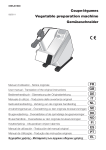
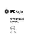
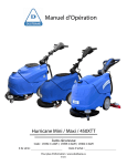
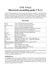
Operations Manual Code: 19674-C-AGM Code: 19675-C-AGM Gladiator 512 and 512 Ride-On Gladiator Series Serial #:_________________________ Date of Purchase:_________________________ More info : www.dustbane.ca 08-2011 1. Index 1. Index 2. General Information 1 2 3. Technical Information 2 4. Safety Information 4 5. Handling And Installation 5 6. Practical Guide For The Operator 6 2.1. Scope of the manual 2.2. Documentation provided with the machine 3.1. General description 3.2. Legend 3.3. Danger zones 4.1. Safety regulations 5.1. Lifting and transporting the packaged machine 5.2. Checks on delivery 5.3. Unpacking 5.4. Lifting and transporting the machine 6.1. Controls – Description 512 Rider 6.2. Controls – Description 512 6.3. Fitting the side brush 6.4. Preparing the machine for work 6.5. Working 2 2 2 3 4 4 5 5 5 6 6 7 8 9 9 7. Periods Of Inactivity 8. Maintenance Instructions 10 10 9. Troubleshooting 15 10. Setting The Control Panel Board 512 Rider 17 8.1. Maintenance - General rules 8.2. Routine maintenance 8.2.1. External side brushes: replacing 8.2.2. Rear bin: replacing 8.2.3. Center brush: replacing 8.2.4. Side brush: replacing 8.2.5. Fuses: replacing 8.2.6. Side brush belt: replacing 8.2.7. Drive belt 512: replacing 8.3. Regular maintenance 8.3.1. Daily operations 8.3.2. Weekly operations 8.3.3. Six monthly operations 9.1. How to resolve possible problems 512 10 11 11 11 12 12 13 13 14 14 14 14 14 16 2. General Information Read this manual carefully before carrying out any work on the machine. 2.1. Scope of the manual This manual has been written by the Manufacturer and is an integral part of the machine. It defines the purpose for which the machine has been designed and constructed and contains all the information required by operators. In addition to this manual containing all user information, other publications are available providing specific information for maintenance personnel. Constant respect for the instructions ensures the safety of the operator and the machine, low running costs and high quality results and extends the working life of the machine. Failure to respect the instructions may lead to damage to the operator, machine, floor and environment. Parts of the text requiring special attention are highlighted in bold and preceded by the symbols illustrated and described here. Indicates the need for attention in order to avoid a series of consequences that could cause death or damage to the health of the operator. Danger Indicates the need for attention in order to avoid a series of consequences that could cause damage to the machine or work environment or financial loss. Important Indicates particularly important instructions. Information In line with the company’s policy of constant product development and updating, the Manufacturer reserves the right to make modifications without warning. 2.2. Documentation provided with the machine • • Operations Manual Parts List 3. Technical Information 3.1. General description This machine is a motorized sweeper designed to sweep floors in civil and industrial premises. The sweeper may be used to clean the residues from industrial processes, dust and dirt in general on all relatively even flat hard surfaces such as concrete, asphalt, porcelain stoneware, ceramic tiles, sheet metal, marble, embossed or smooth rubber or plastic mats indoors or outdoors. 2 3.2. Legend A B The main parts of the machine are as follows (fig. A): • • • • • • • • • front bin (fig. A / B, ref. 2) rear bin (fig. A / B, ref. 1) display (fig. A, ref. 3) center brush (fig. A / B, ref. 4), the principal organ of the machine, transfers the dust and debris to the bin. Available in a range of hardnesses and with different bristles, according to the type of material to be picked up. side brush (fig. A / B, ref. 5), conveys the dust and debris, used exclusively to clean edges, corners and profiles. suction filter (fig. A / B, ref. 6), filters air drawn in by the suction fan. suction fan, enables the machine to sweep without raising dust. filter shaker, used to clean the suction filter. battery charger display (fig. A / B, ref. 7) 3 3.3. Danger zones A. B. C. D. E. Control panel: danger of short circuit. Center brush: danger due to brush rotation. Side brush: danger due to brush rotation. Back/front wheels: danger of crushing between the wheel and chassis. Motor compartment: danger of short circuit between the poles of the battery. 4. Safety Information 4.1. Safety regulations Read the “User manual” carefully before start-up and use, or before performing maintenance or any other work on the machine. Important • • • • • • • • • • • • • • • • • 4 Rigorously respect all instructions in the Manual (in particular those relating to danger and important information) and on the safety plates fitted to the machine. The Manufacturer declines all liability for damage to people or things resulting from failure to observe the instructions. The appliance must be used exclusively by persons trained in its use and/or who have demonstrated their ability and have been expressly instructed to use the appliance. The machine must not be used by minors. The machine must not be used for purposes other than those for which it was expressly designed. Scrupulously respect all safety standards and conditions applicable to the type of building in which the machine is to be operated (eg: pharmaceutical companies, hospitals, chemicals, etc). Do not use the machine in places with inadequate lighting or explosive atmospheres, on public roads, in the presence of dirt hazardous to health (dust, gas, etc) and in unsuitable environments. The machine is designed for use at temperatures of between +4°C and +35°C. When the machine is not being used, the temperature range is +0°C and +50°C. The machine is designed to work in a humidity of between 30% and 95%. Never pick up flammable liquids or explosives (eg. petrol, fuel oil, etc), acids and solvents (eg. paint solvents, acetone etc.). Never pick up flaming or incandescent objects. Never use the machine on slopes or ramps of more than 2%. In the case of slight slopes, do not use the machine transversally, always maneuver with care and do not reverse. When transporting the machine on steeper ramps or slopes, take the utmost care to avoid tipping up and/or uncontrolled acceleration. Never park the machine on a slope. The machine must never be left unattended with the motor on. Before leaving it, turn the motor off, make sure it cannot move accidentally. Always pay attention to other people, children in particular, present in the place where you are working. Never use the machine to transport people or things or to tow anything not permitted by the manufacturer. Do not tow the machine. Never rest objects of any weight on the machine for any reason. Never obstruct ventilation and heat dispersion slits. Never remove, modify or circumvent safety devices. Numerous unpleasant experiences have shown that a wide range of personal objects may cause serious accidents. Before beginning work, remove jewelry, watches, ties, etc. • • • • • • The operator must always use personal protection devices: protective apron or overalls, non-slip waterproof shoes, rubber gloves, protective goggles and ear protectors and mask to protect the respiratory tract. Keep the hands away from moving parts. In the case of malfunction and/or faulty operation, turn the machine off immediately and do not tamper. Contact a service center authorized by the Manufacturer. All maintenance operations must be performed in an adequately lit place. All work on the electrical system and all maintenance and repair operations other than those explicitly described in this manual must be performed by specialized personnel expert in the sector only. Only original accessories and spare parts supplied by the Manufacturer may be used in order to guarantee safe problem-free operation of the machine. Never use parts removed from other machines or from other kits. Special waste. Do not dispose of with ordinary waste. • • If you decide to stop using the machine, you are recommended to remove the batteries and dispose of them at an authorized collection center. You should also make sure that all parts of the appliance which could represent a hazard, particularly to children, are made safe. 5. Handling And Installation 5.1. Lifting and transporting the packaged machine Important During all lifting operations, make sure the packaged machine is firmly anchored to avoid it tipping up or being accidentally dropped. Always load/unload lorries in adequately lit areas. The machine, packaged on a wooden pallet by the Manufacturer, must be loaded using suitable equipment. A fork lift truck must always be used to lift the packaged body of the machine. Handle with care to avoid knocking or overturning the machine. 5.2. Checks on delivery When the carrier delivers the machine, make sure the packaging and machine are both whole and undamaged. If the machine is damaged, make sure the carrier is aware of the damage and before accepting the goods, 5.3. Unpacking Important When unpacking the machine, the operator must be provided with the necessary personal protection devices (gloves, goggles, etc) to limit the risk of accident. 5 Unpack the machine as follows: 1. cut and remove the plastic straps using scissors or nippers; 2. remove the cardboard; 3. depending on the model, remove the metal brackets or cut the plastic straps fixing the machine chassis to the pallet; 4. using a sloping ramp, push the machine backwards off the pallet; 5. move the machine away from the packaging. The packaging may be kept as it can be reused to protect the machine if it is moved to another site or to a repair workshop. Otherwise it must be disposed off in compliance with current legislation. 5.4. Lifting and transporting the machine Important All phases must be performed in an adequately lit room and adopting the safety measures most appropriate to the situation. The operator must always use personal protection devices. To load the machine onto a means of transport, proceed as follows: 1. 2. 3. 4. empty the bin place the machine on the pallet and fix it with plastic straps or metal brackets; lift the pallet (with the machine) using a fork lift truck and load it onto the means of transport; anchor the machine to the means of transport with cables connected to the pallet and machine itself. 6. Practical Guide For The Operator 6.1. Controls – Description 512 Rider The machine has the following controls and indicator lights: • • • • 6 On/OFF switch (ref. 1): turns the machine on and off Emergency button (fig. A, ref. 16): enables/disables all functions of the machine. Suction button (ref. 2): enables/disables the suction function. Brush button (ref. 3): enables/disables brush operation. Filter shaker button (ref. 4): enables the filter shaker. Battery charge LED (ref. 5): 3 LEDs indicating the battery charge: • green light battery fully charged • yellow light battery almost flat, recharge • red light battery flat • Center brush pressure LED (ref. 6): 6 LEDs indicating the pressure of the center brush on the work surface. The pressure exerted by the brush on the floor is calculated by means of the current absorbed by the center brush motor: • green lights, light pressure • yellow light, medium pressure • red light, heavy pressure • If the red light (LED 6) comes on, all LEDs start flashing. Note: Two minutes after the red light comes on, the brush function is shut down automatically. • • A • • • • • • • Center brush pressure regulation handle (fig. A, ref. 8): regulates the pressure of the brush on the floor. Accelerator knob (fig. A, ref. 9): sets the speed of the machine. Front flap raising knob (fig. A, ref. 10): raises the front flap to collect bulky debris. Side brush lifting lever (fig. A, ref. 11): raises and lowers the side brush. Direction selector (ref. 7): sets movement of the machine to forwards or reverse Display (ref. 8): displays alarm codes Brake (fig. A, ref. 12): parking brake (ACTIVATED VIA THE WHITE LEVER) and service brake 6.2. Controls – Description 512 7 The machine has the follow controls and indicator lights: • On/OFF switch (fig. C, ref. 1): turns the machine on and off Suction button (fig. C, ref. 2): enables/disables the suction function. Filter shaker button (fig. C, ref. 4): enables the filter shaker. Battery charge LED (fig. C, ref. 5): 3 LEDs indicating the battery charge: • green light battery fully charged • yellow light battery almost flat, recharge • red light battery flat Suction LED (fig. C, ref. 9): indicates the suction status ON/OFF • • • • • Center brush pressure regulation handle (ref. 8): regulates the pressure of the brush on the floor. Drive knob (ref. 9): enables the drive of the machine. Front flap raising knob (ref. 10): raises the front flap to collect bulky debris. Side brush lifting lever (ref. 11): raises and lowers the side brush. Brake (ref. 12): parking brake • • • • 6.3. Fitting the side brush This operation must be performed with the machine off and key removed Important Proceed as follows: 1. Lift the front of the machine 2. Fit the brush and fix it in place with the washer and screw provided (ref. 1). 3. Unscrew the two screws (ref. 1), adjust the height of the brush and tighten the screws again. 8 6.4. Preparing the machine for work Before starting work, wear overalls, ear protectors, non-slip shoes, mask to protect the respiratory tract, gloves and all other personal protection devices necessitated by the work environment. Check that all switches on the control panel are in the “0” (off) position. Make sure you connect the terminals marked with a “+” to the positive poles of the battery. Do not check the battery charge by sparking. Meticulously follow the instructions given below as short circuiting the batteries could cause them to explode. Important 1. Rotate the top cowling through 90° towards the back of the machine 2. Place the battery/ies into the compartment. 3. Connect the battery/ies. Mount the batteries on the machine using means suitable for their weight. The positive and negative poles have different diameters. Important 6.5. Working Information If you are using the machine for the first time, we recommend trying it on a large obstacle-free surface first to acquire the necessary familiarity. Starting up/use 512 RIDER: Information The seat has a safety sensor which allows the machine to move only when the operator is seated. Prepare the machine as described in the above paragraph. 1. 2. 3. 4. 5. 6. 7. Lift the side brush using the lifting lever. Turn the key switch to the “1” position. Check the LEDs to make sure the battery/ies is sufficiently charged. If not, charge the batteries. Press the brush button when the brushes are active, the LED on the button comes on. Pressing it again stops the brushes, the suction motor comes on automatically. Use the accelerator knob to activate the drive. Adjust pressure of the centre brush on the floor using the knob according to the type of floor and dirt to be picked up. Turn it clockwise to increase pressure and anticlockwise to reduce pressure on the work surface. 8. Lower the side brush using the lever. 9. Start cleaning, maneuvering the handgrip with the hands and acting on the drive control. Starting up/use 512 1. 2. 3. 4. Prepare the machine as described in the above paragraph. Lift the side brush using the lifting lever. Turn the key switch to the “1” position. Check the LEDs to make sure the battery/ies is fully charged. If not, charge the batteries. 9 5. Open the cowling and use the internal combustion engine starting handle. When the engine is cold, you also need to use the choke (INTERNAL COMBUSTION ENGINE with manual pull start). 6. Use the lever to activate the drive. 7. Press the suction button. 8. Adjust pressure of the center brush on the floor using the knob according to the type of floor and dirt to be picked up. Turn it clockwise to increase pressure and anticlockwise to reduce pressure on the work surface. 9. Lower the side brush using the lever. 10. Start cleaning, maneuvering the handgrip with the hands and acting on the drive control. Important To avoid damaging the surface of the floor to be treated, avoid rotating the brushes with the machine stationary. Do not pick up wire, string or plastic straps. Important Important Each 30 minutes of work, activate the filter shaker button (fig. C, ref. 4) for 30 seconds to clean the suction filter. During this operation, the suction fan shuts off automatically. 7. Periods Of Inactivity 1. Disconnect the battery. To optimize the working life of the battery, it should be charged every 30/40 days. 2. Empty the bins. 3. Clean the machine in general. 4. Clean the suction filter. 8. Maintenance Instructions Danger Danger Maintenance on the electrical circuit and all other operations not explicitly described in this manual must be performed by specialized personnel only, in compliance with current safety legislation and as described in the maintenance manual. For all maintenance on the engine, see the instruction book. Never perform any maintenance operations without first disconnecting the batteries from the machine’s electrical circuit. 8.1. Maintenance - General rules Performing regular maintenance according to the Manufacturer’s instructions improves performance and extends the working life of the machine. When cleaning the machine, respect the following: 1. avoid the use of high pressure washers. Water could penetrate the electrical compartment or motors leading to damage or the risk of short circuit; 2. do not use steam to avoid the heat warping plastic parts; 3. do not use hydrocarbons or solvents as they could damage the cowling and rubber parts. 10 8.2. Routine maintenance 8.2.1. External side brushes: replacing 1. 2. 3. 4. Rotate the cowling. Remove the back wheels Unscrew the screws fixing the flap to the chassis (ref. 1). Replace with new flaps. 8.2.2. Rear bin: replacing 11 • • • • • • Remove the back wheels Remove the rear bin Unscrew the two pins fixing the flap (ref. 3). Grip the flap and pull (ref. 4) Replace the flap, insert the two pins in the relative holes Screw up the fixing pins and assemble the machine. 8.2.3. Center brush: replacing 1. 2. 3. 4. Remove the front bin Unscrew the screws fixing the brush to the shaft. Remove the brush Replace the brush making sure the orientation of the bristles is correct. 8.2.4. Side brush: replacing • • • • 12 Lift the front of the machine Unscrew the screw (ref. 1), remove the worn brush Install the new brush and fix it with the screw (ref. 1). Unscrew the two screws (ref. 1), adjust the height of the brush and tighten the screws. Never use a fuse with a higher amperage than specified. Important If a fuse continues to blow, the fault in the wiring, boards (if present) or motors must be Identified and repaired. Have the machine checked by qualified personnel. 8.2.5. Fuses: replacing 1. 2. 3. 4. 5. 6. Turn the key switch to the “0” position. Rotate the cowling to access the machine compartment Remove the fuse holder cover Check the fuses. Replace with a new fuse. Close the cover again Fuse table: For the complete fuse table, see the spare parts catalogue. 8.2.6. Side brush belt: replacing 1. 2. 3. 4. 5. 6. 7. 8. Rotate the top cowling. Remove the pulley (ref. 2) belt (ref. 1) Unscrew the fixing pin (ref. 3) and side arm hooks (ref. 4) from the idle toothed ring. Remove the belt (ref. 1) from the side arm (ref. 4) Replace the belt Attach the side arm (ref. 4) to the idle toothed wheel again. Screw up the pin (ref. 3). Fit the belt (ref. 1) onto the pulley (ref. 2) 13 8.2.7. Drive belt 512: replacing • • • Rotate the cowling. Remove the belt (ref. 1) from the groove of the pulleys. Fit the new belt (ref. 1) onto the pulleys. 8.3. Regular maintenance 8.3.1. Daily operations 1. Empty the bins. 2. Make sure there are no wires or straps rolled around the center brush. 3. Recharge the batteries according to the procedure described. 8.3.2. Weekly operations 1. Check for wear of the FLAPS. If necessary, replace. 2. Check the condition of the suction air filter and make sure it is undamaged. If necessary, replace. 8.3.3. Six monthly operations • Have the electricity circuit checked by qualified personnel. Table of Maintenance • • • • A : On receipt B : Every 10 hours C : Every 50 hours D : Every 100 hours CHECK Center brush: make sure there are no straps or nylon cord wrapped around the brush. If necessary, remove 14 A B C Center brush: check wear of the brush Side brushes: check wear of the brushes Flap / Bin gasket: check wear of the flaps and gaskets D Dust filter: check that the filter is undamaged and clean Tires: check that the tires are in good condition and without cuts at the sides General control: check that nuts and screws are tight 9. Troubleshooting PROBLEM CAUSE SOLUTION The machine does not function. Battery disconnected. Connect the battery to the machine. The battery is flat. Recharge the battery. The key switch is in the 0 position. Turn the key switch to the “1” position. Emergency button pressed . Release the emergency button. Main solenoid switch faulty. Replace solenoid switch. Fuse blown. Replace fuse. No petrol. Fill the machine. Fuse blown. Replace fuse. Fan switch on OFF. Press the fan switch. Suction relay faulty. Replace relay. Motor malfunction. Replace the motor. Fuse blown. Replace fuse. Brush switch not pressed. Press the brush switch. Suction relay faulty. Replace relay. Led 6 (red) on heavy brush pressure. Reduce the pressure of the center brush on the work surface. Motor malfunction. Replace the motor. Suction motor does not function. The center brush does not turn. Filter shaker not working. Fuse blown. Filter shaker relay faulty. Filter shaker switch not pressed. Filter shaker motor faulty. Side brush does not turn. Damaged belt. Replace the belt. The machine raises dust . Side flaps damaged. Replace flaps. Bin full. Empty the bin. Filter incorrectly positioned. Remove the filter and replace correctly. Worn gaskets. Replace gaskets. Fuse blown. Replace fuse. Microswitch under seat not pressed. Sit correctly on the seat. Drive motor overheated. Turn off the machine and wait for a few minutes. Heat sensor damaged. Replace heat sensor. Damaged drive board. Replace drive board. Motor malfunction. Replace the motor. Accelerator, potentiometer, malfunction. Replace potentiometer. Dust comes out of the fan. Drive motor does not work. 15 9.1. How to resolve possible problems 512 PROBLEM CAUSE SOLUTION The machine does not function. Battery disconnected. Connect the battery to the machine. The battery is flat. Recharge the battery. The key switch is in the 0 position. Turn the key switch to the “1” position. No petrol. Fill the machine. Fuse FU4 blown. Replace fuse FU4. Fan switch on OFF . Press the fan switch. Motor malfunction. Replace the motor. Fuse blown. Replace fuse. Motor malfunction. Replace the motor. Filter shaker switch not pressed. Press the filter shaker switch . Filter shaker motor faulty. Replace filter shaker motor. Side brush does not turn. Damaged belt. Replace the belt. The machine raises dust. Side flaps damaged. Replace flaps. Bin full. Empty the bin. Filter incorrectly positioned. Remove the filter and replace correctly. Worn gaskets. Replace gaskets. Fuse blown. Replace fuse. Motor malfunction. Replace the motor. Suction motor does not function. The center brush does not turn. Filter shaker not working. Dust comes out of the fan. Drive motor does not work. 9.3. Alarms displayed 512 RIDER Acc Accelerator Appears if the accelerator knob (fig. A, ref. 9) is activated before the machine is turned on or after the emergency button has been reset. Release the accelerator knob then action again Pot Potentiometer Appears if the speed potentiometer malfunctions or is faulty. The drive has stopped. Release the knob then action again. If the message continues, the potentiometer could be faulty. Lim Limitation Appears when a mosfet internal thermal limitation problem occurs. The drive has stopped. Release the accelerator knob then action again. If the problem continues, wait for a few minutes. Hot Overheating When the motor overheat sensor trips, wait for a few minutes for the motor to cool down. MoS Mosfet Appears when the mosfet is in short circuit. All machine functions are shut down. bLt Drive block Appears when the battery voltage is too low. Recharge the batteries. AcS Brush control fault Appears when there is a fault in the relay controlling the brush. Turn off the brush motor then turn on again. If the message does not disappear, the relay may be disconnected or the control element on the board may be faulty. AcA Suction control fault Appears when there is a fault in the relay controlling the suction. Turn off the suction motor then turn on again. If the message does not disappear, the relay may be disconnected or the control element on the board may be faulty. NoFR 16 General solenoid switch KM1 fault. Appears when the general solenoid switch is faulty. Turn the machine off then on again. If the message does not disappear, the solenoid switch may be faulty disconnected or disconnected, or the control element on the board may be faulty. 10. Setting The Control Panel Board 512 Rider Important If the control board is replaced, make sure the dip switches are set according to the type of machine being used. SW2 ( ON ) = AGM batteries SW3 ( ON ) = “RIDER” version 17