1
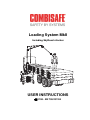
Loading System MkII
Including SkyReach Anchor
USER INSTRUCTIONS
0158 - EN 795:2012-E
CONTENTS
General ............................................................................................................ 3
Quick Guide.................................................................................................. 4
Safety Instructions ........................................................................................... 5
Remember.................................................................................................... 8
Technical Data ................................................................................................. 9
Main Parts .................................................................................................... 9
Loading System MkII Base ......................................................................... 10
SkyReach Anchor....................................................................................... 12
Optional Items ............................................................................................ 17
Assembly ....................................................................................................... 20
Assembling the Loading System MkII ........................................................ 20
Dismantling................................................................................................. 35
Transportation ................................................................................................ 36
Storage .......................................................................................................... 38
Loading System MkII Base ......................................................................... 38
SkyReach Anchor....................................................................................... 39
Recommended operating method .................................................................. 40
Single Unit usage ....................................................................................... 40
Double Unit usage ...................................................................................... 41
Maintenance .................................................................................................. 43
Check list prior to usage ............................................................................. 43
Cleaning ..................................................................................................... 44
Recycling .................................................................................................... 45
© Combisafe International AB
UI Loading System MkII-EN-1527
Subject to changes.
Loading System MkII
General
General
The Loading System MkII has been designed to ease the loading and
unloading of equipment from the top of a flatbed delivery lorry/trailer in a safe
manner.
The Loading System MkII incorporates a SkyReach Anchor unit which itself
shall be attached by a Retractable Fall Arrest Block to connect to the full body
safety harness worn by the operative.
The SkyReach Anchor is designed to deform, absorb the energy and reduce
the arising forces, when a fall occurs.
When working at lower heights, the standard Loading System MkII can be
used. This configuration gives a total height of 4,7 metres and allows the
operative to work up to 4,3 metres in height from ground level. When working
at higher positions the system can be equipped with the SkyReach Adaptor
5.9 which gives 5,9 metres in height from the ground to the anchor point
position. This allows the operative to work up to 5,5 metres in height from
ground level.
The combination Loading System MkII and SkyReach, is tested to prove
compliance with EN 795:2012 Type E standard, and is CE-certified by
DEKRA EXAM GmbH, Dinnendahlstraße 9, 44809 Bochum, Germany, with
identification no 0158.
The Loading System MkII can be used on a construction site or in a loading
yard and it can be moved to alternative locations as needs arise. To ease
transportation and storage, the Loading System MkII is designed to be flat
packed and stackable. When flat packed the total height of the base is 0,6 m.
The SkyReach Anchor itself can be separated and folded for ease of transport
between locations.
When used for unloading a trailer up to 8 m in length, the Loading System
MkII Single Unit can be used. If unloading a trailer between 8 and 14 m in
length, the Loading System MkII Double Unit can be used.
Read carefully through this user instruction before any use of the product. In
case of questions and uncertainties, please contact Combisafe for support.
3
General
Loading System MkII
Quick Guide
4
Loading System MkII
Safety Instructions
Safety Instructions
The Loading System MkII is only intended for the purpose stated in this user
instruction, any other usage is not recommended. The product is used to
protect workers operating at height and if used incorrectly, there is a potential
risk of accidents to both the user and other people in the vicinity. Please read
this manual carefully before any usage.
•
Under no circumstances shall the product be used as a makeshift crane or
lifting/lowering device.
•
Under no circumstances shall any items, other than those provided with
the system be used either in replacement or through preference as this
may affect the performance of the product.
•
Care should be taken in the transportation of the product between uses
and locations. If any damage occurs or is detected in any part, the item
should be withdrawn from use, inspected by a trained person and replaced
if required.
•
Care should be taken in the installation of the product and if any damage
occurs or is detected in any part, the item should be withdrawn from use,
inspected by a trained person and replaced if required.
•
The site location where the Loading System MkII is being used should
have a rescue plan in place, in the event of a fall incident.
•
The device is only intended for use by one person at a time. Under no
circumstances shall multiple persons be attached to the device.
•
Where the base is positioned directly onto the ground, as opposed to hard
standing concrete, sole plates of suitable size and strength should be
placed under the feet of the base to safely transmit and sustain a load of
up to 2,5 N/mm².
•
Do not lift the Loading System MkII unit, including any of its components
with crane, except for the SkyReach Anchor unit itself.
•
When a crane is lifting the SkyReach Anchor unit, be aware of the
movements made by the crane and keep workers at a safe distance.
•
The SkyReach Anchor is intended to be used within a zero factor fall
arrest system. Make sure that the anchorage is always overhead and the
lifeline is taut between the anchorage point and the worker.
•
The maximum vertical deflection of the anchor point that can occur during
service is 0,7 m.
•
In case that this product is re-sold outside the original country of
destination, it is essential that the reseller provides user instructions in the
language of the country in which the system is to be used.
5
Safety Instructions
Loading System MkII
•
When referring to included components not produced by Combisafe,
please refer to the specific user guide/manual for that specific item.
•
PFPE that is used together with the Loading System MkII must be CEcertified and approved in the specific country of usage.
•
It is not recommended to use the products stated in this user instruction
when pregnant, suffering from cardiovascular disease, affected by alcohol
or drugs or other health issues that might affect your mental or physical
capacity.
Always check products and equipment before use
Check all component parts of the Loading Systemm MkII before assembly.
Never use damaged or rusty materials, as this can affect safety. Refer to the
check list in the Maintenance chapter which must be followed prior to use.
Never combine products
It is not recommended to install, combine or interconnect products other than
those supplied by Combisafe. Combisafe product liability is limited to correctly
installed Combisafe products only.
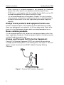
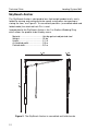
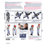
Always use Personal Fall Protective Equipment
Personal Fall Protection Equipment (PFPE) must always be worn during
assembly and dismantling when a risk of falling exists, see Figure 1. This also
applies to work carried out from MEWPs (Mobile Elevating Working
Platforms).
Figure 1. Personal Fall Protection Equipment.
6
Loading System MkII
Safety Instructions
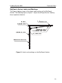
Fall clearance
Note that it is essential that enough free distance is verified to closest
underlying object, please see Figure 2 below.
Figure 2. Explanation of fall clearance.
A:
0,7 [m] Vertical deflection of the SkyReach Anchor Point
B:
X
Braking distance of the PFP-Equipment. Please refer to the
manufacturer´s user manual for specific values.
C:
1 [m]
Safety distance.
Total required fall clearance = A+B+C
7
Safety Instructions
Loading System MkII
Periodic inspection/inspection after a fall
To ensure the function and safety of the system, a safety inspection of the
Loading System Base, the SkyReach Anchor and the PFPE, needs to be
performed by a competent person at least once every 12 months. The
inspections must be documented into a component record.
If an accident has occurred, e.g. a person falling, the items should
immediately be withdrawn from use and inspected by a competent person
according to the manufacturer´s safety check.
Please contact Combisafe for more information regarding inspections and
associated documentation.
NOTE
The SkyReach Anchor is designed to deform when a fall occurs, to
absorb the energy and to reduce the arising forces. When tested,
the maximum vertical deflection of the anchor point is 0,7 m.
Remember
•
Plan fall prevention at an early stage, this will benefit everyone.
•
Use only safety-checked products.
•
Restrict access below and around installation and working area to prevent
injury to others from any fall hazard.
•
Use tools designed for the type of work to be carried out.
•
Keep the installation area in order.
•
A safe workplace is a good workplace.
•
Many fall accidents occur from a low height.
•
Parts might be slippery when wet, be cautious when handling.
8
Loading System MkII
Technical Data
Technical Data
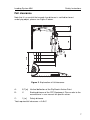
Main Parts
Figure 3. Main parts of the Loading System MkII with the SkyReach Anchor
installed.
Item
Art no.
Designation
Weight
1
8800
Loading System MkII Base
275 kg
2
8100
SkyReach Anchor
25 kg
9
Technical Data
Loading System MkII
Loading System MkII Base
The Loading System MkII Base is a 275 kg steel structure, when loaded with
ballast it is a CE certified attachment to be used as a housing for the
SkyReach Anchor.
Material: .................................... Painted and galvanised/painted steel
Total weight: .............................. 275 kg
Height: ....................................... 2,7 m
Width: ........................................ 1,4 m
Depth:........................................ 1,4 m
#
&
$
'
%
!
"
(
)
Figure 4. Loading System MkII Base.
10
Loading System MkII
Item
Art. no. Designation
Technical Data
Weight
1
11468 Top Column 4.7
27 kg
2
100413 Combistrap, 1 m (2 pcs)
0,2 kg
3
11438 Top Frame
72 kg
4
11431 Corner Post (4 pcs)
5
11432 Bottom Frame
108 kg
6
11518 Foot (4 pcs)
2 kg/pc
10 kg/pc
11
Technical Data
Loading System MkII
SkyReach Anchor
The SkyReach Anchor is designed to be a light weight product and is easily
folded for moving and configured to be space-saving when transporting or
storing the item, see Figure 5. To secure both positions (assembled mode and
folded mode) the attached Lock Pin is used.
Incorporated to the SkyReach Anchor is the 2 m Endless Webbing Sling
which allows the product to be lifted by crane.
Material: .................................... Hot dip galvanised/painted steel
Weight: ...................................... 25 kg
Height: ....................................... 3,1 m
Assembled width: ...................... 2,0 m
Packed width: ............................ 0,2 m
.
/
0
1
0
,
*
/
.
1
-
+
Figure 5. The SkyReach Anchor in assembled and folded mode.
12
Loading System MkII
Technical Data
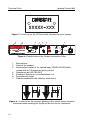
SkyReach Anchor Labels and Markings
The Figure 6 below shows all the labels and markings of the SkyReach
Anchor. The following figures (Figure 7, Figure 8 and Figure 9) are showing
these important elements.
8
2
8
<
5
8
=
7
>
3
4
?
8
5
@
6
7
6
8
9
A
:
<
5
8
=
7
>
?
8
@
6
A
8
;
8
;
B
4
B
C
7
>
D
5
>
A
E
F
>
A
@
6
A
C
G
8
F
7
>
H
C
I
6
F
J
>
C
K
L
6
H
N
O
C
=
7
7
2
>
C
D
<
5
H
>
F
A
E
P
6
F
7
>
>
H
A
@
C
6
L
6
A
M
8
8
5
8
Q
2
F
M
8
H
P
M
>
G
6
<
8
L
6
M
8
5
5
Figure 6. Labels and markings on the SkyReach Anchor.
13
Technical Data
Loading System MkII
Figure 7. A close-up on the ID Plate which includes the serial number.
¡
¢
£
R
R
R
S
T
U
V
W
X
Y
Z
[
\
}
~
z
S
T
U
V
]
^
_
`
a
b
c
d
e
f
g
f
j
d
b
_
d
k
l
m
n
o
o
p
q
r
s
n
t
t
u
v
w
x
y
z
{
|
}
~
|
h
i
h
i
h
Figure 8. Detailed view of the Product Information Label
1.
2.
3.
4.
5.
6.
7.
Manufacturer.
Name of the product.
Identification number of the notified body; DEKRA EXAM GmbH,
responsible for CE production quality control.
Compliance with EN 795:2012.
Pictogram: Read user instruction before use.
Description of usage.
Product combination with different attachments.
¨
§
¨
¨
§
¦
¦
¥
¥
¤
¤
¨
Figure 9. A close-up on the Insertion Marking Label, which shows accepted
tolerances when inserting the SkyReach Anchor into its attachment.
14
Loading System MkII
Technical Data
Personal Fall Protection Equipment
To create a complete system to protect the operative when working at height,
the Loading System MkII needs to be equipped with Personal Fall Protection
Equipment (PFPE). Figure 10 shows an example on how to equip the
SkyReach Anchor with recommended PFPE. All PFPE that is used must be
certified according to valid standards and approved in the specific country of
use.
The following PFPE is approved to be used together with the SkyReach
Anchor and the Loading System MkII:
RTFA ................. Fall arrest blocks certified to EN 360.
Only the Miller Falcon 6,2 m, or the Miller Falcon 10 m
when a Double Unit is used, has been tested and approved
in combination with the Loading System MkII and SkyReach
Anchor, and thus the only RTFA that will remain the system
as CE certified.
Harness .............. Full body harnesses certified to EN 361.
Lanyard .............. Non shock absorbing lanyards certified to EN 354,
to be used separately or in combination with EN 355
certified lanyard, or with a max length of 0,6 m in
combination with the Falcon Fall Arrest Block.
Lanyard .............. Shock absorbing lanyards certified to EN 355.
To be used in separate or in combination with an EN 354
certified lanyard. Must NOT be combined with the Falcon
Fall Arrest Block.
15
Technical Data
Loading System MkII
¬
«
ª
©
Figure 10. The figure shows the SkyReach Anchor equipped with
recommended PFPE.
Item
Part no.
1
8100
2
100605
16
Designation
Weight
SkyReach Anchor (includes item 2)
25 kg
Endless Webbing Sling, 2 m
0,2 kg
3
CM1014237 Miller Revolution 2, Full Body Harness
1,5 kg
4
CM1002889 Miller Extra Webbing, 0.3 m
0,2 kg
5
CM1011729 Miller Falcon Fall Arrest Block, 6.2 m
4 kg
Loading System MkII
Technical Data
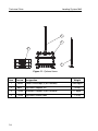
Optional Items
The following items are not delivered as standard together with the Loading
System MkII but can be ordered separately if required, please see Figure 11
for visual clarification of the items
Precast Kentledge (Art. 10663)
This precast concrete block is one out of three possible ballast options, and
can be ordered from Combisafe. Please see the following chapter Ballast for
more information.
Material: ..................................... Concrete
Weight:....................................... 1000 kg
Height: ....................................... 0,25 m
Width:......................................... 1,4 m
Depth: ........................................ 1,4 m
Formwork Support (Art. 11446)
To use any of the other two ballast options, the Loading System MkII Base
needs to be equipped with 8 pcs of the Formwork Support. These channel
steel bars with a wooden inlay will give the support needed as the base is
filled with gravel or concrete.
Material: ..................................... Painted steel/wood
Weight:....................................... 11 kg
Length: ....................................... 1,4 m
SkyReach Adaptor 5.9 (Art. 8801)
When a greater working height is required then the standard Top Column 4.7
contributes, the SkyReach Adaptor 5.9 will give a total height of 5,9 m from
the ground to the anchor point.
Material: ..................................... Hot dip galvanised/painted steel
Weight:....................................... 25 kg
Height: ....................................... 2,4 m
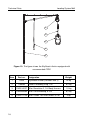
SkyReach Reach Hook (Art. 11530)
The Reach Hook is useful to guide the SkyReach Anchor into the Top Column
4.7/SkyReach Adaptor 5.9 when the anchor is lifted and lowered by crane. It
has got a shaft which is extendable and the length can vary from 1,2 to 2,7 m.
Material: ..................................... Aluminum/Hot dip galvanised steel
Weight:....................................... 1,0 kg
Length: ....................................... 1,2 – 2,7 m
17
Technical Data
Loading System MkII
®
±
°
¯
Figure 11. Optional items.
Item
Part no. Designation
1
10663
Precast Kentledge (3 pcs needed)
2
8801
SkyReach Adaptor 5.9
3
11446
Formwork Support (8 pcs needed)
4
11530
SkyReach Reach Hook
18
Weight
1000 kg/pc
25 kg
11 kg/pc
1,5 kg
Loading System MkII
Technical Data
Ballast
The Loading System MkII Base needs to be loaded with minimum 2800 kg of
ballast to keep stable and meet the requirements in the standard. The ballast
can be applied in three different ways, which are presented below. Further
details on how to perform the ballast loading procedure are described in the
Assembly chapter.
•
Precast Kentledge
The Precast Kentledge is a 1000 kg concrete block designed to fit
into the Loading System MkII Base. Using three units of the Precast
Kentledge is enough to achieve the weight requirement. These
should to be ordered as an option as they are not included as a
standard.
•
Concrete box cast on site
For this option, a package of Formwork Supports should be ordered,
as they are not included in Loading System MkII as a standard. With
the Formwork Supports mounted, a plywood box inside the Loading
System MkII Base will make it possible to cast concrete in the box
directly on site.
•
Gravel box
For this option, a package of Formwork Supports should be ordered,
as they are not included in Loading System MkII as a standard. With
the Formwork Supports mounted, a plywood box inside the Loading
System MkII Base will make it possible to fill up with gravel directly
on site.
19
Assembly
SkyReach Anchor
Assembly
Assembling the Loading System MkII
The following information and illustrations are a step by step guide on how to
rig a Loading System MkII together with a SkyReach Anchor unit successfully.
The Loading System MkII can be used with any of the three ballast options
described. Please refer to the appropriate instruction pertaining to the actual
case.
Before attempting to rig a Loading System MkII unit, please make sure you
have the following tools:
•
Hammer or a 22 mm spanner or an adjustable spanner.
•
Spirit level.
•
Crane for installation of the SkyReach unit.
•
Fork lift truck, or equivalent vehicle, for lifting the device.
NOTE
Except for lifting the SkyReach Anchor unit alone, lifting the
Loading System MkII, or its parts with a crane is not permitted. Use
a fork lift truck and refer to the guides in this document.
Installation instructions for Loading System MkII
1.
20
Make sure that the ground, where the Loading System MkII is placed, is
relatively flat. The Loading System MkII Base has got adjustable feet
which are designed to adjust within a 5 degree inclination. Use a fork lift
truck to handle the Bottom Frame, place the forks underneath the
horizontal tubes and spread the forks apart prior to lifting, see Figure 12.
Place the Bottom Frame on the ground. Use a spirit level to make sure
that the Bottom Frame is level. If not, simply rotate the feet by hand or
use a 22 mm spanner to wrench, or a hammer to strike on the Adjusting
Bar to adjust the feet until the Bottom Frame is level, see Figure 13.
SkyReach Anchor
Assembly
Figure 12. Lifting the Bottom Frame with truck.
Figure 13. Adjustment of the Foot height with a 22 mm spanner.
2.
Place the four Corner Posts into the Bottom Frame, with the welding nuts
facing outwards. (When using the Precast Kentledge as ballast, it is
recommended to only insert the two rear Corner Posts before loading the
ballast.)
Make sure that the Corner Posts are inserted the correct length into the
sleeves, observe the Insertion Marking Label position, see Figure 14.
21
Assembly
SkyReach Anchor
Figure 14. Insertion of the Corner Posts.
NOTE
The lower edge of the Insertion Marking Label on the Corner Posts
must be aligned with the upper edge of the Bottom Frame Posts for
a safe and proper installation. See Figure 15 below for a closer
illustration of the label.
¶
µ
¶
¶
µ
´
´
³
³
²
²
¶
Figure 15. Close-Up of Insertion Marking Label.
22
SkyReach Anchor
Assembly
If using Precast Kentledges as ballast option, please proceed to step 3. If
using cast concrete as ballast option, please proceed to step 4 and if using
gravel as ballast option, please proceed to step 5.
3.
Precast Kentledge ballast option
Check that the two rear Corner Posts are inserted correctly, and the two
front Corner Posts are left beside. Use a forklift truck to place the three
1000 kg COMBISAFE Precast Kentledges onto the Bottom Frame one
after another, see Figure 16. When the concrete blocks are in place,
place the two remaining Corner Posts into the Bottom Frame. Next step
is to mount the top unit, please proceed to step 6.
Figure 16. Placement of last ballast.
4.
Cast-In-Concrete ballast option
4.1 Check that all four Corner Posts are inserted correctly into the Bottom
Frame. Cut a piece of 18 mm Formwork Plywood, complying with EN
636-3, in the format as shown in Figure 17 and place in the centre of the
Bottom Frame. Bolt the eight Formwork Supports to the welding nuts
located on the Corner Posts. Use the bolts attached to the Formwork
Supports, see Figure 18. At this step it is not necessary to tighten the
bolts.
23
Assembly
SkyReach Anchor
·
·
¾
½
¸
·
¹
º
Â
Ã
Å
Ä
¼
»
»
»
¿
Figure 17. Dimensions for the bottom board.
Æ
Ç
È
È
Ç
É
Æ
Ç
Ê
Ë
Figure 18. Example of placement of Formwork Support.
24
Ì
À
À
Á
SkyReach Anchor
Assembly
4.2 Cut twelve 70x45 wooden ribs to 920 mm in length and four pieces of 18
mm Formwork Plywood, complying with EN 636-3, to the format
1285x920 mm and cut out a notch in one corner as shown in Figure 19.
Make four similar side board units according to these instructions, and
then fix the ribs to the boards with wooden screws as in Figure 19.
Í
Î
Ï
á
Ð
Ô
ç
á
Ô
ç
Î
Ð
Ó
Ò
Ñ
Ó
Õ
Ô
Ð
á
â
×
ã
×
Þ
Ú
Ø
Ù
Ý
ß
ä
å
Ð
â
æ
ç
â
Ô
Î
ç
è
é
Ö
×
Ø
Ö
Ù
Ú
Û
Ú
Ü
Ý
Þ
Ú
ß
×
à
Ù
ê
ê
ë
Þ
Figure 19. Dimensions for the concrete side board.
4.3 Place the four Concrete Side Board assembly units equally one after
another onto the Bottom Board located in the Base, with the notch facing
down and the Wooden Ribs leaning towards the Formwork Supports, see
Figure 20. Make sure to place all the units overlapping so that all the
sideboard units get the same support when leaning against the Formwork
Supports.
25
Assembly
SkyReach Anchor
Figure 20. Placement of the side board units.
4.4 When all the sides are in place and the plywood boards create a tight
box, fix the boards with wooden screws if needed. Next step is to mount
the top unit, please proceed to step 6.
5.
Gravel filled ballast option
5.1 Check that that all four Corner Posts are inserted correctly into the
Bottom Frame. Cut a piece of 18 mm Formwork Plywood, complying with
EN 636-3, to the format as shown in Figure 21 and place in the centre of
the Bottom Frame. Bolt the eight Formwork Supports to the welding nuts.
Use the bolts attached to the Formwork Support, see Figure 22. At this
step it is not necessary to tighten the bolts.
26
SkyReach Anchor
Assembly
ì
ì
ó
ò
í
ì
î
ï
÷
ø
ú
ù
ñ
ð
ð
ð
ô
õ
õ
ö
Figure 21. Dimension of the Bottom Plywood Board.(Art. 11540)
û
ü
ý
ý
ü
þ
û
ü
ÿ
Figure 22. Example of placement of Formwork Support.
27
Assembly
SkyReach Anchor
5.2 Cut four pieces of 18 mm formwork plywood, complying with EN 636-3, to
the format as shown in Figure 23. Place the boards one after another in
the Base, with the notches facing down, leaning against the Formwork
Supports, see Figure 24. The boards shall be placed onto the Bottom
Frame itself and not onto the Bottom Board. Fix the boards to the
Formwork Supports with wooden screws. When all the boards are in
place and they create a box, go to step 6 for mounting of the Top Frame.
Figure 23. Dimension of the gravel side board. Note that the board has got
notches in both bottom corners.
Figure 24. Placement of the side board units.
28
SkyReach Anchor
6.
Assembly
When using the SkyReach in the Loading System MkII unit, the Top
Column 4.7 can be used to reach a working height up to 4,3 m. If greater
working height is preferred, then chose the SkyReach Adaptor 5.9
instead. With this solution you will reach a working height up to 5,5 m.
The following instructions can be applied to both of the solutions but the
illustrations are showing the Top Column 4.7 only.
With the Top Frame still standing on the ground, insert the Top Column
4.7/SkyReach Adaptor 5.9 unit into the Top Frame, observing that the
Insertion Marking Label is in position, see Figure 25.
Figure 25. Insertion Marking Label on Top Column 4.7.
NOTE
Make sure that the Top Column 4.7/SkyReach Adaptor 5.9 is
inserted the correct length into the Sleeve. Insertion Marking Label
on Top Column 4.7/SkyReach Adaptor 5.9 must be aligned with
upper edge of Top Frame Sleeve for a safe and proper installation.
29
Assembly
7.
SkyReach Anchor
Using a forklift truck, place the forks underneath the horizontal tubes of
the Top Frame, spread the forks as wide as possible and then, if needed,
secure the Top Frame assembly with the two supplied Combistraps
before lifting. Straps shall be attached diagonally to each fork to ensure a
safe lift, see Figure 26 below. Remember that the straps should be
tightened firmly.
Figure 26. Use the included Combistraps to secure the Top Frame to the
forks prior to lifting.
8.
Lift the assembled top unit high enough above the Corner Posts, and
slowly lower the assembly when the four Top Frame Legs can be slotted
into the Corner Posts. If Formwork Supports are bolted to the Corner
Posts, make sure they are not tightened, thus it can prevent the Top
Frame from being inserted in an easy way. Lower the assembly slowly
and make sure it runs smoothly down into the Corner Posts.
Make sure the assembly is inserted the correct length by checking that
the lower edge of Insertion Marking Labels are aligned with upper edge of
Corner Posts, see Figure 27.
With the Top Frame in place, the Formwork Supports can be tightened
firmly, if they are being used.
30
SkyReach Anchor
Assembly
Figure 27. Insertion of Top Frame to Corner Posts. Note the position of
Insertion Marking Label when Top Frame is slotted into the Corner Posts in
the illustration to the left.
9.
Now the Loading System MkII Base is completed as an assembled unit
and next step is to fill the Base with chosen ballast, if concrete or gravel
is preferred as ballast option.
If concrete is the chosen ballast option, fill the box in the base with 2400
3
kg/m concrete. Fill all the way to the top edge of the side boards.
NOTE
The density of the concrete mix shall under no circumstances be
3
less than 2400 kg/m , otherwise the ballast will not meet the
minimum weight requirements according to the standard.
If gravel is the preferred ballast option, fill the box up with gravel, compact
well and make sure that the gravel reaches the top edge of the side
boards.
NOTE
The density of the gravel shall under no circumstances be less than
3
1780 kg/m , otherwise the ballast will not meet the minimum weight
requirements according to the standard.
31
Assembly
SkyReach Anchor
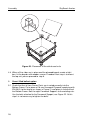
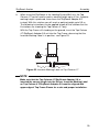
10. Installation instructions for the SkyReach Anchor
10.1 Mount the SkyReach Anchor from the folded position in four easy steps,
please see Figure 28:
1.
Remove the Lock Pin and release the SkyReach Anchor Brace
and Boom.
2.
Arrange the position of the Boom.
3.
Move the SkyReach Anchor Brace and make sure that the brace
hook bracket (detail A) fits into the lower lugs (detail B).
4.
Secure the position from step 3 with the attached Lock Pin as
shown in view C.
Figure 28. Assembly process of the SkyReach Anchor
32
SkyReach Anchor
Assembly
NOTE
Make sure that the Lock Pin is properly installed, latch is dropped
and that it is secured with the wire. Under no circumstances shall a
substitute Lock Pin other than ones provided by Combisafe be
used.
10.2 Connect the Fall Arrest Block. Make sure that the component is correctly
attached and secured to the SkyReach Anchor point. Figure 29 is
showing how the 6,2 m Falcon Fall Arrest Block is attached to the anchor
point.
Figure 29. Attaching the 6,2m Fall Arrest Block.
NOTE
It is strongly recommended that a rope is tied to the Fall Arrest
Block karabiner to enable the operative to retrieve the reel and allow
simple connection to the operatives 0.3 m extra webbing. It is not
recommended to leave only the lifeline of the block pulled out in this
matter, due to possible damage to the reel.
33
Assembly
SkyReach Anchor
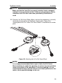
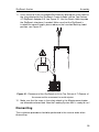
10.3 Make sure that the incorporated Endless Webbing Sling is attached
correctly, see Figure 30. The Sling is used for positioning and repositioning of the SkyReach Anchor to the required location in the Top Column
4.7/SkyReach Adaptor 5.9.
Figure 30. Detail of sling installation.
NOTE
Use only the sling supplied by Combisafe. Use the sling only for the
purposes described in this user instruction. Please read the
provided user manual for the Endless Webbing Sling.
34
SkyReach Anchor
Assembly
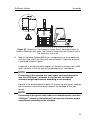
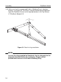
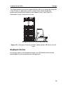
11. Use a crane to lift the assembled SkyReach by placing the crane hook to
the sling attached to the SkyReach. Lower it down into the Top Column
4.7/SkyReach Adaptor 5.9, see Figure 31. Use the Reach Hook to guide
the SkyReach into place if needed. Make sure that the SkyReach is
inserted the correct length, please observe the Insertion Marking Label
position, see Figure 31.
Figure 31. Placement of the SkyReach unit into Top Column 4.7. Beware of
the crane and its movement to avoid injuries.
12. Make sure that the steps in the safety check in the Maintenance chapter
are followed and executed. Now the Loading System MkII is ready to use!
Dismantling
The installation procedure should be performed in the reverse order when
dismantling.
35
Transportation
Loading System MkII
Transportation
If there is a need for moving the Loading System MkII, once the unit is
assembled and loaded with ballast, it is important that it is handled the correct
way to prevent lifting accidents.
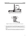
1.
Use a fork lift truck, or equivalent vehicle, place the forks underneath the
Base with the forks as wide as possible, see Figure 32. Lift the unit slowly
and make sure that no part on the Loading System MkII might be stuck,
and thereby preventing it from being lifted smoothly.
NOTE
A fully loaded Loading System MkII weighs approximately 3500 kg, it
is important that a lifting device with a capacity exceeding that value
is used.
2.
Lift the unit and adjust the Feet to their fully inserted position to prevent
damage during movement
3.
Make sure the unit is lifted high enough to pass any obstacle in the
planned way of transportation and move it to the new location. Lower the
unit to the ground and make sure it is level by adjusting the feet into
desired position. When Loading System MkII is level, remove vehicle and
execute the safety check over again.
NOTE
A complete Loading System MkII unit shall not under any
circumstances be lifted with a crane and/or slings!
36
Loading System MkII
Transportation
Figure 32. Lifting the whole unit for transportation.
37
Storage
Loading System MkII
Storage
Always store Combisafe products in a dry and ventilated area protected from
the effects of the weather and from corrosive substances.
Loading System MkII Base
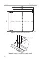
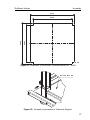
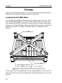
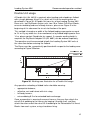
The Loading System MkII is designed to ease storage when not in use. Since
the units can be packed flat, it is easy to store them in a pile. To make sure
the Loading System MkII is packed the correct way after usage, please place
the parts as in Figure 33 below. Make sure that the Feet are fully inserted and
that the Top Frame is resting on the bottom plates in the Bottom Frame
Sleeves.
-
$
.
&
#
!
"
#
$
%
&
'
"
(
)
$
$
!
"
*
+
$
,
!
Figure 33. Loading System MkII Base in packed mode.
A total amount of 6 flat packed units can be stacked together in one stack. On
each Top Frame there are four guide plates located to guide the next unit into
position.
38
Loading System MkII
Storage
The flat packed version of the Loading System MkII must always be lifted with
a fork lift truck, or equivalent vehicle, and the forks always be placed
underneath the horizontal chords of the Bottom Frame, see Figure 34.
Remember to only lift one unit at a time.
Figure 34. Placement of the 6th packed Loading System MkII with a fork lift
truck.
SkyReach Anchor
As already shown in the Assembly chapter, the SkyReach Anchor can be
folded together to ease packing and transportation.
39
Recommended operation method
Loading System MkII
Recommended operating method
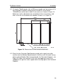
Single Unit usage
For unloading a flatbed with a length of up to 8 m, which will fit into the
loading zone as described in Figure 35, a Single Unit is required (Art. 8806).
The Single Unit consists of one Loading System MkII Base, one SkyReach
Anchor, one 6,2 m Falcon Fall Arrest Block, one extra webbing and one full
body harness, please see Figure 3 in the beginning of this document.
This method is based on a width of the flatbed loading area greater or equal
to 2,4 m. By any width less than mentioned, please contact Combisafe for
support. If a greater working height is required, the SkyReach Adaptor 5.9
(Art. 8801) can be ordered separately.
The Base must be positioned centrally to the zone, as shown below.
=
/
3
>
/
9
7
5
0
?
@
1
A
2
3
/
?
4
5
6
1
1
:
8
B
;
<
<
Figure 35. Working area illustration for a Single Unit usage.
Any operative unloading a flatbed trailer should be wearing:
•
appropriate footwear,
•
reflective vest and helmet with chin strap,
•
full body harness,
•
extra webbing 0.3 m for extended back anchorage.
Once an operative is wearing the correct harness they can then attach the
extra 0.3 m webbing to the harness by looping it through itself, and then
attach the other end of the extra 0.3 m webbing to the Retractable Fall Arrest
Block, using a karabiner fixing.
NOTE
The operative must be connected to the system before accessing
the flatbed.
40
Loading System MkII
Recommended operation method
Double Unit usage
A Double Unit (Art. 8810) is required, when loading and unloading a flatbed
with a length between 8 and 14 m, which will fit into the working zone as
described in Figure 36. A Double Unit consists of two Loading System MkII
Base units, two SkyReach Anchor units, two 10 m Falcon Fall Arrest Blocks,
one extra webbing and one full body harness, please see Figure 3 in the
beginning of this document for visual clarification of the parts.
This method is based on a width of the flatbed loading area greater or equal
to 2,4 m. By any width less than mentioned, or by flatbed length greater than
14 m, please contact Combisafe for support. If a greater working height is
required, the SkyReach Adaptor 5.9 (Art. 8801) can be ordered separately.
The operative must be connected to both the Loading System MkII units at
the same time before entering the flatbed.
The Bases must be symmetrically positioned with respect to the loading zone
according to Figure 36 below.
S
C
G
T
C
O
M
I
D
U
V
E
W
F
G
C
H
U
I
J
P
N
K
Q
L
R
R
L
L
Figure 36. Working area illustration for a Double Unit usage.
Any operative unloading a flatbed trailer should be wearing:
•
appropriate footwear,
•
reflective vest and helmet with chin strap,
•
full body harness,
•
extra webbing 0.3 m for extended back anchorage.
Once an operative is wearing the correct harness they can then attach the
extra 0.3 m webbing to the harness by looping it through itself, and then
attach the other end of the extra 0.3 m webbing to the Retractable Fall Arrest
Blocks from each system, using a karabiner fixing.
41
E
E
Recommended operation method
Loading System MkII
NOTE
The Retractable Fall Arrest Block should be a 10 m Falcon Fall
Arrest Block to allow the operative to move freely to the far extents
of the trailer.
The operative must be connected to both systems before accessing
the flatbed.
Make sure that the lifelines from each retractable block doesn´t
cross, they should at all times run smoothly in their own reel.
42
Loading System MkII
Maintenance
Maintenance
Check list prior to usage
Checking of the system shall be performed before each use, if any of the
listed statements below are not satisfied make sure to correct any issue
before using the product.
Checking includes the following steps:
Loading System MkII Base unit:
•
Ensure that there is no weld damage or deformation to any part of the
system.
•
Ensure that no corrosion that can affect the strength of the system has
occurred.
•
Ensure that the Feet are fully adjustable.
•
Ensure that the Base unit is level.
•
Ensure there are no loose parts e.g. gravel, dirt, concrete etc. in any
sleeves or tubes where another part shall be inserted.
•
Ensure that the threads on the welding nuts on the Corner Posts are free
from dirt or other that can prevent correct fastening of the bolt. If not using
the Formwork Supports, short M12 bolts can be placed in the nuts to
protect the threads.
•
Ensure that there is no damage to the Precast Kentledge concrete blocks,
if such are used.
•
Ensure that all items with the insertion marking label on, are readable and
are inserted the correct length.
•
Ensure the legibility of the product marking.
43
Maintenance
Loading System MkII
SkyReach Anchor:
•
Ensure that no drill holes have been made.
•
Ensure that no corrosion that can affect the strength of the product has
occurred.
•
Ensure there are no weld damages or deformation to any part of the
product.
•
Ensure that there are no damages to the Lifting Eye neither to the welds
attached to the Eye.
•
Ensure that all bolts are tightened securely.
•
Ensure that the Lock Pin is connected to the wire attached to the lower lug
on the mast, it is fitted correctly in place, and that it is not damaged or
deformed.
•
Ensure the legibility of the product marking.
•
Ensure that the Hook at the end of the brace is not damaged, and that it
can be smoothly placed into the lower lugs on the mast when performing
the mounting.
•
Ensure that the Fall Arrest Block or lanyard is completely secured to the
Anchor Point.
•
Ensure that SkyReach Anchor is fully engaged into the Loading System
MkII unit and is free to rotate.
•
Ensure there are no damages to the Endless Webbing Sling.
PFP-Equipment:
•
Please follow the manufacturer´s recommendations for safety and
checking.
If any of the listed statements above are not satisfied, correct any issue before
usage of product.
Cleaning
Periodically clean the exterior of the parts. Wipe all parts to remove grease or
dirt using a damp cloth and if needed use mild detergent, towel dry.
Do not use any detergent that could affect the strength of the parts.
44
Loading System MkII
Maintenance
Recycling
When the Loading System MkII has been taken out of service it can be
recycled as steel.
Plastic plugs can be recycled according to material specification on the items.
45
COMBISAFE International AB
Storsjöstråket 15, SE-831 34 Östersund
Tel.: +46 (0)63 150 260, Fax: +46 (0)63 129 330
[email protected], www.combisafe.com