1
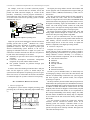
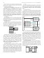
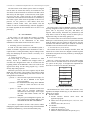
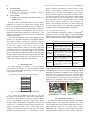
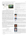
S.-P. Moon et al.: Embedded Linux Implementation on a Commercial Digital TV System The data written in the address spaces which are mapped into the MCU as external bus memory are transferred to the write buffer of the PCF8584 device and sent to the SDL (serial data line) by the shift register. At the same time, clock signals are sent to the SCL (serial clock line) by the parallel bus control block. These data and clock transfers are controlled by the control register within the PCF algorithm for the I2C bus protocol- I2C bus protocol is what defines fixed slave addresses, transfer modes, ACK, start transfer, and end transfer for inter IC communication[6], and PCF algorithm is the control algorithm for the PCF8584 device for the I2C bus protocol[7]. IV. LINUX PORTING In this section, we will explain the sequence of porting Linux with respect to the analysis of the component. The sequence consists of the modification of the kernel initialization codes and the creation of the device driver. As a result, it is possible to execute a code (head.o) without changing the program counter when the image in the flash ROM is loaded into SDRAM. Fig. 7 shows the final memory map. 0x03ffffff 0x03ffffff Special Register Bank Special Register Bank 0x03ff0000 0x03ff0000 External I/O device External I/O device 0x02000000 0x02000000 Not Used Not Used 0x01800000 0x01800000 SDRAM 0x00800000 d c b d Download Image Host PC FLASH ROM 0x01000000 a Linux Image Linux Image FLASH ROM SDRAM Boot Loader Boot Loader 0x00000000 0x00000000 Fig. 6 Kernel image loading sequence Fig. 7 Final memory map The Linux image copied to SDRAM would be executable by being unzipped. In order to perform extractaction, memory spaces such as bss_section, user_stack, and malloc are required. Those memory allocations are performed by link script which is used for an image creation. In these spaces, a zipped Linux image is extracted by gunzip tool. The extracted codes are located in the next address from the malloc space. And relocation process is required since the data under the malloc space isn’t needed. In this process, since the relocation code under the malloc space would be overwritten, it should be moved to the end of the extracted codes. 2) Essential devices for the kernel The essential devices are the interrupt controller, timer, and console device. These devices are mapped to internal registers of the MCU and provide necessary function, by modifying the internal registers. B. Device driver design There are a video processing device and an analog output device as well as essential devices for the kernel in a digital TV system. In this paper, we designed and implemented a device driver for the I2C bus interface (PCF8584). Interface module (i2c-dev.o) Core module (i2c-core.o) Algorithm module (i2c-pcf.o) Adapter module (i2c-adaptor.o) /8 A. Rebuilding of kernel initialization code In order to load Linux kernel to an embedded system, a rebuild of hardware dependent kernel initialization codes is required. This is a setting the memory map for loading a Linux image and modifying the devices which is necessary for a kernel operation. 1) Setting the memory map The Linux image to be zipped is contained in a flash memory, moved to a SDRAM and unzipped while in execution. The unzipped kernel codes are relocated into the beginning address of the SDRAM to remove the codes for the zipped Linux image and the unzip program. Fig. 6 shows memory map setting sequence. When the system resets, the CPU recognizes only the flash ROM area and executes a boot loader at the bottom of flash rom. It plays a role of downloading codes from a host PC and storing them into a flash rom. < process a > the boot loader copies the Linux image of a host PC into a SDRAM in the digital processing module. < process b > the downloaded Linux image in the SDRAM is stored in a flash rom above the boot loader. < process c > then, the system is initialized and the boot loader calls an execution code(head.o) included in the Linux image. And it copies the entire flash ROM contents into the SDRAM. < process d > using the system management registers, the CPU exchanges the beginning address of the flash ROM and with that of the SDRAM. 1405 I2C Bus Master device (PCF8584) SCL SDL I2C Bus Slave device (MSP3440) Fig. 8 Structure of device driver The PCF8584 device driver consists of the interface, core, algorithm, and adaptor modules (Fig. 8). The functions of each module are as follows: Interface module A. Provide interface between device driver and application program. B. Define device file operations (open, read, write, ioctl, release). C. Initialize device file (/dev/i2c0). Core module A. Add/remove an adaptor. B. Define the function of I2C bus. C. Initialize a status information file system (/proc).