1
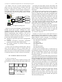
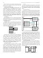
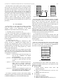
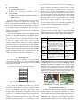
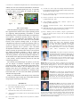
IEEE Transactions on Consumer Electronics, Vol. 49, No. 4, NOVEMBER 2003 1402 Embedded Linux Implementation on a Commercial Digital TV System Sang-Pil Moon, Joo-Won Kim, Kuk-Ho Bae, Jae-Cheon Lee and Dae-Wha Seo, Member, IEEE Abstract — A Digital TV system is necessary for not only video and audio, but also data processing. Especially in the case of bidirectional broadcasting, it should manage the return channel created by the Internet, PSTN, and so on. Because of many functionalities and multitasking jobs, it needs an Operating System. Embedded Linux, as open source program can increase cost effectiveness in the market and has many advantages-reusable device drivers and application programs, more convenient development environment using shell and file system, and easy resolution of problem within the Open Source Community. In this paper, we modified the embedded Linux kernel and the cross development environment for a big-endian system, redesigned device drivers for kernel execution, and configured system memory map in order to load the Linux kernel. Also we developed a device driver for the entire system control.1 Index Terms — Embedded Linux, Digital TV I. INTRODUCTION According to the trend of multimedia in TV system, in order to increase the competitiveness of ground broad- casting services, digital broadcasting services are applied widely. Consequently, the demand for digital TV system is increased. While designing digital TV systems, the hardware applied to existing analog TV systems is not able to support various receiving functions in digital TV systems because it need to perform data processing as well as video and audio. Therefore, a digital TV system needs a high-performance processor and a large amount of memory. Because of this reason, an embedded operating system that can efficiently manage hardware resources is required. There are commercial embedded operating systems such as pSOSTM in digital TV systems. However, the cost of production is high due to expensive royalties when those are used. But if an embedded Linux operating system with open source is used, cost of production can be reduced. In addition, there are other advantages-reduced development time because of open source device drivers and reusable applications, convenient development environment configuration using module function, shell utility and file systems, and easy resolution of a problem from open source communities. In this paper, we will describe an embedded Linux porting in digital LCD projection TV that is able to receive Korean type digital broadcasting program. In order to port it into a digital TV system, we modified the kernel library and the cross development environment into a big endian memory access, redesigned the essential device driver for kernel operations, and configured the system memory map for loading the kernel into main memory. Also, we designed a bus interface device driver to control the entire system. In the remainder of this paper, section 2 discusses the role and necessity of digital TV operating systems. Section3 describes commercial digital TV system structures and its hardware components. Section 4 describes the procedure of Linux porting. Section 5 depicts development environment. Section 6 shows the results of device control and screen output. Finally, concluding is given in section 7. II. DIGITAL TV OPERATING SYSTEM Digital TV provides higher video and audio qualities than analog TV. It has improved scanning line and horizontal resolution for high quality video, and applied AC3 or MPEG2 for high quality audio. However, a more innovative advantage is that it supports data broadcasting services. Data broadcasting services are program dependent, independent services or interactive services using return channel. For these services, a large amount of data needs to be processed. That is, the data to be captured from the digital input stream need to be sorted, stored, and modified for screen output, and on-air TV program would be stored in an embedded hard disk. In addition, if an interactive service should begin, return channels which are created by the Internet and PSTN would be managed and applications such as T-commerce would be performed in digital TV system. Therefore, more data processing would be required [1]. A digital broadcasting signal received by a TV antenna is a stream which includes video, audio, and data. It is demodulated by a RF module, and is extracted MPEG II(video), AC3 or MPEG II(audio), and PAT, CAT, PMT, TSDT(atsc) or NIT, SDT, EIT, TDT(dvb) from a stream[2][3]. 1 S. P. Moon and D. W. Seo are with the school of Electrical engineering and Computer science, Kyungpook National University, Daegu, Korea (email: [email protected], [email protected]). J. W. Kim, K. H. Bae, and J. C. Lee are with the Display Product Research Lab., LG electronics Inc.(e-mail: [email protected], [email protected], [email protected]) This work was supported in part by the LG electronics Inc. Contributed Paper Manuscript received July 29, 2003 0098 3063/00 $10.00 © 2003 IEEE S.-P. Moon et al.: Embedded Linux Implementation on a Commercial Digital TV System For example, in the case of an EPG (electronic program guide) service, the extracted data are modified, stored, and printed onto OSD (On-Screen Display) as a frame. In this procedure, continuously received program information is sorted and stored. At the same time, frames for screen displays are created. These tasks need an operating system to execute simultaneously (Fig. 1). Video, Audio, Data Stream File System Broad casting station Data Sorting Store program or caption data Program Guide (EPG) Real Time weather casting ............. OSD Internet Shopping Mall Internet banking service E-mail service .............. Network System User Input Digital TV Operating System Services Return Channel ex. Internet Contents provider Fig. 1 role of digital TV operating system Digital TV systems on the market have included commercial operating systems such as pSOSTM (Windriver Inc.). These operating systems have advantages of reliability and system optimization. However, there are expensive royalties paid whenever manufacturing system. Whereas, in the case of applying an embedded Linux into a digital TV system, cost effectiveness would be increased since there are no royalties to be paid. Some other advantages are as follows: Reusability of open source device drivers and application programs. Convenient development environment configuration using shell, file system, and the module function. Fast problem resolution for problems through open source community. In order to utilize the advantages mentioned above and port Linux into the digital TV system, we should analyze the system structure and optimize an operating system for its goal. In the next section, we will describe the structure and function of commercial digital TV system as a basis for Linux porting. III. COMMERCIAL DIGITAL TV SYSTEM A. Structure of digital TV The digital TV system consists of digital processing, video processing, RF, LCD driving, and analog output module (Fig. 2.) RF Module LCD Driving Module Analog Output Module DMA Video Processing Module Digital Processing Module Clock Data Digital Module I2C Bus Fig. 2 Digital TV system module structure 1403 The digital processing module controls other modules and execute programs such as EPG(Electronic Program Guide). It consists of MCU, SDRAM, Flash Memory, UART, and I2C bus interface. The video processing module decodes the data captured by the RF module into video, audio, and text information. It consists of a Signal Processor Unit (SPU) and SDRAM which contains data frames being displayed. The RF module receives the digital broadcasting signal, and demodulates it into data stream. The LCD driving module controls the LCD panel which is used to emit light. The analog output module controls video-audio output, deflecting plate, and output signals. The digital processing module controls the RF, LCD, and analog output modules through the I2C(Inter IC)bus. It also controls the video processing module using DMA. When we port an embedded Linux, the most important component is the digital processing module which includes the CPU, Memory, and bus interfaces between the CPU and external output devices. In the next section, we explain the hardware components of the digital processing module. B. Hardware components. In digital TV system, the role of the Linux kernel is to provide effective resource management in order to support a multi-programming environment. For an operating system to manage hardware resources efficiently, it is necessary to analyze the basic hardware components, such as the following: CPU structure and function Endianess Memory map Interrupt controller Timer Serial bus interface External bus interface In order to port an embedded Linux, we should study low level language by taking a closer look at the CPU structure and function. An understanding of instruction sets, system registers and status registers, CPU operation modes, and exception processing are required. The study on memory devices includes memory map and access method. Before the system operates, the embedded Linux kernel is stored in a flash ROM, and is copied to the ram when in operation. In addition to ROM and RAM, the external devices are used frequently. These devices are mapped to a linear memory map and could be accessed in the same manner. So, it is required that we have a deeper understanding of the memory capacity, bus width, and other features. In addition to the memory map, it is important for us to know how the CPU accesses the memory; either big or little enidan. It is also required to analyze the system timer, interrupt controller, and the external bus interface device for an operating system. For example, a scheduler, which is a core function of an operating system, needs a timer that produces periodic interrupts and an interrupt controller that signals the CPU when an interrupt occurs. 1404 IEEE Transactions on Consumer Electronics, Vol. 49, No. 4, NOVEMBER 2003 Finally, an analysis of the system bus connecting the system devices as well as external bus interface between MCU and external devices is required. 1) CPU structure and function The processor core of the digital processing module is the ARM7TDMITM which is a 16/32bit RISC processor. It doesn’t include the MMU(Memory Management Unit). Therefore, while we made application programs, the virtual memory and memory protection didn’t work. Actually, it is possible to directly access memory areas mapped to a device without the OS kernel. The processor core consists of 31 system registers and 6 status registers, has 6 operating modes, and generates 5 exception events-FIQ, IRQ, Abort, Software Interrupt, and Undefined Instruction Trap [4]. 2) Endianess The ARM7TDMI processor core supports both big endian and little endian memory access. But, the MCU(Main Control Unit) which is used in digital TV systems supports only the big endian memory access[5]. 3) Memory map The memory resources of the digital processing module are flash memory which contains the executable programs when the power is off, a SDRAM in which codes are executed, a external I/O area, and MCU’s internal registers. A programmer considers these things as linear address space. 5) Timer The timer of the digital processing module is a 32bit interval mode timer. In order to generate 10msec periodic clock ticks which are the default system time for Linux kernel scheduling, it is configured by setting the counter value and the data register. 6) Serial bus interface A console device is required for messages which are printed during the boot process and is associated with program errors. Because there isn’t any dedicated console devices in a small embedded system, we can check the kernel message using a serial port device such as UART (Universal Asynchronous Receiver Transmitter). The MCU includes 2 identical UART ports and its structure and control block diagram are depicted in Fig. 4. Transmit Buffer Register UTXBUF0-1 (Address : 0x3ffd00c, 0x3ffe00c) TX BaudRate Configuration Value S Y S T E M B U S Transmit Shift Register BaudRate Divisor UBRDIV0-1 (Address : 0x3ffd014, 0x3ffe014) Control Register UCON0-1 (Address : 0x3ffd004, 0x3ffe004) Line Control Register ULCON0-1 (Address : 0x3ffd000, 0x3ffe000) Status Register USTAT0-1 (Address : 0x3ffd008, 0x3ffe008) Buffer Status Line Status 0x03ffffff Special Register Bank 0x03ff0000 0x02000000 External ( 16KB External ( 16KB External ( 16KB External ( 16KB I/O device fixed size) I/O device fixed size) I/O device fixed size) I/O device fixed size) Receive Buffer Register URXBUF0-1 (Address : 0x3ffd010, 0x3ffe010) Not Used SPU RX PCF 8584 Receive Shift Register Not Used Not Used 0x01800000 Fig. 4 UART structure and control block diagram SDRAM 0x00800000 FLASH ROM 0x00000000 Fig. 3 System Memory Map The memory map is configured by the system management registers within the MCU. There are 8M bytes flash ROM, 16M bytes SDRAM, SPU of the video processing module, I2C bus interface device, integrated internal devices, and configuration registers in the system memory map. All of those are divided as banks, and can be configured by special registers (system management registers, external bus control registers, and refresh registers) according to memory type, access clock cycle, capacity and bus width (Fig. 3). 4) Interrupt controller The interrupt controller of the MCU includes 21 interrupt resources (17 from integrated internal devices, 4 from external devices). When the internal or external interrupt signal is transferred, it sends the interrupt request within an interrupt pending register to the CPU[5]. When the CPU receives the interrupt requests, it switches the operating mode to IRQ or FIQ modes according to the interrupt types, branches into a proper service routine for the interrupt with the highest priority among pended requests, and executes that routine. After processing, the CPU switches back to its original mode [4]. The RX/TX buffer and shift registers, which are mapped to the system memory map, provide actual I/O spaces. Line control, UART control, and status registers play a role of checking errors and making decisions for switching between RX/TX modes. In the case of transmission, after the CPU checks the status register to see whether the data in the TX buffer register can be transferred or not, and if the data can be transferred, it would be transferred to a serial line a selected mode and baud-rate of UART control register. 7) External bus interface Since the RF, LCD driving, and analog output modules are controlled through the I2C bus by the MCU, an interface between MCU’s parallel bus and I2C serial bus line are required. In this paper, the PCF8584 (Philips Inc.) has been used. Fig. 5 represents the connection between the MCU and I2C serial bus line. Parallel bus EXT1 0x2004000~0x2008000 8(data) / Write/Read buffer Shift reigsiter SDL SCL A0 (register select) I2C bus ECS1(Chip Select.) CLK(12MHz) Parallel bus control block Control reigister INT(IRQ) MCU Control signals and clock PCF8584 Fig. 5 Connection between MCU and I2C bus S.-P. Moon et al.: Embedded Linux Implementation on a Commercial Digital TV System The data written in the address spaces which are mapped into the MCU as external bus memory are transferred to the write buffer of the PCF8584 device and sent to the SDL (serial data line) by the shift register. At the same time, clock signals are sent to the SCL (serial clock line) by the parallel bus control block. These data and clock transfers are controlled by the control register within the PCF algorithm for the I2C bus protocol- I2C bus protocol is what defines fixed slave addresses, transfer modes, ACK, start transfer, and end transfer for inter IC communication[6], and PCF algorithm is the control algorithm for the PCF8584 device for the I2C bus protocol[7]. IV. LINUX PORTING In this section, we will explain the sequence of porting Linux with respect to the analysis of the component. The sequence consists of the modification of the kernel initialization codes and the creation of the device driver. As a result, it is possible to execute a code (head.o) without changing the program counter when the image in the flash ROM is loaded into SDRAM. Fig. 7 shows the final memory map. 0x03ffffff 0x03ffffff Special Register Bank Special Register Bank 0x03ff0000 0x03ff0000 External I/O device External I/O device 0x02000000 0x02000000 Not Used Not Used 0x01800000 0x01800000 SDRAM 0x00800000 d c b d Download Image Host PC FLASH ROM 0x01000000 a Linux Image Linux Image FLASH ROM SDRAM Boot Loader Boot Loader 0x00000000 0x00000000 Fig. 6 Kernel image loading sequence Fig. 7 Final memory map The Linux image copied to SDRAM would be executable by being unzipped. In order to perform extractaction, memory spaces such as bss_section, user_stack, and malloc are required. Those memory allocations are performed by link script which is used for an image creation. In these spaces, a zipped Linux image is extracted by gunzip tool. The extracted codes are located in the next address from the malloc space. And relocation process is required since the data under the malloc space isn’t needed. In this process, since the relocation code under the malloc space would be overwritten, it should be moved to the end of the extracted codes. 2) Essential devices for the kernel The essential devices are the interrupt controller, timer, and console device. These devices are mapped to internal registers of the MCU and provide necessary function, by modifying the internal registers. B. Device driver design There are a video processing device and an analog output device as well as essential devices for the kernel in a digital TV system. In this paper, we designed and implemented a device driver for the I2C bus interface (PCF8584). Interface module (i2c-dev.o) Core module (i2c-core.o) Algorithm module (i2c-pcf.o) Adapter module (i2c-adaptor.o) /8 A. Rebuilding of kernel initialization code In order to load Linux kernel to an embedded system, a rebuild of hardware dependent kernel initialization codes is required. This is a setting the memory map for loading a Linux image and modifying the devices which is necessary for a kernel operation. 1) Setting the memory map The Linux image to be zipped is contained in a flash memory, moved to a SDRAM and unzipped while in execution. The unzipped kernel codes are relocated into the beginning address of the SDRAM to remove the codes for the zipped Linux image and the unzip program. Fig. 6 shows memory map setting sequence. When the system resets, the CPU recognizes only the flash ROM area and executes a boot loader at the bottom of flash rom. It plays a role of downloading codes from a host PC and storing them into a flash rom. < process a > the boot loader copies the Linux image of a host PC into a SDRAM in the digital processing module. < process b > the downloaded Linux image in the SDRAM is stored in a flash rom above the boot loader. < process c > then, the system is initialized and the boot loader calls an execution code(head.o) included in the Linux image. And it copies the entire flash ROM contents into the SDRAM. < process d > using the system management registers, the CPU exchanges the beginning address of the flash ROM and with that of the SDRAM. 1405 I2C Bus Master device (PCF8584) SCL SDL I2C Bus Slave device (MSP3440) Fig. 8 Structure of device driver The PCF8584 device driver consists of the interface, core, algorithm, and adaptor modules (Fig. 8). The functions of each module are as follows: Interface module A. Provide interface between device driver and application program. B. Define device file operations (open, read, write, ioctl, release). C. Initialize device file (/dev/i2c0). Core module A. Add/remove an adaptor. B. Define the function of I2C bus. C. Initialize a status information file system (/proc). IEEE Transactions on Consumer Electronics, Vol. 49, No. 4, NOVEMBER 2003 1406 Algorithm module A. Initialize PCF8584 device B. Define the function of PCF8584 (i2c_start, i2c_stop(), wait_for_pin()). Adaptor module D. Transfer the data through the memory address to be mapped to MCU. In order to drive the PCF8584 interface device, module initializing are required. In general Linux systems, device drivers are included and initialized at run time. However, in the case of an embedded Linux as a single binary image, these are included statically and initialized at the boot process. Initializing routines within 4 modules are stored in the ‘__init’ symbol of ‘.init’ section and performed by the ‘do_initcalls()’ function while booting. Control data are transferred sequentially beginning from the interface, core, algorithm, and finally to the adaptor modules. The interface module requested by application programs (open, write, read, and ioctl) calls functional interface routines of the core module (master_send(), master_receive(), transfer()) with parameters which are received by application programs. Those of the core module pass the data including slave address, flags and message length to the algorithm module. The algorithm module checks the I2C bus status and the slave address, and sets the control register of the PCF8584. Finally, the adaptor module writes and reads data into the address space which are mapped to the external bus. library is required and likewise in order to make a crosslibrary, a cross-compiler is needed. In order to resolve this problem, first of all, make a cross-compiler using a dummy library (libchack) without the cross-library. And then, create a cross-library using the created cross-compiler. Finally, rebuild the cross-compiler with the cross-library [8].). Fourth, install the tool to make a binary file system image because a ported Linux operates under a ROM file system (read-only) in memory. And install the conversion tool which changes the executable binary format- from a large ELF(Executable and Linkable format) to a small BFLT(Binary Flat format). B. Development environment The development environment consists of SNDS100TM (Samsung) for the test board, JEENITM (Jtag EmbeddedICE Ethernet Interface) for the remote debugger, and the digital TV board(LG Electronics Inc.). Table 1 shows each composition. TABLE 1 DEVELOPMENT ENVIRONMENT Composition Function SNDS100 Test Board Digital TV Board-LG electronics JEENITM Software V. IMPLEMENTATION For Linux porting, we installed a cross development environment on the host PC, set a test environment using the test board which has similar specification, and finally, applied it to the digital TV system. A. Installation of cross development environment Build binutil Kernel Library modify Build gcc(without glibc) Samsung s3c4510B (ARM 7TDMI), 16MByte SDRAM, 1MByte flash ROM, status LED, RJ45 Connector. Samsung s3c4500(ARM 7TDMI), 16MByte SDRAM, 8MByte flash ROM, pcf8584, SPU (LG electronics), 32MByte SDRAM. EPI, Two hardware breakpoints, Ethernet host interface, Internal ARM 710A cached processor. gcc-2.95.3, glibc-2.1.3, binutils2.12, genromfs-0.5.1, elf2flt, gdb5.0, ADS(ARMTM Developer Suite) evaluation ver. 1.1. Network application development board. Digital processing module. Remote debugging environment. Tools for development debugging. cross and The development process was proceeded to make a binary Linux image in the host PC and transfer it to the development board through the serial line. And using JEENI, the remote debugging environment was installed. Also, we made a JTAG (Joint Test Action Group) cable (Fig. 10). The flash ROM boot-block was protected and could not be written on. Thus, we had to detach it from the digital TV board and insert a boot loader into the flash ROM using a ROM programmer, and reattached the flash ROM using IC test socket (Fig. 11). Build glibc Build gcc(with glibc) Install elf2flt, genromfs Fig. 9 Procedure for cross development environment Fig. 9 shows the installation procedure for the cross development environment. First, make binary utilities-linker, assembler, and other object tools (objcopy, objdump)-which is used in all procedures in making a binary Linux image. Second, modify the architecture dependent codes (partial checksum, etc…) in the kernel library because the MCU only support big endian memory access. Third, make crosscompiler and cross-library (Between them, there is a mutual dependent relationship-to make a cross-compiler, a cross- Fig. 10 Development environment Fig. 11 Development board VI. EXPERIMENTAL RESULT As a result, we controlled an audio output IC through the PCF8584. That is, the MSP3440 (Micronas Inc.) which converts digital data to audio output signals. We could hear a beep sound and checks I2C bus signal using a digital oscilloscope. Fig. 12 shows all the data transferred to produce beep sound of some frequency. The first of them is 0x80 (slave S.-P. Moon et al.: Embedded Linux Implementation on a Commercial Digital TV System address), the next is 0x12 0x00 0x14(sub address), and the last is 0x7f (volume) and 0x4e(frequency)[10]. Fig. 13 represents the screen output of the digital TV systems in which the embedded Linux was applied. Fig. 12 Entire data output 1407 [5] s3c4510B user manual ,http://www.samsung.com/Products/Semicond uctor/SystemLSI/Networks/Personal/NTASSP/CommunicationProcessor /S3C4510B/um_s3c4510b_rev1.pdf [6] I2C bus specification, http://www.semiconductors.phiips.com/acroba t/literature/9398 /39340011.pdf. [7] PCF8584 specification, http://www.semiconductors.philips.com/acrob at /datasheets/PCF 8584_ 4.pdf. [8] Craig Hollabaugh, Embedded Linux, Hardware, Software, and Interfacing, Addison Wesley 2002. Fig. 13 Digital TV output [9] VII. CONCLUSIONS With the demand for digital TVs, many commercial models have appeared in the market. These require operating systems for supporting multi-programming environment in which multitasking can be executed. General digital TV systems have used expensive commercial operating systems, which have advantages of code optimization and reliability. But these operating systems increase the overall cost of the products because of the expensive running royalty. If we apply an embedded Linux instead of a commercial operating system, we are able to reduce the cost of the products since Linux is an open-source program, and to provide a more convenient development environment. In this paper, a digital TV system which is currently in the market and is able to receive Korean type digital broadcasting programs is used. It consists of digital processing, RF, video processing, analog output, and LCD driving modules. And the most important component of all the modules is the digital processing module which includes a CPU, memory, and bus interfaces between the CPU and external output devices. The research proceeded through five phases: (i) The first was the analysis of hardware components of the digital processing module. (ii) We modified the Linux kernel codes based on the above analysis. (iii) We designed an I2C bus interface device driver for controlling entire system. (iv)We installed the development environment by modifying target board and tested on a test board with similar specifications with that of the target board. Finally, we confirmed the result through a beep sound from the external audio output control device and captured the data using a digital oscilloscope on the I2C bus. REFERENCES [1] Korea Broadcasting System 2001th annual report-data broadcasting http://tri.kbs.co.kr/pdf/publish/01/6.pdf. [2] Digital Video Broadcasting (DVB): Specification for Service Information (SI) in DVB systems, ETSI EN 300 468 V1.5.1. [3] ATSC Digital Television Standard, Rev.B, ATSC Standard A/53B with Amendment 1. [4] Steve Furber, Stephen B., ARM system-on-chip architecture, AddisonWesley, 2000. Embedded Linux/Microcontroller Project, http://www.uclinux.org /description. [10] “MSP3440G data sheet”, http://www.micronas.com/products/document ation/consumer/msp 34x0g/down loads/msp34x0g_1ds.pdf . [11] John L. Hennessy, David A. Patterson, Computer organization and design: the hardware/software interface, 2nd ed. Morgan Kaufmann Publishers, 1998. [12] Richard Stones, Neil Matthew, Beginning Linux programming, 2nd ed. Wrox press, 1999. Sang-Pil Moon was born in Pusan, Korea, in 1976. He received B.S degree from Kyungpook National University, Daegu, Korea, in 2002. He is currently with the school of Electrical engineering and Computer science, Kyungpook National University, Daegu, Korea. His research interests are in the areas of operating system, wireless communication, and computer architectures. Joo-Won Kim received the B.S. degrees in Electronics from Kyungpook National University, Daegu, Korea, in 1986 the M.S. degrees in Electronics from POSTECH, Pohang, Korea, in 1996. He is a member of the chief research engineer at the LG electronics, Kumi, Korea. His current research interests are in the areas of digital television system and embedded software. Kuk-Ho Bae received the B.S. degree in Electronics from Kyungpook National University, Daegu, Korea, in 1986 the M.S. degree in Electronics from POSTECH, Pohang, Korea, in 1997. He is a member of the chief research engineer at the LG electronics, Kumi, Korea. His current research interests are in the areas of digital television system and software development process. Jae-Cheon Lee received the B.S. and the M.S degrees in Electronics from Kyung-book National University, Daegu, Korea, in 1980 and 1997, respectively. He is a member of the research fellow at the LG electronics, Kumi, Korea. His current research interests are in the areas of digital television system and display pannels Dae-Wha Seo (M’95) received the B.S degree from Kyungpook National University, Daegu, Korea, in 1981 and the M.S and Ph. D. degrees received in Korea Advanced Institute of Science and Technology, Daejun, Korea, in 1983 and 1993, respectively. He was a researcher at the Electronics and Telecommunications Research Institute(ETRI), Daejun, Korea, from 1983 to 1995. He He is currently an associate professor with the school of Electrical engineering and Computer science, Kyungpook National University. His research interests are in the areas of distributed operating systems, parallel & distributed systems and mobile computing.