1
AccuTouch®
Product Manual
Revision F
P/N 821615-000
Elo TouchSystems, Inc.
1-800-ELOTOUCH
www.elotouch.com
Copyright © 1988, 1992, 1994, 1995, 2001 by Elo TouchSystems, Inc.
All rights reserved.
No part of this publication may be reproduced, transmitted, transcribed, stored in a retrieval system,
or translated into any language or computer language, in any form or by any means, including, but not
limited to, electronic, magnetic, optical, chemical, manual, or otherwise without prior written
permission of Elo TouchSystems.
The information in this document is subject to change without notice. Elo TouchSystems makes no
representations or warranties with respect to the contents hereof, and specifically disclaims any
implied warranties of merchantability or fitness for a particular purpose. Elo TouchSystems reserves
the right to revise this publication and to make changes from time to time in the content hereof
without obligation of Elo TouchSystems to notify any person of such revisions or changes.
Trademark Acknowledgements
AccuTouch, IntelliTouch, DuraTouch, and MonitorMouse are registered trademarks, and ELODEV,
TouchUp, TouchBack, SmartSet, and COACH are trademarks of Elo TouchSystems, Inc. All other
trademarks are the property of their respective holders.
iii
iv
LIMITED WARRANTY
CHAPTER0
(a) Elo TouchSystems, Inc., ("Seller") warrants to Buyer that the Products (i)
shall be free of defects in materials and workmanship for five (5) years from the
date of shipment for touchscreen components and controllers (except COACH
chip controller) and two (2) years from the date of shipment for TouchMonitors
(each a "Warranty Period"), (ii) shall conform to Seller's specifications for such
Products throughout the applicable Warranty Period, and (iii) shall be free of
liens and encumbrances when shipped to Buyer. If Seller agrees in writing to
provide and does provide system design, drawings, technical advice, or any
other services to Buyer in connection with Products, then Seller further warrants
to Buyer during the applicable Warranty Period that such services shall be
undertaken in accordance with Seller's reasonable technical judgment based on
Seller's understanding of pertinent technical data as of the date of performance
of such services. Seller's warranties will not apply to any Product with respect to
which there has been (i) improper installation or testing, (ii) failure to provide a
suitable operating environment, (iii) use of the Product for purposes other than
that for which it was designed, (iv) failure to monitor or operate in accordance
with applicable Seller specifications and good industry practice, (v)
unauthorized attachment or removal or alteration of any part, (vi) unusual
mechanical, physical or electrical stress, (vii) modifications or repairs done by
other than Seller, or (viii) any other abuse, misuse, neglect or accident. In no
circumstance shall Seller have any liability or obligation with respect to
expenses, liabilities or losses associated with the installation or removal of any
Product or the installation or removal of any components for inspection, testing
or redesign occasioned by any defect or by repair or replacement of a Product.
(b) Seller makes no warranty regarding the model life of monitors. Seller's
suppliers may at any time and from time to time make changes in the monitors
delivered as Products or components.
(c) Buyer shall notify Seller in writing promptly (and in no case later than thirty
(30) days after discovery) of the failure of any Product to conform to the
warranty set forth above, shall describe in commercially reasonable detail in
such notice the symptoms associated with such failure, and shall provide to
Seller the opportunity to inspect such Products as installed, if possible. The
notice must be received by Seller during the Warranty Period for such Product.
Unless otherwise directed in writing by Seller, within thirty (30) days after
submitting such notice, Buyer shall package the allegedly defective Product in
its original shipping carton(s) or a functional equivalent and shall ship it to
Seller at Buyer's expense and risk.
(d) Within a reasonable time after receipt of the allegedly defective Product and
verification by Seller that the Product fails to meet the warranty set forth above,
Seller shall correct such failure by, at Seller's option, either (i) modifying or
v
repairing the Product or (ii) replacing the Product. Such modification, repair or
replacement and the return shipment of the Product with minimum insurance to
Buyer shall be at Seller's expense. Buyer shall bear the risk of loss or damage in
transit, and may insure the Product. Buyer shall reimburse Seller for
transportation costs incurred for Products returned but found by Seller not to be
defective. Modification or repair of Products may, at Seller's option, take place
either at Seller's facilities or at Buyer's premises. If Seller is unable to modify,
repair or replace a Product to conform to the warranty set forth above, then
Seller shall, at Seller's option, either refund to Buyer or credit to Buyer's account
the purchase price of the Product less depreciation calculated on a straight-line
basis over Seller's stated useful life of the Product (three years for touchscreen
components and controllers and one year for TouchMonitors). THESE
REMEDIES SHALL BE BUYER'S EXCLUSIVE REMEDIES FOR BREACH
OF WARRANTY.
(e) EXCEPT FOR THE EXPRESS WARRANTY SET FORTH ABOVE,
SELLER GRANTS NO OTHER WARRANTIES, EXPRESS OR IMPLIED,
BY STATUTE OR OTHERWISE, REGARDING THE PRODUCTS, THEIR
FITNESS FOR ANY PURPOSE, THEIR QUALITY, THEIR
MERCHANTABILITY, THEIR NONINFRINGEMENT, OR OTHERWISE.
NO EMPLOYEE OF SELLER OR ANY OTHER PARTY IS AUTHORIZED
TO MAKE ANY WARRANTY FOR THE GOODS OTHER THAN THE
WARRANTY SET FORTH HEREIN. SELLER'S LIABILITY UNDER THE
WARRANTY SHALL BE LIMITED TO A REFUND OF THE PURCHASE
PRICE OF THE PRODUCT. IN NO EVENT SHALL SELLER BE LIABLE
FOR THE COST OF PROCUREMENT OR INSTALLATION OF
SUBSTITUTE GOODS BY BUYER OR FOR ANY SPECIAL,
CONSEQUENTIAL, INDIRECT OR INCIDENTAL DAMAGES.
(f) Buyer assumes the risk and agrees to indemnify Seller against and hold
Seller harmless from all liability relating to (i) assessing the suitability for
Buyer's intended use of the Products and of any system design or drawing and
(ii) determining the compliance of Buyer's use of the Products with applicable
laws, regulations, codes and standards. Buyer retains and accepts full
responsibility for all warranty and other claims relating to, or arising from,
Buyer's Products which include or incorporate Products or components
manufactured or supplied by Seller. Buyer is solely responsible for any and all
representations and warranties regarding the Products made or authorized by
Buyer. Buyer will indemnify Seller and hold Seller harmless from any liability,
claims, loss, cost or expenses (including reasonable attorneys' fees) attributable
to Buyer's products or representations or warranties concerning same.
(g) This manual may contain reference to, or information about, Elo products
(equipment or programs), that are not now available. Such references or
information must not be construed to mean that Elo intends to provide such
products, programming, or services.
vi
FCC Notice
This device complies with Part 15 of the FCC Rules. Operation is subject to the
following two conditions: (1) This device may not cause harmful interference,
and (2) this device must accept any interference received, including interference
that may cause undesired operation.
UL Notice
Elo PC-Bus controllers are for use only with IBM or compatible UL Listed
personal computers that have installation instructions detailing user installation
of card cage accessories.
vii
viii
Table of Contents
Limited Warranty
Chapter 4
v
Component Installation
List of Figures xi
Chapter 1
Introduction
Introducing Touchscreens .
Driver Software . . . . . .
Shipping Damage . . . . .
Care and Cleaning . . . .
1
.
.
.
.
.
.
.
.
.
.
.
.
.
.
.
.
.
.
.
.
.
.
.
.
.
.
.
.
.
.
.
.
.
.
.
.
.
.
.
.
.
.
.
.
.1
.2
.2
.2
.
.
.
.
.
.
.
.
.
.
.
.
.
.
.
.
.5
.6
.8
.8
Touchmonitor Benefits. . . . . . . . . . . . .
Touchmonitor Configurations . . . . . . . . .
Touchmonitor Connections . . . . . . . . . .
Connecting the Power and Video . . . . .
Touchmonitor with Internal Serial Controller
Contents . . . . . . . . . . . . . . . .
Installation . . . . . . . . . . . . . . .
Touchmonitor with Internal USB Controller
Contents . . . . . . . . . . . . . . . .
Installation . . . . . . . . . . . . . . .
2210MX External Serial Controller . . . . .
Contents . . . . . . . . . . . . . . . .
Installation . . . . . . . . . . . . . . .
.
.
.
.
.
.
.
.
.
.
.
.
.
.9
10
10
10
11
11
11
12
12
12
13
13
13
Chapter 2
About AccuTouch Touchscreens
Introduction . . . . . . . . .
The AccuTouch Touchscreen
The AccuTouch Controllers .
Driver Software . . . . . . .
.
.
.
.
.
.
.
.
.
.
.
.
.
.
.
.
.
.
.
.
.
.
.
.
5
Chapter 3
Touchmonitor Installation
19
Safety Information . . . . . . . . . . . . . .
Work Area . . . . . . . . . . . . . . . . .
Protective Clothing. . . . . . . . . . . . .
Getting Started . . . . . . . . . . . . . . . .
Bezel Design . . . . . . . . . . . . . . . . .
Testing Components . . . . . . . . . . . .
Installation Steps . . . . . . . . . . . . .
Suggested Tools . . . . . . . . . . . . . .
Disassembling the Display . . . . . . . . . .
Removing the Back Case . . . . . . . . .
Discharging the CRT. . . . . . . . . . . .
Removing the Electronics Chassis . . . .
Removing the CRT . . . . . . . . . . . .
Installing the Touchscreen . . . . . . . . . .
Spacing the CRT from the Bezel . . . . .
Transient Protection . . . . . . . . . . . . . .
Controller Interface Options. . . . . . . . . .
Internal Controllers . . . . . . . . . . . .
2210 Serial Controller and 3000U USB
Controller . . . . . . . . . . . . . . . .
Installing the 2210 Serial Controller . .
Installing the 3000U USB Controller . .
External Controllers . . . . . . . . . . . .
Installing the 2210MX Serial Controller.
Installing the 2201 PC-Bus Controller .
Routing the Touchscreen Cables . . . . . . .
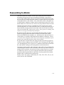
Reassembling the Monitor . . . . . . . . . .
Sealing the Monitor . . . . . . . . . . . . . .
Flat Panel Display Integration . . . . . . . . .
Where to Go from Here . . . . . . . . . . . .
9
Configure the Controller . . . . . . . . . . . 13
Connect the Controller . . . . . . . . . . . 13
.
.
.
.
.
.
.
.
.
.
.
.
.
.
.
.
.
.
20
20
20
21
22
22
23
23
24
24
25
26
27
28
32
34
35
36
.
.
.
.
.
.
.
.
.
.
.
36
37
39
41
41
42
44
45
46
47
47
Appendix A
Troubleshooting Guide
PC-Bus Controller . . . . . . . . . . . . . . 15
Contents . . . . . . . . . . . . . . . . . 15
Installation . . . . . . . . . . . . . . . . 15
The Troubleshooting Process . . .
Display Problems . . . . . . . . .
Software Troubleshooting . . . . .
Video Alignment Problems. . .
Hardware Troubleshooting . . . .
Touchscreen Diagnosis . . . .
Touchscreen Simulation . . . .
Serial Controller . . . . . . . .
Using the COMDUMP Utility
Configure the Controller . . . . . . . . . . . 15
Install the Controller in Your PC and Connect
the Touchmonitor . . . . . . . . . . . . . 15
Touchscreen Application Tips . . . . . . . . . . 16
Where to Go from Here . . . . . . . . . . . . . 18
.
.
.
.
.
.
.
.
.
49
.
.
.
.
.
.
.
.
.
.
.
.
.
.
.
.
.
.
.
.
.
.
.
.
.
.
.
.
.
.
.
.
.
.
.
.
.
.
.
.
.
.
.
.
.
.
.
.
.
.
.
.
.
.
49
50
50
51
51
53
55
57
57
E271-2210 Controller Protocol . . . . . . . 58
ix
E281A-4002 Controller Protocol . . . . . . 58
E271-140 Controller Protocol . . . . . . . . 58
E261-280 Controller Protocol . . . . . . . . 58
Using the TOUCHES Utility . . . . . .
RS-232 Connections . . . . . . . . .
Power Supply . . . . . . . . . . . . .
Bus Controller . . . . . . . . . . . . . .
Using the BUSSTAT Utility . . . . . .
Touchscreen Cables . . . . . . . . . . .
P/N 454173-000 Cable . . . . . . . .
Transient Protection Components . . . .
Diagnostic LEDs . . . . . . . . . . . . .
2210 Serial Controller. . . . . . . . .
3000U USB Controller . . . . . . . .
2201 PC-Bus Controller. . . . . . . .
Diagnostic Codes . . . . . . . . . . . .
DB9 and DB25 Connector Pin Positions .
.
.
.
.
.
.
.
.
.
.
.
.
.
.
.
.
.
.
.
.
.
.
.
.
.
.
.
.
.
.
.
.
.
.
.
.
.
.
.
.
.
.
.
.
.
.
59
59
61
62
62
63
63
64
64
64
65
65
66
67
Appendix B
Controller Configuration
General Information . . . . .
Jumper Settings . . . . .
2210 Serial Controller . . . .
Jumper Settings . . . . .
2210 Emulation Modes
3000U USB Controller. . . .
2201PC-Bus Controller . . .
Jumper Settings . . . . .
2201Emulation Modes
.
.
.
.
.
.
.
.
.
.
.
.
.
.
.
.
.
.
.
.
.
.
.
.
.
.
.
.
.
.
.
.
.
.
.
.
69
.
.
.
.
.
.
.
.
.
.
.
.
.
.
.
.
.
.
.
.
.
.
.
.
.
.
.
.
.
.
.
.
.
.
.
.
69
70
71
72
73
73
73
74
75
Appendix C
Specifications
77
Appendix D
Elo Part Numbers
Glossary
81
85
Index
91
x
List of Figures
AccuTouch Touchscreen . . . . . . . . . . . .
USB Controller Installation . . . . . . . . . . .
External Serial Controller Installation . . . . . .
PC-Bus Controller Installation . . . . . . . . .
Typical AccuTouch Touchscreen Installation (for
use with external controller) . . . . . . . .
Bezel design . . . . . . . . . . . . . . . . . .
Rear View of an AccuTouch Touchscreen with
Mounting Materials . . . . . . . . . . . .
Side View of an AccuTouch Touchscreen
Installation . . . . . . . . . . . . . . . . .
Touchscreen Cabling System for Internal Serial
Controller . . . . . . . . . . . . . . . . .
AccuTouch Touchscreen Simulation Circuits . .
Tabletop Controller Power Supply Cable
Connector . . . . . . . . . . . . . . . . .
Transient Protection Circuit . . . . . . . . . . .
DB9 and DB25 Connector Pin Positions . . . .
SmartSet Controller Jumper Settings . . . . . .
E271-2210 Serial Controller . . . . . . . . . .
E271-2201 PC-Bus Controller . . . . . . . . .
.6
12
14
16
21
22
30
35
36
56
61
64
67
70
71
73
xi
xii
CHAPTER
1
INTRODUCTION
CHAPTER 1
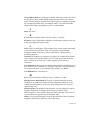
Introducing Touchscreens
Touchscreens are the ultimate operator/machine interface. In a touchscreen
system, you touch what you see. The computer responds. The human action and
the computer's reaction is simple, direct, and natural. Using touchscreens,
workers can control complicated processes. People who have never used a
computer before can interact easily with a touchscreen-based system.
Touchscreens bring the power of the computer within reach—in airports,
factories, shopping malls, schools, and hospitals.
Applications for touchscreens include:
• Public Information Systems
• Multimedia
• Retail and Point-of-Sale
• Process Control
• Instrumentation
• Gaming
• Ticket and Lottery
• Simulation and Training
• Education
The AccuTouch® Model:SCN-AT (E274) touchscreen product line is based on
patented resistive technology. The AccuTouch touchscreen has gained a
worldwide reputation for fast, responsive accuracy and reliability. It has an
unmatched combination of performance, size, and environmental adaptability.
1-1
Because of its many unique features, the AccuTouch touchscreen is ideally
suited for retail and restaurant point-of-sale, medical, instrumentation, and
process control applications. In fact, the AccuTouch touchscreen is used in
more applications than any other touchscreen.
Driver Software
Elo driver software provides a consistent software interface among all Elo
touchscreens and controllers.
The driver software scales the absolute coordinates received from the
touchscreen controller into translated screen coordinates, using the calibration
points obtained with the video alignment program included with the driver
software. The driver also performs other operations as directed by the
application.
Elo provides driver programs for the DOS, Windows 3.1, Windows CE,
Windows 95/98, Windows NT, Windows 2000, OS/2, and Macintosh operating
systems. Additional drivers are also available. Additional operating systems are
supported through outside sources. Refer to the Elo web site,
www.elotouch.com, for details.
If you cannot use an available driver, Elo can supply all the touchscreen related
information you will need to write your own driver for any type of system,
including UNIX workstations, real-time systems, and embedded systems. For
the 2500S controller, the SmartSet™ Touchscreen Controller Family Technical
Reference Manual which is available on the Elo web site, provide information
on this process. Machine-independent source code is included on a companion
disk and web site, www.elotouch.com.
Shipping Damage
If you notice damage to the shipping carton, or concealed damage, be sure to
save all packing materials for later inspection by the carrier, who is responsible
for any shipping damage.
If failure occurs during the warranty period, see the Limited Warranty section at
the beginning of this manual for instructions.
Care and Cleaning
Handle the touchscreen with reasonable care when not integrated into a monitor.
Do not pull or stress the cables.
1-2
Elo Entuitive Touchmonitor
Clean the touchscreen with Isopropyl 99% and lint free wipes. Always dampen
the wipes and then clean the touchscreen.
For operating and storage specifications, refer to Appendix C.
1-3
Elo Entuitive Touchmonitor
1-4
Elo Entuitive Touchmonitor
CHAPTER
2
ABOUT ACCUTOUCH TOUCHSCREENS
CHAPTER 2
Introduction
The Elo AccuTouch touchscreen system consists of a touchscreen and an
electronic touchscreen controller. The AccuTouch touchscreen is based on
patented resistive technology. The touchscreen may be a flat, spherical, or
cylindrical and is installed over the face of the display. Since its shape matches
that of the display face, an AccuTouch touchscreen has excellent clarity and
minimal parallax.
AccuTouch features include:
• Proven resistive technology.
• High accuracy and fast response.
• Hard-coated surface for scratch protection.
• Clear finish for maximum image clarity, or antiglare finish for reflection
control.
• Pressure-activated by a finger, fingernail, gloved hand, or any stylus.
• Large selection of standard sizes for spherical, and flat displays.
• Custom sizes for OEM quantities.
• Easily sealed to enclosure for harsh environment protection.
• Operates even when wet.
2-5
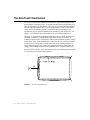
The AccuTouch Touchscreen
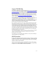
The AccuTouch resistive touchscreen consists of a glass panel molded to the
precise shape of a display's face. A scratch-resistant, hard-coated plastic cover
sheet is suspended over the surface of the glass by less than one-thousandth of
an inch with tiny separator dots. The cover sheet may be clear for best image
clarity or have an antiglare finish. For optimum optical performance, the
touchscreen may be optically bonded to the cathode ray tube (CRT) face. See
figure 2-1 for details on the construction of an AccuTouch touchscreen.
The glass is coated with a transparent uniform resistive coating, and the cover
sheet has a conductive coating. With a light touch on the cover sheet, the
conductive inner surface of the plastic makes contact with the resistive coating
on the glass. There is an electrical drive connection to each of the four corners
of the resistive coating, and a pickup connection to the coating on the cover
sheet. When the proper DC voltages are applied to the drive connections, the
voltage at the pickup connection is proportional to the position of the touch.
Refer to the Elo web site, www.elotouch.com, for more information on how the
AccuTouch resistive touchscreen operates.
Figure 2.1
2-6
AccuTouch Touchscreen
Elo Entuitive Touchmonitor
The logical sequence of operation of an AccuTouch controller, used in
combination with the AccuTouch touchscreen, is as follows:
1 When the controller is waiting for a touch, the resistive layer of the
touchscreen (the coating on the glass) is biased at +5 Vdc through all four
drive lines, and the cover sheet is grounded through high resistance. When
the touchscreen is not being touched, the voltage on the cover sheet remains
at zero. The voltage level of the cover sheet is continuously converted by the
analog to digital converter (ADC) and monitored by the microprocessor on
the controller. When the touchscreen is touched, the microprocessor detects
the rise in the voltage of the cover sheet and begins coordinate conversion.
2 The microprocessor places the X drive voltage on the touchscreen by
applying +5 Vdc to Pins H and X and grounding Pins Y and L.
3 An analog voltage proportional to the X (horizontal) position of the touch
appears on the cover sheet at Pin S of the touchscreen connector. This voltage
is then digitized by the ADC and subjected to an averaging algorithm, then
stored for transmission to the host.
The averaging algorithm reduces noise resulting from contact bounce during
the making and breaking of contact with the touchscreen. Successive X
coordinates are tested to determine that their values differ by no more than a
certain range. If one or more samples fall outside this range, the coordinates
are discarded and the process is restarted. This is continued until several
successive X coordinates fall within the range. The average of these values is
used as the X coordinate.
4 Next, the microprocessor places the Y drive voltage on the touchscreen by
applying +5 Vdc to Pins H and Y and grounding Pins X and L.
5 An analog voltage proportional to the Y (vertical) position of the touch now
appears on the cover sheet at Pin S of the touchscreen connector. This signal
is converted and processed as described above for the X position.
6 Successive coordinate pairs are sampled to eliminate the effects of noise. If a
sample does not fall within an internal range, all X and Y coordinates are
discarded and the X sequence is restarted at step 2.
7 Once acceptable coordinates have been obtained, an average coordinate is
determined and communicated to the host processor.
The X and Y values are similar to Cartesian coordinates, with X increasing
from left to right and Y increasing from bottom to top. Z increases with touch
pressure. These absolute coordinates are arbitrary and unscaled, and will vary
slightly from unit to unit. Any coordinate normalization or scaling must be
done at the driver level, and calibration to the display image must be
performed for each unit. Because of the stability of the AccuTouch system,
recalibration is not necessary unless the position of the image changes.
2-7
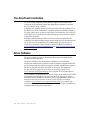
The AccuTouch Controllers
The AccuTouch controllers provide the drive signals for the touchscreen,
convert the received analog signals into digital touch coordinates, and send
these coordinates to the computer.
Controllers are available for the AccuTouch touchscreen with serial RS-232 or
PC-Bus (ISA or EISA compatible). Controller options are detailed in Chapter 3.
For large-volume users, it may be cost-effective to integrate the Elo COACH™
and COACH IIs (Controller On A CHip) directly into your board-level design.
Contact Elo for details.
Resolution and performance of the AccuTouch system are defined by the
controller. Unscaled coordinate ranges are about 400-3800 for X and 600-3500
for Y, with over 200 coordinates per second possible. See the SmartSet™
Touchscreen Controller Family Technical Reference Manual available at
www.elotouch.com/support/dwnldmnls.asp and www.elotouch.com/products/
accutec/c3000u.asp.
Driver Software
Elo driver software provides a consistent software interface among all Elo
touchscreens and controllers.
The driver software scales the absolute coordinates received from the
touchscreen controller into translated screen coordinates, using the calibration
points obtained with the calibration program included with the driver software.
The driver also performs other operations as directed by the application.
Elo provides driver programs for a variety of operating systems. Go to
www.elotouch.com/Support/dnld.asp for a complete list of available drivers.
If you cannot use an available driver, Elo can supply all the touchscreen related
information you will need to write your own driver for any type of system,
including UNIX workstations, real-time systems, and embedded systems. The
SmartSet Touchscreen Controller Family Technical Reference Manual
available at www.elotouch.com/support/dwnldmnls.asp, gives step-by step
instructions on this process. Machine-independent source code is included on a
companion disk along with a setup utility.
2-8
Elo Entuitive Touchmonitor
CHAPTER
3
TOUCHMONITOR INSTALLATION
CHAPTER3
Elo purchases and resells a variety of monitors, called Touchmonitors, both
CRT and LCD, with touchscreens and all related components fully installed. If
you are installing components rather than a touchmonitor, proceed to Chapter 4,
install your touchscreen components, then return to this chapter.
Touchmonitor Benefits
Touchmonitor benefits include:
• Single source for touchscreen and display.
• Professionally engineered touchscreen installation.
• UL,cUL, FCC, TÜV, CE, and other agency approvals.
• Elo warranty.
• Plug-and-play convenience.
Controller boards, cables, and power supplies may also be ordered separately.
3-9
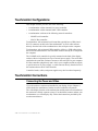
Touchmonitor Configurations
This chapter assumes you have one of the following:
• A touchmonitor with an internal 2210 serial controller.
• A touchmonitor with an internal 3000U USB controller.
• A touchmonitor with one of the following external controllers:
• 2210MX serial controller.
• 2201 PC-Bus controller.
Touchmonitors with an internal serial controller typically have a DB9 female
RS-232 connector on the back of the touchmonitor. A serial cable connects
directly from the back of the touchmonitor to the serial port on the computer.
Touchmonitors with an internal USB controller will have a USB cable exiting
the back of the touchmonitor. The USB cable connects directly to a USB port on
the computer.
The 2210MX serial controller is typically mounted on the back of the display
and uses either a keyboard power tap or external power supply. The serial cable
attached to the controller enclosure connects to the serial port on your computer.
PC-Bus controllers plug directly into a slot in your computer and do not require
a special enclosure or power supply. A cable connects directly from the back of
the touchmonitor to the PC-Bus controller.
Controller boards, cables, and power supplies may also be ordered separately.
Touchmonitor Connections
Connecting the Power and Video
If you do not have a touchscreen installed in your display, skip to Chapter 4,
which details the installation of touchscreen and controller components.
The video display function of the touchmonitor and the touchscreen installed on
the monitor are entirely separate systems. You should first connect and test your
touchmonitor as a video display only. Follow the instructions provided by the
monitor manufacturer.
3-10
Elo Entuitive Touchmonitor
Next, refer to the appropriate page to continue your installation:
Controller
Configuration
Page
2210
3000U
Touchmonitor with Internal Serial Controller
Touchmonitor with Internal USB Controller
11
12
2210
2201
2210MX External Serial Controller
PC-Bus Controller
13
15
Touchmonitor with Internal Serial Controller
Contents
This configuration includes a touchmonitor with an internal 2210 serial
controller and a serial cable. Actual configuration may vary due to third-party
integrations.
Installation
The 2210 controller is internal to the monitor and is shipped preconfigured for
use with Elo software.
Complete these steps:
1 Plug the DB9 male end of the supplied serial cable into the DB9 female
connector typically labeled "Touch Interface" on the back of the
touchmonitor case.
2 Plug the DB9 female end of this cable into the computer's DB9 serial port. If
you have a 25-pin serial port, use a DB9 male to DB25 female adapter.
Proceed to “Where to Go from Here” on page 3-18.
3-11
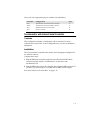
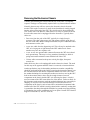
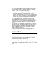
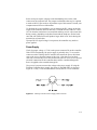
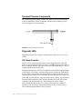
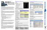
Touchmonitor with Internal USB Controller
Contents
This configuration includes a touchmonitor with an internal 3000U USB
controller.
Installation
Note:
You can leave your computer on when you connect to a USB port.
The 3000U USB controller is internal to the monitor and is shipped
preconfigured for use with Elo software.
Complete this step:
1 Plug the USB cable exiting the touchmonitor into a USB port on the
computer.
Proceed to “Where to Go from Here” on page 3-18.
Touchscreen
monitor
USB
connector
Video cable
Female 15-pin
video
connector
Figure 3.1
3-12
USB cable
USB Controller Installation
Elo Entuitive Touchmonitor
Monitor
power cable
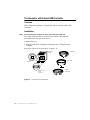
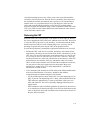
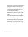
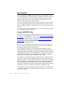
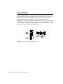
2210MX External Serial Controller
Contents
This configuration includes a 2210 serial controller in a small enclosure with a
keyboard power tap or external power supply and connecting cables.
Installation
Complete these steps:
1 Configure the controller
2 Connect the touchscreen controller and the supplied cables.
Configure the Controller
The controller is shipped preconfigured for use with Elo software. No changes
are necessary for most users. Specific settings and options available for your
controller are listed in Appendix B.
The 2210MX External Serial Controller is typically shipped configured at 9600
baud. If your software does not support the 2210 directly, you may operate the
2210 in E271-140, E261-280, or E281A-4002 emulation modes. See B for
jumper settings.
Additional technical information about the 2210 controller can be found in the
SmartSet Touchscreen Controller Family Technical Reference Manual,
available at www.elotouch.com/support/dwnldmnls.asp.
Connect the Controller
CAUTION
Before using a keyboard power tap, be sure sufficient power is available for the
touchscreen controller or damage may occur to the computer.
Before connecting a keyboard power tap to the controller, be sure that power to
the computer is OFF. Connecting a keyboard power tap to a powered computer
may seriously damage the computer or the controller.
Complete the following steps if you are using a keyboard power tap:
1 Two different keyboard power taps are available. Use Elo P/N 980773-000 if
you have a standard keyboard connector and Elo P/N 388923-000 if you have
a PS/2 keyboard connector.
2 Unplug the keyboard from the computer.
3 Plug the male connector on the Y end of the adapter cable into the keyboard
connector on the back of the computer.
3-13
4 Plug the keyboard cable into the female connector on the Y end of the
adapter cable.
5 Plug the other end of the adapter cable into the connector on the serial cable.
6 Plug the DB9F end of the attached serial cable into a serial port.
7 Proceed to “Where to Go from Here” on page 3-18.
Complete the following steps if you are using a wall mount power supply:
1 Two different wall mount power supplies are available. Use Elo P/N 580979-
000 if you are using this inside the United States and Elo P/N 319865-000 if
you are using this outside of the United States.
2 Plug the single male connector on one end of the power supply into the
connector on the serial cable.
3 Plug the other end of the power supply into a proper receptacle.
4 Plug the DB9F end of the attached serial cable into a serial port.
Proceed to “Where to Go from Here” on page 3-18.
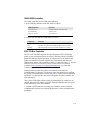
Video
cable
Male 9-pin
touchscreen
connector
Female 15-pin
video
connector
Figure 3.2
3-14
External serial
touchscreen
controller
External Serial Controller Installation
Elo Entuitive Touchmonitor
Touchscreen
cable
Controller
power supply
Touchscreen
monitor
Alternate keyboard
controller power cable
Monitor
power cable
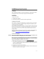
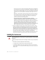
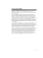
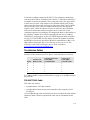
PC-Bus Controller
Contents
This configuration includes the 2201 PC-Bus controller and a touchscreen
cable.
Installation
Complete these steps:
1 Configure the controller.
2 Install the controller in your PC and connect the touchmonitor.
Configure the Controller
The controller is shipped preconfigured for use with Elo software. Except for
the Base I/O Port and Interrupt (IRQ) settings, no changes are necessary for
most users. Specific jumper settings and options available for your controller
are listed in Appendix B.
If your software does not support the 2201 directly, you may operate the
controller in E271-141 emulation mode. See B for jumper settings.
Additional technical information about the 2201 controller can be found in the
SmartSet Touchscreen Controller Family Technical Reference Manual,
available at www.elotouch.com/support/dwnldmnls.asp.
Install the Controller in Your PC and Connect the Touchmonitor
Complete these steps:
1 Discharge any static charge on your body by touching the back of the
computer cabinet.
2 Note the Base I/O Port for use with the driver software. Factory default
settings are 280 (hexadecimal) and no interrupt. (The driver software selects
the interrupt.)
3 Turn the computer off and unplug the AC power cord from the outlet.
4 Remove the computer's cover. Refer to the computer user's manual for
instructions.
5 Choose an available expansion slot.
6 Remove the screw holding the expansion slot's access bracket, then remove
the bracket.
3-15
7 Insert the touchscreen controller into the expansion slot. The controller
should seat fully into the slot and the access bracket should mate with the
frame of the computer.
8 Replace the access bracket retaining screw, insuring that the controller
remains seated in the socket.
9 Replace the computer's cover.
10 Plug the DB9 female end of the supplied touchscreen cable into the DB9
male connector labeled "Touchscreen Interface" on the back of the
touchmonitor case. Plug the DB9 male end of the touchscreen cable to the
DB9 female connector on the controller.
11 Plug the AC power cord back into the outlet and reboot the computer.
12 Proceed to “Where to Go from Here” on page 3-18.
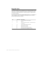
Touchscreen
monitor
Male 9-pin
touchscreen
connector
Video cable
Female 15-pin
video
connector
Figure 3.3
Touchscreen
cable
Monitor
power cable
PC-Bus
touchscreen
controller
PC-Bus Controller Installation
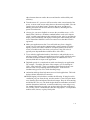
Touchscreen Application Tips
Sometimes a simple change to your application may mean the difference
between success and failure.
1 Windows applications should be run full screen-don’t display a title bar or
menu bar in kiosk applications.
2 Bright background colors (no black!) in your application will hide
fingerprints and reduce glare. Dithering or other patterned backgrounds, such
as a crumbled paper look, will help the eye focus on the screen image instead
of reflections, even in areas with no icons or menu choices.
3 Use a simple point-and click interface with large buttons. Do not use
dragging, double-clicks, scroll bars, drop-down menus, multiple windows, or
3-16
Elo Entuitive Touchmonitor
other elements that can confuse the user and interfere with usability and
efficiency.
4 Turn the cursor off—your user will focus on the entire screen instead of the
arrow. A cursor on the screen makes the user subconsciously think, “How do
I get the arrow to do what I want?” Remove the cursor, and the user’s
thinking and action will be direct instead of indirect, unlocking the true
power of touchscreens.
5 Always give your users feedback as soon as they touch the screen. A 3-D
button effect (similar to a Windows standard button) works well. Output a
“click” or other sound whenever they touch the screen. Also, be sure that the
display clears immediately and displays an hourglass while loading the next
screen. Immediate feedback is critical to reassure users that their touch is
registered.
6 Make your application run fast. Users will walk away from a sluggish
system, but you can keep their attention with a quick response to touches.
Speedy systems also reduce vandalism. (Graphics modes with excessive
colors or resolution only slow down your system, Using 256 colors is
typically more important than resolution above 640 x 480.)
7 Try to make the application intuitive; limit choices; and guide the user as
much as possible. Testing your application on focus groups will disclose the
areas that need improvement. If anyone pauses in confusion for even a
moment, think how to improve the application.
8 Digitized speech via a sound card can walk users through your application.
For example, “Touch the first letter of the company you are looking for.”
Click. “Now touch OK.” There is something almost magical about a user
interface with voice prompting and touch response. Your brain can
simultaneously process voice while absorbing image.
9 Animation and large fonts help attract users to kiosk applications. The kiosk
design (cabinet) should also be attractive.
10 When designing a kiosk cabinet, consider the following. If using forced air
ventilation, put your fan at the top, near the monitor’s vents. Keep the intake
away from the floor and airborne dust from footsteps. Keep air from entering
around the CRT face, too. The kiosk design should accommodate variation in
monitor dimensions and bezels, as monitor models may come and go every
few months. Remember to point your speakers in the direction of the user’s
ears. Finally, choose a finish that does not show fingerprints—avoid polished
stainless steel, chrome, or glossy black paint.
3-17
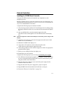
Where to Go from Here
The hardware installation is now complete.
Load the Elo driver specific to your operating system
If you will be writing your own driver program, see the SmartSet Touchscreen
Controller Family Technical Reference Manual available at
www.elotouch.com/support/dwnldmnls.asp for step-by-step instructions on this
process. Machine-independent source code is included on a companion disk
along with a setup utility.
3-18
Elo Entuitive Touchmonitor
CHAPTER
4
COMPONENT INSTALLATION
CHAPTER4
Elo purchases and resells a variety of monitors, called touchmonitors, with
touchscreens and all related components fully installed. If you already have a
touchmonitor, follow the installation instructions in Chapter 3.
If you do not have a touchmonitor, read this chapter for details on installing
touchscreen components that will convert your monitor into a touchmonitor.
Details are given on mounting the touchscreen, controller, and connecting
cables. While this chapter refers primarily to CRT-based monitor technologies,
much of this information can be applied to other monitor technologies. See “Flat
Panel Display Integration” on page 4-47.
These instructions assume you have purchased an Elo touchscreen installation
kit (P/N 458095-000), and a transient protection cable (PN 899389-000). Only a
minimum of equipment and materials is required beyond what is provided in the
kits.
In brief, adhesive materials are used to fasten the touchscreen to the CRT and
then the assembly is reinstalled in the original enclosure with minor
modifications. If this procedure is not suitable for mechanical, electrical, or
optical reasons, there are other techniques for touchscreen installation that may
achieve the desired results. These techniques often require specialized
equipment or materials, and a complete discussion is beyond the scope of this
manual. See “Installing the Touchscreen” on page 4-28.
4-19
Safety Information
WARNING:
The touchscreen installation procedure outlined in this chapter may require exposure to high-voltage components and handling of the CRT. This procedure can be
dangerous and an accident is potentially lethal. Therefore, the procedure should
only be performed by a qualified person. Read this entire chapter before attempting a touchscreen installation. Follow the procedure carefully, work with the power
off and the unit unplugged, observe all warnings, and wear protective clothing. Elo
is not liable for damage or injury that could result from your actions.
Consider purchasing a touchmonitor from Elo if you do not have previous
experience working with touchscreens and disassembling monitors. Elo also
offers touchscreen installation services for customers specified monitor.
Work Area
Before proceeding with the installation, prepare a padded work surface. A
plastic waste basket is recommended for supporting the CRT during part of the
installation.
Protective Clothing
Wear safety glasses, gloves, a rubber apron, and heavy protective clothing for
any portion of this procedure that involves handling or working near the CRT.
4-20
Elo Entuitive Touchmonitor
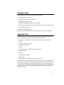
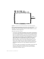
Getting Started
AccuTouch touchscreens can be installed on most types of monitors. Figure 4-1
shows a typical installation.
Figure 4.1
Typical AccuTouch Touchscreen Installation (for use with external
controller)
AccuTouch touchscreens are available for most monitors. Each monitor may
pose unique installation issues. Although your monitor may not be a standard
touchmonitor product from Elo, we may have had some experience with it.
Contact Elo Technical Support for more information.
This section assumes you have already determined compatibility between the
touchscreen and the monitor. A touchscreen installation kit is available from Elo
(P/N 458095-000), which includes the commonly used materials needed for
installation.
Most monitors require complete disassembly, including removal of the CRT, to
install a touchscreen. Disassembling the monitor can be a dangerous procedure
if done improperly. Before proceeding, review the rest of this chapter. Basic
assembly skills are required. Seek qualified help if you have any doubts about
your ability to complete the installation.
Any damage to the monitor or the touchscreen as a result of improper
installation is the installer’s responsibility.
4-21
Without prior approval of the monitor manufacturer, you will probably void the
monitor's warranty by disassembling it. Also, it will be necessary to recertify the
monitor and touchscreen system for regulatory agencies (such as FCC,
UL/CSA, TÜV, CE, etc.) if those certifications were originally present and need
to be maintained for your intended application. (Elo offers touchmonitors with
full agency approvals.)
Handle the touchscreen with care. Avoid excessive handling and stress on the
touchscreen cable.
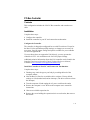
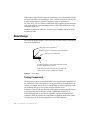
Bezel Design
The following graphic displays some bezel ideas in order to help you mount the
bezel to the touchscreen.
Bevel edge for nice appearance
Round corners for nice appearance and easy cleaning
Flat inner lip for sealing tape
On bezel and cabinet, choose paint finish and/or surface
texture so fingerprints do not show
Avoid tilt/swivel bases unless they are very stable - the
display should not move or shake when touched
Figure 4.2
Bezel design
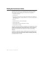
Testing Components
The display must be in good working order before beginning the installation of
the touchscreen. With a new display, it is suggested that you test the display by
running it overnight. Do not leave a constant image at normal brightness on the
screen during this test, as it may burn an image into the screen.
Familiarize yourself with the operation of the touchscreen and controller before
you proceed with the installation. Use the COMDUMP, BUSSTAT, or
TOUCHES programs as described in Appendix A to test serial and PC-Bus
controllers while the touchscreen components are arranged on the work surface.
Currently, there is no separate diagnostic test for USB controllers.
4-22
Elo Entuitive Touchmonitor
Installation Steps
The installation process consists of the following steps:
• Disassembling the monitor.
• Attaching the touchscreen to the CRT.
• Installing transient protection.
• Optionally installing an internal serial controller.
• Interfacing the touchscreen or serial data cables to the exterior of the monitor.
• Reassembling the monitor.
• Optionally sealing the monitor.
Specific compatibility may not be confirmed until well into the installation.
Suggested Tools
The following is a list of tools that may be needed to install the touchscreen.
Some of the tools are optional, but will be useful if needed.
• Long (at least 9 inches, 200 mm) flat blade screwdriver with insulated
handle.
• Clip lead or heavy-gauge wire.
• #2 Phillips screwdriver.
• Scissors.
• X-Acto knife (No. 11 blade) or hand milling tool.
• DB9 hole punch.
• Cable ties.
• Household glass cleaner.
• Paper towels.
• Small containers or plastic bags to hold loose parts.
The Elo Touchscreen Installation Kit (P/N 458095-000) is also recommended,
and includes commonly used materials needed for touchscreen installation. This
kit is useful for identifying preferred materials for your own procurement and
may also be cost-effective and convenient when purchased for a limited number
of installations. A copy of the monitor manufacturer’s service manual is also
useful, if available.
4-23
Disassembling the Display
Disassemble the monitor on a large, well-lit work surface. Leave space to set
aside major monitor components. Group screws and other hardware in small
containers or in specific areas on the work surface as you remove them, in
relation to the part of the monitor where you are working. If you complete the
installation process in one session (which may require several hours for your
first efforts), it is unlikely that you will have trouble reassembling the monitor.
Most monitor manufacturers connect the major components with detachable
cables that have labeled and keyed connectors; these cables are of lengths that
will usually connect to only one place. Also, screws are identifiable by type and
size, and usually will not fit in the wrong place. The most difficult problem with
missing or wrong hardware or connections will be with single ground cables
that attach to obscure ground points on the metal chassis. When in doubt, make
notes of the connection points.
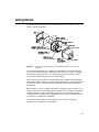
Removing the Back Case
Figure 4.1 on page 4-21, shows the typical construction of a 14-inch monitor.
Disassembly usually starts with removal of the back case. For assistance with
disassembly, consult your particular manufacturer's service manual. Carefully
lay the monitor on its face on the padded work surface and remove the screws
that attach the back case to the bezel or frame.
While removing the back case, note the clearance between the inside rear
surface of the case and a small circuit board plugged into a socket on the end of
the CRT. If there is not enough clearance to move the CRT and this circuit
board about 3/8-inch (9 mm) toward the rear of the case, you may be unable to
successfully install a touchscreen on the monitor and completely reinstall the
back case. Contact Elo Technical Support for possible alternatives.
After the back case is removed, the CRT is substantially exposed. Use extreme
care when working around the CRT.
WARNING:
4-24
Impact or force against the neck of the CRT, or the pins at the end where the small
circuit board is attached, could crack the tube, resulting in loss of vacuum or
implosion of the tube. Either result destroys the CRT. Implosion (collapse of the
glass inward, caused by the high vacuum inside the tube), followed by the
rebound of many glass pieces outward, is potentially lethal to anyone in the immediate area. Handle the CRT carefully, keep tools away from the CRT, and wear protective clothing including eye protection. See Safety Information, page 20.
Elo Entuitive Touchmonitor
Discharging the CRT
WARNING:
Dangerous voltages may be present on the CRT anode. The anode may retain a
very dangerous voltage even after the monitor has been off for days. Accidental
contact with the anode lead or anode button (the small hole in the CRT glass
where the anode lead is attached) prior to discharge may result in a potentially
lethal shock. Follow the procedure below carefully to avoid injury.
The anode lead of the monitor feeds high voltage from the flyback transformer
to the anode button on the CRT. The anode lead is usually red in color, and the
actual connection to the anode button is usually covered by a large rubber
suction cup-like boot. In most monitors, the button is located on the tapered
face, or bell of the CRT glass near the top of the monitor. See Figure 4.1 on
page 4-21.
It may be necessary to remove some sheet metal to gain access to the anode
lead—be very careful to do this without making contact to the anode lead itself.
Carefully discharge the CRT using the following procedure:
• Connect a clip lead or a heavy-gauge wire to chassis ground of the monitor
(or if the CRT is free-standing, the mounting ears or the spring-tensioned
ground strap).
• Connect the other end of the clip lead or wire to the stem of a flat blade
screwdriver that has an insulated handle.
• Hold the screwdriver by the insulated handle only. Insert the blade of the
screwdriver under the rubber boot and make contact with the anode lead at
the button. A distinct “snap” may or may not be heard as it discharges,
depending on the amount of charge present on the anode.
• Disconnect the anode lead from the button by unhooking the spring wire
clips. Note the location of the anode for proper CRT orientation during
reassembly.
WARNING:
The CRT will regain a charge over time, even after it has been discharged. To avoid
a dangerous electric shock, always discharge the CRT just before handling it, and
treat it with respect thereafter.
4-25
Removing the Electronics Chassis
Continue disassembling the monitor until the face of the CRT is completely
exposed. The degree of disassembly required will vary from monitor to monitor.
Normally the next step will be to remove the electronics chassis from the
monitor. This requires removal of a small circuit board that is usually plugged
into the socket on the end of the CRT. The circuit board is often glued to the
CRT socket with a soft adhesive which must be cut away to remove the board.
Several cables must also be unplugged from the electronics. Typically these
cables are:
• Four wires from the yoke of the CRT, typically in a single four-pin
connector. The yoke is the copper wire and magnet assembly at the base of
the neck of the CRT. MPR II-compliant monitors may have additional cables
and connectors on the yoke.
• A two-wire cable from the degaussing coil. This coil may be attached to the
CRT, or be laying out of sight between the CRT and the bezel. Some
monitors may have two separate coils.
• A one- or two-wire ground cable connected between the CRT circuit board
and a ground strap. This strap is a long, annulated, braided wire which is
spring tensioned to maintain contact with the bell of the CRT.
• Various cables connected to the power switch, pilot light, front panel
controls, etc.
Other cables may have to be unplugged from the electronics chassis. The need
for this may not be apparent until the chassis is removed, as instructed below.
Another preliminary step in determining touchscreen-monitor compatibility
should be performed at this point. Before removing the electronics chassis, note
the clearance between the chassis components and the bell of the CRT. Since
the standard technique for mounting the touchscreen involves moving the CRT
back in the monitor chassis, there must be enough clearance between
components on the chassis and the CRT after allowing for about 1/4-inch (6
mm) movement of the CRT towards the rear of the chassis. Failure to allow for
this clearance requirement may result in mechanical damage later (especially in
shipping). It may also cause electrical damage from shorts between "live"
components on the chassis, such as heat sinks or uninsulated component leads,
and the bell of the CRT which is usually painted with a conductive coating that
is grounded to the chassis through the braided wire ground strap. Repositioning
or substituting low profile components may be an option. Contact Elo Technical
Support for assistance (1-800-557-1458 x6).
4-26
Elo Entuitive Touchmonitor
After disconnecting any necessary cables, remove the screws that attach the
electronics chassis to the bezel. Note the bezel is essentially where all parts of
the mechanical assembly are attached, unless you have a rare unit that has an
internal frame. As you pull the chassis away from the bezel, make sure that
cables and circuit boards do not hit the neck of the CRT and that nothing
becomes caught on the adjustment rings or other components on the neck of the
CRT. Also watch for other cables that need to be disconnected. After removal,
set the electronics chassis aside.
Removing the CRT
Removal of the CRT is next. Prepare a soft surface to set the CRT on. Remove
the screws attaching the CRT to the bezel, and then remove the CRT. Do not lift
or carry the CRT by the neck or yoke assembly. Avoid contact with the anode
button, which may still have some residual charge on it, (you may wish to
discharge it again at this point). Set the CRT on the prepared surface.
Several other preliminary compatibility requirements should now be assessed:
• Position the CRT so the face is accessible, providing a soft cushion for the
neck and the yoke if they must rest on the work surface. Alternatively, set the
CRT face-up in an office-type plastic waste basket, making sure that the tube
is not resting on the neck (The small part of the CRT is the neck). Place the
touchscreen on the face of the tube, and check to see that the face of the CRT
and touchscreen are about the same size, and that the radius of curvature
(ROC) of each surface matches well. If both of these conditions are not met,
you may not have the proper touchscreen for the monitor. Most color
monitors have standard size CRT's with standard ROC's, and Elo has
touchscreens for most of them.
• N ext, determine if the touchscreen will fit in the bezel without modifications
to the bezel. Modifications, if necessary, should be done without
compromising the mechanical integrity of the monitor.
• Lay the touchscreen face-down in the bezel. Leave the degaussing coil in
place, if present. The degaussing coil is a hoop, often located between the
CRT and bezel, approximately 1/4-inch (6 mm) thick, with a two-wire
cable and connector. The coil was probably unplugged from the power
supply earlier.
• If the touchscreen will not fit flush against the lip of the bezel, do not force
it. An interference fit between the edge of an AccuTouch touchscreen and
some of the plastic ribs found in monitor bezels could result in fracture of
the glass after reassembly.
4-27
• It may be necessary to cut the ribs and struts inside the bezel. Cutting these
ribs and struts does not usually cause difficulties, although the stiffness of
the bezel may be reduced slightly. Try not to cut into the posts for the CRT
attachment screws. Bezel and tube combinations that require this cut are
rare.
• Generally, a total clearance between the edge of the touchscreen and any
ribs or struts of at least 1/4-inch (6 mm) in both axes is necessary. This
prevents the interference fit problem discussed above and allows for
variation in touchscreen mounting position.
• The potential interference between the degaussing coil and the
touchscreen must also be evaluated. The coil will usually fit between the
touchscreen and the inside surface of the bezel, as there is typically a
natural cavity for it. If there is not enough space for the coil, you may have
to provide additional setback for the CRT. It may also be possible to
relocate the coil to the bell side of the CRT. Normally, this does not
significantly reduce the coil’s effectiveness. However, you must determine
this by inspecting the monitor for color problems after reassembly.
1 Check for adequate clearance of the cable from the bezel structure. If the
position of the cable causes difficulty, the touchscreen may be rotated 180°
only if the touchscreen is sealed and Elo drovers are used. The preferred
orientation of the AccuTouch touchscreen is with the cable exiting from the
left side, when viewed from the front of the monitor. Rotation will cause an
inversion of the output coordinates, which will be compensated for
automatically by Elo driver software, but perhaps not by other drivers. (Flat
touchscreens should have the plastic surface on the side facing the user.)
Installing the Touchscreen
CAUTION:
After the touchscreen is attached to the CRT, transient protection must be in place
before applying power to the monitor. Transient protection is discussed on
page 4-34.
When preparing the touchscreen for mounting to the CRT, major considerations
are:
• Reasonable mechanical alignment with the display.
• A complete dust seal between the touchscreen and the CRT.
• A mounting technique that evenly supports the touchscreen on at least two
opposite edges. Elo recommends double-sided tape between the touchscreen
and the CRT.
4-28
Elo Entuitive Touchmonitor
• Creating enough space between the CRT and the bezel to accommodate the
touchscreen. Adequate spacing can normally be accomplished by:
1 trimming or milling the inside of the bezel
2 using spacers to move the CRT back in the chassis
3 using spacers to move the bezel away from the touchscreen.
A combination of moving the CRT back with spacers and trimming the bezel
is the usual solution.
• Depending on the touchscreen selected, avoidance of contact between the
display bezel and the active area of the touchscreen may be necessary. The
active area is that portion of the touchscreen inside the solid line. This "line"
can be easily seen on the touchscreen itself as the edge of a piece of
translucent material which is between the touchscreen glass and cover
sheet.A small force applied to the cover sheet in the active area will produce
contact between the glass and cover sheet registering a touch. A permanent
touch, such as one produced by a bezel, will defeat the normal operation of
the touchscreen. (It is permissible for the display bezel or a gasket to make
permanent contact with the inactive border region of the touchscreen, and
this often produces a more attractive solution.) Some AccuTouch
touchscreens are sized so the active area is larger than typical bezel openings,
so bezel contact often produces a touch.
Some of the popular touchscreen sizes are available with a wider inactive
border region. This will allow you to install the touchscreen with the display
bezel in contact with the touchscreen. The factors you should consider when
selecting this installation method are:
• Spacer Selection - Spacers between the bezel and CRT cannot be
eliminated using this method, and in fact should be chosen carefully. The
desired result is to have the bezel just touch the touchscreen, but put little
or no pressure on it.
• Sealing - Sealing touchscreens in the inactive border region will be easier.
Caulks and gaskets of almost any type may be used to make a seal between
the touchscreen and bezel in this region.
Double-sided tape and foam sealing tape are included in the Elo touchscreen
installation kit (P/N 458095-000). The following steps assume you will use
these materials to mount the touchscreen to the CRT.
4-29
Figure 4.3
Rear View of an AccuTouch Touchscreen with Mounting Materials
Before mounting the touchscreen, clean the face of the monitor and the back of
the touchscreen with household glass cleaner. Be sure to remove all
fingerprints. The space between the touchscreen and the monitor face must be
clean and free of any foreign objects.
Mount the touchscreen as follows:
• Use two layers of the double-sided adhesive tape to achieve a total thickness
of 1/16-inch (2 mm). While specific touchscreen and CRT combinations may
allow the use of thinner materials, 1/16-inch (2 mm) is generally necessary to
allow for variations in ROC between the two glass surfaces. Review the fit
between the touchscreen and the CRT before applying the tape. If one pair of
opposite edges has a closer fit than the other, put the adhesive tape on the
edges of the touchscreen with the better fit. See figure 4-2 for typical
placement. If there is a good fit on all four edges, you may want to use
double-sided adhesive tape on all four edges. When doing this, move the
adhesive tape in slightly on one pair of edges and add foam sealing tape
outside these two edges. The thicker foam tape will keep the adhesive tape
away from the CRT until you are ready to adhere the touchscreen to the
monitor.
In general, the adhesive tape should be set back slightly from the edge of the
active area of the touchscreen. When the monitor is reassembled, the
mounting tape should not be visible. Do not remove the liner from the
exposed side of the adhesive tape yet.
4-30
Elo Entuitive Touchmonitor
• Cut and place the foam sealing tape on the back of the touchscreen to form a
dust seal as shown in Figure 4.2 on page 4-22. This seal is particularly
important because the CRT is a good electrostatic precipitator and will attract
dust. The adhesive tape and foam sealing tape should form a complete seal
around the touchscreen. Do not leave any gaps. The sealing tape should not
be visible when the monitor is reassembled.
• Practice aligning the touchscreen on the CRT without removing the adhesive
tape liner. The installation can tolerate some horizontal and vertical shift.
However, rotational skew between the touchscreen and monitor axes cannot
be easily compensated for in the calibration, and will also interfere with
proper mounting of the tube in the bezel.
• When you have a good feel for the placement of the touchscreen, clean the
back side of the touchscreen and the face of the CRT again. Avoid all contact
between the cleaning solution and the mounting materials as the cleaner may
cause the mounting materials to eventually release from the glass. Remove
all lint with a brush or compressed air. Remove the liner from the adhesive
tape and align the touchscreen on the monitor. The thicker foam tape will
keep the adhesive tape away from the CRT until you are ready to adhere the
touchscreen to the monitor. Now press the touchscreen firmly against the
CRT.
• Inspect your results carefully for alignment, trapped dust or lint, and a good
seal between the touchscreen and CRT. If there is trapped lint, you may be
able to remove it without removing the touchscreen by capturing it with a
thin wire with a small spot of glue. Poke the wire through the foam gasket
and stick the lint to the wire. Pull the lint back into the gasket and embed it
there, or remove it completely and reseal the gasket.
• If you must remove the touchscreen from the CRT, cut the adhesive tape
away with a sharp thin blade, such as an X-Acto knife. The touchscreen glass
will probably break if you try to pull it off by a corner or an edge. Shave the
old adhesive tape from the touchscreen and CRT with the knife. Adhesive
residues can be removed with isopropyl alcohol, which will leave streaks and
fingerprint smears. Use glass cleaner for the final cleaning prior to
reapplication of new tape.
4-31
Spacing the CRT from the Bezel
The last part of the touchscreen mounting procedure is to determine the
appropriate spacing of the CRT from the bezel, (with the touchscreen attached),
and to reinstall the CRT with the required spacers in place (refer to, Figure 4.1
on page 4-21.) Do not clamp the touchscreen between the bezel and the CRT
without proper spacers as breakage will almost certainly occur. The nominal
thickness of the touchscreen and the two layers of adhesive tape is 3/16-inch
(5 mm). If your installation has a 1/8-inch (3 mm) touchscreen-to-bezel gap,
5/16-inch spacers would be required. If the touchscreen is to be in contact with
the bezel, 3/16-inch (5 mm) nominal spacers would be required.
Because the original CRT face-to-bezel mount is often an interference fit, with
the bezel shape altered slightly to draw it up tightly against the CRT, you should
start with a 1/16-inch (2 mm) thicker spacer than the nominal dimension above.
Two thicknesses of spacers, plus additional washers to use as shims, are
available in the Touchscreen Installation Kit (458095-000).
During the spacer selection process, you may have to install the CRT with the
touchscreen attached in the bezel several times. To prevent the CRT from
dislodging the spacers, temporarily insert plastic tie wraps or toothpicks as
guides in the mounting post holes. After selecting the correct spacers, discard
the guides and fix the spacers more securely in place with the adhesive
"doughnuts" provided in the Touchscreen Installation Kit.
When spacers for the desired gap have been selected, install the CRT. Make
sure you have previously reinstalled the degaussing coil. Select a screw that is
long enough to compensate for the spacer thickness (provides at least three full
turns into the mounting post threads) but not so long as to penetrate the surface
of the bezel. Over-tightening the screws may strip or split the mounting posts.
After the screws have been tightened snugly, examine the clearance between the
bezel and touchscreen. Try to adjust for the clearances suggested unless the
available space is insufficient.
If you are trying for zero clearance between the touchscreen and the monitor
(using a wider inactive region touchscreen), the above process should still be
generally followed. Do not clamp the touchscreen between the bezel and the
CRT with no spacers as breakage will almost certainly occur.
Evaluate the bezel to touchscreen fit carefully. Before selecting spacers, check
the fit by placing the bezel over the touchscreen/CRT combination (using the
plastic waste bucket to hold the CRT), or gently setting the touchscreen/CRT
combination on top of the inverted bezel on the workbench. Look for reasonably
even fit. If the bezel in its relaxed state has a different curvature than the
touchscreen, this method may not work, and you may want to complete the
installation with a gap between the touchscreen and bezel as described earlier.
4-32
Elo Entuitive Touchmonitor
Select spacers to allow the touchscreen to just touch the bezel. If the bezel is in
contact in some areas and not in others, be wary of warping the bezel to achieve
uniform contact by using thinner spacers. While mounting tape will provide
some compliance and the touchscreen may also flex slightly, shipping damage
may occur.
4-33
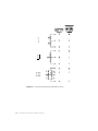
Transient Protection
WARNING:
Lack of transient protection may produce a dangerous shock hazard. Touchscreen
damage resulting from transient discharge is not covered by the Elo warranty.
Procedures discussed in this section must be followed to maintain safety and
assure reliability of the touchscreen system.
When an AccuTouch touchscreen is installed on a monitormonitor, the
combination becomes a capacitor which stores an electric charge. The simplest
capacitors are parallel plates of conductive material separated by an insulating
material called the dielectric. In this case, the plates are the metallized coatings
of the touchscreen and the CRT face, and the dielectric consists of the various
air and glass layers between them. See Figure 4.3 on page 4-30 . The
capacitance increases with the size of the plates and closer spacing.
The potential on the inside face of the CRT can be more than 30,000 volts.
When the monitor is turned on or off, a large difference in charge builds up
between the two plates (mainly C1 in Figure 4.3 on page 4-30 ). To balance the
charge, some current must flow from the system ground to the touchscreen. If
this current does not flow, the potential on the touchscreen rises until sufficient
potential exists to cause an arc. This arc can damage the touchscreen or cause a
dangerous electrical shock. Transient protection provides a safe, controlled path
for this current by limiting the voltage buildup on the touchscreen.
Elo recommends connecting the cathodes of four transient suppression diodes to
the four glass substrate terminals of the touchscreen. Make the connection as
close to the touchscreen as possible. The anode end of all four diodes must be
attached to the CRT chassis ground through a short wire of the largest possible
diameter (16 gauge or heavier recommended). See Figure A.3 on page A-64, for
a circuit diagram.
In monitor installations where the touchscreen controller will be external to the
monitor, use the Elo transient protection cable (899389-000), included with the
touchscreen kit. You must attach the transient protection component(s) to the
touchscreen cable and connect the ground wire to the monitor’s chassis ground
before turning the monitor on. The controller need not be connected to the
touchscreen.
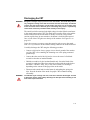
In monitor installations where the touchscreen controller will be installed
internal to the monitor, the serial controller’s on-board transient protection may
be used. The touchscreen must be connected to the controller and controller
grounded through one of the plated-through mounting holes before turning the
monitor on.
Some form of transient protection must be connected at all times. If you cannot
use one of the recommended solutions, contact Elo Technical Support for
alternatives.
4-34
Elo Entuitive Touchmonitor
Figure 4.4
Side View of an AccuTouch Touchscreen Installation
Controller Interface Options
Elo offers PC-Bus and serial (RS-232) controllers for AccuTouch touchscreens.
The serial controller may be purchased in a Tabletop enclosure (see Chapter 3)
or as components. This section includes a procedure for installing a CTR221000-AT-SER serial controller inside the monitor.
Regardless of the configuration of touchscreen and controller, you are
responsible for any recertification for agency approvals (FCC, UL/CSA, TÜV,
CE, etc.) that may be necessary for your application.
4-35
Internal Controllers
An AccuTouch internal controller mounting kit is available from Elo. P/N
734849-000 is for use with 2210 controllers. P/N 310900-000 is for use with
3000U controllers. These kits are useful together with the touchscreen
installation kit (P/N 458095-000) for identifying preferred materials for your
own procurement. The controller mounting kit may also be cost-effective and
convenient when purchased for a limited number of installations.
Figure 4.5
Touchscreen Cabling System for Internal Serial Controller
2210 Serial Controller and 3000U USB Controller
The mounting holes of the 2210 serial controller and the 3000U USB controller
are sized for 0.156-inch (4mm) snap-in standoffs. All AccuTouch touchscreens
have a cable termination that mates directly with the male header (P3) on the
controller. See Appendix B for specific mounting dimensions and connections.
Mounting an internal serial controller presents some challenges:
• Space for the controller and the cable headers, and for any additional
shielding that may be required to prevent noise and crosstalk between the
monitor and the controller. Noise can cause instability in the touch data or
other forms of intermittent operation.
4-36
Elo Entuitive Touchmonitor
• Space for an internal +5 Vdc power supply if required. The 2210 controller
power requirements are: 65 mA @ +5Vdc ± 10% standby, 160 mA average
with touch, 240 mA peak. Elo offers a 100 to 240 Vac international power
supply (P/N 742067-000) for use with the AccuTouch serial controller. The
3000U USB controller does not require a power supply as it gets its power
from the USB bus. See the SmartSet Touchscreen Controller Family
Technical Reference Manual available at www.elotouch.com/support/
dwnldmnls.asp for specific power requirements and connections for the 2210
controller and www.elotouch.com/products/accutec/c3000u.asp for specific
power requirements and connections for the 3000U controller.
• Cable routing that may contribute to noise and crosstalk.
• Electromagnetic Interference (EMI) suppression. Installing a touchscreen
and controller will affect the EMI characteristics of the monitor.
• Heat dissipation. The 3000U controller dissipates about 0.25 watt. The 2210
controller dissipates about 0.3 watt. A typical power supply, if required, may
dissipate several watts more. This places an additional load on the cooling
system of the display. The available locations to mount a controller and
power supply may also affect the cooling system of the display.
Both the serial and USB controller have transient protection on-board.
Mounting the controller internally is the only instance where this on-board
transient protection can be substituted for the transient protection solutions
discussed in the previous section. When using the on-board protection, you must
insure that the touchscreen is connected to the controller and the controller is
grounded when cycling power to the display. The 2210 has two plated-through
mounting holes, and its on-board transient protection is grounded through them.
The 3000U has four plated-through holes, and its on-board transient protection
is grounded through them. You must connect chassis ground to at least one of
these plated-through holes.
Installing the 2210 Serial Controller
Complete these steps to install the 2210 controller, using the internal controller
mounting kit (P/N 734849-000):
1 Be sure all controller jumper settings are made prior to installation. See
Appendix B.
2 Once proper component positioning has been determined, insert the desired
profile standoffs into at least three of the mounting holes, but do not peel off
the adhesive backing. Wait until some of the following steps are
accomplished:
4-37
3 Enable the controller’s on-board transient protection. This may be
accomplished one of two ways:
• If the controller can be mounted to a metal chassis, it can be grounded
through one of the plated-through mounting holes by using one of the No.
6 sheet metal screws and spacers provided in the kit. Use either of the
holes marked "PTH" in Figure B.2 on page B-71 .
• If the controller cannot be mounted to a metal chassis, use a ground wire
with a lug attached to connect one of the controller's plated-through
mounting holes to chassis ground.
When using the controller’s on-board transient protection, you must ensure that
the touchscreen is connected to the controller and the controller is grounded
when cycling power to the monitor.
1 Connect the power cable harness to the 1x2 male connector at P4 on the
controller. Connect the power source to the harness and then to AC. The
2210 controller power requirements are +55 mA at +5 Vdc ±10% standby,
160 mA average with touch, 240 mA peak.
2 Connect the 2x5 female connector on the serial output cable to the 2x5 male
connector at P2 on the controller. Mount the DB9 female end of the cable as
described for the 899389-000 cable in the following section. The serial cable
connector shell must be grounded to satisfy safety agency approvals, as the
grounding protects the user in case a wiring fault develops in the monitor.
Attach the other ground wire supplied in the kit to one of the DB9's mounting
screws and the other end to chassis ground if the shell is not already
grounded.
Mechanically, there may be several options for mounting the bulkhead
connector on the monitor case:
• Mounting the cable to a chassis member that is exposed to the display
exterior. This requires a DB9 hole punch to mount the connector neatly, but
makes reassembly of the back of the case very easy, and is usually the best
functional and cosmetic solution.
• Mounting the cable to a concealed chassis member, with a hole in the exterior
of the case (usually plastic) to provide access to the connector. This
technique also requires a metal punch to mount the DB9 connector, but the
plastic case hole can often be routed, nibbled, or punched with simple tools,
and usually provides a neat appearance. This is also an excellent functional
solution as the back case is again very simple to reassemble.
4-38
Elo Entuitive Touchmonitor
• Mounting the cable to the plastic case. Plastic cases are usually rather thick,
making it necessary to mount the flange of the connector on the outside of the
case. This is cosmetically less acceptable than an inside mount and there is
less support for the serial cable. Also the standard DB9 hole may not provide
adequate clearance for the connector. Avoid mounting to curved surfaces if
possible as hole punching is more difficult and mounting hardware will warp
the connector when tightened. If mounted on the inside, the mounting
hardware may interfere with proper mating with the P/N 899389-000 cable.
Also, the touchscreen cable must be connected to the P/N 899389-000 cable
as the back case is being reinstalled, and the ground cable from the transient
protection must also be connected. The shell of the DB9 connector is
internally connected to the ground wire.
An escutcheon,, or identifying metal plate labeled with the legend "Touch
Interface" (P/N 172001), is included in the touchscreen installation kit (P/N
458095-000). It provides an attractive and convenient finish to most of the
bulkhead mounts typically used on a display. A similar plate is also available
with vertical labeling (P/N 172003).
Installing the 3000U USB Controller
Complete these steps to install the 3000U USB controller, using the internal
controller mounting kit (P/N 310900-000):
1 Once proper component positioning has been determined, insert the desired
profile standoffs into at least three of the mounting holes, but do not peel off
the adhesive backing. Wait until some of the following steps are
accomplished.
2 Enable the controller’s on-board transient protection. This may be
accomplished one of two ways:
• If the controller can be mounted to a metal chassis, it can be grounded
through one of the four plated-through mounting holes by using a No. 6
sheet metal screw and an appropriate sized spacer.
• If the controller cannot be mounted to a metal chassis, use a ground wire
with a lug attached to connect one of the controller's plated-through
mounting holes to chassis ground.
When using the controller’s on-board transient protection, you must ensure
that the touchscreen is connected to the controller and the controller is
grounded when cycling power to the display.
4-39
3 Mount the USB I/O assembly (PN 250103) at the back of the display. The
USB I/O assembly connector shell must be grounded to satisfy safety agency
approvals, as the grounding protects the user in case a wiring fault develops
in the display. Attach the ground wire supplied in the kit to one of the USB I/
O assembly’s mounting screws and the other end to chassis ground if the
shell is not already grounded.
Note:
The USB I/O assembly will fit the same size cutout as a DB9 connector.
Mechanically, there may be several options for mounting the bulkhead
connector on the display case:
• Mounting the assembly to a chassis member that is exposed to the display
exterior. This requires a DB9 hole punch to mount the connector neatly,
but makes reassembly of the back of the case very easy, and is usually the
best functional and cosmetic solution.
• Mounting the assembly to a concealed chassis member, with a hole in the
exterior of the case (usually plastic) to provide access to the connector.
This technique also requires a metal punch to mount the DB9 connector,
but the plastic case hole can often be routed, nibbled, or punched with
simple tools, and usually provides a neat appearance. This is also an
excellent functional solution as the back case is again very simple to
reassemble.
• Mounting the assembly to the plastic case. Plastic cases are usually rather
thick, making it necessary to mount the flange of the connector on the
outside of the case. This is cosmetically less acceptable than an inside
mount and there is less support for the serial cable. Also the standard DB9
hole may not provide adequate clearance for the connector. Avoid
mounting to curved surfaces if possible as hole punching is more difficult
and mounting hardware will warp the connector when tightened. If
mounted on the inside, the mounting hardware may interfere with proper
mating with the 18-inch USB cable (P/N 793054-000).
4 Connect one end of the 18-inch USB cable to connector P2 on the controller
and the other end to the internal connector on the USB I/O assembly.
An escutcheon, or identifying metal plate labeled with the legend "Touch
Interface" (P/N 172001) is included in the touchscreen installation kit
(P/N 458095-000). It provides an attractive and convenient finish to most of the
bulkhead mounts typically used on a display. A similar plate is also available
with vertical labeling (P/N 172003).
4-40
Elo Entuitive Touchmonitor
External Controllers
Installing the 2210MX Serial Controller
Using the 2210MX external serial controller may simplify the overall
integration process.
Begin by deciding where to mount the controller on the rear of the display case.
The dimensions of the enclosure are 4.14 in x 2.34 in x 0.9 in. Provide room for
easy access and installation of all cables.
Complete the following steps to install the controller:
1 After choosing a location, drill a 0.625-inch diameter hole for cabling exiting
the display and drill two holes for screws that will be mounted in the display
case.
2 After you drill the holes, route the transient suppression cable
(P/N 484815-000) out through the 0.625-inch diameter hole in the display
case.
Note:
Transient suppression cables should always be used unless you are using an LCD
display.
3 Attach the 1x5F connector on the transient suppression cable to the 1x5M
header at P3 on the controller.
4 Mount the 2210MX to the display case.
5 Connect the 1x5F connector on the touchscreen cable to the
1x5M connector on the transient suppression cable.
6 Connect the ground wire of the transient suppression cable to an appropriate
ground inside the display.
7 Pull any excess cabling back into the display case.
8 Reattach the case to the monitor.
Complete the following steps if you are using a wall mount power supply:
1 Two different wall mount power supplies are available. Use P/N 580979-000
if you are using this inside the United States and P/N 319865-000 if you are
using this outside of the United States.
2 Plug the single male connector on one end of the power supply into the
connector on the serial cable.
3 Plug the other end of the power supply into a proper receptacle.
4 Plug the DB9F end of the attached serial cable into a serial port.
5 Proceed to “Where to Go from Here” on page 3-18.
4-41
Complete the following steps if you are using a keyboard power tap:
Caution:
Before using a keyboard power tap, be sure sufficient power is available for the
touchscreen controller or damage may occur to the computer.
Caution
Before connecting a keyboard power tap to the controller, be sure that power to
the computer is OFF. Connecting a keyboard power tap to a powered computer
may seriously damage the computer or the controller.
1 Two different keyboard power taps are available. Use P/N 980773-000 if
you have a standard keyboard connector and P/N 388923-000 if you have a
PS/2 keyboard connector.
2 Unplug the keyboard from the computer.
3 Plug the male connector on the Y end of the adapter cable into the keyboard
connector on the back of the computer.
4 Plug the keyboard cable into the female connector on the Y end of the
adapter cable.
5 Plug the other end of the adapter cable into the connector on the serial cable.
6 Plug the DB9F end of the attached serial cable into a serial port.
7 Proceed to “Where to Go from Here” on page 3-18.
Installing the 2201 PC-Bus Controller
Using the 2201 PC-Bus controller may simplify the overall integration process.
Complete the following steps to install the controller:
1 Install the 6-inch (152 mm) internal interface cable (P/N 899389-000) that
connects the touchscreen to the display case. This cable is available
separately from Elo. This cable contains transient protection as described
earlier. Its ground cable must be attached to chassis ground to achieve proper
transient protection.
The termination of the internal cable is a DB9M connector. An external 6foot (1.8 meter) cable (P/N 454173-000) is available separately from Elo and
extends the connection to the controller.
Mechanically, there may be several options for mounting the bulkhead
connector on the display case:
• Mounting the P/N 899389-000 cable to a chassis member that is exposed to
the display exterior. This requires a DB9 hole punch to mount the connector
neatly, but makes reassembly of the back of the case very easy, and is usually
the best functional and cosmetic solution.
4-42
Elo Entuitive Touchmonitor
• Mounting the P/N 899389-000 cable to a concealed chassis member, with a
hole in the exterior of the case (usually plastic) to provide access to the
connector. This technique also requires a metal punch to mount the DB9
connector, but the plastic case hole can often be routed, nibbled, or punched
with simple tools, and usually provides a neat appearance. This is also an
excellent functional solution as the back case is again very simple to
reassemble.
• Mounting the P/N 899389-000 cable to the plastic case. Plastic cases are
usually rather thick, making it necessary to mount the flange of the connector
on the outside of the case. This is cosmetically less acceptable than an inside
mount and there is less support for the external P/N 454173-000 cable. Also
the standard DB9 hole may not provide adequate clearance for the connector.
Avoid mounting to curved surfaces if possible as hole punching is more
difficult and mounting hardware will warp the connector when tightened. If
mounted on the inside, the mounting hardware may interfere with proper
mating with the P/N 899389-000 cable. Also, the touchscreen cable must be
connected to the P/N 899389-000 cable as the back case is being reinstalled,
and the ground cable from the transient protection must also be connected.
The shell of the DB9 connector is internally connected to the ground wire.
An escutcheon, or identifying metal plate labeled with the legend "Touch
Interface" (P/N 172001) is included in the touchscreen installation kit
(P/N 458095-000). It provides an attractive and convenient finish to most of
the bulkhead mounts typically used on a display. A similar plate is also
available with vertical labeling (P/N 172003).
P/N 454173-000 is a shielded, 9-pin, straight-through extension cable. Other
common computer data cables may be substituted. Contact Elo if special
requirements exist that cannot be satisfied with a standard cable
configuration.
2 To complete the installation go to “PC-Bus Controller” on page 3-15.
4-43
Routing the Touchscreen Cables
The internal cable(s) that carry the analog touchscreen signals are subject to
interference from various sources within the monitor. The routing of these
cables should avoid the following areas, listed in order of importance:
• the flyback transformer
• the anode lead
• the inverting section of the power supply (most monitor power supplies are
switching power supplies, and the main DC to AC inversion section produces
most of the noise).
• the yoke
• the RGB video drive section of the monitor.
• the video input cable.
• the horizontal and vertical oscillator/drive sections
• the degaussing coil wiring.
Obviously, it may not be possible to avoid all these areas simultaneously. Watch
carefully for fluctuation in the touch coordinates when a stationary touch is
applied which would indicate potential noise problems. Once acceptable cable
positioning is determined, tie the cable down to avoid movement during
shipment.
In addition to careful cable routing, other EMI suppression techniques may be
necessary to satisfy agency approval requirements. Use ferrite beads or other
radio frequency (RF) suppression elements, additional shielding, and different
grounding techniques as needed.
4-44
Elo Entuitive Touchmonitor
Reassembling the Monitor
With the touchscreen mounted, and the cable routing and exterior interface
determined, the monitor must be reassembled. Reassembly is generally in
reverse order of disassembly. Beware of potential clearance problems between
the bell of the CRT and the electronics chassis, as shorts in this area can produce
catastrophic failures of the monitor. Also, if the inside surface of the back case
is painted with a conductive coating, watch for shorts between the CRT circuit
board and the rear of the back case, as these can also produce disastrous results.
When the electronics chassis is reinstalled, the CRT circuit board is usually
carried along with it. It is often advisable to have a second person assist you, to
insure that this circuit board and various other cables do not interfere with the
yoke or neck of the CRT. Safety glasses, gloves, heavy protective clothing, and
caution are strongly advised for all participants.
Reconnect all cables that were removed during the disassembly procedure.
Watch for single ground connections from the CRT mount to the chassis,
between individual chassis members, etc., which may have lugs and screws to
connect them, or sometimes individual push-on solderless connectors. Failure
to reconnect these important cables may result in improper performance of the
monitor after reassembly and may render the unit unsafe.
Re-glue the CRT circuit board to the connector with an electronic-grade (noncorrosive) silicone adhesive (such as GE RTV-162). Discharge the CRT again
(see “Discharging the CRT” on page 4-25), and then reconnect the anode lead to
the anode button, making sure the spring hooks catch inside the hole.
If practical, test the monitor and touchscreen at the earliest time possible before
reassembling the monitor, as the reassembly of the back case can be tedious. If
mistakes have been made, corrections are easier to make if the covers are still
off. Make sure, however, if you are using the 899389.000 cable for transient
protection, that the ground lead is connected to chassis ground of the monitor
and the cable is connected to the touchscreen.
Finally, remove any agency certifications (UL, CSA, FCC, TÜV, CE, etc.) for
which you have not resubmitted.
4-45
Sealing the Monitor
If dirt and dust seals are all that are necessary for your application, you may
easily apply open cell foam material, similar to that used between the
touchscreen and the monitor, between the touchscreen and the bezel. If the seal
contacts the active area of the touchscreen, avoid compression of the seal
sufficient to change the open circuit resistance. This can be monitored during
installation by connecting an ohmmeter between pins 1 and 3 of the touchscreen
cable.
Watertight seals are achievable by gasketing around the inactive border region
of the touchscreen. Caulks and elastomer gaskets of almost any type may be
used to make a seal between the touchscreen and bezel in this region. Caulks
can be used over the active area of the touchscreen as long as force on the bezel
is not transferred to the touchscreen. Gaskets can only be used if the active area
is within the bezel opening. These types of seals can meet NEMA 4 and 12
standards.
4-46
Elo Entuitive Touchmonitor
Flat Panel Display Integration
While much of this chapter applies specifically to touchscreen integration on
CRT-based monitors, most of it also applies to integration on liquid crystal
monitors (LCD’s), electroluminescent (EL) monitors, and plasma monitors.
However, there are additional specific issues when integrating each type of flat
panel monitor:
• Transient Protection - Additional transient protection beyond what is
provided by an Elo touchscreen controller is not necessary.
• Optical Filters - While it is common to incorporate a circular polarizer with
an EL monitor, the CP filter may not be necessary because the touchscreen
provides much of the needed contrast enhancement.
• Mechanical - To prevent touchscreen breakage, there should be a compliant
gasket between the back of the touchscreen and the front of the monitor to
allow for variation in the surfaces when assembling. A gap is also required
between the touchscreen and the face of an LCD to prevent damage to the
monitor.
• Heat - Unlike CRT's, plasma, and EL monitors, backlit LCD’s may be a
significant source of heat. The situation may be more significant if the unit is
sealed. Any installation must avoid heat rise that exceeds the touchscreen
specification.
Where to Go from Here
The touchscreen component installation is now complete.
If you must ship your touchmonitor, remember that monitor manufacturers'
cartons are rarely satisfactory for more than one trip. The monitor's mechanical
strength may have been compromised by the touchscreen installation. You
should consider designing your own carton based on drop tests of the monitor
with the touchscreen installed, or overpacking the original carton with your
own.
Return to Chapter 3 for instructions on connecting the touchmonitor to your
computer.
4-47
4-48
Elo Entuitive Touchmonitor
APPENDIX
A
TROUBLESHOOTING GUIDE
CHAPTER4
If you experience operational difficulties with the touchscreen system either
during or after installation, the following sections will help you determine the
source of the problem.
The Troubleshooting Process
The first step in troubleshooting a touchscreen system is to determine whether
the problem is related to the display, software, or hardware:
• Do not confuse display problems with touchscreen problems—the two are
unrelated.
• Software problems are determined by a basic hardware functionality test. If
the hardware transmits touch coordinates correctly, then the problem is with
the driver or application software.
• Hardware problems may be caused by the touchscreen, controller, cabling,
power supply, or by the integration of the touchscreen components in the
display. This appendix describes techniques for isolating the problem,
including power-on diagnostics, status LED verification, and component
swapping.
A-49
Display Problems
If you are experiencing display problems (such as no video, no horizontal or
vertical synchronization, raster non-linearities, etc.), remember that the video
function of the display and the Elo touchscreen installed on the display are
separate systems. Therefore, problems with the display should be treated as
display problems, not touchscreen problems. Diagnostic procedures and
possible corrections for display problems should be performed using the
troubleshooting procedures outlined in your display manual.
The AccuTouch touchscreen is powered from its controller. Usually the display
and touchscreen controller have separate power supplies and operate
independently. Thus it is possible for the touchscreen to interact with the
computer even if the display is powered off. Internal serial controllers may be
powered by a supply that is separate from the display's power supply, but
controlled through the display's power switch. In this case, even if display
problems exist, the touchscreen system will probably function if the display
power switch is on.
Software Troubleshooting
Before beginning software troubleshooting, verify that the touchscreen
hardware is working by running the COMDUMP program for serial controllers
(see “Using the COMDUMP Utility” on page A-57) or the BUSSTAT program
for PC-Bus controllers (see “Using the BUSSTAT Utility” on page A-62). If the
touchscreen is operating, then the problem may be with the driver software, the
application software, or a conflict with other hardware or software. (The
problem may also be due to incorrect touchscreen video alignment, see “Video
Alignment Problems” on page A-51.)
The general technique for troubleshooting software problems is to identify at
what layer of software and associated hardware the problem exists. For
example, if you have a Windows application, there are several layers of
software and drivers. The problem could be with your application, Windows,
MonitorMouse for Windows, MonitorMouse for DOS, the ELODEV driver, a
conflict with another device, or the touchscreen hardware. The best approach to
software troubleshooting is to remove the layers of software one by one, testing
each layer until the problem is isolated. Also, try removing other hardware and
software that may be conflicting with the touchscreen hardware and driver
software.
A-50
IntelliTouch/SecureTouch Guide
Video Alignment Problems
If the touchscreen is responding and the data is linear, but a touch does not
activate the appropriate zone in the application, try realigning the video. Use
ELOCALIB under DOS or the Touchscreen Control Panel with all versions of
MonitorMouse. Improper video alignment may be indicated when the cursor
does not move at the same pace as a sliding finger, or when it moves in the
opposite direction. The cursor should always move in the same axis as your
finger.
If you have a DOS application, erase any ELOGRAPH.CAL files and repeat
video alignment process in the video mode used by your application. For
example, you may have a VGA monitor with your application running in text
mode, so perform video alignment in text mode rather than graphics mode.
Hardware Troubleshooting
Troubleshooting the touchscreen system hardware may require analysis of the
touchscreen, controller, cables, power supply, and the integration process. The
best place to start is with the controller.
Use the controller power-on diagnostics which are displayed when the Elo
driver software is loaded to check for specific faults (see “Diagnostic Codes” on
page A-66). If accessible, the controller’s diagnostic LED’s may identify a
problem (see “Diagnostic LEDs” on page A-64).
Also, check whether the controller is transmitting any touch data. Use the
COMDUMP program for serial controllers (see page A-57), or the BUSSTAT
program for PC-Bus controllers (see page A-62). You may encounter one of the
following symptoms:
• Constant touch data. If touch data is reported continuously, the most likely
problem is constant physical touch on the active area of the touchscreen,
usually from contact with the display bezel. When using ELODEV 1.5 or
later, a warning at installation will appear with some controllers. This
condition can be verified with BUSSTAT for bus controllers, and
COMDUMP for serial controllers. (See “Software Troubleshooting” on
page A-50.)
If an external serial controller is being used, disconnect the touchscreen cable
from the controller (the input to the controller, not the output to the COM
port) while COMDUMP is scrolling data.
A-51
If the constant touch data continues, the problem is controller related. If the
touch data stops and then reappears when the touchscreen is reconnected, the
problem is bezel contact, or a shorted touchscreen or cable. Inspect the bezel
for clearance, and adjust the touchscreen or display mounting if necessary.
See “Touchscreen Diagnosis” on page A-53, for analysis of touchscreen
problems, and “Touchscreen Cables” on page A-63, for cable pinouts.
• No touch data. When no touch data is reported, the problem may be the
touchscreen, controller, or cabling. The “paper clip” test may be used to
eliminate some of these possibilities. With the appropriate driver or
diagnostic software loaded, connect a straightened paper clip or other
suitable wire to the controller input as follows:
• Serial Controller - Connect a wire jumper between pins 2 and 3 or 3 and
4 at connector P3 on the controller board. If you have a touchmonitor with
an internal serial controller, it may not be easy to perform this test. Limited
diagnostics can be performed by looking at the RS-232 output.
See “RS-232 Connections” on page A-59.
If you have a TouchMonitor with an internal serial controller, it may not
be easy to perform the paper clip test. Limited diagnostics can be
performed by looking at the RS-232 output. See “Serial Controller” on
page A-57.
If you are working inside a display with the touchscreen installed, it is not
necessary to disconnect the touchscreen when performing this test. If the
touchscreen is disconnected, ensure that transient protection is still
connected to the touchscreen. If separate transient protection has not been
used and you are disconnecting the touchscreen from the controller,
ground all five pins of the touchscreen cable to chassis ground of the
display.
• Bus Controller - Connect the wire jumper between pins 1 and 6 or 1 and 7
of the DB9 female connector on the controller or to the same pins of the
touchscreen cable. See Figure A.4 on page A-67.
The result of this test for either style of controller will be continuous
transmission of touch data if the controller and its link to the host are working.
The values for X or Y will be at or near the maximum value of 4095 for both
serial and bus controllers depending on the connection you have made.
If an extension cable was used for the paper clip test and the controller did not
respond, the touchscreen cable may be at fault. Move the paper clip to the
connector on the controller and repeat the test. See “Touchscreen Cables” on
page A-63.
A lack of response to the paper clip test points to a faulty controller, controller
setup, power supply, or cables, See “Serial Controller” on page A-57, or “Bus
Controller” on page A-62.
A-52
IntelliTouch/SecureTouch Guide
If the system responds to the paper clip test, the touchscreen or the cabling
between the touchscreen and your test point is at fault. See “Touchscreen
Diagnosis” on page A-53, for further troubleshooting.
• Linearity. If touch data is being reported, but the system linearity is poor, the
problem can be in any touch component. Do not confuse linearity problems
with improper video alignment. Video alignment errors can cause
progressive offsets in the reported touch location versus your actual point of
touch, even in the opposite direction, but never orthogonal to the direction of
movement. Random responses may be due to improper controller setup.
If your problem is linearity and not video alignment or setup, investigate cables
next. A cable with one drive wire (connected to pins 1, 2, 4, or 5 of the
touchscreen) disconnected, or open, will produce non-linearity that gets
progressively worse as you move toward the corner associated with it. This
problem can be verified with an ohmmeter. See “Touchscreen Cables” on
page A-63.
It is also possible for a shorted transient protection component to produce the
same type of symptom. Verify that all four transient suppression diodes are
functional if an open in the cable cannot be found. These components fail
shorted, and should be easy to spot with an ohmmeter. See “Transient
Protection Components” on page A-64.
If linearity is poor in several areas, and you can verify that cables are
satisfactory, the touchscreen may have been damaged by lack of transient
protection. See the following section, “Touchscreen Diagnosis”.
Touchscreen Diagnosis
The easiest way to verify touchscreen failure is by substitution. This eliminates
the need to make any measurements or to concoct a dummy touchscreen.
Touchscreens of any size may be driven by the same touchscreen controller. A
substitute touchscreen may be used on the desktop or held up in front of the
display temporarily to try to verify the source of the problem. The video
alignment will normally differ for each touchscreen.
Before disconnecting the original touchscreen, make sure that transient
protection has not been disconnected. If nothing else is available, ground all five
pins of the touchscreen that has been disconnected while you are substituting
another unit. See “Transient Protection Components” on page A-64, for further
details.
A-53
Since the gross function of the touchscreen is that of a switch, this characteristic
can be observed. Connect an ohmmeter between pin 3 and any of pins 1, 2, 4, or
5 of the touchscreen cable. This should show an open circuit (>1 megohm)
when the touchscreen is not being touched, and <1000 ohms when touched in
the middle of the touchscreen with firm finger pressure. A resistance of less than
5000 ohms will usually register a touch with a controller. Resistances up to 200
kilohms without a touch will cause linearity problems, as the touchscreen
system effectively averages a deliberate touch with the problem area. When
these low resistance values are observed, look for bezel contact in the active
area or damage to the cover sheet of the touchscreen.
If the bezel is touching, adjust the mounting. If damage is suspected, monitor
the resistance as described above while pulling gently on the cover sheet at the
damaged location with a piece of tape stuck to the touchscreen. The resistance
will increase to the normal open circuit value if the correct spot has been
identified. It is possible, in some circumstances, to correct touchscreen shorts
that result from damage to the cover sheet. Contact Elo Technical Support for
assistance.
There are additional resistance measurements that can reveal other problems.
Referring to Figure 2.1 on page 2-6, corner-to-corner touchscreen resistances
should be similar (within about 10%) between the following pins:
1-2, 4-5
(H-X, Y-L)
1-4, 2-5
(H-Y, X-L)
Most touchscreens will have resistances between 50 and 100 ohms. Also, the
resistances are usually proportional to the relative distances between the corners
for a particular size of touchscreen. Thus the H-Y and X-L readings are usually
larger than H-X and Y-L. Do not count on consistent resistance values from
touchscreen to touchscreen. In general, large variations in resistance pairs, or
absolute values above 120 ohms indicate a faulty touchscreen. Touchscreens
with this type of damage are not repairable.
A-54
IntelliTouch/SecureTouch Guide
Touchscreen Simulation
The action of the touchscreen can be simulated with a variety of circuits, several
of which are described below. A dummy touchscreen can be useful in
troubleshooting when many systems are being maintained or when controller
linearity is suspected.
The simplest dummy touchscreen is the “paper clip test” described on
page A-52. Another simple dummy touchscreen is shown in Part I of Figure A.1
on page A-56. This circuit will produce the action of a constant touch in the
middle of a real touchscreen. The coordinates that the controller outputs will be
about 2000,2000 when using ELODEV uncalibrated and the TOUCHES
diagnostic utility. This circuit can also be modified by adding a switch between
the junction of the resistors and the input to pin 3, and can then emulate a touch
by closing the switch. Acceptable resistor values (R) are from 100-500 ohms,
1/4 watt or greater.
If a potentiometer is substituted for the two resistors in Part I of Figure A-1, the
dummy touchscreen in Part II results. It simulates a touchscreen with touches
moving from the upper left to the lower right as the pot is turned. Typical values
would be 0-20, 4092-4095 at one extreme and 4092-4095, 0-20 at the other
extreme. Potentiometer values (VR) from 100-1000 ohms are acceptable.
A dummy touchscreen which can produce a full range of coordinates (0-4095)
in each axis is shown in Part III. This circuit is good for looking at controller
problems, as the coordinates in each axis can be varied independently. A
joystick can be used for a dummy touchscreen of this type, as long as the pots
(VR) are of the appropriate range (100-1000 ohms). Diodes (D) may be
1N4148, 1N4000, etc. If the procedures above indicate a hardware problem,
subsequent troubleshooting depends on which controller is being used.
A-55
Figure A.1 AccuTouch Touchscreen Simulation Circuits
A-56
IntelliTouch/SecureTouch Guide
Serial Controller
The E271-2210 controller is shipped jumpered for 9600 baud, 8 data bits, 1 stop
bit, and no parity. See Appendix B for controller jumper settings.
Using the COMDUMP Utility
COMDUMP is a DOS utility included with most Elo driver software. It is also
available by downloading the file DIAGS.ZIP at www.elotouch.com/Support/
dnld.asp#dos. Use COMDUMP to verify basic controller functionality and to
determine whether or not data is reaching the serial port. COMDUMP can be
run without a touchscreen driver loaded. Type "COMDUMP <n>" where <n> is
the number of the COM port. Detailed instructions can be found at
www.elotouch.com/Support/webtech/eftcomdump.asp. (If you have the
ELODEV driver loaded, also see “Using the TOUCHES Utility” on page A-59.)
If you are not running under DOS, boot your PC from a DOS diskette before
running COMDUMP. If you cannot run DOS, use an ASCII terminal or a
communications program in local mode to get the same type of analysis
provided by COMDUMP. Another option is to temporarily connect the
touchscreen to a PC with DOS and run COMDUMP.
If the hardware is functioning properly, untranslated (raw) coordinates will be
returned at a constant rate only when the touchscreen is touched. If no data is
transmitted on touch, or if data is transmitted when the touchscreen is not
touched (either continuously or intermittently), you have a hardware problem.
If the LED is accessible, and it indicates that data is being transmitted, confirm
the communication parameters, then try another serial port, possibly on another
computer. Also see “RS-232 Connections” on page A-59.
A-57
E271-2210 Controller Protocol
The ten-byte binary data format displayed in hex by COMDUMP for correct
operation with Elo driver software is as follows:
Byte
Description
1
ASCII 'U' (55h)
2
3
4
ASCII 'T' (54h)
Status Byte
XLow
5
6
XHigh
YLow
7
8
YHigh
ZLow
9
10
ZHigh (defaults to 0)
Checksum
E281A-4002 Controller Protocol
If the controller is jumpered for E281A-4002 emulation mode, the output will
be the six-byte binary format as follows:
Byte
MSB
LSB
1
1
1
X11
X10
X9
X8
X7
X6
2
3
1
0
0
1
X5
Y11
X4
Y10
X3
Y9
X2
Y8
X1
Y7
X0
Y6
4
5
6
0
0
0
0
0
0
Y5
0
0
Y4
0
0
Y3
0
Z3
Y2
0
Z2
Y1
0
Z1
Y0
0
Z0
In this mode, the first four bytes in each packet will be decreasing, followed by
a zero byte, and a byte from 00 to 0F (hex). The Z value (byte 6) will be 00
when you lift your finger.
E271-140 Controller Protocol
If the controller is jumpered for E271-140 emulation mode, the output will be
the first four bytes of the E281A-4002 protocol. No Z data is transmitted.
E261-280 Controller Protocol
If the controller is jumpered for E261-280 emulation mode, the output will be
three bytes, [01], X, and Y. The [01] byte will change to [81] on release.
A-58
IntelliTouch/SecureTouch Guide
Using the TOUCHES Utility
TOUCHES is a DOS utility included on the TouchTools CD. It is also included
in the DOS and Windows 3.X driver available at www.elotouch.com/Support/
dnld.asp#doswindows. TOUCHES works through the ELODEV driver making
it useful for further diagnosis of hardware or calibration problems under DOS.
Run TOUCHES by typing "TOUCHES". Detailed instructions for using this
utility can be found in the TOUCHES section of the DOS and Windows Driver
Guide available at www.elotouch.com/support/dwnldmnls.asp.
Unlike COMDUMP, which displays a stream of bytes in hexadecimal,
TOUCHES displays decimal coordinate data. If ELODEV has been calibrated,
coordinates will be scaled 80x25. If ELODEV is loaded without the -c
calibration flag, and ELOCALIB is not run, raw coordinates will be displayed.
Unless you are proficient in hexadecimal, it is easier to check for linearity
problems with TOUCHES than with COMDUMP.
Raw coordinates for the E271-2210 serial controller should range from about
400-3800 for X and 600-3500 for Y. When the touchscreen is mounted in its
normal orientation, (cable exiting left-center), the origin will be in the lower-left
corner. If the touchscreen is installed with the cable exiting right-center, the
origin will be in the upper-right corner. Both X and Y should increase steadily
as you slide your finger from the origin to the diagonally opposite corner. Check
the other two corners to make sure their coordinates look correct and that the
touchscreen appears linear in each axis.
TOUCHES should display "TRUE" only when you lift your finger. If "TRUE"
releases are indicated while maintaining a constant touch, there may be
problems with system timing.
TOUCHES is also useful with PC-Bus controllers to verify the correct IRQ is
selected and there are no IRQ conflicts.
RS-232 Connections
Review cable connections and switch settings. If you have used your own cables
or adapters for connection to the serial port, check pinouts. Verify that the data
transfer rate (baud rate) of the computer's serial port is the same as selected by
switches or jumpers on the controller.
The E271-2210 controller operates at standard RS-232 levels. The serial port
connector, P2, is a 2x5 male header. Pin positions and signals are given below.
See page A-67 for DB9 and DB25 connector pin positions.
A-59
9
7
5
3
1
10
8
6
4
2
P2 Pins
DB25
DB9
Host Signal
Source
1
2
8
6
1
6
DCD
DSR
Controller
Controller
3
4
3
4
2
7
RXD
RTS
Controller
Host
5
6
7
2
5
20
3
8
4
TXD
CTS
DTR
Host
Controller
Host
8
9
22
7
9
5
RI
GND
N/C
Common
10
Key
At minimum, a 2-wire connection is required—the controller's serial output (P2
pin 3) and Signal Ground(P2 pin 9). For two-way communications, the
controller's serial input (P2 pin 5) should also be connected to the host's
Transmit Data pin.
Data Set Ready (DSR) and Clear to Send (CTS) may be used by the host to
verify controller connections and operation. DSR is asserted when power is
applied to the controller and CTS is asserted when the controller's power-on
sequence is complete. For full hardware handshaking, also connect Data
Terminal Ready (DTR) and Request to Send (RTS). Elo drivers typically
require two-way communication and all four handshaking lines.
If accessible, the controller's diagnostic LED can verify whether RS-232 data is
being transmitted.
Alternatively, a breakout box will tell you if there is any activity on the data
line. It is possible that the port you are using on the host computer is meant to
work with an RS-232 DTE device. To check this, install a null modem cable
between the controller and the host computer's serial port. A null modem cable
converts a DCE device into a DTE device by swapping pins 2 and 3 and the
handshaking lines.
A-60
IntelliTouch/SecureTouch Guide
Some serial ports require jumpers for the handshaking lines on the cable
connector at the computer end. The jumper combinations that may be required
to make an RS-232 port work are beyond the scope of this manual. Consult your
computer manual for more information.
If a breakout box is not available, you can measure the DC voltage at the data
output of the controller (RXD on the host). It should measure between -8 and 10 Vdc when the touchscreen is not touched, and drop several volts (towards 0)
during a touch, depending on the data format and the baud rate. Slower baud
rates and ASCII data format will produce larger shifts in DC levels during the
transmission of touch data.
If proper RS-232 signal voltage is not present, the controller may not have
power applied.
Power Supply
Check for proper voltage (+5 Vdc) at the power connector P4 on the controller.
If the LED is functioning, the power supply is probably okay. To access this
connector on the Tabletop Serial Controller, disconnect the power cable then
remove the screws from the bottom of the cover. After the cover has been
removed, reconnect the power cable and turn the unit on. There are no exposed
electrical connections in the controller that would be considered dangerous.
Power is applied to the controller through P4.
If no power is present, measure the voltage at the power supply. If using the
Tabletop Controller power supply, the pinout (5-pin DIN male), is shown in
Figure A-2. Only +5 Vdc and Ground are used by the E271-2210 controller.
Figure A.2 Tabletop Controller Power Supply Cable Connector
A-61
Bus Controller
The 2201 controller is shipped jumpered for a Base I/O Port address of 280
(hex) and Polled Mode. An interrupt (IRQ) is normally selected by software if
you are using Elo device drivers. No jumper changes are required, with the
possible exception of an E271-2201 controller reconfigured for E271-141
emulation. See Appendix B for jumper settings.
If the system does not boot properly after you install the E271-2201 controller,
try removing the IRQ jumper if one was installed. If the system still does not
boot, try changing the Base I/O Port address jumpers to another value, such as
380 hex.
If accessible, the controller’s diagnostic LED’s can verify controller operation.
See “Diagnostic Codes” on page A-66.
Using the BUSSTAT Utility
BUSSTAT is a DOS utility included with most Elo driver software. It is also
available by downloading the file DIAGS.ZIP at www.elotouch.com/Support/
dnld.asp#dos. Use BUSSTAT to verify basic hardware functionality. Detailed
instructions for using this utility can be found in the BUSSTAT section of the
DOS and Windows Driver Guide available at www.elotouch.com/support/
dwnldmnls.asp. If you are not running under DOS, boot your PC from a DOS
diskette before running BUSSTAT.
BUSSTAT is a Polled Mode program and can be run even if no touchscreen
driver is loaded and the IRQ is incorrect or not selected. Verify the Base I/O
Port address jumpers before using BUSSTAT.
Type "BUSSTAT" and specify your controller model and Base I/O Port
address. BUSSTAT displays the switch and jumper settings for the controller
and then unscaled touch coordinates when the touchscreen is touched. Compare
the displayed settings to those recommended in the software driver manual. If
the Base I/O Port address is incorrect, BUSSTAT may display a continuous
stream of data at a value of 4080 for both the X and Y values.
If the hardware is functioning properly, untranslated (raw) coordinates will be
returned at a constant rate only when the touchscreen is touched. If no data is
displayed on touch, or if data is displayed when the touchscreen is not touched
(either continuously or intermittently), you may have a hardware problem. If
data is being displayed continuously without a touch, try disconnecting the
touchscreen cable from the controller. If the data stops, the problem is with the
touchscreen or cable. If it continues, the problem is controller-related.
Verify that the controller board is properly seated in its slot. Try installing the
controller in another slot. If another controller is available, try it as well. Also
try another computer.
A-62
IntelliTouch/SecureTouch Guide
Look at the coordinates output by BUSSTAT. The coordinates should range
from about 400-3800 for X and from 600-3500 for Y. When the touchscreen is
mounted in its normal orientation, (cable exiting left-center), the origin will be
in the lower-left corner. If the touchscreen is installed with the cable exiting
right-center, the origin will be in the upper-right corner. Both X and Y should
increase steadily as you slide your finger from the origin to the diagonally
opposite corner. Check the other two corners to make sure their coordinates
look correct and that the touchscreen appears linear in each axis. If the
coordinates appear to be meaningless, try changing the Base I/O Port address of
the controller. Another device may be contending for the same I/O address.
If BUSSTAT works properly, try the TOUCHES diagnostic utility, described
on page 59. If TOUCHES does not display any data, the problem is probably
that the IRQ is incorrectly specified on the driver command line or there is an
IRQ conflict with another device. See Choosing an Interrupt for PC-Bus
Controllers in the DOS and Windows Driver Guide available at
www.elotouch.com/support/dwnldmnls.asp.
Touchscreen Cables
Pinouts from the touchscreen to a PC-Bus or serial controller are as follows:
Signal
Touchscreen
Ribbon Cable
Transient Protection
Cable (DB9)
P/N 899389-000
Touchscreen
Cable (DB9)
P/N 454173-000
H
1
9
9
X
S
2
3
6
1
6
1
Y
L
4
5
7
8
7
8
See “DB9 and DB25 Connector Pin Positions” on page A-67 for DB9 connector
pin positions.
P/N 454173-000 Cable
This cable may connect:
• a touchmonitor to a PC-Bus controller
• a touchmonitor with an internal serial controller to the computer’s serial
(COM) port.
It is a straight-through cable, and all nine pins are used. Check this cable with an
ohmmeter. Other common computer data cables may be substituted for this
cable.
A-63
Transient Protection Components
The transient suppression diodes behave like ordinary diodes when checked
with most ohmmeters. These components normally fail by shorting. See the
following figure for a circuit diagram:
Figure A.3 Transient Protection Circuit
Diagnostic LEDs
Depending on where the controller is installed, the LEDs may or may not be
visible.
2210 Serial Controller
The E271-2210 serial controller has one yellow diagnostic LED. Following
power on, the controller performs its self-test. (ELODEV displays the result of
this test when the loaded.) After the self-test, the LED flashes about 1.5 times a
second, indicating normal operation.
During normal operation, the LED also indicates controller/host communication
is in progress. For example, when the touchscreen is touched, the LED should
be on or flicker, then return to the normal blink rate when the touch is removed.
If the host does not remove the packet from the controller, the LED will stay on.
If the LED stays on without a touch, the touchscreen or cabling may be shorted.
Disconnect the touchscreen cable from the controller and cycle power to the
controller. If the problem persists, a fault in the power supply is likely.
If the LED flashes about four times a second, a warning error condition is
indicated, such as improper communication from the host. The baud rate or
other communication parameters may be suspect.
A-64
IntelliTouch/SecureTouch Guide
3000U USB Controller
The 3000U controller has two LED status indicators.
A green LED (D1) indicates controller status as follows:
LED Blink Rate
Function
Once per second
On continuously
Twice per second
Normal condition, untouched state
Touched state
Error detected
A second LED (D6) indicates USB status as follows:
LED State
Function
OFF
Controller is not enumerated on USB
ON
Blinking
Controller is enumerated on USB, but there is no data transfer
USB data transfers between controller and host are occurring
2201 PC-Bus Controller
The E271-2201 PC-Bus controller has three diagnostic LED’s. Following
power on, the controller performs its self-test. After the self-test, a flashing
green LED indicates normal operation. If a fatal error was encountered, the
yellow and red LED’s flash an eight-bit error code starting with the most
significant bit, where yellow indicates a binary ‘0” and red a binary ‘1’. See the
SmartSet Touchscreen Controller Family Technical Reference Manual
available at www.elotouch.com/support/dwnldmnls.asp, or contact Elo
Technical Support for a list of error codes.
During normal operation, the yellow LED indicates controller/host
communication is in progress. For example, when the touchscreen is touched,
the yellow LED should light or flicker (may not be visible with bus controllers
on fast PC’s). If the host does not remove the packet from the controller, the
LED will stay lit.
If the yellow LED lights without a touch, the touchscreen or cabling may be
shorted. Disconnect the touchscreen cable from the controller and cycle power
to the controller to verify this condition.
A constant red LED indicates a warning error condition, such as improper
communication from the host. Suspect the baud rate or other communication
parameters.
A-65
Diagnostic Codes
AccuTouch controller power-on diagnostic codes are typically displayed when
an Elo driver is loaded, or through the Touchscreen Control Panel. The codes
will be a pair of bytes displayed in hex. Only the first byte is significant with
AccuTouch controllers.
The following table lists the bit positions defined for the byte. A 1 bit indicates a
failure. Diagnostic codes are computed by summing the value for each bit
position using hexadecimal arithmetic.
A-66
Bit
Value (hex)
Description
7
6
5
80
40
20
4
10
Touch microprocessor test incomplete
Reserved
Touch microprocessor test failed— touchscreen may not
be connected
Nonvolitle RAM checksum test failure
3
2
08
04
RAM read/write test failure
ROM checksum test failure
1
0
02
01
Microprocessor logic/register test failure
Firmware/hardware compatibility test failure
IntelliTouch/SecureTouch Guide
DB9 and DB25 Connector Pin Positions
The following figure is useful when locating pin positions on DB9 and DB25
connectors.
Figure A.4 DB9 and DB25 Connector Pin Positions
A-67
A-68
IntelliTouch/SecureTouch Guide
APPENDIX
B
CONTROLLER CONFIGURATION
CHAPTER4
General Information
AccuTouch controllers are shipped pre configured for use with Elo driver
software. For most users, no changes are necessary. Specific jumper settings
and options available for your controller are listed in the Elo software manuals
and in this appendix.
The following sections are for quick reference only. See the SmartSet
Touchscreen Controller Family Technical Reference Manual available at
www.elotouch.com/support/dwnldmnls.asp for a complete description of all
jumper settings for the 2210 and 2201 controllers. See www.elotouch.com/
products/accutec/c3000u.asp for a complete description of the 3000U
controller. Factory default settings compatible with Elo driver software are
indicated by an asterisk (*).
B-69
Jumper Settings
The following applies to 2210 and 2201 controllers only. Jumper blocks may
have a horizontal or vertical orientation, as shown in Figure B.1 on page B-70.
The figure shows jumpers installed normally for J3 and J7. Because some
jumpers work in tandem with others, a cross-connection may also be
significant. A valid cross-connection is shown between J0 and J1. Jumpers with
an invalid cross-connection, as with J4 and J5, have no effect and are available
as extra jumpers. To enable use of the jumpers, J7 must be installed. If J7 is not
installed, power-on settings are from NVRAM.
Figure B.1 SmartSet Controller Jumper Settings
B-70
IntelliTouch/SecureTouch Guide
2210 Serial Controller
Figure B.2 E271-2210 Serial Controller
B-71
Jumper Settings
Baud Rate
(From Left)
9600
J0 - N*
2400
J1 - N*
J0 - Y
J1 - N
1200
J0 - N
J1 - Y
300
J0 - Y
J1 - Y
19200
Cross-connect (connect jumper horizontally so the top pins of
J0 and J1 are jumpered)
Output Format
Binary
J2 - N*
ASCII
J2 - Y
Hardware Handshaking
Enabled
J3 - N*
Disabled
J3 - Y (may be needed in emulation mode)
Mode
Stream
Single-Point
J4 - N*
J4 - Y
Reserved
Reserved
J5 - N*
J6 - N*
Power-On Settings
Jumpers
NVRAM
J7 - Y*
J7 - N
Reserved
Reserved
J8 - N*
J9 - N*
Emulation Mode
None
J10 - N*
E271-140
J11 - N*
J10 - Y
E261-280
J11 - N
J10 - Y
E281A-4002
J11 - Y
J10 - N
J11 - Y
* indicates factory default settings, compatible with Elo driver software
B-72
IntelliTouch/SecureTouch Guide
2210 Emulation Modes
If you are using driver software that does not support the E271-2210 protocol,
the controller can be set up through jumpers J10 and J11 for hardware
compatibility with the IntelliTouch® E281A-4002, the AccuTouch E271-140,
or the DuraTouch® E261-280 controller.
3000U USB Controller
The 3000U controller comes preconfigured for use with Elo drivers and does
not require changes to any jumpers. For detailed information on the 3000U
controller go to www.elotouch.com/products/accutec/c3000u.asp .
2201PC-Bus Controller
Figure B.3 E271-2201 PC-Bus Controller
B-73
Jumper Settings
(From Top)
Default from jumpers
Reserved
J7 - Y*
J6 - N*
Touchscreen Type
AccuTouch (3 or 5 wire)
DuraTouch
J5 - Y*
J5 - N
Mode
Stream
Point
J4 - N*
J4 - Y
Interrupt
None (Polled)
J3 - N*
IRQ2
J2 - N*
J3 - Y
IRQ3
J2 - Y
J3 - Y
J2 - N
IRQ5
J3 - N
J2 - Y
IRQ7
Cross-connect (connect jumper vertically so the left pins
of J2 and J3 are jumpered.)
(From Top)
Base Port (in hex)
280 (recommended)
240
J1 - N*
J0 - N*
J1 - N
180
J0 - Y
J1 - Y
100
J1 - N
J1 - Y
2A0
B-74
IntelliTouch/SecureTouch Guide
J0 - Y
Cross-connect (connect jumper vertically so the left pins
of J0 and J1 are jumpered)
(From Top)
Emulation Mode
None
J10 - N*
E271-141
J11 - N*
J10 - Y
Resolution
8-Bit
12-Bit
J11 - Y
J11 - N
* indicates factory default settings, compatible with Elo driver software
2201Emulation Modes
If you are using driver software that does not support the E271-2201 protocol,
the controller can be set up through jumpers J10 and J11 for hardware
compatibility with the AccuTouch E271-141 controller (or the DuraTouch
E271-142 controller).
B-75
B-76
IntelliTouch/SecureTouch Guide
APPENDIX
C
SPECIFICATIONS
CHAPTER4
The following specifications were correct at press time, but are subject to
change without notice.
Many of the AccuTouch specifications are controller-dependent. Refer to the
AccuTouch Touchscreen Products brochure or the SmartSet Touchscreen
Controller Family Technical Reference Manual for these additional
specifications.
AccuTouch products are covered by one or more of the following patents:
4,071,689: 5,220,136; 4,220,815; 4,661,655; 4,687,885; 4,731,508; 4,822,957;
5,045,644.
C-77
Mechanical
Construction
Dimensions
Cable and Connector
Positional Accuracy
Top: Polyester with outside hard-surface coating with clear or
antiglare finish.
Inside: Transparent conductive coating.
Bottom: Glass substrate with uniform conductive coating.
Top and bottom layers separated by Elo's patented separator
dots.
The following physical dimensions of the touchscreen are
specified for each model in the AccuTouch Touchscreen
Products brochure or the appropriate Elo Specification Control
Drawing:
Horizontal and Vertical physical size.
Horizontal and Vertical border region size.
Horizontal and Vertical touch active area size.
Radius of curvature (ROC) information.
Cable exit location, length, and connector type.
Typically a ribbon/flex cable exiting from side, with fiveposition 0.025-inch (0.635 mm) square post receptacle (AMP
86015-1) termination standard AMP 87499-9 housing with
0.100-inch (2.54 mm) centers. The cable length and connector
are specified on drawings available from Elo for each
touchscreen.
Standard deviation of error is less than ± 0.080-inch (2 mm).
Resolution
More than 100,000 touchpoints/in² (15,500 touchpoints/cm²) for
a 13-inch touchscreen when used with Elo controllers.
Touch Activation Force
Surface Durability
Typically 2 to 4 ounces (57 to 113 g).
Surface meets Taber Abrasion Test (ASTM D 1044), CS-10F
wheel, 500 g.
Additionally, pencil hardness is typically 2H to 3H (ASTM D
3363).
E274HL and E274A
Enhanced Antiglare
Products
Expected Life
Performance
Sealing
The AccuTouch technology has been operationally tested to
more than 35 million touches in one location without failure
using a stylus similar to a finger.
Unit can be sealed to NEMA requirements. Gasket or sealant
can make contact to inactive border region of touchscreen.
Optical
Light Transmission
Standard and E274A
Enhanced Antiglare
Products
E274HL Products
C-78
IntelliTouch/SecureTouch Guide
From 55% to 57% over the visible light spectrum, per ASTM D
1003. Provides neutral density filtering and contrast
enhancement on CRT's and other active displays.
Typically 75% over visible light spectrum, per ASTM D 1003.
Optimized for flat panel displays.
Visual Resolution
Standard Products
Clear surface: 7:3 minimum.
Antiglare surface: 2:1 minimum.
E274HL and E274A
Enhanced Antiglare
Products
Clear surface: N/A.
Antiglare surface: 6:1 minimum.
All measurements made using USAF 1951 Resolution Chart,
under 30X magnification with test unit located approximately
1.5-inches (38 mm) from surface of resolution chart.
Clear surface: Less than 1.5%.
Antiglare surface: Less than 15%.
Per ASTM D 1003.
Haze
Gloss
Signal Current
Clear surface: N/A.
Antiglare surface: 90 ± 20 gloss units tested on a hard-coated
front surface.
Per ASTM D 2457.
All touchscreen drive signals are developed by the interfacing
controller. Refer to the SmartSet Touchscreen Controller Family
Technical Reference Manual for these specifications or to the
AccuTouch Touchscreen Products brochure for these
specifications.
Typically less than 250 mA at +5 Vdc for a standard 13-inch
touchscreen.
The maximum cover sheet current is 300 µA.
Capacitance
Open Circuit Resistance
200 to 350 pF/in² (31 to 54 pF/cm²).
Greater than 2 MΩ.
Closed Circuit Resistance
Less than 1 kΩ.
Electrical
Drive Current
Environmental
Temperature
Relative Humidity
Chemical Resistance
Operating: -10°C to 50°C.
Storage: -40°C to 71°C.
Based on 24-hour period, non-condensing.
Operating: 90% RH at 35°C.
Storage: 90% RH at 35°C.
The touch active area of the touchscreen is resistant to the
following chemicals when exposed for a period of one hour at a
temperature of 70°F (21°C):
Acetone
Ammonia-based glass cleaners
Common foods and beverages
Hexane
Isopropyl alcohol
Methylene chloride
Methyl ethyl ketone
Mineral spirits
Turpentine
C-79
Electrostatic Protection
When tested per IEC 801-2 (150 pF and 150 Ω), the
touchscreen shall withstand 20 discharges of 15 kV, distributed
randomly across the active area of the touchscreen with proper
transient protection.
Fire Retardation
Meets the requirements of UL-746C, 3/4-inch (19-mm) flame
test.
Agency Approvals
C-80
UL Compliance
AccuTouch touchscreens and controllers are UL-Recognized
Components. UL file no. E133802. Complies with standards of
ball impact test of UL 1950.
FCC Compliance
Systems incorporating Elo touchscreens, controllers and cables
have been verified to FCC Class A compliance.
TÜV Rheinland Bauart
Compliance
AccuTouch touchscreens and controllers meet EN 60950/08.92,
EN 60950A1/01.93, and EN 60950A2/08.93. Certificate
numbers 9577139 and 9577140.
IntelliTouch/SecureTouch Guide
APPENDIX
D
ELO PART NUMBERS
CHAPTER4
Description
Part Number
®
AccuTouch Accessories
Touchscreen installation kit - Includes double-sided tape, velcro, cable
ties, and screw hardware commonly used in touchscreen installation
(spherical and cylindrical).
Internal mounting kit for serial controller - Includes mounting hardware
to install an internal serial controller.
458095-000
734849-000
Power Supplies and Wiring Harnesses
Power supply, 100-240 Vac, 47-63 Hz in, +5 Vdc output. For tapping off
monitor AC power for internal AccuTouch and IntelliTouch controllers
Power supply, wall mount, 120 Vac to +5 Vdc (US). Power to serial
Accutouch or IntelliTouch controllers.
Power Supply, wall mount, 230 Vac to +5 Vdc (Intl). Provides power to
serial controller (International).
48 in. wiring harness, 1X2F with twisted pair. Serial controller input
power wiring harness for AccuTouch.
742067-000
580979-000
319865-000
928367-000
Transient Suppression
6 in. ribbon cable, 5 pin male to DB9M with tranzorbs and screw kit.
Provides transient protection. Goes from touchscreen to back of display.
(spherical and cylindrical)
899389-000
Transient protection cable for serial controller. Provides transient
protection. Goes from touchscreen to E271-2210MX. Simplifies monitor
integration.
10" in. ribbon cable, 5 pin male to DB9M with tranzorbs and screw kit.
Provides transient protection. Goes from touchscreen to back of display.
(spherical and cylindrical)
484815-000
596595-000
D-81
Description
Part Number
Cables
USB connector cable, 18 inch length, to connect monitor to host computer
793054-000
USB connector cable, 72 inch length, to connect monitor to host computer
72 in. DB9M to DB9F. Touchscreen cable or serial output cable. Goes
from back of display to controller or serial port.
Standard DIN keyboard power tap cable. Serial controller keyboard
power tap cable.
PS/2 Mini DIN keyboard power tap cable. Serial Controller keyboard
power tap cable.
72 in. DB25M to DB9F. Serial controller output cable.
775252-000
454173-000
980773-000
388923-000
782411-000
30 in. 2x5F to DB9M with tranzorbs and screw kit. Provides transient
protection. Goes from AccuTouch or IntelliTouch touchscreen to display
back.
942741-000
17 in. ground with ring terminals. Connect IntelliTouch or AccuTouch
serial controller or DB9 shell at back of display to chassis ground.
459635-000
DB9M to 8-pin mini-DIN male for Macintosh. Serial cable for
touchmonitors with internal serial controllers to interface with Macintosh.
084037-000
International Power Cable - Europe. For use with 004100-205 (and
monitors) in Europe (generally).
323227-000
International Power Cable - United Kingdom. For use with 004100-205
(and monitors) in the U.K.
276875-000
Adapters
2 in. DB9M to DB25F. Converts a DB9F to DB25F for use with DB25
serial port.
539325-000
Stylus
AccuTouch Stylus
442187-000
AccuTouch ® Controller Kits and Components
Controller and Cable Kits
PC-Bus AccuTouch Controller Card, half slot
72 in. DB9M to DB9F. Touchscreen cable or serial interface output
cable. Goes from back of display to controller or serial interface port.
E271-2210 Serial interface RS-232 internal AccuTouch Controller Card
981411-000
454173-000
3000U USB Controller for resistive touchscreen
Internal mounting kit for serial AccuTouch interface controller - Includes
mounting hardware to install an internal Serial interface controller.
USB Cable Pack for resistive (18" USB cable, 72" USB cable, & panel
mount adaptor)
E271-2210MX Serial RS-232 Controller Card, external
608244-000
734849-000
055165-000
310900-000
462337-000
Optional Cable Kit Configurations
D-82
2210MX Accutouch Kit - Keyboard Power Tap, Standard
877989-000
2210MX AccuTouch Kit - Keyboard Power Tap, PS/2
2210MX AccuTouch Kit - Wall Mount Power Supply
073089-000
370187-000
IntelliTouch/SecureTouch Guide
Description
Part Number
2210MX AccuTouch Kit - Internal Wall Mount Power Supply
460987-000
2210MX AccuTouch Kit - Internal Monitor Supply
AccuTouch Controller Chip (COACh)
520467-000
115275-000
AccuTouch COACh Starter Kit - 313931 Controller Chip, 2210 Serial
interface Controller Card, cable, 2741HL-683 10.4" touchscreen, COACh
Application Manual
946665-000
AccuTouch ® Spherical Touchscreens
AccuTouch 10" spherical, antiglare touchscreen
546331-000
AccuTouch 14" spherical, antiglare touchscreen
AccuTouch 14" spherical, antiglare touchscreen
AccuTouch 14" spherical, antiglare touchscreen
286577-000
028731-000
200163-000
AccuTouch 15" spherical, antiglare touchscreen
AccuTouch 15" spherical, antiglare touchscreen
898797-000
394547-000
AccuTouch 15" spherical, antiglare touchscreen
AccuTouch 15" spherical, antiglare touchscreen
651571-000
047445-000
AccuTouch 15" spherical, antiglare touchscreen
AccuTouch 15" spherical, antiglare touchscreen
AccuTouch 15" spherical, antiglare touchscreen
143917-000
543347-000
284529-000
AccuTouch 15" spherical, antiglare touchscreen
AccuTouch 15" spherical, antiglare touchscreen
677489-000
184825-000
AccuTouch 15" spherical, antiglare touchscreen
AccuTouch 17" spherical, antiglare touchscreen
AccuTouch 17" spherical, antiglare touchscreen
294825-000
317383-000
984791-000
AccuTouch 17" spherical, antiglare touchscreen
AccuTouch 17" spherical, antiglare touchscreen
943813-000
496651-000
AccuTouch 17" spherical, antiglare touchscreen
AccuTouch 17" spherical, antiglare touchscreen
130671-000
325653-000
AccuTouch 19" spherical, antiglare touchscreen
AccuTouch 19" spherical, antiglare touchscreen
AccuTouch 21" spherical, antiglare touchscreen
721895-000
880555-000
969153-000
AccuTouch 21" spherical, antiglare touchscreen
AccuTouch 6.4" flat, antiglare touchscreen
001645-000
407349-000
AccuTouch 7.1" flat, antiglare touchscreen
AccuTouch 7.7" flat, antiglare touchscreen
AccuTouch 8.4" flat, antiglare touchscreen
821949-000
211257-000
223289-000
AccuTouch 9.4" flat, antiglare touchscreen
AccuTouch 9.8" flat, antiglare touchscreen
661969-000
926415-000
AccuTouch 10.4" flat, antiglare touchscreen
AccuTouch 11.3" flat, antiglare touchscreen
526535-000
911599-000
D-83
D-84
Description
Part Number
AccuTouch 12.1" flat, antiglare touchscreen
387507-000
AccuTouch 13.2" flat, antiglare touchscreen
AccuTouch 13.3" flat, antiglare touchscreen
848331-000
746010-000
AccuTouch 13.6" flat, antiglare touchscreen
AccuTouch 13.8" flat, antiglare touchscreen
AccuTouch 14.0" flat, antiglare touchscreen
023177-000
648865-000
146497-000
AccuTouch 14.2" flat, antiglare touchscreen
AccuTouch 15.0" flat, antiglare touchscreen
385171-000
856093-000
AccuTouch 15.1" flat, antiglare touchscreen
AccuTouch 16.0" flat, antiglare touchscreen
635661-000
284363-000
AccuTouch 16.8" flat, antiglare touchscreen
AccuTouch 17.1" flat, antiglare touchscreen
AccuTouch 17.7" flat, antiglare touchscreen
799357-000
971949-000
531381-000
AccuTouch 18.1" flat, antiglare touchscreen
AccuTouch 20.4" flat, antiglare touchscreen
767223-000
937333-000
IntelliTouch/SecureTouch Guide
GLOSSARY
CHAPTER4
A
Autosizing-True autosizing occurs when a monitor can maintain a constant
image size across different video modes. Two common ways of achieving
autosizing are mode sensing, pre-programmed factory settings and user defined
modes.
B
Bandwidth-The range of frequencies over which the video display’s electronics
can respond. This is directly related to the speed at which the monitor can
accept pixel information and to the maximum resolution the monitor can
display.
Barrel-A type of distortion in which an images’s sides or top (or both) appear to
bulge outward.
Blooming-When image brightness increases, the CRT’s electron beam tends to
spread out and lose focus. This loss of focus on bright portions of an image
makes the image appear to expand or “bloom”, and lose detail.
Bow-A type of distortion in which opposite sides of the screen image curve in
the same direction.
C
Convergence-The ability of the monitor to correctly align the red, green and
blue components of an image on the screen. Convergence problems are often
visible as fringes of color at the edge of the screen or color around text or
graphics where it should be white.
CRT-An acronym for cathode ray tube. A type of display in which images are
created by electron beams that caused the glowing of phosphors inside the
surface of a glass screen.
D
DAF-Dynamic Astigmatism Focus. A technique using a quadruple lens to focus
the electron beams horizontally and diffuse it vertically.
Dot Pitch-The distance between a phosphor dot and the next nearest dot of the
same color on a CRT, expressed in millimeters. The dot pitch does not
correspond to the display resolution in pixels. Instead, the CRT’s electron beam
hits one or more phosphor dots to create a pixel. Monitors with smaller dot
pitches generally produce sharper images because smaller phosphor dots can be
used to represent each pixel more accurately.
Glossary-85
DPMS™-Display Power Management Signaling standard. VESA® standard
which ensures that monitor and video manufacturers produce power saving
products that work together.
DQ-DAF-Double-Quadruple Dynamic Astigmatism and Focus. The basic
technology of the DQ-DAF is the same as the DAF. The DQ-DAF has two sets
of quadruple lenses in addition to the main focus lens. This provides separate
horizontal and vertical focusing, and thus greater focal compensation than the
standard DAF. This greater focal control gives a finer image and minimal
Moire.
Drift-See swim.
E
Electron Gun-Located at the narrow end of the CRT, the electron gun shoots
electron beams at colored phosphor dots to form the image on a monitor.
F
Flicker- Unsteadiness of the image caused by low refresh rate.
Frequency-Defines the number of events during a time period. Hertz (Hz) is a
measurement of frequency.
G
Graphics Mode-A scanning mode in which greater number of dots, that form
an image, are displayed with various colors and patterns.
H
Hertz-(Hz)-A unit used to measure frequency. It is defined as numbers of
events per second. 1 Hz=1 cycle per second.
Horizontal Scanning-The movement an electron beam traces across horizontal
phosphor dots on the CRT.
Horizontal Scanning Frequency-The rate in kHz of how many times an
electron beam traces across horizontal lines of phosphor dots in one second,
“painting” the image. Monitors with higher horizontal rates can run higher
resolutions.
I
Interlaced Scanning Mode-A scheme that takes two passes to paint an on
screen image, painting every other line on the first pass and sequentially filling
in the rest of the line on the second pass. This scheme usually causes flicker.
Interlacing-See Interlaced Scanning Mode.
Glossary-86
IntelliTouch/SecureTouch Guide
Invar-Shadow Mask-A special type of shadow mask that is made out of Invar,
an alloy that is able to withstand high temperature generated by the electron
beam. The Invar shadow mask allows the CRT to generate a brighter image than
the conventional shadow mask. (See Shadow Mask). An Advanced Invader
Shadow Mask improves brightness by 40% over the standard.
J
Jitter-See Swim.
K
k-Small letter k stands for Kilo, Greek for 1,000, e.g. kg, kHz.
Keystone-A type of distortion in which the screen image is smaller at one side
of the screen than at the opposite side.
L
LCD-Liquid Crystal Display (LCD) monitors form screen images using liquid
crystals activated by electronic fields. LCD monitors are flat and thin,
producing smooth, crisp images with less distortion. Commonly used in
notebook computers.
Linearity-The tendency for changes in an image to be constant. Non-linearity
causes images to be more distorted in one area of the screen than in another.
This is sometimes caused by poor voltage regulation in the monitor’s
electronics.
Low Emission-A characteristic of a monitor that has special shielding to lower
the emission of ELF (extremely low frequency) and VLF (very low frequency).
It is usually referred to as a government safety standard, e.g. MPRII.
Low Radiation-See Low Emission.
M
M-Upper case M stands for Mega, Greek for 1 million, e.g. MHz.
Microprocessor Based Monitor-This type of monitor normally has more
flexibility in accepting input signals and more adjustment functions. It also
contains internal memory to save screen image information (size, position,
signal timings, etc.).
Misconvergence-The inability of the monitor to correctly align the red, green
and blue components of an image on the screen (see primary color).
Misconvergence is often visible as fringes of color at the edge of the screen or
color around text or graphics where it should be white.
Moiré-A wavy distortion pattern caused by the interference between contrast,
brightness and other characteristics of the input signal.
Glossary-87
MPR-II-The radiation emission standard published by the Swedish National
Board for Measurement and testing.
Multi-Frequency vs Fixed Frequency-Fixed frequency monitors can only
sync on one horizontal scan rate (e.g. 31.5 kHz). Most of this type of monitors
are VGA only. There are two basic types of multi-frequency monitors: the tri or
quad sync multi-frequency monitor, and the variable multi-frequency monitor.
Tri/quad sync monitors will sync on 3 to 4 different horizontal scan rates (e.g.
31.5 kHz, 35.2 kHz, 48 kHz). Higher resolution/refresh rates can be achieved
from this higher horizontal scanning capability. A variable multi-frequency
monitor will have a range of horizontal scan rates (e.g. 31 kHz to 64 kHz) and
vertical scan rates (e.g. 50Hz to 90Hz). The monitor will sync on any input
signal which falls into these ranges. Most variable mullet-frequency monitors
are microprocessor based.
Multiple Frequency Monitor-A monitor that can be set at more than one video
mode. A true multiple frequency monitor can be set at all the video modes that
are currently in use today, e.g. CGA,EGA, VGA, SVGA, etc.
Multiple Scanning Monitor-See Multiple Frequency Monitor.
N
Non-glare-a term used to describe the specially treated monitor surface as nonreflective.
Non-interlaced Scanning Mode-A scheme for painting an on-screen image
that paints all the lines in one pass and then paints an entirely new frame. A noninterlaced scanning mode reduces flicker.
Non-static-a term describing the characteristics of a specially treated monitor
that prevents build-up of static electricity on the monitor surface.
P
Persistence-A measurement of screen phosphor substance. It indicates how
long the phosphors continue to glow after being struck by the picture tube’s
electron beams.
Phosphor Dots-Colored compounds that coat the inside of the CRT screen in
tiny dots. When struck by electron beams from the electron gun, the phosphor
dots glow to create the image on the monitor.
Pincushion-A type of distortion in which the sides or top of the screen image
seems to curve inward.
Pixel-The smallest information building block of an on-screen image. The
resolution of a monitor is determined by the number of pixels covering the
width and height of the complete on-screen image.
Glossary-88
IntelliTouch/SecureTouch Guide
Primary Colors-In light (and in monitors, which produce light) they are the
basic colors-red, green and blue-that can be added together to create any other
color.
R
Raster Area-The area of the CRT which has the ability to display a video
image.
Refresh-The process in which the monitor repaints an image.
Refresh Rate-The rate at which a monitor repaints an image. A refresh rate of
60 Hertz, for example, means the screen is drawn 60 times per second. A low
vertical refresh rate produces visible flicker.
Resolution-A standard by which the sharpness of the monitor is defined. It is
defined by the number of pixels that are used to form an image. For example, a
resolution of 1024 by 768 has 1024 pixels running horizontally and 768 pixels
running vertically for a total of 786,432 pixels.
Roping-Describes an image distortion that gives solid straight lines a helical or
twisted appearance. This problem is caused by poor convergence.
S
Scan-The process by which an image is developed. The electron beams excite
the phosphor on the monitor screen dot by dot and line by line. The faster the
scanning the more stable the image.
Shadow Mask-A mask formed behind the screen of a monitor. It consists of
small holes that are used to filter and focus the light emitted from the electron
gun.
Sharpness-Rather subjective and dependent on the eyes’ interpretation of the
image.
Slot Mask-Also called aperture grille. Serves the same function as the shadow
mask except that the slot mask is made up of vertical wires stretched behind the
screen. This mask technology enables more light to filter through the mask,
therefore giving the screen a brighter image.
Stripe Pitch-The equivalent of dot pitch on Trinitron tubes; the distance
between one stripe and the next one of the same color, expressed in millimeters.
SuperClear™-SuperClear offers up to 30% more brightness and contrast, due to
the addition of micro filters, than conventional CRT’s.
SVGA-An acronym for Super Video Graphics Array. A standard characterized
by a resolution of 800 by 600.
Glossary-89
Swim-An image should be rock-steady on the monitor screen. Swim, like
similar characteristics jitter and drift, is a measure of how much an on-screen
image wavers over a given time.
T
Triad-A triad contains three phosphor filled dots-one red, one green and one
blue-arranged in a triangular fashion. Each of the three electron guns are
dedicated to one of these colors (for example, the red gun excites only a triad’s
red phosphor dot). As the guns scan the screen, each active triad produces a
single color, which depends on the combination of excited color dots and how
active each dot is.
U
UVGA-Ultra Video Graphic Array. It refers to 1024 by 768 resolution.
V
Vertical Refresh Rate-See Refresh Rate.
Vertical Scanning-The movement the electron beam traces across vertical
phosphor dots on the CRT.
VESA®-An acronym for Video Electronic Standards Association. The
association that standardizes the graphics boards with both software and
monitors. It set the standardized refresh rate of 72Hz for SVGA (800x600) and
VGA (640x480).
VGA-A Video Graphic Array (VGA) monitor has a standardized resolution of
640x480.
Video Bandwidth-See Bandwidth.
VLF-An acronym for Very Low Frequency. Defines frequency range from
3,000 to 30,000 Hz. This type of radiation is emitted from the monitor’s
deflective yoke.
X
XGA-An Extended Graphics Array (XGA) monitor has a standardized
resolution of 1024 by 768.
Glossary-90
IntelliTouch/SecureTouch Guide
Index
Numerics
2201 PC-Bus Controller, 65
2201Emulation Modes, 75
2201PC-Bus Controller, 73
2210 Emulation Modes, 73
2210 Serial Controller, 64, 71
2210 Serial Controller and 3000U USB Controller, 36
3000U USB Controller, 73
A
About AccuTouch Touchscreens, 5
absolute coordinates, 7
address, Base I/O Port, 15, 62
adhesive tape, 30, 32
agency approvals, 40
analog to digital converter (ADC), 7
anode button, 25, 27, 45
anode lead, 25, 45
ASCII terminal, 57
averaging algorithm, 7
B
Base I/O Port address, 15, 62, 63
baud rate, 64
bell, CRT, 25, 26, 28, 45
bezel
distance from CRT, 32
bezel and touchscreen clearance, 33
binary data format, 58
bonding touchscreen to CRT, 6
breakout box, 60
bulkhead connector, mounting, 38, 40, 42
Bus Controller, 52, 62
BUSSTAT program, 22, 62, 63
C
Cable and Connector, 78
cables
CRT, 26
problems, 52
routing, 44
troubleshooting, 63
calibration, 8, 31, 53
calibration flag, 59
Care and Cleaning, 2
CE approval, 9, 22, 35, 45
chassis removal, 27
clearance
bezel and touchscreen, 32
clearance, bezel and touchscreen, 26, 27
Closed Circuit Resistance, 79
code
machine-independent source, 18
COMDUMP program, 22, 50, 51, 57
communications parameters, serial controllers, 57
component installation, 19
Connecting the Power and Video, 10
connection
chassis to ground, 42
Constant touch data, 51, 57
Contents, Touchmonitor with internal serial controller, 11
Contents, touchmonitor with internal USB controller, 12
Controller Configuration, 69
controllers
Base I/O Port address, 15, 62
E261-280 emulation, 13
E271-140 emulation, 13, 73
E271-141 emulation, 15
E271-2201, 15
E271-2210, 11, 13
external serial, 10, 13
grounding, 37
installing in PC, 15
internal E271-2210, TouchMonitor with, 10, 11
internal serial, installation, 39
kits, 11
Mounting Kit, 36
PC-Bus, 10
PC-Bus Controller Kit (E271-2201), 15
RS-232, 10, 60
specifications, 37, 38, 65
Tabletop Serial Controller, 13
coordinate
conversion, 7
normalization/scaling, 7
coordinates
absolute, 7
Cartesian, 7
untranslated (raw), 7
X and Y, 7
CSA Approval, 22, 35, 45
D
DB9 and DB25 Connector Pin Positions, 67
DB9 bulkhead connector, 38, 40, 42
detaching back case, 24
Diagnostic Codes, 66
Index-91
F
Diagnostic LED's, 64
diagnostic procedures, 53, 55
Dimensions, 78
Disassembling the Display, 24
Discharging the CRT, 25
display
bezel, 29
power supply, 37
testing, 22
Display Problems, 50
distance from CRT, 32
DOS
troubleshooting, 57
Driver Software, 2, 8
driver software
ELODEV, 57, 59
DTE device, data connection, 60
dummy touchscreen, 53, 55
DuraTouch emulation, 75
dust seal, 28, 31, 46
failures, display, 49
FCC Notice, vii
Flat Panel Display Integration, 47
flyback transformer, 25, 44
G
General Information, 69
Getting Started, 21
Glossary, 85
ground wire, 34
grounding, 24, 25, 34, 60
controller, 37
touchscreen, 7, 37, 39, 42, 43
H
handshaking lines, 60
Hardware Troubleshooting, 51
Haze, 79
heat dissipation, 37
heat sinks, 26
E
E261-280 controller emulation, 13, 72
E261-280 Controller Protocol, 58
E271-140 controller emulation, 13, 72
E271-140 Controller Protocol, 58
E271-141 controller emulation, 15, 75
E271-2201 controller, 15, 16
E271-2201 PC-Bus Controller Kit, 15, 16
configuring, 15
installation, 15
E271-2210 Controller Protocol, 58
E271-2210 Tabletop Serial Controller Kit, 13
configuring, 13
installing, 13
E274HL and E274A Enhanced Antiglare Products, 78, 79
E274HL Products, 78
E281A-4002 controller emulation, 72
E281A-4002 Controller Protocol, 58
electroluminescent (EL) displays, 47
electronic-grade (non-corrosive) silicone adhesive, 45
Elo Part Numbers, 81
ELOCALIB, 51
ELODEV driver, 50, 51, 55, 57, 59
ELOGRAPH.CAL files, 51
embedded systems driver, 8
Emulation Modes, 58
escutcheon, 39, 40, 43
Expected Life Performance, 78
External Controllers, 41
eye protection, 20, 45
I
installation
E271-2201 PC-Bus Controller Kit, 15
E271-2210 Tabletop Serial Controller Kit, 13
internal serial controller, 36, 37, 39
steps, 23
tools, 23
TouchMonitor with E271-2210 Internal Serial
Controller, 11, 12
touchscreen, 29
Installation, Touchmonitor with internal serial controller, 11
Installation, touchmonitor with internal USB controller, 12
Installing the 2210 Serial Controller, 37
Installing the 3000U USB Controller, 39
Installing the Touchscreen, 28
IntelliTouch emulation, 73
interference
fit, 32
Internal Controllers, 36
internal E271-2210, installation of TouchMonitor with, 11,
12
internal serial controllers, 36
grounding, 37, 39
installing, 36, 37, 39
Internal Touchscreen Controller Mounting Kit, 36
Introducing Touchscreens, 1
Introduction, 1, 5
IRQ, 15, 59, 62, 74
Index-92
J
Jumper Settings, 70, 72
Jumper Settings, E271-2201 PC-Bus controller, 74
serial controllers, 57, 59
Protective Clothing, 20
R
K
kits
Internal Touchscreen Controller Mounting, 37, 39
Touchscreen Installation, 36
L
lead, anode, 25, 44, 45
LED's, 64
Light Transmission, 78
Limited Warranty, v
Linearity, 53
liquid crystal displays (LCD’s), 47
M
materials for mounting touchscreen, 29
Mechanical, 78
mounting a touchscreen, 29
mounting holes, 37
N
neck, CRT, 24, 27, 45
NEMA sealing, 46, 78
No touch data, 52
non-linearity, 53
null modem, 60
O
ohmmeter, checking cables with, 53
Optical, 78
optical bonding, 6
oscillator/drive sections, 44
P
P/N 454173-000 Cable, 63
Part Numbers, Elo, 81
PC-Bus Controller Kit (E271-2201), 15
PC-Bus Controllers, 15
PC-DOS, 10
pinouts, 59, 61, 67
plasma displays, 47
plated-through mounting holes, 37
Positional Accuracy, 78
Power Supply, 44, 61
problems
hardware, 52
power supply, 37
radius of curvature (ROC), 27, 30
raw coordinates, 7, 57
Reassembling the Display, 45
Removing the Back Case, 24
Removing the CRT, 27
Removing the Electronics Chassis, 26
Resolution, 78
RGB video drive, 44
Routing the Touchscreen Cables, 44
RS-232 Connections, 8, 57, 59
RS-232 DTE device, data connection, 60
S
Safety Information, 20
sealing, 28, 29
Sealing the Monitor, 46
Serial Controller, 52, 57
serial controllers, 10
settings, jumper, 72
Shipping Damage, 2
Software Troubleshooting, 50
source code, machine-independent, 8, 18
spacers, 29, 32
spacing CRT from bezel, 29
Spacing the CRT from the Bezel, 32
Specifications, 77
Standard and E274A Enhanced Antiglare Products, 78
Standard Products, 79
Surface Durability, 78
T
Tabletop Serial Controller, 10, 13
tape for mounting touchscreen, 28
testing
components, 22
The AccuTouch Controllers, 8
The AccuTouch Touchscreen, 6
The Troubleshooting Process, 49
Touch Activation Force, 78
TOUCHES program, 22, 59, 63
TouchMonitor, 12
connections, 10
controllers, 10
installation, 11, 12, 13, 15, 16, 18
with internal E271-2210, installation, 11
Touchmonitor
installation, 15
Touchmonitor Benefits, 9
Index-93
Touchmonitor Configurations, 10
Touchmonitor Connections, 10
Touchmonitor Installation, 9
Touchmonitor with Internal Serial Controller, 11
Touchmonitor with internal USB controller, 12
touchscreen, 7
aligning on CRT, 28, 29
CRT, attaching to, 29
dust seal, 28
grounding, 7, 37, 39, 42, 43
Installation Kit, 39, 40, 43
mounting, 29
transient protection, 37
voltage level, 7
Touchscreen Application Tips, 16
Touchscreen Cables, 63
Touchscreen Diagnosis, 53
Touchscreen Simulation, 55
Transient Protection, 34
transient protection, 34, 37, 38, 39, 42, 43, 45, 47, 52, 53
Transient Protection Components, 64
troubleshooting
hardware, 52, 57, 59, 65
serial controllers, 59
serial controllers running under DOS, 57, 59
Troubleshooting Guide, 49
TÜV Rheinland Bauart Compliance, 80
U
UL Notice, vii
UNIX driver, 8
Using the BUSSTAT Utility, 62
Using the COMDUMP Utility, 57
Using the TOUCHES Utility, 59
V
Video Alignment Problems, 51
video input cable, 44
video mode, 51
Visual Resolution, 79
voltage, 6, 7
level, 7
W
Where to Go from Here, 18, 47
Work Area, 20
X
X, Y, and Z coordinates, 7
Index-94