1
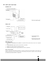
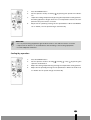
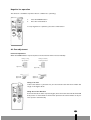
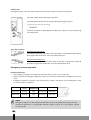
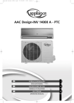
S1731 - S1735 6 BRUGSANVISNING 2 4 OPERATING MANUAL 20 1 GEBRUIKSAANWIJZING 38 : INSTRUKCJA OBSŁUGI 56 TR KULLANIM KILAVUZU 74 Dear Sir, Madam, Congratulations on the purchase of your airconditioner. You have acquired a high quality product that, if used responsibly, will give you many years of pleasure. Please read these instructions for use first in order to ensure the maximum life span of your airconditioner. On behalf of the manufacturer, we provide a 24-month guarantee on all material and production defects. Please enjoy your airconditioner. Yours sincerely, PVG International b.v. Customer service department 1. READ THE DIRECTIONS FOR USE FIRST. 2. IN CASE OF ANY DOUBT, CONTACT YOUR DEALER. 4 20 CONTENTS A Safety instructions 22 B Parts and functions 23 C Before operation 25 D Instructions for use 26 E Air filter 33 F Cleaning 33 G Trouble shooting 35 H Guarantee conditions 36 I Technical data 37 4 21 A SAFETY INSTRUCTIONS Install the device only when it complies with local regulations, by-laws and standards. The unit is only suitable for use in dry locations, indoors. Check the mains voltage and frequency. This unit is only suitable for earthed sockets, connection voltage 220 - 240 V. / 50 Hz. I M P O RTA N T The device MUST always have an earthed connection. If the power supply is not earthed, you may not connect the unit. The plug must always be easily accessible when the unit is connected. Read these instructions carefully and follow the instructions. Before connecting the unit, check the following: • The voltage supply must correspond with the mains voltage stated on the rating label. • The socket and power supply must be suitable for the current stated on the rating label. • The plug on the cable of the device must fit into the wall socket. • The device must be placed and mounted on a stable surface. The electricity supply to the device must be checked by a recognised professional if you have any doubts regarding the compatibility. • This device is manufactured according to CE safety standards. Nevertheless, you must take care, as with any other electrical device. • Do not cover the air inlet and outlet grill. • Never allow the device to come into contact with chemicals. • Never spray the unit with or submerge in water • Do not insert objects into the openings of the unit. • Never use an extension cable to connect the device to the electric power supply. If there is no suitable, earthed wall socket available, have one installed by a recognised electrician. • For safety reasons take care when children are in the surrounding of the device, as with any other electrical device. • Have any repairs only carried out by a recognised service engineer or your supplier. Follow the instructions for use and maintenance as indicated in the user manual of this device. • Always remove the plug of the unit from the wall socket when it is not in use. • A damaged power cord or plug must always be replaced by a recognised electrician or your supplier. 4 22 AT T E N T I O N ! • Never use the device with a damaged power cord, plug, cabinet or control panel. • Failing to follow the instructions may lead to nullification of the guarantee on this device. B PA RTS AND FUNCTIONS Outdoor unit Pipe and connecting cable Air inlet Drain hose Air outlet * Earthing terminal * Warm air comes out when cooling, cool air comes out when heating. Indoor unit Inlet grill Active carbon filter Screen filter Outlet ** Enzyme filter OUTDOOR UNIT Remote signal receiver *** Vertical louver Horizontal louver ** The air flow direction can be adjusted with the vertical and horizontal louvers. *** Beeping sound assures successfull signal transmission between wireless remote and the indoor unit. Operating panel 1. EMERGENCY OPERATION (manual) SWITCH. To operate the unit if the remote control is not operational. 2. POWER INDICATOR. Lights up when this function is activated. 3. TIMER. Time indicator lights up during preset time. 4. OPERATE. Operating indicator lights up when the unit is in operation. Auto recovery function lf there is any power failure during operation, operation status before power failure is memorized. 3~4 minutes after power recovery, the unit restarts automatically with previous operation status memorized (3~4 minutes is protective time for compressor). 4 23 AT T E N T I O N ! • Because of Auto Recovery Function, if shutting off the power supply during operation, the unit may restart irrespective your intention when turning on the power supply again. • If the unit is not to be used for a long time, shut off the power supply after terminating all operation with remote controller. Remote Control 1 TRANSMITTER Sends signals to the receiver of the indoor unit. 2 FAN SPEED INDICATION Indicates the fan speed selected by the fan speed button. When set at “AUTO”, the fan speed changes automatically according to the difference between the designated temperature and the room temperature. 3 OPERATION MODE INDICATION Indicates the current operating mode 4 TIME DISPLAY Indicates the present time or the timer. 5 TIMER MODE INDICATOR ON: The air conditioner starts operation at the designated time. OFF: The air conditioner stops operation at the designated time. 6 TEMPERATURE INDICATION Indicates the temperature set by the temperature setting buttons. 7 TRANSMITTING INDICATION Lights up when a signal is sent. 8 TEMPERATURE SETTING BUTTONS The setting temperature increases by 1°C (1.8°F) per press. The setting temperature decreases by 1°C (1.8°F) per press. Holding a button changes the temperature setting quickly. 9 LOUVER BUTTON Air flow direction can be changed horizontally (upward and downward) by each press. 4 24 NOTE • 00:00 A.M. – 12:00 A.M. = 00:00 – 12:00 • 00:00 P.M. – 12:00 P.M. = 12:00 – 24:00 j IONIZER BUTTON Generates negative ions. For the inverter models only, the power indicator lights up red. k FAN SPEED BUTTON Use to adjust the fan speed. The indication of the fa speed varies among “L” (Low), “M” (Medium), “H” (High), and “AUTO” each time the button is pressed. l OPERATION MODE BUTTON Use to change the operating mode. The indication of the operating mode varies among (Automatic), (Cooling), (Dry), (Circulating) and (Heating) each time the button is pressed.* m TIME ADJ BUTTON Press the “TIME ADJ” button to adjust the present time or the timer. n , BUTTONS Press these buttons to adjust the present time or the timer. Forward time Backward time Holding a button changes the time setting in 10-minute intervals. o TIMER FIXING BUTTONS Press these buttons to turn the timer ON or OFF. p SLEEP BUTTON Press this button for the Sleep setting. q ON/OFF BUTTON Starts operation with a press: stops operation with the next press. C BEFORE OPERAT I O N 1. Inserting batteries in remote control Placing the batteries Remove the battery cover in the direction of the arrow. Place the new batteries as indicated (ensure that the positive (+) and negative poles (-) are in the correct positions. Slide the battery cover back into place. NOTE Use 2 AAA (1.5 Volt) batteries. Do not use rechargeable batteries. Replace the batteries with new batteries of the same type (see above) when the display starts to fade. Storage of the remote control and tips for use The remote control can be placed in the wall-mounted holder. The wall-mounted holder is delivered together with the unit. Using the remote control Point the remote control at the receiver on the indoor unit of the air conditioner. The air conditioner can be operated in this manner up to a distance of approximately 7 meters. 2. Attaching filters This air conditioner is equipped with a 3 layer filter package to clean the circulated room air: • Screen filter: captures large dust particles. • Enzyme filter: neutralizes airborne micro organisms. • Active carbon filter: removes unpleasant odours from the air. COMMENT • Never use the airconditioner without the air filter. • Using the unit without the activated carbon filter and/or enzyme filter will not damage your airconditioner. In that case, airborne micro-organisms are not neutralised and unpleasant odours are not removed. • Only use suitable Zibro filters. This will prevent damage to your airconditioner. • Suitable filter packages are available at your dealer. 4 25 a. Open the front panel by pulling upward b. Remove the screen filters carefully. Push up the center tab of each screen filter slightly until it is released from the stopper, and remove the filters. Air filters Enzyme filter c. Attach active carbon and enzyme filter in the filterholder on each side of the air conditioner. Active carbon filter d. Attach the screen filters behind the stopper so that the “FRONT” indication is showing outward. Make sure that the filters are completely behind the stoppers. If the filters are not attached correctly, it may cause defects. Screen filters e. Close the front panel by pushing downward. C INSTRUCTIONS FOR USE Present time setting Example: Set to 3:50 p.m. 1. Press the “TIME ADJ” button once 2. Adjust the time with “+”, “-“ buttons. Holding a button changes time setting in 10-minute intervals. 3. Press the “TIME ADJ” button 3 times. The present time appears on the display. The setting is complete. NOTE Even if the actual time is not programmed, you can use all operations except “Timer operation” Circulation operation When you use other heating equipment, heated air accumulates in the upper space of the room. Using the operation “Circulation” will equalize the differences between the upper and lower spaces of the room and improves the efficiency of your heating equipment.. 4 26 1. Press the ON/OFF button 2. Set the operation mode, circulating , by pressing the operation mode but- ton. 3. Adjust the setting temperature by pressing the temperature setting buttons. Circulating Operation begins after the room temperature reaches the temperature set by the remote controller. 4. Adjust the fan speed by pressing the fan speed button. When the MODE is set at “AUTO”, the fan speed changes automatically. WA R N I N G ! • Do not place heating equipment right under the indoor unit and the remote controller. • Adjust air flow direction to avoid the direct airflow hitting to the heating equipment. • Provide adequate ventilation Cooling/dry operation 1. Press the ON/OFF button 2. Set the operation mode to Cooling , Heating or Dry , by pressing the operation mode button 3. Adjust the setting temperature by pressing the temperature setting buttons. 4. Adjust the fan speed by pressing the fan speed button. When the mode is set at “AUTO” the fan speed changes automatically. 4 27 NOTE! • If the unit operates in cooling or dry for a long time in high humidity (i.e., windows and doors are opened), dew and water drops may form on the indoor unit. Be aware that falling drops of water can damage your floor (e.g. carpet or parquet). • If you set a low temperature for dry operation, you may feel the air flow is cold. • During dry mode operation, the system performs the cooling operation until the room temperature reaches 1~2°C above the setting temperature. Then it continues dry mode operation intermittently with fan speed at “LO”, regardless of the designated speed. • During dry operation, the indoor unit stops operating for 3 minutes when the room temperature reaches the setting temperature. • During the heating operation, the outdoor unit may frost and heating capacity may be reduced. In this case, the unit stops its heating operation and conducts defrosting operation automatically. During the defrosting operation, the fans of the indoor and outdoor units stop. • Unless the heat exchanger gets warm enough, the air will not flow out to prevent cold air. Automatic operation In automatic operation the air conditioner selects the operation mode (cooling, dry, heating) according to the room temperature when it starts. • The air conditioner will restart in the previous mode if automatic operation is resumed within 3 hours from the switch-off. • Mode review. The computer checks and compares the room temperature regularly after the compressor shuts off, and will adapt the operating mode. 1. Press the ON/OFF button 2. Set the operation mode to Automatic “AUTO“, by pressing the operation mode button 3. Adjust the setting temperature by pressing the temperature setting buttons. 4. Adjust the fan speed by pressing the fan speed button. When the mode is set at “AUTO” the fan speed changes automatically. 4 28 NOTE If the selected mode by Automatic operation does not suit you, set the operation mode (cooling, dry, heating) with the operation mode button. Negative ion operation This function is available only when the air conditioner is operating. 1. Press the ON/OFF button 2. Press the ionizer button To stop negative ion operation, press the ionizer button. Air flow adjustment Horizontal adjustment When the ON/OFF button is pressed, the horizontal louver will move automatically. During cooling, dry operation During circulation, heating operation Level Approx. 10° Level Approx. 60° Level Approx. 10° Approx. 45° Level Approx. 10° Approx. 60° Swing of air flow If the louver button is pressed once, the horizontal louver will move within the range of the figure above. Fixing the air flow Direction If the louver button switch is pressed again, the horizontal louver will be fixed and that position is memorized. From the next operation the louver will be set at previous position automatically. 4 29 NOTE! • When the operation is off, the horizontal louver closes the outlet automatically. • Do not move the horizontal louver by hands. It may make the louver not to work correctly. In order to move the vertical louver, use wireless remote controller without fail. In case the louver does not work correctly, once stop the operation and turn on again. • During in cooling or dry operation, the horizontal louver should not be downward for long time. If this is done, dew drops may appear at the outlet (even the louver direction is in the swing range, the louver will move about 10 degrees from the horizontal after one hour). Vertical adjustment Adjust the vertical louver by moving the adjustment tabs manually. If the system is operated with the vertical louver faced completely to the left or right under high humidity, dew drops may appear at the outlet. Timer operation Before setting the timer, confirm that the present time is set accurately. Once you set the timer, the remote controller memorizes the setting. From the next time, you can operate the same timer mode just by pressing the ON/OFF button and the Timer fixing (“ON/OFF Timer”) button. You can use the combined function of the “ON Timer” and “OFF Timer”. “ON Timer” Example: set the “ON Timer” to 7 a.m. Operation starts at the set time. Programming the “ON Time” 1. Press the “TIME ADJ” 2 times. 2. Adjust the time with the button. The time setting changes in 10-minu- te intervals. Hold the button to fast forward the time. 3. Press the “TIME ADJ” button two times. The setting of “ON Time” is complete and the present time appears. 4. Press the timer fixing button “ON”. The “ON Time” is displayed for 2 seconds and then the present time appears. 4 30 Cancelling “ON Timer” Press the Timer fixing button “ON”. The timer lamp of the indoor unit goes off. “OFF Timer” Example: Set the “Off Timer” to 10 p.m. Operation starts at the set time. Programming the “OFF Time” 1. Press the “TIME ADJ” 3 times. 2. Adjust the time with the button. The time setting changes in 10-minu- te intervals. Hold the button to fast forward the time. 3. Press the “TIME ADJ” button once. The setting of “OFF Time” is complete and the present time appears. 4. Press the timer fixing button “ON”. The “ON Time” is displayed for 2 seconds and then the present time appears. Cancelling “OFF Timer” Press the timer fixing button “OFF”. The timer lamp of the indoor unit goes off. 4 31 “SLEEP Timer” Pressing this button starts the timer mode that will stop the operation after the setting time. Press the “SLEEP” button during the operation. The setting time repeats the following mode by pressing the button: Continuous operation (Sleep Operation: OFF). The operation stops after passing the setting time. Sleep Timer features During Cooling Operation The setting temperature rises 0.6°C after 30 minutes of Sleep Timer ON, and rises 0.6°C again after 30 minutes of the first temperature rise. During Heating Operation The setting temperature drops 0.6°C after 30 minutes of Sleep Timer ON, and drops 0.6°C again after 30 minutes of the first temperature drop. Emergency and test operation Emergency Operation • The emergency operation is needed only when the remote control can not be used. • When you press the Emergency Operation Switch, you will hear a beep and the emergency operation starts. • Emergency operation is preset for the following two modes, only based on the temperature of the room at the time of operation. Temperature Operation mode Designated temperature Timer mode Air flow Above 23°C Cooling 26°C Continuous Automatic Below 23°C Heating 23°C Continuous Automatic NOTE Emergency operation at the temperature between above 23°C and below 26°C just switch the machine in operation in “cooling mode” without actually “cooling”. It is not possible to operate in “Dry” mode. 4 32 Test operation • Same switch as used in Emergency operation. • Test operation is needed in special occasion when you need to test the “cooling operation” even with the room temperature below 16°C, therefore it is not for the normal operation at all. • Press the Emergency operation switch and hear the beep once, then keep on pressing the switch for more than 5 seconds but no more than 10 seconds. After the first 5 seconds you will hear two beeps then release the switch and you will have the Test Operation Mode. • The Test Operation Mode will run the air conditioner at “cooling” with air flow speed at “Hi” for 30 minutes and stops automatically. Termination of emergency or test operation • You can terminate the operation when you hear a beep by either pressing the switch once more, or by operating through remote control. • When you operate through remote control, is automatically get back to just normal operation mode by remote control. E AIR FILT E R This air conditioner is equipped with a 3 layer filter to clean the circulated room air. a. Screen filter; to remove bigger dust particles. b. Enzyme filter; neutralizes airborne micro organisms. c. Active carbon filter; to remove odours. NOTE The active carbon filter and the Enzyme filter are delivered in a plastic packaging. Remove plastic bags and install filters (refer chapter B). These filters take away unhealthy particles out of the room environment. The filter frame on the backside of the unit can be opened. The active carbon filter and enzyme filter can be installed or removed. The screen filter is part of the filter frame. a. The screen filter has to be cleaned regularly with a vacuum cleaner to avoid blocking of the air flow. b. The enzyme filter is recommended to be changed every 4-6 months. Unusual dirt, construction work, the presence of smoke, etc can shorten the lifetime of the enzyme filter. c. The active carbon filter can be cleaned with a vacuum cleaner when dusty but has to be changed at the same time as the Enzyme filter. NOTE • Remove the enzyme- and active carbon filter 2 -3 x per year and install new filters. The old filters can be disposed in the ‘Non-biological garbage container’. • Replacement filter packages are available at your dealer. • To run the unit without enzyme- and/or active carbon filter does not bring any harm to the air conditioner. In that case odours and airborne micro organisms are not removed from the circulated air. 4 33 F CLEANING Cleaning the front panel 1. Switch the machine off and remove the plug from the socket. 2. Hold the front panel at position “a” and pull it upwards. 3. Clean with a soft dry cloth. Use lukewarm water (max. 30° C) to remove stubborn dirt. 4. Never use volatile substances, such as benzine, gasoline, thinner or abrasives to remove dirt. 5. Never spray water on or in the indoor unit. Danger! 6. Replace the front panel and close it by pushing position “b” down. Cleaning the screen filter The screen filter must be cleaned regularly (approximately. every 2 weeks) Follow this procedure: 1. Switch the machine off completely. - Open the front panel (a). - Carefully pull the filter handle towards you. - Grip the handle and slide the filters out. 2. Cleaning the screen filter. Use a vacuum cleaner to remove dust. To remove stubborn dirt, clean the screen filter in lukewarm water. After cleaning, allow the screen filter to dry completely, out of direct sunlight. 3. Close the front panel. NOTE Never use the air conditioner without the screen filter. Maintenance of the negative ion generator (twice a year) 1. WA R N I N G ! Make sure that the air conditioner is not operating. 2. 4 34 Switch the machine off and remove the plug from the socket. Open the horizontal louver carefully by hand. G 3. Pick up dust on/around the negative ion generator. Gently rub the tip of the metal needle, in the negative ion generator, with a plastic (tooth-)brush. Do not use a cotton swab or other fluffy object. 4. Close carefully the horizontal louver. Plug in the power plug. The air conditioner can be used again. TROUBLE SHOOTING The following problems do not always indicate a fault. Please check them before contacting the service department: Problem Cause / Solution The plug is not inserted firmly in the socket. The unit does not operate. The batteries in the remote control are empty. The safety feature has been activated or the fuse has burnt out. Are the air inlets or outlets blocked? No cooled or heated air. Is the temperature set correctly? Is the screen filter dirty? No effective operation. Faults (due to static electricity discharges or disruptions in the power supply) will prevent the machine from operating correctly. If this is the case, pull the plug out of the socket, and then reinsert it after 2-3 seconds. Does not start immediately. Changing the mode during operation: 3 minute delay. Unusual odour. Odour may be caused by another source – furniture, cigarettes, etc. The unit expels air that it has sucked in. The sound of running water. Caused by the refrigerant in the air conditioner: this does not indicate a fault. The sound of defrosting in the heating mode. A creaking sound. The sound may be caused by the expansion/shrinkage of the front panel as a consequence of temperature fluctuations. Condensation/mist is created when the air temperature in the Mist/moisture is expelled from the air outlet. room drops significantly due to the fact that cold air is expelled in the COOLING or DRY mode. The red compressor indicator flashes constantly and the fan in the indoor unit ceases to operate. The unit will switch from the heating mode to the defrosting mode. The indicator light will go out within 10 minutes and the unit will return to the heating mode. Distance too great. Make sure the remote control is correctly aimed at the control panel. Remote control does not function. Remote control signal not detected by control panel. Make sure the remote control is correctly aimed at the control panel. Batteries empty. Replace the batteries. Never try to repair or dismantle the air conditioner yourself. Incompetent repairs result in loss of warr a n t y and can endanger the user. 4 35 H GUARANTEE CONDITIONS The air conditioner is supplied with a 24-month guarantee, commencing on the date of purchase. All material and manufacturing defects will be repaired or replaced free of charge within this period. The following rules apply: 1. We expressly refuse all further damage claims, including claims for collateral damage. 2. Repairs to or replacement of components within the guarantee period will not result in an extension of the guarantee. 3. The guarantee is invalidated if any modifications have been made, non genuine parts are fitted or repairs are carried out by third parties. 4. Components subject to normal wear, such as the filter, are not covered by the guarantee. 5. The guarantee is valid only when you present the original, dated purchase invoice and if no modifications have been made. 6. The guarantee is invalid for damage caused by neglect or by actions that deviate from those in this instruction booklet. 7. Transportation costs and the risks involved during the transportation of the air conditioner or air conditioner components shall always be for the account of the purchaser. 8. Damage caused by not using suitable Zibro filters is not covered by the guarantee. 9. Refrigerant loss and/or leakage because of incompetent (dis)connecting the units is not covered by the guarantee conditions applicable to this product. To prevent unnecessary expense, we recommend that you always first carefully consult the instructions for use. Take the air conditioner to your dealer for repairs if these instructions do not provide a solution. 4 36 I TECHNICAL DATA Model Type air-conditioner Cooling capacity (max) * kW EE Class* EER* Heating capacity (max) * kW Heating performance COP* Dehumidifying capacity ** DC inverter wall mounted 3.1 3.5 A A 3.47 3.41 3.6 4.2 A A 4.16 38 48 kW 0.76 0.97 kW 0.86 0.88 V / Hz / Ph 220 - 240 / 50 / 1 220 - 240 / 50 / 1 A 3.6 / 4.1 4.6 / 4.2 quantity / cc 9000 9000 m3/h 468 / 516 558 / 588 80 100 Rotary Rotary Current (nom.) cooling / heating Air flow (nom.)** cooling / heating DC inverter wall mounted 3.74 Power consumption heating Generated negative ions **** S1735 L / 24h Power consumption cooling Power supply S1731 For rooms up to** 3 m Compressor type Fan speeds Thermostatic range ºC Controls manual / mechanic / electronic Remote control Yes / No Air filter type(s) 3 3 16 - 30 16 - 30 Electronic remote Electronic remote Y Y Screen, Enzyme, Active carbon Screen, Enzyme, Active carbon Refrigerant type / charge r / gr R410A / 850 gr R410A / 850 gr Refrigerant pipe diameter Liquid - Gas Inch 1/4 - 3/8 1/4 - 3/8 Pressure suction / discharge bar 11.5 / 41.5 11.5 / 41.5 Dimensions indoor unit (w x d x h) mm 795 x 192 x 265 795 x 199 x 265 Dimensions outdoor unit (w x d x h) mm 780 x 277 x 530 780 x 277 x 530 Net weight indoor unit kg 7.0 8.1 Net weight outdoor unit kg 30.0 30.0 Gross weight indoor unit kg 11 12 Gross weight outdoor unit kg 34 35 Noise level indoor unit dB 25 - 38 25 - 43 Noise level outdoor unit dB 44 44 Unit protection indoor IP IP X0 IP X0 Unit protection outdoor IP IP X4 IP X4 * EN 14511 ** To be used as indication *** Moisture removal at 32°C, 80% RH **** Measured at air discharge Waste electrical products should not be disposed with household waste. Please recycle where facilities exist. Check with your local authority or retailer for recycling advice. 4 37 DISTRIBUTED IN EUROPE BY PVG INTERNATIONAL B.V. i ÖSTERREICH PVG Austria VertriebsgmbH Salaberg 49 3350 HAAG tel: +43 7434 44867 fax: +43 7434 44868 email: [email protected] e BELGIË PVG Belgium NV/SA Industrielaan 55 2900 SCHOTEN tel: +32 3 326 39 39 fax: +32 3 326 26 39 email: [email protected] q SCHWEIZ PVG Schweiz AG Genuastrasse 15 4142 MÜNCHENSTEIN tel: +41 61 337 26 51 fax: +41 61 337 26 78 email: [email protected] 2 DEUTSCHLAND PVG Deutschland GmbH Beiersdorfstraße 4 46446 EMMERICH tel: +49 2821 76713 fax: +31 412 622 893 email: [email protected] 6 DANMARK PVG Scandinavia A/S Niels Bohrsvej 10 6100 HADERSLEV tel: +45 73 53 02 02 fax: +45 73 53 02 04 email: [email protected] 5 ESPAÑA PVG España S.A. Pol. Ind. San José de Valderas II Comunidad ”La Alameda” C/ Aurora Boreal, 19 28918 LEGANÉS (Madrid) tel: +34 91 611 31 13 fax: +34 91 612 73 04 email: [email protected] 3 FRANCE PVG France SARL 4, Rue Jean Sibélius B.P. 185 76410 SOTTEVILLE SOUS LE VAL tel: +33 2 32 96 07 47 fax: +33 0 820 34 64 84 email: [email protected] 4 UNITED KINGDOM Lister Gases Bridge Street Holloway Bank, Wednesbury West Midlands WS10 OAW tel.: +44 121 506 1818 fax: +44 121 505 1744 email: [email protected] > ITALIA PVG Italy SRL Via Niccolò Copernico 5 50051 CASTELFIORENTINO (FI) tel: +39 571 628 500 fax: +39 571 628 504 email: [email protected] u NORGE Sunwind - Gylling A/S Rudsletta 71-75 / P.O. Box 64 N-1309 RUD tel: +47 67 17 13 70 fax: +47 67 17 13 80 email: [email protected] 1 NEDERLAND PVG International B.V. P.O. Box 96 5340 AB OSS tel: +31 412 694 694 fax: +31 412 622 893 email: [email protected] 9 PORTUGAL Gardena, Lda Recta da Granja do Marquês ALGUEIRÃO 2725-596 MEM MARTINS tel: + 35 21 92 28 530 fax: + 35 21 92 28 536 email: [email protected] : POLSKA PVG Polska Sp. z. o. o. ul. Ko∂cielnej 110 26-800 Bia≥obrzegi tel: +48 48 613 00 70 fax: +48 48 613 00 70 email: [email protected] TR TURKEY PVG Is›tma Klima So¤utma Ltd.Sti. Ataturk Cad. No 380 Ak Ishani Kat 6 35220 Alsancak IZMIR - TURKEY tel: + 90 232 463 33 72 fax: + 90 232 463 69 91 email: [email protected]