1
Cat. No. W430-E1-02
SYSMAC CS Series
CS1D-ETN21D (100Base-TX)
Ethernet Units for CS1D PLCs
OPERATION MANUAL
CS1D-ETN21D (100Base-TX)
Ethernet Units for CS1D PLCs
Operation Manual
Revised June 2008
iv
Notice:
OMRON products are manufactured for use according to proper procedures by a qualified operator
and only for the purposes described in this manual.
The following conventions are used to indicate and classify precautions in this manual. Always heed
the information provided with them. Failure to heed precautions can result in injury to people or damage to property.
!DANGER
Indicates an imminently hazardous situation which, if not avoided, will result in death or
serious injury.
!WARNING
Indicates a potentially hazardous situation which, if not avoided, could result in death or
serious injury.
!Caution
Indicates a potentially hazardous situation which, if not avoided, may result in minor or
moderate injury, or property damage.
OMRON Product References
All OMRON products are capitalized in this manual. The word “Unit” is also capitalized when it refers to
an OMRON product, regardless of whether or not it appears in the proper name of the product.
The abbreviation “Ch,” which appears in some displays and on some OMRON products, often means
“word” and is abbreviated “Wd” in documentation in this sense.
The abbreviation “PLC” means Programmable Controller. “PC” is used, however, in some Programming Device displays to mean Programmable Controller.
Visual Aids
The following headings appear in the left column of the manual to help you locate different types of
information.
Note Indicates information of particular interest for efficient and convenient operation of the product.
1,2,3...
1. Indicates lists of one sort or another, such as procedures, checklists, etc.
OMRON, 2004
All rights reserved. No part of this publication may be reproduced, stored in a retrieval system, or transmitted, in any form, or
by any means, mechanical, electronic, photocopying, recording, or otherwise, without the prior written permission of
OMRON.
No patent liability is assumed with respect to the use of the information contained herein. Moreover, because OMRON is constantly striving to improve its high-quality products, the information contained in this manual is subject to change without
notice. Every precaution has been taken in the preparation of this manual. Nevertheless, OMRON assumes no responsibility
for errors or omissions. Neither is any liability assumed for damages resulting from the use of the information contained in
this publication.
v
vi
TABLE OF CONTENTS
PRECAUTIONS . . . . . . . . . . . . . . . . . . . . . . . . . . . . . . . . . . . . . xvii
1
Intended Audience . . . . . . . . . . . . . . . . . . . . . . . . . . . . . . . . . . . . . . . . . . . . . . . . . . . . . . . . . . .
xviii
2
General Precautions . . . . . . . . . . . . . . . . . . . . . . . . . . . . . . . . . . . . . . . . . . . . . . . . . . . . . . . . . .
xviii
3
Safety Precautions. . . . . . . . . . . . . . . . . . . . . . . . . . . . . . . . . . . . . . . . . . . . . . . . . . . . . . . . . . . .
xviii
4
Operating Environment Precautions . . . . . . . . . . . . . . . . . . . . . . . . . . . . . . . . . . . . . . . . . . . . . .
xix
5
Application Precautions . . . . . . . . . . . . . . . . . . . . . . . . . . . . . . . . . . . . . . . . . . . . . . . . . . . . . . .
xix
6
Conformance to EC Directives . . . . . . . . . . . . . . . . . . . . . . . . . . . . . . . . . . . . . . . . . . . . . . . . . .
xxi
SECTION 1
Features and System Configuration . . . . . . . . . . . . . . . . . . . . .
1
1-1
Ethernet Unit Function Guide . . . . . . . . . . . . . . . . . . . . . . . . . . . . . . . . . . . . . . . . . . . . . . . . . . .
2
1-2
Features . . . . . . . . . . . . . . . . . . . . . . . . . . . . . . . . . . . . . . . . . . . . . . . . . . . . . . . . . . . . . . . . . . . .
5
1-3
System Configuration . . . . . . . . . . . . . . . . . . . . . . . . . . . . . . . . . . . . . . . . . . . . . . . . . . . . . . . . .
7
1-4
Specifications . . . . . . . . . . . . . . . . . . . . . . . . . . . . . . . . . . . . . . . . . . . . . . . . . . . . . . . . . . . . . . .
11
1-5
Overview of Communications Functions . . . . . . . . . . . . . . . . . . . . . . . . . . . . . . . . . . . . . . . . . .
13
1-6
Nomenclature and Functions . . . . . . . . . . . . . . . . . . . . . . . . . . . . . . . . . . . . . . . . . . . . . . . . . . .
17
1-7
Comparison with CS1W-ETN21. . . . . . . . . . . . . . . . . . . . . . . . . . . . . . . . . . . . . . . . . . . . . . . . .
19
SECTION 2
Installation and Initial Setup. . . . . . . . . . . . . . . . . . . . . . . . . . .
21
2-1
Overview of Startup Procedure . . . . . . . . . . . . . . . . . . . . . . . . . . . . . . . . . . . . . . . . . . . . . . . . . .
22
2-2
Main Points in Creating a Duplex Ethernet Network . . . . . . . . . . . . . . . . . . . . . . . . . . . . . . . . .
25
2-3
Switch Settings . . . . . . . . . . . . . . . . . . . . . . . . . . . . . . . . . . . . . . . . . . . . . . . . . . . . . . . . . . . . . .
26
2-4
Mounting to a PLC . . . . . . . . . . . . . . . . . . . . . . . . . . . . . . . . . . . . . . . . . . . . . . . . . . . . . . . . . . .
29
2-5
Network Installation . . . . . . . . . . . . . . . . . . . . . . . . . . . . . . . . . . . . . . . . . . . . . . . . . . . . . . . . . .
30
2-6
Connecting to the Network . . . . . . . . . . . . . . . . . . . . . . . . . . . . . . . . . . . . . . . . . . . . . . . . . . . . .
34
2-7
Creating I/O Tables . . . . . . . . . . . . . . . . . . . . . . . . . . . . . . . . . . . . . . . . . . . . . . . . . . . . . . . . . . .
36
2-8
Enabling Duplex Communications . . . . . . . . . . . . . . . . . . . . . . . . . . . . . . . . . . . . . . . . . . . . . . .
37
2-9
Unit Setup Procedure . . . . . . . . . . . . . . . . . . . . . . . . . . . . . . . . . . . . . . . . . . . . . . . . . . . . . . . . .
39
2-10 Basic Settings . . . . . . . . . . . . . . . . . . . . . . . . . . . . . . . . . . . . . . . . . . . . . . . . . . . . . . . . . . . . . . .
41
2-11 Communications Test . . . . . . . . . . . . . . . . . . . . . . . . . . . . . . . . . . . . . . . . . . . . . . . . . . . . . . . . .
45
2-12 Replacing an Ethernet Unit . . . . . . . . . . . . . . . . . . . . . . . . . . . . . . . . . . . . . . . . . . . . . . . . . . . . .
47
SECTION 3
CX-Programmer Unit Setup . . . . . . . . . . . . . . . . . . . . . . . . . . .
51
3-1
Setup . . . . . . . . . . . . . . . . . . . . . . . . . . . . . . . . . . . . . . . . . . . . . . . . . . . . . . . . . . . . . . . . . . . . . .
52
3-2
FINS/TCP . . . . . . . . . . . . . . . . . . . . . . . . . . . . . . . . . . . . . . . . . . . . . . . . . . . . . . . . . . . . . . . . . .
53
SECTION 4
Ethernet Unit Memory Allocations. . . . . . . . . . . . . . . . . . . . . .
57
4-1
CIO Area Allocations . . . . . . . . . . . . . . . . . . . . . . . . . . . . . . . . . . . . . . . . . . . . . . . . . . . . . . . . .
58
4-2
DM Area Allocations . . . . . . . . . . . . . . . . . . . . . . . . . . . . . . . . . . . . . . . . . . . . . . . . . . . . . . . . .
65
4-3
Auxiliary Area Data . . . . . . . . . . . . . . . . . . . . . . . . . . . . . . . . . . . . . . . . . . . . . . . . . . . . . . . . . .
66
vii
TABLE OF CONTENTS
SECTION 5
Determining IP Addresses . . . . . . . . . . . . . . . . . . . . . . . . . . . . .
71
5-1
IP Addresses . . . . . . . . . . . . . . . . . . . . . . . . . . . . . . . . . . . . . . . . . . . . . . . . . . . . . . . . . . . . . . . .
72
5-2
IP Addresses in FINS Communications . . . . . . . . . . . . . . . . . . . . . . . . . . . . . . . . . . . . . . . . . . .
74
5-3
Private and Global Addresses . . . . . . . . . . . . . . . . . . . . . . . . . . . . . . . . . . . . . . . . . . . . . . . . . . .
84
SECTION 6
FINS Communications. . . . . . . . . . . . . . . . . . . . . . . . . . . . . . . .
89
6-1
Overview of FINS Communications. . . . . . . . . . . . . . . . . . . . . . . . . . . . . . . . . . . . . . . . . . . . . .
90
6-2
FINS/UDP Method . . . . . . . . . . . . . . . . . . . . . . . . . . . . . . . . . . . . . . . . . . . . . . . . . . . . . . . . . . .
92
6-3
FINS/TCP Method . . . . . . . . . . . . . . . . . . . . . . . . . . . . . . . . . . . . . . . . . . . . . . . . . . . . . . . . . . .
94
6-4
Creating Routing Tables . . . . . . . . . . . . . . . . . . . . . . . . . . . . . . . . . . . . . . . . . . . . . . . . . . . . . . .
98
6-5
Using FINS Applications . . . . . . . . . . . . . . . . . . . . . . . . . . . . . . . . . . . . . . . . . . . . . . . . . . . . . .
102
6-6
Communicating between OMRON PLCs . . . . . . . . . . . . . . . . . . . . . . . . . . . . . . . . . . . . . . . . . .
113
6-7
Network Status Performance . . . . . . . . . . . . . . . . . . . . . . . . . . . . . . . . . . . . . . . . . . . .
129
6-8
Precautions on High Traffic in FINS Communications . . . . . . . . . . . . . . . . . . . . . . . . . . . . . . .
130
SECTION 7
FINS Commands Addressed to Ethernet Units . . . . . . . . . . . . 133
7-1
Command Codes and Response Codes . . . . . . . . . . . . . . . . . . . . . . . . . . . . . . . . . . . . . . . . . . . .
134
7-2
Command/Response Reference . . . . . . . . . . . . . . . . . . . . . . . . . . . . . . . . . . . . . . . . . . . . . . . . .
135
SECTION 8
Troubleshooting . . . . . . . . . . . . . . . . . . . . . . . . . . . . . . . . . . . . . 161
8-1
Troubleshooting with Indicators . . . . . . . . . . . . . . . . . . . . . . . . . . . . . . . . . . . . . . . . . . . . . . . . .
162
8-2
Error Status . . . . . . . . . . . . . . . . . . . . . . . . . . . . . . . . . . . . . . . . . . . . . . . . . . . . . . . . . . . . . . . . .
163
8-3
Error Log. . . . . . . . . . . . . . . . . . . . . . . . . . . . . . . . . . . . . . . . . . . . . . . . . . . . . . . . . . . . . . . . . . .
164
8-4
Troubleshooting Procedures . . . . . . . . . . . . . . . . . . . . . . . . . . . . . . . . . . . . . . . . . . . . . . . . . . . .
171
8-5
Troubleshooting with Response Codes . . . . . . . . . . . . . . . . . . . . . . . . . . . . . . . . . . . . . . . . . . . .
174
Appendices
A
Ethernet Network Parameters . . . . . . . . . . . . . . . . . . . . . . . . . . . . . . . . . . . . . . . . . . . . . . . . . .
177
B
Buffer Configuration . . . . . . . . . . . . . . . . . . . . . . . . . . . . . . . . . . . . . . . . . . . . . . . . . . . . . . . . .
179
C
TCP Status Transitions . . . . . . . . . . . . . . . . . . . . . . . . . . . . . . . . . . . . . . . . . . . . . . . . . . . . . . . .
181
D
ASCII Characters . . . . . . . . . . . . . . . . . . . . . . . . . . . . . . . . . . . . . . . . . . . . . . . . . . . . . . . . . . . .
183
E
Maintenance . . . . . . . . . . . . . . . . . . . . . . . . . . . . . . . . . . . . . . . . . . . . . . . . . . . . . . . . . . . . . . . .
185
F
Inspections . . . . . . . . . . . . . . . . . . . . . . . . . . . . . . . . . . . . . . . . . . . . . . . . . . . . . . . . . . . . . . . . .
187
G
Using a Memory Card Text File to Set Up an Ethernet Unit . . . . . . . . . . . . . . . . . . . . . . . . . . .
189
Index . . . . . . . . . . . . . . . . . . . . . . . . . . . . . . . . . . . . . . . . . . . . . . 199
Revision History . . . . . . . . . . . . . . . . . . . . . . . . . . . . . . . . . . . . . 205
viii
About this Manual:
This manual describes the installation and operation of the CS1D-ETN21D Ethernet Unit for CS1D
PLCs (100Base-TX) and includes the sections described below.
Please read this manual carefully and be sure you understand the information provided before
attempting to install or operate the CS1D Ethernet Unit. Be sure to read the precautions provided in
the following section.
Precautions provides general precautions for using the CS1D-ETN21D CS1D Ethernet Units
(100Base-TX).
Section 1 introduces the features, describes the system configuration and Unit parts, and provides
Unit specifications.
Section 2 explains how to install the Ethernet Unit and make the initial settings required for operation.
Section 3 provides information for setting communications using CX-Programmer.
Section 4 describes the words allocated in the CIO Area and the DM Area for Ethernet Units.
Section 5 explains how to manage and use IP addresses.
Section 6 provides information on communicating on Ethernet Systems and interconnected networks
using FINS commands.
Section 7 describes the FINS commands that can be sent to an Ethernet Unit and the responses that
are returned by the Ethernet Unit.
Section 8 describes information and procedures that can be used to troubleshoot problems that sometimes occur with Ethernet Unit and Ethernet communications.
Appendices provide information on Ethernet network parameters, the buffer configuration, TCP status
transitions, ASCII characters, maintenance, and inspections.
ix
Relevant Manuals
The following table lists CS-series manuals that contain information relevant to CS1D Ethernet Units.
Manual
number
Model
W430
CS1D-ETN21D
W420
CS1W-ETN21
CJ1W-ETN21
W421
CS1W-ETN21
CJ1W-ETN21
W343
CS1W-ETN01
CS1W-ETN11
CJ1W-ETN11
CS1G/H-CPU@@H
CS1G/H-CPU-@@V1
CS1W-SCU21
CS1W-SCB21/41
CJ1G/H-CPU@@H
CJ1G-CPU@@
CJ1W-SCU41
CS1D-CPU@@H
CS1D-CPU@@S
CS1D-DPL1
CS1D-PA207R
W342
W405
Name
Ethernet Units Oper- Provides information on operating and installing
ation Manual
100Base-TX Ethernet Units, including details on basic
(this manual)
settings and FINS communications.
Refer to the Communications Commands Reference
Manual (W342) for details on FINS commands that can
be sent to CS-series CPU Units when using the FINS
communications service.
Ethernet Units Oper- Provides information on operating and installing
ation Manual
100Base-TX Ethernet Units, including details on basic
Construction of Net- settings and FINS communications.
works
Refer to the Communications Commands Reference
Manual (W342) for details on FINS commands that can
(this manual)
be sent to CS-series and CJ-series CPU Units when
using the FINS communications service.
Ethernet Units Operation Manual
Construction of
Applications
Ethernet Units Operation Manual
Provides information on constructing host applications for
100Base-TX Ethernet Units, including functions for sending/receiving mail, socket service, automatic clock adjustment, FTP server functions, and FINS communications.
Describes the installation and operation of the 10Base-5
and 10Base-T Ethernet Units.
Communications
Commands Reference Manual
Describes the C-series (Host Link) and FINS communications commands used when sending communications
commands to CS-series and CJ-series CPU Units.
Duplex System
Operation Manual
Provides an outline of and describes the design, installation, maintenance, and other basic operations for a
Duplex System based on CS1D CPU Units.
Provides an outline of, and describes the design, installation, maintenance, and other basic operations for the CSseries PLCs. Information is also included on features,
system configuration, wiring, I/O memory allocations, and
troubleshooting.
Use together with the Programmable Controllers Programming Manual (W394).
Describes programming, tasks, file memory, and other
functions for the CS-series and CJ-series PLCs.
Use together with the Programmable Controllers Operation Manual (W339 for CS-series PLCs and W393 for CJseries PLCs).
W339
CS1G/H-CPU@@H
CS1G/H-CPU-@@V1
Programmable Controllers Operation
Manual
W394
CS1G/H-CPU@@H
CS1G/H-CPU-@@V1
CJ1G/H-CPU@@H
CJ1G-CPU@@
Programmable Controllers Programming Manual
W340
CS1G/H-CPU@@H
CS1G/H-CPU-@@V1
CJ1G/H-CPU@@H
CJ1G-CPU@@
Programmable Controllers Instructions
Reference Manual
x
Contents
Describes the ladder diagram programming instructions
supported by CS-series and CJ-series PCs. Use together
with the Programmable Controllers Operation Manual
(W339 for CS-series PLCs and W393 for CJ-series
PLCs), and Programmable Controllers Programming
Manual (W394).
Manual
number
W414
Model
Name
WS02-CX-@@EV3
CX-Programmer
Ver.3.@ Operation
Manual
W341
CQM1H-PRO01
CQM1-PRO01
C200H-PRO27 +
CS1W-KS001
Programming Consoles Operation
Manual
W336
CS1W-SCB21/41
CS1W-SCU21
CJ1W-SCU41
Contents
Provides information on how to use the CX-Programmer,
a Windows-based programming device, and CX-Net, a
Windows-based network configuration tool.
Use together with the Programmable Controllers Operation Manual (W339 for CS-series PLCs and W393 for CJseries PLCs), Programmable Controllers Programming
Manual (W394) and the Programmable Controllers
Instructions Reference Manual (W340) to perform programming.
Provides information on how to operate the Programming
Console.
Use together with the Programmable Controllers Operation Manual (W339 for CS-series PLCs and W393 for CJseries PLCs), Programmable Controllers Programming
Manual (W394) and the Programmable Controllers
Instructions Reference Manual (W340) to perform programming.
Serial CommunicaAccessing the PLC connected to the CX-Programmer via
tions Boards and
Ethernet or the host computer or other device connected
Serial Communicato the Serial Communications Board or Unit.
tions Units Operation Describes the use of Serial Communications Units and
Manual
Boards, including details on hardware, software, and
standard system protocols.
!WARNING Failure to read and understand the information provided in this manual may result in personal injury or death, damage to the product, or product failure. Please read each section
in its entirety and be sure you understand the information provided in the section and
related sections before attempting any of the procedures or operations given.
xi
xii
Read and Understand this Manual
Please read and understand this manual before using the product. Please consult your OMRON
representative if you have any questions or comments.
Warranty and Limitations of Liability
WARRANTY
OMRON's exclusive warranty is that the products are free from defects in materials and workmanship for a
period of one year (or other period if specified) from date of sale by OMRON.
OMRON MAKES NO WARRANTY OR REPRESENTATION, EXPRESS OR IMPLIED, REGARDING NONINFRINGEMENT, MERCHANTABILITY, OR FITNESS FOR PARTICULAR PURPOSE OF THE
PRODUCTS. ANY BUYER OR USER ACKNOWLEDGES THAT THE BUYER OR USER ALONE HAS
DETERMINED THAT THE PRODUCTS WILL SUITABLY MEET THE REQUIREMENTS OF THEIR
INTENDED USE. OMRON DISCLAIMS ALL OTHER WARRANTIES, EXPRESS OR IMPLIED.
LIMITATIONS OF LIABILITY
OMRON SHALL NOT BE RESPONSIBLE FOR SPECIAL, INDIRECT, OR CONSEQUENTIAL DAMAGES,
LOSS OF PROFITS OR COMMERCIAL LOSS IN ANY WAY CONNECTED WITH THE PRODUCTS,
WHETHER SUCH CLAIM IS BASED ON CONTRACT, WARRANTY, NEGLIGENCE, OR STRICT
LIABILITY.
In no event shall the responsibility of OMRON for any act exceed the individual price of the product on which
liability is asserted.
IN NO EVENT SHALL OMRON BE RESPONSIBLE FOR WARRANTY, REPAIR, OR OTHER CLAIMS
REGARDING THE PRODUCTS UNLESS OMRON'S ANALYSIS CONFIRMS THAT THE PRODUCTS
WERE PROPERLY HANDLED, STORED, INSTALLED, AND MAINTAINED AND NOT SUBJECT TO
CONTAMINATION, ABUSE, MISUSE, OR INAPPROPRIATE MODIFICATION OR REPAIR.
xiii
Application Considerations
SUITABILITY FOR USE
OMRON shall not be responsible for conformity with any standards, codes, or regulations that apply to the
combination of products in the customer's application or use of the products.
At the customer's request, OMRON will provide applicable third party certification documents identifying
ratings and limitations of use that apply to the products. This information by itself is not sufficient for a
complete determination of the suitability of the products in combination with the end product, machine,
system, or other application or use.
The following are some examples of applications for which particular attention must be given. This is not
intended to be an exhaustive list of all possible uses of the products, nor is it intended to imply that the uses
listed may be suitable for the products:
• Outdoor use, uses involving potential chemical contamination or electrical interference, or conditions or
uses not described in this manual.
• Nuclear energy control systems, combustion systems, railroad systems, aviation systems, medical
equipment, amusement machines, vehicles, safety equipment, and installations subject to separate
industry or government regulations.
• Systems, machines, and equipment that could present a risk to life or property.
Please know and observe all prohibitions of use applicable to the products.
NEVER USE THE PRODUCTS FOR AN APPLICATION INVOLVING SERIOUS RISK TO LIFE OR
PROPERTY WITHOUT ENSURING THAT THE SYSTEM AS A WHOLE HAS BEEN DESIGNED TO
ADDRESS THE RISKS, AND THAT THE OMRON PRODUCTS ARE PROPERLY RATED AND
INSTALLED FOR THE INTENDED USE WITHIN THE OVERALL EQUIPMENT OR SYSTEM.
PROGRAMMABLE PRODUCTS
OMRON shall not be responsible for the user's programming of a programmable product, or any
consequence thereof.
xiv
Disclaimers
CHANGE IN SPECIFICATIONS
Product specifications and accessories may be changed at any time based on improvements and other
reasons.
It is our practice to change model numbers when published ratings or features are changed, or when
significant construction changes are made. However, some specifications of the products may be changed
without any notice. When in doubt, special model numbers may be assigned to fix or establish key
specifications for your application on your request. Please consult with your OMRON representative at any
time to confirm actual specifications of purchased products.
DIMENSIONS AND WEIGHTS
Dimensions and weights are nominal and are not to be used for manufacturing purposes, even when
tolerances are shown.
PERFORMANCE DATA
Performance data given in this manual is provided as a guide for the user in determining suitability and does
not constitute a warranty. It may represent the result of OMRON's test conditions, and the users must
correlate it to actual application requirements. Actual performance is subject to the OMRON Warranty and
Limitations of Liability.
ERRORS AND OMISSIONS
The information in this manual has been carefully checked and is believed to be accurate; however, no
responsibility is assumed for clerical, typographical, or proofreading errors, or omissions.
xv
xvi
PRECAUTIONS
This section provides general precautions for using the CS1D-ETN21D CS1D Ethernet Units (100Base-TX).
The information contained in this section is important for the safe and reliable application of Ethernet Units. You
must read this section and understand the information contained before attempting to set up or operate an Ethernet
Unit.
1
2
3
4
5
6
Intended Audience . . . . . . . . . . . . . . . . . . . . . . . . . . . . . . . . . . . . . . . . . . . . .
General Precautions . . . . . . . . . . . . . . . . . . . . . . . . . . . . . . . . . . . . . . . . . . . .
Safety Precautions. . . . . . . . . . . . . . . . . . . . . . . . . . . . . . . . . . . . . . . . . . . . . .
Operating Environment Precautions . . . . . . . . . . . . . . . . . . . . . . . . . . . . . . . .
Application Precautions . . . . . . . . . . . . . . . . . . . . . . . . . . . . . . . . . . . . . . . . .
Conformance to EC Directives . . . . . . . . . . . . . . . . . . . . . . . . . . . . . . . . . . . .
6-1
Applicable Directives . . . . . . . . . . . . . . . . . . . . . . . . . . . . . . . . . . . .
6-2
Concepts . . . . . . . . . . . . . . . . . . . . . . . . . . . . . . . . . . . . . . . . . . . . . .
xviii
xviii
xviii
xix
xix
xxi
xxi
xxi
xvii
1
Intended Audience
1
Intended Audience
This manual is intended for the following personnel, who must also have
knowledge of electrical systems (an electrical engineer or the equivalent).
• Personnel in charge of installing FA systems.
• Personnel in charge of designing FA systems.
• Personnel in charge of managing FA systems and facilities.
2
General Precautions
The user must operate the product according to the performance specifications described in the operation manuals.
Before using the product under conditions which are not described in the
manual or applying the product to nuclear control systems, railroad systems,
aviation systems, vehicles, combustion systems, medical equipment, amusement machines, safety equipment, and other systems, machines, and equipment that may have a serious influence on lives and property if used
improperly, consult your OMRON representative.
Make sure that the ratings and performance characteristics of the product are
sufficient for the systems, machines, and equipment, and be sure to provide
the systems, machines, and equipment with double safety mechanisms.
This manual provides information for programming and operating the Unit. Be
sure to read this manual before attempting to use the Unit and keep this manual close at hand for reference during operation.
!WARNING It is extremely important that a PLC and all PLC Units be used for the specified purpose and under the specified conditions, especially in applications that
can directly or indirectly affect human life. You must consult with your OMRON
representative before applying a PLC System to the above-mentioned applications.
3
Safety Precautions
!WARNING Do not attempt to take any Unit apart while the power is being supplied. Doing
so may result in electric shock.
!WARNING Do not touch any of the terminals or terminal blocks while the power is being
supplied. Doing so may result in electric shock.
!WARNING Do not attempt to disassemble, repair, or modify any Units. Any attempt to do
so may result in malfunction, fire, or electric shock.
!Caution Execute online editing only after confirming that no adverse effects will be
caused by extending the cycle time. Otherwise, the input signals may not be
readable.
xviii
Operating Environment Precautions
4
• Emergency stop circuits, interlock circuits, limit circuits, and similar safety
measures must be provided in external control circuits.
!Caution Tighten the screws on the terminal block of the AC Power Supply Unit to the
torque specified in the operation manual. The loose screws may result in
burning or malfunction.
4
Operating Environment Precautions
!Caution Do not operate the control system in the following locations:
• Locations subject to direct sunlight.
• Locations subject to temperatures or humidity outside the range specified
in the specifications.
• Locations subject to condensation as the result of severe changes in temperature.
• Locations subject to corrosive or flammable gases.
• Locations subject to dust (especially iron dust) or salts.
• Locations subject to exposure to water, oil, or chemicals.
• Locations subject to shock or vibration.
!Caution Take appropriate and sufficient countermeasures when installing systems in
the following locations:
• Locations subject to static electricity or other forms of noise.
• Locations subject to strong electromagnetic fields.
• Locations subject to possible exposure to radioactivity.
• Locations close to power supplies.
5
Application Precautions
Observe the following precautions when using the Ethernet Unit.
!WARNING Always heed these precautions. Failure to abide by the following precautions
could lead to serious or possibly fatal injury.
• Always connect to a ground of 100 Ω or less when installing the Units. Not
connecting to a ground of 100 Ω or less may result in electric shock.
xix
5
Application Precautions
• Always turn OFF the power supply to the CPU Unit, Slaves, and Communications Units before attempting any of the following. Not turning OFF
the power supply may result in malfunction or electric shock.
• Mounting or dismounting I/O Units, CPU Units, Memory Packs, or
Master Units.
• Assembling the Units.
• Setting DIP switches or rotary switches.
• Connecting cables or wiring the system.
!Caution Failure to abide by the following precautions could lead to faulty operation of
the Ethernet Unit or the system, or could damage the Ethernet Unit. Always
heed these precautions.
• Fail-safe measures must be taken by the customer to ensure safety in the
event of incorrect, missing, or abnormal signals caused by broken signal
lines, momentary power interruptions, or other causes.
• Interlock circuits, limit circuits, and similar safety measures in external circuits (i.e., not in the Programmable Controller) must be provided by the
customer.
• Always use the power supply voltages specified in the operation manuals.
An incorrect voltage may result in malfunction or burning.
• Take appropriate measures to ensure that the specified power with the
rated voltage and frequency is supplied. Be particularly careful in places
where the power supply is unstable. An incorrect power supply may result
in malfunction.
• Install external breakers and take other safety measures against short-circuiting in external wiring. Insufficient safety measures against short-circuiting may result in burning.
• Make sure that all the Backplane mounting screws, terminal block screws,
and cable connector screws are tightened to the torque specified in the
relevant manuals. Incorrect tightening torque may result in malfunction.
• Leave the label attached to the Unit when wiring. Removing the label may
result in malfunction if foreign matter enters the Unit.
• Remove the label after the completion of wiring to ensure proper heat dissipation. Leaving the label attached may result in malfunction.
• Use crimp terminals for wiring. Do not connect bare stranded wires
directly to terminals. Connection of bare stranded wires may result in
burning.
• Double-check all wiring and switch settings before turning ON the power
supply. Incorrect wiring may result in burning.
• Wire all connections correctly.
• Mount Units only after checking terminal blocks and connectors completely.
• Make sure that the terminal blocks, expansion cables, and other items
with locking devices are locked in place.
• When transporting the Unit, use special packing boxes and protect it from
being exposed to excessive vibration or impacts during transportation.
• Check the user program for proper execution before actually running it on
the Unit. Not checking the program may result in unexpected operation.
xx
6
Conformance to EC Directives
• Observe the following precautions when wiring the communications
cable.
• Separate the communications cables from the power lines or high-tension lines.
• Do not bend the communications cables past their natural bending radius.
• Do not pull on the communications cables.
• Do not place heavy objects on top of the communications cables.
• Always lay communications cable inside ducts.
• Use appropriate communications cables.
• Before touching a Unit, be sure to first touch a grounded metallic object in
order to discharge any static build-up. Not doing so may result in malfunction or damage.
• Confirm that no adverse effect will occur in the system before attempting
any of the following. Not doing so may result in an unexpected operation.
• Changing the operating mode of the PLC (including the setting of the
startup mode).
• Force-setting/force-resetting any bit in memory.
• Changing the present value of any word or any set value in memory.
6
6-1
Conformance to EC Directives
Applicable Directives
• EMC Directives
• Low Voltage Directive
6-2
Concepts
EMC Directives
OMRON devices that comply with EC Directives also conform to the related
EMC standards so that they can be more easily built into other devices or the
overall machine. The actual products have been checked for conformity to
EMC standards (see the following note). Whether the products conform to the
standards in the system used by the customer, however, must be checked by
the customer.
EMC-related performance of the OMRON devices that comply with EC Directives will vary depending on the configuration, wiring, and other conditions of
the equipment or control panel on which the OMRON devices are installed.
The customer must, therefore, perform the final check to confirm that devices
and the overall machine conform to EMC standards.
Note
Applicable EMS (Electromagnetic Susceptibility) and EMI (Electromagnetic
Interference) Standards in the EMC (Electromagnetic Compatibility) standards are as follows:
Unit/Board
CS1D-ETN21D
EMS
EN61000-6-2
EMI
EN61000-6-4
(Radiated emission: 10-m
regulations)
Low Voltage Directive
Always ensure that devices operating at voltages of 50 to 1,000 V AC and 75
to 1,500 V DC meet the required safety standards for the PLC (EN61131-2).
xxi
Conformance to EC Directives
xxii
6
SECTION 1
Features and System Configuration
This section introduces the features, describes the system configuration and Unit parts, and provides Unit specifications.
1-1
1-2
1-3
1-4
1-5
1-6
1-7
Ethernet Unit Function Guide . . . . . . . . . . . . . . . . . . . . . . . . . . . . . . . . . . . . .
2
1-1-1
Overall System Configuration Example . . . . . . . . . . . . . . . . . . . . . .
2
1-1-2
Determining the Objectives . . . . . . . . . . . . . . . . . . . . . . . . . . . . . . .
3
Features . . . . . . . . . . . . . . . . . . . . . . . . . . . . . . . . . . . . . . . . . . . . . . . . . . . . . .
5
System Configuration . . . . . . . . . . . . . . . . . . . . . . . . . . . . . . . . . . . . . . . . . . .
7
1-3-1
System Configuration . . . . . . . . . . . . . . . . . . . . . . . . . . . . . . . . . . . .
7
1-3-2
Devices Required for Constructing a Network. . . . . . . . . . . . . . . . .
7
1-3-3
Setup Area and Related Peripheral Devices . . . . . . . . . . . . . . . . . . .
7
Specifications . . . . . . . . . . . . . . . . . . . . . . . . . . . . . . . . . . . . . . . . . . . . . . . . .
11
1-4-1
General Specifications . . . . . . . . . . . . . . . . . . . . . . . . . . . . . . . . . . .
11
1-4-2
Dimensions . . . . . . . . . . . . . . . . . . . . . . . . . . . . . . . . . . . . . . . . . . . .
12
1-4-3
Software Configuration. . . . . . . . . . . . . . . . . . . . . . . . . . . . . . . . . . .
12
Overview of Communications Functions . . . . . . . . . . . . . . . . . . . . . . . . . . . .
13
1-5-1
FINS Communications Service . . . . . . . . . . . . . . . . . . . . . . . . . . . .
13
1-5-2
Creating a Duplex Network . . . . . . . . . . . . . . . . . . . . . . . . . . . . . . .
14
Nomenclature and Functions . . . . . . . . . . . . . . . . . . . . . . . . . . . . . . . . . . . . .
17
1-6-1
Component Names . . . . . . . . . . . . . . . . . . . . . . . . . . . . . . . . . . . . . .
17
1-6-2
Indicators . . . . . . . . . . . . . . . . . . . . . . . . . . . . . . . . . . . . . . . . . . . . .
18
Comparison with CS1W-ETN21. . . . . . . . . . . . . . . . . . . . . . . . . . . . . . . . . . .
19
1
Section 1-1
Ethernet Unit Function Guide
1-1
1-1-1
Ethernet Unit Function Guide
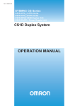
Overall System Configuration Example
The following diagram shows an example of an overall system configuration
using CS1D Ethernet Units.
Duplex Ethernet Network
A duplex Ethernet network can be created by mounting two CS1D-ETN21D
Ethernet Units as a set in a CS1D PLC.
(1) Creating a Duplex Ethernet Network
(2) Connecting the CX-Programmer to
the PLCs online via Ethernet
Duplex Ethernet Network
CX-Programmer (Ver. 4.0 or later)
FinsGateway 2003 + CS1D Ethernet unit
NS-series PT
FINS
FINS message
communications
FINS message
communications
Primary Network
Router
Secondary Network
FINS message
communications
Wireless LAN
Network status
PLC
Network status
Network status
FINS
PLC
PLC
Earlier model Ethernet Unit
FINS message
communications
Primary Unit
Secondary Unit
Primary Unit
CS1D Ethernet Unit
Secondary Unit
(4) Communicating with devices that
connect to individual Ethernet Units,
such as earlier Ethernet Units
CS1D Ethernet Unit
(3) Sending and receiving data via Ethernet
between OMRON PLCs
Non-duplex Ethernet
Network
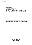
A non-duplex Ethernet network can be created by mounting one CS1DETN21D Ethernet Unit in a CS1D PLC.
(2) Connecting the CX-Programmer to the
PLCs online via individual Ethernet
Individual Ethernet Network
CX-Programmer (Ver. 4.0 or later)
FinsGateway 2003 + CS1D Ethernet unit
NS-series PT
FINS
FINS message
communications
FINS message
communications
Primary Network
Router
FINS message
communications
PLC
PLC
Wireless LAN
PLC
FINS message
communications
CS1D Ethernet Unit
FINS
CS1D Ethernet Unit
Earlier model Ethernet Unit
(6) Sending and receiving data between OMRON
PLCs via individual Ethernet network
2
Ethernet Unit Function Guide
1-1-2
Section 1-1
Determining the Objectives
Connecting the CX-Programmer to PLCs Online via Ethernet
Creating a Duplex
Ethernet Network
Use two CS1D Ethernet Units as a set.
The main Ethernet network is called the primary network and the Ethernet
Unit connected to the primary network is called the Primary Unit. The duplex
Ethernet network is called the secondary network and the Ethernet Unit connected to the secondary network is called the Secondary Unit.
Special communications data, called the network status, is broadcast at fixed
intervals in order to manage the entry/withdrawal of communications nodes in
each network. Nodes can be duplexed in the Ethernet network only if they are
within the same segment and can send and receive the broadcast network
status data.
Connecting the CXProgrammer and a PLC
Online in a Duplex
Ethernet Network
To create a redundant CX-Programmer connection, use FinsGateway Version
2003 or later as the computer’s middleware and install the Ethernet Unit driver
(ETN_UNIT) for the duplex Ethernet network.
Communicating between
OMRON PLCs in a Duplex
Ethernet Network
Applications can be constructed using the SEND, RECV, and CMND ladder
programming instructions.
Use the UDP/IP version of the FINS communications service (hereafter
referred to as FINS/UDP) as the communications method. When there is a
failure in part of the primary network’s communications path in the FINS communications service, the system automatically switches to the secondary network path to replace the failed part of the primary network only. It is possible
that communications data will be lost until communications are rerouted over
the failed part of the primary network, but this data will be sent again by the
CX-Programmer’s timeout and retry functions.
Use the UDP/IP version of the FINS communications service (hereafter
referred to as FINS/UDP) as the communications method. When there is a
failure in part of the primary network’s communications path in the FINS communications service, the system automatically switches to the secondary network path to replace the failed part of the primary network only. It is possible
that communications data will be lost until communications are rerouted over
the failed part of the primary network, but this data will be sent again if the
correct timeout and retry function settings are made in the SEND, RECV, and
CMND instructions.
We recommend allocating fixed IP addresses in computers connected to the
duplex Ethernet networks. If a protocol such as DHCP is being used, which
changes IP addresses, it is difficult to switch to the secondary network when a
failure occurs.
Communicating with Nonduplex Ethernet Nodes
such as Earlier Ethernet
Units
Connecting within the Same Segment
Use the UDP/IP version of the FINS communications service (i.e., FINS/
UDP). FINS/UDP is supported by many OMRON products and is compatible
with earlier Ethernet Units (CS1W-ETN01/ETN11 and CJ1W-ETN11). The
CX-Programmer can be connected and used with FINS/UDP even if personal
computer middleware (FinsGateway) is not used. FinsGateway (any version)
can also be used together with the CX-Programmer.
3
Ethernet Unit Function Guide
Section 1-1
Connecting through Multiple Segments
Use the TCP/IP version of the FINS communications service (i.e., FINS/TCP).
FINS/TCP is a new function supported by these Ethernet Units (CS1D-ETN21
D). It provides automatic recovery at the TCP/IP layer from communications
errors (such as packet loss) that occur during multilevel routing. To use the
CX-Programmer with FINS/TCP, use FinsGateway (version 2003 or higher) as
personal computer middleware.
Using Media with Unreliable Connections, Such as a Wireless LAN
Use the TCP/IP version of the FINS communications service (i.e., FINS/TCP).
FINS/TCP is a new function supported by these Ethernet Units (CS1WETN21 and CJ1W-ETN21). It provides automatic recovery at the TCP/IP layer
from communications errors (such as packet loss) resulting from unreliable
connections. To use the CX-Programmer with FINS/TCP, use FinsGateway
(version 2003 or higher) as personal computer middleware.
Connecting from a Personal Computer with a Dynamic Private IP
Address
Depending on whether or not the connection will be within the same segment,
either use an IP address conversion method for dynamic IP addresses in the
UDP/IP version of the FINS communications service or use the TCP/IP version of the FINS communications service.
It is possible to connect online to a PLC using the CX-Programmer from a
computer serving as a temporarily connected node or a permanent DHCP client.
To use the CX-Programmer with FINS/TCP, use FinsGateway (version 2003
or higher) as personal computer middleware.
Connecting the CXProgrammer and a PLC
Online in a Non-duplex
Ethernet Network
Connecting within the Same Segment
Use the UDP/IP version of the FINS communications service (i.e., FINS/
UDP). FINS/UDP is supported by many OMRON products and is compatible
with earlier Ethernet Units (CS1W-ETN01/ETN11 and CJ1W-ETN11). The
CX-Programmer can be connected and used with FINS/UDP even if personal
computer middleware (FinsGateway) is not used. FinsGateway (any version)
can also be used together with the CX-Programmer.
Connecting through Multiple Segments
Use the TCP/IP version of the FINS communications service (i.e., FINS/TCP).
FINS/TCP is a new function supported by these Ethernet Units (CS1WETN21 and CJ1W-ETN21). It provides automatic recovery at the TCP/IP layer
from communications errors (such as packet loss) that occur during multilevel
routing. To use the CX-Programmer with FINS/TCP, use FinsGateway (version 2003 or higher) as personal computer middleware.
Using Media with Unreliable Connections, Such as a Wireless LAN
Use the TCP/IP version of the FINS communications service (i.e., FINS/TCP).
FINS/TCP is a new function supported by these Ethernet Units (CS1WETN21 and CJ1W-ETN21). It provides automatic recovery at the TCP/IP layer
from communications errors (such as packet loss) resulting from unreliable
connections. To use the CX-Programmer with FINS/TCP, use FinsGateway
(version 2003 or higher) as personal computer middleware.
4
Section 1-2
Features
Connecting from a Personal Computer with a Dynamic Private IP
Address
Depending on whether or not the connection will be within the same segment,
either use an IP address conversion method for dynamic IP addresses in the
UDP/IP version of the FINS communications service or use the TCP/IP version of the FINS communications service.
It is possible to connect online to a PLC using the CX-Programmer from a
computer serving as a temporarily connected node or a permanent DHCP client.
To use the CX-Programmer with FINS/TCP, use FinsGateway (version 2003
or higher) as personal computer middleware.
Communicating between
OMRON PLCs in a Nonduplex Ethernet Network
Connecting within the Same Segment
Use the UDP/IP version of the FINS communications service (i.e., FINS/
UDP). Construct applications using the SEND, RECV, and CMND instructions
in the ladder program. FINS/UDP is supported by many OMRON products
and is compatible with earlier Ethernet Units (CS1W-ETN01/ETN11 and
CJ1W-ETN11).
In comparison to FINS/TCP, FINS/UDP’s protocol processing is simpler and
has some performance advantages. Another feature of FINS/UDP is the support of broadcast transmissions. On the other hand, applications such as retry
routines must be created for FINS/UDP.
Connecting through Multiple Segments
Use the TCP/IP version of the FINS communications service (i.e., FINS/TCP).
Construct applications using the SEND, RECV, and CMND instructions in the
ladder program. FINS/TCP is a new function supported by these Ethernet
Units (CS1W-ETN21 and CJ1W-ETN21). It provides automatic recovery at
the TCP/IP layer from communications errors (such as packet loss) that occur
during multilevel routing.
1-2
Features
Constructing Duplex Ethernet Networks (Duplex FINS Communications)
The CS1D-ETN21D supports duplex Ethernet networks, which could not be
created with earlier Ethernet Unit models. Duplex Ethernet networks provide
the following functions.
Duplex Ethernet Networks (Duplex FINS Communications)
Two CS1D-ETN21D Ethernet Units can be mounted in a CS1D PLC to create
a main system (Primary Unit and primary network) and a redundant system
(Secondary Unit and secondary network).
Monitoring the Entry/Withdrawal of Nodes
Network status information is delivered periodically between the communicating nodes to monitor the entry and withdrawal of nodes in the network. The
entry/withdrawal status can be read as the network participation status using
the ladder program or the CX-Programmer.
5
Section 1-2
Features
Automatic Switching of FINS Message Communications
The Secondary Unit will be used when the Primary Unit can’t be used for
some reason (failure of the Unit, disconnected cable, online unit replacement,
etc.). If FINS message applications have been created that communicate
through the primary network, the CS1D CPU Unit and CS1D Ethernet Unit will
automatically switch to the Secondary Unit as the destination node for messages. It is possible for FINS messages to be lost when operation switches to
the Secondary Unit, but a lapse in message communications can be avoided
by using timeout monitoring and retry functions in the FINS message application.
Connecting with Earlier Non-duplex Ethernet Devices (FINS Messages)
It is possible to use non-duplex Ethernet nodes in a duplex Ethernet network.
Normally, non-duplex Ethernet nodes are connected to the primary network.
The communications path is not redundant between non-duplex Ethernet
nodes, so the automatic switching function cannot be used between these
nodes.
FINS Message Communications
FINS message communications are compatible and interchangeable with earlier non-duplex Ethernet Units.
• Expandable number of nodes (up to 254 nodes max.)
• FINS/UDP protocol, which uses UDP/IP
• FINS/TCP protocol, which uses TCP/IP (Up to 16 simultaneous connections are allowed and the keep-alive function is supported.)
Network Connection to Controller Link
It is also possible to interconnect the Ethernet information network with the
Controller Link control network (using the FINS communications service functions). This feature allows a PLC in the Ethernet network to monitor a PLC in
the Controller Link network. Conversely, a PLC in the Controller Link network
can read or write data in a PLC in the Ethernet network.
Full Set of Troubleshooting Functions
A variety of functions are available so that network problems can be identified
and corrected quickly.
• Self-diagnostic functions at startup
• Check connections with other nodes using the PING command.
• Check connections with other nodes using the internode test.
• Error log function records error information when errors occur.
• E-mail notification of error events
• Online replacement of Units
6
Section 1-3
System Configuration
1-3
1-3-1
System Configuration
System Configuration
(2) Twisted-pair cable
(3) Hub
(1) CS1D Ethernet Unit
(100Base-TX)
CX-Programmer
CX-Net
FinsGateway
100 m
max.
CS1D CPU Unit
(4) Ethernet Cards for Computers
1-3-2
Devices Required for Constructing a Network
The basic configuration for a 100Base-TX Ethernet System consists of one
hub to which nodes are attached in star form using twisted-pair cable.
The devices shown in the following table are required to configure a network
with 100Base-TX-type CS1D-ETN21D Ethernet Units, so prepare them in
advance.
Network device
(1) CS-series CS1D
Ethernet Units
(CS1D-ETN21D)
Contents
These Ethernet Units are Communications Units that
connect a CS-series CS1D PLC to 100Base-TX Ethernet
networks. (They can also be used as 10Base-T.)
(2) Twisted-pair cable
This is twisted-pair cable for connecting 100Base-TX-type
Ethernet Units to the hub, with an RJ45 Modular Connector at each end.
Use a category 3, 4, 5, or 5e UTP (unshielded twistedpair) or STP (shielded twisted-pair) cable.
This is a relay device for connecting multiple nodes in a
star LAN.
Install an Ethernet card in the computer when necessary,
e.g., when creating a duplex Ethernet network.
(3) Hub
(4) Ethernet cards for
computers
Recommended Hubs
1-3-3
For details on recommended devices for constructing a network, refer to 2-5
Network Installation.
Setup Area and Related Peripheral Devices
Making I/O Table Settings
(with the CX-Programmer
or Programming Console)
Make the necessary I/O table settings for the CS1D-ETN21D Ethernet Unit as
a CPU Bus Unit. Make the settings with a Programming Console or CX-Programmer Version 4.0 or later (the I/O Table window).
7
Section 1-3
System Configuration
Personal computer
running Windows
CX-Programmer
I/O Table Setup
CS1D Ethernet Unit
I/O Table
CS1D CPU Unit
Making PLC Setup
Settings
(with the CX-Programmer
or Programming Console)
When using the CS1D-ETN21D Ethernet Units in a duplex Ethernet network,
set the Ethernet Unit as a primary or Secondary Unit. as a CPU Bus Unit.
Make the settings with a Programming Console or CX-Programmer Version
4.0 or later (the Comms Unit Duplex Tab of the PLC Setup Window).
Personal computer
running Windows
CX-Programmer
PLC Setup
CS1D Ethernet Unit
PLC Setup
CS1D CPU Unit
Making Settings in the
CPU Bus Unit System
Setup Area (with the CXProgrammer)
For the Ethernet Unit to function as a node on an Ethernet network, make the
settings, as required, in the CPU Bus Unit System Setup Area allocated in
non-volatile memory in the CPU Unit.
Use the CX-Programmer to make the settings (by connecting online from the
I/O Table Window, selecting the Ethernet Unit, and then selecting Unit Setup).
Each time the Ethernet Unit is turned ON or restarted, it reads and uses the
contents of the CPU Bus Unit System Setup Area as the settings for the communications services.
Use the CX-Programmer Version 4.0 or later to make the settings for a CS1DETN21D Ethernet Unit. It is also possible to make the settings for a CS1DETN21D without the CX-Programmer using a Programming Console and a
text file stored in a Memory Card. (Refer to Appendix F Inspections for details
on making settings from a text file in the Memory Card.)
8
Section 1-3
System Configuration
Personal computer
running Windows
CX-Programmer
Unit Setup
CS1D Ethernet Unit
CPU Bus Unit System
Setup Area
CS1D CPU Unit
Making Settings in the
Routing Table Area (with
CX-Net)
OMRON Communications Units use OMRON's original FINS network system.
Make the settings for the FINS network address and the relay path, as
required, in the Routing Table Area allocated to the non-volatile memory in the
CPU Unit.
Use CX-Net to make the settings. (CX-Net is software that comes with the
CX-Programmer and is automatically installed when the CX-Programmer is
installed.) Each time the Ethernet Unit is turned ON or restarted, it reads and
uses the contents of the Routing Table Area as the settings for FINS network.
When using a duplex Ethernet network, set different network addresses for
the primary and Secondary Units.
Personal computer
running Windows
CX-Net
Routing table
settings
CS1D Ethernet Unit
Routing Table Area
CS1D CPU Unit
Middleware for FINS
Communications
Applications on a
Personal Computer
(FinsGateway)
FinsGateway can be used as middleware when constructing communications
applications on a personal computer for a FINS network, using Visual C++ or
Visual BASIC. The CX-Programmer and CX-Net can also be connected
online through FinsGateway. When FINS/UDP is used in the FINS communications service, all versions of FinsGateway can be used.
When FINS/TCP is used in the FINS communications service, only FinsGateway Version 2003 or higher can be used.
When installing two Ethernet cards in the computer to use the duplex network
functions, an Ethernet Unit (ETN_UNIT) that supports the duplex network
functions must be included in the FinsGateway Version 2003.
FinsGateway Version 2003 or later must be used in order to connect the CXProgrammer or CX-Net online through FINS/TCP.
9
Section 1-3
System Configuration
Personal computer running Windows
User-created
software
CX-Programmer
FinsGateway
Windows
Ethernet Unit that supports
redundant networking
ETN_UNIT
CS1D Ethernet Unit
CS1D CPU Unit
10
Section 1-4
Specifications
1-4
Specifications
1-4-1
General Specifications
CS-series CS1D Ethernet
Unit
Item
Specifications
Model number
CS1D-ETN21D
Type
Applicable PLCs
100Base-TX (Can be used as 10Base-T)
CS-series CS1D PLCs
Unit classification
Mounting location
CS-series CPU Bus Unit
CPU Rack or Expansion Rack
Number of Units that can be
mounted
4 max. (including Expansion Racks)
Or 4 sets (using 2 Units as 1 set for redundant networking), including Expansion
Racks
Transfer
specifications
Media access
method
CSMA/CD
Modulation method
Transmission paths
Baseband
Star form
Baud rate
Transmission media
100 Mbit/s (100Base-TX)
Unshielded twisted-pair (UDP) cable
Categories: 5, 5e
Shielded twisted-pair (STP) cable
Categories: 100 Ω at 5, 5e
Transmission distance
100 m (distance between hub and node)
2
10 Mbit/s (10Base-T)
Unshielded twisted-pair (UDP) cable
Categories: 3, 4, 5, 5e
Shielded twisted-pair (STP) cable
Categories: 100 Ω at 3, 4, 5, 5e
Number of cascade
connections
Current consumption (Unit)
4
380 mA max. at 5 V DC
Vibration resistance
Conforms to JIS 0040.
Shock resistance
10 to 57Hz: 0.075-mm amplitude, 57 to 150 Hz: acceleration 9.8 m/s2 in X, Y, and Z
directions for 80 minutes each (sweep time: 8 minutes × 10 sweeps = 80 minutes)
Conforms to JIS 0041.
147m/s2, 3 times each in X, Y, and Z directions
Ambient operating temperature
Ambient humidity
0 to 55°C
10% to 90% (with no condensation)
Atmosphere
Ambient storage temperature
Must be free of corrosive gas.
−20 to 75°C
Weight
Dimensions
200 g max.
35 × 130 × 101 mm (W × H × D)
11
Section 1-4
Specifications
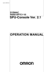
1-4-2
Dimensions
CS1D-ETN21D
ETN21D
100M
ERH
TCP
RUN
ERC
SD
RD
LNK
DPL
UNIT
NO.
0
1
×161
×160
130
NODE
NO.
0
100BASE-TX
10BASE-T
35
101
(Unit: mm)
1-4-3
Software Configuration
The software supported by the Ethernet Unit runs in the layers shown in the
following diagram. The components that form the various layers are defined
below the diagram.
CS-series CPU Unit
CS-series
CPU Unit
FINS communication service
7. FINS
8. Network Status Generator
FINS/UDP
FINS/TCP
6. TCP
5. UDP
2. IP
3. ICMP
4. ARP
Ethernet
Unit
1. Ethernet (Ver. 2.0)
1,2,3...
1. Ethernet (Ver. 2.0)
The Version 2.0 Ethernet frame format is used for communications.
2. IP (Internet Protocol)
Transfers datagrams to destination nodes using IP addresses.
3. ICMP (Internet Control Message Protocol)
Supports IP communications by signalling errors in data transfers.
4. ARP (Address Resolution Protocol)
Determines the Ethernet address (i.e., physical address) by broadcasting
based on the target IP address.
12
Section 1-5
Overview of Communications Functions
5. UDP (User Datagram Protocol)
Performs data communications with datagram units. Data resends, priority
control, flow control, and other measures to ensure communications reliability are not performed for UDP communications, so the transmitted data
may not arrive at the destination node. To increase reliability, it is necessary to program special measures into the user applications.
6. TCP (Transmission Control Protocol)
Performs communications after establishing a connection (i.e., a virtual circuit) with the destination node, providing a highly reliable communications
service.
7. FINS (Factory Interface Network Service)
A protocol that sends messages between PLCs on any of various OMRON
FA networks. To ensure that transmitted messages arrive at the destination
node, it is necessary to program special measures such as retry processing into the user's applications.
8. Network Status Generator
A proprietary OMRON protocol that monitors the entry/withdrawal of nodes
in a duplex Ethernet system.
1-5
1-5-1
Overview of Communications Functions
FINS Communications Service
Basic Functions
FINS commands can be sent to or received from other PLCs or computers on
the same Ethernet network by executing SEND(090), RECV(098), or
CMND(490) instructions in the ladder diagram program. This enables various
control operations such as the reading and writing of I/O memory between
PLCs, mode changes, and file memory operations.
Ethernet
IP UDP or TCP FINS
IP UDP or TCP FINS
CS1D CPU
Unit
CS1D
Ethernet Unit
CS1D
Ethernet Unit
CS1D
Ethernet Unit
User program
SEND(090),
RECV(098), or
CMND(490)
instruction
Executing, from the host computer, FINS commands with UDP/IP or TCP/IP
headers enables various control operations, such as the reading and writing
of I/O memory between PLCs, mode changes, and file memory operations.
For example, it is possible to connect online via Ethernet from FINS communications applications such as the CX-Programmer, and to perform remote programming and monitoring. (See note.)
Note
FinsGateway Version 2003 or higher is required to use TCP/IP.
13
Section 1-5
Overview of Communications Functions
Ethernet
IP UDP or TCP FINS
CS1D CPU
Unit
CS1D Ethernet Unit
The FINS gateway function enables access to PLCs on not only the same
Ethernet network but on various other networks, including SYSMAC LINK and
Controller Link.
1-5-2
Creating a Duplex Network
Creating a Duplex
Ethernet Network
(Redundant FINS
Communications)
Two CS1D-ETN21D Ethernet Units can be used in a CS1D PLC as a set, with
one used in the main system (Primary Unit and primary network) and the
other used in the redundant system (Secondary Unit and secondary network).
Node 3
Primary Network
Secondary Network
Node 2
Node 1
Primary Unit
Secondary Unit
CS1D Ethernet Unit
Monitoring the Entry/
Withdrawal of Nodes
Secondary Unit
CS1D Ethernet Unit
The network status information is periodically delivered between nodes in a
broadcast transmission and the entry/withdrawal status of the nodes is monitored. The entry/withdrawal status information is used in the FINS message
communications’ automatic switching function. Consequently, the range of the
duplex Ethernet network is limited to nodes that can be reached by the broadcast transmissions. The network cannot be duplicated beyond this range.
Node 3
Primary
Network
Network status
Network status
Node 1
Network Participation
System
×
Primary
Secondary
14
Primary Unit
Network Participation
System
×
Primary
Secondary
Network status
Network status
Secondary
Network
Network status
Node 2
Network Participation
System
×
×
Primary
Secondary
×
Section 1-5
Overview of Communications Functions
The entry/withdrawal status can be read as the network participation status
using the ladder program or the CX-Programmer.
Automatic Switching of
FINS Message
Communications
The Secondary Unit will be used when the Primary Unit can’t be used as the
source of FINS messages for some reason (failure of the Unit, disconnected
cable, hot-swapping of the Unit, etc.). If FINS message applications have
been created that communicate through the primary network, the CS1D CPU
Unit and CS1D Ethernet Unit will automatically switch to the Secondary Unit
as the destination node for messages.
Node 3
Primary Network
Secondary Network
2. Send through
Secondary Unit.
Node 1
Node 2
1. Primary Unit is
down.
Also, if the destination node for a FINS message is withdrawn from the network, the CS1D CPU Unit and CS1D Ethernet Unit will automatically switch to
the secondary node as the destination node for the message.
Node 3
Primary Network
Secondary Network
2. Node 2
withdrawn from
primary network.
3. Send through
secondary Unit!
Node 1
Node 2
1. First send through
primary Unit.
Network Participation
System
Primary
Secondary
It is possible for FINS messages to be lost when operation switches to the
secondary system. Use timeout monitoring and retry functions in the application in order to prevent lapses in FINS message communications.
Connecting with Earlier
Non-duplex Ethernet
Nodes (FINS Messages)
Earlier models of Ethernet nodes are not equipped with the function that
sends and receives the network status information. Consequently, the earlier
Ethernet nodes are always withdrawn from the network from the viewpoint of
the duplex Ethernet nodes. The earlier nodes are not recognized in either the
primary or secondary network, so in this case FINS messages specified in the
primary network are not automatically switched and are sent in the primary
network. Since the messages are still sent in the primary network, non-duplex
Ethernet nodes can be combined with duplex Ethernet nodes in the primary
network.
15
Section 1-5
Overview of Communications Functions
Node 3
Primary Network
Secondary Network
3. Continue sending
through primary!
2. Node 4 is not in
the primary or
secondary.
Node 2
Node 1
Network Participation
System
Primary
Secondary
16
1. First, send
through primary.
Earlier Ethernet Unit
Section 1-6
Nomenclature and Functions
1-6
Nomenclature and Functions
This section describes Ethernet Unit component names, settings, and LED
indicators.
1-6-1
Component Names
CS-series Ethernet Units
CS1D-ETN21D (100Base-TX)
Front
ETN21D
100M
ERH
TCP
RUN
ERC
SD
RD
LNK
DPL
UNIT
NO.
NODE
NO.
Indicators
Display the operating status of the Unit.
0
0
1
×161
×160
Unit Number Switch
Used to set the Ethernet Unit's unit
number in one digit hexadecimal.
Node Address Switches
Used to set the Ethernet Unit's FINS
node number in two digits hexadecimal.
100BASE-TX
10BASE-T
Ethernet Connector
Used to connect the Ethernet twisted-pair cable.
Each communications device connected to the Ethernet network is allocated
a unique Ethernet address. For the Ethernet Unit, this Ethernet address is
shown on the right side of the Unit as a 12-digit hexadecimal number.
CS1D-ETN21D
ETHERNET UNIT
Lot No.
OMRON Corporation
MADE IN JAPAN
@@@@@@@@@@@@
Ethernet Address
Ethernet address (12 digits)
17
Section 1-6
Nomenclature and Functions
Note
1. The Ethernet address can also be checked using the FINS command,
CONTROLLER DATA READ. For details, refer to 7-2-2 CONTROLLER
DATA READ on page 136.
2. An IP address label is provided with the Unit. Writing the IP address and
the subnet mask on this label and then attaching it to the front of the Unit
allows the IP address and subnet mask to be easily confirmed.
ETN21D
100M
ERH
TCP
RUN
ERC
SD
RD
LINK
DPL
Example
UNIT
NO.
IP ADDRESS
0
133.113.
NODE
NO.
0
×161
×160
255.255.255.0
IP ADDRESS
133.113.
0. 42
SUBNET MASK
1
0. 42
Attach the label to the front
of the Ethernet Unit between
the node number switches
and the Ethernet connector.
SUBNET MASK
255.255.255.0
100BASE-TX
10BASE-T
1-6-2
Indicators
The status of the indicators show the operating status of the Ethernet Unit, as
shown below.
CS1D-ETN21D
(100Base-TX)
ETN21D
RUN
ERC
SD
RD
LINK
Indicator
Color
Status
100M
ERH
TCP
DPL
Meaning
RUN
Green
Not lit
Operation stopped
Hardware error
100M
(Transfer speed)
Green
Lit
Not lit
Normal operation
10 Mbps (10Base-T)
ERC
(Ethernet Unit error)
Red
Lit
Not lit
100 Mbps (100Base-TX)
Unit normal
Lit
Node address not between 1 and 254
A hardware (e.g., internal memory) error has occurred.
18
Section 1-7
Comparison with CS1W-ETN21
Indicator
ERH
(CPU Unit error)
Color
Red
Status
Not lit
Meaning
CPU Unit normal
Lit
An error has occurred at the CPU Unit.
There is an error in the I/O table, unit number, unit setup, or routing
table settings.
An illegal IP address has been set. With automatic address generation, the rightmost two digits of the IP address do not match the
node address.
Flashing
A file access error occurred when making settings from a text file
stored in the Memory Card.
SD
(Send Data)
Yellow
Not lit
Lit
Not sending data (ready to send)
Sending data
RD
(Receive Data)
Yellow
Not lit
Lit
Not receiving data (ready to receive)
Receiving data
LNK
(Link status)
Yellow
Not lit
Lit
Link not established between hubs.
Link established between hubs.
TCP
(TCP socket in use)
Yellow
Not lit
Not lit
None of the eight TCP sockets provided for socket services is in
use.
At least one of the eight TCP sockets provided for socket services
is in use.
Duplex (redundant) network operation stopped.
Lit
Flashing
Duplex network is operating through the Primary Unit.
Duplex network is operating through the Secondary Unit.
Lit
DPL
(Duplex network operation)
1-7
Yellow
Comparison with CS1W-ETN21
Item
Previous models
New models
Model number
CS1W-ETN21
CJ1W-ETN21
CS1D-ETN21D
Duplex (redundant) network operation
(Redundant FINS message communications)
PLC maintenance via the Internet
Not Possible
Possible
Can send commands (including FINS commands) by e-mail over the Internet from a personal computer to the PLC (using the mail receive function).
Possible with the mail receive Not Possible
function.
Server specification
Specification by IP address or Not Possible
by host name (using the DNS
client function)
19
Section 1-7
Comparison with CS1W-ETN21
Item
Communi- FINS comcations ser- municavice
tions
service
Automatic IP
address acquisition (DHCP client) by personal
computer
Previous models
New models
A computer automatically acquiring IP addresses can send commands to
the PLC and receive responses.
(UDP/IP: By automatic generation (dynamic) IP address conversion
method; TCP/IP: Automatic)
FINS communi- Possible (with Automatic allocation by Ethernet Unit)
cations with per- (Client FINS automatic node address allocation function, TCP/IP only)
sonal computers
without fixed
node addresses
Handling TCP/
IP
With FINS communications, both UDP/IP and TCP/IP possible.
Simultaneous
Possible (with both UDP/IP and TCP/IP)
connection of
multiple applications in a personal computer
Mail functions
E-mail attachments with I/O
Not Possible
memory data are possible for
the mail send function. (SMTP
client function, file attachment
function)
With the mail receive function,
commands can be received
from the PLC. (POP3 client
function, mail receive function)
20
FTP server function
Large files in file memory can Not Possible
be accessed (uploaded or
downloaded) using FTP commands from FTP client software.
Socket services function
Automatic clock information
adjustment
Possible
Not Possible
CPU Unit built-in clock can be Not Possible
adjusted from SNTP server.
(SNTP client function)
SECTION 2
Installation and Initial Setup
This section explains how to install the Ethernet Unit and make the initial settings required for operation.
2-1
Overview of Startup Procedure . . . . . . . . . . . . . . . . . . . . . . . . . . . . . . . . . . . .
22
2-1-1
Duplex Ethernet Networks . . . . . . . . . . . . . . . . . . . . . . . . . . . . . . . .
22
2-1-2
Non-duplex Ethernet Networks . . . . . . . . . . . . . . . . . . . . . . . . . . . .
24
2-2
Main Points in Creating a Duplex Ethernet Network . . . . . . . . . . . . . . . . . . .
25
2-3
Switch Settings . . . . . . . . . . . . . . . . . . . . . . . . . . . . . . . . . . . . . . . . . . . . . . . .
26
2-3-1
2-4
2-5
2-6
2-7
CS-series CS1D Ethernet Units . . . . . . . . . . . . . . . . . . . . . . . . . . . .
26
Mounting to a PLC . . . . . . . . . . . . . . . . . . . . . . . . . . . . . . . . . . . . . . . . . . . . .
29
2-4-1
Mounting to a CS1D Duplex-CPU System . . . . . . . . . . . . . . . . . . .
29
2-4-2
Mounting to a CS1D Single-CPU System . . . . . . . . . . . . . . . . . . . .
29
Network Installation . . . . . . . . . . . . . . . . . . . . . . . . . . . . . . . . . . . . . . . . . . . .
30
2-5-1
Basic Installation Precautions. . . . . . . . . . . . . . . . . . . . . . . . . . . . . .
30
2-5-2
Recommended Products . . . . . . . . . . . . . . . . . . . . . . . . . . . . . . . . . .
31
2-5-3
Precautions . . . . . . . . . . . . . . . . . . . . . . . . . . . . . . . . . . . . . . . . . . . .
32
2-5-4
Using Contact Outputs (Common to All Units) . . . . . . . . . . . . . . . .
33
Connecting to the Network . . . . . . . . . . . . . . . . . . . . . . . . . . . . . . . . . . . . . . .
34
2-6-1
Ethernet Connectors . . . . . . . . . . . . . . . . . . . . . . . . . . . . . . . . . . . . .
34
2-6-2
Connecting the Cable . . . . . . . . . . . . . . . . . . . . . . . . . . . . . . . . . . . .
35
Creating I/O Tables . . . . . . . . . . . . . . . . . . . . . . . . . . . . . . . . . . . . . . . . . . . . .
36
2-7-1
I/O Table Overview. . . . . . . . . . . . . . . . . . . . . . . . . . . . . . . . . . . . . .
36
2-7-2
Connecting Programming Devices to the PLC. . . . . . . . . . . . . . . . .
36
2-7-3
Procedure for Creating I/O Tables . . . . . . . . . . . . . . . . . . . . . . . . . .
36
2-8
Enabling Duplex Communications . . . . . . . . . . . . . . . . . . . . . . . . . . . . . . . . .
37
2-9
Unit Setup Procedure . . . . . . . . . . . . . . . . . . . . . . . . . . . . . . . . . . . . . . . . . . .
39
2-10 Basic Settings . . . . . . . . . . . . . . . . . . . . . . . . . . . . . . . . . . . . . . . . . . . . . . . . .
41
2-11 Communications Test . . . . . . . . . . . . . . . . . . . . . . . . . . . . . . . . . . . . . . . . . . .
45
2-11-1 Using Indicators . . . . . . . . . . . . . . . . . . . . . . . . . . . . . . . . . . . . . . .
45
2-11-2 PING Command . . . . . . . . . . . . . . . . . . . . . . . . . . . . . . . . . . . . . . . .
46
2-12 Replacing an Ethernet Unit . . . . . . . . . . . . . . . . . . . . . . . . . . . . . . . . . . . . . . .
47
21
Section 2-1
Overview of Startup Procedure
2-1
2-1-1
Overview of Startup Procedure
Duplex Ethernet Networks
Determine the following for the Primary Unit
and the Secondary Unit.
• Local IP address
• Address conversion method
Refer to SECTION 5 Determining IP Addresses.
Set the unit numbers on the rotary switch on the
front of the Ethernet Units.
• Primary Unit: 0 to E
• Secondary Unit: Primary Unit's number + 1
(Enable using Duplex Communications Units in
the PLC Setup before setting the rotary
switches.)
Note: Always set the unit number of the
Secondary Unit to one higher than the unit
number of the Primary Unit. The following
procedure will not be valid if any other
number is set.
Set the node addresses on the rotary switches on
the front of the Ethernet Units. (This is a FINS
network setting.)
• Primary Unit: 1 to 254
• Second Unit: Set the same address as the
Primary Unit.
Mount the Units to the PLC.
*It's normally easier to mount the Primary Unit first
and then the Secondary Unit.
Connect to the network using twisted-pair cable.
*Connect to both the primary and secondary
network.
Refer to 2-3 Switch Settings.
Refer to 2-3 Switch Settings.
Refer to 2-4 Mounting to a PLC.
Refer to 2-6 Connecting to the Network.
Turn ON the power supply to the CPU Unit.
To connect without any other settings:
Use the default IP addresses, which are
as follows:
· Primary Unit:
192.168.250.node_address
· Secondary Unit:
192.168.250.node_address
To set only the IP address or to set
using only a Programming Console
(Setting is possible with either the CXProgrammer or a Programming
Console.)
To set as desired
(Setting is possible with either the CXProgrammer or a text file from a
Memory Card.)
(See note 2.)
(See note 1.)
Refer to IP Address under
2-10 Basic Settings.
Place the CX-Programmer via
Ethernet.
Create the I/O tables using the CXProgrammer.
(See note 3.)
(To next page)
22
Create the I/O tables using the CXProgrammer or a Programming Console.
Create the I/O tables using the CXProgrammer or a Programming Console.
Set the IP address in the DM Area
Set the IP address in the Unit Setup for
words allocated to the Ethernet Unit.
the Ethernet Unit.
Refer to IP Address under
2-10 Basic Settings and to
4-2 DM Area Allocations.
Refer to IP Address under 2-10 Basic Settings
and to Appendix 7 Setting Up an Ethernet Unit
Using a Memory Card Text File.
Section 2-1
Overview of Startup Procedure
(From previous page)
Enable duplex communications for the
Primary Ethernet Unit by selecting its unit
number on the Comms Unit Duplex Tab
Page of the CX-Programmer and transfer
the setting to the Unit. (Setting is also
possible with a Programming Console or
by using a text file in a Memory Card.)
(See note 2.)
Turn OFF the power supply.
• Confirm that the DPL indicator on the Primary Unit is lit.
• Confirm that the DPL indicator on the Secondary Unit is flashing.
• If the Secondary Unit is set to the default IP address, it will automatically
change to the following value at this point.
192.168.251.node_address
Change the unit number of the
Secondary Unit.
• Secondary Unit:
Same as the Primary Unit.
Turn ON the power supply.
(See note 4.)
Create routing tables with the CXProgrammer.
(See note 2.)
Refer to 6-4 Creating Routing Tables.
(Routing tables must be set when using a Duplex Ethernet Network.
Make the other settings from the CXProgrammer, such as the IP router table.
(Setting is also possible using a text file
in a Memory Card.)
Refer to SECTION 3 CX-Programmer Unit Setup, IP Router Table in
2-10 Basic Settings, and Appendix 7 Setting Up an Ethernet Unit
Using a Memory Card Text File.
Check the status of communications
using the SD and RD indicators or PING
command.
Refer to 2-11 Communications Test.
Note
(1) Used mainly when setting the IP address using only a Programming Console (i.e., setting it in the words allocated in the DM Area). When using
this method, the IP address in the Unit Setup must be at the default value
of 00.00.00.00. If any other value is set in the Unit Setup it will be given
priority over the setting in the DM Area and the setting in the DM Area will
be changed.
(2) Setting is possible with CX-Programmer version 4.0 or higher or a Memory Card text file. A Memory Card text file is normally used when CX-Programmer version 4.0 or higher is not available. Refer to Appendix G Using
a Memory Card Text File to Set Up an Ethernet Unit for details.
(3) A PLC Programming Device, such as the CX-Programmer, the CX-Net,
or a Programming Console, is required.
(4) The CX-Net is required.
23
Section 2-1
Overview of Startup Procedure
2-1-2
Non-duplex Ethernet Networks
Determine the following for each Ethernet Unit.
• Local IP address
• Address conversion method
Refer to SECTION 5 Determining IP Addresses.
Refer to 2-3 Switch Settings.
Set the unit number.
• Unit number: 0 to F
Refer to 2-3 Switch Settings.
Set the node address.
• Node address: 1 to 2
Refer to 2-4 Mounting to a PLC.
Mount the Units to the PLC.
Connect to the network using twisted-pair cable.
Refer to 2-6 Connecting to the Network.
Turn ON the power supply to the CPU Unit.
To connect without any other settings:
To set only the IP address or to set
using only a Programming Console
(Setting is possible with either the CXProgrammer or a Programming
Console.)
Use the default IP address, which is as
follows:
192.168.250.node_address
Refer to IP Address under
2-10 Basic Settings.
Place the CX-Programmer via
Ethernet.
Create the I/O tables using the CXProgrammer.
(See note 2.)
(See note 1.)
Create the I/O tables using the CXProgrammer or a Programming Console.
Create the I/O tables using the CXProgrammer or a Programming Console.
Set the IP address in the DM Area
Set the IP address in the Unit Setup for
words allocated to the Ethernet Unit.
the Ethernet Unit.
Refer to IP Address under
2-10 Basic Settings and to
4-2 DM Area Allocations.
Refer to IP Address under 2-10 Basic
Settings and to Appendix 7 Setting Up
an Ethernet Unit Using a Memory Card
Text File.
(See note 3.)
Required only for the following:
• Using the FINS communications service
• Using the SEND, RECV, or CMND
instruction on a PLC with more than one
Communications Unit.
Create routing tables with the CXProgrammer.
(See note 2.)
Refer to 6-4 Creating Routing Tables.
Make the other settings from the CXProgrammer, such as the IP router table.
(Setting is also possible using a text file
in a Memory Card.)
Refer to SECTION 3 CX-Programmer Unit Setup, IP Router Table in
2-10 Basic Settings, and Appendix 7 Setting Up an Ethernet Unit
Using a Memory Card Text File.
Check the status of communications
using the SD and RD indicators or PING
command.
Refer to 2-11 Communications Test.
Note
24
To set as desired
(Setting is possible with either the CXProgrammer or a text file from a
Memory Card.)
(1) Used mainly when setting the IP address using only a Programming Console (i.e., setting it in the words allocated in the DM Area). When using
this method, the IP address in the Unit Setup must be at the default value
of 00.00.00.00. If any other value is set in the Unit Setup it will be given
priority over the setting in the DM Area and the setting in the DM Area will
be changed.
Section 2-2
Main Points in Creating a Duplex Ethernet Network
(2) Setting is possible with CX-Programmer version 4.0 or higher or a Memory Card text file. A Memory Card text file is normally used when CX-Programmer version 4.0 or higher is not available. Refer to Appendix G Using
a Memory Card Text File to Set Up an Ethernet Unit for details.
(3) A PLC Programming Device, such as the CX-Programmer, the CX-Net,
or a Programming Console, is required.
(4) The CX-Net is required.
2-2
Main Points in Creating a Duplex Ethernet Network
POINT 1: Initially set the
unit number of the
Secondary Unit to one
higher than that of the
Primary Unit
Before creating the I/O tables, set the unit number of the Secondary Unit to
one higher than that of the Primary Unit and maintain this setting until duplex
communications have been enabled in the PLC Setup. After enabling duplex
communications in the PLC Setup, set the Primary Unit and Secondary Unit
to the same unit number.
Primary Second
Unit
Unit
UNIT
No.
Unit No. = A
(Example: 0)
Note
POINT 2: Set the same
node address for both the
Primary Unit and
Secondary Unit
Unit No. = A+1
(Example: 1)
The unit number that was set for the Secondary Unit before enabling duplex
communications cannot be used after duplex communications have been
enabled in the PLC Setup. For example, if the Primary Unit is initially set to
unit number 1 and the Secondary Unit is initially set to unit number 2, unit
number 2 cannot be used for the Secondary Unit after enabling duplex communications.
The same node address is set for the Primary Unit and Secondary Unit from
the beginning and does not need to be changed.
Primary
Unit
NODE
No.
161
160
Node address = A
(Example: 14)
POINT 3: Enable Duplex
Communications in the
PLC Setup
UNIT
No.
Secondary
Unit
NODE
No.
161
160
Node address = A
(Example: 14)
After creating the I/O tables, enable duplex communications by selecting the
unit number of the Primary Ethernet Unit on the Comms Unit Duplex Tab
Page of the CX-Programmer (CS1D Communications Unit @).
25
Section 2-3
Switch Settings
After making the above setting, transfer the settings to the Unit.
POINT 4: After enabling
duplex communications,
change the unit number of
the Secondary Unit to the
unit number set for the
Primary Unit
After enabling duplex communications, change the unit number of the Secondary Unit to the same unit number as the one set for the Primary Unit
Primary
Unit
UNIT
No.
Unit number = A
(Do not change.)
(Example: 0)
Note
Secondary
Unit
UNIT
No.
Change unit number from A+1 to A
(Example: Change from 1 to 0.)
(1) Always use the procedure given in 2-3 Switch Settings to set the unit
number. Duplex operation will not be possible for the Ethernet Units if this
procedure is not used.
(2) Always create the I/O tables before enabling duplex communications in
the PLC Setup. Duplex operation will not be possible if duplex communications are enabled before creating the I/O tables.
POINT 5: If the unit
number of the Primary
Unit or Secondary Unit is
changed, redo the duplex
setup procedure
2-3
2-3-1
If the unit number of the Primary Unit or Secondary Unit is changed, redo the
duplex setup procedure from the point where the unit number of the Secondary Unit is set one higher than that of the Primary Unit.
Switch Settings
CS-series CS1D Ethernet Units
Setting the Unit Number
When using Duplex Ethernet Units, always use the following procedure to set
Unit swtiches.
26
Section 2-3
Switch Settings
1,2,3...
1. Before creating the I/O tables and before enabling duplex communications
in the PLC Setup, set the unit number of the Secondary Unit to one higher
than that of the Primary Unit.
Primary
Unit
UNIT
No.
Unit number = A
(Example: 0)
Secondary
Unit
UNIT
No.
Unit number = A + 1
(Example: 1)
2. Create the I/O tables.
3. Enable duplex communications in the PLC Setup.
4. Set the unit number of the Secondary Unit to the same value as the Primary Unit. (Do not change the unit number of the Primary Unit.)
Primary
Unit
UNIT
No.
Unit number = A
(Do not change.)
(Example: 0)
Secondary
Unit
UNIT
No.
Change unit number from A+1 to A
(Example: Change from 1 to 0.)
Do not set the same unit number for more than one CPU Bus Unit mounted in
the same PLC. Use a small flat-blade screwdriver to make the setting, being
careful not to damage the rotary switch. The factory setting is 0.
Setting range:
Duplex
Non-duplex
Note
0 to E
0 to F
(1) Turn OFF the power supply before setting the unit number.
(2) If the unit number is being set for the first time or changed, then I/O tables
must be created for the PLC.
(3) Always use the above procedure to set the unit number. Duplex operation
will not be possible for the Ethernet Units if this procedure is not used.
The unit number of the Secondary Unit must be one higher than that of
the Primary Unit before duplex communications are enabled and the unit
numbers must be the same after duplex communications are enabled.
(4) To change the unit number, clear the I/O table and then repeat the unit
number setting procedure from the beginning.
27
Section 2-3
Switch Settings
(5) Enabled duplex communications in the PLC Setup after creating the I/O
tables. Duplex operation will not be possible if duplex communications
are enabled before creating the I/O tables.
(6) With CS-series PLCs, words are automatically allocated in the CIO Area
and DM Area according to the unit numbers that are set. For details, refer
to SECTION 4 Ethernet Unit Memory Allocations.
Setting the Node Address
With the FINS communications service, when there are multiple Ethernet
Units connected to the Ethernet network, the Ethernet Units are identified by
node addresses. Use the node address switches (NODE NO.) to set the node
address between 01 and FE hexadecimal (1 to 254 decimal). Do not set a
number that has already been set for another node on the same network.
When using Duplex Ethernet Units, set the same node address for the Primary Unit and Secondary Unit. If a pair of Duplex Units are set to different
node addresses and then duplex communications are enabled in the PLC
Setup, a Duplex Verification error (non-fatal) will occur and the ERR/ALM indicator will flash. Refer to 2-8 Enabling Duplex Communications for the procedure to enable duplex communications.
If the same node address is used for two different Ethernet Units on the same
Ethernet line with Duplex Ethernet Units, the node that attempts to enter the
network last will not function in the network participation status (which is vital
to duplex network operation) and it will not participate in the network.
×161
×160
Setting range:
01 to FE (1 to 254 decimal)
The left switch sets the sixteens digit (most significant digit) and the right
switch sets the ones digit (least significant digit). The node address is factoryset to 01.
Note
(1) Turn OFF the power supply before setting the node address.
(2) Always set the same node address for the Secondary Unit and Primary
Unit.
Relation to IP Addresses
28
When using the automatic generation method (either dynamic or passive) for
address conversion, set the rightmost byte of the IP address set for the Ethernet Unit to the same value as the node address. If this is not possible, either
the IP address table method or the combined method must be used for
address conversion. (For details, refer to 5-2 IP Addresses in FINS Communications.) If the FINS communications service is not used on the Ethernet network, then it is all right to overlap with other Ethernet Units. The setting,
however, must be made within a range of 01 to FE. If a value outside of this
range is set, the ERC indicator will light.
Section 2-4
Mounting to a PLC
2-4
2-4-1
Mounting to a PLC
Mounting to a CS1D Duplex-CPU System
Ethernet Units can be mounted to any slots in either a CS1D Duplex-CPU
System CPU Rack or an Expansion CPU Rack for Online Unit Replacement.
Up to four CS1D Ethernet Units or four pairs of Duplex CS1D Ethernet Units
can be mounted to a single PLC. If it is mounted in combination with other
CPU Bus Units (e.g., Controller Link Units), the maximum total number of
CPU Bus Units that can be mounted is 16.
Tighten PLC Backplane mounting screws to a torque of 0.9 N⋅m, and the
Unit’s screws to a torque of 0.4 N⋅m.
Note
PS
CPU
CPU Backplane for Duplex-CPU System
CS1D-BC052
Can mount to any
position, with 8 slots.
5 slots
PS
Expansion Backplane for Online Unit Replacement
CS1D-BI092
Up to four Units or four pairs of
Duplex Units can be mounted to
the slots shown in the diagrams
on the left.
Can mount to any
position, with 9 slots.
9 slots
Note
2-4-2
The CS1D-ETN21D CS1D Ethernet Unit’s maximum current consumption is
380 mA. Make sure that the total current consumption of all the Units connected to the same CPU Backplane or Expansion Backplane does not exceed
the output capacity of the Power Supply Unit.
Mounting to a CS1D Single-CPU System
Ethernet Units can be mounted to any slots in either a CS1D Single-CPU System CPU Rack or an Expansion CPU Rack for Online Unit Replacement. Up
to four CS1D Ethernet Units or four pairs of Duplex CS1D Ethernet Units can
be mounted to a single PLC. If it is mounted in combination with other CPU
Bus Units (e.g., Controller Link Units), the maximum total number of CPU Bus
Units that can be mounted is 16.
Note
Tighten PLC Backplane mounting screws to a torque of 1.2 N⋅m, and the
Unit’s screws to a torque of 0.8 N⋅m.
29
Section 2-5
Network Installation
PS
CPU
CPU Backplane for Single-CPU System
CS1D-BC082S
Can mount to any
position, with 8 slots.
8 slots
PS
Expansion Backplane for Online Unit Replacement
CS1D-BI092
Up to four Unit or four pairs of
Duplex Units can be mounted to
the slots shown in the diagrams
on the left.
Can mount to any
position, with 9 slots.
9 slots
PS: Power Supply Unit
CPU: CPU Unit
Note
2-5
2-5-1
The CS1D-ETN21D CS1D Ethernet Unit’s maximum current consumption is
380 mA. Make sure that the total current consumption of all the Units connected to the same CPU Backplane or Expansion Backplane does not exceed
the output capacity of the Power Supply Unit.
Network Installation
Basic Installation Precautions
• Take the greatest care when installing the Ethernet System, being sure to
follow ISO 8802-3 specifications. You must obtain a copy of these specifications and be sure you understand them before attempting to install an
Ethernet System. Unless you are already experienced in installing communications systems, we strongly recommend that you employ a professional to install your system.
• Do not install Ethernet equipment near sources of noise. If noise-prone
environments are unavoidable, be sure to take adequate measures
against noise interference, such as installing network components in
grounded metal cases, using optical links in the system, etc.
30
Section 2-5
Network Installation
2-5-2
Recommended Products
The following products are recommended for use with the CS1D-ETN21D
CS1D Ethernet Unit.
Part
Hub
Maker
Model
number
100Base-TX
PHOESWITCH
NIX
5TX
CONTACT
Allied
Telesis
RH509E
Specifications
5-port hub
Note Suitable for FA
environments.
CenterCOM FS705EL
(5 port hub)
Note Suitable for OA
environments.
10Base-T
Allied
RH509E
Telesis
MR820TLX
Inquires
9-port hub
Note Suitable for OA
environments.
Allied Telesis
(0120) 86-0442
(in Japan only)
Allied Telesis
(0120) 86-0442
(in Japan only)
9-port hub with 10Base-5
backbone port
Note Suitable for OA
environments.
Twisted-pair
cable
100Base-TX
Fujikura F-LINK-E
0.5mm x 4P
Fujikura
CTP-LAN5
0.5mm x 4P
STP (shielded twistedpair) cable: Category 5,
5e
---
Note Impedance is limited to 100 Ω.
UTP (unshielded twistedpair) cable: Category 5,
5e
10Base-T
Fujikura
Fujikura
Connectors
(Modular
plug)
F-LINK-E
0.5mm x 4P
CTP-LAN5
0.5mm x 4P
STP (shielded twistedpair) cable: Category 3,
4, 5, 5e
Note Impedance is limited to 100 Ω.
UTP (unshielded twistedpair) cable: Category 3,
4, 5, 5e
STP Plug
Panduit
Corp
MPS588
UTP Plug
Panduit
MP588-C
Corp
---
---
31
Section 2-5
Network Installation
2-5-3
Precautions
Precautions on Laying Twisted-pair Cable
Basic Precautions
• Press the cable connector in firmly until it locks into place at both the hub
and the Ethernet Unit.
• After laying the twisted-pair cable, check the connection with a 10Base-T
cable tester.
Environment Precautions
• The UTP cable is not shielded, and the hub is designed for use in OA
environments. In environments subject to noise, construct a system with
shielded twisted-pair (STP) cable and hubs suitable for an FA environment.
• Do not lay the twisted-pair cable together with high-voltage lines.
• Do not lay the twisted-pair cable near devices that generate noise.
• Do not lay the twisted-pair cable in locations subject to high temperatures
or high humidity.
• Do not lay the twisted-pair cable in locations subject to excessive dirt and
dust or to oil mist or other contaminants.
Hub Installation
Environment Precautions
• Do not install the hub near devices that generate noise.
• Do not install the hub in locations subject to high temperatures or high
humidity.
• Do not install the hub in locations subject to excessive dirt and dust or to
oil mist or other contaminants.
Hub Connection Methods
If more hub ports are required, they can be added by connecting more than
one hub. There are two possible connection methods for hubs: Cascade and
stacked.
Cascade Connections
• Connect two hubs to each other as follows: Connect an MDI port to an
MDI-X port with a straight cable; connect two MDI ports with a cross
cable; and connect two MDI-X ports with a cross cable.
Note
It is very difficult to distinguish cross cables and straight cables by appearance. Incorrect cables will cause communications to fail. We recommend
using cascade connections with straight cables whenever possible.
• With cascade connections, up to 5 segments can be connected using up
to 4 repeaters (i.e., 4 hubs).
MDI ports
MDI-X port
(cross)
Hub
32
Straight cable
Cross cable
Hub
Hub
Hub
Section 2-5
Network Installation
Stack Connections
• Connect the hubs using special cables or special racks.
• Normally there is no limit to the number of hubs in a stack, and each stack
is treated as one hub. Some hubs, however, are limited in the number of
hubs per stack.
Hub
Four stackable hubs
Two stackable hubs
Stack cable
Stack cable
2-5-4
Using Contact Outputs (Common to All Units)
Communications errors can occur when Contact Output Units are mounted to
the same Rack or connected to the same PLC as an Ethernet Unit due to
noise generated by the contact outputs. Use one or more of the following
measures when installing Contact Output Units and Ethernet Units on the
same Rack.
Mounting Location
Mount (or connect) any Contact Output Units as far away from the CS1D
Ethernet Unit as possible.
Contact Output Unit
Ethernet Unit
Contact outputs
Cable Location
Separate the transceiver cable or twisted-pair cable connecting the CS1D
Ethernet Unit as far from the wiring to the Contact Output Units as possible.
The coaxial cable must also be placed as far away from the Contact Output
Units and their wiring as possible.
Contact outputs
Ethernet Unit
Contact Output Unit
To hub
33
Section 2-6
Connecting to the Network
Hub Measures
Attach several ferrite cores designed for EMI countermeasures on the transceiver cable or twisted-pair cable near the hub. The transceiver must also be
placed as far away from the Contact Output Units and their wiring as possible.
Ethernet Unit
Ferrite core
Hub
Twisted-pair
cable
2-6
2-6-1
Connecting to the Network
Ethernet Connectors
The following standards and specifications apply to the connectors for the
Ethernet twisted-pair cable.
• Electrical specifications: Conforming to IEEE802.3 standards.
• Connector structure:
34
RJ45 8-pin Modular Connector
(conforming to ISO 8877)
Connector pin
Signal name
1
Transmission data +
Abbr.
TD+
Signal direction
Output
2
3
Transmission data –
Reception data +
TD–
RD+
Output
Input
4
5
Not used.
Not used.
-----
-----
6
7
Reception data –
Not used.
RD–
---
Input
---
8
Not used.
---
---
Hood
Frame ground
FG
---
Section 2-6
Connecting to the Network
2-6-2
Connecting the Cable
!Caution Turn OFF the PLC’s power supply before connecting or disconnecting twistedpair cable.
!Caution Allow enough space for the bending radius of the twisted-pair cable as shown
in below.
35mm
1,2,3...
1. Lay the twisted-pair cable.
2. Connect the cable to the hub. Be sure to press in the cable until it locks into
place. A simple installation example for these first two steps is provided in
an appendix at the end of this manual.
Request cable installation from a qualified professional.
3. Connect the cable to the connector on the CS1D Ethernet Unit. Be sure to
press in the cable until it locks into place.
RJ45 Modular Connector
Ethernet Unit
35
Section 2-7
Creating I/O Tables
2-7
2-7-1
Creating I/O Tables
I/O Table Overview
I/O tables are used to identify Units mounted to the PLC, and to allocate I/O to
them. With CS-series CS1D PLCs, whenever there is a change to the Unit
configuration it is necessary to create I/O tables and register the Units to the
CPU Unit.
The I/O tables can be created in the following ways.
• Using the CX-Programmer offline.
• Using the CX-Programmer online, with the Units mounted to the PLC.
• Using the Programming Console, with the Units mounted to the PLC.
Note
(1) Before creating the I/O tables, always set the unit number of the Secondary Unit to one higher than that of the Primary Unit.
(2) Always use the procedure given in 2-3 Switch Settings to set the unit
number. Duplex operation will not be possible for the Ethernet Units if this
procedure is not used.
(3) Always create the I/O tables before enabling duplex communications in
the PLC Setup. Duplex operation will not be possible if duplex communications are enabled before creating the I/O tables.
2-7-2
Connecting Programming Devices to the PLC
To create the I/O tables, connect a Programming Device (such as a CX-Programmer or Programming Console) to the PLC.
Applicable Programming
Devices
The following Programming Devices can be used with CS-series CS1D PLCs.
Programming Console
Model number
C200H-PRO27-E
Key Sheet (required)
CS1W-KS001-E
CQM1-PRO01-E
CQM1H-PRO01-E
Recommended cable (required)
CS1W-CN224 (cable length: 2.0 m)
CS1W-CN624 (cable length: 6.0 m)
CS1W-CN114 (cable length: 0.1 m)
CX-Programmer and CX-Net (Version 4.0 or higher)
Model number: WS02-CXPC1-EV4
The operations are explained here using a Programming Console. For details
regarding the CX-Programmer and the CX-Net, refer to the CX-Programmer
User’s Manual.
CX-Net is software that comes with CX-Programmer and is automatically
installed when CX-Programmer is installed.
Connecting Programming
Devices
2-7-3
To connect a Programming Console, attach a CS/CJ-series Key Sheet and
then connect the Console to the CPU Unit’s peripheral port. (It cannot be connected to the RS-232C port.)
Procedure for Creating I/O Tables
The procedure for creating I/O tables is shown here, taking as an example I/O
tables that is generated automatically for a PLC connected online. In this
example, a Programming Console is used for creating the I/O tables. For an
explanation of how to create I/O tables using a CX-Programmer, refer to the
CX-Programmer User’s Manual.
36
Section 2-8
Enabling Duplex Communications
Use the following procedure to create the I/O tables.
Initial screen
SHIFT
CH
*DM
000000 I/O TBL ?
CHG
000000 I/O TBL
WRIT
????
WRITE
Password
000000CPU BU ST?
0:CLR 1:KEEP
or
(Save or clear the CPU Bus Unit System Setup.)
000000 I/O TBL
WRIT OK
2-8
Enabling Duplex Communications
To use Duplex Ethernet Units, duplex communications must be enable in the
PLC Setup for the Ethernet Units registered in the I/O tables. The PLC Setup
can be set with CX-Programmer version 4.0 or higher. The CX-Programmer
procedure for enabling duplex communications is given below.
Note
Before creating the I/O tables, always set the unit number of the Secondary
Unit to one higher than that of the Primary Unit.
1,2,3...
1. Place the CX-Programmer online with the PLC. Use one of the following
methods to connect the CX-Programmer to the PLC.
• Used a serial cable to connect the computer running CX-Programmer
to the peripheral port or RS-232C port on the CPU Unit.
• Connect the computer and PLC Unit Ethernet.
When Ethernet Unit information is registered in the PLC’s I/O tables,
the Ethernet Units will operate using the default IP addresses:
Primary Unit: 192.168.250.node_address
Secondary Unit: 192.168.251.node_address
These default addresses can be used to connect via Ethernet.
Refer to the manual for the CX-Programmer for instructions on connecting
with a serial cable. Refer to 6-5 Using FINS Applications for instructions on
connecting the CX-Programmer to the PLC via the Ethernet Unit.
2. Double-click the Settings Icon from the Project Window (or use the popup menu to open the settings).
37
Enabling Duplex Communications
Section 2-8
3. Click the Comms Unit Duplex Tab and select the CS1D Communications
Unit with the unit number of the Primary Ethernet Unit.
4. Transfer the PLC Setup to the PLC. Click the Yes Button in the following
dialog box.
5. Turn OFF the power supply to the PLC.
6. Set the unit number of the Secondary Unit to the same number as that of
the Primary Unit.
7. Turn ON the power to the PLC.
Note
(1) Before creating the I/O tables, always set the unit number of the Secondary Unit to one higher than that of the Primary Unit.
(2) Always use the procedure given in 2-3 Switch Settings to set the unit
number. Duplex operation will not be possible for the Ethernet Units if this
procedure is not used.
(3) Always create the I/O tables before enabling duplex communications in
the PLC Setup. Duplex operation will not be possible if duplex communications are enabled before creating the I/O tables.
38
Section 2-9
Unit Setup Procedure
2-9
Unit Setup Procedure
Use the CX-Programmer (Ver. 4.0 or higher) for the CS1D Ethernet Unit
Setup, and follow the procedure described below.
1,2,3...
1. Connect the CX-Programmer online.
The CX-Programmer can be connected to the PLC in either of the following
ways:
a. Connect the personal computer to the PLC by serial cable, through either a peripheral port or RS-232C port.
b.
Connect the personal computer to the PLC by Ethernet.
When Ethernet Unit is registered in the I/O tables in the CPU Unit, the
Ethernet Unit will operate using the default IP address (Primary Unit:
192.168.250.node_number, Secondary Unit: 192.168.251.node_number).
This default IP address can be used initially to connect online.
For details on connecting the CX-Programmer to the PLC by serial cable,
refer to the CX-Programmer operation manual.
For details on connecting the CX-Programmer to the PLC by Ethernet, refer to 6-5 Using FINS Applications.
2. Use the mouse to select I/O table in the Project Window. Either doubleclick or right-click to display the Properties Menu, and select Open. The
I/O Table Window will then be displayed.
39
Unit Setup Procedure
Section 2-9
3. Read the I/O tables from the PLC and select the Rack to which the CS1D
Ethernet Unit is mounted.
4. Move the cursor to the Ethernet Unit and right-click. Select Unit Setup from
the popup menu to display the window for making the Ethernet Unit Setup.
The default settings are shown below.
At the point where the Ethernet Unit is mounted and the I/O tables has just
been created, the default values are in effect for all of the settings.
40
Section 2-10
Basic Settings
5. Make the required settings (i.e., the IP address in this case).
6. Transfer the settings to the PLC.
Click on Yes in the following dialog box.
7.
In order for the Ethernet Unit Setup to go into effect, the Unit must be restarted.
Click on Yes in the following dialog box.
8. Check the Ethernet Unit's LED indicators.
After the RUN indicator has turned OFF and then turned ON again, the
Ethernet will recognize the new settings (i.e., the IP address in this case).
2-10 Basic Settings
The following items comprise the basic settings in the Ethernet Unit
(100Base-TX) setup. Each item is described in detail below.
• IP address
• Subnet mask
• Broadcast settings
• Baud rate
• TCP/IP keep-alive
• IP router table
41
Section 2-10
Basic Settings
■ IP Address
For the IP address, set the Ethernet Unit's local IP address.
Depending on the value that is set, the IP address has a great influence on
the connectability of the Ethernet Unit. To make full use of the Ethernet functions, it is necessary to study the applications and network system design
when determining IP address allocations. Before setting the IP address, refer
to SECTION 5 Determining IP Addresses.
There are several ways to set IP addresses.
Default Setting
The Ethernet Unit operates using the default IP address when the Unit is
mounted to the PLC and initially registered in the I/O tables (i.e., when the
Unit settings have not been made and the IP Address Display/Setting in the
CPU Bus Unit Words Allocated in the DM Area is still all zeros).
The default IP address is determined as follows:
Duplex Ethernet Networks:
Default IP address = 192.168.250.FINS node address
Default IP address = 192.168.251.FINS node address
Non-Duplex Ethernet Networks:
Default IP address = 192.168.250.FINS node address
The FINS node address is set by the rotary switch on the front of the Ethernet
Unit. If the defaults are used for the IP address and the Unit settings, the settings will be as shown below.
Item
Operation status
IP address
Subnet mask
192.168.250.FINS node address
255.255.255.0 (Class C mask)
Broadcast settings
Baud rate
4.3BSD
Auto
TCP/IP keep-alive
IP router table
120 min.
None (IP router not enabled)
Setting the IP Address in the CPU Bus Unit Words Allocated in the DM
Area
This method sets the IP address in the IP Address Display/Setting Area in the
CPU Bus Unit Words Allocated in the DM Area, when the IP address is not set
in the Unit Setup. When the IP address is set in the Unit Setup, the IP Address
Display/Setting Area becomes the area for displaying the settings.
To make settings in the IP Address Display/Setting Area, use the CX-Programmer or Programming Console to write the values. In order for the new
settings to go into effect, either the Ethernet Unit must be restarted or the
power must be turned ON again to the PLC.
15
m+98
m+99
14
13
(1)
(5)
12
11
10
(2)
(6)
9
8
7
6
5
(3)
(7)
IP address: (1)(2).(3)(4).(5)(6).(7)(8) (hexadecimal)
42
4
3
2
1
(4)
(8)
0
Section 2-10
Basic Settings
If only the IP address is set, according to the IP Address Display/Setting Area,
and the defaults are used for all other Unit settings, the settings will be as
shown below.
IP address
Item
Status
Words allocated for CPU Bus Unit (m+98 to m+99)
Subnet mask
Broadcast settings
Uses value corresponding to IP address class.
4.3BSD specifications
Baud rate
TCP/IP keep-alive
Auto
120 minutes
IP router table
Not set. (IP routing not supported.)
Unit Setup
This method sets the IP address by first selecting the Ethernet Unit from the
CX-Programmer's I/O Table Window while connected online, and then setting
the IP address from the Unit Setup.
Example: Using the CX-Programmer to Set the IP Address to 10.3.65.1
When an IP address is set in the Unit Setup, that value is displayed in the IP
Address Display/Setting Area in the DM Area words allocated for CPU Bus
Units.
When the IP address is set by the CX-Programmer, and the defaults are used
for all other Unit settings, the settings will be as shown below.
Item
IP address
Status
Set by CX-Programmer.
Subnet mask
Broadcast settings
Uses value corresponding to IP address class.
4.3BSD specifications
Baud rate
Auto
TCP/IP keep-alive
IP router table
120 minutes
Not set. (IP routing not supported.)
■ Subnet Mask
For the subnet mask, all bits corresponding to the bits in the IP address used
as either the net number or the subnet number are set to 1, and the bits corresponding to the host number are set to 0. These settings must be made when
using an address conversion method other than the IP address table method.
43
Section 2-10
Basic Settings
If no subnet mask is set, or if an illegal value is set, the following values will be
used depending on the IP address class.
Class
Class A
Subnet mask
255.0.0.0
Class B
Class C
255.255.0.0
255.255.255.0
With the default setting (0.0.0.0), a subnet mask corresponding to the IP
address class is used.
■ Broadcast Settings
Set the method for specifying IP addresses when broadcasting.
Setting
All 1 (4.3BSD)
(Default)
All 0 (4.2BSD)
Contents
Broadcast with all ones for Host ID (4.3BSD specifications).
Broadcast with Host ID all zeros (4.2BSD specifications).
■ Baud Rate
Set the baud rate.
Setting
Contents
Auto (Default)
Automatically detects the baud rate between hubs.
Operates with 100Base-TX (full duplex) whenever possible.
10Base-T
Operates with 10Base-T (half duplex).
■ TCP/IP Keep-alive Setting
Set the Liveness-Checking Interval. (This setting is enabled only when FINS/
TCP or TCP/IP socket services are used.)
When the keep-alive function is used with FINS/TCP or TCP/IP socket services, the keep-alive communications frame is used to check the status of the
connection with the remote node (either a server or client) if there are no communications during the time interval set here. Up to nine checks are executed
at 75-second intervals, and if there is no response to any of them then the
connection is terminated.
The original setting may not be appropriate for all control system applications.
When the prescribed value is used as is, it may not be suitable for control system applications. Set the checking time as required for the system. The setting range is 0 to 65,535 minutes.
■ IP Router Table
An IP router table is a table of correspondences for finding IP addresses for
the IP routers that relay target segments when the Unit communicates via IP
routers with nodes on other IP network segments.
130.25.X.X (Network ID)
Node A
130.26.X.X (Network ID)
130.25.36.253
130.26.2.254
Node B
IP router
For the IP network address, set the network number (i.e., the net ID) of the
other IP network segment with which communications are to be executed.
The length of the network number (i.e., the number of bytes) will vary depending on the IP address class. Four bytes are reserved for setting the IP network
address, so set the network number from the beginning and then set 00 in the
remaining space.
44
Section 2-11
Communications Test
A maximum of eight settings can be registered. The default is for nothing to be
set.
Settings
In this example setting for Node A (refer to the diagram above), a network with
a Network ID of 130.26.XX is connected to an IP router with an IP address of
130.25.36.253.
Only one default IP router can be set.
The default IP router is selected when no Network ID exists in the IP router
table for the destination network number. To set the default IP router, set
0.0.0.0 for the IP address and set the default IP router's IP address for the
router address.
2-11 Communications Test
2-11-1 Using Indicators
LNK Indicator
The LNK indicator will light when communications are possible between the
Ethernet Unit and hub. This indicator can thus be used to determine if there
are any faults or faulty connections in the Units, cables, and hub.
100M Indicator
Once the LNK indicator is lit, the 100M indicator can be used to determine the
baud rate. The default setting of the baud rate of the Ethernet Unit is set to
automatically detect the network baud rate. If 100Base-TX is detected, the
100M indicator will light. If 10Base-T is detected, the 100M indicator will not
light. The Ethernet Unit can be set either to detect the baud rate or to use
10Base-T.
DPL Indicator
The DPL indicator will light when the Ethernet Unit is set for duplex communications. Use it to confirm this duplex settings.
DPL Indicator: Lit
The Ethernet Unit is set as the Primary Unit for duplex operation.
DPL Indicator: Not Lit
The Ethernet Unit is set as the Secondary Unit for duplex operation.
DPL Indicator: Flashing
The Ethernet Unit is set for non-duplex operation.
SD and RD Indicators
If Ethernet Units are being used for a duplex network, network status will be
broadcast periodically. The SD and RD indicators will flash when network status is broadcast.
SD and RD Indicators: Flashing
The Ethernet Unit is participating normally in the network.
45
Section 2-11
Communications Test
SD Indicator: Flashing, RD Indicator: Not Lit
The Ethernet Unit is not participating normally in the network. Check for other
Ethernet Units set for duplex operation in the same network and check the
communications path (Units, cables, and hub).
SD and RD Indicators: Not Lit
The Ethernet Unit is not set for duplex operation. Refer to 2-1-1 Duplex Ethernet Networks and set up duplex operation.
2-11-2 PING Command
If the basic settings (in particular the IP address and subnet mask) have been
made correctly for the Ethernet Unit, then it should be possible to communicate with nodes on the Ethernet.
This section describes how to use the PING command to perform communications testing between Ethernet Units.
PING Command Overview
The PING command sends an echo request packet to a remote node and
receives an echo response packet to confirm that the remote node is communicating correctly. The PING command uses the ICMP echo request and
responses. The echo response packet is automatically returned by the ICMP.
The PING command is normally used to check the connections of remote
nodes when configuring a network. The Ethernet Unit supports both the ICMP
echo request and reply functions.
If the remote node returns a normal response to the PING command, then the
nodes are physically connected correctly and Ethernet node settings are correct.
Remote Node
(host computer or Ethernet Unit)
PLC
Ethernet Unit
TCP
UDP
ICMP
IP
Ethernet
Echo response
Echo request
Using the PING Command
from the Ethernet Unit
The Ethernet Unit automatically returns the echo response packet in
response to an echo request packet sent by another node (host computer or
other Ethernet Unit). An echo request packet can be sent to another node by
issuing the FINS command to execute the PING command from the PLC.
Refer to page 143 for details on the PING command.
Using the PING Command
from the Host Computer
The PING command can be executed from the host computer to send an
echo request packet to an Ethernet Unit. The method for using the PING command from a UNIX computer is given next.
■ Method
Input the following at the host computer prompt ($):
$ ping IP_address(host_name)
46
Section 2-12
Replacing an Ethernet Unit
The destination is specified by its IP address or host name. If the host name is
used, the host name must be defined in file /etc/hosts.
Note
The PING command is not supported by some host computers.
■ Application Examples
These examples show sending the PING command to the node at IP address
130.25.36.8. The “$” in the example represents the host computer prompt.
User inputs are underlined. Comments are placed after semicolons.
Normal Execution
$ ping 130.25.36.8
; Executes PING command
PING 130.25.36.8: 56 data bytes
64 bytes from 130.25.36.8: icmp_seq=0. time=0.ms
64 bytes from 130.25.36.8: icmp_seq=0. time=0.ms
.
.
.
.
.
.
.
.
.
64 bytes from 130.25.36.8: icmp_seq=0. time=0.ms
;Enter Ctrl+C Key to cancel.
––––130.25.36.8 PING Statistics––––
9 packets transmitted, 9 packets received, 0% packets loss
round–trip (ms) min/avg/max = 0/1/16
$
Abnormal Execution
$ ping 130.25.36.8
; Executes PING command
PING 130.25.36.8: 56 data bytes
;Enter Ctrl+C Key to cancel.
––––130.25.36.8 PING Statistics––––
9 packets transmitted, 0 packets received, 100% packets loss
$
Refer to operating system documentation for your host computer for details
about using the host computer’s PING command.
2-12 Replacing an Ethernet Unit
This section describes how to replace a CS1D Ethernet Unit. Refer to the
operation manual for the respective Unit for the replacement procedures for
CPU Units and other PLC Units.
Systems in Which the
Power Can Be Turned OFF
The CS1D Ethernet Unit has the following settings that must be made on the
Ethernet Unit
• Unit number (rotary switch)
• Node address (rotary switches)
The IP address and other settings are kept in non-volatile memory in the CPU
Unit.
1,2,3...
1. Turn OFF the power supply to the system.
2. Remove the communications cable from the Ethernet Unit and remove the
Unit from the Backplane.
3. Set the unit number and node address on the new Ethernet Unit to the
same values as on the Ethernet Unit being replaced.
4. Mount the new Ethernet Unit to the Backplane and connect the communications cable.
5. Turn ON the power supply to the system.
47
Section 2-12
Replacing an Ethernet Unit
6. Check to be sure the RUN indicator on the new Ethernet Unit lights and
that communications are actually restarted.
Systems in Which the
Power Can Not Be Turned
OFF
1,2,3...
1. To minimize the time required for Unit replacement, set the unit number
and node address on the new Ethernet Unit to the same values as on the
Ethernet Unit being replaced in advance.
2. Go online from the IO Table Window in CX-Programmer (version 4.0 or
higher) and select the Ethernet Unit in the IO Table Window.
3. Right-click and select Hot Swap from the following pop-up menu.
The following Hot Swap Dialog Box will be displayed.
4. Click the Start Hot Swap Button in the dialog box and then click the OK
Button in the following dialog box.
48
Replacing an Ethernet Unit
Section 2-12
5. Confirm that the RUN indicator goes out on the Ethernet Unit. The Online
Replacement Dialog Box should change at this time as shown below.
6. Remove the communications cable from the Ethernet Unit and remove the
Unit from the Backplane.
7. Mount the new Ethernet Unit to the Backplane and connect the communications cable.
8. Click the Stop Hot Swap Button in the Hot Swap Dialog Box.
9. Check to be sure the RUN indicator on the new Ethernet Unit lights and
that communications are actually restarted. The Online Replacement Dialog Box should change at this time as shown below.
49
Replacing an Ethernet Unit
50
Section 2-12
SECTION 3
CX-Programmer Unit Setup
This section describes how to install the Ethernet Unit and make the initial settings required for operation.
3-1
Setup . . . . . . . . . . . . . . . . . . . . . . . . . . . . . . . . . . . . . . . . . . . . . . . . . . . . . . . .
52
3-2
FINS/TCP . . . . . . . . . . . . . . . . . . . . . . . . . . . . . . . . . . . . . . . . . . . . . . . . . . . .
53
51
Section 3-1
Setup
3-1
Setup
Item
Contents
Set the method for specifying IP addresses for broadcasting in FINS/
UDP.
• All 1 (4.3BSD): Broadcast with host number set to all ones.
• All 0 (4.2BSD): Broadcast with host number set to all zeros.
Normally the default setting should be used.
Default
All 1 (4.3BSD)
IP Address
Set the local IP address for the Ethernet Unit.
Sub-net Mask
Set the subnet mask for the Ethernet Unit.
This is required if a method other than the IP address table method is
used for address conversion.
0.0.0.0 (FINS node
address
192.168.250.)
0.0.0.0
(default net mask
for IP address setting)
FINS/UDP Port
Specify the local UDP port number to be used for the FINS communica- 9,600
tions service. The UDP port number is the number used for UDP identification of the application layer (i.e., the FINS communications service in
this case).
• Default (9600)
• User defined (Setting range: 1 to 65535)
Broadcast
FINS/TCP Port
Specify the local TCP port number to be used for the FINS communica- 9,600
tions service. The TCP port number is the number used for TCP identification of the application layer (i.e., the FINS communications service in
this case).
• Default (9600)
• User defined (Setting range: 1 to 65535)
Network Status UDP port Specify the local UDP port number to be used to send network status. 9602
The UDP port number is the number used for UDP identification of the
application layer (i.e., the network status send service in this case).
• Default (9602)
• User defined (Setting range: 1 to 65535)
Note Do not set the same port number as set for the FINS/UDP port
(default: 9600)
Send Network Status:
Interval time
52
Specify the interval for the network status send service to send network Default (2 ms)
status. The default setting can normally be used. Change the setting
when it’s necessary to adjust the network load.
• Default (2 ms)
• User defined (Setting range: 1 to 254 ms)
Section 3-2
FINS/TCP
Item
Send Network Status:
Watch time
Contents
Default
Specify the time to determine if a node has left the network, i.e., if status Default (50 ms)
is not received after the time set here passes from when the network
status is sent. The default setting can normally be used. Change the
setting when it’s necessary to adjust the network load.
• Default (50 ms)
• User defined (Setting range: 1 to 255 ms)
Conversion
Select any of the following as the method for finding and converting IP
addresses from FINS node addresses. (Enabled for FINS/UDP only.)
• Automatic generation (dynamic)
• Automatic generation (static)
• IP address table method
• Combined method
Select the Ethernet baud rate for the Ethernet Unit.
Select either automatic detection or 10Base-T. (For 100Base-TX, select
automatic detection.)
Set the Liveness-Checking Interval. When socket services using either
FINS/TCP or TCP/IP are used, the connection will be terminated if there
is no response from the remote node (either a server or client) within the
time set here. (Enabled for socket services using FINS/TCP or TCP/IP
only.)
Setting range: 0 to 65,535 minutes
This setting applies to the KEEP ALIVE setting for each connection set
with the FINS/TCP tab.
Set the IP address table that defines the relationship between FINS
node addresses and IP addresses.
With FINS/UDP, this is enabled only when the IP address table method
is set as the IP address conversion method.
Baud Rate
TCP/IP KEEP ALIVE
function
IP Address Table
IP Router Table
3-2
Auto (dynamic)
Auto
0
(120 minutes)
None
Set when the Ethernet Unit is to communicate through the IP router with None
nodes on another IP network segment.
FINS/TCP
53
Section 3-2
FINS/TCP
FINS/TCP Connection Setup
Item
No.
Use IP address
to protect
Contents
Default
Shows the connection number. This is a network API
used when TCP is used for the FINS communications service. It corresponds to a socket in the socket
services. Up to 16 can be used at a time, and they
are identified by connection numbers 1 to 16. The
Ethernet Unit can thus simultaneously execute the
FINS communications service by TCP with up to 16
remote nodes.
When this option is selected, if the Ethernet Unit is
Not proset for use as a server, and if a connection number tected
other than 00.00.00.00 is set for a destination IP
address, any connection request from other than the
number set for that IP address will be denied.
Select this option to prevent faulty operation (by
FINS commands) from specific nodes from affecting
the PLC.
The following settings can be made for each connection number.
Item
Contents
Default
FINS/TCP Mode For each connection number, this setting specifies Server
the Ethernet Unit for use as either a server or a client.
• When the Ethernet Unit is used as a server:
The Ethernet Unit opens a connection with that
connection number and waits for service requests
(FINS commands) from clients. Connection numbers are used in ascending order and allocated to
clients in the order connections are made.
• When the Ethernet Unit is used as a client:
The Ethernet Unit establishes a connection with
the server set as the destination IP address. Once
the connection has been established, FINS/TCP is
used for FINS communications.
IP Address
54
• When the Ethernet Unit is used as a server:
0.0.0.0
If the option is selected to use IP addresses to protect, set the IP addresses as required at clients
from which connection is permitted. If not set for
those connections, the default setting of 0.0.0.0
can be used.
• When the Ethernet Unit is used as a client:
Set the IP address for the remote Ethernet Unit
(i.e., the server) that is to be connected by FINS/
TCP. It is required that an IP address be set for the
remote Ethernet Unit.
Section 3-2
FINS/TCP
Item
Auto allocated
FINS node
Contents
If the client (normally a personal computer) application supports FINS/TCP, and if FINS node
addresses are not fixed, the client will take 0 as its
node address. Then, when a FINS command
arrives, the number set here (from 239 to 254) will
automatically be allocated as the client's FINS node
address.
For details on automatic allocation of FINS node
addresses, refer to the Operation Manual Construction of Applications.
Default
From 239 to
254, for connection numbers 1 to 16
keep-alive
For each connection number, set whether or not the Use
remote node connection check function is to be
used for the FINS/TCP server and client.
If the keep-alive box is checked here, then, when
the remote node goes without responding for longer
than the watch set in the Setup, the connection will
be terminated. If a remote node turns OFF without
warning, the connection will remain open indefinitely, so this option should be used whenever possible.
For details, refer to SECTION 6 FINS Communications Service in the Operation Manual Construction of Networks.
55
FINS/TCP
56
Section 3-2
SECTION 4
Ethernet Unit Memory Allocations
This section describes the words allocated in the CIO Area and the DM Area for Ethernet Units.
4-1
CIO Area Allocations . . . . . . . . . . . . . . . . . . . . . . . . . . . . . . . . . . . . . . . . . . .
58
4-2
DM Area Allocations . . . . . . . . . . . . . . . . . . . . . . . . . . . . . . . . . . . . . . . . . . .
65
4-3
Auxiliary Area Data . . . . . . . . . . . . . . . . . . . . . . . . . . . . . . . . . . . . . . . . . . . .
66
57
Section 4-1
CIO Area Allocations
4-1
CIO Area Allocations
With Duplex Communications Units, CIO Area words are allocated to both the
Primary Unit and Secondary Unit. Information is stored in the allocated words
at the offsets shown below from the first word allocated to each Unit. The
value of the first word, n, can be calculated as follows:
n = CIO 1500 + (25 x Unit number) (See note.)
Note
Bit
Offset
n
n+1
15
In the above formula, use the unit number actually set on the Primary Unit and
use one larger than the unit number set on the Secondary Unit.
8
7
0
Unit Control Switch
Network Participation Status
Data direction
Related communications services
CPU Unit to Ethernet Unit
Memory Card Unit Setup
Ethernet Unit to CPU Unit
Network Status
Transmission
n+16
n+17
Service Status
Communications services
n+18
Error Status
All error conditions
n+19
n+20
Memory Card Unit Setup Error Code
Memory Card/Unit Setup
(Not used.)
n+22
n+23
n+24
FINS/TCP Connection Status
Ethernet Unit to CPU Unit
FINS Communications
(Not used.)
The software switches in the CX-Programmer can also be used to check the
status of the CS1D Ethernet Unit. The following tabs are displayed on the CXProgrammer for CS1D Ethernet Unit software switches.
• Service status (link status, duplex status)
• Error information (other than for the Memory Card Unit Setup)
• FINS/TCP connection status
• Network participation status
This section describes the meaning of each item. Refer also to the page indicated above for communications services for further information on application methods.
58
Section 4-1
CIO Area Allocations
Unit Control Bits (CPU
Unit to Ethernet Unit)
15 14 13 12 11 10
9
8
7
6
5
4
3
2
1
0
n
Memory Card Unit Setup: Error Clear Bit
Memory Card Unit Setup: Set Bit
Memory Card Unit Setup: Backup Bit
Bit
0 to 12
13
14
15
Switch
Status
Manipulated
by
Unit operation
(Not used.)
Memory Card Unit
Setup: Error Clear
Bit
--ON
--User
OFF
Unit
Memory Card Unit
Setup: Set Bit
ON
User
Turn ON to set up the Unit using the
Memory Card Unit Setup function.
OFF
Unit
ON
User
OFF
Unit
Will turn OFF when setup has been
completed.
Turn ON to back Unit settings for the
Memory Card Unit Setup function.
Will turn OFF when backup has
been completed.
Memory Card Unit
Setup: Backup Bit
Reference
----Turn ON to clear errors for the Mem- Appendix G Using a
ory Card Unit Setup function.
Memory Card Text File
to Set Up an Ethernet
Will turn OFF when errors have
Unit
been cleared.
Memory Card Unit Setup: Error Clear Bit (Bit 13)
Errors that have occurred for the Memory Card Unit Setup function will be
cleared when bit 13 is turned ON. This bit will turn OFF automatically when
the errors have been cleared. Do not attempt to change the status of this bit
until it turns OFF automatically.
Memory Card Unit Setup: Set Bit (Bit 14)
The Ethernet Unit will be set up using the text file on the Memory Card when
bit 14 is turned ON. This bit will turn OFF automatically when the setup has
been completed. Do not attempt to change the status of this bit until it turns
OFF automatically.
Memory Card Unit Setup: Backup Bit (Bit 15)
The Ethernet Unit setup will be backed up to a text file on the Memory Card
when bit 15 is turned ON. This bit will turn OFF automatically when the
backup has been completed. Do not attempt to change the status of this bit
until it turns OFF automatically.
59
Section 4-1
CIO Area Allocations
Network Participation
Status (Ethernet Unit to
CPU Unit)
The numbers in the body of the following table are the node address. The status of the corresponding bit for each address indicates the following:
OFF:
ON:
---:
Node not participating in network
Node participating in network
Not used.
Word
n+1
15
16
14
15
13
14
12
13
11
12
10
11
09
10
08
9
07
8
06
7
05
6
04
5
03
4
02
3
01
2
00
1
n+2
n+3
32
48
31
47
30
46
29
45
28
44
27
43
26
42
25
41
24
40
23
39
22
38
21
37
20
36
19
35
18
34
17
33
n+4
n+5
64
80
63
79
62
78
61
77
60
76
59
75
58
74
57
73
56
72
55
71
54
70
53
69
52
68
51
67
50
66
49
65
n+6
n+7
96
112
95
111
94
110
93
109
92
108
91
107
90
106
89
105
88
104
87
103
86
102
85
101
84
100
83
99
82
98
81
97
n+8
n+9
128
144
127
143
126
142
125
141
124
140
123
139
122
138
121
137
120
136
119
135
118
134
117
133
116
132
115
131
114
130
113
129
n+10
n+11
160
176
159
175
158
174
157
173
156
172
155
171
154
170
153
169
152
168
151
167
150
166
149
165
148
164
147
163
146
162
145
161
n+12
n+13
192
208
191
207
190
206
189
205
188
204
187
203
186
202
185
201
184
200
183
199
182
198
181
197
180
196
179
195
178
194
177
193
n+14
n+15
224
240
223
239
222
238
221
237
220
236
219
235
218
234
217
233
216
232
215
231
214
230
213
229
212
228
211
227
210
226
209
225
n+16
---
---
254
253
252
251
250
249
248
247
246
245
244
243
242
241
60
Section 4-1
CIO Area Allocations
Service Status (Ethernet Unit to CPU Unit)
15 14 13 12 11 10
9
8
7
6
5
4
3
2
1
0
n+17
Duplex Status
Link Status
Bit
0 to 10
(Not used.)
---
Manipulated
by
-----
11
Duplex Status: Primary/Secondary
ON
Unit
OFF
Unit
Duplex Status: Net- ON
work Participation
OFF
Unit
Unit
13
Duplex Status:
Mode
ON
OFF
Unit
Unit
ON when operating in Duplex Mode.
OFF when operating Simplex Mode.
14
Link Status
ON
Unit
ON while a link is established with
the hub.
OFF
Unit
OFF when the link with the hub is
terminated.
---
---
---
12
15
Name
(Not used.)
Status
Unit operation
Reference
---
ON when operating as Primary Unit
in Duplex Mode.
OFF when operating as Secondary
Unit in Duplex Mode.
ON when participating in network in
Duplex Mode.
OFF when not participating in network, but set in Duplex Mode.
---
---
Duplex Status: Primary/Secondary (Bit 11)
This bit is ON if the Ethernet Unit is set in Duplex Mode and operating as the
Primary Unit. It is OF if the Unit is set in Duplex Mode and operating as the
Secondary Unit. The DPL indicator on the Ethernet Unit shows this status as
follows:
• Lit:
Operating as Primary Unit in Duplex Mode. (Bit 11 = ON)
• Flashing:
Operating as Second Unit in Duplex Mode. (Bit 11 = OFF)
Duplex Status: Network Participation (Bit 12)
This bit is ON if the Ethernet Unit is set in Duplex Mode and is participating in
the network. It is OFF is the Unit is not participating in the network.
Duplex Status: Mode (Bit 13)
This bit is ON if the Ethernet Unit is set in Duplex Mode and OFF if the Unit is
set in Simplex Mode. The DPL indicator on the Ethernet Unit shows this status
as follows:
Not lit: Operating in Simplex Mode (Bit 13 = OFF)
Link Status (Bit 14)
This bit is ON if a link has been established with the hub. It is OFF if there is
no link established with the hub.
61
Section 4-1
CIO Area Allocations
Error Status (Ethernet Unit
to CPU Unit)
The status of errors that occur at the Ethernet Unit is reflected as shown in the
following diagram.
15 14 13 12 11 10
9
8
7
6
5
4
3
2
1
0
n+18
Bit 02: IP address setting error
Bit 03: IP address table error
Bit 04: IP router table error
Bit 06: Routing table error
Bit 12: Memory Card Unit Setup setting error
Bit 13: Memory Card Unit Setup file access error
Bit 14: Address disagreement
Bit 15: EEPROM error
Bit
0 to 1
Error
(Not used.)
Status Manipulated by
-------
2
IP address setting error
ON
Unit
ON if any of the following conditions apply to the IP
address.
• All bits in the host ID are 0 or 1.
• All bits in the network ID are 0 or 1.
• All bits in the subnet ID are 1.
• The IP address begins with 127 (0x7F)
3
IP address table error
OFF
ON
Unit
Unit
OFF when the IP address is normal.
ON if the IP address table information is incorrect.
4
IP router table error
OFF
ON
Unit
Unit
OFF when the IP address table is normal.
ON if the IP router table information is incorrect.
OFF
Unit
OFF when the IP address table is normal.
--ON
--Unit
--ON if the routing table information is incorrect.
7 to 11 (Not used.)
OFF
---
Unit
---
OFF when the routing table is normal.
---
12
ON
Unit
OFF
Unit
ON when there is an error in a setting for the Memory
Card Unit Setup function.
OFF when the setup is performed correctly or the error
is cleared with the Memory Card Unit Setup Error Clear
Bit.
ON
Unit
ON when there is an access error for the Memory Card
Unit Setup function. An error code will be stored in the
Memory Card Unit Setup Error Code if this error occurs.
OFF
Unit
OFF when the setup is performed correctly or the error
is cleared with the Memory Card Unit Setup Error Clear
Bit.
ON
Unit
OFF
Unit
ON if the remote IP address is set to automatic generation but the local IP address host number and FINS
node address do not agree.
OFF under all other circumstances.
ON
OFF
Unit
Unit
ON if an error has occurred in the EEPROM memory.
OFF when the EEPROM memory is normal.
5
6
13
(Not used.)
Routing table error
Memory Card Unit Setup
setting error
Memory Card Unit Setup
file access error
14
Address disagreement
15
EEPROM error
62
Unit operation
Section 4-1
CIO Area Allocations
Error (Ethernet Unit to
CPU Unit)
15 14 13 12 11 10
9
8
7
6
5
4
3
2
1
0
n+19
When the Memory Card Unit Setup Setting Error Bit Is ON
The line number of the setting with the error in the setup file is stored in hexadecimal.
When the Memory Card Unit Setup Access Error Bit Is ON
One of the following error codes is stored depending on the status of the
Memory Card or setup file.
Error code
0000
2201
2006
2101
2103
2301
250F
Meaning
Normal
Execution is not possible because an operation is already being performed. (More than one control bit for the Memory Card Unit Setup
function has turned ON at the same time.)
So such file (Either the Memory Card or a setup file is missing.)
Write-protected via switch setting.
Too many files (An attempt was made to create more than the registered number of files.)
No file device (A Memory Card is not inserted.)
An access error occurred, such as a damaged file device (e.g., Memory Card).
63
Section 4-1
CIO Area Allocations
FINS/TCP Connection
Status (Ethernet Unit to
CPU Unit)
15 14 13 12 11 10
9
8
7
6
5
4
3
2
1
0
n+23
These bits show the status of FINS/TCP connections.
Bit
0
1
Switch
FINS/TCP Connection No.1
FINS/TCP Connection No.2
Status
ON
Manipulated
Unit operation
by
Unit
Turned ON by the Unit when a connection is
established.
OFF
Unit
Turned OFF by the Unit when the connection
is terminated.
ON
Unit
Turned ON by the Unit when a connection is
established.
OFF
Unit
Turned OFF by the Unit when the connection
is terminated.
to
to
to
to
to
14
FINS/TCP Connection No.15
ON
Unit
Turned ON by the Unit when a connection is
established.
OFF
Unit
Turned OFF by the Unit when the connection
is terminated.
ON
Unit
OFF
Unit
Turned ON by the Unit when a connection is
established.
Turned OFF by the Unit when the connection
is terminated.
15
64
FINS/TCP Connection No.16
Reference
SECTION 6
FINS Communications Service
Section 4-2
DM Area Allocations
4-2
DM Area Allocations
With Duplex Communications Units, DM Area words are allocated to both the
Primary Unit and Secondary Unit. The various kinds of data are stored in the
offset positions shown in the following diagram, from the beginning word in the
area for each Unit. The beginning word m is calculated by the following
equation:
First word, m = D30000 + (100 x unit number)
Note
In the above formula, use the unit number actually set on the Primary Unit and
use one larger than the unit number set on the Secondary Unit.
Offset
Bit
15
00 Data direction
08 07
m
Not used.
m+97
m+98
Ethernet Unit to CPU Unit or
CPU Unit to Ethernet Unit
IP Address Display/Setting Area
m+99
IP Address Display/Setting Area
m+98
m+99
15 14 13 12 11 10 9
(1)
(2)
(5)
8
(6)
7
6
5
(3)
4
3
(7)
2
1
(4)
0
(8)
IP address: (1)(2).(3)(4).(5)(6).(7)(8) (Hex)
If the local IP address in the CPU Bus Unit System Setup is set to a value
other than 00.00.00.00, this area (words m+98 and m+99) will act as an IP
Address Display Area and the local IP address set in the CPU Bus Unit System Setup will be read and stored here when the power is turned ON or the
Unit restarted.
If the local IP address in the CPU Bus Unit System Setup is set to 00.00.00.00
(the default setting), this value is read by the Ethernet Unit when the power is
turned ON or the Unit restarted and is used as the local IP address.
If this setting and the IP address in the Unit Setup are both set to 00.00.00.00,
the default IP address will be used. The default IP addresses are as follows:
Primary Unit:
192.168.250.node_address
Secondary Unit: 192.168.251.node_address
Refer to SECTION 5 Determining IP Addresses for information on IP
addresses.
Note
The various settings for the IP address are used as follows:
• Default IP Address
Used to initially connect to the Ethernet Unit. Leave both the settings in
the allocated DM Area words and the Unit Setup set to the default value
(00.00.00.00) to use the default IP address.
• IP Address Setting in DM Area
Use the IP address setting in the DM Area when other Units are to be left
at the default settings. This is the easiest way to set just one Unit. This
setting is normally made using a Programming Console.
• IP Address Setting in Unit Setup
Used when setting other Units as well. The Unit Setup is performed using
the CX-Programmer.
65
Section 4-3
Auxiliary Area Data
Application
Simple operation (i.e., The CPU
Unit Bus System Setup is used at
its default settings. Only the IP
address is set.)
Setting device
Programming Console (CX-Programmer can also be
used.)
Setting area
Allocated words in
the DM Area
Remarks
The setting in the allocated words in
the DM Area is enabled only when the
IP address in the CPU Unit Bus System Setup is set to 00.00.00.00.
If the IP address in the CPU Unit Bus
System Setup is set to a value other
than 00.00.00.00, this value is stored in
the allocated words in the DM Area.
Operation with the CPU Unit Bus
System Setup set as desired.
CX-Programmer
CPU Unit Bus System Setup
The IP address set in the CPU Unit Bus
System Setup is stored in the allocated
words in the DM Area.
Note
(1) If a value other than 00.00.00.00 is set as the local IP address in the CPU
Bus Unit System Setup, even if an IP address is set in the allocated words
in the DM Area, it will be overwritten with the setting in the CPU Bus Unit
System Setup.
(2) It is not possible to set the following IP addresses. If any of these values
are set, the ERH indicator will flash.
• IP addresses where all network number bits are 0 or 1.
• IP addresses where all host number bits are 0 or 1.
• IP addresses where all subnet number bits are 1.
• IP addresses that start with 127 (7F hex, e.g., 127.35.21.16)
4-3
Auxiliary Area Data
The following table and descriptions cover the words and bits in the Auxiliary
Area of PLC memory that are related to the Ethernet Unit.
Read-only Bits/Words
Bit(s)
Name
Function
Settings
A202
Word(s)
A20200 to
A20207
Communications
Port Enabled Flags
Bits A20200 to A20207 turn ON when a network
instruction (SEND, RECV, CMND, or PMCR) can be
executed with the corresponding port number. Bits
00 to 07 correspond to communications ports 0 to 7.
A203 to
A210
---
Communications
Port Completion
Codes
0: Network communications running
1: No network communications running
0000: No error
Not 0000: Error code
A219
A21900 to
A21907
Communications
Port Error Flags
These words contain the completion codes for the
corresponding port numbers when network
instructions (SEND, RECV, CMND, or PMCR) have
been executed. Words A203 to A210 correspond to
communications ports 0 to 7.
Bits A21900 to A21907 turn ON when an error
0: Normal end
occurred during execution of a network instruction
1: Error end
(SEND, RECV, CMND, or PMCR). Bits 00 to 07
correspond to communications ports 0 to 7.
A302
A30200 to
A30215
CPU Bus Unit
Initializing Flags
66
Bits A30200 through A30215 turn ON while the
corresponding CPU Bus Units (Units #0 through
#15, respectively) are initializing. The bits will turn
ON either when power is turned ON or when a CPU
Bus Unit Restart Bit (A50100 to A50115) is turned
ON. Bits 00 to 15 correspond to unit numbers 0 to F.
Bit 00 to 15: 0 to F (unit number)
0: Not initializing
1: Initializing (System
will automatically turn
the flag OFF when initialization has been
completed.)
Section 4-3
Auxiliary Area Data
Word(s)
Bit(s)
A402
A40203
A40207
Name
CPU Bus Unit Setting Error Flag
(Non-fatal error)
Function
Bit A40203 is turned ON when the CPU Bus Units
actually installed differ from the Units registered in
the I/O tables. The ERR/ALM indicator on the front
of the CPU Unit will flash, but CPU operation will
continue.
The unit number of the CPU Bus Unit involved is
stored in word A427.
CPU Bus Unit Error Bit A40207 is turned ON when an error occurs
Flag
during the transmission of data between the CPU
(Non-fatal error)
and CPU Bus Units. The ERR/ALM indicator on the
front of the CPU Unit will flash, but CPU operation
will continue. The Unit where the error occurred will
stop.
The unit number of the CPU Bus Unit involved is
stored in word A417.
Memory Error
When a memory error occurs, the Memory Error
Location
Flag (A40115) is turned ON and one of the following
flags is turned ON to indicate the memory area
where the error occurred.
A40300: User program
A40304: PLC Setup
A40305: Registered I/O Tables
A40307: Routing Table
A40308: CPU Bus Unit Settings
The ERR/ALM indicator on the front of the CPU Unit
will light and CPU operation will stop.
CPU Bus Unit Num- The Duplication Error Flag (A40113) will be turned
ON when a CPU Bus Unit’s unit number has been
ber Duplication
Flags
duplicated. Bits 00 to 15 correspond to unit numbers
0 to F.
The ERR/ALM indicator on the front of the CPU Unit
will light and CPU operation will stop.
Settings
0: No setting error
1: Setting error
0: No unit number
error
1: Unit number error
A403
A40300 to
A40308
A410
A41000 to
A41015
A417
A41700 to
A41715
CPU Bus Unit Error, When an error occurs in a data exchange between 0: No error
Unit Number Flags the CPU Unit and a CPU Bus Unit, the CPU Bus
1: Error
Unit Error Flag (A40207) are turned ON. Bits 00 to
15 correspond to unit numbers 0 to F.
The ERR/ALM indicator on the front of the CPU Unit
will flash, but CPU operation will continue.
A427
A42700 to
A42715
CPU Bus Unit Setting Error, Unit
Number Flags
0: Normal
1: Error
0: No duplication
1: Duplication
When a CPU Bus Unit Setting Error occurs, A40203 0: No setting error
and the corresponding flag in A427 are turned ON. 1: Setting error
Bits 00 to 15 correspond to unit numbers 0 to F.
The ERR/ALM indicator on the front of the CPU Unit
will flash, but CPU operation will continue.
67
Section 4-3
Auxiliary Area Data
■ Duplex Ethernet Settings
Word(s)
Bit(s)
A027
A02700 to
A02715
Name
Communications
Unit Duplex Operation Flag
Function
When the Unit is performing duplex operation, the
corresponding flag in A027 is turned ON. Bits 00 to
15 correspond to unit numbers 0 to F.
Bit 00 to 15: 0 to F (unit number)
A316
A31603
Duplex Communications Error Flag
Bit A31603 turns ON when there is an error in any of OFF: No error
the Duplex Communications Units. (Refer to A434 to ON: Error
A437 for details on the error.)
A434
A43400 to
A43415
Duplex Communications Detection
Error Flag
When there is a problem in the Communications
OFF: No error
Units set for duplex operation, the corresponding
ON: Error
flag in A434 is turned ON. The possible causes are
a missing Communications Unit, a Communications
Unit that does not support duplex operation, or an
incorrectly set unit number. Bits 00 to 15 correspond
to unit numbers 0 to F.
Bit 00 to 15: 0 to F (unit number)
A435
A43500 to
A43515
Duplex Communications Verification
Error Flag
A436
A43600 to
A43615
A437
A43700 to
A43715
68
When the settings are not the same for Communications Units set for duplex operation, the corresponding flag in A435 is turned ON. Refer to the operation
manual for the relevant Communications Unit for
details on settings. Bits 00 to 15 correspond to unit
numbers 0 to F.
Bit 00 to 15: 0 to F (unit number)
Duplex CommuniWhen there is an error in the Primary Communicacations Switchover tions Unit, the corresponding flag in A436 is turned
Flag (non-fatal com- ON. The Secondary Communications Unit will conmunications error)
tinue communications. Bits 00 to 15 correspond to
unit numbers 0 to F.
Bit 00 to 15: 0 to F (unit number)
Duplex CommuniWhen there is an error in the Secondary Communications Unit
cations Unit, the corresponding flag in A437 is
Standby Error Flag turned ON. The Primary Communications Unit will
(non-fatal communi- continue communications. Bits 00 to 15 correspond
cations error)
to unit numbers 0 to F.
Bit 00 to 15: 0 to F (unit number)
The bit will turn OFF when the Communications Unit
with the error is replaced online.
Settings
OFF: Not duplex
operation
ON: Duplex operation
OFF: No error
ON: Error
OFF: No error
ON: Error
OFF: No error
ON: Error
Section 4-3
Auxiliary Area Data
Word(s)
A042 to
A049
Bit(s)
Name
Duplex Communications Switchover
Cause
Function
When there is an error in a Communications Unit,
an 8-bit error codes will be stored in the bits corresponding to the unit number shown below
A04200 to A04207: 0 (unit number)
A04208 to A04215: 1 (unit number)
A04300 to A04307: 2 (unit number)
A04308 to A04315: 3 (unit number)
A04400 to A04407: 4 (unit number)
A04408 to A04415: 5 (unit number)
A04500 to A04507: 6 (unit number)
A04508 to A04515: 7 (unit number)
A04600 to A04607: 8 (unit number)
A04608 to A04615: 9 (unit number)
A04700 to A04707: A (unit number)
A04708 to A04715: B (unit number)
A04800 to A04807: C (unit number)
A04808 to A04815: D (unit number)
A04900 to A04907: E (unit number)
A04908 to A04915: F (unit number)
The bits for the Primary Unit correspond to the unit
number set on the Unit. The bits for the Secondary
Unit correspond to the unit number one higher than
the number set on the Unit.
If an error code is set, the corresponding bit in A436
(Duplex Communications Switchover Flag) will also
turn ON.
Settings
Error code (hex)
00: No error
80: Unit WDT error
Other: Not used
69
Section 4-3
Auxiliary Area Data
■
Online Unit Replacement Information
Word(s)
Bit(s)
A261
A26110
Name
Online Unit
Replacement Flag
Function
A26110 will turn ON when a Basic I/O Unit, Special
I/O Unit, or CPU Bus Unit is being replace online on
the CPU Rack, Expansion Rack, or Long-distance
Expansion Rack. The I/O tables cannot be created
while this bit is ON and an I/O table creation error
will occur if an attempt is made to create the I/O
tables.
Settings
OFF: Not performing
online replacement
ON: Performing
online replacement
A034 to
A041
Online Unit
Replacement Slot
The bit corresponding to the slot for which online
replacement is being performed will turn ON.
A03400 to A03404:
Slot number on CPU Rack (0 to 4)
A03405 to A03407:
Slot number on CPU Rack (5 to 7) (Single-CPU
Systems only)
A03500 to A03508:
Slot number on Expansion Rack 1 (0 to 8)
A03600 to A03608:
Slot number on Expansion Rack 2 (0 to 8)
.
.
.
A04100 to A04108:
Slot number on Expansion Rack 7 (0 to 8)
OFF: Not performing
online replacement
ON: Performing
online replacement
Description
The CPU Bus Unit will be restarted when the corresponding bit is turned ON. Bits 00 to 15 correspond
to unit numbers 0 to F.
Bit 00 to 15: 0 to F (unit number)
The CPU Bus Unit Initializing Flags (A30200 to
A30215) will turn ON when initialization of the Units
begins and turn OFF when it is completed.
Settings
OFF to ON:
Unit restarted.
Automatically turned
OFF by system after
restart processing
has been completed.
Read/Write Bits (User Settings)
Word
A501
70
Bits
A50100 to
A50115
Name
CPU Bus Unit
Restart Bits
SECTION 5
Determining IP Addresses
This section explains how to manage and use IP addresses.
5-1
5-2
5-3
IP Addresses . . . . . . . . . . . . . . . . . . . . . . . . . . . . . . . . . . . . . . . . . . . . . . . . . .
72
5-1-1
IP Address Configuration . . . . . . . . . . . . . . . . . . . . . . . . . . . . . . . . .
72
5-1-2
Allocating IP Addresses . . . . . . . . . . . . . . . . . . . . . . . . . . . . . . . . . .
72
5-1-3
Ethernet Unit IP Address Settings . . . . . . . . . . . . . . . . . . . . . . . . . .
73
5-1-4
Subnet Masks . . . . . . . . . . . . . . . . . . . . . . . . . . . . . . . . . . . . . . . . . .
73
IP Addresses in FINS Communications . . . . . . . . . . . . . . . . . . . . . . . . . . . . .
74
5-2-1
Specifying Nodes in FINS Communications Services . . . . . . . . . . .
74
5-2-2
Pairing Addresses in Internal Tables . . . . . . . . . . . . . . . . . . . . . . . .
76
5-2-3
Application Examples. . . . . . . . . . . . . . . . . . . . . . . . . . . . . . . . . . . .
80
5-2-4
Related Products and Communications/Setting Methods. . . . . . . . .
82
5-2-5
Pairing IP Addresses and FINS Node Addresses . . . . . . . . . . . . . . .
84
Private and Global Addresses . . . . . . . . . . . . . . . . . . . . . . . . . . . . . . . . . . . . .
84
5-3-1
Private and Global Addresses . . . . . . . . . . . . . . . . . . . . . . . . . . . . . .
84
5-3-2
Using a Private Address for the Ethernet Unit . . . . . . . . . . . . . . . . .
86
5-3-3
Ethernet Unit with a Global Address . . . . . . . . . . . . . . . . . . . . . . . .
87
71
Section 5-1
IP Addresses
5-1
IP Addresses
Ethernet networks use IP addresses for communications. IP addresses identify both the Ethernet network and the node (host computer, Ethernet Unit,
etc.). IP addresses must be set and controlled so that they are not duplicated.
5-1-1
IP Address Configuration
IP addresses are made up of 32 bits of binary data divided into four 8-bit fields
called octets. These four octets provide the network number (net ID) and host
number (host ID). The network number identifies the network, and the host
number identifies the node (or host) on the network.
The network numbers in an IP address are divided into three classes, A, B,
and C, so that the address system can be selected according to the scale of
the network. (Classes D and E are not used.) The configuration of the IP
address for each of these classes is shown in the following diagram.
Class A
Bit 31
23
0 Network number (7 bits)
0
Class B
Bit 31
1 0
Class C
Bit 31
1 1 0
Class D
Bit 31
1 1 1 0
Multicast address
Class E
Bit 31
1 1 1 1
Identification address
Host number (24 bits)
15
Network number (14 bits)
0
Host number (16 bits)
7
Network number (21 bits)
0
Host number (8 bits)
0
(Cannot be used.)
0
(Cannot be used.)
The number of networks in each class and the number of nodes possible on
the network differ according to the class.
Class
Number of networks
Number of hosts
Class A
Small
224−2 max. (16,777,214 max.)
Class B
Medium
216−2 max. (65,534 max.)
Class C
Large
28−2 max. (254 max.)
The 32 bits of an IP address are divided into four sections of eight bits each,
and expressed as a punctuated number. IP addresses are represented by the
decimal equivalent of each of the four octets in the 32-bit address, each separated by a period. For example, the binary address 10000010 00111010
00010001 00100000 would be represented as 130.58.17.32.
Note
5-1-2
The same network number must be set for every node on the same Ethernet
network.
Allocating IP Addresses
A unique IP address must be allocated to nodes on each network or on multiple interconnected networks. IP (Internet Protocol) is a standard communications protocol used throughout the world, and is designed to enable
communications between any Ethernet nodes regardless of the networks on
which they exist. To achieve this, network numbers are allocated by the Network Solutions, InterNIC Registration Services, to ensure that all Ethernet
72
Section 5-1
IP Addresses
networks have unique numbers regardless of where they exist. The local system administrator is left the responsibility of allocating unique host numbers
locally. You therefore should obtain a network number from the InterNIC Registration Services to ensure uniqueness and allow for future network expansions if required.
5-1-3
Ethernet Unit IP Address Settings
An IP address must be set for the Ethernet Unit before Ethernet communications can proceed. Ethernet communications cannot proceed if the IP address
is not set correctly. Either use the default for the Ethernet Unit's IP address, or
else use a Peripheral Device to set it in the DM Area words allocated to the
Unit as a CPU Bus Unit or in the CPU Bus Unit System Setup. For details,
refer to 2-8 Enabling Duplex Communications.
5-1-4
Subnet Masks
Operation and management of a network can become very difficult if too
many nodes are connected on a single network. In such a case it can be helpful to configure the system so that a single network is divided up into several
subnetworks. Internally the network can be treated as a number of subnetworks, but from the outside it acts as a single network and uses only a single
Network ID.
To establish subnetworks, the Host ID in the IP address is divided into a Subnet ID and a Host ID by using a setting called the Subnet Mask. The Subnet
Mask indicates which part of the Host ID is to be used as the Subnet ID. All
bits in the Subnet Mask that correspond to the bits in the IP address used
either as the Network ID or Subnet ID are set to “1,” and the remaining bits,
which correspond to the bits in the IP address actually used for the Host ID,
are set to “0.”
The following example shows the Subnet Mask for an 8-bit Subnet ID used in
a class-B IP address.
Bit 31
Class B 1 0 Network ID (14 bits)
Subnet mask
15
0
Host ID (16 bits)
1 1 1 1 1 1 1 1 1 1 1 1 1 1 1 1 1 1 1 1 1 1 1 1 0 0 0 0 0 0 0 0 = FF FF FF 00
Network number
Subnet number
Host number
Set the same Subnet Mask value for all of the nodes on that subnetwork. If no
subnetworks are used, there is no need to set Subnet Masks. In that case, the
following Subnet Mask values will be used depending on the IP address class.
Class
Class A
Subnet Mask value
255.0.0.0
Class B
Class C
255.255.0.0
255.255.255.0
73
Section 5-2
IP Addresses in FINS Communications
5-2
5-2-1
IP Addresses in FINS Communications
Specifying Nodes in FINS Communications Services
With FINS communications services on an Ethernet network, IP addresses,
UDP port numbers, and TCP port numbers are paired with FINS node
addresses to specify nodes on the network.
Application level
FINS
Transport level
UDP
Internet level
IP
Node number
TCP
UDP port
number
TCP port
number
Must be allocated.
IP address
Physical level
Remarks: The ARP (Address
Resolution Protocol)
communications protocol is
selected automatically here.
Ethernet
Ethernet address
Note
Use the “Node No.” rotary switch on the front of the Ethernet Unit to set the
FINS node address.
Allocating Addresses to Ethernet Units
Ethernet Unit FINS
Message Reception
The IP address, FINS/UDP port number, and FINS/TCP port number set for
the Ethernet Unit are mainly used when receiving FINS communications messages.
Application level
FINS
Transport level
UDP
Internet level
IP
Physical level
Ethernet
Node number
TCP
UDP port
number
TCP port
number
IP address
Ethernet address
Ethernet V2
IP
UDP
Receives communications data
conforming to Ethernet address,
IP address, UDP port number,
and FINS node number.
FINS header
FINS data
• Ethernet address:
A fixed number is assigned to each Ethernet Unit
and it cannot be changed.
• IP address:
Either
use
the
default
IP
address
(192.168.250.FINS_node number), or set the
address in the word allocated in the DM Area or
in the Unit Setup from the CX-Programmer.
• FINS/UDP port number: Either use the default FINS/UDP port number
(9600) or set the number using the CX-Programmer's Unit Setup.
• FINS/TCP port number: Either use the default FINS/TCP port number
(9600) or set the number using the CX-Programmer's Unit Setup.
• FINS node address:
74
Set the number using the NODE NO. rotary
switch on the front of the Ethernet Unit.
Section 5-2
IP Addresses in FINS Communications
Pairing IP Addresses with
FINS Node Addresses at
Local Nodes
A particular IP address is allocated to each communications node, including
Ethernet Units. The IP address must be paired with the FINS node address (1
to 254) by one of the following methods.
Automatic Generation Method (Dynamic/Static)
Set the relation between the IP address and the FINS node address for the
Ethernet Unit according to the following equation. If the setting does not conform to this equation, a setting error will be generated and the ERH indicator
will flash.
FINS node address = IP address host number
IP Address Table Method and Combined Method
With these methods, the IP address and the FINS node address for the Ethernet Unit have no particular relationship. Set both the FINS node address and
the IP address so that they are not duplicated in the network.
Sending Ethernet Unit
FINS Messages
When the Ethernet Unit sends a FINS message, it must determine the remote
node's IP address, UDP port number, and TCP port number. The relationships between all addresses, such as remote FINS node addresses and IP
addresses, are managed by an internal table at the Ethernet Unit.
Remote FINS node
address
1
Remote IP address
Connection
(Example)
192.168.250.1
UDP
Remote port
number (Example)
9600
2
to
192.168.250.2
UDP
9600
254
192.168.250.254
UDP
9600
When the Ethernet Unit is turned ON or restarted, the internal table is generated automatically from the various settings that have been made. Depending
on the setting method used, data such as remote IP addresses are changed
dynamically. (Dynamic changes can be prohibited.)
FINS header
Internal table
Remote FINS
node number
1
2
!
!
!
254
Remote IP
address (Example) Connection
Transport level
Remote port
number
(Example)
192.168.250.1
192.168.250.2
UDP
UDP
9600
9600
192.168.250.254
UDP
9600
Application level
FINS data
FINS
UDP
Internet level
IP
Physical level
Ethernet
Application level FINS
Node number
UDP port
number
TCP
TCP port
number
IP
UDP
Node number
Transport level
UDP
Internet level
IP
Physical level
Ethernet
TCP
UDP port
number
TCP port
number
IP address
Ethernet address
The remote node's IP address, UDP/TCP
method, UDP port number, and TCP port
number are calculated from the node
number in the FINS message, and an
Ethernet frame is generated.
IP address
Ethernet address
Ethernet V2
Remote node
FINS header
FINS data
75
Section 5-2
IP Addresses in FINS Communications
5-2-2
Pairing Addresses in Internal Tables
FINS/UDP Communications Methods
Automatic Generation
(Dynamic)
When the Ethernet Unit is turned ON or restarted, the following values are set
for addresses in the internal table.
• Remote IP address:
Local IP address network number + remote
FINS node address
• Remote UDP port number: UDP port number set for local Unit
• Connection method:
FINS/UDP
With the dynamic method, data in an internal table that has been generated
can be dynamically converted according to FINS messages received from
remote nodes. This is enabled when the remote node is a device such as a
personal computer and IP addresses are dynamically changed by a method
such as DHCP.
Ethernet Unit
CPU Unit
Remote FINS node number
Personal computer
Must be fixed.
Automatic generation
(dynamic setting)
Internal table
Local FINS node number
Can be changed.
Local IP address
Local FINS node number
Change
registration
Remote IP address
IP address
FINS command
IP address
FINS response
Local IP address
Ethernet
For the remote IP address,
a response is returned to
the changed IP address.
Automatic Generation
(Static)
With the static method as well, the following values are set for addresses in
the internal table when the Ethernet Unit is turned ON or restarted.
• Remote IP address:
Local IP address network number + remote
FINS node address
• Remote UDP port number: UDP port number set for local Unit
• Connection method:
FINS/UDP
With the static method, however, data in an internal table that has been generated is not freely changed.
CPU Unit
Ethernet Unit
Remote FINS node number
Personal computer
Local FINS node number
Must be fixed.
Local FINS node number
Must be fixed.
Local IP address
Remote IP address
IP address FINS command
IP address FINS response
76
Automatic generation
(static setting)
Internal table
Local IP address
Ethernet
Section 5-2
IP Addresses in FINS Communications
IP Address Table Method
With this method, FINS node addresses are converted to IP addresses based
on a correspondence table (IP address table) that is preset in the Unit setup.
The IP address table is set using the CX-Programmer in IP Address Table
under Settings in the Unit Setup. It can be registered for nodes in different
segments and with different network numbers.
The internal table will be as follows:
• FINS Node Address Registered to IP Address Table
The following address is registered to the internal table.
• Remote IP address:
IP address registered to IP address table
• Remote UDP port number: UDP port number set for local Unit
• Connection method:
FINS/UDP
• FINS Node Address Not Registered to IP Address Table
The following address is registered to the internal table.
• Remote IP address:
0.0.0.0
• Remote UDP port number: UDP port number set for local Unit
• Connection method:
FINS/UDP
With the IP address table method, records of FINS nodes registered to the IP
address table are not changed dynamically. For all others node, the data from
FINS nodes registered with a remote IP address of 0.0.0.0 can be dynamically changed when the Unit is turned ON or restarted, according to FINS
messages received from remote nodes. This can be used effectively when the
remote node is a device such as a personal computer and IP addresses are
dynamically changed by a method such as DHCP.
Example
When FINS Command is Sent
FINS node number
IP address table
Node number in
IP address table
FINS node
number
18
20
153.214.0.62
153.214.0.129
23
153.218.51.8
IP address
IP address 153.214.0.129
FINS command sent
When FINS Command is Received
FINS node number
Node number not
in IP address table
Internal table
25
153.218.51.10
Changed
Combined Method
IP address 153.218.51.10
FINS response returned
The combined method combines the IP address table method and the automatic generation method (dynamic).
First the IP address table is referenced. Then, if the applicable FINS node
address is found, the corresponding IP address is read. If the FINS node
address is not found, the IP address is calculated using the automatic generation method (dynamic).
The internal table will be as follows:
• FINS Node Address Registered to IP Address Table
The following address is registered to the internal table.
• Remote IP address:
IP address registered to IP address table
• Remote UDP port number: UDP port number set for local Unit
77
Section 5-2
IP Addresses in FINS Communications
• Connection method:
FINS/UDP
• FINS Node Address Not Registered to IP Address Table
The following address is registered to the internal table.
• Remote IP address:
Local IP address network number + FINS
node address
• Remote UDP port number: UDP port number set for local Unit
• Connection method:
FINS/UDP
With the combined method, records of FINS nodes registered to the IP
address table are not dynamically changed. For all others nodes, the data
from FINS nodes registered with a remote IP address of 0.0.0.0 can be
dynamically changed when the Unit is turned ON or restarted, according to
FINS messages received from remote nodes. This can be used effectively
when the remote node is a device such as a personal computer and IP
addresses are dynamically changed by a method such as DHCP.
Example
When FINS Command is Sent
FINS node number
IP address table
FINS node
IP address
number
Node number in
18
153.214.0.62
IP address table
20
153.214.0.129
23
153.218.51.8
Node number not
in IP address table Network number: xx.xx.00.00
+
FINS node number: xx
Automatic
generation
method
IP address
FINS command
sent
IP address
(See note.)
FINS command
sent
When FINS Command is Received
FINS node number
Node number
not in IP
address table
Changed
Note
IP address
method
Automatic
generation
method
(dynamic)
Internal table
25
153.218.51.10
IP address
153.218.51.10
FINS response
returned
When an internal table IP address has been changed with the reception of a
FINS command, this is sent to the IP address in the internal table.
FINS/TCP Communications Method
Pairing in the FINS/TCP
Method
Note
78
With the FINS/TCP method, communications are first established for each
connection, and then remote FINS node addresses are mutually converted.
(See note.) Then FINS message communications are executed. In this way,
remote FINS node addresses and remote IP addresses are paired for each
connection. Therefore, with the FINS/TCP method, there is no need to set IP
address conversions (i.e., pairing FINS node addresses with IP addresses) as
with FINS/UDP. All that is required is to use the CX-Programmer's Unit setup
to set the remote IP address for each connection.
The internal table is changed after connections are established.
Section 5-2
IP Addresses in FINS Communications
Internal Processing
The Ethernet Unit executes the following processing when the FINS/TCP
method is used.
Local Device Is FINS/TCP Client
1,2,3...
1. Connections are established in TCP/IP protocol with the IP addresses set
at the Unit (i.e., the IP address for each connection No.).
2. The remote node (i.e., the server) is notified of the FINS node address for
the local device.
3. Notification is received from the remote node (i.e., the server) of the remote node's FINS node address.
4. The Ethernet Unit changes the internal table (FINS node address, IP address, and TCP port number).
5. FINS messages can then be sent and received.
Local Device Is a FINS/TCP Server
1,2,3...
1. A request to open a connection is received in TCP/IP protocol from the remote device (i.e., the client, either a personal computer or an Ethernet
Unit), and the connection is established.
2. Notification is received from the remote node (i.e., the client) of the remote
node's FINS node address.
3. The local device provides notification of the local FINS node address.
4. The Ethernet Unit changes the internal node correspondence table (FINS
node address, IP address, and TCP port number).
5. FINS messages can then be sent and received.
Personal computer or
Ethernet Unit (client)
Ethernet Unit (server)
(1) The connection is established.
Local FINS node number A
Local IP address T
(2) The local device (such as a personal
computer) sends notification that its
FINS node number is A.
IP address FINS node number transmission
CPU Unit
Local FINS node number B
Local IP address S
Ethernet
IP address FINS node number transmission
The FINS node number (3) The Ethernet Unit sends notification
is converted for each
that its FINS node number is B.
connection number.
(4) The internal node correspondence
table is changed.
(5) It then becomes possible to send
and receive FINS messages.
79
Section 5-2
IP Addresses in FINS Communications
Setting FINS/TCP
Connections
The procedure for setting FINS/TCP connections involves the items described
below. The settings are made individually for each connection (numbers 1 to
16) under FINS/TCP settings in the Unit Setup.
Local Device Is Server
1,2,3...
1. Set the server.
2. Set IP addresses for connected devices.
If the option for protection by IP addresses is checked, set the IP addresses for clients where connections are permitted. (This can be omitted.)
3. Automatic FINS node address allocation:
If the client (generally a personal computer) supports FINS/TCP, and if it is
to be used without setting a FINS node address, the value set here (from
239 to 254) can be allocated to the client.
Functions related to these settings are explained in detail in the Operation
Manual Construction of Applications, Creating Host FINS Communication
Applications. The default settings should normally be used.
Local Device Is a Client
1,2,3...
1. Set the client.
2. Set the IP addresses for the connection destination.
Set the IP address for the remote Ethernet Unit (i.e., the server) connected
by FINS/TCP.
This setting must be made if this Ethernet Unit is to be used as a FINS/
TCP client.
5-2-3
Application Examples
Responding to Computers with Changed IP Addresses
FINS/UDP
Communications Method
With FINS/UDP, whether using the automatic conversion method (dynamic),
the IP address table method, or the combined method, remote FINS node
addresses and remote IP addresses in the internal table are changed after
FINS messages are received. Therefore, even when a FINS command has
been received from a personal computer (a DHCP client computer) for which
the IP address is dynamically changed, a response can still be sent back to
the computer (the DHCP client computer) from which the command originated.
Personal computer (client)
IP address changed
(acquired from DHCP server when connected)
FINS command sent
IP address FINS command
Ethernet
IP address FINS response
Response sent back to
changed IP address
80
Ethernet Unit
(with fixed IP address)
Section 5-2
IP Addresses in FINS Communications
FINS/TCP
Communications Method
With FINS/TCP, FINS node addresses and IP addresses in the internal table
are changed with each connection that is established. Therefore, even when a
FINS command has been received from a personal computer (a DHCP client
computer) for which the IP address is dynamically changed, a response can
still be sent back to the computer (the DHCP client computer) from which the
command originated.
Personal computer (client)
IP address changed
(acquired from DHCP server when connected)
FINS command sent
IP address FINS command
IP address FINS response
Ethernet
Ethernet Unit
(FINS/TCP server; with
fixed IP address)
Response sent back to
changed IP address
Note
Automatic IP Address Setting by DHCP Service
DHCP service is a method whereby a DHCP server collectively manages all
of the IP address in a network.
Nodes that are functioning as clients acquire IP addresses from the DHCP
server whenever the system is started. Therefore, at a personal computer
using the DHCP service, IP addresses may be different with each system
startup.
DHCP service is mainly used for automatic settings in devices such as personal computers that are used for client applications. Nodes used for server
applications, such as mail servers, are normally allocated fixed IP addresses.
Ethernet Units in PLC systems are also allocated fixed IP addresses.
Simultaneously Running Multiple Applications on a Personal Computer
In communications involving previous models, multiple communications applications were configured on personal computers according to data accessing
uses, and the fact that no more than one UDP port number for FINS communications could be used on any given computer created a problem. This
Ethernet Unit provides a practical solution with an internal table that pairs
remote nodes (applications) with FINS node addresses, enabling dynamic
changes.
FINS/UDP
Communications Method
FINS nodes are allocated individually for each application on the computer,
and the respective FINS/UDP port numbers that are used are also allocated
individually. When FINS/UDP FINS commands are sent from individual applications to the Ethernet Unit, the respective remote IP addresses and remote
port numbers in the internal table are dynamically changed.
FINS/TCP
Communications Method
With this method as well, FINS nodes are allocated individually for each application on the computer, and the respective FINS/TCP port numbers that are
used are also allocated individually. Each application is positioned with a
FINS/TCP client, and requests the opening of a connection with the Ethernet
Unit's FINS/TCP server. When the connection is established, the respective
remote IP address and remote port number in the internal table are dynamically changed.
81
Section 5-2
IP Addresses in FINS Communications
5-2-4
Related Products and Communications/Setting Methods
Models Supporting Automatic Generation Method (Dynamic)
Product
CS1D Ethernet Unit
100Base-TX
Model/Series/
Version
CS1D-ETN21D
CS-series Ethernet
Unit
100Base-TX
10BASE-5
CS1W-ETN21
CS1W-ETN01
10Base-T
CS1W-ETN11
CJ-series Ethernet
Unit
100Base-TX
10Base-T
CJ1W-ETN21
CJ1W-ETN11
CV/CVM1-series
Ethernet Unit
10BASE-5
CV500-ETN01
FinsGateway
Version 4.xx or
earlier
Version 2003 or
higher
Programmable Terminal
Open Network Controller (ONC)
Supports combined
method?
Yes
Yes
No: Set by automatic
generation method or
combined method. Communications are not possible with personal
computers with variable
IP addresses.
Yes
No: Set by automatic
generation method or
combined method. Communications are not possible with personal
computers with variable
IP addresses.
Yes
NS Series
---
No: Set manually so that
automatic settings can be
used with the automatic
generation method.
Supports combined
method?
Yes
Yes
Yes: Simply called “automatic generation
method.”
Yes
Models Supporting Automatic Generation Method (Static)
Product
CS1D Ethernet Unit
100Base-TX
Model/Series/
Version
CS1D-ETN21D
CS-series Ethernet
Unit
100Base-TX
10BASE-5
CS1W-ETN21
CS1W-ETN01
10Base-T
CS1W-ETN11
100Base-TX
CJ1W-ETN21
10Base-T
10BASE-5
CJ1W-ETN11
CV500-ETN01
CJ-series Ethernet
Unit
CV/CVM1-series
Ethernet Unit
FinsGateway
Programmable Terminal
Open Network Controller (ONC)
82
Version 4.xx or
earlier
Version 2003 or
higher
NS Series
---
Yes: Simply called “automatic generation
method.”
Yes
No: Set manually so that
automatic settings can be
used with the automatic
generation method.
Section 5-2
IP Addresses in FINS Communications
Models Supporting IP Address Table Method
Product
CS1D Ethernet Unit
100Base-TX
Model/Series/
Version
CS1D-ETN21D
CS-series Ethernet
Unit
100Base-TX
10BASE-5
CS1W-ETN21
CS1W-ETN01
10Base-T
100Base-TX
CS1W-ETN11
CJ1W-ETN21
10Base-T
10BASE-5
CJ1W-ETN11
CV500-ETN01
CJ-series Ethernet
Unit
CV/CVM1-series
Ethernet Unit
FinsGateway
Supports combined
method?
Yes
Version 4.xx or
earlier
Version 2003 or
higher
Programmable Terminal
Open Network Controller (ONC)
NS Series
---
No: Set manually. FINS
communications are not
possible with personal
computers set automatically by DHCP.
Supports combined
method?
Yes
Models that Can Use the Combined Method
Product
CS1D Ethernet Unit
100Base-TX
Model/Series/
Version
CS1D-ETN21D
CS-series Ethernet
Unit
100Base-TX
10BASE-5
CS1W-ETN21
CS1W-ETN01
Yes
No
10Base-T
100Base-TX
CS1W-ETN11
CJ1W-ETN21
No
Yes
10Base-T
10BASE-5
CJ1W-ETN11
CV500-ETN01
No
No
Version 4.xx or
earlier
Version 2003 or
higher
No
NS Series
---
No: Set manually. FINS
communications are not
possible with personal
computers set automatically by DHCP.
CJ-series Ethernet
Unit
CV/CVM1-series
Ethernet Unit
FinsGateway
Programmable Terminal
Open Network Controller (ONC)
Yes
83
Section 5-3
Private and Global Addresses
5-2-5
Pairing IP Addresses and FINS Node Addresses
The following table shows the methods for pairing IP address and FINS node
addresses, and the relation between fixed and variable address, for both
FINS/UDP and FINS/TCP.
Communications
method
FINS/UDP
FINS/TCP
5-3
5-3-1
Method of pairing
of IP addresses
and FINS node
addresses
IP address determination
By pairing FINS
IP address
node addresses with conversion
IP addresses in
Ethernet
By automatic conver- Automatic
sion of FINS node
addresses at Ethernet Unit and remote
node (and then
sending and receiving data)
Automatic generation method
(static)
Automatic generation method
(dynamic)
IP address table
method
Combined
method
Connection
method (automatic FINS
node address
conversion)
Client (personal
Server (PLC)
computer of PLC)
FINS node IP address FINS node IP address
address
address
Fixed
Fixed
Fixed
Fixed
Fixed
Fixed or
variable
Fixed
Fixed
Fixed or
variable
Fixed
Fixed or
variable
Fixed or
Fixed or
can be allo- variable
cated automatically
when not
determined.
Fixed
Fixed
Fixed
Fixed
Fixed
Fixed
Fixed
Private and Global Addresses
Private and Global Addresses
There are two kinds of IP addresses, private and global.
• Global addresses: These are IP addresses that connect directly to the
Internet. Allocated by application to NIC, each
address is unique in the world, and as many as 4.3
million can be allocated worldwide.
• Private addresses: These are IP addresses for Intranet (LAN) use, and
cannot connect directly to the Internet. Frames that
include private IP addresses are restricted by the
router from being sent outside the LAN.
Generally, as shown below, global addresses in the intranet are allocated only
to IP routers (such as broadband routers) interfacing with the Internet. All
other nodes in the intranet, including the Ethernet Unit, are allocated private
addresses.
84
Section 5-3
Private and Global Addresses
Intranet
Personal computer,
CX-Programmer, etc.
Ethernet
Firewall
PLC
Private address
IP router
Private address
Internet
Not output to Internet
Global address
(required)
Not output to Internet
Intranet
Global address
IP router
Private address
Private address
Personal computer,
CX-Programmer, etc.
Firewall
Ethernet
PLC
Private address
Communications Services
That Require Global
Addresses for Ethernet
Units
PLC
Private address
A global address is required for the Ethernet Unit's IP address when the following communications services are used over the Internet.
• FINS communications services
• File transfers
• Socket services
When mail is sent or received over the Internet, the Unit's IP address can be a
private address.
85
Section 5-3
Private and Global Addresses
5-3-2
Using a Private Address for the Ethernet Unit
Intranet
CX-Programmer, etc.
FINS/TCP client computer
FINS communications
FTP
Socket
Ethernet
Communications in intranet
Firewall
Sending mail
Receiving mail
PLC
IP router
Ethernet Unit: Private address
Internet
E-mail can be sent and received
through the Internet.
Intranet
FINS communications
FTP
Socket
IP router
CX-Programmer, etc.
FINS/TCP client computer
Firewall
Communications in Intranet
Ethernet
PLC
Communications
in Intranet
Ethernet Unit: Private address
Conditions for Using
Communications
Applications
PLC
Ethernet Unit: Private address
When the Ethernet Unit has a private address, communications applications
can be used under the following conditions:
FINS Communications Service
• FINS communications service is enabled only between Ethernet Units
with private addresses on the intranet.
A device such as a personal computer (with a FINS application including
a CX-Programmer) cannot connect online and communicate over the
Internet with an Ethernet Unit that has a private address. FINS communications over the Internet are also not possible between Ethernet Units
with private addresses.
• Either FINS/TCP or FINS/UDP can be used for the FINS communications
service.
• With FINS/UDP, all of the Ethernet Unit IP address conversion methods
can be used.
86
Section 5-3
Private and Global Addresses
• With FINS/UDP, when the IP address (private address) of a computer
serving as a DHCP client is changed, the Ethernet Unit's IP address conversion method will be the automatic generation method (dynamic), the
combined method, or the IP address table method. When FINS/TCP is
used, IP addresses can be changed automatically.
Note
5-3-3
Network Security and Firewalls
Setting up an intranet through a global address involves network security considerations. Before doing so, be sure to consult with a network specialist and
consider installing a firewall.
Once a firewall has been set up by a communications company, on the other
hand, there may be some applications that cannot be used. Be sure to check
first with the communications company.
Ethernet Unit with a Global Address
Intranet
CX-Programmer, etc.
FINS/TCP client computer
Ethernet
Communications
over Internet
Firewall
Private address
IP router
Internet
Not output to Internet
Global address
(required)
Not output to Internet
Intranet
Global address
IP router
Private address
Private address
Firewall
Ethernet
Communications
in intranet
PLC
Ethernet Unit: Global address
Conditions for Using
Communications
Applications
Communications applications can be used over the Internet under the following conditions:
FINS Communications Service
• A device such as a personal computer (with a FINS application including
a CX-Programmer) can connect online and communicate over the Internet with an Ethernet Unit that has a global address.
87
Private and Global Addresses
Section 5-3
• FINS/TCP is recommended as the FINS communications service
method.
FINS/TCP is more reliable than FINS/UDP in terms of communications
errors involving IP routers.
• The IP address table method is used as the Ethernet Unit's IP address
conversion method.
• The TCP port number to be used for FINS/TCP cannot be used if prohibited by a firewall in the communications path.
Note
88
Network Security and Firewalls
Setting a global IP address for an Ethernet Unit involves network security considerations. It is recommended that the user contract with a communications
company for a dedicated line, rather than using a general line such as a blue
band. Also, be sure to consult with a network specialist and consider security
measures such as a firewall.
Once a firewall has been set up by a communications company, on the other
hand, there may be some applications that cannot be used. Be sure to check
first with the communications company.
SECTION 6
FINS Communications
This section provides information on communicating on Ethernet Systems and interconnected networks using FINS
commands. The information provided in the section deals only with FINS communications in reference to Ethernet Units.
FINS commands issued from a PLC are sent via the SEND(090), RECV(098), and CMND(490) instructions programmed
into the user ladder-diagram program. Although an outline of these instructions is provided in this section, refer to the CS/
CJ-series Programmable Controllers Programming Manual (W340) for further details on programming these instructions.
6-1
6-2
6-3
6-4
6-5
6-6
Overview of FINS Communications. . . . . . . . . . . . . . . . . . . . . . . . . . . . . . . .
90
6-1-1
Communications On an Ethernet Network. . . . . . . . . . . . . . . . . . . .
90
6-1-2
Using the FINS/UDP and FINS/TCP Methods . . . . . . . . . . . . . . . .
91
6-1-3
FINS Communications Service Specifications for Ethernet . . . . . .
91
FINS/UDP Method . . . . . . . . . . . . . . . . . . . . . . . . . . . . . . . . . . . . . . . . . . . . .
92
6-2-1
Overview. . . . . . . . . . . . . . . . . . . . . . . . . . . . . . . . . . . . . . . . . . . . . .
92
FINS/TCP Method . . . . . . . . . . . . . . . . . . . . . . . . . . . . . . . . . . . . . . . . . . . . .
94
6-3-1
Overview. . . . . . . . . . . . . . . . . . . . . . . . . . . . . . . . . . . . . . . . . . . . . .
94
Creating Routing Tables . . . . . . . . . . . . . . . . . . . . . . . . . . . . . . . . . . . . . . . . .
98
6-4-1
Routing Table Overview . . . . . . . . . . . . . . . . . . . . . . . . . . . . . . . . . .
98
6-4-2
Connecting and Using a Peripheral Device for the PLC . . . . . . . . .
99
6-4-3
Routing Table Setting Examples. . . . . . . . . . . . . . . . . . . . . . . . . . . .
100
Using FINS Applications . . . . . . . . . . . . . . . . . . . . . . . . . . . . . . . . . . . . . . . .
102
6-5-1
CX-Programmer (CX-Server) . . . . . . . . . . . . . . . . . . . . . . . . . . . . .
102
6-5-2
FinsGateway . . . . . . . . . . . . . . . . . . . . . . . . . . . . . . . . . . . . . . . . . . .
107
Communicating between OMRON PLCs . . . . . . . . . . . . . . . . . . . . . . . . . . . .
113
6-6-1
Communications Specifications . . . . . . . . . . . . . . . . . . . . . . . . . . . .
113
6-6-2
PLC Communications Data Areas . . . . . . . . . . . . . . . . . . . . . . . . . .
114
6-6-3
Using SEND(090), RECV(098), and CMND(490) . . . . . . . . . . . . .
115
6-6-4
Writing Programs . . . . . . . . . . . . . . . . . . . . . . . . . . . . . . . . . . . . . . .
119
6-6-5
Program Example . . . . . . . . . . . . . . . . . . . . . . . . . . . . . . . . . . . . . . .
123
6-6-6
Transmission Delays (Ignoring Network Delays) . . . . . . . . . . . . . .
125
6-7
Network Status Performance. . . . . . . . . . . . . . . . . . . . . . . . . . . . . . . . . . . . . .
129
6-8
Precautions on High Traffic in FINS Communications . . . . . . . . . . . . . . . . .
130
89
Section 6-1
Overview of FINS Communications
6-1
6-1-1
Overview of FINS Communications
Communications On an Ethernet Network
Data is sent and received as UDP/IP packets or TCP/IP packets on an Ethernet network.
PLC
or host computer
Ethernet Unit
Packet (FINS command)
Ethernet
Packet (FINS response)
Ethernet Unit
PLC
In the FINS communications service, both an IP address for IP (the Internet
layer) and a FINS node address for FINS (the application layer) are used for
the remote device. Also, 9600 is used as the default setting for the local UDP
or TCP port number (i.e., the transport layer) for identifying the application
layer, i.e., the FINS communications service. (Another number can be set for
the FINS/UDP port from the Setup Tab in the Unit Setup.)
For details on pairing FINS node addresses with IP addresses and UDP/TCP
port numbers, refer to 5-2 IP Addresses in FINS Communications.
FINS
Application Layer
Node Number
UDP
Transport Layer
TCP
UDP Port No.
TCP Port No.
IP
Internet Layer
IP Address
Ethernet
Physical Layer
Ethernet Address
The FINS communications service is a communications method based on
UDP/IP, and it is supported by most OMRON Ethernet-related products. (In
this manual it is called the FINS/UDP method.) In addition to supporting the
FINS/UDP method, the CS1D-ETN21D, CS1W-ETN21 and CJ1W-ETN21
support FINS communications using TCP/IP. (In this manual, this is called the
FINS/TCP method.)
90
Section 6-1
Overview of FINS Communications
6-1-2
Using the FINS/UDP and FINS/TCP Methods
It is recommended that FINS/UDP and FINS/TCP be used as follows:
• When using a duplex Ethernet network:
Use the FINS/UDP method for Duplex Ethernet Units.
• When remote devices do not support the FINS/TCP method:
Use the FINS/UDP method for FINS communications with those devices.
• When FINS nodes are connected on the same Ethernet segment:
Use the FINS/UDP method between those nodes.
Note
FINS/UDP offers a slight advantage in performance.
• When FINS nodes are connected over multiple IP network layers:
Use the FINS/TCP method between those nodes.
Note
FINS/TCP offers superior communications quality.
• When the quality of connections is unreliable, as with wireless LAN:
Use the FINS/TCP method between those nodes.
Note
6-1-3
FINS/TCP offers superior communications quality.
FINS Communications Service Specifications for Ethernet
Item
Number of nodes
254
Specifications
Message length
Number of buffers
2,012 bytes max.
192
Protocol name
FINS/UDP method
Protocol used
UDP/IP
TCP/IP
The selection of UDP/IP or TCP/IP is made by means of the FINS/TCP Tab in the CX-Programmer's Unit Setup.
Number of connections --Port number
9600 (default)
Can be changed.
Protection
No
FINS/TCP method
16
9600 (default)
Can be changed.
Yes (Specification of client IP addresses when Unit is used as a
server)
Items set for each connection
• Server/client specification
• Remote IP address specification
When client: Specify remote Ethernet Unit (server) IP address.
When server: Specify IP addresses of clients permitted to connect.
• Automatic FINS node address allocation:
Specify automatic allocation of client FINS node addresses.
• Keep-alive:
Specify whether remote node keep-alive is to be used.
TCP/IP Setting
• Remote node keep-alive time
Other
Items set for each UDP
port
• Broadcast
• IP address conversion
Internal table
This a table of correspondences for remote FINS node addresses, remote IP addresses, TCP/
UDP, and remote port numbers. It is created automatically when power is turned ON to the
PLC or when the Ethernet Unit is restarted, and it is automatically changed when a connection
is established by means of the FINS/TCP method or when a FINS command received.
The following functions are enabled by using this table.
• IP address conversion using the FINS/UDP method
• Automatic FINS node address conversion after a connection is established using the FINS/
TCP method
• Automatic client FINS node address allocation using the FINS/TCP method
• Simultaneous connection of multiple FINS applications
91
Section 6-2
FINS/UDP Method
6-2
6-2-1
FINS/UDP Method
Overview
FINS/UDP Features
The FINS/UDP method is a FINS communications method that uses the UDP/
IP protocol. UDP/IP is a connectionless communications protocol. When a
message is sent from one node to another, the two nodes have an equal relationship and there is no clear connection. If using TCP is like making a telephone call, then UDP is more like delivering a memo by hand. Although the
UDP protocol is fast, data communications are less reliable than with TCP.
In particular, when sending large amounts of data involving significant routing,
the user must program measures, such as retries, into applications in order to
improve reliability.
Node
Node
Data transmission 1
Data transmission 2
Data transmission 3
Data is sent in one direction, with no
confirmation of whether the data was
received. Because there are few procedures
involved, data can be sent at high speed but
with less reliability than with TCP.
The FINS/UDP method has the following features:
• Because FINS/UDP is a connectionless protocol, there is no limit to the
number of corrections.
• FINS/UDP can be used for broadcasting.
• When data is sent via an IP network with multiple layers (such as the
Internet), communications reliability drops.
FINS/UDP Frame Format
The following diagram shows the structure of a UDP packet used for sending
and receiving data on an Ethernet network.
Ethernet Ver. 2
IP
UDP
FINS frame
FCS
UDP packet
As the diagram shows, a nested structure is used with the FINS/UDP method,
i.e., Ethernet Ver. 2, IP frame, UDP frame, and FINS frame. A UDP data section (FINS frame) that exceeds 1,472 bytes is split into packets for transmission. The split UDP data is then joined automatically at the UDP/IP protocol
layer. There is normally no need to pay attention at the application layer to this
split, but it may not be possible to send 1,472-byte UDP packets over an IP
network with multiple layers. When using the FINS communications service in
a system such as this, select the FINS/TCP method.
92
Section 6-2
FINS/UDP Method
UDP Port Numbers for
FINS/UDP
The UDP port number is the number for UDP to identify the application layer
(i.e., the FINS communications service in this case). When communications
are executed by UDP/IP, this port number must be allocated to the communications service.
The default setting for the FINS/UDP local UDP port number (i.e., the Ethernet Unit's UDP port number) is 9600. To set another number, make the setting
for the FINS/UDP port using the Setup Tab in the Unit Setup.
At the Ethernet Unit, a UDP/IP frame received with a FINS/UDP port number
is recognized as a FINS frame.
Procedure for Using FINS/UDP
1.
Make the basic settings.
Refer to SECTION 2 Startup Procedure in the Operation Manual Construction of Networks.
↓
2.
Make the settings in the Unit Setup.
With the CX-Programmer connected online, select the Ethernet Unit in the CX-Programmer's I/O
Table Window. Right-click, and select Unit Setup. Then make the following settings in the Unit
Setup Window.
Setup Tab
• Broadcast
• FINS/UDP port (Default: 9600)
• IP address table (for the IP address table method only)
↓
3.
Make the routing table settings and transfer them to each PLC. (See note.)
Set the routing tables with CX-Net, and transfer it to each PLC.
↓
4.
Create a ladder program that includes the SEND(090), RECV(098), and CMND(490) instructions.
Note
Routing tables are required in the following situations:
• When communicating with a PLC or computer on another network (e.g.,
remote programming or monitoring using FINS messages or a CX-Programmer).
• When multiple Communications Units are mounted to a single PLC (i.e.,
CPU Unit).
• When routing tables are used for one or more other nodes on the same
network.
It is not necessary to set routing tables if one Communications Unit is
mounted to the PLC and the nodes are connected as one network.
93
Section 6-3
FINS/TCP Method
6-3
6-3-1
FINS/TCP Method
Overview
FINS/TCP Features
The FINS/TCP method is a FINS communications method that uses the TCP/
IP protocol. TCP/IP is a connection-type communications protocol. Before a
message is sent from one node to another, it is necessary to establish a virtual circuit, i.e., a connection. Once a connection has been established, communications are quite reliable. The arrival of data that is sent via the
connection is confirmed by an acknowledgement (ACK) response, and retries
are executed automatically as required.
The FINS/TCP method has been newly added to the CS1W-ETN21 and
CJ1W-ETN21 Ethernet Units.
Note
Do not use FINS/TCP to communicate with nodes that switch automatically
when using a duplex Ethernet network. Otherwise the memory may be unexpectedly overwritten with old data. This occurs because the recovery function
at the TCP/IP layer will resend previous communications frames from the Primary Unit to the network after a communications failure and recovery of the
Primary Unit.
Node
(Server)
Node
(Client)
Request to establish a connection
Connection established
Acknowledgement
Data transmission 1
Acknowledgement
An acknowledgement is received whenever a
connection is established or data is sent,so
transmissions are more reliable but somewhat slower.
Compared to the FINS/UDP method, the FINS/TCP method has the following
characteristics.
• Data transmission is more reliable, due to factors such as retry processing at the TCP/IP layer. The FINS/TCP method is thus better suited to
dealing with communications errors in an IP network that spans several
layers.
• Remote clients can be restricted by means of settings at the server (i.e.,
the server can be protected from access by non-specified IP addresses).
• Broadcasting cannot be used.
• TCP/IP has various retry procedures, and this tends to lower its performance in comparison with UDP/IP.
94
Section 6-3
FINS/TCP Method
• There is a limit to the number of connections that can be made (i.e., 16
connections maximum), and any given node can communicate only with
up to 16 other nodes at a time.
• Once a FINS/TCP connection (connection number, remote IP address)
has been set in the Unit Setup, it can be dynamically changed from the
ladder program using a FINS command (i.e., FINS/TCP CONNECTION
REMOTE NODE CHANGE REQUEST).
FINS/TCP Frame Format
Ethernet Ver. 2
The following diagram shows the structure of a TCP packet sent over an
Ethernet network.
IP
TCP
FINS/TCP header
FINS frame
FCS
TCP packet
As the diagram shows, a nested structure is used with the FINS/TCP method,
i.e., Ethernet Ver. 2, IP frame, TCP frame, FINS/TCP header frame, and FINS
frame. A TCP data section (FINS/TCP header + FINS frame) that exceeds the
segment size (default: 1,024 bytes, with automatic adjustment for optimum
values between the nodes) is split into TCP packets for transmission. The split
TCP data is then joined automatically at the remote node's TCP/IP protocol
layer. The TCP/IP protocol layer, however, cannot determine where the data
has been split, so the TCP data sections from multiple packets are all joined
together. Therefore, when using the FINS/TCP method, FINS/TCP headers
must be added at the beginning of FINS frames in order to serve as FINS
frame delimiters. The length of the data in the following FINS frame is stored
in the header, allowing the frame to be separated out by the remote node.
With the Ethernet Unit and FinsGateway Ver. 2003 the appropriate frames are
separated out automatically, so there is normally no need to be pay attention
to it at the application layer.
TCP Port Number for
FINS/TCP
The TCP port number is the number for TCP to identify the application layer
(i.e., the FINS communications service in this case). When communications
are executed using TCP/IP, this port number must be allocated for the communications service.
The default setting for the FINS/TCP local TCP port number (i.e., the Ethernet
Unit's TCP port number) is 9600. To set another number, make the setting for
the FINS/TCP port using the Setup Tab in the Unit Setup.
The FINS/TCP port number set in the Unit Setup is used by the FINS/TCP
server's TCP socket. The FINS/TCP client's TCP socket uses any TCP port
number that can be used at that node. (With the Ethernet Unit and FinsGateway Ver. 2003, an unused TCP port is automatically detected and utilized.)
At the Ethernet Unit, a TCP/IP frame that is received is recognized as a FINS
frame, according to the remote TCP port number in the frame.
FINS/TCP Connection
Numbers
FINS/TCP allows up to 16 FINS/TCP connections to be established simultaneously, and these 16 connections are managed at the Ethernet Unit by connection numbers. When setting connections by means of the FINS/TCP
settings in the CX-Programmer's Unit Setup, set them individually using these
connection numbers.
95
Section 6-3
FINS/TCP Method
FINS/TCP Connection Status (Word n+24)
While a connection with a remote node is established, the bit corresponding to
the FINS/TCP connection status turns ON in the section of the CPU Bus Unit
words allocated in the CIO Area. The bit turns OFF if the connection is terminated by a communications error or a FINS command (i.e., FINS/TCP CONNECTION REMOTE NODE CHANGE REQUEST).
15
14
13
12
11
10
09
08
07
06
05 04
03
02
01
00
n+24
*: Bit 15 corresponds to connection No. 16, bit 00 to connection No. 1, etc.
FINS/TCP
Communications
Procedure
With FINS/TCP, FINS node addresses are exchanged immediately after a
connection is established. This makes it possible to determine the FINS node
addresses to which the 16 connection numbers, and to manage them in an
internal table.
Personal computer
(Client)
Ethernet Unit
(Server)
Example:
IP address S
FINS node number B
Example:
IP address C
FINS node number A
Passive open
Active open
Connection request (C→S)
Connection established
Connection established
Local node No. sent
Connection established
FINS node number A sent
Remote node No. received
FINS node numbers exchanged
Remote node No. received
FINS node number B sent
Local node No. sent
FINS frame sent
FINS frame sent
Full duplex communications
Normal data communications
After a connection has been established as a FINS/TCP server, it is terminated in the following ways.
• When the connection is closed by the client.
• When a FINS command to close the connection (FINS/TCP CONNECTION REMOTE NODE CHANGE REQUEST) is sent by the client.
• When there is no response from the client when the keep-alive function is
in effect.
After a connection has been established as a FINS/TCP client, it can be terminated in the following ways.
• If the connection is closed by the server.
• If there is no response from the client when the keep-alive function is in
effect.
96
Section 6-3
FINS/TCP Method
Even if the connection is closed at the FINS/TCP client, requests continue to
be made to the FINS/TCP server every few seconds to open a connection.
Note
After the Ethernet Unit is powered up or restarted, the IP address for the connection used as the FINS/TCP client is the remote IP address set under the
FINS/TCP Tab in the Unit Setup.
To dynamically change the remote IP address (i.e., during CPU Unit operation), execute the CMND(490) instruction in the ladder program and send a
FINS command (FINS/TCP CONNECTION REMOTE NODE CHANGE
REQUEST; command code: 27 30 hexadecimal) to the Ethernet Unit.
Procedure for Using FINS/TCP
1. Make the basic settings.
Refer to Section 2 Startup Procedure in the Operation Manual Construction of
Networks.
↓
2. Make the settings in the Unit Setup.
With the CX-Programmer connected online, select the Ethernet Unit in the CXProgrammer's I/O Table Window. Right-click, and select Unit Setup. Then make
the following settings in the Unit Setup Window.
Setup Tab
• FINS/TCP port (Default: 9600)
FINS/TCP Tab
• Remote IP addresses (when client)
Note: When functioning as a server, set the permitted client IP addresses only
when protection is in effect.
• Automatically allocated FINS node addresses
Note: The functions of these items are described in detail in the Operation Manual Construction of Applications, FINS Communications Service. Normally the
defaults should be used.
• Keep-alive setting
Note: Normally this should be selected to be used.
• IP addresses protection setting
Note: Check this only for protection as the server.
↓
3. Make the routing table settings and transfer them to each PLC. (See note.)
Set the routing tables with CX-Net, and transfer it to each PLC.
↓
4. Create a ladder program that includes the SEND(090), RECV(098), and
CMND(490) instructions.
Note
Routing tables are required in the following situations:
• When communicating with a PLC or computer on another network (e.g.,
remote programming or monitoring using FINS messages or a CX-Programmer)
• When multiple Communications Units are mounted to a single PLC (i.e.,
CPU Unit)
• When routing tables are used for one or more other nodes on the same
network
It is not necessary to set routing tables if one Communications Unit is
mounted to the PLC and the nodes are connected as one network.
97
Section 6-4
Creating Routing Tables
6-4
Creating Routing Tables
When the FINS communications service is used, routing tables must be created in advance.
Routing tables are required in the following cases.
• When using a duplex Ethernet network
• When communicating with a PLC or personal computer on another network (e.g., remote programming or monitoring using FINS messages or a
CX-Programmer using a non-duplex Ethernet network.
• When more than one Communications Unit is mounted to a single PLC
(i.e., CPU Unit) using a non-duplex Ethernet network.
• When routing tables are used for one or more other nodes on the same
network using a non-duplex Ethernet network.
Routing tables are not required in the following case.
• When one Communications Unit is mounted to the PLC and all nodes are
connected as one network.
The routing tables are required not only for nodes communicating via the
FINS communications service but also for all relay nodes on the network.
6-4-1
Routing Table Overview
The routing tables describe the transmission path for FINS messages when
the FINS communications are used. It consists of two tables: A local network
table and a relay network table.
Local Network Table
The local network table is a table describing the correspondences among unit
numbers of the Communications Units and Boards mounted to each node.
Set different network addresses for the primary and secondary networks.
When setting the Secondary Unit in the local network table, set a unit number
that is one number higher than the number set the rotary switches on the Unit
plus one. For the Primary Unit, set the unit number that is set the rotary
switches.
Example
Unit #04
Unit #05
Unit #06
Unit #07
Local Network Table
Local network Unit number
address
Network #1
Network #2
Network #3
Network #4
Note
1
2
3
4
04
05
06
07
1. The unit number is set (0 to F: 1 to 15) by the rotary switch on the front of
the Ethernet Unit.
2. The network address is the number of the network (1 to 127) to which the
Communications Unit or Board is connected. It is set when the local network table is created.
98
Section 6-4
Creating Routing Tables
Relay Network Table
A relay table is a table that shows the nodes to which data should be sent first
in order to send data to a network that is not connected to the local node. It
shows the correspondence between the address of the final destination network, and the network address and node address of the first relay point of the
path to reach there. When internetwork communications are carried out, the
end network can be reached by following the relay points.
Use only the primary network address for the destination network address
and the relay network address setting for a duplex network. Do not use the
secondary network in the relay network table.
The following example shows routing tables for sending data from PLC #1 (the
local node: network address 1, node address 1) to PLC #4 (the destination
node: network address 3, node address 2).
PLC #3
(relay node)
PLC #2 (relay node)
PLC #1 (local node)
Node #1
Node #2
Unit #0
Node #1
Unit #1
Node #3
Node #2
PLC #4 (destination node)
Node #2
Node #1
PLC #1
relay network table
PLC #2
relay network table
End
Relay
Relay
network network node
End
Relay
Relay
network network node
2
1
3
3
1
3
3
6-4-2
2
2
To go to network #3,
first go to node #2 at
network #2.
To go to network #3,
first go to node #3 at
network #1.
Network #3
Network #2
Network #1
End network
PLC #3
local network table
Local
network
address
Unit
number
2
0
3
1
(To go to network #3 (The network is the same,
according to the local so go to node #2 at network #3.)
network table, go
through unit
number 1 of the local
CPU Rack.)
Connecting and Using a Peripheral Device for the PLC
Routing tables must be created by a CX-Net connected to the PLC. (They
cannot be created using a Programming Console.) For details on how to connect and use the CX-Net, refer to the CX-Programmer Ver.3.@ Operation
Manual (W414). (CX-Net is automatically installed when CX-Programmer is
installed.)
Note
1. When routing tables are transferred from the CX-Net to the PLC, the CPU
Bus Unit is reset so that the routing tables that have been created can be
read and enabled. Before transferring the routing tables, make sure that
the devices in the system will not be adversely affected by resetting the
CPU Bus Unit.
2. To transfer routing tables for multiple nodes to a PLC in one batch, connect
the CX-Net to a PLC with only one Communications Unit mounted. Routing
tables cannot be transferred to other nodes from a PLC with multiple Communications Units mounted.
3. Routing tables can only be transferred as a batch to multiple nodes within
the same network as the PLC to which the CX-Net is connected.
99
Section 6-4
Creating Routing Tables
6-4-3
Routing Table Setting Examples
■
Example 1: Local Network Table for a PLC With Multiple Communication
Units Mounted
This example shows the local network table settings for a PLC to which multiple Communication Units (CPU Bus Units) are mounted.
Ethernet network
Controller Link network
(Network #A)
(Network #B)
PS:
CPU:
ETN:
CLK:
E C C P
T L P S
N K U
Power Supply Unit
CPU Unit
Ethernet Unit
Controller Link Unit
Unit #a Unit #b
Local Network Table
No.
1
2
■
Local
network
A
B
CPU Bus
Unit
a
b
Example 2: Three Interconnected Networks
This example shows the relay network table settings for three different interconnected networks.
Relay Network Table
PLC #1
Node #a
Network #A
PLC #2
Node #b
Node #c
PLC #3
Network #B
Node #d
PLC #4
Node #e
Node #f
Network #C
PLC #5
No.
End
network
Relay
network
1
2
B
C
A
A
b
b
1
C
B
e
1
2
A
C
B
B
c
e
1
A
B
c
1
2
A
B
C
C
f
f
Node
Node #g
In the table for PLC #3, for example, if network #A is taken as the end network, then network #B becomes the relay network and node #c becomes the
relay node. If network #C is taken as the end network, then network #B still
becomes the relay network and node #e becomes the relay node.
100
Section 6-4
Creating Routing Tables
■
Example 3: All Nodes
This example uses the following configuration to show the routing tables for all
nodes.
Unit #5
Node #6
Unit #5
Node #6
E E
T T
N N
PLC
1
Network #10 (Primary)
Network #11 (Secondary)
C E E
L T T
K N N
PLC
2
S E E
L T T
K N N
Unit #3
Node #4
Unit #7
Node #15
Network #20
Unit #0
Node #1
PLC
4
Set same values.
Unit #4
Node #5
Unit #4
Node #5
Unit #3
Node #4
Unit #2
Node #3
C
L
K
PLC
3
Network #30
C
L
K
Unit #1
Node #2
PLC
5
S
L
K
PLC
6
Unit #5
Node #5
S
L
K
PLC
7
Unit #6
Node #10
101
Section 6-5
Using FINS Applications
PLC #1 Routing Table
(Local network table)
Local
CPU Bus
No. network Unit No.
1
010
05
2
011
06
3
PLC #2 Routing Table
(Local network table)
Local
CPU Bus
No. network Unit No.
1
010
03
2
011
04
020
02
3
PLC #3 Routing Table
(Local network table)
Local
CPU Bus
No.
network Unit No.
1
010
04
2
05
011
07
3
030
PLC #4 Routing Table
(Local network table)
Local
CPU Bus
No. network Unit No.
1
020
00
2
3
PLC #5 Routing Table
(Local network table)
Local
CPU Bus
No. network Unit No.
1
020
01
2
3
PLC #6 Routing Table
(Local network table)
Local
CPU Bus
No.
network Unit No.
1
030
05
2
3
PLC #7 Routing Table
(Local network table)
Local
CPU Bus
No. network Unit No.
1
030
06
2
3
6-5
6-5-1
(Relay network table)
End
Relay
No. network
network
010
1
020
030
010
2
3
(Relay network table)
End
Relay
network
No. network
010
1
030
2
3
(Relay network table)
End
Relay
No. network
network
010
1
020
2
3
Relay
node
004
005
Relay
node
005
Relay
node
004
(Relay network table)
End
Relay
No. network
network
020
1
010
030
020
2
3
Relay
node
003
003
(Relay network table)
End
Relay
No. network
network
020
1
010
030
020
2
3
Relay
node
003
003
(Relay network table)
End
Relay
No. network
network
030
1
010
020
030
2
3
Relay
node
015
015
(Relay network table)
End
Relay
No. network
network
030
1
010
020
030
2
3
Relay
node
015
015
The Secondary Unit is
assigned a unit number one
higher than the number
actually set on it.
Using FINS Applications
CX-Programmer (CX-Server)
The following examples show how to connect online from a CX-Programmer
on an Ethernet network to a PLC on the Ethernet network.
Note
(1) The connection between the CX-Programmer and the PLC will not be redundant (i.e., will not switch automatically if an error occurs) if Ethernet is
selected as the network type from the CX-Programmer.
(2) To create a redundant connection, select FinsGateway as the network
type and install FinsGateway version 2003 or higher along with a duplexcompatible driver (ETN_UNIT) on the personal computer. Refer to 6.5.2
FinsGateway.
102
Section 6-5
Using FINS Applications
■
System Configuration Example 1: Within a Single Network
The following conditions must be met to connect online from a CX-Programmer/CX-Net on the primary network of the duplex Ethernet network to a PLC
(PLC 1 below) on the duplex Ethernet network.
Conditions:
• Protocol: FINS/UDP
• IP address conversion: Automatic generation method (dynamic)
CX-Programmer/CX-Net
Node address: 1
IP address: 192.168.250.1
Ethernet Unit
IP address conversion: Automatic generation
method (dynamic)
Primary Unit node address: 2
Primary Unit IP address: 192.168.250.2
Primary Unit Unit number: 0
Secondary Unit node address: 2
Secondary Unit IP address: 192.168.251.2
Secondary Unit Unit number: 0
Ethernet port
Primary Network address: 1
Secondary Network address: 2
FINS/UDP method
Target: PLC1
CX-Programmer's Change PLC Dialog Box
Settings for target PLC (PLC1)'s Change PLC Dialog Box
Setting
PLC name
PLC1
Network classification
Network Tab
FINS transmission source address
FINS destination
Driver Tab
Ethernet
0
Network number 0
Node address
2
Frame length
Response monitor time
2,000 bytes
2 seconds
Workstation node address
Automatic generation method
1
Not selected
IP address
192.168.250.2 (Primary Unit IP
address)
Port number
9600
CX-Programmer's Unit Setup
Setup Tab
Item
Setting
Broadcast
All ones (4.3BSD)
FINS/UDP port
IP address
Default (9600)
0.0.0.0 (Use default IP address.)
Subnet mask
IP address conversion
0.0.0.0
Automatic generation method (dynamic)
Baud rate
IP router table
Automatic detection
None
103
Section 6-5
Using FINS Applications
Example: Inputs to the CX-Programmer's Setup Window
Example: Change PLC Settings
Example: Network Settings (Network Tab)
104
Section 6-5
Using FINS Applications
Example: Network Settings (Driver Tab)
■
System Configuration Example 2: Going between Networks
The following conditions must be met to connect online from a CX-Programmer/CX-Net on the primary network of a duplex Ethernet network to a PLC
(PLC 3 below) on a Controller Link network via a PLC (PLC 1 below) on a
duplex Ethernet network.
Conditions
• Protocol: FINS/UDP
• IP address conversion: Automatic generation method (dynamic)
Controller
Link Unit
Node address: 1
IP address: 192.168.250.1
CX-Programmer/CX-Net
Ethernet port
Primary network address: 1
Secondary network address: 2
Ethernet Unit
IP address conversion: Automatic generation method (dynamic)
Gateway between networks
PLC1 Primary Unit node address: 2
Primary Unit IP address: 192.168.250.2
Primary Unit Unit number: 0
Secondary Unit node address: 2
Secondary Unit IP address: 192.168.251.2
Secondary Unit Unit number: 0
Controller Link Unit node address: 1
Controller Link Unit Unit number: 2
Routing according to
routing table
Routing to final network address 2
requires relaying through node
address 2 of relay network address
1 (Ethernet Unit).
Controller Link Unit
Target PLC
Controller Link Unit
PLC3
PLC2
Node address 2
Node address 3
Controller Link (network address 2)
CX-Programmer's Change PLC Dialog Box
Settings for target PLC (PLC3)'s Change PLC Dialog Box
PLC name
Network classification
Setting
PLC3
Ethernet
105
Section 6-5
Using FINS Applications
Settings for target PLC (PLC3)'s Change PLC Dialog Box
Network Tab
FINS transmission source address
FINS destination
address
Driver Tab
Network number
Node address
Setting
1
3
3
Frame length
Response monitor time
2,000 bytes
2 seconds
Workstation node address
Automatic generation method
1
Not selected
IP address
192.168.250.2 (Primary Unit IP
address)
Port number
9600
CX-Programmer's Unit Setup
Setup Tab
Same as for System Configuration Example 1.
Routing Table Settings and Transfer to Each PLC
Set the routing tables with CX-Net, and transfer them.
1. Using CX-Net, connect online, and select Routing table − Settings. Then
create FINS local routing tables (a local network table and a relay network
table).
Example: PLC 1 Routing Table Settings
• Local Network Table
Unit number
Local network number
0
1
for Primary Unit
1
2
for Secondary Unit
2
3
for Controller Link
• Relay Network Table
None
Example: PLC 2 and PLC 3 Routing Table Settings
• Local Network Table
Unit number
0
Local network number
3
• Relay Network Table
In order to relay from PLC2/3 to the final network number 1, it is necessary
to relay via node address 1 (i.e., the Ethernet Unit) on relay network number 3.
Final network number
1
Relay network number
3
Relay node address
1
2. Save the routing table file (File - Save local routing table file).
3. Select New from the Project Menu, and save with a file name. Then select
Add Device from the Project Menu. For each PLC, register a PLC with a
direct serial connection (node address: 0), and select it.
4. With CX-Net, select Open from the PLC Menu.
5. Select Routing table − Setup, read the saved file, and select Options −
Transfer to PLC. Click Yes to transfer the routing tables to the connected
PLCs.
106
Section 6-5
Using FINS Applications
6-5-2
FinsGateway
FinsGateway Ver. 2003 must be used to communicate using FINS/TCP
between applications serving as communications drivers and CS1D-ETN21D
CS1D Ethernet Units.
Communicating Using a Duplex Ethernet Network
Install an Ethernet Unit (ETN_UNIT driver) that supports duplex network functions in addition to FinsGateway version 2003 or higher.
Communicating Using FINS/TCP
Install FinsGateway version 2003 or higher.
Communicating Using Only FINS/UDP on a Non-duplex Ethernet Network
Use FinsGateway version 3.@ or lower if desired.
■
Overview of Setup Methods
1. Starting FinsGateway Settings
Select FinsGateway − FinsGateway Setup to start the FinsGateway Setup.
2. ETN_UNIT Driver Setup
1. Double-click on ETN_UNIT in the settings for the network and Unit. The following ETN_UNIT Properties Window will be displayed.
Network Tab
This is the primary network/unit setting window.
• Network number
Set the network number of the primary network for
the personal computer (Ethernet port).
• Local node address
Set the personal computer (Ethernet port) node
address (1 to 254) on the Duplex Ethernet network.
• Communication unit number
Set the unit number of the Primary Unit in decimal
(16 to 31) for the personal computer (Ethernet port).
107
Section 6-5
Using FINS Applications
Communications Unit Tab
This is the setting window for the Primary Communications Unit.
• UDP port number
Set the local UDP port number for the personal computer (Ethernet port). The default is 9600.
• Priority Network Card
Select the Network Card for the primary network.
• FINS - IP address conver- Set the IP address conversion method.
sion
UDP Nodes Tab: Automatic Generation Method (Dynamic or Passive)
108
Section 6-5
Using FINS Applications
UDP Nodes Tab: IP Address Table Method or Combined Method
Click the Add Button, and then set the IP address table in the following Ethernet Node Definition Dialog Box.
• Node address:
Set the remote FINS node address.
• IP address:
Set the remote IP address.
TCP Nodes Tab
Click the Add Button, and then set the IP address table in the following Ethernet Node Definition Dialog Box.
109
Section 6-5
Using FINS Applications
• Node address:
Set the remote FINS node address.
• IP address:
• Destination port number:
Set the remote IP address.
Set the FINS/TCP port number for the remote node.
Normally the PLC's default setting of 9600 should be
specified.
Sets the keep-alive function. Normally this should be
selected.
• Keep-alive setting:
Duplex Setup Tab (when Using Duplex Networks)
Use duplex
Network Number
Local node address
Communications Unit No.
UDP port number
Set Duplex Unit operation when using a duplex Ethernet network.
Set the secondary network address.
Set the node addresses on the duplex Ethernet network (1 to 124). Use the address setting for the Primary
Unit.
Set the Secondary Unit address in decimal (16 to 31).
Use one higher than the address of the Primary Unit.
Set the local UDP port number for the personal computer (Ethernet port). The default is 9600.
Secondary network card
Select the Network Card for the secondary network.
Network status interval time Set the time interval for sending network status via the
network status send service. The default is 2 ms.
Network status watch time Set the monitoring time for detecting a node not participating in the network when receiving status in response
to the network status send service. The default is 50
ms.
Network status UDP port
number
110
Set the UDP port number that is used to send network
status. The default is 9602.
Section 6-5
Using FINS Applications
3. Starting FinsGateway ETN_UNIT Service
Select ETN_UNIT from Services under the Basic Tab in the FinsGateway
Setup Window, and then click the Start Button.
■
System Configuration Example 3: Connecting the CX-Programmer Online
Via a Duplex Ethernet Network
The following conditions must be met to connect online from a CX-Programmer/CX-Net on the duplex Ethernet network to a PLC (PLC 1 below) on the
duplex Ethernet network
Conditions
• Duplex Ethernet network
• FINS/UDP method
• IP address conversion: Automatic generation method (dynamic)
CX-Programmer/CX-Net
Primary Unit node address: 1
Primary Unit IP address: 192.168.250.1
Primary Unit Unit number: 10
Secondary Unit node address: 1
Secondary Unit IP address: 192.168.251.1
Secondary Unit Unit number: 11
Ethernet Unit
IP address conversion:
Automatic generation method (dynamic)
Primary Unit node address: 2
Primary Unit IP address: 192.168.250.2
Primary Unit Unit number: 0
Secondary Unit node address: 2
Secondary Unit IP address: 192.168.251.2
Secondary Unit Unit number: 0
Ethernet port
Primary Network number: 1
Target: PLC1
Secondary Network number: 2
FINS/TCP method
CX-Programmer's Change PLC Dialog Box
Settings for target PLC (PLC1)'s Change PLC Dialog Box
PLC name
Setting
PLC1
Network classification
Network Tab
FINS destination
FinsGateway
1
Network number
Frame length
Node address
2
2,000 bytes
Response monitor time
2 seconds
CX-Programmer's Unit Setup
Setup Tab
Item
Broadcast
Setting
All ones (4.3BSD)
FINS/UDP port
IP address
Default (9600)
0.0.0.0 (Use default IP address.)
Subnet mask
Baud rate
0.0.0.0
Automatic detection
IP router tables
None
FinsGateway ETN_UNIT Setup
Network Settings Tab:
Item
Network number
1
Setting
Local node address
Communication unit number
1
10
111
Section 6-5
Using FINS Applications
Communication Unit Settings Tab
Item
FINS - IP address conversion
UDP port number
Setting
Automatic generation (Static:
Does not support DHCP client)
9600
Duplex Settings Tab
Item
■
Setting
Use duplex
Network Number
Select this option
2
Local node address
Communications Unit No.
1
11
UDP port number
Network status interval time
Default: 9600
Default: 2 ms
Network status wait time
Network status UDP port
number
Default: 50 ms
Default: 9602
System Configuration Example 4: Connecting the CX-Programmer Online
Using FINS/TCP
In this example, an online connection is made by FINS/TCP to a PLC on an
Ethernet network (PLC1 in the diagram below) from a CX-Programmer/CXNet connected to the Ethernet network.
Conditions
• FINS/TCP method
CX-Programmer/CX-Net
Node number: 1
IP address: 192.168.250.1
Ethernet Unit
IP address conversion:
Automatic generation method (dynamic)
FinsGateWay Version 2003
Ethernet Unit node number: 2
Ethernet Unit IP address: 192.168.250.2
Target: PLC1
Ethernet port
Ethernet (Network number: none)
FINS/TCP method
CX-Programmer's Change PLC Dialog Box
Settings for target PLC (PLC1)'s Change PLC Dialog Box
PLC name
Setting
PLC1
Network classification
Network Tab
FINS destination
FinsGateway
0
Network number
Node address
Frame length
2
2,000 bytes
Response monitor time
2 seconds
CX-Programmer's Unit Setup
Setup Tab
112
Item
Broadcast
Setting
All ones (4.3BSD)
FINS/TCP port
IP address
Default (9600)
0.0.0.0 (Use default IP address.)
Subnet mask
0.0.0.0
Section 6-6
Communicating between OMRON PLCs
Item
Baud rate
Setting
Automatic detection
IP router tables
None
FINS/TCP Tab
Not set. (All defaults are used.)
FinsGateway ETN_UNIT Setup
TCP Nodes Tab: Ethernet Node Definition Dialog Box
Item
6-6
Setting
Node address
IP address
2
192.168.250.2
TCP port number
Keep-alive
9600
Selected (yes)
Communicating between OMRON PLCs
FINS commands can be sent from the user’s ladder-diagram program in the
PLC by using the SEND(090), RECV(098), and CMND(490) instructions.
SEND(090): Writes I/O data from the local node to another node.
RECV(098): Reads I/O data from another node to the local node.
CMND(490): Issues FINS commands for controlling operations such as sending and receiving I/O memory data to and from other nodes, reading information regarding other nodes, and so on.
6-6-1
Communications Specifications
The following table shows the specifications for PLC communications using
the SEND(090), RECV(098), and CMND(490) instructions.
Item
Specifications
Destination
1:1
1:N
Data length
SEND(090):
990 words (1,980 bytes) max.; broadcasting: 727 words (1,454
bytes)
RECV(098):
990 words (1,980 bytes) max.
CMND(490):
1,990 bytes max.; broadcasting: 1,462 bytes (after FINS command code)
Data contents
The following data is sent and received with the execution of
each instruction.
SEND(090):
Sends request for remote node to receive data, and receives
response data.
RECV(098):
Sends request for remote node to send data, and receives
response data.
CMND(490):
Sends any FINS command and receives response data.
Ports 0 to 7 (Eight transmissions can occur simultaneously.)
Communications
port number
Response monitor time
Number of retries
SEND(090), RECV(098), CMND(490) instructions
SEND(090), CMND(490) instructions (broadcasting)
0000:
2 s (default)
0001 to FFFF:
0.1 to 6,553.5 s in 0.1-s increments (specified by user)
0 to 15 retries
113
Section 6-6
Communicating between OMRON PLCs
Note
1. The maximum data length is limited to 512 bytes for data exchange between the PLC and SYSMAC LINK Systems or the PLC and SYSMAC
BUS/2 Remote I/O Systems.
2. When broadcasting, do not require a response.
Use the FINS/UDP method for broadcasting.
6-6-2
PLC Communications Data Areas
The following table shows the I/O data areas involved when SEND(090) and
RECV(098) are used.
Area
Note
Range
CIO Area
Work Area
CIO 0000 to CIO 6143
W000 to W511
Holding Area
Auxiliary Area
H000 to H511
A000 to A959 (See note 1.)
Timer Area
Counter Area
TIM0000 to 4095
CNT0000 to 4095
DM Area
EM Area
D00000 to D32767
E00000 to E32767 (See note 2.)
1. Data cannot be written to words A000 to A447 in the Auxiliary Area.
2. A maximum of 13 banks in the EM Area can be used. For details regarding
the EM Area, refer to the operation manual for the PLC that is used.
114
Section 6-6
Communicating between OMRON PLCs
6-6-3
Using SEND(090), RECV(098), and CMND(490)
Make the settings shown below when using the SEND(090), RECV(098), and
CMND(490) instructions in the user’s ladder-diagram program in the PC.
SEND(090)
The SEND(090) instruction sends the data in n number of words, starting from
the beginning word S at the local node, to the words starting from the beginning word D at the remote destination node (node address N).
15
S→
Destination node number N
0
15
D→
n
Local node
0
Number
of words
(n)
(@)SEND(90)
S
D
C
S: Local node beginning word
D: Destination beginning word
C: First word of control data (below)
15
15
0
C+3
C
10
0
15
11
0
8 7
11
8 7
0
0
0
Response
0: Required.
1: Not required.
Destination network number
00 (Hex):
Local network
01 to 7F (Hex): 1 to 127
15
3
0
Number of retries
0 to F (Hex): 0 to 15 retries
Communications port number: 0 to 7
Number of words (n)
0001 to 03DE (Hex): 1 to 990 words
C+1
8 7
0
C+2
C+4
Destination unit address
00 (Hex):
10 to 1F: (Hex):
E1 (Hex):
FE (Hex):
CPU Unit
Unit #0 to #15
Inner Board
Unit connected to network
Response monitor time
0000 (Hex): 2 s
0001 to FFFF (Hex): 0.1 to 6,553.5 s
(in units of 0.1 s)
Destination node number N
00 to 7E (Hex): 0 to 126
The same data can be broadcast to all nodes on the network by
setting the destination node number to FF (Hex).
The range of node addresses is different for networks other than Ethernet.
Note
Messages may not always arrive at the destination node for the message service. It is possible for messages to be lost due to noise or when the communications path automatically switches to the secondary network. To handle such
problems when using a message service, resend the message from the node
sending the command. Refer to the separation detection time for the other
node described in 6-7 Network Status Performance when setting the
response monitor time. A setting of 1.5 times the separation detection time for
other nodes is recommended for the response wait time. The data will be sent
again automatically as specified by the resend count with the SEND, RECV,
and CMND instructions, so set the resend count to at least 1.
115
Section 6-6
Communicating between OMRON PLCs
RECV(098)
With the RECV(098) instruction, the data in m number of words, starting from
the beginning word S at the remote node (node address M) is received at the
words starting from the beginning word D at the local node.
Local node
15
D→
Remote node number N
0
0
15
S→
Number
of words
(m)
m
(@)RECV(98)
S
D
C
S: Remote node beginning word
D: Local beginning word
C: First word of control data (below)
15
15
0
C+3
C
10
0
15
11
0
8 7
15
11
8 7
0
0
0
Response
0: Required.
1: Not required.
Destination network number
00 (Hex):
Local network
01 to 7F (Hex): 1 to 127
C+2
3
0
Number of retries
0 to F (Hex): 0 to 15 retries
Communications port number: 0 to 7
Number of reception words (m)
0001 to 03DE (Hex): 1 to 990 words
C+1
8 7
0
C+ 4
Destination Unit address
00 (Hex):
CPU Unit
10 to 1F: (Hex): Unit #0 to #15
E1 (Hex):
Inner Board
FE (Hex):
Unit connected to network
Response monitor time
0000 (Hex): 2 s
0001 to FFFF (Hex): 0.1 to 6,553.5 s
(in units of 0.1 s)
Remote node number M (send source)
00 to 7E (Hex): 0 to 126
The range of node addresses is different for networks other than Ethernet.
Note
116
Messages may not always arrive at the destination node for the message service. It is possible for messages to be lost due to noise or when the communications path automatically switches to the secondary network. To handle such
problems when using a message service, resend the message from the node
sending the command. Refer to the separation detection time for the other
node described in 6-7 Network Status Performance when setting the
response monitor time. A setting of 1.5 times the separation detection time for
other nodes is recommended for the response wait time. The data will be sent
again automatically as specified by the resend count with the SEND, RECV,
and CMND instructions, so set the resend count to at least 1.
Section 6-6
Communicating between OMRON PLCs
CMND(490)
The CMND(490) instruction sends n bytes of command data, starting from the
beginning word S at the local node, to the node at node address N. the data in
m number of words, starting from the beginning word S at the remote node
(node address M) is received at the words starting from the beginning word D
at the local node.
15
Local node
0
Destination node number N
S
Command
(S−1)
n
+−
2
Command
data: n
bytes
Interpretation
Response
D
(D−1)
m
+−
2
Execution
Response
data: m
bytes
(@)CMND(490)
S
S: Beginning command storage word
D
D: Beginning response storage word
C
C: First word of control data (below)
15
0
C
Number of bytes of command data (n)
0000 to 07C6 (Hex): 1 to 1,990 bytes
15
0
C+1
Number of bytes of response data (m)
0000 to 07C6 (Hex): 1 to 1,990 bytes
15
C+2
11
0
8 7
15
0
0
C+4
10
15
8 7
0
3
0
0
Number of retries
0 to F (Hex): 0 to 15 retries
Communications port number: 0 to 7
Destination network number
00 (Hex):
Local network
01 to 7F (Hex): 1 to 127
C+3
8 7
0
Response
0: Required.
1: Not required.
Destination Unit address
00 (Hex):
CPU Unit
15
10 to 1F: (Hex): Unit #0 to #15
C+5
E1 (Hex):
Inner Board
FE (Hex):
Unit connected to network
Destination node number N
00 to 7E (Hex):
0 to 126
The same data can be broadcast to all nodes on the network by
setting the destination node number to FF (Hex).
10
8 7
3
0
Response monitor time
0000 (Hex): 2 s
0001 to FFFF (Hex): 0.1 to 6,553.5 s
(in units of 0.1 s)
The range of node addresses is different for networks other than Ethernet.
Note
Messages may not always arrive at the destination node for the message service. It is possible for messages to be lost due to noise or when the communications path automatically switches to the secondary network. To handle such
problems when using a message service, resend the message from the node
sending the command. Refer to the separation detection time for the other
node described in 6-7 Network Status Performance when setting the
response monitor time. A setting of 1.5 times the separation detection time for
other nodes is recommended for the response wait time. The data will be sent
again automatically as specified by the resend count with the SEND, RECV,
and CMND instructions, so set the resend count to at least 1.
117
Section 6-6
Communicating between OMRON PLCs
Commands Addressed to CS/CJ-series CPU Units
The following table provides a list of FINS commands that can be processed
by a CS/CJ-series CPU Unit. For details, refer to the CS/CJ-series Programmable Controllers Communications Commands Reference Manual (W342).
For details on FINS commands that can be processed by the Ethernet Unit,
refer to SECTION 7 FINS Commands Addressed to Ethernet Units.
Usage
I/O memory area
access
Command
code
MR
SR
Name
Function
01
01
MEMORY AREA READ
01
02
MEMORY AREA WRITE
01
03
MEMORY AREA FILL
01
04
MULTIPLE MEMORY AREA READ
01
05
MEMORY AREA TRANSFER
02
01
PARAMETER AREA READ
02
02
PARAMETER AREA WRITE
Writes the contents of consecutive
parameter area words.
02
03
PARAMETER AREA FILL (CLEAR)
Writes the same data to the specified
range of parameter area words.
03
03
06
07
PROGRAM AREA READ
PROGRAM AREA WRITE
Reads the UM (User Memory) area.
Writes to the UM (User Memory) area.
03
04
08
01
PROGRAM AREA CLEAR
RUN
04
02
STOP
Clears the UM (User Memory) area.
Changes the CPU Unit’s operating
mode to RUN or MONITOR.
Changes the CPU Unit’s operating
mode to PROGRAM.
Machine configura- 05
tion reading
05
01
02
CPU UNIT DATA READ
CONNECTION DATA READ
Status reading
06
01
CPU UNIT STATUS READ
06
20
CYCLE TIME READ
Reads the maximum, minimum, and
average cycle time.
07
01
CLOCK READ
07
02
CLOCK WRITE
Message display
09
20
MESSAGE READ/CLEAR
Access rights
0C
01
ACCESS RIGHT ACQUIRE
Reads the present year, month, date,
minute, second, and day of the week.
Changes the present year, month, date,
minute, second, or day of the week.
Reads and clears messages, and reads
FAL/FALS messages.
Acquires the access right as long as no
other device holds it.
0C
02
ACCESS RIGHT FORCED ACQUIRE
Acquires the access right even if
another device already holds it.
0C
03
ACCESS RIGHT RELEASE
Releases the access right that has been
acquired.
21
21
01
02
ERROR CLEAR
ERROR LOG READ
Clears errors or error messages.
Reads the error log.
21
03
ERROR LOG POINTER CLEAR
Clears the error log pointer.
Parameter area
access
Program area
access
Operating mode
changes
Time data access
Error log
118
Reads the contents of consecutive I/O
memory area words.
Writes the contents of consecutive I/O
memory area words.
Writes the same data to the specified
range of I/O memory area words.
Reads the contents of specified nonconsecutive I/O memory area words.
Copies the contents of consecutive I/O
memory area words to another I/O
memory area.
Reads the contents of consecutive
parameter area words.
Reads CPU Unit data.
Reads the model numbers of the device
corresponding to addresses.
Reads the status of the CPU Unit.
Section 6-6
Communicating between OMRON PLCs
Usage
File memory
Debugging
6-6-4
Command
code
MR
SR
Name
Function
22
22
01
02
FILE NAME READ
SINGLE FILE READ
Reads file memory data.
Reads a specified length of file data
from a specified position within a single
file.
22
03
SINGLE FILE WRITE
Writes a specified length of file data
from a specified position within a single
file.
22
22
04
05
FILE MEMORY FORMAT
FILE DELETE
22
07
FILE COPY
Formats (initializes) the file memory.
Deletes specified files stored in the file
memory.
Copies files from one file memory to
another file memory in the same system.
Changes a file name.
22
08
FILE NAME CHANGE
22
0A
MEMORY AREA–FILE TRANSFER
22
0B
22
0C
PARAMETER AREA–FILE TRANSFER Transfers or compares data between the
parameter area and the file memory.
PROGRAM AREA–FILE TRANSFER
Transfers or compares data between the
UM (User Memory) area and the file
memory.
22
23
15
01
CREATE/DELETE DIRECTORY
FORCED SET/RESET
Creates or deletes a directory.
Force-sets or force-resets bits, or
releases force-set status.
23
02
FORCED SET/RESET CANCEL
Cancels all bits that have been force-set
or force-reset.
Transfers or compares data between the
I/O memory area and the file memory.
Writing Programs
Programs incorporating the SEND(090), RECV(098), and CMND(490)
instructions are generally created using the Communications Port Enabled
Flag and the Communications Port Error Flag as input conditions. CS/CJseries CPU Units have eight communications ports. Only one instruction can
be executed at any given port at one time, however, so the program must not
overlap the use of any of the ports. A program example is provided below.
Communications port
Ethernet Unit
CPU Unit
Instruction 1
Instruction 2
Instruction 3
Instruction 4
Instruction 5
Instruction 6
Instruction 7
Instruction 8
There are eight communications ports, so up to eight
communications instructions can be executed at a time. The
number of messages that can be sent or received with a
single CPU Bus Unit service, though, is not more than two
each for the CPU Unit to the Ethernet Unit and for the
Ethernet Unit to the CPU Unit.
119
Section 6-6
Communicating between OMRON PLCs
Communications
Port Enabled Flag
Execution
condition
C
KEEP(011) A
Input A remains ON from start to completion of communications instruction.
Operand,
control data
created with
@MOV and
@XFER.
Creates operand and control data in a given
area.
Reset B
A
Communications
instructions
@SEND
@RECV
@CMND
Executes communications instructions.
Communications
Port Enabled Flag
A
DIFU(013) B
Creates reset input. (Turns reset B ON
after execution of communications instruction.)
Communications
Port Error Flag
A
Send Error Flag display
(Retry can be executed.)
Execution
condition
Communications
Port Enabled Flag
Exclusive control so execution is not simultaneous.
A
KEEP(011) C
Use exclusive control so that no other communications instructions are started before execution of the
above communications instruction is complete.
Reset D
(Continued in same way.)
The execution status of the SEND(090), RECV(098), and CMND(490) instructions is always reflected by the communications flags (i.e., the Communications Port Enabled Flag and the Communications Port Error Flag). The CS/
CJ-series CPU Unit’s communications flags are allocated in the Auxiliary Area
as shown in the following table.
Flag name
Word
Note
120
Address
Bits
Contents
Communications Port A202
Enabled Flag
Bit 7: Port 7
Bit 6: Port 6
Bit 5: Port 5
Bit 4: Port 4
Bit 3: Port 3
Bit 2: Port 2
Bit 1: Port 1
Bit 0: Port 0
OFF: Execution enabled
(being executed)
ON: Execution disabled
(not being executed)
Communications Port A219
Error Flag
Bit 7: Port 7
Bit 6: Port 6
Bit 5: Port 5
Bit 4: Port 4
Bit 3: Port 3
Bit 2: Port 2
Bit 1: Port 1
Bit 0: Port 0
0: Normal completion
1: Abnormal completion
With CS/CJ-series PLCs, communications ports 0 to 7 are also used for executing the PCMR(260) (PROTOCOL MACRO) instruction, or Simple Backup
Function, so these flags are used in common for SEND(090), RECV(098),
CMND(490), and PCMR(260). While PCMR(260) is being executed,
SEND(090), RECV(098), and CMND(490) cannot be executed at the same
communications port.
Communicating between OMRON PLCs
Communications Port
Completion Codes
Section 6-6
The status of a SEND(090), RECV(098), and CMND(490) instruction after
execution is reflected as a communications port completion code, in one word
(two bytes) of data as shown in the following table. (The value is 0000 during
instruction execution.) The recorded status is saved until execution of the next
instruction.
Word
A203
Contents
Communications Port 0 Completion Code
A204
A205
Communications Port 1 Completion Code
Communications Port 2 Completion Code
A206
A207
Communications Port 3 Completion Code
Communications Port 4 Completion Code
A208
A209
Communications Port 5 Completion Code
Communications Port 6 Completion Code
A210
Communications Port 7 Completion Code
The meanings of the communications port completion codes are the same as
those for FINS commands and responses. When CMND(490) is used, however, even if a FINS command has an abnormal completion, it will not be
reflected in the communications port completion code. For details, refer to
Communications Port Error Flag and Completion Codes for CMND(490)
below.
Bits 08 to 15 in the communications port completion code correspond to the
first byte of the response code, and bits 00 to 07 correspond to the second
byte. For details, refer to 8-5 Troubleshooting with Response Codes.
Communications Port Error Flag and Completion Codes CMND(490)
Errors that occur when CMND(490) is used generate a Communications Port
Error Flag and are recorded in a communications port completion code only in
the following cases:
• When a response timeout error has occurred.
• When the number of communications data bytes exceeds the maximum
value for the Unit (i.e., 2,000 bytes for the Ethernet Unit).
• When the actual number of response bytes is greater than the number of
reception bytes that has been set. (The response is not stored in this
case.)
Errors other than these are recorded in the response codes of the responses
stored from the beginning response storage word onwards. Be careful of
these, because there are no Communications Port Error Flags and they are
not recorded in a communications port completion code.
Timing of Communications Flag Changes
• The Communications Port Enabled Flag remains OFF during communications and turns ON when they are completed (regardless of whether or
not an error occurs).
• The Communications Port Error Flag retains its status until the next transmission or reception.
• The Communications Port Error Flag turns OFF with the execution of the
next communications instruction even if there was an abnormal completion.
121
Section 6-6
Communicating between OMRON PLCs
Example
1
0
Communications Port Enabled Flag
Communications instruction:
SEND(090), RECV(098), CMND(490)
Instruction 1
being executed.
Instruction 2
being executed.
Instruction 3
being executed.
0000
0000
0000
1
0
Communications Port Error Flag
Communications Port Completion Code
Completion
0000 (Normal completion)
122
0000 (Normal completion)
0202
(Unit address setting error)
Section 6-6
Communicating between OMRON PLCs
6-6-5
Program Example
Execution
condition
(See note)
000000 A20207 120002
S
KEEP
120000
R
120001
When the Communications Port Enabled Flag for port 7
is ON, and RECV(098) is not being executed, the send
execution program will start when execution condition
CIO 000000 turns ON.
Input CIO 120000 remains ON from the start of
SEND(090) execution until completion.
120000
@MOV(21)
#000A
D00000
Control Data Creation
Word
@MOV(21)
#0002
D00001
@MOV(21)
Contents
D0000
00
0A Number of send words = 10
D0001
00
02 Destination network number = 2
D0002
04
00 Destination node number = 4
D0003
07
05 Response required.
#0400
D00002
Meaning
Destination unit address = 0
Communications port No. used = 7
@MOV(21)
#0705
D00003
Number of retries = 5
D0004
00
64 Response monitor time = 10 s
@MOV(21)
#0064
D00004
Send Data Creation
@XFER(70)
#000A
Ten words of data from word CIO 0000 is
stored from D00010 onwards.
0000
D00010
@SEND(90)
D00010
D00020
Ten words of data from D00010 at the local node is
sent to D00020 onwards at network number 2, node
number 4, unit address 0 (the PC).
D00000
120000
A20207 (See note)
DIFU(13)
120001
120000
Reset Input Creation
A21907
121000
Send Error Display
(Continued on next page.)
123
Section 6-6
Communicating between OMRON PLCs
(Continued from previous page.)
Execution
condition (See note)
000001
A20207 120000
S
KEEP
120002
When the Communications Port Enabled Flag for port 7
is ON, and SEND(090) is not being executed, the transmission execution program will start when execution
condition CIO 000001 turns ON.
R
Input CIO 120002 remains ON from the start of
RECV(098) execution until completion.
120003
120002
@MOV(21)
#0010
D00005
Control Data Creation
Word
@MOV(21)
Contents
Meaning
#0003
D0005
00
10 Number of reception words = 16
D00006
D0006
00
03 Source network number = 3
D0007
20
00 Source node number = 32
Source unit address = 0
D0008
07
05 Response required.
Communications port No. used = 7
@MOV(21)
#2000
D00007
@MOV(21)
Number of retries = 5
#0705
D00008
D0009
00
00 Response monitor time = Default
@MOV(21)
#0000
D00009
@RECV(98)
A100
A total of 16 words of data beginning from word A100
at network number 3, node number 32, unit address 0
(the PC) is received at word CIO 2000 onwards of the
local node.
2000
D00005
120002
A20207 (See note)
Reset Input Creation
DIFU(13)
120003
120002
A21907
121001
120002
120003
A21907
Reception Error Display
Reception Data Processing
@XFER(70)
#0016
2000
If there is no reception processing completion error, the
16 words of data received from word CIO 2000 onwards is stored at D00040 onwards.
D00040
Note
1. With CS/CJ-series PCs, the Communications Port Enabled Flags at bits 0
to 7 in word A202 turn OFF even when the PCMR(260) instruction is being
executed using the ports corresponding to those flags.
2. Before using the sample program as is, confirm that the memory areas
(words and bits) used in the sample program are not already being used in
the user program or by Special I/O Units.
124
Section 6-6
Communicating between OMRON PLCs
6-6-6
Transmission Delays (Ignoring Network Delays)
The methods of computing the maximum time required from execution of the
SEND(090), RECV(098), and CMND(490) instructions until processing is
completed are described in this section.
SEND(090)
The transmission delay for the SEND(090) instruction can be calculated using
the following equation, which is illustrated in the following diagram.
Max. delay =
CPU Bus Unit service cycle (local node)
+ CPU Bus Unit service processing time (local node)
+ Transmission processing time
+ Transmission Delays
+ Reception processing time
+ CPU Bus Unit service cycle (remote node)
+ CPU Bus Unit service processing time (remote node)
The following delays comprising the maximum transmission delay time occur
when operation switches automatically to the secondary system following an
error in the primary network path.
Automatic switching
delay time =
CPU Bus Unit service cycle (local node)
+ CPU Bus Unit service processing time (local node)
SEND(090) executed
in user program
CPU Bus Unit
service cycle (local node)
CPU Bus Unit service
processing time (local node)
Transmission processing time
Transmission Delays
Reception processing time
CPU Bus Unit
service cycle (remote node)
CPU Bus Unit service
processing time (remote node)
CPU data set
processing time (remote node)
Maximum transmission delay
CPU Bus Unit Service Cycle (Local Node)
The processing time will be as follows, depending on the CPU processing
mode settings at the CPU Unit:
CPU execution mode
Normal Mode
Processing time considerations
CPU Unit cycle time
For details, refer to the CPU Unit operation manual.
125
Section 6-6
Communicating between OMRON PLCs
CPU Bus Unit Service Processing Time (Local Node)
The processing time will be as follows, depending on the CPU processing
mode settings at the CPU Unit:
CPU execution mode
Normal Mode
Processing time considerations
Set time for peripheral servicing
(Default: 4% of CPU Unit cycle time)
For details, refer to the CPU Unit operation manual.
Transmission Processing Time
Number of words sent x 0.002 + 0.550 ms
Transmission Delay
The transmission delay time will be as given below, depending on the baud
rate set for the Ethernet Unit. (There may be additional delays depending on
devices, such as hubs, in the network configuration.)
Baud rate
Delay time
Number of words sent × 0.0013 + 0.0118 ms
Number of words sent × 0.0019 + 0.0157 ms
100Base-TX
10Base-T
Reception Processing Time
Number of words sent × 0.003 + 0.704 ms
CPU Bus Unit Service Cycle (Remote Node)
CPU Unit cycle time
For details, refer to the CPU Unit operation manual.
CPU Bus Unit Service Processing Time (Remote Node)
Set time for peripheral servicing (Default: 4% of CPU Unit cycle time)
For details, refer to the CPU Unit operation manual.
Note
The transmission processing time may be longer than calculated depending
on actual operating conditions. This could be the result of several factors,
such as the network load (line traffic), the node window sizes, the Ethernet
Unit load, and the system configuration.
Example Calculations
The following table provides a guideline for the maximum transmission delay
time under the following conditions.
Conditions:
Local node CPU cycle time: 10 ms
Local node CPU uniform peripheral servicing time: Default (4%)
Remote node CPU cycle time: 5 ms
Remote node CPU peripheral servicing time: Default (4%)
Baud rate: 100Base-TX
Item
126
Calculation
CPU Bus Unit service cycle (local node)
10 ms
CPU Bus Unit service processing time
(local node)
Transmission processing time
0.4 ms
Transmission delay
256 × 0.0013 + 0.0118 = 0.3446 ≈
0.3 ms
Reception processing time
256 × 0.003 + 0.704 = 1.472 ≈ 1.5 ms
256 × 0.002 + 0.550 = 1.062 ≈ 1.1 ms
Section 6-6
Communicating between OMRON PLCs
Item
CPU Bus Unit service cycle (remote node)
CPU Bus Unit service processing time
(remote node)
Total
Calculation
5 ms
0.2 ms
10 + 0.4 + 1.1 + 0.3 + 1.5 + 5 + 0.2 =
18.5 ms
RECV(098)
The transmission delay for the RECV(098) instruction can be calculated using
the equation illustrated in the following diagram.
RECV(098) executed in user program
CPU Bus Unit
Service Cycle (local node2)
CPU Bus Unit
Service Cycle (local node)
CPU Bus Unit
service processing time
(local node2)
CPU Bus Unit
service processing time (local node)
Reception
processing time (response)
Transmission
processing time (command)
CPU data set
processing time
Transmission Delays
(response)
Transmission Delays
(command)
Transmission
processing time (response)
Reception processing
time (command)
CPU Bus Unit
service processing time (remote node)
CPU Bus Unit
Service Cycle (remote node)
Maximum transmission delay
Maximum transmission delay time
CPU Bus Unit Service Cycle (local node 1)
+ CPU Bus Unit service processing time (local node
1)
+ Transmission processing time (command)
+ Transmission delay (command)
+ Reception processing time (command)
+ CPU Bus Unit Service Cycle (remote node)
+ CPU Bus Unit service processing time (remote
node)
+ Transmission processing time (response)
+ Transmission Delays (response)
+ Reception processing time (response)
+ CPU Bus Unit Service Cycle (local node 2)
+ CPU Bus Unit service processing time (local node
2)
The following delays comprising the maximum transmission delay time occur
when operation switches automatically to the secondary system following a
failure in the primary network path.
Automatic switching
delay time =
CPU Bus Unit Service Cycle (local node)
+ CPU Bus Unit service processing time (local
node)
+ CPU Bus Unit Service Cycle (remote node) X 2
+ CPU Bus Unit service processing time (remote
node) X 2
127
Section 6-6
Communicating between OMRON PLCs
CPU Bus Unit Service Cycle (Local Node 1)
CPU Unit cycle time
For details, refer to the CPU Unit operation manual.
CPU Bus Unit Service Processing Time (Local Node 1)
Set peripheral servicing time (Default: 4% of CPU Unit cycle time)
For details, refer to the CPU Unit operation manual.
Transmission Processing Time (Command)
Command
Response
0.550 ms
Number of words sent × 0.002 + 0.550 ms
Transmission Delay (Command)
The transmission delay time will be as follows, depending on the baud rate set
for the Ethernet Unit. (There may be additional delays depending on devices
such as hubs in the network configuration.)
Baud rate
100Base-TX
Command
Delay time
0.0118 ms
10Base-T
Response
Command
Number of words sent × 0.0013 + 0.0118 ms
0.0157 ms
Response
Number of words sent × 0.0019 + 0.0157 ms
Reception processing time (command)
Command
Response
0.704ms
Number of words sent × 0.003 + 0.704 ms
CPU Bus Unit Service Cycle (Remote Node)
CPU Unit cycle time
For details, refer to the CPU Unit operation manual.
CPU Bus Unit Service Processing Time (Remote Node)
Set time for peripheral servicing (Default: 4% of CPU Unit cycle time)
For details, refer to the CPU Unit operation manual.
CPU Bus Unit Service Cycle (Local Node 2)
CPU Unit cycle time
For details, refer to the CPU Unit operation manual.
CPU Bus Unit Service Processing Time (Local Node 2)
Set time for peripheral servicing (Default: 4% of CPU Unit cycle time)
For details, refer to the CPU Unit operation manual.
Note
128
The transmission processing time may be longer than calculated depending
on actual operating conditions. This could be the result of several factors,
such as the network load (line traffic), the node window sizes, the Ethernet
Unit load, and the system configuration.
Section 6-7
Network Status Performance
Example Calculation:
Receiving 256 Words Using RECV between Two PLCs)
The following table provides a guideline for the maximum transmission delay
time under the following conditions.
Conditions:
Local node CPU cycle time: 10 ms
Local node CPU uniform peripheral servicing time:Default (4%)
Remote node CPU cycle time: 15 ms
Remote node CPU uniform peripheral servicing time:Default (4%)
Baud rate:100Base-TX
Item
CPU Bus Unit service cycle (local node 1)
Calculations
10 ms
CPU Bus Unit service processing time (local node 1) 0.4 ms
Transmission processing time (command)
0.550 ms ≈ 0.5 ms
0.0118 ms ≈ 0.1ms
0.704 ms ≈ 0.7 ms
Transmission delay (command)
Reception processing time (command)
CPU Bus Unit service cycle (remote node)
15 ms
CPU Bus Unit service processing time (remote node) 0.6 ms
Transmission processing time (response)
Transmission delay (response)
256 × 0.002 + 0.550 = 1.062 ≈ 1.1 ms
256 × 0.0013 + 0.0118 = 0.3446 ≈ 0.3 ms
Reception processing time (response)
CPU Bus Unit service cycle (local node 2)
256 × 0.003 + 0.704 = 1.472 ≈ 1.5 ms
10 ms
CPU Bus Unit service processing time (local node 2) 0.4 ms
Total
10 + 0.4 + 0.5 + 0.1 + 0.7 + 15 + 0.6 + 1.1 + 0.3
+ 1.5 + 10 + 0.4 = 40.6 ms
6-7
Network Status Performance
Network status is periodically broadcast on the network to monitor the participation of the nodes on the network.
Node 3
Network data
Network Participation Status
Line
×
Primary
Secondary
Network data
Primary network
Secondary network
Network data
Network data
Node 1
Node 2
Network Participation Status
Line
×
Primary
Secondary
Total Network Status Send
Time
Network data
Network Participation Status
Line
×
×
×
Primary
Secondary
Network status is sent to nodes in ascending order of node numbers. The
time required for the network status to be sent once each to all nodes in the
network is the sum of the time for each node participating in the network. This
value can be calculated as follows:
129
Section 6-8
Precautions on High Traffic in FINS Communications
Total network status send time = Σ (Network status send time + Network status send interval)
Node Separation
Detection Time
Item
Network status send time
0.550 ms
Time
Network status send interval
Set in Unit Setup
If, after a node has once participated in the network, a response is not
received from the node after network status has been sent to all nodes three
times, it is assumed that the node has been separated from the network. The
time required to detect that a node has been separated from the network can
be calculated as follows:
Node separation detection time = (Total network status send time + Network
status wait time) x 3
Item
Total network status send time
Network status send interval
Note
Time
As described above
Set in Unit Setup
(1) All FINS messages sent to a node while it is separated will be lost.
(2) Consider the node separation detection time when setting the response
monitor time for FINS messages sent for the SEND, RECV, and CMND
instructions. The response monitoring time should generally be set to 1.5
times the node separation detection time.
(3) If the response monitoring time is too long, reconsider the network status
send interval and network status wait time.
6-8
Precautions on High Traffic in FINS Communications
When applications are constructed using FINS communications services,
communications errors (from multiple response timeouts) may occasionally
occur due to high traffic, depending on the system configuration and the application programs. This section describes precautions for systems with high
traffic in FINS communications.
■
Conditions for High Traffic
High traffic may occur if FINS messages from multiple communicating nodes
are concentrated at a single Ethernet Unit. The Ethernet Unit and the CPU
Unit may have insufficient processing capacity for the volume of FINS messages (commands) that are coming from the network.
For example, suppose that approximately 20 ms are required to process a single FINS frame (i.e., 20 ms from the time that the command is received at the
Ethernet Unit until a response is sent). If 100 or more FINS frames (commands) are received at once from multiple communicating nodes, it will take
approximately 2 seconds to send a response to the last command. If a timeout is set at the remote node for 2 seconds or less, then a timeout will be generated. A retry will begin due to the timeout, and the traffic to the Ethernet Unit
will thus be increased even further, until ultimately the responses to all the
nodes will be too slow. At this point, the system is overloaded.
■
Avoiding Errors due to High Traffic
To avoid high traffic from FINS communications, the communications load
must be kept down to a reasonable level. To accomplish this, follow the procedure below.
1. Specify the node where FINS frames seem to be concentrated.
130
Precautions on High Traffic in FINS Communications
Section 6-8
2. Referring to 6-6-6 Transmission Delays (Ignoring Network Delays), estimate the total processing time for all of the FINS frames processed at that
node.
3. Set the timeout value for all of the SEND(090), RECV(098), and
CMND(490) FINS commands at all the remote nodes to at least 1.5 times
the total processing time for all of the FINS frames.
4. As much as possible, implement communications traffic testing up to the
point of actual system operation. If any problem occurs, adjust the traffic.
5. If a commercially-available protocol analyzer can be used, then the actual
FINS frame processing time (i.e., the time from when a command is received at the Ethernet Unit until a response is sent) can be measured under high traffic conditions and the communications traffic can be further
adjusted as required.
131
Precautions on High Traffic in FINS Communications
132
Section 6-8
SECTION 7
FINS Commands Addressed to Ethernet Units
This section describes the FINS commands that can be sent to an Ethernet Unit and the responses that are returned by the
Ethernet Unit.
7-1
7-2
Command Codes and Response Codes . . . . . . . . . . . . . . . . . . . . . . . . . . . . . .
134
7-1-1
Command Code List . . . . . . . . . . . . . . . . . . . . . . . . . . . . . . . . . . . . .
134
7-1-2
Response Code List . . . . . . . . . . . . . . . . . . . . . . . . . . . . . . . . . . . . .
134
Command/Response Reference . . . . . . . . . . . . . . . . . . . . . . . . . . . . . . . . . . .
135
7-2-1
RESET . . . . . . . . . . . . . . . . . . . . . . . . . . . . . . . . . . . . . . . . . . . . . . .
135
7-2-2
CONTROLLER DATA READ . . . . . . . . . . . . . . . . . . . . . . . . . . . . .
136
7-2-3
CONTROLLER STATUS READ. . . . . . . . . . . . . . . . . . . . . . . . . . .
137
7-2-4
NETWORK STATUS READ . . . . . . . . . . . . . . . . . . . . . . . . . . . . . .
139
7-2-5
INTERNODE ECHO TEST . . . . . . . . . . . . . . . . . . . . . . . . . . . . . . .
140
7-2-6
BROADCAST TEST RESULTS READ . . . . . . . . . . . . . . . . . . . . .
141
7-2-7
BROADCAST DATA SEND . . . . . . . . . . . . . . . . . . . . . . . . . . . . . .
141
7-2-8
ERROR LOG READ . . . . . . . . . . . . . . . . . . . . . . . . . . . . . . . . . . . .
141
7-2-9
ERROR LOG CLEAR . . . . . . . . . . . . . . . . . . . . . . . . . . . . . . . . . . .
143
7-2-10 PING . . . . . . . . . . . . . . . . . . . . . . . . . . . . . . . . . . . . . . . . . . . . . . . . .
143
7-2-11 FINS/TCP CONNECTION REMOTE NODE CHANGE REQUEST
144
7-2-12 FINS/TCP CONNECTION STATUS READ . . . . . . . . . . . . . . . . . .
145
7-2-13 IP ADDRESS TABLE WRITE . . . . . . . . . . . . . . . . . . . . . . . . . . . .
146
7-2-14 IP ADDRESS WRITE . . . . . . . . . . . . . . . . . . . . . . . . . . . . . . . . . . .
147
7-2-15 IP ADDRESS TABLE READ . . . . . . . . . . . . . . . . . . . . . . . . . . . . .
148
7-2-16 IP ROUTER TABLE READ . . . . . . . . . . . . . . . . . . . . . . . . . . . . . .
149
7-2-17 PROTOCOL STATUS READ . . . . . . . . . . . . . . . . . . . . . . . . . . . . .
151
7-2-18 MEMORY STATUS READ . . . . . . . . . . . . . . . . . . . . . . . . . . . . . . .
155
7-2-19 SOCKET STATUS READ . . . . . . . . . . . . . . . . . . . . . . . . . . . . . . . .
157
7-2-20 ADDRESS INFORMATION READ . . . . . . . . . . . . . . . . . . . . . . . .
158
7-2-21 IP ADDRESS READ . . . . . . . . . . . . . . . . . . . . . . . . . . . . . . . . . . . .
159
133
Section 7-1
Command Codes and Response Codes
7-1
7-1-1
Command Codes and Response Codes
Command Code List
The command codes listed in the following table can be sent to an Ethernet
Unit.
Command code
MRC
SRC
7-1-2
Name
Page
04
03
RESET
135
05
06
01
01
CONTROLLER DATA READ
CONTROLLER STATUS READ
136
137
06
08
02
01
NETWORK STATUS READ
INTERNODE ECHO TEST
139
140
02
03
BROADCAST TEST RESULTS READ
BROADCAST DATA SEND
141
141
21
02
03
ERROR LOG READ
ERROR LOG CLEAR
141
143
27
20
30
PING
FINS/TCP CONNECTION REMOTE
NODE CHANGE REQUEST
143
144
31
FINS/TCP CONNECTION STATUS
READ
145
50
57
IP ADDRESS TABLE WRITE
IP ADDRESS WRITE (CJ Series only)
146
147
60
61
IP ADDRESS TABLE READ
IP ROUTER TABLE READ
148
149
62
63
PROTOCOL STATUS READ
MEMORY STATUS READ
151
155
64
65
SOCKET STATUS READ
ADDRESS INFORMATION READ
157
158
67
IP ADDRESS READ
159
Response Code List
Response codes are 2-byte codes which indicate the results of command
execution. They are returned in the response following the command code.
The first byte of a response code is the MRES (main response code), which
categorizes the results of command execution. The second byte is the SRES
(sub-response code) which specifies the results.
Command Response
code
code
MRC:
SRC:
MRES:
SRES:
Main request code
Sub-request code
Main response code
Sub-response code
MRC SRC MRES SRES
The MRES codes are shown in the following table along with the results they
indicate. Refer to 8-5 Troubleshooting with Response Codes for details on
response codes including the SRES.
MRES
134
Execution results
00
01
Normal completion
Local node error
02
03
Remote node error
Unit error (controller error)
Section 7-2
Command/Response Reference
7-2
MRES
04
Execution results
Service not supported
05
10
Routing error
Command format error
11
22
Parameter error
Status error
23
25
Operating environment error
Unit error
Command/Response Reference
This section describes the FINS commands that can be sent to Ethernet Units
and the responses to each command.
Command Name
The command name is provided as the heading of each section
Function
The function of the command is given after the command name
Command Block
The format of the command and command code are given. Each square in
the command format represents one byte.
Response Block
The format of the response is given. Each square in the response format represents one byte.
Parameters
The meaning, setting range, and other information is provided on the parameters.
Precautions
Precautions for using the command are provided where applicable.
Response Codes
The codes returned in response to executing the command are explained.
Note
7-2-1
Except for special cases, all send/receive data is in hexadecimal format.
RESET
Resets the Ethernet Unit.
Command Block
04 03
Command code
Response Block
04 03
Command
code
Response
code
135
Section 7-2
Command/Response Reference
Precautions
No response will be returned if the command ends normally. A response will
be returned only if an error occurs.
In some cases, send requests (SEND(192)/RECV(193) instructions) made
from the PLC to the Ethernet Unit just before execution of the RESET command may not be executed.
Except for the FINS communications service sockets, all open sockets (for
sockets services, FTP server, or mail transmission) are closed immediately
before resetting.
Response Codes
Response code
Description
1001
7-2-2
Command too large
CONTROLLER DATA READ
Reads the following data from the Ethernet model, version, IP address, subnet mask, FINS UDP port number, mode settings, Ethernet address.
Command Block
05 01
Command code
Response Block
05 01
Command
code
Response
code
20 byte
20 byte
4 byte
4 byte
6 byte
Model
Version
IP address
Subnet
mask
FINS UDP
port number
Mode
setting
Ethernet address
Parameters
Model, Version
(Response)
The CS1D Ethernet Unit mode and version are returned as ASCII characters
occupying 20 bytes each (i.e., 20 characters each). If all bytes are not used,
the remaining bytes will be all spaces (ASCII 20 Hex).
Example Model:
Version:
CS1D-ETN21D
V1.00
IP Address, Subnet Mask
(Response)
The Ethernet Unit’s IP address and subnet mask are returned as 4 bytes
each.
FINS UDP Port Number
(Response)
The Ethernet Unit’s UDP port number for FINS is returned as 2 bytes.
Mode Setting (Response)
The mode setting in the system setup is returned.
15
14
13
12
11
10
9
0
0
0
0
0
0
0
8
7
6
0
0
5
4
3
2
1
0 Bit
0
Broadcast address setting
IP address conversion method
UDP port No. setting for FINS
TCP port No. setting for FINS/TCP
Transmission speed setting
136
Section 7-2
Command/Response Reference
Broadcast Address Setting
0: Broadcast with host number set to all ones (4.3BSD specifications)
1: Broadcast with host number set to all zeroes (4.2BSD specifications)
IP Address Conversion Method Setting
00, 01: Automatic generation method
10: IP address table reference method
11: Combined method (IP address table reference + automatic generation)
FINS/UDP Port Number Setting
0: Default (9600)
1: Unit Setup value
FINS/TCP Port Number Setting
0: Default (9600)
1: Unit Setup value
Baud Rate setting
0: Automatic detection
Ethernet Address
(Response)
The Ethernet address of the Ethernet Unit is returned. The Ethernet address
is the address marked on the label on the side of the Ethernet Unit.
Response Codes
7-2-3
Response code
0000
Description
Normal
1001
Command too large
CONTROLLER STATUS READ
Reads the controller status.
Command Block
06 01
Command code
Response Block
06 01
Command
code
2 byte
Response
code
4 byte
4 byte
4 byte
4 byte
4 byte
Error flags Total number
Total number Total number Total number Total number
of
of
of
of
of
errors sent send collisions
packets received receive errors packets sent
Parameters
Error Flags (Response)
Indicates the operating status and errors that occurred when the Ethernet Unit
was started.
Bits will turn ON to indicate errors that have occurred.
137
Section 7-2
Command/Response Reference
15
14
13
12
11
10
9
8
7
6
5
4
3
2
1
0
Bit 02: IP address error
Bit 03: IP address table error
Bit 04: IP router table error
Bit 06: Routing table error
Bit 12: Memory Card Unit Setup Setting error
Bit 13: Memory Card Unit Setup file access error
Bit 14: Address disagreement
Bit 15: EEPROM error
The cause of each error is listed below.
IP Address Error
All bits for the network number or host number are set to 0 or 1.
IP Address Table Error
More than 32 records exist in the IP address table.
IP Router Table Error
More than 8 records exist in an IP router table.
Routing Table Error
Local network table contains 0 or more than 16 records.
Relay network table contains more than 20 records.
Memory Card Unit Setup Setting Error
There is an error in a setting in the Unit Setup file on the Memory Card.
Memory Card Unit Setup Access Error
There was an error in accessing the Unit Setup file on the Memory Card.
Address Disagreement
The address conversion method was set for automatic generation, but the
node address and the last byte of the local IP address do not agree, or other
host sections are 0.
EEPROM Error
An error occurred in the EEPROM memory in the Ethernet Unit.
Total Number of Packets
Received (Response)
The total number of packets received by the Ethernet Unit is returned.
Total Number of Receive
Errors (Response)
The total number of errors detected while the Ethernet Unit was receiving is
returned. The types of error detected are short packet errors, alignment
errors, CRC errors, frame length errors (received frame: 1,515 bytes or more),
and communications controller overflow errors.
Total Number of Packets
Sent (Response)
The total number of packets sent by the Ethernet Unit is returned.
Total Number of Errors
Sent (Response)
The total number of packet errors detected while the Ethernet Unit was sending is returned.
Total Number of Send
Collisions (Response)
The number of packets damaged by 16 collisions with data from other nodes
during Ethernet Unit transmissions.
138
Section 7-2
Command/Response Reference
Precautions
Counting of the total number of packets received, total number of receive
errors, total number of packets sent, total number of errors sent, and total
number of send collisions is discontinued when the counted value reaches the
maximum value.
Response Codes
Response code
Description
0000
1001
7-2-4
Normal
Command too large
NETWORK STATUS READ
Reads the Ethernet network status.
Command Block
06 02
Command code
Response Block
06 02
Command
code
Response
code
1 byte
128 byte
Duplex
status
Participation
information
Parameters
Duplex Status (Response)
7
The local duplex status is returned, as follows:
6
5
4
3
2
1
0
Bit 01: Primary/Secondary
Bit 02: Network Participation Status
Bit 03: Mode
The cause of each error is listed below.
Primary/Secondary
0: Secondary Unit
1: Primary Unit
Network Participation Status
0: Not participating in network
1: Participating in network
Mode
0: Simplex network mode
1: Duplex network mode
Participation Status
(Response)
The status of participation in the duplex Ethernet network is returned. As
shown below, 4 bits are used to give the participation status for each node
address.
139
Section 7-2
Command/Response Reference
7
6
5
4
3
2
1
Participation Status for Each Node
0
Byte 1
Node address 1
Reserved (always 0)
Byte 2
Node address 3
Node address 2
Byte 3
Node address 5
Node address 4
Byte 127
Node address 253 Node address 252
Byte 128
Reserved (always 0) Node address 254
0
0
0
OFF: Not participating in network
ON: Participating in network
Response Codes
Response code
0000
1001
7-2-5
Description
Normal
Command too large
INTERNODE ECHO TEST
Runs the echo test between specified nodes.
Command Block
08 01
1,998 bytes max.
Command
code
Test data
Response Block
1,998 bytes max.
08 01
Command
code
Response
code
Test data
Parameters
Test Data (Command,
Response)
This command specifies the data to be sent to the specified nodes. Up to
1,998 bytes can be specified. The response sends back data identical to the
data specified in the command. An abnormality is assumed if the data
returned in the response differs from the test data sent.
Precautions
The test destination node is the destination node specified in the CMND(194)
instruction operands.
Always specify the unit address of the Ethernet Unit in the CMND(194)
instruction.
Response Codes
Response code
140
Description
0000
1001
Normal
Command too large
1002
Command too small (No test data)
Section 7-2
Command/Response Reference
7-2-6
BROADCAST TEST RESULTS READ
Reads the results (number of times data received) of the broadcast test.
Command Block
08 02
Command
code
Response Block
08 02
Command
code
Response
code
Times
received
Parameters
Times Received
(Response)
The number of times the data has been received normally during the broadcast send test is returned as a hexadecimal number. The number of times
received is cleared each time the result is read.
Response Codes
Response code
Description
0000
1001
7-2-7
Normal
Command too large
BROADCAST DATA SEND
Sends test data simultaneously to all nodes on the network.
Command Block
08 03
Command
code
1,460 bytes max.
Test data
Parameters
Test Data (Command)
This command specifies the data to be sent to the specified nodes. Up to
1,460 bytes can be specified.
Precautions
No response is made to this command.
When using this command, set the FINS header parameters (or the control
data for the CMND(194) instruction) as follows:
Destination node address:
Destination unit address:
Response/no response flag:
7-2-8
FF (broadcast data)
FE (Ethernet Unit)
1 (no response)
ERROR LOG READ
Reads the error log.
141
Section 7-2
Command/Response Reference
Command Block
21 02
Command
code
Beginning
record
number
Number
of
records
Response Block
21 02
Command
code
Response
code
Maximum
number
of stored
records
Number
of stored
records
Number
of
records
10 bytes
10 bytes
Error log data
Error log data
Parameters
Beginning Record Number
(Command)
The first record to be read. The first record number can be specified in the
range between 0000 and 003F (0 to 63 decimal) where 0000 is the oldest
record.
Number of Records
(Command, Response)
The number of records to read is specified between 0001 and 0040 (1 to 64
decimal) in the command. The response returns the actual number of records
read.
Maximum Number of
Stored Records
(Response)
The maximum number of records that can be stored in the error log. Care is
required as the error log differs according to the type of PC or CPU Bus Unit.
In an Ethernet Unit, the maximum number of stored records is fixed at 40 (64
decimal).
Number of Stored
Records (Response)
The number of records stored at the time the command is executed is
returned.
Error Log Data
(Response)
The specified number of error log records from the beginning record number
is returned sequentially. The total number of bytes in the error log is calculated
as the number of records x 10 bytes/record. Each error log record thus comprises 10 bytes, configured as follows:
1st byte
Error code
10th byte
Detailed Minutes Second Day Hour Year Month
information
Error Code, Detailed Information
Details of the error stored in the record. Refer to 8-5 Troubleshooting with
Response Codes for details.
Minute, Second, Day, Hour, Year, Month
Indicate the time at which the error stored in the record occurred.
Precautions
If the error log contains fewer records than the number specified in the number of records parameter, all records stored in the error log at the time the
command is executed will be returned and the command executed will end
normally.
142
Section 7-2
Command/Response Reference
Response Codes
7-2-9
Response code
0000
Normal
Description
1001
1002
Command too large
Command too small
1103
110C
Beginning record number is out of range
The number of read records is 0.
ERROR LOG CLEAR
Clears the number of records stored in the Ethernet Unit error log.
Command Block
21 03
Command code
Response Block
21 03
Command
code
Response
code
Response Codes
Response code
0000
Normal
Description
1001
Command too large
7-2-10 PING
Equivalent processing to the UNIX computer PING command (see below).
Command Block
27 20
Command
code
Destination IP address
Timeout
value
Response Block
27 20
Command
code
Response
code
Parameters
Destination IP Address
(Command)
The IP address (in hexadecimal) of the destination node for the PING command echo request packet.
143
Section 7-2
Command/Response Reference
Timeout Value (Command)
The wait time for the echo reply packet. The value is set in seconds. The timeout time is set at 20 seconds if the value is specified as 0. If the echo reply
packet is not received within the set time limit, the code for a timeout error will
be set as the results storage response code.
Remarks
PING Command
The PING command runs the echoback test using the ICMP protocol. When
the PING command is executed, an echo request packet is sent to the remote
node ICMP. Correct communications are confirmed when the returned
response packet is received normally. The echo reply packet is automatically
returned by the remote node ICMP.
Response Codes
Response code
0000
Description
Normal
0205
1001
Timeout error
Command too large
1002
1100
Command too small
Zero destination address
220F
2211
PING command currently being executed
High traffic at Unit; cannot execute service.
7-2-11 FINS/TCP CONNECTION REMOTE NODE CHANGE REQUEST
Requests a remote node change for the FINS/TCP connection.
The default destination IP address in a connection in which the Ethernet Unit
is used as a client is the destination IP address set under the FINS/TCP Tab
in the Unit Setup. By sending this command to the Ethernet Unit, the destination IP address for the specified connection can be changed to another IP
address.
Note
Remote node changes can be made only for connection numbers specified as
FINS/TCP clients in the Unit Setup.
Command Block
27 30
Command FINS/TCP
connection No.
code
Remote IP
address
Remote TCP
port number
Response Block
27 30
Command
code
Response
code
Parameters
FINS/TCP Connection No.
(Command)
Specifies, in two bytes, the FINS/TCP connection number (1 to 16) for which
the change is to be made.
Remote IP Address
(Command)
Specifies the remote node’s IP address (must be non-zero) in hexadecimal.
144
Section 7-2
Command/Response Reference
Remote Port Number
(Command)
Specifies the remote TCP port number (must be non-zero) with this command.
Response Codes
Response code
0000
Description
Normal
0105
Node address setting error
Local IP address setting error
0302
1001
CPU Unit error; execution not possible.
Command too large
1002
1100
Command too small
Connection number not set from 1 to 16
Remote IP address set to 0
Remote TCP port number set to 0
Connection already established with specified remote node
2230
2231
Specified connection number not set as FINS/TCP client in
Unit Setup
2232
Remote node change processing for specified connection
number aborted because change request received during processing
7-2-12 FINS/TCP CONNECTION STATUS READ
Reads the FINS/TCP connection status.
Command Block
27 31
Command FINS/TCP
code
connection No.
Response Block
27 31
Command
code
Response
code
FINS/TCP Connection
connection service
No.
Local IP address
Local TCP
port number
Remote IP
address
Remote TCP TCP transition
port number
Parameters
FIFINS/TCP Connection
No. (Command,
Response)
Command: Specifies, in two bytes, the FINS/TCP connection number (1 to
16) for which the status is to be read.
Connection Service
(Response)
Specifies the service that is being used for the FINS/TCP connection as a
number.
Response: Specifies the FINS/TCP connection number (1 to 16) for which the
status was read.
0003: FINS/TCP server
0004: FINS/TCP client
Local IP Address
(Response)
Specifies the IP address for the local node in hexadecimal.
Local TCP Port Number
(Response)
Specifies the TCP port number for the local node.
145
Section 7-2
Command/Response Reference
Remote IP Address
(Response)
Specifies the IP address for the remote node in hexadecimal.
Remote TCP Port Number
(Response)
Specifies the TCP port number for the remote node.
TCP Transitions
(Response)
Specifies the TCP connection status using the following numbers.
For details on TCP status changes, refer to Appendix C TCP Status Transitions.
Number
Status
Meaning
00000000
00000001
CLOSED
LISTEN
Connection closed.
Waiting for connection.
00000002
00000003
SYN SENT
SYN RECEIVED
SYN sent in active status.
SYN received and sent.
00000004
00000005
ESTABLISHED
CLOSE WAIT
Already established.
FIN received and waiting for completion.
00000006
00000007
FIN WAIT 1
CLOSING
Completed and FIN sent.
Completed and exchanged FIN. Awaiting ACK.
00000008
00000009
LAST ACK
FIN WAIT 2
FIN sent and completed. Awaiting ACK.
Completed and ACK received. Awaiting FIN.
0000000A
TIME WAIT
After closing, pauses twice the maximum segment life (2MSL).
Response Codes
Response code
Description
0000
0105
0302
Normal
Node address setting error
Local IP address setting error
CPU Unit error; execution not possible.
1001
1002
Command too large
Command too small
1100
Connection number not set from 1 to 16
7-2-13 IP ADDRESS TABLE WRITE
Writes the IP address table.
Command Block
27 50
Command
code
Number
of records
Response Block
27 50
Command Response
code
code
146
6 bytes
6 bytes
IP address
table records
IP address
table records
Section 7-2
Command/Response Reference
Parameters
Number of Records
(Command)
The number of records to write is specified in hexadecimal between 0000 and
0020 (0 to 32 decimal) in the command. If this value is set to 0, the IP address
table will be cleared so that no records are registered.
IP Address Table Records
(Command)
Specify the IP address table records. The number of records specified must
be provided. The total number of bytes in the IP address table records is calculated as the number of records × 6 bytes/record. The configuration of the
6 bytes of data in each record is as shown in the following diagram.
1
6 bytes
00
FINS node
number
IP address
FINS Node Address
Node address for communications via the FINS command (hexadecimal).
IP Address
IP address used by TCP/IP protocol (hexadecimal).
Precautions
The new I/O address table records will not be effective until the PC is
restarted or the Ethernet Unit is reset.
An error response will be returned if the IP address conversion method in the
system mode settings is set for automatic generation.
Response Codes
Response code
0000
Description
Normal (echo reply received from the remote node)
1001
1002
Command too large
Command too small
1003
The number of records specified does not match the sent data
length.
110C
The number of records is not between 0 and 32.
The FINS node address is not between 1 and 126
The IP address is 0.
2307
IP address conversion method is set for automatic generation.
7-2-14 IP ADDRESS WRITE
Write the local IP address and the subnet mask in the CPU Bus Unit System
Setup.
Command Block
27 57
Command
code
IP address
Subnet mask
147
Section 7-2
Command/Response Reference
Response Block
27 57
Command
code
Response
code
Parameters
IP Address (Command)
Specify the local IP address of the Ethernet Unit using 4 pairs of hexadecimal
numbers in the range 00.00.00.00 to FF.FF.FF.FF (0.0.0.0. to
255.255.255.255 decimal). If 0.0.0.0 is specified, the local IP address set in
the allocated words in the DM Area is enabled.
Example: 150.31.2.83
96 1F 02
Subnet Mask (Command)
53
Specify the local IP address of the Ethernet Unit using 4 pairs of hexadecimal
numbers in the range 00.00.00.00 to FF.FF.FF.FF (0.0.0.0. to
255.255.255.255 decimal).
Example: 255.255.255.255
FF FF FF 00
Response Codes
Response code
0000
Description
Normal
1001
Command too large
1002
Command too small
Precautions
The local IP address and subnet mask set using this mask are written to the
CPU Bus Unit System Setup for the Ethernet Unit.
The new local IP address and subnet mask settings will not be effective until
the PC is restarted or the Ethernet Unit is reset.
7-2-15 IP ADDRESS TABLE READ
Reads the IP address table.
Command Block
27 60
Command
code
Number of
records
Response Block
27 60
Command
code
148
Response
code
Maximum
number
of stored
records
Number
of stored
records
Number
of records
6 bytes
6 bytes
IP address
table records
IP address
table records
Section 7-2
Command/Response Reference
Parameters
Number of Records
(Command, Response)
The number of records to read is specified between 0000 and 0020 (0 to 32
decimal) in the command. If this value is set to 0, the number of stored
records is returned but the IP address table records are not returned. The
response returns the actual number of records read.
Maximum Number of
Stored Records
(Response)
The maximum number of records that can be stored in the IP address table is
returned. The maximum number of stored records is fixed at 0020 (32
records).
Number of Stored
Records (Response)
The number of IP address table records stored at the time the command is
executed is returned as a hexadecimal number.
IP Address Table Records
(Response)
The number of IP address table records specified in the number of records
parameter is returned. The total number of bytes in the IP address table
records is calculated as the number of records × 6 bytes/record. The configuration of the 6 bytes of data in each record is as shown in the following diagram.
1
6 bytes
00
FINS node
number
IP address
FINS Node Address
Node address for communications via the FINS command (in hexadecimal).
IP Address
IP number used by TCP/IP protocol (in hexadecimal).
Precautions
If the IP address table contains fewer records than the number specified in the
number of records parameter, all the records contained in the IP address table
when the command is executed will be returned and the command execution
will end normally.
An error response will be returned if the IP address conversion method in the
system mode settings is set to the automatic generation method.
Response Codes
Response code
Description
0000
1001
Normal
Command too large
1002
2307
Command too small
IP address conversion method is set to the automatic generation method.
7-2-16 IP ROUTER TABLE READ
Reads the IP router table.
Command Block
27 61
Command
code
Number
of records
149
Section 7-2
Command/Response Reference
Response Block
27 61
Command
code
Response
code
Maximum
number
of stored
records
Number
of stored
records
Number
of records
8 bytes
8 bytes
IP router
table records
IP router
table records
Parameters
Number of Records
(Command, Response)
The number of records to read is specified between 0000 and 0008 (0 to 8
decimal) in the command. If this value is set to 0, the number of stored
records will be returned but the IP router table records will not be returned.
The response returns the actual number of records read.
Maximum Number of
Stored Records
(Response)
The maximum number of records that can be stored in the IP router table is
returned. The maximum number of stored records is fixed at 0008 (8 records).
Number of Stored
Records (Response)
The number of IP router table records stored at the time the command is executed is returned in hexadecimal.
IP Router table Records
(Response)
The number of IP router table records specified in the number of records
parameter is returned. The total number of bytes in the IP router table records
is calculated as the number of records × 8 bytes/record. The configuration of
the 8 bytes of data in each record is shown below.
1
IP Network address
(Network ID)
8 bytes
Router IP address
IP Network Address
The network ID from the IP address in hexadecimal. The network ID part corresponding to the address class (determined by the leftmost 3 bits) set here,
is enabled. (Refer to page 13.)
Router IP Address
The IP address (in hexadecimal) of a router connected to a network specified
with IP addresses.
Precautions
If the IP router table contains fewer records than the number specified in the
number of records parameter, all the records contained in the IP router table
when the command is executed will be returned and the command execution
will end normally.
Response Codes
Response code
150
Description
0000
1001
Normal
Command too large
1002
Command too small
Section 7-2
Command/Response Reference
7-2-17 PROTOCOL STATUS READ
Reads the Ethernet Unit protocol status.
Command Block
27 62
Command
code
Response Block
27 62
Command
code
Response
code
48 bytes
184 bytes
IP status
ICMP status
184 bytes
12 bytes
TCP status
UDP status
Parameters
IP Status (Response)
Twelve types of IP status information occupying 4 bytes each are returned in
the following sequence. Each value is returned as an 8-digit hexadecimal
value.
1,2,3...
1. Total number of IP packets received.
2. The number of IP packets discarded due to an error with the checksum in
the packet header.
3. The number of IP packets discarded because the received packet was
larger than the overall packet length value in the packet header.
4. The number of IP packets discarded because the minimum size of the IP
header data could not be stored in the first short buffer (See note.) when
an attempt was made to store the packet.
5. The number of packets discarded for one of the following reasons:
• The IP header length value in the IP header was smaller than the
smallest size of the IP header.
• The size of the first short buffer (See note.) was smaller than the IP
header length value in the IP header when storing the packet.
6. The number of IP packets discarded because the IP header length was
larger than the overall packet length value in the packet header.
7. The number of fragmented packets received.
8. The number of received fragmented IP packets discarded because a
queue for reassembly could not be secured.
9. The number of fragmented IP packets discarded because they could not
be reassembled within 12 seconds after being received.
10. Always 0.
11. The number of packets addressed to other networks that have been discarded.
12. Always 0.
Note
Refer to 7-2-18 MEMORY STATUS READ for details on the short buffer.
151
Section 7-2
Command/Response Reference
ICMP Status (Response)
Ten types (46 items) of ICMP status information occupying 4 bytes each are
returned in the following sequence. Each value is returned as an 8-digit hexadecimal value.
1,2,3...
1. The number of times the ICMP error routine was called. The ICMP error
routine uses ICMP packets to inform the source about errors. The routine
is called when an illegal packet is received (error in IP option processing
or error in relay processing) or if the object port does not exist when using
UDP.
2. Always 0.
3. Always 0.
4. Total number of outputs of each packet type during ICMP output. The 19
statistical values are returned in the order shown below. Contents are defined for 13 types only; all other types contain 0. Only #0, #3, #14, #16, and
#18 are counted by the Ethernet Unit.
#0
#1
#2
#3
#4
#5
#15
#16
#17
#18
4 bytes
Type number
Description
#0
Echo reply
#1, #2
#3
Undefined, always 0
Destination unreachable
#4
#5
Source quench
Routing redirect
#6, #7
#8
Undefined, always 0
Echo
#9, #10
#11
Undefined, always 0
Time exceeded
#12
#13
Parameter problem
Time stamp
#14
#15
Time stamp reply
Information request
#16
#17
Information request reply
Address mask request
#18
Address mask reply
5. The number of received ICMP packets discarded because the type-indication code was out of range.
6. The number of received ICMP packets discarded because the overall
packet length value in the packet header was smaller than the minimum
ICMP packet length.
7. The number of received ICMP packets discarded because of an incorrect
checksum value in the packet header.
8. The number of received ICMP packets discarded because the ICMP header length value in the packet header did not match the lengths of individual
header types.
9. The number of responses returned to received ICMP packets requiring a
response.
10. Total number of inputs of each packet type during ICMP input. The 19 statistical values are returned in the order shown below. Contents are defined
for 13 types only; all other types contain 0.
152
Section 7-2
Command/Response Reference
#0
#1
#2
#3
#4
#5
#15
#16
#17
#18
4 bytes
Type number
TCP Status (Response)
Description
#0
#1, #2
Echo reply
Undefined, always 0
#3
#4
Destination unreachable
Source quench
#5
#6, #7
Routing redirect
Undefined, always 0
#8
#9, #10
Echo
Undefined, always 0
#11
#12
Time exceeded
Parameter problem
#13
#14
Time stamp
Time stamp reply
#15
#16
Information request
Information request reply
#17
#18
Address mask request
Address mask reply
Three types (46 items) of TCP status information occupying 4 bytes each are
returned in the following sequence. Each value is returned as an 8-digit hexadecimal value.
1) Connection Information (60 Bytes)
Fifteen items are returned in the following sequence:
1,2,3...
1. The number of times active connections were correctly established.
2. The number of times a SYN packet was received while waiting to establish
a passive connection.
3. The number of times active or passive connections were correctly established.
4. The number of times an established connection was cut off.
5. The number of times the connection wait status was cut off.
6. The number of times protocol control blocks or other actively allocated
structures were released.
7. The number of segments for the round-trip time (time from segment transmission to ACK).
8. The number of times the round-trip time was changed.
9. The number of times a delayed acknowledgement (ACK) was sent. If the
order of the received segments is reversed, ACK is sent with a packet of
data separate from ACK (response to input data, etc.) or is immediately
sent with the ACK for other data.
10. The number of times the connection was cut off because no ACK was returned after several resend attempts.
11. The number of times no ACK was returned within the resend timer set time.
(The resend timer sets the maximum time limit between the data being output and ACK being returned.)
153
Command/Response Reference
Section 7-2
12. The number of times no window advertisement is received within the time
set on the duration timer. (The duration timer sets the maximum time limit
for a window advertisement to be received if the transmission window is
smaller than necessary and the resend timer is not set. If no window advertisement is received within the time limit, the number of segments permitted by the transmission window are sent. If the transmission window is
set to 0, a window probe (1 octet of data) is sent before the timer restarts.)
13. The number of times no segment was sent or received within the time set
on the hold timer.
14. The number of times the hold packet is resent. (Always 0.)
15. The number of times the hold packet is sent without response before the
connection is cut off.
2) Send Information (40 Bytes)
Ten information items are returned in the following sequence:
1,2,3...
1. The total number of packets sent.
2. The number of data packets sent.
3. The number of data bytes sent.
4. The number of data packets resent.
5. The number of data bytes resent.
6. The number of ACK packets sent.
7. The number of window probes (1 octet of data) sent.
8. The number of emergency data packets sent. (Always 0.)
9. The number of window advertisement packets sent.
10. The number of control packets (SYN, FIN, RST) sent.
3) Receive Information
Twenty-one information items are returned in the following sequence:
1,2,3...
1. The total number of packets received.
2. The number of packets received continuously.
3. The number of bytes received continuously.
4. The number of received packets discarded due to an incorrect checksum.
5. The number of packets discarded because the TCP header was smaller
than the minimum size for a TCP header or was larger than the IP packet.
6. The number of packets discarded because the TCP header and IP header
could not be stored in the first short buffer.
7. The number of resent packets received.
8. The number of bytes in the resend packets.
9. The number of duplicated resend packets received.
10. The number of bytes in the duplicated resend packets received.
11. The number of out-of-range data packets received. (Always 0.)
12. The number of bytes in the out-of-range data packets received. (Always 0.)
13. The number of packets where the data was larger than the window.
14. The number of bytes in the packets where the data was larger than the window.
15. The number of packets received after closing.
16. The number of window probe packets received.
17. The number of resent ACK packets received.
154
Section 7-2
Command/Response Reference
18. The number of ACK packets received with no data set.
19. The number of ACK packets received.
20. The number of ACK packets received for received transmission acknowledgements (ACK).
21. The number of window advertisement packets received.
UDP Status (Response)
1,2,3...
Three items of UDP information occupying 4 bytes each are returned in the
following sequence. Each value is returned as an 8-digit hexadecimal value.
1. The number of packets discarded because the size of the first short buffer
was smaller than the minimum size (28) of the IP header and UDP header
when the packet was stored.
2. The number of packets discarded due to an incorrect checksum in the UDP
header.
3. The number of packets discarded because the IP overall length in the IP
header was shorter than the UDP overall length in the UDP header.
Precautions
All the above values are set to 0 if network operation stops due to incorrect
settings in the system setup.
Counting will be stopped when a count reaches the maximum value. The
maximum values are as follows:
IP, ICMP, or UDP status: 7FFFFFFF (2,147,483,647 decimal)
TC status:
FFFFFFFF (4,294,967,295 decimal)
Response Codes
Response code
0000
Normal
Description
1001
Command too large
7-2-18 MEMORY STATUS READ
Reads the status of the Ethernet Unit’s network memory. The network memory contains 248K bytes that are used as required as for communications
buffers for communications servicing. The network memory consists of 1,472
short buffers (128 bytes each) and 64 long buffers (1,024 bytes each). Refer
to Appendix B Buffer Configuration.
Command Block
27 63
Command
code
Response Block
27 63
Command
code
92 bytes
Response
code
Memory status
155
Section 7-2
Command/Response Reference
Parameters
Memory Status
(Response)
A total of 23 data items in six areas are returned in the following order. Each
item consists of 4 bytes.
1,2,3...
1. Short Buffer Application: Two items are returned (8 bytes).
a. The number of short buffers currently being used.
b.
The number of short buffers in the system (fixed at 1,472 decimal).
2. Short Buffer Application by Type: Thirteen items are returned (52 bytes).
a. The number of short buffers used for storing communications data.
b.
The number of short buffers used for protocol headers (TCP, UDP, IP,
ICMP, ARP)
c.
The number of short buffers used in socket structures
d. The number of short buffers used as protocol control blocks
e. The number of short buffers used for routing tables
f.
Not used (always 0)
g. Not used (always 0)
h. The number of short buffers used for IP fragment re-assembly queue
headers
i.
The number of short buffers used for storing socket addresses
j.
Not used (always 0)
k.
The number of short buffers used for storing socket options
l.
The number of short buffers used for storing access rights
m. The number of short buffers used for storing interface addresses
3. Long Buffer Application: Two items are returned (8 bytes).
a. The number of long buffers currently being used.
b.
The number of long buffers in the system (fixed at 64 decimal).
4. Not Used: Always 0. (4 bytes)
5. Network Memory Application: Two items are returned(8 bytes).
a. The number of bytes used (in K bytes)
b.
The percentage used.
6. Memory Exhaustion Log (12 bytes)
Counts for the following values indicate a high load on the Ethernet Unit.
These high loads may be caused by problems in communications, particularly FINS communications and UDP sockets. If these values are consistently high, check your applications.
a. The number of times an attempt was made to secure a short buffer
without WAIT when there were no short buffers available.
b.
The number of times an attempt was made to secure a short buffer
with WAIT when there were no short buffers available.
c.
The number of times an attempt was made to release and secure a
short buffer already being used by another socket when there were no
short buffers available.
Precautions
All the above values are set to 0 if Ethernet communications functions are
stopped due to improper settings in the system setup.
These values are cleared when the Ethernet Unit is started or reset. Values
will be counted only until the maximum values are reached.
156
Section 7-2
Command/Response Reference
Response Codes
Response code
0000
Normal
Description
1001
Command too large
7-2-19 SOCKET STATUS READ
Reads the Ethernet Unit network socket status.
Command Block
27 64
Command
code
Response Block
27 64
Command
code
Response
code
32 bytes
32 bytes
Socket status
Socket status
Parameters
Socket Status (Response)
Returns eight types of information in records of 32 bytes each. A maximum of
62 records can be returned. The format of each record is shown below.
Protocol (4 bytes)
The protocol used for the socket is returned as a number.
00 00 00 06: TCP; 00 00 00 11: UDP
Receive Queue (4 bytes)
The number of bytes in the reception queue.
Send Queue (4 bytes)
The number of bytes in the send queue.
Local IP Address (4 bytes)
The local IP address allocated to the socket.
Local Port Number (4 bytes)
The local port number allocated to the socket.
Remote IP Address (4 bytes)
The remote IP address allocated to the socket.
Remote Port Number (4 bytes)
The remote port number allocated to the socket.
157
Section 7-2
Command/Response Reference
TCP Transitions (4 bytes)
The TCP connection status is returned as one of the numbers shown in the
following table. Refer to Appendix C TCP Status Transitions for a diagram of
transitions.
Number
00 00 00 00
Stage
CLOSED
Status
Closed.
00 00 00 01
00 00 00 02
LISTEN
SYN SENT
Waiting for connection.
SYN sent in active status.
00 00 00 03
00 00 00 04
SYN RECEIVED SYN received and sent.
ESTABLISHED
Already established.
00 00 00 05
00 00 00 06
CLOSE WAIT
FIN WAIT 1
Received FIN, waiting to close.
Completed and FIN sent.
00 00 00 07
00 00 00 08
CLOSING
LAST ACK
Completed and exchanged FIN. Awaiting ACK.
FIN sent and completed. Awaiting ACK.
00 00 00 09
00 00 00 0A
FIN WAIT 2
TIME WAIT
Close completed and ACK received. Awaiting FIN.
After closing, pauses twice the maximum segment
life (2MSL).
Precautions
All the above values are set to 0 if Ethernet communications functions are
stopped due to improper settings in the system setup.
Response Codes
Response code
0000
1001
Description
Normal
Command too large
7-2-20 ADDRESS INFORMATION READ
Reads FINS node addresses and IP addresses
Command Block
27 65
Command
code
Response Block
27 65
Command
code
6 bytes
Response
Number
code
of addresses
Address
information
Parameters
Number of Addresses (Response)
The number of pairs of FINS node addresses and IP addresses being
returned. The Ethernet Unit is always 0001 (1 decimal).
Address Information (Response)
Pairs of FINS node addresses and IP addresses. Each pair requires 6 bytes
and has the following configuration.
158
Section 7-2
Command/Response Reference
1
6 bytes
00
FINS node
number
IP address
FINS Node Address
Node address set on the Ethernet Unit (hexadecimal).
IP Address
IP address set on the Ethernet Unit (hexadecimal).
Response Codes
Response code
0000
1001
Description
Normal
Command too large
7-2-21 IP ADDRESS READ
Reads the local IP address and subnet mask in the CPU Bus Unit System
Setup and the FINS node address. The values read with this command, however, are not necessarily the settings actually used for operation. The settings
that are actually used for operation can be confirmed using CONTROLLER
DATA READ (page 136) and ADDRESS INFORMATION READ (page 158).
Command Block
27 67
Command
code
Response Block
27 67
Command
code
00
Response
code
Number of
addresses
IP address
FINS
node number
Subnet mask
Parameters
Number of Addresses (Response)
The number of sets of FINS node addresses, IP addresses, and subnet
masks being returned. The Ethernet Unit is always 0001 (1 decimal).
FINS Node Address (Response)
Node address set on the Ethernet Unit (hexadecimal).
IP Address (Response)
The local IP address set in the CPU Bus Unit System Setup for the Ethernet
Unit is returned in order starting from the leftmost bytes in hexadecimal. If the
local IP address set in the allocated words in the DM Area is enabled, 0.0.0.0
is returned.
Subnet Mask (Response)
The subnet mask set in the CPU Bus Unit System Setup for the Ethernet Unit
is returned in order starting from the leftmost bytes in hexadecimal.
159
Section 7-2
Command/Response Reference
Response Codes
160
Response code
0000
Normal
Description
1001
Command too large
SECTION 8
Troubleshooting
This section describes information and procedures that can be used to troubleshoot problems that sometimes occur with
Ethernet Unit and Ethernet communications.
The Ethernet Unit makes up part of a network. Repair a defective Ethernet Unit as soon as possible as it can have a negative
effect on the entire network. We recommend that customers keep one or more spare Ethernet Units to allow immediate
recovery of the network.
8-1
Troubleshooting with Indicators . . . . . . . . . . . . . . . . . . . . . . . . . . . . . . . . . . .
162
8-2
Error Status . . . . . . . . . . . . . . . . . . . . . . . . . . . . . . . . . . . . . . . . . . . . . . . . . . .
163
8-3
Error Log. . . . . . . . . . . . . . . . . . . . . . . . . . . . . . . . . . . . . . . . . . . . . . . . . . . . .
164
8-3-1
Error Log Error Codes . . . . . . . . . . . . . . . . . . . . . . . . . . . . . . . . . . .
165
8-4
8-5
Troubleshooting Procedures . . . . . . . . . . . . . . . . . . . . . . . . . . . . . . . . . . . . . .
171
8-4-1
Startup Problems. . . . . . . . . . . . . . . . . . . . . . . . . . . . . . . . . . . . . . . .
171
8-4-2
FINS Communications Problems
(SEND(090)/RECV(098)/CMND(490)) . . . . . . . . . . . . . . . . . . . . .
172
8-4-3
Network Connection Problems. . . . . . . . . . . . . . . . . . . . . . . . . . . . .
173
Troubleshooting with Response Codes . . . . . . . . . . . . . . . . . . . . . . . . . . . . . .
174
161
Section 8-1
Troubleshooting with Indicators
8-1
Troubleshooting with Indicators
The indicators on the Ethernet Unit can be used to troubleshoot some error.
The probable cause and correction for errors that can be determined from the
LINK, HOST, RUN, ERC, and ERH indicators are listed in the following table.
RUN
ERC
ERH
Not lit
Not lit
Not lit
Not lit
Not lit
Lit
Not lit
Not lit
Lit
LNK
---
---
---
Probably cause
Supply power.
Make sure that the correct voltage is
being supplied.
The Ethernet Unit is faulty.
The CPU Unit or Backplane is faulty.
Replace the Ethernet Unit.
Replace the CPU Unit or the Backplane.
Tighten the mounting screws to the
specified torque.
Set the node address to between 01
and FE Hex.
The mounting screws on the Ethernet
Unit are loose.
The node address is set outside the correct range on the rotary switches.
The Ethernet Unit is faulty.
Restart the PLC. If the problem persists, replace the Ethernet Unit.
The unit number on the Ethernet Unit is
not set correctly on the rotary switch.
Correct the unit number setting.
The I/O tables are not registered in the
CPU Unit.
Register the I/O tables.
The same unit number is being used on
another Unit as well.
The CPU Unit is faulty.
Correct the unit number.
Lit
---
---
Not lit
There is no communications link with the
hub.
Lit
---
Lit
---
There is a mistake in the Unit Setup or
routing tables.
Memory in the CPU Unit is faulty.
The CPU Unit is faulty.
There is a mistake in the settings for a
server (DNS, SMTP, POP3, or SNTP) in
the Unit Setup.
Lit
162
Lit
---
---
Correction
Power is not being supplied to the CPU
Unit or the power supply voltage is too
low.
An error occurred in EEPROM.
Restart the CPU Unit. If the problem
persists, replace the CPU Unit.
If power is not turned ON to the hub,
turn it ON.
If there is crossed cable between the
Ethernet Unit and the hub, use
straight cable.
Read the error history and correct
the data that is causing the error. If
the problem persists, replace the
CPU Unit.
Restart the CPU Unit. If the problem
persists, replace the CPU Unit.
Restart the CPU Unit. If the problem
persists, replace the CPU Unit.
Read the error status and history
and correct the data that is causing
the error. If the problem persists,
replace the CPU Unit.
Restart the PLC. If the problem persists, replace the Ethernet Unit.
Section 8-2
Error Status
RUN
Lit
8-2
ERC
---
ERH
LNK
Flash- --ing
Probably cause
The IP address is set incorrectly.
Correction
Correct the IP address. Do not set
any of the following IP addresses.
• Host IDs that are all 0 or all 1.
• Network IDs that are all 0 or all 1.
• Subnetwork IDs that are all 1.
• Addresses beginning with 127 (7F
Hex).
The node address set on the rotary
switch on the front of the Unit does not
agree with the host ID in the IP address.
This probably can occur when the
address conversion method is set for
automatic address generation.
Make sure that the node address
and the last byte of the IP address
are the same and set other host IDs
to 0.
Change the address conversion
method.
An access error occurred when setting
the Unit using a text file on a Memory
Card.
Check the error code, remove the
cause of the error, and then set the
Unit. The error can be cleared by setting the Unit correctly or by turning
ON the Memory Card Unit Setup
Error Clear Bit.
Error Status
The Ethernet Unit will output error status to the following word in the CIO Area
of the CPU Unit. This information can be used in troubleshooting errors.
Word = CIO 1500 + (25 x unit number) +18
Error Status (Ethernet Unit
to CPU Unit)
The status of errors that occur at the Ethernet Unit is reflected as shown in the
following diagram.
15 14 13 12 11 10
9
8
7
6
5
4
3
2
1
0
n+18
Bit 02: IP address setting error
Bit 03: IP address table error
Bit 04: IP router table error
Bit 06: Routing table error
Bit 12: Memory Card Unit Setup setting error
Bit 13: Memory Card Unit Setup access error
Bit 14: Address disagreement
Bit 15: EEPROM error
Bit
0 to 1
Error
(Not used.)
Status Manipulated by
-------
Unit operation
2
IP address setting error
ON
Unit
OFF
Unit
ON if any of the following conditions apply to the IP
address.
• All bits in the host ID are 0 or 1.
• All bits in the network ID are 0 or 1.
• All bits in the subnet ID are 1.
• The IP address begins with 127 (0x7F)
OFF when the IP address is normal.
3
IP address table error
ON
OFF
Unit
Unit
ON if the IP address table information is incorrect.
OFF when the IP address table is normal.
4
IP router table error
ON
OFF
Unit
Unit
ON if the IP router table information is incorrect.
OFF when the IP address table is normal.
163
Section 8-3
Error Log
Error
(Not Used.)
Status Manipulated by
5
Bit
6
Routing table error
ON
OFF
Unit
Unit
ON if the routing table information is incorrect.
OFF when the routing table is normal.
--ON
--Unit
--ON if there is an error is the setup file on the Memory
Card.
OFF
Unit
OFF when the Unit is set correctly or when the Memory
Card Unit Setup Error Clear Bit is turned ON.
ON
Unit
OFF
Unit
ON
Unit
OFF
Unit
ON if there is an access error when setting the Unit
using a text file on a Memory Card.
When this bit turns ON, an error code will be stored in
the Memory Card Unit Setup Error Code storage word.
OFF when the Unit is set correctly or when the Memory
Card Unit Setup Error Clear Bit is turned ON.
ON if the remote IP address is set to automatic generation but the local IP address host number and FINS
node address do not agree.
OFF under all other circumstances.
ON
OFF
Unit
Unit
ON if an error has occurred in the EEPROM memory.
OFF when the EEPROM memory is normal.
7 to 11 (Not used.)
12
Memory Card Unit Setup
setting error
13
14
15
8-3
Memory Card Unit Setup
access error
Address disagreement
EEPROM error
Unit operation
Error Log
The Ethernet Unit provides an error log that records errors that have occurred
during Ethernet Unit operation. The contents of the error log can be read or
cleared from a Programming Device, such as the CX-Programmer, or it can
be read or cleared using FINS commands from a workstation or computer.
(See 7-2-8 ERROR LOG READ and 7-2-9 ERROR LOG CLEAR).
Logged Errors
The following errors are recorded in the error log.
• Errors in network operation
• Errors in data transfers
• Error in the CPU Unit
Error Log Table
Each error is recorded as one record in an error log table. Up to 64 records
can be saved. If more than 64 errors occur, the oldest errors will be deleted
from the error log and the most recent error will be recorded.
The following information is recorded in the error log table.
• Main error code (See table later in this section.)
• Detailed error code (See table later in this section.)
• Time stamp (from the clock in the CPU Unit)
Error Log Location
When an error is detected, the error codes and time stamp are recorded in the
error log in RAM inside the Ethernet Unit. Serious errors are also recorded in
EEPROM. The maximum number of errors that can be saved to EEPROM is
64 for the CS Series. The errors recorded in EEPROM will be saved even if
the Unit is restarted or power is turned OFF. When the Ethernet Unit is
started, the contents of the error log in EEPROM is copied to RAM.
When a FINS command is used to read the error log, the log held in RAM is
read. When a FINS command is used to clear the error log, the logs held in
both RAM and EEPROM are cleared.
164
Section 8-3
Error Log
FINS Commands for Error
Logs
The following FINS commands can be used to read or clear the error log.
Refer to SECTION 7 FINS Commands Addressed to Ethernet Units.
Command
code
MRC
SRC
21
8-3-1
02
03
Function
ERROR LOG READ
ERROR LOG CLEAR
Error Log Error Codes
The error codes are described in the following table. The detailed error code
will provide detailed information on an error.
Error
code
Meaning
Detailed error code
1st byte
2nd byte
00
Correction
Replace the CPU Unit.
EEPROM
0001
Watchdog timer error in CPU Unit 00
0002
0006
CPU Unit service monitor error
Other CPU error
Monitor time (ms)
Check the operating environment. Saved
Bit 11: Unit not in Registered Create the I/O tables.
Saved
I/O Tables
Other bits are reserved for
system use.
000F
0010
CPU Unit initialization error
Insufficient System Setup Area
00
00
00
00
0011
Event timed out
MRC
SRC
0012
CPU Unit memory error
01: Read
error
02: Write
error
0013
CPU Unit protected
00
03: Routing
table
04: Setup
error
05: CPU Bus
Unit Words
(CIO/DM)
00
Replace the CPU Unit.
Reduce the number of CPU Bus
Units.
Replace the CPU Unit.
Saved
Saved
Saved
Saved
01: Recreate the data specified by Saved
the 2nd byte of the detailed error
code.
02: Clear memory using procedure in the PLC operation manual.
Remove protection from CPU Unit Saved
memory.
165
Section 8-3
Error Log
Error
code
0103
0105
0107
0108
Meaning
Resend count exceeded (send
failed)
Node address setting error (send
failed)
Remote node not in network (send
failed)
No Unit with specified unit
address (send failed)
010B
CPU Unit error (send failed)
010D
Destination address not in routing
tables (send failed)
010E
No routing table entry (send
failed)
010F
Routing table error (send failed)
0110
Too many relay points (send
failed)
0111
Command too long (send failed)
0112
Detailed error code
1st byte
2nd byte
Commands
Bit 15:
Bits 08 to 14:
Bits 00 to 07:
Responses
Bit 15:
Bits 08 to 14:
Bits 00 to 07:
Correction
EEPROM
Check transceiver at remote node. --OFF
SNA
SA1
Set the IP address correctly.
---
ON
DNA
DA1
Check the connection to the
remote node.
Check the unit address at the
remote node.
-----
Troubleshoot the error in the CPU --Unit using the PLC operation
manual.
Set the destination address in the --routing tables.
Set the local node, remote node, --and relay nodes in the routing
tables.
Create the routing tables correctly. --Reconstruct the network or correct the routing tables so that
commands are sent to within a 3level network range.
Check the command format and
set the correct command data.
---
Header error (send failed)
Check the command format and
set the correct command data.
---
0117
Internal buffers full; packet discarded
Change the network so that traffic --is not concentrated.
0118
Illegal packet discarded
Check for nodes sending illegal
packets.
0119
Local node busy (send failed)
0120
Unexpected routing error
Change the network so that traffic --is not concentrated.
Check the routing tables.
---
0121
No setting in IP address table;
packet discarded
Set the remote node in the IP
address table.
0122
Service not supported in current
mode; packet discarded
Select the IP address table or
--both methods for the address conversion method.
0123
Internal send buffer full; packet
discarded
Change the network so that traffic --is not concentrated.
0124
Maximum frame size exceeded;
routing failed
Reduce the size of events.
021A
Logic error in setting table
166
00
01: Data link
table
02: Network
parameters
03: Routing
tables
04: Unit
Setup
05: CPU Bus
Unit Words
(CIO/DM)
---
---
---
---
Recreate the data specified by the Saved
2nd byte of the detailed error
code.
Section 8-3
Error Log
Error
code
0300
03C0
Meaning
Detailed error code
1st byte
2nd byte
Parameter error; packet discarded Commands
Bit 15:
Bits 08 to 14:
Bits 00 to 07:
Responses
Bit 15:
Bits 08 to 14:
Bits 00 to 07:
FINS/TCP setting error
01 to 10:
Connection
number
OFF
SNA
SA1
ON
DNA
DA1
01: Automatically allocated FINS
node address
duplication
02: Destination IP
address error
03: Destination port
number error
Correction
EEPROM
Check the command format and
set the correct command data.
---
Refer to 1-5-1 FINS Communications Service in this manual and
the Operation Manual, Construction of Applications: Creating
FINS Applications and set the
FINS/TCP settings correctly.
---
167
Section 8-3
Error Log
Error
code
03C2
Meaning
FINS/TCP packet discarded
Detailed error code
1st byte
2nd byte
01 to 10:
Connection
number
03C3
FINS/UDP packet discarded
00
0601
CPU Bus Unit error
Arbitrary
0602
CPU Bus Unit memory error
01: Read
error
02: Write
error
168
Correction
EEPROM
02:
Reopened
because
remote node
closed
03:
Reopened
because of
reception
error
04:
Reopened
because of
transmission
error
05:
Reopened
because RST
received from
remote node
06:
Reopened
because of
no keep-alive
response
07: Illegal
FINS/TCP
procedure
Have the FINS/TCP connection
status checked when a
SEND(090), RECV(098), or
CMND(490) instruction is executed in the ladder program.
08: Insufficient memory during
server processing
09: Insufficient memory during
client processing
0A: Insufficient memory during
node switching
01 to FE:
Transmission
source node
address
There is too much load (traffic) on --the Ethernet Unit. Correct the system so that traffic is not concentrated.
06: Error log
Restart the CPU Unit. If the prob- Saved
lem persists, replace the Ethernet (except
Unit.
for error
log)
---
Refer to Operation Manual, Con- --struction of Applications: Creating
FINS Applications, and correct the
remote node (application on a personal computer).
The automatic generation (static) --method was used as the IP
address conversion method, so
remote IP address information in
internal memory could not be
changed.
Restart the CPU Unit. If the prob- Saved
lem persists, replace the Ethernet
Unit.
Section 8-3
Error Log
Error
code
Meaning
Detailed error code
1st byte
2nd byte
0206
Participating nodes decreased
(local node separated)
00
Number of
separated
nodes
0207
Participating nodes decreased
(local node not separated)
00
Number of
separated
nodes
0220
Separated nodes when participat- Nodes 1 to 16 (correspond to
ing nodes decreased
bits 00 to 15)
(Byte 1: Bits 0 to 15, Byte 2:
Bits 0 to 7)
Nodes 17 to 32 (correspond
to bits 00 to 15)
(Byte 1: Bits 0 to 15, Byte 2:
Bits 0 to 7)
0221
0222
0223
0224
0225
0226
0227
0228
0229
022A
022B
022C
Correction
Inspect the separated node,
cables, and hub.
EEPROM
---
---
---
---
Nodes 33 to 48 (correspond
to bits 00 to 15)
(Byte 1: Bits 0 to 15, Byte 2:
Bits 0 to 7)
Nodes 49 to 64 (correspond
to bits 00 to 15)
(Byte 1: Bits 0 to 15, Byte 2:
Bits 0 to 7)
---
Nodes 65 to 80 (correspond
to bits 00 to 15)
(Byte 1: Bits 0 to 15, Byte 2:
Bits 0 to 7)
Nodes 81 to 96 (correspond
to bits 00 to 15)
(Byte 1: Bits 0 to 15, Byte 2:
Bits 0 to 7)
Nodes 97 to 112 (correspond
to bits 00 to 15)
(Byte 1: Bits 0 to 15, Byte 2:
Bits 0 to 7)
---
Nodes 113 to 128 (correspond to bits 00 to 15)
(Byte 1: Bits 0 to 15, Byte 2:
Bits 0 to 7)
Nodes 129 to 144 (correspond to bits 00 to 15)
(Byte 1: Bits 0 to 15, Byte 2:
Bits 0 to 7)
---
Nodes 145 to 160 (correspond to bits 00 to 15)
(Byte 1: Bits 0 to 15, Byte 2:
Bits 0 to 7)
Nodes 161 to 176 (correspond to bits 00 to 15)
(Byte 1: Bits 0 to 15, Byte 2:
Bits 0 to 7)
---
Nodes 177 to 192 (correspond to bits 00 to 15)
(Byte 1: Bits 0 to 15, Byte 2:
Bits 0 to 7)
Nodes 193 to 208 (correspond to bits 00 to 15)
(Byte 1: Bits 0 to 15, Byte 2:
Bits 0 to 7)
---
---
---
---
---
---
---
169
Section 8-3
Error Log
Error
code
Meaning
022D
022E
022F
Note
Detailed error code
1st byte
2nd byte
Correction
EEPROM
Nodes 209 to 224 (correspond to bits 00 to 15)
(Byte 1: Bits 0 to 15, Byte 2:
Bits 0 to 7)
Nodes 225 to 240 (correspond to bits 00 to 15)
(Byte 1: Bits 0 to 15, Byte 2:
Bits 0 to 7)
---
Nodes 241 to 254 (correspond to bits 00 to 15)
(Byte 1: Bits 0 to 15, Byte 2:
Bits 0 to 7)
---
---
(1) The time information in the CPU Unit is used in the CPU Bus Units.
(2) If the time information cannot be read from the CPU Unit, the time stamp
in the error log will be all zeros. This can occur due to CPU Unit startup
error, unit number errors, CPU error, and model number errors. If the time
is read out from a Programming Device, the time will be shown as all zeros in the year 2000.
(3) The battery must be installed in the CS/CJ-series CPU Unit, the power
turned ON, and then the time set before the clock in the CPU Unit can be
used. The time will not be set correctly in the error log unless the clock
time is set correctly.
(4) An error record is not created in EEPROM when a CPU Bus Unit memory
error occurs.
170
Section 8-4
Troubleshooting Procedures
8-4
Troubleshooting Procedures
The following procedures can be used to troubleshoot various problems in
system operation.
8-4-1
Startup Problems
Startup Problems occurred.
RUN indicator lit?
N
ERH indicator lit?
Y
N
ERC indicator lit?
Y
Y
N
Is the node
address set between
01 and FE Hex?
N
Set the node
address to
between 01 and
FE Hex.
Y
Replace the Ethernet Unit.
Power supplied
to CPU Unit?
N
Make sure that sufficient
power is supplied to the
CPU Unit.
Y
Ethernet Unit
loose on Rack?
Y
Make sure that Unit is firmly
mounted and tighten the
mounting screws firmly or
lock the sliders into place.
N
Do the RUN and ERH
indicators not light if another
CPU Unit is mounted
to the Rack?
Y
Replace the CPU Unit that
didn't work.
N
Replace the Ethernet Unit.
Is the same node
number used by another
Unit?
N
Create the I/O tables in
the CPU Unit.
Y
Set the node numbers so that each one is used only once.
ERH indicator not lit?
Y
Is the same unit
number used by another
CPU Bus Unit?
N
Y
Set the unit numbers correctly.
N
Has a CPU Unit error
occurred in the CPU Unit?
Y
Restart the CPU Unit. If the error persists, replace the CPU
Unit.
N
Set the Unit Setup and routing tables
correctly.
ERH indicator not
flashing?
Y
Is the IP address correct?
N
N
Correct the IP address in the System Setup, and read out the
controller status using the READ CONTROLLER STATUS
command in FINS communications and correct any problems
indicated.
Y
Make sure that the node number and the last byte of the IP address are the same and set
other host IDs to 0, or change the address conversion method to use and IP address table
or combined methods.
Go to Network Connection Problems
171
Section 8-4
Troubleshooting Procedures
8-4-2
FINS Communications Problems (SEND(090)/RECV(098)/
CMND(490))
FINS Communications Problems occurred.
Refer to 8-5 Troubleshooting
with Response Codes and
remove any causes of the
problem discovered there
before proceeding with this
procedure.
Is the control data
for the instruction set
incorrectly?
Y
Make sure that the FINS network address is not set to 0
for the Ethernet Unit and check the network address,
node number and unit address.
N
Y
Is a CMND(194)
instruction being addressed
to the local node, e.g. for
socket services?
N
Are different UDP port
numbers set for FINS
communications for both
the local node and the
remote node?
Set the same port number for both nodes.
Y
N
Are the local and remote
nodes both on the same
network?
N
Y
Is the IP address
of the remote node missing from
the IP address table?
Y
(Note: The automatic generation setting cannot be used alone.)
N
Is the IP address
of the remote node
missing from the IP
router table?
Set the IP address of the remote
node in the IP address table or use
automatic address conversion.
IP routing must be used if the net ID of the IP address of the
local node and remote node is difference. Set the IP address of
the remote node in the local IP address table.
Y
Set the network number of the remote node in the IP
router table.
N
Are the FINS network
addresses of the local and
remote nodes different?
Y
Set both nodes to the same FINS network address.
N
Y
Do not attempt to broadcast to a node with a different
network number. You can broadcast only to nodes on the
same IP network.
Are the routing
Y
tables set improperly?
Set routing tables at the local node, target node, and any
relay nodes.
Are you attempting
a broadcast transmission?
Are you attempting to
communicate with a PLC on
another network?
N
Go to Network
Connection Problems
E
172
N
D
Y
Section 8-4
Troubleshooting Procedures
8-4-3
Network Connection Problems
Network connection problem occurred
Go through the procedure in
Startup Problems before
starting this procedure.
• Firmly secure the cable.
Is the LNK indicator
lit?
N
Y
Is the twisted-pair
cable secured?
N
Y
Is the twisted-pair
N
cable between the Ethernet Unit
and the hub straight
cable?
• Use straight cable.
Y
• Replace first the twisted-pair cable, then the hub,
and then the Ethernet Unit, in order.
Execute the ping
command for all nodes
connected to the network.
Did all nodes
fail to respond to ping
command?
Y
Only SD indicator
is flashing.
• Power may not be being supplied to the hub.
N
Did a particular
node fail to respond to
ping command?
Y
• The twisted-pair cable for that node may be
disconnected.
• The remote node may not support ICMP.
N
Is the remote
node functioning as an
FTP client?
• Connect by FTP.
Y
N
Execute FINS PROTOCOL
STATUS READ.
• If the following parameters are counted, the corresponding
communications services may not be possible with the remote
node.
[IP status]
(2) (3) (5) (6) (All communications services)
[ICMP status] (5) (6) (7) (8) (ping)
[TCP status] -(3) reception status (4) (5) (6) (FTP, TCP sockets)
[UDP status] (1) (2) (3) (FINS communications, UDP socket)
• If the following parameters are counted, the load at the Ethernet
Unit may be too high. Adjust the user applications.
[IP status]
(4) (8) (9)
E
N
D
173
Section 8-5
Troubleshooting with Response Codes
8-5
Troubleshooting with Response Codes
You can troubleshoot the errors in FINS communications from the response
codes when the SEND(090), RECV(098), or CMND(490) instructions have
been used. For the storage areas of the response codes refer to information
on page 119 under 6-6-4 Writing Programs.
The table below lists response codes (main and sub-codes) returned after
execution of FINS commands, the probable cause of errors, and recommended remedies. The response codes provided here are for the Ethernet
Unit. Refer to the FINS Command Reference Manual (W227) or the operation
manuals for the relevant Unit for further information on response codes.
The 6th, 7th, and 15th bits of the response codes have specific functions. The
6th bit will be ON when a non-fatal error has occurred in the PC at the remote
node; the 7th bit will be ON when a fatal error has occurred in the PC at the
remote node; and the 15th bit will be ON when a network relay error has
occurred.
Bit
7
6
5
First byte
4 3 2
1
0
Main response code (MRES)
1: PLC fatal error flag
7
6
Second byte
5 4 3 2
1
0
Sub-response code (SRES)
1: PLC non-fatal error flag
1: Relay error flag
Main code
00: Normal completion
01: Local node
error
02: Remote node
error
Subcode
00
---
03
Send error in local node was caused by
lack of available space in internal buffers.
Reduce the load (traffic) on the Ethernet Unit.
Check your user applications.
05
The network cannot be accessed because Correct the local IP address.
the IP address setting is not correct.
07
The internal buffers are full because there
is too much traffic at the local node, preventing data from being sent.
01
IP address of remote node not set corSet IP address of remote node into IP address
rectly in IP address table or IP router table. table and, if internetwork transmission is
required, into the IP router table.
No node with the specified unit address.
Check the remote node’s unit address and
make sure the correct one is being used in the
control data.
Message packet was corrupted by transCheck the protocol and controller status by
mission error.
reading them with FINS commands. Increase
the number of transmit retry attempts.
Response time-out, response watchdog
Increase the value for the response monitor
timer interval too short.
time in the control data.
The transmission frame may be corrupted Read out the error log and correct as required.
or the internal reception buffer full.
Error occurred in the communications con- Take corrective action, referring to troubleshoottroller, ERC indicator is lit.
ing procedures in this section.
05
174
Remedy
---
02
03: Communications controller
error
Probable cause
01
02
CPU Unit error occurred in the PLC at the
remote node.
04
Unit number setting error
Correct the user application to reduce traffic at
the Ethernet Unit.
Check CPU Unit indicators at the remote node
and clear the error in the CPU Unit (refer to the
PC’s operation manuals)
Make sure the unit number is within the specified range and that the same unit number is not
used twice in the same network.
Section 8-5
Troubleshooting with Response Codes
Main code
04: Not executable
(Service not supported.)
05: Routing error
Subcode
01
01
02
03
04
10: Command for- 01
mat error
02
03
05
11: Parameter
error
00
Remedy
An undefined command has been used.
Check the command code and be sure the
command is supported by the Unit to which you
are sending it.
A short frame (4 bytes) is being used for
the FINS header frame.
Remote node is not set in the routing
tables.
Routing tables aren’t registered completely.
Routing table error
Check the FINS header frame length. The
Ethernet Unit does not support short headers.
Set the destination address in the routing
tables.
Set routing tables at the local node, remote
node, and any relay nodes.
Set the routing tables correctly.
The maximum number of relay nodes (2)
was exceeded in the command.
Redesign the network or reconsider the routing
table to reduce the number of relay nodes in the
command. Communications are possible on
three network levels, including the local network.
The command is longer than the max. per- Check the command format of the command
missible length.
and set it correctly. Be sure broadcast transmissions don’t exceed 1,473 bytes.
The command is shorter than min. permissible length.
The designated number of data items differs from the actual number in the command data.
Check the command format of the command
and set it correctly.
Check the number of items and the data, and
make sure that they agree.
Data for another node on the same network was received from the network.
An attempt was made to send response
data for a broadcast address.
The parameters in the command data are
incorrect.
The UDP/TCP socket number was not
within the proper range.
The local UDP port number might be set to
0.
Check the header parameters in the command
data and be sure the correct command format
is being used.
Check the parameters.
Be sure the socket number is between 1 and 8.
Set the Local UDP port number correctly.
01
A correct memory area code has not been Check the command’s memory area code in the
used or EM Area is not available.
Results Storage Area and set the appropriate
code.
03
The first word is in an inaccessible area or Set a first word that is in an accessible area.
the bit number is not 00.
The bit number must be 00 for Ethernet Units.
04
The address set in the command is not
correct.
0B
0C
21: Cannot write
Probable cause
08
Correct the address in the command data,
being sure that the start address plus the number of words does not exceed accessible memory.
The response frame is too long.
Correct the number of data elements or other
parameters in the command data for which the
response is being returned.
Parameters are set incorrectly in the com- Check the command data and correct any
mand data.
parameters that are incorrect.
With respect to a FINS node address that Referring to SECTION 5 Determining IP
could not be dynamically changed, a FINS Addresses, correct the relationships between IP
message was received from an IP address addresses and FINS node addresses.
that differed from the Unit Setup.
175
Section 8-5
Troubleshooting with Response Codes
Main code
22: Status error
(operating mode
disagreement)
23: Environment
error (no such
Unit)
Subcode
0F
Probable cause
Remedy
The same socket service is already in
progress at the specified socket number.
Use the socket status flag in PC memory to be
sure that socket service has finished before
starting services again.
10
The specified socket is not open.
11
The internal buffers are full because there
is too much traffic at the local node, preventing data from being sent.
Open the socket. For TCP sockets, be sure to
wait until connection is made.
Correct the user application to reduce traffic at
the Ethernet Unit.
30
A connection is already established with
the specified remote node.
31
The specified connection number is not set Correct the settings for the Unit Setup, the
as a FINS/TCP client in the Unit Setup.
FINS/TCP connection number, the remote IP
address, and the remote port number.
32
While a remote node change was being
processed for the specified connection
number, a request for a change was
received and the processing was stopped.
IP address conversion failed.
Correct the settings for the FINS/TCP connection number, the remote IP address, and the
remote port number.
IP address conversion is set for automatic
conversion only.
Check the mode settings in the System Setup.
This error will be generated for the READ IP
ADDRESS TABLE command only.
05
07
Network Relay Errors
Correct the settings for the FINS/TCP connection number, the remote IP address, and the
remote port number.
Check the IP address and subnet mask in the
System Setup and be sure that settings are correct.
For network relay errors using SEND(090) or RECV(098), check the path of
the command using the routing tables and the nature of the error using the
response code to eliminate the cause of the error.
For network relay errors using CMND(490), the location of the relay error is
recorded in the second through third words of the response, as shown below.
Bit
First word
7
6
5
First byte
4 3 2
1
0
7
6
Second byte
5 4 3 2
1
0
5
1
0
1
Command code
7
Second word
6
5
4
3
2
1
0
7
7
176
6
5
4
3
4
3
2
S-b-response code (SRES)
1: PLC non-fatal error flag
1: PLC fatal error flag
Relay error flag
Third word
6
1 Main response code (MRES)
2
1
1 Error network address
0
7
6
5
4
3
2
1
Error node address
0
Appendix A
Ethernet Network Parameters
Parameter
Value
Description
TCP send buffer
TCP receive buffer
4,096 bytes
4,096 bytes
Maximum capacity of the TCP send buffer
Maximum capacity of the TCP receive buffer
UDP send buffer
UDP receive buffer
9,000 bytes
9,016 bytes
Maximum capacity of the UDP send buffer
Maximum capacity of the UDP receive buffer
FINS receive buffer
RAW send buffer
16,383 bytes
2,048 bytes
Maximum capacity of the FINS receive buffer
Maximum capacity of the RAW send buffer
RAW receive buffer
Hold timer
2,048 bytes
75 s (12 min max.)
Resend timer
Continue timer
2MSL timer
IP reassemble timer
Maximum capacity of the RAW receive buffer
The hold timer is used for active open processing of TCP sockets.
An ETIMEDOUT error will occur if connection is not completed within
75 s.
Initial value:
1 s The resend timer is used to monitor completion of reception of arrival
Maximum value: 64 s confirmations when transferring data via socket services, including FTP
server and mail transfer TCP sockets. If the timer setting is exceeded
before arrival confirmation is received, data is resent. Resends are performed from the first timeout (1 s) through the 12th timeout (64 s).
An ETIMEDOUT error will occur after the 12th timeout.
Initial value:
5 s The continue timer starts if preparations have been completed to send
Maximum value: 60 s data but the send window is too small (either 0 or too small) to send the
data and the remote node has not requested that communications be
restarted. Confirmation of the window size is requested from the remote
node when the continue timer times out. The initial value of the timer is 5
s and confirmation processing will continue consecutively with increasingly longer times until the maximum time of 60 s is reached.
60 s
The 2MSL timer starts at the TCP socket that first closes the socket and
will run for 60 s in the TIME_WAIT status.
12 s
A fragmented IP packet is discarded if it cannot be reassembled within 12
seconds.
ARP timer
20 min/3 min
Window size
(initial value of maximum window size)
4,096 bytes
Fragment size
1,500 bytes
Segment size
1,024 bytes
TTL (Time to Live)
30
If a complete ARP table entry (with an Ethernet address) is not referred
to for 20 minutes, it is removed from the table.
An incomplete ARP table entry (no response yet returned to the ARP
request) is removed from the table after 3 minutes.
The initial value of the maximum capacity used to control the convergence of TCP sockets. Actually, the node negotiates with the remote
node and uses the smaller of the values for the two nodes. The window
size will fluctuate with the available space in the TCP reception buffers of
the remote node when processing communications.
Data packets are fragmented into 1,500-byte IP packets. UDP data is
separated into 1,472-byte fragments before sending.
TCP data is separated into 1,024-byte units, unless the segments are different, in which case it will be separated into 536-byte units.
Decremented each time an IP router is passed.
177
Ethernet Network Parameters
178
Appendix A
Appendix B
Buffer Configuration
UDP socket
reception
request buffers
(8 x 9,016 max.)
(see note 1)
TCP socket
reception
request buffers
(8 x 4,096 max.)
(see note 1)
IP packet input
queue
(50 max. x
1,500 bytes)
CPU Unit
FTP service
reception buffer
(4,096 bytes)
FINS processing
buffers (192 x
2,020 bytes)
FINS reception
buffer (16,383
bytes max.)
Communications
controller
Network
FINS send
buffer (9,000
bytes max.)
FTP service
send buffer
(4,096 bytes)
IP packet
output queue
(50 max. x
1,500 bytes)
TCP socket send
request buffers (8
x 4,096 max.)
(see note 2)
UDP socket send
request buffers
(8 x 9,000 max.)
(see note 2)
Network memory (248K bytes)
179
Buffer Configuration
Appendix B
Network Memory
Most of the buffers used for communications servicing by the Ethernet Unit are administered in a buffer configuration called network memory. Network memory consists of 248K bytes of memory divided into short and long
buffers. The use of short and long buffers is determined by the status of the various services when the Ethernet
Unit is running. The capacity of all buffers cannot be used due to limits in the mounted memory capacity. The
status of the short and long buffers can be accessed by execution the FINS command MEMORY STATUS
READ (2763).
Note 1. The status of UDP and TCP socket reception request buffers can be accessed by executing the FINS
command SOCKET STATUS READ (2764).
2. The status of UDP and TCP socket send request buffers can be accessed by executing the FINS
command SOCKET STATUS READ (2764).
180
Appendix C
TCP Status Transitions
The TCP socket status can be confirmed using the socket status data returned for the FINS command
SOCKET STATUS READ (2764).
CLOSED
ACTIVE OPEN
snd SYN
CLOSE
Passive OPEN
LISTEN
rcv SYN
snd SYN, ACK
CLOSE
SEND
snd SYN
rcv SYN
SYN
RECEIVED
SYN
SENT
snd ACK
rcv ACK of SYN
CLOSE
snd FIN
rcv SYN, ACK
snd ACK
ESTABLISHED
rcv FIN
snd ACK
CLOSE
snd FIN
CLOSED
WAIT
FIN
WAIT-1
rcv ACK of FIN
FIN WAIT-2
rcv FIN
snd ACK
rcv FIN
snd ACK
CLOSE
snd FIN
CLOSING
LAST-ACK
rcv ACK of FIN
rcv ACK of FIN
Timeout=2MSL
TIME WAIT
CLOSED
181
TCP Status Transitions
182
Appendix C
Appendix D
ASCII Characters
Bits 1 to 4
Bits 5 to 7
Binary
Hex
0000
0
0001
1
0010
2
0011
3
0100
4
0101
5
0110
6
0111
7
1000
8
1001
9
1010
A
1011
B
1100
C
1101
D
1110
E
1111
F
0000
0
NUL
SOH
STX
ETX
EOT
ENQ
ACK
BEL
BS
HT
LF
VT
FF
CR
SO
SI
0001
1
DLE
DC1
DC2
DC3
DC4
NAK
SYN
ETB
CAN
EM
SUB
ESC
FS
GS
RS
US
0010
2
Space
!
”
#
$
%
&
’
(
)
*
+
,
.
/
0011
3
0
1
2
3
4
5
6
7
8
9
:
;
<
=
>
?
0100
4
@
A
B
C
D
E
F
G
H
I
J
K
L
M
N
O
0101
5
P
Q
R
S
T
U
V
W
X
Y
Z
[
\
]
^
_
0110
6
a
b
c
d
e
f
g
h
i
j
k
l
m
n
o
0111
7
p
q
r
s
t
u
v
w
x
y
z
{
|
}
~
DEL
183
ASCII Characters
184
Appendix D
Appendix E
Maintenance
The Ethernet Unit makes up part of a network. Repair a defective Ethernet Unit as soon as possible as it can
have a negative effect on the entire network. We recommend that customers keep one or more spare Ethernet
Units to allow immediate recovery of the network.
Replacing an Ethernet Unit
Observe the following precautions when replacing the Ethernet Unit.
• Always turn OFF the power supply before replacing the Ethernet Unit.
• Check that the spare Ethernet Unit is operating normally before replacing a defective Unit with it.
• When returning a defective Unit for repairs, provide as much written information as possible on the symptoms of the problem.
• If a problem occurs with poor contacts, wipe the contacts with a clean cloth soaked with industrial alcohol.
Carefully remove any lint remaining on the contacts before replacing the Unit.
Settings after Replacing an Ethernet Unit
After replacing an Ethernet Unit, set the following to the same settings as were used on the previous Unit.
• Unit number
• Node address
Settings after Replacing a CPU
The EEPROM in the PC’s CPU holds the information listed below. This information must be stored in any new
CPU used to replace a defective one.
• Routing tables
• System Setup for the Ethernet Unit
185
Maintenance
186
Appendix E
Appendix F
Inspections
Carry out regular inspections to ensure the Ethernet Unit is functioning perfectly.
Items
Most of the parts that make up an Ethernet Unit are semiconductor components. None of the parts in the Unit
will wear out after a specific lifetime, but some parts may deteriorate due to extreme operating condition.
Therefore, it is important to inspect the Unit regularly.
Inspection Interval
Normally inspect once or twice per year. Choose the inspection period according to the severity of the operating conditions. New installation should be inspected more frequently until they are judged to be stable.
Inspection Items
Correct any of the items in the table below not conforming to the specified standard.
Item
Environment
Mounting
Details
Temperature around Unit
0 to 55°C
Standard
Humidity around Unit
Accumulated dust
10% to 90% (with no condensation)
No accumulated dust
Ethernet Unit firmly attached
Transceiver cable connector fully pushed in
No looseness
No looseness
Condition of transceiver cable
Twisted-pair cable connector fully pushed in
No visible abnormality
No looseness
Condition of twisted-pair cable
No visible abnormality
Tools Required for Inspection
The following tools are needed to inspect the Ethernet Unit:
Standard Tools
• Flat-blade and Phillips screwdrivers
• Tester or digital voltmeter
• Industrial alcohol and a clean cloth
Tools Required Under Special Circumstances
• Synchroscope
• Pen oscilloscope
• Thermometer and hygrometer
187
Inspections
188
Appendix F
Appendix G
Using a Memory Card Text File to Set Up an
Ethernet Unit
Settings for the CS1D Ethernet Unit are normally made with CX-Programmer
version 4.00 or higher. Instead of the CX-Programmer, a text file on a Memory
Card can also be used to make the settings.
Note
(1) Only the Unit Setup and the Duplex Communications Unit Settings in the
PLC Setup can be made with a Memory Card text file.
(2) I/O table and routing table settings cannot be made with a Memory Card
text file. Use any version of CX-Programmer to create the I/O tables and
routing tables.
Requirements
The following are required to use a Memory Card text file.
• Memory Card with at least 10 KB of available space
• Programming Console or any version of CX-Programmer
• Windows computer and text editor
Procedure
Backup
First, back up the Ethernet Unit settings on a Memory Card (initially the
default settings).
1,2,3...
1. Mount the CS1D Ethernet Units and other Units to the CS1D PLC and create the I/O tables. Set the unit number of the Secondary Unit to one higher
than the unit number of the Primary Unit.
2. With the power supply still turned ON, insert the Memory Card into the
CPU Unit. If the MCPWR indicator on the CPU Unit lights, the Memory
Card has been mounted correctly.
3. Turn ON the Memory Card Unit Setup Backup Bit allocated to the Primary
Unit (bit 15 in CIO 1500 + (25 x unit number) using a Programming Console or other means. The BUSY indicator on the CPU Unit will light while
the settings are being backed up.
4. The BUSY indicator on the CPU Unit will go out and the Memory Card Unit
Setup Backup Bit allocated to the Primary Unit (bit 15 in CIO 1500 + (25 x
unit number) will turn OFF automatically when the backup has been completed.
5. Press the power button for the Memory Card on the CPU Unit. The MCPWR indicator on the CPU Unit will go out. When this indicator goes out, remove the Memory Card.
6. Check the text file created on the Memory Card on a Windows computer.
The text file name will be as follows: ETN_(1)(2)(3)(4).INI
(1)(2): Node address (01 to FE hex)
(3)(4): Unit address (10 to 1F hex)
The unit address is the unit number in hexadecimal plus 10 hex.
7. The contents of the text file is given in the following table.
189
Appendix G
Using a Memory Card Text File to Set Up an Ethernet Unit
Note
No.
1
2
# can be used for comments.
Contents
#[Duplex]
Duplex = N
# Y: Duplex/N: Not Duplex
Description
# indicates comments.
Duplex communications setting: Y: Duplex, N:
Simplex
3
4
5
#[System(Primary)]
IpAddress
= 0.0.0.0 # 0.0.0.0 - 255.255.255.255
IP address
6
7
SubNetMask
= 0.0.0.0 # 0.0.0.0 - 255.255.255.255
FinsUdpPortNo = 0 # 0 - 65535
Subnet mask
FINS/UDP port user definition (value)
8
UserDefined(FinsUdpPortNo) = N # Y: Use/N: Don’t use
9
FinsTcpPortNo
FINS/UDP port user definition (default or userdefined selection)
FINS/ TCP port user definition (value)
10
UserDefined(FinsTcpPortNo) = N # Y: Use/N: Don’t use
FINS/TCP port user definition (default or userdefined selection)
11
AddressConversionMode = 1 # 1: Auto(Dynamic)/2:
Auto(Static)
IP address conversion method
12
13
# 3: TableUsed/4: Mixed
Broadcast
= N # Y: All'0'(4.2BSD)/N: All'1'(4.3BSD)
Broadcast method
14
15
Baudrate
= N # Y: 10Base-T/N: Auto detect
TcpIpKeep-aliveTime = 0 # 0 - 65535 (min)
Baud rate
TCP/IP keep-alive
16
17
#[NetworkStatus(Primary)]
18
19
NetworkStatusUdpPortNo = 0 # 0 - 65535
UserDefined(NetStatUdpPortNo) = N # Y: Use/N: Don’t use
20
IntervalTime
21
22
WatchTime
23
24
#[IpAddressTable(Primary)]
#
25
26
# Example.
#
27
28
# IpTblXX = xxx , xxx.xxx.xxx.xxx
#
(1) ------(2)------
29
30
#
# (1) FINS node address = 1 - 254
31
32
# (2) IP address = 0.0.0.0 - 255.255.255.255
#
33
34
IpTbl01 = 0 , 0.0.0.0
IpTbl02 = 0 , 0.0.0.0
35
36
IpTbl03 = 0 , 0.0.0.0
IpTbl04 = 0 , 0.0.0.0
37
38
IpTbl05 = 0 , 0.0.0.0
IpTbl06 = 0 , 0.0.0.0
39
40
IpTbl07 = 0 , 0.0.0.0
IpTbl08 = 0 , 0.0.0.0
41
42
IpTbl09 = 0 , 0.0.0.0
IpTbl10 = 0 , 0.0.0.0
43
44
IpTbl11 = 0 , 0.0.0.0
IpTbl12 = 0 , 0.0.0.0
190
= 0 # 0 - 65535
= 0 # 0 - 255
= 0 # 0 - 255
UDP port for network status (value)
UDP port for network status (default or userdefined selection)
Network status send interval
Network status watch time
IP address table
Appendix G
Using a Memory Card Text File to Set Up an Ethernet Unit
No.
45
IpTbl13 = 0 , 0.0.0.0
Contents
46
47
IpTbl14 = 0 , 0.0.0.0
IpTbl15 = 0 , 0.0.0.0
48
49
IpTbl16 = 0 , 0.0.0.0
IpTbl17 = 0 , 0.0.0.0
50
51
IpTbl18 = 0 , 0.0.0.0
IpTbl19 = 0 , 0.0.0.0
52
53
IpTbl20 = 0 , 0.0.0.0
IpTbl21 = 0 , 0.0.0.0
54
55
IpTbl22 = 0 , 0.0.0.0
IpTbl23 = 0 , 0.0.0.0
56
57
IpTbl24 = 0 , 0.0.0.0
IpTbl25 = 0 , 0.0.0.0
58
59
IpTbl26 = 0 , 0.0.0.0
IpTbl27 = 0 , 0.0.0.0
60
61
IpTbl28 = 0 , 0.0.0.0
IpTbl29 = 0 , 0.0.0.0
62
63
IpTbl30 = 0 , 0.0.0.0
IpTbl31 = 0 , 0.0.0.0
64
65
IpTbl32 = 0 , 0.0.0.0
66
67
#[IpRouterTable(Primary)]
#
68
69
# Example.
#
70
71
# RtTblXX = xxx.xxx.xxx.xxx , xxx.xxx.xxx.xxx
#
------(1)------ ------(2)------
72
73
#
# (1) IP network address = 0.0.0.0 - 255.255.255.255
74
75
# (2) Router IP address = 0.0.0.0 - 255.255.255.255
#
76
77
RtTbl01 = 0.0.0.0 , 0.0.0.0
RtTbl02 = 0.0.0.0 , 0.0.0.0
78
79
RtTbl03 = 0.0.0.0 , 0.0.0.0
RtTbl04 = 0.0.0.0 , 0.0.0.0
80
81
RtTbl05 = 0.0.0.0 , 0.0.0.0
RtTbl06 = 0.0.0.0 , 0.0.0.0
82
83
RtTbl07 = 0.0.0.0 , 0.0.0.0
RtTbl08 = 0.0.0.0 , 0.0.0.0
84
85
#[FinsTCPConnection(Primary)]
86
87
#
# Example.
88
89
#
# FinsTcpXX = X , xxx.xxx.xxx.xxx , xxx , X , X
90
91
#
#
92
93
# (1) Mode
= S: FINS/TCP server/C: FINS/TCP client
# (2) IP address = 0.0.0.0 - 255.255.255.255
Description
IP router table
(1) ------(2)------ (3) (4) (5)
191
Appendix G
Using a Memory Card Text File to Set Up an Ethernet Unit
No.
Contents
94
# (3) Auto allocated fins node No = 1 - 254
Description
95
96
# (4) keep-alive = Y: Valid keep-alive/ N: Not valid keep-alive
#
97
98
UseIpAddressToProtect = N # Y: Protect/N: Not Protect // (
Server Only )
FinsTcp01 = S, 0.0.0.0, 239, Y
99
100
FinsTcp02 = S, 0.0.0.0, 240, Y
FinsTcp03 = S, 0.0.0.0, 241, Y
101
102
FinsTcp04 = S, 0.0.0.0, 242, Y
FinsTcp05 = S, 0.0.0.0, 243, Y
103
104
FinsTcp06 = S, 0.0.0.0, 244, Y
FinsTcp07 = S, 0.0.0.0, 245, Y
105
106
FinsTcp08 = S, 0.0.0.0, 246, Y
FinsTcp09 = S, 0.0.0.0, 247, Y
107
108
FinsTcp10 = S, 0.0.0.0, 248, Y
FinsTcp11 = S, 0.0.0.0, 249, Y
109
110
FinsTcp12 = S, 0.0.0.0, 250, Y
FinsTcp13 = S, 0.0.0.0, 251, Y
111
112
FinsTcp14 = S, 0.0.0.0, 252, Y
FinsTcp15 = S, 0.0.0.0, 253, Y
113
FinsTcp16 = S, 0.0.0.0, 254, Y
Setting Notation
Protects IP addresses
FINS/TCP connection settings
The settings required for duplex operation are explained here. Other settings
are left at their defaults.
The setting for duplex operation is made by changing the contents of the text
file using a text editor. Set line number 2 to Duplex = Y.
To change any other settings, refer to the comments after “#” in the text file and
edit the contents according to them. Do not make more than the required
changes and leave all lines and comments as given in the example.
The settings on lines 4 to 113 are repeated for the Secondary Unit in the same
file. It's most convenient to copy the lines for the Primary Unit after setting them
and then just paste them for the Secondary Unit and then correcting “Primary”
to “Secondary” in the Secondary Unit settings.
The contents of the text file is given below.
No.
1
Contents
#[Duplex]
2
3
Duplex = Y
4
5
#[System(Primary)]
IpAddress
= 0.0.0.0 # 0.0.0.0 - 255.255.255.255
6
7
SubNetMask
= 0.0.0.0 # 0.0.0.0 - 255.255.255.255
FinsUdpPortNo = 0 # 0 - 65535
8
9
UserDefined(FinsUdpPortNo) = N # Y: Use/N: Don’t use
FinsTcpPortNo = 0 # 0 - 65535
10
11
UserDefined(FinsTcpPortNo) = N # Y: Use/N: Don’t use
AddressConvertionMode = 1 # 1: Auto(Dynamic)/2: Auto(Static)
12
13
# 3: TableUsed/4: Mixed
BroadCast
= N # Y: All'0'(4.2BSD)/N: All'1'(4.3BSD)
14
Boudrate
192
# Y: Duplex/N: Not Duplex
= N # Y: 10Base-T/N: Auto detect
Using a Memory Card Text File to Set Up an Ethernet Unit
No.
15
Appendix G
Contents
TcpIpKeep-aliveTime
= 0 # 0 - 65535 (min)
16
17
#[NetworkStatus(Primary)]
18
19
NetworkStatusUdpPortNo = 0 # 0 - 65535
UserDefined(NetStatUdpPortNo) = N # Y: Use/N: Don’t use
20
21
IntervalTime
WatchTime
22
23
#[IpAddressTable(Primary)]
24
25
#
# Example.
26
27
#
# IpTblXX = xxx , xxx.xxx.xxx.xxx
28
29
#
#
30
31
# (1) FINS node address = 1 - 254
# (2) IP address = 0.0.0.0 - 255.255.255.255
32
33
#
IpTbl01 = 0 , 0.0.0.0
34
35
IpTbl02 = 0 , 0.0.0.0
IpTbl03 = 0 , 0.0.0.0
36
37
IpTbl04 = 0 , 0.0.0.0
IpTbl05 = 0 , 0.0.0.0
38
39
IpTbl06 = 0 , 0.0.0.0
IpTbl07 = 0 , 0.0.0.0
40
41
IpTbl08 = 0 , 0.0.0.0
IpTbl09 = 0 , 0.0.0.0
42
43
IpTbl10 = 0 , 0.0.0.0
IpTbl11 = 0 , 0.0.0.0
44
45
IpTbl12 = 0 , 0.0.0.0
IpTbl13 = 0 , 0.0.0.0
46
47
IpTbl14 = 0 , 0.0.0.0
IpTbl15 = 0 , 0.0.0.0
48
49
IpTbl16 = 0 , 0.0.0.0
IpTbl17 = 0 , 0.0.0.0
50
51
IpTbl18 = 0 , 0.0.0.0
IpTbl19 = 0 , 0.0.0.0
52
53
IpTbl20 = 0 , 0.0.0.0
IpTbl21 = 0 , 0.0.0.0
54
55
IpTbl22 = 0 , 0.0.0.0
IpTbl23 = 0 , 0.0.0.0
56
57
IpTbl24 = 0 , 0.0.0.0
IpTbl25 = 0 , 0.0.0.0
58
59
IpTbl26 = 0 , 0.0.0.0
IpTbl27 = 0 , 0.0.0.0
60
61
IpTbl28 = 0 , 0.0.0.0
IpTbl29 = 0 , 0.0.0.0
62
63
IpTbl30 = 0 , 0.0.0.0
IpTbl31 = 0 , 0.0.0.0
= 0 # 0 - 255
= 0 # 0 - 255
(1) ------(2)------
193
Using a Memory Card Text File to Set Up an Ethernet Unit
No.
64
IpTbl32 = 0 , 0.0.0.0
65
66
#[IpRouterTable(Primary)]
67
68
#
# Example.
69
70
#
# RtTblXX = xxx.xxx.xxx.xxx , xxx.xxx.xxx.xxx
71
72
#
#
73
74
# (1) IP network address = 0.0.0.0 - 255.255.255.255
# (2) Router IP address = 0.0.0.0 - 255.255.255.255
75
76
#
RtTbl01 = 0.0.0.0 , 0.0.0.0
77
78
RtTbl02 = 0.0.0.0 , 0.0.0.0
RtTbl03 = 0.0.0.0 , 0.0.0.0
79
80
RtTbl04 = 0.0.0.0 , 0.0.0.0
RtTbl05 = 0.0.0.0 , 0.0.0.0
81
82
RtTbl06 = 0.0.0.0 , 0.0.0.0
RtTbl07 = 0.0.0.0 , 0.0.0.0
83
84
RtTbl08 = 0.0.0.0 , 0.0.0.0
85
86
#[FinsTCPConnection(Primary)]
#
87
88
# Example.
#
89
90
# FinsTcpXX = X , xxx.xxx.xxx.xxx , xxx , X , X
#
(1) ------(2)------ (3) (4) (5)
91
92
#
# (1) Mode
93
94
# (2) IP address = 0.0.0.0 - 255.255.255.255
# (3) Auto allocated fins node No = 1 - 254
95
96
# (4) keep-alive = Y: Valid keep-alive/ N: Not valid keep-alive
#
97
98
UseIpAddressToProtect = N # Y: Protect/N: Not Protect // ( Server Only )
FinsTcp01 = S, 0.0.0.0, 239, Y
99
100
FinsTcp02 = S, 0.0.0.0, 240, Y
FinsTcp03 = S, 0.0.0.0, 241, Y
101
102
FinsTcp04 = S, 0.0.0.0, 242, Y
FinsTcp05 = S, 0.0.0.0, 243, Y
103
104
FinsTcp06 = S, 0.0.0.0, 244, Y
FinsTcp07 = S, 0.0.0.0, 245, Y
105
106
FinsTcp08 = S, 0.0.0.0, 246, Y
FinsTcp09 = S, 0.0.0.0, 247, Y
107
108
FinsTcp10 = S, 0.0.0.0, 248, Y
FinsTcp11 = S, 0.0.0.0, 249, Y
109
110
FinsTcp12 = S, 0.0.0.0, 250, Y
FinsTcp13 = S, 0.0.0.0, 251, Y
111
112
FinsTcp14 = S, 0.0.0.0, 252, Y
FinsTcp15 = S, 0.0.0.0, 253, Y
194
Contents
------(1)------ ------(2)------
= S: FINS/TCP server/C: FINS/TCP client
Appendix G
Using a Memory Card Text File to Set Up an Ethernet Unit
No.
113
FinsTcp16 = S, 0.0.0.0, 254, Y
114
115
#[System(Secondary)]
116
117
IpAddress
= 0.0.0.0 # 0.0.0.0 - 255.255.255.255
SubNetMask
= 0.0.0.0 # 0.0.0.0 - 255.255.255.255
118
119
FinsUdpPortNo = 0 # 0 - 65535
UserDefined(FinsUdpPortNo) = N # Y: Use/N: Don’t use
120
121
FinsTcpPortNo = 0 # 0 - 65535
UserDefined(FinsTcpPortNo) = N # Y: Use/N: Don’t use
122
123
AddressConvertionMode = 1 # 1: Auto(Dynamic)/2: Auto(Static)
# 3: TableUsed/4: Mixed
124
125
Broadcast
Baudrate
126
127
TcpIpKeep-aliveTime
128
129
#[NetworkStatus(Secondary)]
NetworkStatusUdpPortNo = 0 # 0 - 65535
130
131
UserDefined(NetStatUdpPortNo) = N # Y: Use/N: Don’t use
IntervalTime
= 0 # 0 - 255
132
133
WatchTime
134
135
#[IpAddressTable(Secondary)]
#
136
137
# Example.
#
138
139
# IpTblXX = xxx , xxx.xxx.xxx.xxx
#
(1) ------(2)------
140
141
#
# (1) FINS node address = 1 - 254
142
143
# (2) IP address = 0.0.0.0 - 255.255.255.255
#
144
145
IpTbl01 = 0 , 0.0.0.0
IpTbl02 = 0 , 0.0.0.0
146
147
IpTbl03 = 0 , 0.0.0.0
IpTbl04 = 0 , 0.0.0.0
148
149
IpTbl05 = 0 , 0.0.0.0
IpTbl06 = 0 , 0.0.0.0
150
151
IpTbl07 = 0 , 0.0.0.0
IpTbl08 = 0 , 0.0.0.0
152
153
IpTbl09 = 0 , 0.0.0.0
IpTbl10 = 0 , 0.0.0.0
154
155
IpTbl11 = 0 , 0.0.0.0
IpTbl12 = 0 , 0.0.0.0
156
157
IpTbl13 = 0 , 0.0.0.0
IpTbl14 = 0 , 0.0.0.0
158
159
IpTbl15 = 0 , 0.0.0.0
IpTbl16 = 0 , 0.0.0.0
160
161
IpTbl17 = 0 , 0.0.0.0
IpTbl18 = 0 , 0.0.0.0
Appendix G
Contents
= N # Y: All'0'(4.2BSD)/N: All'1'(4.3BSD)
= N # Y: 10Base-T/N: Auto detect
= 0 # 0 - 65535 (min)
= 0 # 0 - 255
195
Using a Memory Card Text File to Set Up an Ethernet Unit
No.
162
IpTbl19 = 0 , 0.0.0.0
Contents
163
164
IpTbl20 = 0 , 0.0.0.0
IpTbl21 = 0 , 0.0.0.0
165
166
IpTbl22 = 0 , 0.0.0.0
IpTbl23 = 0 , 0.0.0.0
167
168
IpTbl24 = 0 , 0.0.0.0
IpTbl25 = 0 , 0.0.0.0
169
170
IpTbl26 = 0 , 0.0.0.0
IpTbl27 = 0 , 0.0.0.0
171
172
IpTbl28 = 0 , 0.0.0.0
IpTbl29 = 0 , 0.0.0.0
173
174
IpTbl30 = 0 , 0.0.0.0
IpTbl31 = 0 , 0.0.0.0
175
176
IpTbl32 = 0 , 0.0.0.0
177
178
#[IpRouterTable(Secondary)]
#
179
180
# Example.
#
181
182
# RtTblXX = xxx.xxx.xxx.xxx , xxx.xxx.xxx.xxx
#
------(1)------ ------(2)------
183
184
#
# (1) IP network address = 0.0.0.0 - 255.255.255.255
185
186
# (2) Router IP address = 0.0.0.0 - 255.255.255.255
#
187
188
RtTbl01 = 0.0.0.0 , 0.0.0.0
RtTbl02 = 0.0.0.0 , 0.0.0.0
189
190
RtTbl03 = 0.0.0.0 , 0.0.0.0
RtTbl04 = 0.0.0.0 , 0.0.0.0
191
192
RtTbl05 = 0.0.0.0 , 0.0.0.0
RtTbl06 = 0.0.0.0 , 0.0.0.0
193
194
RtTbl07 = 0.0.0.0 , 0.0.0.0
RtTbl08 = 0.0.0.0 , 0.0.0.0
195
196
#[FinsTCPConnection(Secondary)]
197
198
#
# Example.
199
200
#
# FinsTcpXX = X , xxx.xxx.xxx.xxx , xxx , X , X
201
202
#
#
203
204
# (1) Mode
= S: FINS/TCP server/C: FINS/TCP client
# (2) IP address = 0.0.0.0 - 255.255.255.255
205
206
# (3) Auto allocated fins node No = 1 - 254
# (4) keep-alive = Y: Valid keep-alive/N: Not valid keep-alive
207
208
#
UseIpAddressToProtect = N # Y: Protect/N: Not Protect // ( Server Only )
209
210
FinsTcp01 = S, 0.0.0.0, 239, Y
FinsTcp02 = S, 0.0.0.0, 240, Y
196
(1) ------(2)------ (3) (4) (5)
Appendix G
Appendix G
Using a Memory Card Text File to Set Up an Ethernet Unit
No.
211
FinsTcp03 = S, 0.0.0.0, 241, Y
Contents
212
213
FinsTcp04 = S, 0.0.0.0, 242, Y
FinsTcp05 = S, 0.0.0.0, 243, Y
214
215
FinsTcp06 = S, 0.0.0.0, 244, Y
FinsTcp07 = S, 0.0.0.0, 245, Y
216
217
FinsTcp08 = S, 0.0.0.0, 246, Y
FinsTcp09 = S, 0.0.0.0, 247, Y
218
219
FinsTcp10 = S, 0.0.0.0, 248, Y
FinsTcp11 = S, 0.0.0.0, 249, Y
220
221
FinsTcp12 = S, 0.0.0.0, 250, Y
FinsTcp13 = S, 0.0.0.0, 251, Y
222
223
FinsTcp14 = S, 0.0.0.0, 252, Y
FinsTcp15 = S, 0.0.0.0, 253, Y
224
FinsTcp16 = S, 0.0.0.0, 254, Y
Settings
The settings required for duplex operation are explained here. Other settings
are left at their defaults.
1,2,3...
1. Insert the Memory Card with the corrected setup file into the CPU Unit. If
the MCPWR indicator on the CPU Unit lights, the Memory Card has been
mounted correctly.
2. Turn ON the Memory Card Unit Setup Setting Bit allocated to the Primary
Unit (bit 14 in CIO 1500 + (25 x unit number) using a Programming Console
or other means. The BUSY indicator on the CPU Unit will light while the settings are being made.
3. The BUSY indicator on the CPU Unit will go out and the Memory Card Unit
Setup Setting Bit allocated to the Primary Unit (bit 14 in CIO 1500 + (25 x
unit number) will turn OFF automatically when the backup has been completed.
4. Check the results of the setting operation in the Error Information in
CIO 1518 + (25 x unit number).
15 14 13 12 11 10 9
8
7
6
5
4
3
2
1
0
n+18
Bit 12: Memory Card Unit Setup Setting Error Flag
Bit 13: Memory Card Unit Setup Setting Error Flag
5. If an error bit has been turned ON, check the error code in CIO 1519 + (25
x unit number.
15
14
13
12
11
10
9
8
7
6
5
4
3
2
1
0
n+19
When the Memory Card Unit Setup Setting Error Bit Is ON
• The line number of the setting with the error in the setup file is stored in
hexadecimal.
197
Appendix G
Using a Memory Card Text File to Set Up an Ethernet Unit
When the Memory Card Unit Setup Access Error Bit Is ON
• One of the following error codes is stored depending on the status of
the Memory Card or setup file.
Error code
0000
Meaning
Normal
2201
Execution is not possible because an operation is already being performed. (More than one control bit for the Memory Card Unit Setup
function has turned ON at the same time.)
2006
2101
So such file (Either the Memory Card or a setup file is missing.)
Write-protected via switch setting.
2103
Too many files (An attempt was made to create more than the registered number of files.)
2301
250F
No file device (A Memory Card is not inserted.)
An access error occurred, such as a damaged file device (e.g., Memory Card).
• If the Memory Card Unit Setup Access Error Flag is ON, the ERH indicator will flash.
• To clear an error, correct the problem and perform the setup procedure
again or turn ON the Memory Card Unit Setup Error Clear Bit (bit 13 of
CIO 1500 + (25 x unit number).
6. If there is not error, the settings have been completed normally. Turn OFF
the power supply.
7. Change the unit number of the Secondary Unit to the number one higher
than that of the Primary Unit.
8. Turn ON the power supply.
9. Confirm that the DPL indicator is lit on the Primary Unit and lit on the Secondary Unit. This completes the procedure.
Note
198
The node address and unit address of the Primary Unit are given in the text
file name on the Memory Card. It is convenient to prepare in advance as may
node text files as possible in the root folder.
Index
Numerics
100M indicator, 18
A
applications precautions, xix
ARP communications, 12
ASCII characters, 183
Auto allocated FINS node field, 55
Auxiliary Area, 114
B
allocations, 58
CMND(490) instruction, 13, 117
commands
FINS commands, 134
communications cables, xxi
Communications Port Enabled Flags, 66, 119
Communications Port Error Flags, 119
connectors
recommended models, 31
Contact Output Units
installation, 33
interference with Ethernet, 33
precautions, 33
CONTROLLER DATA READ, 136
CONTROLLER STATUS READ, 137, 139
baud rate
CS-series, 11
setting, 44
Counter Area, 114
Baud Rate field, 53
CPU Bus Unit Error Flag, 67
bits
addresses, 66
error status, 62, 63, 163
service status, 61
status of UDP/TCP sockets, 61
BROADCAST DATA SEND, 141
Broadcast field, 52
broadcast setting, 44
broadcast test
command, 141
reading results, 141
BROADCAST TEST RESULTS READ, 141
buffers, 155, 177
configuration, 179
C
C200H-PRO27-E, 36
cables
communications, xxi
connections, 35
installation, 33
precautions, 32
twisted-pair, 7
CS-series, 11
cascade connections, 32
CS-series, 11
CIO Area, 114
Conversion field, 53
CPU Bus Unit Error, Unit Number Flags, 67
CPU Bus Unit Initializing Flags, 66
CPU Bus Unit Number Duplication Flags, 67
CPU Bus Unit Restart Bits, 70
CPU Bus Unit Setting Error Flag, 67
CPU Bus Unit Setting Error, Unit Number Flags, 67
CPU Bus Unit System Setup Area, 8
CPU Bus Units
flags, 66
Restart Bits, 70
CQM1-PRO01-E, 36
crimp terminals, xx
CS1W-CN114, 36
CS1W-CN224, 36
CS1W-CN624, 36
CS1W-KS001-E, 36
current consumption
CS-series, 11
CX-Net, 9, 36
creating routing tables, 99
CX-Programmer, 36
connecting to PLC, 3, 102
from personal computer, 4, 5
through multiple segments, 4, 5
using wireless LAN, 4, 5
within same segment, 3
creating routing tables, 99
199
Index
Ethernet Unit Setup, 39
D
dimensions, 12
CS-series, 11
DM Area, 114
allocations, 65
Driver Tab, 103
E
EC Directives, xxi
echo response packet, 46
electromagnetic fields, xix
EM Area, 114
EMC Directives, xxi
EMI countermeasures, 34
EMI Standard, xxi
EMS Standard, xxi
ERC indicator, 18
troubleshooting, 162
ERH indicator, 19
troubleshooting, 162
ERROR LOG CLEAR, 143
ERROR LOG READ, 141
errors
alignment, 138
controller status, 137, 139
error codes, 165
error log, 164
clearing, 143
reading, 141
error status, 163
flags
FINS communications, 137
response codes, 174
short packets, 138
status, 62, 63, 163
unit numbers, 67
Ethernet communications, 12
addresses
reading from Unit, 136
parameters, 177
Ethernet Connector, 17, 34
Ethernet Unit Setup, 39
Ethernet Units
mounting, 29
200
reading status, 155
replacing, 185
resetting, 135
F
FINS communications, 13
commands, 134, 135
from PLCs, 113
sending, 113
data contents, 113
data length, 113
destination, 113
echo test, 46
overview, 13
port numbers, 113
response codes, 134, 174
response monitor time, 113
responses, 135
retries, 113
specifications, 91, 113
TCP/IP, 4, 5
testing, 143
troubleshooting, 172
UDP/IP, 3, 5
FINS/TCP, 4, 5, 91, 94
communications, 96
connection numbers, 95
connection status, 96
features, 94
frame format, 95
procedure, 97
TCP port number, 95
FINS/TCP Mode field, 54
FINS/TCP Port field, 52
FINS/TCP Tab, 53
FINS/UDP, 3, 5, 91, 92
frame format, 92
procedure, 93
UDP port numbers, 93
FINS/UDP Port field, 52
FinsGateway, 9, 107
flags
Communications Port Enabled Flags, 66
Communications Port Error Flags, 66
CPU Bus Unit Error Flag, 67
CPU Bus Unit Error Unit Number Flags, 67
CPU Bus Unit Initializing Flags, 66
CPU Bus Unit Number Duplication Flags, 67
CPU Bus Unit Setting Error Flag, 67
Index
CPU Bus Unit Setting Error Unit Number Flags, 67
Error Flags, 137
FTP communications, 13
reading, 149
status, 151
IP Router Table field, 53
IP ROUTER TABLE READ, 149
H
Holding Area, 114
hub, 7, 31
connections
cascade, 32
stack, 33
installation, 34
precautions, 32
I
I/O allocations, 114
CIO Area, 58
DM Area, 65
I/O tables
creating, 36
ICMP communications, 12
status, 152
indicators, 18
troubleshooting, 162
inspections, 187, 189
installation
cables
connections, 35
Contact Output Units, 33
location, xix
precautions, 30
interlock circuits, xx
INTERNODE ECHO TEST, 140
internode test
command, 140
IP Address field, 52, 54
IP Address Table field, 53
IP router tables, 44
K
keep-alive field, 55
keep-alive setting, 44
L
limit circuits, xx
LNK indicator, 19
locking devices
precautions, xx
Low Voltage Directive, xxi
M
main response code, 134
See also MRES
maintenance, 185
media access method
CS-series, 11
MEMORY STATUS READ, 155
mode settings
reading from Unit, 136
modulation method
CS-series, 11
mounting
Racks, 29
MRES, 134
N
IP ADDRESS TABLE READ, 148
Network Tab, 103
IP addresses
allocating, 72
configuration, 72
setting, 42
networks
network memory, 155, 180
IP communications, 12
IP addresses
reading from Units, 136
reading tables, 148
IP router tables
No. field, 54
node addresses
setting, 28
Node Number Switches, 17
noise, xix
Contact Output Units, 33
201
Index
O
online editing, xviii
operating environment
ambient humidity
CS-series, 11
ambient temperature
CS-series, 11
precautions, xix
P
PCMR(260) instruction, 120
PING, 46, 143
application examples, 47
echo test, 46
port numbers
UDP port
reading from Unit, 136
power supply, xix
precautions, xx
precautions, xvii
applications, xix
Contact Output Units, 33
general, xviii
inspections, 187, 189
installation, 29, 30
operating environment, xix
power supply, xx
replacing Units, 185
safety, xviii
wiring, 35
Programming Console, 36
Programming Devices
connecting, 36
CX-Net, 36
CX-Programmer, 36
Programming Console, 36
PROTOCOL STATUS READ, 151
protocols, 12
ARP, 12
FINS, 13
FTP, 13
ICMP, 12
IP, 12
reading status, 151
TCP, 13
UDP, 13
R
Racks
mounting Ethernet Units, 29
radioactivity, xix
RD indicator, 19
RECV(098) instruction, 13, 116
relay tables, 99
RESET, 135
response codes, 174
FINS commands, 134
Routing Table Area, 9
routing tables
creating, 98
local network table, 98
relay network table, 99
setting examples, 100
RUN indicator, 18
troubleshooting, 162
S
safety precautions, xviii
SD indicator, 19
SEND(090) instruction, 13, 115
transmission delay, 125
service status, 61
Setup Tab, 52
shock resistance
CS-series, 11
short-circuits
precautions, xx
signals
precautions, xx
SOCKET STATUS READ, 157, 181
sockets
reading status, 157
TCP sockets
status, 181
testing communications, 143
software
configuration, 12
specifications
Ethernet Units
CS-series, 11
FINS communications, 113
SRES, 134
stack connections, 33
202
Index
startup
procedure, 22
static electricity, xix
precautions, xxi
status
reading memory status, 155
reading protocol status, 151
reading socket status, 157
storage temperature
CS-series, 11
Sub-net Mask field, 52
subnet masks, 43, 73
reading from Unit, 136
sub-response code, 134
See also SRES
switches
Socket Service Request Switches, 63
SYSMAC BUS/2, 114
SYSMAC LINK, 114
system configuration, 7
examples, 103
T
TCP communications, 13
sockets
status, 181
status, 153
TCP indicator, 19
TCP/IP, 4, 5, 91
TCP/IP keep-alive, 44, 53
terminal blocks, xix
Timer Area, 114
twisted-pair cables, 7
precautions, 32
recommended models, 31
U
UDP communications, 13
UDP/IP, 3, 5, 91
UDP/TCP sockets
status bits, 61
Unit Number Switch, 17
unit numbers
setting, 26
Use IP address to protect field, 54
V
vibration resistance
CS-series, 11
Visual BASIC, 9
Visual C++, 9
W
weight
CS-series, 11
wiring
cables, 35
precautions, 35
word addresses, 66
Work Area, 114
WS02-CXPC1-EV3, 36
timers, 177
transmission
delays, 125
distance
CS-series, 11
media
CS-series, 11
path
CS-series, 11
troubleshooting
FINS communications, 172
procedures, 171
startup, 171
using indicators, 162
using response codes, 174
203
Index
204
Revision History
A manual revision code appears as a suffix to the catalog number on the front cover of the manual.
Cat. No. W430-E1-02
Revision code
The following table outlines the changes made to the manual during each revision. Page numbers refer to the
previous version.
Revision code
1
02
Date
January 2004
June 2008
Revised content
Original production
Page xiii: Added information on warranty and applicability.
Page xvii: Added "including the setting of the startup mode."
Page 32: Changed cable specification in figure.
Page 52: Changed setting range at bottom of page.
Page 53: Changed setting range at top of page.
Page 139: Corrected response block data in middle of page and mode settings at
bottom of page.
Page 140: Corrected byte numbers at top of page.
205
Revision History
206