1
Cat. No. V237-E1-03
SYSMAC
WS02-SPTC1-V2
SPU-Console Ver. 2.2
OPERATION MANUAL
WS02-SPTC1-V2
SPU-Console Ver. 2.2
Operation Manual
Revised August 2013
iv
Notice:
OMRON products are manufactured for use according to proper procedures by a qualified operator
and only for the purposes described in this manual.
The following conventions are used to indicate and classify precautions in this manual. Always heed
the information provided with them. Failure to heed precautions can result in injury to people or damage to property.
!DANGER
Indicates an imminently hazardous situation which, if not avoided, will result in death or
serious injury. Additionally, there may be severe property damage.
!WARNING
Indicates a potentially hazardous situation which, if not avoided, could result in death or
serious injury. Additionally, there may be severe property damage.
!Caution
Indicates a potentially hazardous situation which, if not avoided, may result in minor or
moderate injury, or property damage.
OMRON Product References
All OMRON products are capitalized in this manual. The word “Unit” is also capitalized when it refers to
an OMRON product, regardless of whether or not it appears in the proper name of the product.
The abbreviation “Ch,” which appears in some displays and on some OMRON products, often means
“word” and is abbreviated “Wd” in documentation in this sense.
The abbreviation “PLC” means Programmable Controller. “PC” is used, however, in some Programming Device displays to mean Programmable Controller.
Visual Aids
The following headings appear in the left column of the manual to help you locate different types of
information.
Note Indicates information of particular interest for efficient and convenient operation of the product.
1,2,3...
1. Indicates lists of one sort or another, such as procedures, checklists, etc.
v
Trademarks and Copyrights
Adobe®, Adobe Acrobat®, and Adobe Reader® are registered trademarks of Adobe Systems Incorporated.
Microsoft® and Windows® are registered trademarks of the Microsoft Corporation.
Ethernet® is a registered trademark of the XEROX Corporation.
FINS, SYSMAC, and FinsGateway are registered trademarks of the OMRON Corporation.
Other product names and company names in this manual are trademarks or registered trademarks of
their respective companies.
The copyright of the SYSMAC SPU-Console belongs to OMRON Corporation.
OMRON, 2007
All rights reserved. No part of this publication may be reproduced, stored in a retrieval system, or transmitted, in any form, or
by any means, mechanical, electronic, photocopying, recording, or otherwise, without the prior written permission of
OMRON.
No patent liability is assumed with respect to the use of the information contained herein. Moreover, because OMRON is constantly striving to improve its high-quality products, the information contained in this manual is subject to change without
notice. Every precaution has been taken in the preparation of this manual. Nevertheless, OMRON assumes no responsibility
for errors or omissions. Neither is any liability assumed for damages resulting from the use of the information contained in
this publication.
vi
Unit Versions of SPU-Console
Unit Versions and SPU-Console
CS1W-SPU01/02-V2 and CJ1W-SPU01-V2
Unit version of
SYSMAC SPU Unit
2.0
2.1
2.2
SPU-Console SPU
Basic Software
SPU-Console version 1.X
Cannot be connected.
Cannot be connected.
SPU-Console version 2.0
Can be connected.
SPU-Console version 2.1
Can be connected.
Can be connected. (Initial Setting Wizard cannot be used.)
Can be connected.
SPU-Console version 2.2
Can be connected.
Can be connected.
Note
Cannot be connected.
Can be connected. (Initial Setting Wizard cannot be used.)
Can be connected. (Initial Setting Wizard cannot be used.)
Can be connected.
1. SPU-Console versions lower than version 2.0 cannot connect to SYSMAC
SPU Units with a unit version of 2.0 or higher.
2. SPU-Console version 2.0 or 2.1 can connect to SYSMAC SPU Units with
a unit version of 2.2. However, the Initial Setting Wizard cannot be used for
unit version 2.2 in this case. Use the Initial Setting Wizard that is provided
with CPU-Console version 2.2 or perform the initial settings with the CPU
Bus Unit settings of the CX-Programmer.
3. SPU-Console version 2.2 can connect to SYSMAC SPU Units with a unit
version of 2.0 or 2.1. In this case, the SPU-Console will operate in the version that corresponds to the unit version of the SYSMAC SPU Unit.
SPU-Console Version Upgrade
The following table shows the changes made in the upgrade.
Item
Recipe function
Expanded recipe function
Copy option
Collection status display
(Data Storage Mode)
Error log display
Export/import of variable
settings to CSV files
Report function
FTP transfer
Record counters and copy
flags
SPU-Console version 2.0
Supported
Not supported
Supported
Supported
SPU-Console version 2.1
Supported
Supported
Supported
Supported
SPU-Console version 2.2
Supported
Supported
Supported
Supported
Supported
Supported
Supported
Supported
Supported
Supported
Supported
Not supported
Not supported
Supported
Supported
Not supported
Supported
Supported
Supported
vii
viii
TABLE OF CONTENTS
PRECAUTIONS . . . . . . . . . . . . . . . . . . . . . . . . . . . . . . . . . . . xix
1
Intended Audience . . . . . . . . . . . . . . . . . . . . . . . . . . . . . . . . . . . . . . . . . . . . . . . . . . . . . . . . .
xx
2
General Precautions . . . . . . . . . . . . . . . . . . . . . . . . . . . . . . . . . . . . . . . . . . . . . . . . . . . . . . . .
xx
3
Safety Precautions . . . . . . . . . . . . . . . . . . . . . . . . . . . . . . . . . . . . . . . . . . . . . . . . . . . . . . . . .
xxi
4
Operating Environment Precautions . . . . . . . . . . . . . . . . . . . . . . . . . . . . . . . . . . . . . . . . . . .
xxi
5
Application Precautions. . . . . . . . . . . . . . . . . . . . . . . . . . . . . . . . . . . . . . . . . . . . . . . . . . . . .
xxii
6
Conformance to EC Directives . . . . . . . . . . . . . . . . . . . . . . . . . . . . . . . . . . . . . . . . . . . . . . .
xxv
SECTION 1
Overview of Features and Functions . . . . . . . . . . . . . . . . . .
1
1-1
Overview of the SYSMAC SPU Unit . . . . . . . . . . . . . . . . . . . . . . . . . . . . . . . . . . . . . . . . . .
2
1-2
SPU-Console . . . . . . . . . . . . . . . . . . . . . . . . . . . . . . . . . . . . . . . . . . . . . . . . . . . . . . . . . . . . .
2
1-3
System Requirements . . . . . . . . . . . . . . . . . . . . . . . . . . . . . . . . . . . . . . . . . . . . . . . . . . . . . .
5
SECTION 2
Setting Up, Starting, and Exiting the SPU-Console. . . . . . .
7
2-1
Installation . . . . . . . . . . . . . . . . . . . . . . . . . . . . . . . . . . . . . . . . . . . . . . . . . . . . . . . . . . . . . . .
8
2-2
Uninstalling SPU-Console. . . . . . . . . . . . . . . . . . . . . . . . . . . . . . . . . . . . . . . . . . . . . . . . . . .
9
2-3
Starting and Exiting SPU-Console . . . . . . . . . . . . . . . . . . . . . . . . . . . . . . . . . . . . . . . . . . . .
10
2-4
SPU-Console Window Configuration . . . . . . . . . . . . . . . . . . . . . . . . . . . . . . . . . . . . . . . . . .
12
SECTION 3
Initial Settings of the SYSMAC SPU Unit . . . . . . . . . . . . . .
15
3-1
Outline of Initial Settings . . . . . . . . . . . . . . . . . . . . . . . . . . . . . . . . . . . . . . . . . . . . . . . . . . .
16
3-2
Making Unit Settings Using the CX-Programmer. . . . . . . . . . . . . . . . . . . . . . . . . . . . . . . . .
16
3-3
Making Initial Settings Using the Initialization Wizard. . . . . . . . . . . . . . . . . . . . . . . . . . . . .
18
3-4
Confirming Connections . . . . . . . . . . . . . . . . . . . . . . . . . . . . . . . . . . . . . . . . . . . . . . . . . . . .
23
SECTION 4
Changing the SYSMAC SPU Unit’s Operating Mode . . . .
25
4-1
Operation Overview. . . . . . . . . . . . . . . . . . . . . . . . . . . . . . . . . . . . . . . . . . . . . . . . . . . . . . . .
26
4-2
Confirming the Operating Mode . . . . . . . . . . . . . . . . . . . . . . . . . . . . . . . . . . . . . . . . . . . . . .
26
4-3
Changing the Operating Mode. . . . . . . . . . . . . . . . . . . . . . . . . . . . . . . . . . . . . . . . . . . . . . . .
27
SECTION 5
Connecting to an SYSMAC SPU Unit . . . . . . . . . . . . . . . . .
29
5-1
Connecting and Disconnecting . . . . . . . . . . . . . . . . . . . . . . . . . . . . . . . . . . . . . . . . . . . . . . .
30
5-2
Managing Connection Destinations. . . . . . . . . . . . . . . . . . . . . . . . . . . . . . . . . . . . . . . . . . . .
36
5-3
Editing Settings Offline (Unconnected) . . . . . . . . . . . . . . . . . . . . . . . . . . . . . . . . . . . . . . . .
40
5-4
Saving and Transferring Settings. . . . . . . . . . . . . . . . . . . . . . . . . . . . . . . . . . . . . . . . . . . . . .
43
5-5
Recording Files . . . . . . . . . . . . . . . . . . . . . . . . . . . . . . . . . . . . . . . . . . . . . . . . . . . . . . . . . . .
45
ix
TABLE OF CONTENTS
SECTION 6
Executing Commands. . . . . . . . . . . . . . . . . . . . . . . . . . . . . . .
51
6-1
Command Types and Execution . . . . . . . . . . . . . . . . . . . . . . . . . . . . . . . . . . . . . . . . . . . . . .
52
6-2
Executing Commands from the SPU-Console . . . . . . . . . . . . . . . . . . . . . . . . . . . . . . . . . . .
52
6-3
Executing Commands from the SYSMAC SPU Unit . . . . . . . . . . . . . . . . . . . . . . . . . . . . .
52
6-4
Executing Commands from the CPU Unit . . . . . . . . . . . . . . . . . . . . . . . . . . . . . . . . . . . . . .
53
SECTION 7
CPU Bus Unit Area. . . . . . . . . . . . . . . . . . . . . . . . . . . . . . . . .
55
7-1
CPU Bus Unit Area . . . . . . . . . . . . . . . . . . . . . . . . . . . . . . . . . . . . . . . . . . . . . . . . . . . . . . . .
56
7-2
CIO Area . . . . . . . . . . . . . . . . . . . . . . . . . . . . . . . . . . . . . . . . . . . . . . . . . . . . . . . . . . . . . . . .
56
7-3
DM Area . . . . . . . . . . . . . . . . . . . . . . . . . . . . . . . . . . . . . . . . . . . . . . . . . . . . . . . . . . . . . . . .
62
SECTION 8
Data Storage Mode . . . . . . . . . . . . . . . . . . . . . . . . . . . . . . . . .
69
8-1
Data Storage Mode Introduction . . . . . . . . . . . . . . . . . . . . . . . . . . . . . . . . . . . . . . . . . . . . . .
70
8-2
Data Collection Timing . . . . . . . . . . . . . . . . . . . . . . . . . . . . . . . . . . . . . . . . . . . . . . . . . . . . .
71
SECTION 9
Monitoring SYSMAC SPU Unit Operating Status . . . . . . .
75
9-1
Displaying System Information. . . . . . . . . . . . . . . . . . . . . . . . . . . . . . . . . . . . . . . . . . . . . . .
76
9-2
Displaying Data Collection Status. . . . . . . . . . . . . . . . . . . . . . . . . . . . . . . . . . . . . . . . . . . . .
77
9-3
Displaying Error Information . . . . . . . . . . . . . . . . . . . . . . . . . . . . . . . . . . . . . . . . . . . . . . . .
78
SECTION 10
Data Collection Settings for Data Storage Mode . . . . . . . . .
81
10-1 Data Collection Setting Procedure. . . . . . . . . . . . . . . . . . . . . . . . . . . . . . . . . . . . . . . . . . . . .
82
10-2 Data Collection Settings Window and Operation . . . . . . . . . . . . . . . . . . . . . . . . . . . . . . . . .
82
10-3 Setting Variables . . . . . . . . . . . . . . . . . . . . . . . . . . . . . . . . . . . . . . . . . . . . . . . . . . . . . . . . . .
84
10-4 Setting Data Collection Patterns . . . . . . . . . . . . . . . . . . . . . . . . . . . . . . . . . . . . . . . . . . . . . .
92
10-5 Making Advanced Data Collection Pattern Settings . . . . . . . . . . . . . . . . . . . . . . . . . . . . . . .
97
10-6 Enabling the Data Collection Settings. . . . . . . . . . . . . . . . . . . . . . . . . . . . . . . . . . . . . . . . . .
108
10-7 Executing Data Collection . . . . . . . . . . . . . . . . . . . . . . . . . . . . . . . . . . . . . . . . . . . . . . . . . . .
108
10-8 Displaying the Collection Result Folder . . . . . . . . . . . . . . . . . . . . . . . . . . . . . . . . . . . . . . . .
109
10-9 Saving Collection Data . . . . . . . . . . . . . . . . . . . . . . . . . . . . . . . . . . . . . . . . . . . . . . . . . . . . .
114
SECTION 11
Event Settings for Data Storage Mode . . . . . . . . . . . . . . . . . 115
x
11-1 Events . . . . . . . . . . . . . . . . . . . . . . . . . . . . . . . . . . . . . . . . . . . . . . . . . . . . . . . . . . . . . . . . . .
116
11-2 Setting Memory Events . . . . . . . . . . . . . . . . . . . . . . . . . . . . . . . . . . . . . . . . . . . . . . . . . . . . .
116
11-3 Setting Schedule Events . . . . . . . . . . . . . . . . . . . . . . . . . . . . . . . . . . . . . . . . . . . . . . . . . . . .
122
11-4 Enabling Event Settings. . . . . . . . . . . . . . . . . . . . . . . . . . . . . . . . . . . . . . . . . . . . . . . . . . . . .
130
11-5 Displaying the List of Events . . . . . . . . . . . . . . . . . . . . . . . . . . . . . . . . . . . . . . . . . . . . . . . .
130
TABLE OF CONTENTS
SECTION 12
Recipe Settings (Data Storage Mode) . . . . . . . . . . . . . . . . . . 133
12-1 Recipe Function . . . . . . . . . . . . . . . . . . . . . . . . . . . . . . . . . . . . . . . . . . . . . . . . . . . . . . . . . . .
135
12-2 Recipe Files . . . . . . . . . . . . . . . . . . . . . . . . . . . . . . . . . . . . . . . . . . . . . . . . . . . . . . . . . . . . . .
138
12-3 Recipe Function Setting Procedure . . . . . . . . . . . . . . . . . . . . . . . . . . . . . . . . . . . . . . . . . . . .
142
12-4 Setting the Recipe Environment . . . . . . . . . . . . . . . . . . . . . . . . . . . . . . . . . . . . . . . . . . . . . .
143
12-5 Setting Recipes . . . . . . . . . . . . . . . . . . . . . . . . . . . . . . . . . . . . . . . . . . . . . . . . . . . . . . . . . . .
146
12-6 Setting Recipe Files . . . . . . . . . . . . . . . . . . . . . . . . . . . . . . . . . . . . . . . . . . . . . . . . . . . . . . . .
151
12-7 Setting the Recipe Writing Addresses for Variable Format. . . . . . . . . . . . . . . . . . . . . . . . . .
153
12-8 Setting the Recipe Writing Addresses for Contiguous Area Format. . . . . . . . . . . . . . . . . . .
158
12-9 Setting Recipe Keys. . . . . . . . . . . . . . . . . . . . . . . . . . . . . . . . . . . . . . . . . . . . . . . . . . . . . . . .
159
12-10 Enabling Recipe Settings. . . . . . . . . . . . . . . . . . . . . . . . . . . . . . . . . . . . . . . . . . . . . . . . . . . .
161
12-11 Executing Recipes . . . . . . . . . . . . . . . . . . . . . . . . . . . . . . . . . . . . . . . . . . . . . . . . . . . . . . . . .
162
12-12 Displaying the Recipe Execution History . . . . . . . . . . . . . . . . . . . . . . . . . . . . . . . . . . . . . . .
164
SECTION 13
Expanded Recipe Settings (Data Storage Mode) . . . . . . . . . 167
13-1 Expanded Recipe Function . . . . . . . . . . . . . . . . . . . . . . . . . . . . . . . . . . . . . . . . . . . . . . . . . .
169
13-2 Recipe Files . . . . . . . . . . . . . . . . . . . . . . . . . . . . . . . . . . . . . . . . . . . . . . . . . . . . . . . . . . . . . .
176
13-3 Expanded Recipe Function Setting Procedure . . . . . . . . . . . . . . . . . . . . . . . . . . . . . . . . . . .
180
13-4 Setting the Recipe Environment . . . . . . . . . . . . . . . . . . . . . . . . . . . . . . . . . . . . . . . . . . . . . .
180
13-5 Making Recipes Expansion Settings . . . . . . . . . . . . . . . . . . . . . . . . . . . . . . . . . . . . . . . . . . .
182
13-6 Setting Recipe and Template Files . . . . . . . . . . . . . . . . . . . . . . . . . . . . . . . . . . . . . . . . . . . .
191
13-7 Setting the Recipe Writing Addresses for Variable Format. . . . . . . . . . . . . . . . . . . . . . . . . .
193
13-8 Setting the Recipe Writing Addresses for Contiguous Area Format. . . . . . . . . . . . . . . . . . .
199
13-9 Setting Recipe Keys. . . . . . . . . . . . . . . . . . . . . . . . . . . . . . . . . . . . . . . . . . . . . . . . . . . . . . . .
200
13-10 Enabling Recipe Settings. . . . . . . . . . . . . . . . . . . . . . . . . . . . . . . . . . . . . . . . . . . . . . . . . . . .
203
13-11 Executing Recipes . . . . . . . . . . . . . . . . . . . . . . . . . . . . . . . . . . . . . . . . . . . . . . . . . . . . . . . . .
204
13-12 Displaying the Recipe Execution History . . . . . . . . . . . . . . . . . . . . . . . . . . . . . . . . . . . . . . .
206
SECTION 14
Unit Settings . . . . . . . . . . . . . . . . . . . . . . . . . . . . . . . . . . . . . . 209
14-1 System Settings . . . . . . . . . . . . . . . . . . . . . . . . . . . . . . . . . . . . . . . . . . . . . . . . . . . . . . . . . . .
210
14-2 FINS Network Settings . . . . . . . . . . . . . . . . . . . . . . . . . . . . . . . . . . . . . . . . . . . . . . . . . . . . .
213
14-3 Enabling Changes in Unit Settings . . . . . . . . . . . . . . . . . . . . . . . . . . . . . . . . . . . . . . . . . . . .
216
SECTION 15
Data Storage Mode Commands. . . . . . . . . . . . . . . . . . . . . . . 217
15-1 List of Data Storage Mode Commands . . . . . . . . . . . . . . . . . . . . . . . . . . . . . . . . . . . . . . . . .
218
SECTION 16
Sampling Mode . . . . . . . . . . . . . . . . . . . . . . . . . . . . . . . . . . . . 225
16-1 Sampling Mode Introduction. . . . . . . . . . . . . . . . . . . . . . . . . . . . . . . . . . . . . . . . . . . . . . . . .
226
xi
TABLE OF CONTENTS
SECTION 17
Monitoring SYSMAC SPU Unit Operating Status . . . . . . . 227
17-1 Displaying System Information. . . . . . . . . . . . . . . . . . . . . . . . . . . . . . . . . . . . . . . . . . . . . . .
228
17-2 Displaying Error Information . . . . . . . . . . . . . . . . . . . . . . . . . . . . . . . . . . . . . . . . . . . . . . . .
229
SECTION 18
Sampling Settings for Sampling Mode . . . . . . . . . . . . . . . . . 231
18-1 Making the Sampling Settings. . . . . . . . . . . . . . . . . . . . . . . . . . . . . . . . . . . . . . . . . . . . . . . .
232
18-2 Sampling Setting Windows and Operations . . . . . . . . . . . . . . . . . . . . . . . . . . . . . . . . . . . . .
232
18-3 Setting Variables . . . . . . . . . . . . . . . . . . . . . . . . . . . . . . . . . . . . . . . . . . . . . . . . . . . . . . . . . .
234
18-4 Setting Sampling Patterns . . . . . . . . . . . . . . . . . . . . . . . . . . . . . . . . . . . . . . . . . . . . . . . . . . .
243
18-5 Making Advanced Sampling Pattern Settings . . . . . . . . . . . . . . . . . . . . . . . . . . . . . . . . . . . .
247
18-6 Enabling the Sampling Settings. . . . . . . . . . . . . . . . . . . . . . . . . . . . . . . . . . . . . . . . . . . . . . .
253
18-7 Executing Sampling. . . . . . . . . . . . . . . . . . . . . . . . . . . . . . . . . . . . . . . . . . . . . . . . . . . . . . . .
254
18-8 Displaying the Sampling Result Folder . . . . . . . . . . . . . . . . . . . . . . . . . . . . . . . . . . . . . . . . .
255
18-9 Saving Sampling Data . . . . . . . . . . . . . . . . . . . . . . . . . . . . . . . . . . . . . . . . . . . . . . . . . . . . . .
258
SECTION 19
Unit Settings (Sampling Mode) . . . . . . . . . . . . . . . . . . . . . . . 259
19-1 Unit Settings . . . . . . . . . . . . . . . . . . . . . . . . . . . . . . . . . . . . . . . . . . . . . . . . . . . . . . . . . . . . .
260
SECTION 20
Supported Commands . . . . . . . . . . . . . . . . . . . . . . . . . . . . . . 261
20-1 Commands . . . . . . . . . . . . . . . . . . . . . . . . . . . . . . . . . . . . . . . . . . . . . . . . . . . . . . . . . . . . . . .
262
SECTION 21
Trend Graphs . . . . . . . . . . . . . . . . . . . . . . . . . . . . . . . . . . . . . 265
21-1 Historical Trends . . . . . . . . . . . . . . . . . . . . . . . . . . . . . . . . . . . . . . . . . . . . . . . . . . . . . . . . . .
266
21-2 Realtime Trends (Sampling Mode) . . . . . . . . . . . . . . . . . . . . . . . . . . . . . . . . . . . . . . . . . . . .
267
SECTION 22
Report Function . . . . . . . . . . . . . . . . . . . . . . . . . . . . . . . . . . . 269
xii
22-1 Report Function . . . . . . . . . . . . . . . . . . . . . . . . . . . . . . . . . . . . . . . . . . . . . . . . . . . . . . . . . . .
270
22-2 Starting and Exiting the Report Function . . . . . . . . . . . . . . . . . . . . . . . . . . . . . . . . . . . . . . .
271
22-3 Creating Report Books . . . . . . . . . . . . . . . . . . . . . . . . . . . . . . . . . . . . . . . . . . . . . . . . . . . . .
272
22-4 Displaying Data . . . . . . . . . . . . . . . . . . . . . . . . . . . . . . . . . . . . . . . . . . . . . . . . . . . . . . . . . . .
275
22-5 Templates . . . . . . . . . . . . . . . . . . . . . . . . . . . . . . . . . . . . . . . . . . . . . . . . . . . . . . . . . . . . . . . .
276
22-6 Other Functions . . . . . . . . . . . . . . . . . . . . . . . . . . . . . . . . . . . . . . . . . . . . . . . . . . . . . . . . . . .
278
TABLE OF CONTENTS
Appendices
A
Troubleshooting with Error Codes . . . . . . . . . . . . . . . . . . . . . . . . . . . . . . . . . . . . . . . . . . . .
279
B
Troubleshooting Connections . . . . . . . . . . . . . . . . . . . . . . . . . . . . . . . . . . . . . . . . . . . . . . . .
285
C
Structure of the Shared Network Folders . . . . . . . . . . . . . . . . . . . . . . . . . . . . . . . . . . . . . . .
291
D
Changing from SYSMAC SPU Unit Ver. 1.0/1.2/1.3 . . . . . . . . . . . . . . . . . . . . . . . . . . . . . .
293
E
Updating the System Program . . . . . . . . . . . . . . . . . . . . . . . . . . . . . . . . . . . . . . . . . . . . . . .
295
F
Reproducing a SYSMAC SPU Unit . . . . . . . . . . . . . . . . . . . . . . . . . . . . . . . . . . . . . . . . . . .
299
G
SYSMAC SPU Unit Time Compensation . . . . . . . . . . . . . . . . . . . . . . . . . . . . . . . . . . . . . .
301
H
FTP Commands . . . . . . . . . . . . . . . . . . . . . . . . . . . . . . . . . . . . . . . . . . . . . . . . . . . . . . . . . .
303
Index. . . . . . . . . . . . . . . . . . . . . . . . . . . . . . . . . . . . . . . . . . . . . 305
Revision History . . . . . . . . . . . . . . . . . . . . . . . . . . . . . . . . . . . 309
xiii
xiv
About this Manual:
This manual describes the installation and operation of the WS02-SPTC1-V2 SPU-Console Version
2.2 (setting and monitoring software) for the CS1W-SPU01-V2 and CS1W-SPU02-V2 SYSMAC SPU
Units and includes the sections described below.
Please read this manual and all related manuals listed in the following table, and be sure you understand the information provided before attempting to install or operate an SYSMAC SPU Unit using the
SPU-Console. Be sure to read the precautions provided in the following section.
Precautions provides general precautions for using the SPU-Console, SYSMAC SPU Unit, Programmable Controller, and related devices.
Name
Cat. No.
WS02-SPTC1-V2
V237
SPU-Console Ver. 2.2 Operation Manual
(this manual)
CS1W-SPU01-V2/SPU02-V2
V236
CJ1W-SPU01-V2
SYSMAC SPU Units Operation Manual
V232
WS02-EDMC1-V2
SYSMAC SPU Data Management Middleware User’s Manual
Contents
Describes the installation and operation of the SYSMAC
SPU-Console Ver. 2.2
Describes the installation and operation of the SYSMAC
SPU Units.
Describes the SYSMAC SPU Data Management Middleware (EDMS).
Precautions provide general precautions for using the SPU-Console and the CS1W-SPU01-V2 and
CS1W-SPU02-V2 SYSMAC SPU Units.
Section 1 provides an overview of the SPU-Console and describes the operating environment, including computer system requirements.
Section 2 describes procedures for installing and uninstalling the SPU-Console, SPU-Console starting
methods, and the basic SPU-Console window configuration.
Section 3 describes how to make initial settings for SYSMAC SPU Units.
Section 4 describes the SYSMAC SPU Unit's operating modes, including procedures for confirming
and changing the operating mode.
Section 5 describes the methods used for connecting the SPU-Console to SYSMAC SPU Units, managing SYSMAC SPU Unit connections, editing settings offline, transferring setting files between the
SPU-Console and SYSMAC SPU Units, and recording files.
Section 6 describes the methods used to execute commands for SYSMAC SPU Units.
Section 7 describes the data provided in the CPU Bus Unit Areas.
Section 8 introduces the SYSMAC SPU Unit's Data Storage Mode.
Section 9 describes how to monitor SYSMAC SPU Unit operating status and error status.
Section 10 explains how to make the data collection settings for Data Storage Mode operation.
Section 11 explains how to make the event settings for Data Storage Mode operation.
Section 12 describes the settings required to use the recipe function, which can be used in Data Storage Mode to write numeral and textual data, e.g., production parameters, to the memory areas of the
CPU Unit.
Section 13 describes the settings required to use the expanded recipe function, which can be used in
Data Storage Mode to write numeral and textual data, e.g., production parameters, to the memory
areas of the CPU Unit. The expanded recipe function is an expansion of the existing recipe function
with the addition of recipe key searching.
Section 14 describes how to set the system settings and FINS network settings.
Section 15 provides a list of the commands that are supported by the SYSMAC SPU Unit in Data Storage Mode.
xv
Section 16 introduces the SYSMAC SPU Unit's Sampling Mode.
Section 17 describes how to monitor SYSMAC SPU Unit operating status and error status.
Section 18 explains how to make the sampling settings for Sampling Mode operation.
Section 19 provides information on Unit settings for data collection.
Section 20 provides a list of the commands that can be executed for SYSMAC SPU Units.
Section 21 describes how to display trend graphs based on sampling files that have been collected.
Section 22 describes the report function, which can be used to create reports from data collected by
SYSMAC SPU Units.
The Appendices provide troubleshooting methods for SYSMAC SPU Unit errors and troubleshooting
connections between the SPU-Console and SYSMAC SPU Units, and describes the SYSMAC SPU
Unit’s network-shared folder configuration. Information is also provided on changing from SPU-Console Ver. 1.0, Ver. 1.2, or Ver. 1.3 and refreshing the system program.
!WARNING Failure to read and understand the information provided in this manual may result in personal injury or death, damage to the product, or product failure. Please read each section
in its entirety and be sure you understand the information provided in the section and
related sections before attempting any of the procedures or operations given.
xvi
Terms and Conditions Agreement
Please read and understand this catalog before purchasing the products. Please consult your OMRON
representative if you have any questions or comments.
● WARRANTY
• The warranty period for the Software is one year from the date of
purchase, unless otherwise specifically agreed.
• If the User discovers defect of the Software (substantial non-conformity
with the manual), and return it to OMRON within the above warranty
period, OMRON will replace the Software without charge by offering
media or download from OMRON’s website. And if the User discovers
defect of media which is attributable to OMRON and return it to OMRON
within the above warranty period, OMRON will replace defective media
without charge. If OMRON is unable to replace defective media or correct
the Software, the liability of OMRON and the User’s remedy shall be
limited to the refund of the license fee paid to OMRON for the Software.
● LIMITATION OF
• THE ABOVE WARRANTY SHALL CONSTITUTE THE USER’S SOLE
AND EXCLUSIVE REMEDIES AGAINST OMRON AND THERE ARE NO
OTHER WARRANTIES, EXPRESSED OR IMPLIED, INCLUDING BUT
NOT LIMITED TO, WARRANTY OF MERCHANTABILITY OR FITNESS
FOR PARTICULAR PURPOSE. IN NO EVENT, OMRON WILL BE
LIABLE FOR ANY LOST PROFITS OR OTHER INDIRECT,
INCIDENTAL, SPECIAL OR CONSEQUENTIAL DAMAGES ARISING
OUT OF USE OF THE SOFTWARE.
• OMRON SHALL HAVE NO LIABILITY FOR DEFECT OF THE
SOFTWARE BASED ON MODIFICATION OR ALTERNATION TO THE
SOFTWARE BY THE USER OR ANY THIRD PARTY.
• OMRON SHALL HAVE NO LIABILITY FOR SOFTWARE DEVELOPED
BY THE USER OR ANY THIRD PARTY BASED ON THE SOFTWARE
OR ANY CONSEQUENCE THEREOF.
LIABILITY
● APPLICABLE
USER SHALL NOT USE THE SOFTWARE FOR THE PURPOSE THAT IS
NOT PROVIDED IN THE ATTACHED USER MANUAL.
● CHANGE IN
The software specifications and accessories may be changed at any time
based on improvements and other reasons.
● EXTENT OF SERVICE
The license fee of the Software does not include service costs, such as dispatching technical staff.
● ERRORS AND
The information in this manual has been carefully checked and is believed to
be accurate; however, no responsibility is assumed for clerical, typographical,
or proofreading errors, or omissions.
CONDITIONS
SPECIFICATION
OMISSIONS
xvii
xviii
PRECAUTIONS
This section provides general precautions for using the SPU-Console and the CS1W-SPU01-V2 and CS1W-SPU02-V2
SYSMAC SPU Units.
The information contained in this section is important for the safe and reliable application of SPU-Console and
SYSMAC SPU Units. You must read this section and understand the information contained before attempting to set
up or operate an SYSMAC SPU Unit using the SPU-Console.
1
2
3
4
5
6
Intended Audience . . . . . . . . . . . . . . . . . . . . . . . . . . . . . . . . . . . . . . . . . . . . .
General Precautions . . . . . . . . . . . . . . . . . . . . . . . . . . . . . . . . . . . . . . . . . . . .
Safety Precautions. . . . . . . . . . . . . . . . . . . . . . . . . . . . . . . . . . . . . . . . . . . . . .
Operating Environment Precautions . . . . . . . . . . . . . . . . . . . . . . . . . . . . . . . .
Application Precautions . . . . . . . . . . . . . . . . . . . . . . . . . . . . . . . . . . . . . . . . .
Conformance to EC Directives . . . . . . . . . . . . . . . . . . . . . . . . . . . . . . . . . . . .
6-1
Applicable Directives . . . . . . . . . . . . . . . . . . . . . . . . . . . . . . . . . . . .
6-2
Concepts . . . . . . . . . . . . . . . . . . . . . . . . . . . . . . . . . . . . . . . . . . . . . .
xx
xx
xxi
xxi
xxii
xxv
xxv
xxv
xix
1
Intended Audience
1
Intended Audience
This manual is intended for the following personnel, who must also have
knowledge of electrical systems (an electrical engineer or the equivalent).
• Personnel in charge of installing FA systems.
• Personnel in charge of designing FA systems.
• Personnel in charge of managing FA systems and facilities.
2
General Precautions
The user must operate the product according to the performance specifications described in the operation manuals.
Before using the product under conditions which are not described in the
manual or applying the product to nuclear control systems, railroad systems,
aviation systems, vehicles, combustion systems, medical equipment, amusement machines, safety equipment, and other systems, machines, and equipment that may have a serious influence on lives and property if used
improperly, consult your OMRON representative.
Make sure that the ratings and performance characteristics of the product are
sufficient for the systems, machines, and equipment, and be sure to provide
the systems, machines, and equipment with double safety mechanisms.
This manual provides information for programming and operating the Unit. Be
sure to read this manual before attempting to use the Unit and keep this manual close at hand for reference during operation.
!WARNING It is extremely important that a PLC and all PLC Units be used for the specified purpose and under the specified conditions, especially in applications that
can directly or indirectly affect human life. You must consult with your OMRON
representative before applying a PLC System to the above-mentioned applications.
xx
3
Safety Precautions
3
Safety Precautions
!WARNING Do not attempt to take any Unit apart while the power is being supplied. Doing
so may result in electric shock.
!WARNING Do not touch any of the terminals or terminal blocks while the power is being
supplied. Doing so may result in electric shock.
!WARNING Do not attempt to disassemble, repair, or modify any Units. Any attempt to do
so may result in malfunction, fire, or electric shock.
!Caution Execute online editing only after confirming that no adverse effects will be
caused by extending the cycle time. Otherwise, the input signals may not be
readable.
!Caution Emergency stop circuits, interlock circuits, limit circuits, and similar safety
measures must be provided in external control circuits.
!Caution Tighten the screws on the terminal block of the AC Power Supply Unit to the
torque specified in the operation manual. The loose screws may result in
burning or malfunction.
4
Operating Environment Precautions
!Caution Do not operate the Unit in the following locations:
• Locations subject to direct sunlight.
• Locations subject to temperatures or humidity outside the range specified
in the specifications.
• Locations subject to condensation as the result of severe changes in temperature.
• Locations subject to corrosive or flammable gases.
• Locations subject to dust (especially iron dust) or salts.
• Locations subject to exposure to water, oil, or chemicals.
• Locations subject to shock or vibration.
!Caution Install the SYSMAC SPU Unit correctly as described in the CS Series PLC
Operation Manual or CJ Series PLC Operation Manual.
!Caution Take appropriate and sufficient countermeasures when installing systems in
the following locations:
• Locations subject to static electricity or other forms of noise.
• Locations subject to strong electromagnetic fields.
• Locations subject to possible exposure to radioactivity.
• Locations close to power supplies.
xxi
5
Application Precautions
5
Application Precautions
Observe the following precautions when using the SYSMAC SPU Unit.
!WARNING Always heed these precautions. Failure to abide by the following precautions
could lead to serious or possibly fatal injury.
• Always connect to a ground of 100 Ω or less when installing the Units. Not
connecting to a ground of 100 Ω or less may result in electric shock.
• Always turn OFF the power supply to the CPU Unit, Slaves, and Communications Units before attempting any of the following. Not turning OFF
the power supply may result in malfunction or electric shock.
• Mounting or dismounting I/O Units, CPU Units, Memory Packs, or
Master Units.
• Assembling the Units.
• Setting DIP switches or rotary switches.
• Connecting cables or wiring the system.
!Caution Failure to abide by the following precautions could lead to faulty operation of
the SYSMAC SPU Unit or the system, or could damage the SYSMAC SPU
Unit. Always heed these precautions.
• Fail-safe measures must be taken by the customer to ensure safety in the
event of incorrect, missing, or abnormal signals caused by broken signal
lines, momentary power interruptions, or other causes.
• Interlock circuits, limit circuits, and similar safety measures in external circuits (i.e., not in the Programmable Controller) must be provided by the
customer.
• Always use the power supply voltages specified in the operation manuals.
An incorrect voltage may result in malfunction or burning.
• Take appropriate measures to ensure that the specified power with the
rated voltage and frequency is supplied. Be particularly careful in places
where the power supply is unstable. An incorrect power supply may result
in malfunction.
• Install external breakers and take other safety measures against short-circuiting in external wiring. Insufficient safety measures against short-circuiting may result in burning.
• Install the PLC away from devices that generate high-frequency noise.
• Disconnect the Power Supply Unit's LG terminal from the GR terminal
before conducting an insulation resistance test or withstand voltage test.
• Do not drop the SPU Unit or subject it to excessive vibration or shock.
• Make sure that all the Backplane mounting screws, terminal block screws,
and cable connector screws are tightened to the torque specified in the
relevant manuals. Incorrect tightening torque may result in malfunction.
• Leave the label attached to the Unit when wiring. Removing the label may
result in malfunction if foreign matter enters the Unit.
• Remove the label after the completion of wiring to ensure proper heat dissipation. Leaving the label attached may result in malfunction.
xxii
5
Application Precautions
• Use crimp terminals for wiring. Do not connect bare stranded wires
directly to terminals. Connection of bare stranded wires may result in
burning.
• Double-check all wiring and switch settings before turning ON the power
supply. Incorrect wiring may result in burning.
• Wire all connections correctly.
• Mount Units only after checking terminal blocks and connectors completely.
• Make sure that the terminal blocks, expansion cables, and other items
with locking devices are locked in place.
• When transporting the Unit, use special packing boxes and protect it from
being exposed to excessive vibration or impacts during transportation.
• Check the user program for proper execution before actually running it on
the Unit. Not checking the program may result in unexpected operation.
• Observe the following precautions when wiring the communications
cable.
• Separate the communications cables from the power lines or high-tension lines.
• Do not bend the communications cables past their natural bending radius.
• Do not pull on the communications cables.
• Do not place heavy objects on top of the communications cables.
• Always lay communications cable inside ducts.
• Use appropriate communications cables.
• Before touching a Unit, be sure to first touch a grounded metallic object in
order to discharge any static build-up. Not doing so may result in malfunction or damage.
• Confirm that no adverse effect will occur in the system before attempting
any of the following. Not doing so may result in an unexpected operation.
• Changing the operating mode of the PLC (including the setting of the
startup operating mode).
• Force-setting/force-resetting any bit in memory.
• Changing the present value of any word or any set value in memory.
• Touch the Unit only after first touching a grounded metal object to discharge any static electricity from your body.
• Do not remove the Memory Card while the CARD indicator is lit. Doing
so may damage the files on the Memory Card.
• Do not turn OFF the power supply while Memory Card data is being
accessed. Doing so may damage the files on the Memory Card.
• Maintain the operating environment for the Memory Cards (such as
the ambient operating temperature and other conditions). Request operating environment conditions from the manufacture of the card.
• OMRON is not responsible for the operation of any memory cards produced by other manufacturers.
• We recommend making a backup of the PC Card or Memory Card to
prevent loosing the data inadvertently, e.g., by mistakenly deleting it.
xxiii
Application Precautions
5
• Only Memory Cards can be used in the PC Card slot in a CS-series
SYSMAC SPU Unit. Modem cards and Ethernet cards, which are not
Memory Cards, cannot be used. Do not insert anything but Memory
Cards into the Memory Card slot.
• Make sure that the PC card or Memory Card is in the guides when inserting it. Faulty operation may result if the card is not in the guides.
• Always lock the Memory Card in place with the card holder or card cover after inserting it. The Memory Card may become disconnected if it
is not locked in place, causing faulty operation.
• Always confirm that the Memory Card is facing the correct direction before inserting it. If a Memory Card is forced into the slot in the wrong
direction, the Memory Card or guides may be damaged.
• Always confirm the command code displayed on the 7-segment display before pressing the ENTER Button. Faulty operation may result if
the command code is incorrect.
• Never restart or turn OFF the power to the SYSMAC SPU Unit while
changing data collection settings or other settings. “P1,” “P2,” and
through “PE” will be displayed on the 7-segment display while data collection settings are being changed. If the SYSMAC SPU Unit is restarted or turned OFF before completing the change operation, the system
file being changed may be damaged.
• Do not turn OFF the power supply to the Unit while transferring the Unit
parameters or other data. Doing so may result in incorrect data being
transferred to the Unit or the Unit may malfunction.
• With the CJ1W-SPU01-V2 SYSMAC SPU Unit, do not connect anything other than a UPS connection to the COMM port. Doing so may
inadvertently shut down the SYSMAC SPU Unit.
• Before sending or receiving data using FTP, use the CONFIRM FTP
CONNECTION command (command 61) to check whether FTP communications are enabled. If FTP communications are not enabled,
data may be lost.
• Do not disconnect the Ethernet cable while data is being sent or received using FTP. Do not turn OFF the power supply to the hub. Doing
either may corrupt the file that is sent or received using FTP or result
in a malfunction.
• Make sure that there is sufficient free memory on the Memory Card before sending or receiving a recipe file using FTP. Insufficient free memory may result in a malfunction.
• If executing the CONFIRM FTP CONNECTION command (command
61) shows that FTP communications are not enabled, there may be restrictions on the FTP server. Check the FTP server settings.
• Do not disconnect the Ethernet cable or stop the FTP server while data
is being sent or received using FTP. Otherwise, the FTP data may not
be completely sent or received. If this occurs, execute command 62 to
terminate sending and receiving data using FTP.
xxiv
6
Conformance to EC Directives
6
6-1
Conformance to EC Directives
Applicable Directives
• EMC Directives
• Low Voltage Directive
6-2
Concepts
EMC Directives
OMRON devices that comply with EC Directives also conform to the related
EMC standards so that they can be more easily built into other devices or the
overall machine. The actual products have been checked for conformity to
EMC standards (see the following note). Whether the products conform to the
standards in the system used by the customer, however, must be checked by
the customer.
EMC-related performance of the OMRON devices that comply with EC Directives will vary depending on the configuration, wiring, and other conditions of
the equipment or control panel on which the OMRON devices are installed.
The customer must, therefore, perform the final check to confirm that devices
and the overall machine conform to EMC standards.
Note
Applicable EMS (Electromagnetic Susceptibility) and EMI (Electromagnetic
Interference) Standards in the EMC (Electromagnetic Compatibility) standards are as follows:
Unit
CS1W-SPU01-V2
CS1W-SPU02-V2
CJ1W-SPU01-V2
EMS
EN61000-6-2
EMI
EN61000-6-4
(Radiated emission: 10-m
regulations)
Low Voltage Directive
Always ensure that devices operating at voltages of 50 to 1,000 V AC and 75
to 1,500 V DC meet the required safety standards for the PLC (EN61131-2).
xxv
Conformance to EC Directives
xxvi
6
SECTION 1
Overview of Features and Functions
This section provides an overview of the SPU-Console and describes the operating environment, including computer
system requirements.
1-1
Overview of the SYSMAC SPU Unit . . . . . . . . . . . . . . . . . . . . . . . . . . . . . . .
2
1-2
SPU-Console . . . . . . . . . . . . . . . . . . . . . . . . . . . . . . . . . . . . . . . . . . . . . . . . . .
2
1-2-1
Unit Connections. . . . . . . . . . . . . . . . . . . . . . . . . . . . . . . . . . . . . . . .
2
1-2-2
Unit Settings . . . . . . . . . . . . . . . . . . . . . . . . . . . . . . . . . . . . . . . . . . .
3
1-2-3
Data Collection Settings (Data Storage Mode) . . . . . . . . . . . . . . . . .
3
1-2-4
Event Settings (Data Storage Mode) . . . . . . . . . . . . . . . . . . . . . . . . .
3
1-2-5
Recipe Settings (Data Storage Mode) . . . . . . . . . . . . . . . . . . . . . . . .
3
1-2-6
Sampling Settings (Sampling Mode) . . . . . . . . . . . . . . . . . . . . . . . .
4
1-2-7
Executing SYSMAC SPU Unit Commands . . . . . . . . . . . . . . . . . . .
4
1-2-8
Monitoring SYSMAC SPU Unit Operating Status . . . . . . . . . . . . . .
4
1-2-9
Historical Trend Graphs . . . . . . . . . . . . . . . . . . . . . . . . . . . . . . . . . .
4
1-2-10 Realtime Trend Graphs (Sampling Mode) . . . . . . . . . . . . . . . . . . . .
4
1-2-11 Report Function. . . . . . . . . . . . . . . . . . . . . . . . . . . . . . . . . . . . . . . . .
4
1-2-12 FTP Transfers . . . . . . . . . . . . . . . . . . . . . . . . . . . . . . . . . . . . . . . . . .
5
System Requirements . . . . . . . . . . . . . . . . . . . . . . . . . . . . . . . . . . . . . . . . . . .
5
1-3-1
SPU-Console Specifications . . . . . . . . . . . . . . . . . . . . . . . . . . . . . . .
5
1-3-2
Package Contents . . . . . . . . . . . . . . . . . . . . . . . . . . . . . . . . . . . . . . .
6
1-3
1
Overview of the SYSMAC SPU Unit
1-1
Section 1-1
Overview of the SYSMAC SPU Unit
The SYSMAC SPU Unit is a CS-series CPU Bus Unit that collects the specified I/O memory data from the CPU Unit using specified collection methods
(called collection patterns) and stores the data as CSV-format files (commadelimited). This function enables the SYSMAC SPU Unit to be used for applications such as analyzing the operation of the PLC and I/O connected to the
PLC, recording manufacturing data and other information, and much more.
The SYSMAC SPU Unit has two modes that can be selected to suit the application: Data Storage Mode and Sampling Mode. Data Storage Mode is the
default operating mode for SYSMAC SPU Units with unit version 2.0 or later.
• Data Storage Mode
In this mode, the SYSMAC SPU Unit records the specified I/O memory
data from the CPU Unit when a particular event occurs. This mode can
record data when a particular bit turns ON or at a particular time. In addition, it is also possible to record data at a fixed time after the event occurs,
although the time interval is not as precise as it is in Sampling Mode.
A recipe function is also supported to enable writing numeral and textual
data to the memory areas of the CPU Unit at the same time. Recipe data
can be written to the PLC when retooling, with no need to create a ladder
program.
• Sampling Mode
In this mode, the SYSMAC SPU Unit samples the specified I/O memory
data from the CPU Unit at regular time intervals. The time intervals are
nearly constant, so the data can be recorded at particular times, and more
reliable information can be reproduced from the collected data.
Either of these modes can be selected after the SYSMAC SPU Unit is
installed.
The settings and display in SPU-Console SPU Basic Software depend on the
operating mode. For this reason, this manual is divided into a Data Storage
Mode part and a Sampling Mode part. In this manual, “Data Storage Mode” is
used to indicate information applicable to Data Storage Mode only, and “Sampling Mode” is used to indicate information applicable to Sampling Mode only.
1-2
SPU-Console
The SPU-Console is a software product used for OMRON's Storage and Processing Unit (called the SYSMAC SPU Unit) to set and operate the SYSMAC
SPU Unit, monitor operating status/errors, display trend graphs, and perform
other operations from a personal computer. The SPU-Console functions are
explained next.
1-2-1
Unit Connections
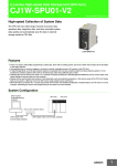
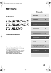
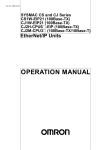
The SPU-Console is connected to the SYSMAC SPU Unit via a LAN. The
SPU-Console dynamically creates windows based on the ID information in the
SYSMAC SPU Unit that is connected, eliminating the need to set the model in
the software.
2
Section 1-2
SPU-Console
SPU-Console
Setting/Monitoring
Software
SPU Unit
CS-series CPU Unit
Hub or other network device
LAN straight cable
(commercially available)
1-2-2
LAN straight cable (commercially available)
Unit Settings
SYSMAC SPU Unit settings are performed by setting the time according to
the SYSMAC SPU Unit’s location (time zone settings), network settings, such
as the name and IP address on the Window network, and FINS network settings.
1-2-3
Data Collection Settings (Data Storage Mode)
The data in the CPU Unit memory to be collected by the SYSMAC SPU Unit
in Data Storage Mode and the collection method to be used must be specified. Data collection is specified using variables. Variables have attributes,
such as addresses and data types. Scale conversion of variables is also possible. The collection method in Data Storage Mode is called the data collection pattern. Two data collection patterns are supported: basic collection for
single data, and data collection for multiple data. For each collection pattern,
the length of the sampling time interval, number of records, name of the file to
be saved, and number of files are specified.
1-2-4
Event Settings (Data Storage Mode)
In Data Storage Mode, the event settings that specify the time for data collection to start are set. Events are either memory events, which occur when specific conditions are satisfied by values in memory, or schedule events, which
occur at specific times or time intervals.
Schedule events occur at set times, such as every minute, every hour, every
day, or every week (e.g., every Monday). The event rules for data collection
execution or other rules for event processing can be defined. Working days
and the end of the month can also be specified for these events.
The combination of these events with the processing that is performed when
the events occur are called event rules. Event rules such as “data is recorded
in a CSV file whenever a certain bit turns ON” or “data is recorded in a CSV
file every day at 8:00” can be set.
A list of the memory events and schedule events can be displayed. The list
displays which events are set and the operations that will be executed when
these events occur.
1-2-5
Recipe Settings (Data Storage Mode)
In Data Storage Mode, a recipe function is supported to enable writing
numeric data (such as production parameters) and text strings to the memory
areas of the CPU Unit. The SPU Unit specifies how the recipe data is to be
written.
3
Section 1-2
SPU-Console
Recipes can be written in either variable format or contiguous area format. In
variable format, data is written to non-contiguous memory areas. The data
type and scaling method can be specified for writing to multiple non-contiguous memory addresses. In contiguous area format, data is written to a contiguous area at one time. The data type cannot be specified, but more data can
be written at high speed than in variable format.
Starting with version 2.1, the SPU-Console includes an expanded recipe function. With the expanded recipe function, you can search for a desired recipe
key and write data to the memory areas of the CPU Unit. With the previous
recipe function (Ver. 2.0), a recipe key set with Support Software remained
constant unless changed, but with the expanded recipe function, it is possible
to register recipe keys in files or as file names.
1-2-6
Sampling Settings (Sampling Mode)
The data in I/O memory of the CPU Unit that is to be sampled by the SYSMAC SPU Unit is set in Sampling Mode. Sampling data is specified using variables. Variables have attributes, such as addresses and data types. Scale
conversion of variables is also possible. The collection pattern in Sampling
Mode is called the sampling pattern. Four sampling patterns (realtime sampling and sampling 1 to 3) are available. For each sampling pattern, the length
of the sampling time interval, number of records, name of the file to be saved,
and the number of files are specified.
1-2-7
Executing SYSMAC SPU Unit Commands
Commands such as those for starting/stopping sampling for the SYSMAC
SPU Unit can be executed from the SPU-Console.
1-2-8
Monitoring SYSMAC SPU Unit Operating Status
The SYSMAC SPU Unit operating status and error information can be displayed on the SPU-Console.
1-2-9
Historical Trend Graphs
Data recorded in CSV files by the SYSMAC SPU Unit can be displayed on
trend graphs.
1-2-10 Realtime Trend Graphs (Sampling Mode)
Sampling data collected by the SYSMAC SPU Unit can be displayed on trend
graphs in realtime.
1-2-11 Report Function
The report function is used to display in Microsoft Office Excel a CSV file that
is collected by the SPU Unit. This is different from simply opening the CSV file
in Microsoft Office Excel. Variable data collected by the SPU Unit can be displayed in any specified cells.
The report function can be used to easily create reports, such as daily reports
from CSV files collected by the SPU Unit. Sample templates, such as daily
manufacturing reports and error logs, are provided to make it easier to create
various kinds of reports.
4
Section 1-3
System Requirements
1-2-12 FTP Transfers
You can send files collected by the SYSMAC SPU Unit to the FTP server or
receive recipe files from the host computer. Up to ten settings can be used to
send data and another ten settings can be used to receive data. Transferring
data using FTP is used with the advanced settings for data collection patterns.
Transferring data using FTP is used with the expanded recipe function.
1-3
System Requirements
The system requirements to use the SPU-Console are described in this section.
1-3-1
SPU-Console Specifications
Item
Model number
System require- Computer hardware
ments
CD-ROM drive
Display
Mouse
Network card
OS
Application platform
Communications platform
Functions
Unit information
Monitor
Operation
Unit setup
Specification
WS02-SPTC1-V2 (SPU-Console Ver. 2.2)
Computer that meets the system requirements for Microsoft Windows
Required for installation.
Super VGA (800 × 600) or better high-resolution video adapter and monitor
Must conform to the models supported by the applicable OS.
A separate Ethernet network card is required for computers that do not have a
LAN port.
Microsoft Windows XP Home Edition / Professional
Microsoft Windows Vista
Microsoft Windows 7 (32-bit/64-bit edition)
Microsoft Windows 8 (32-bit/64-bit edition)
Microsoft.NET Framework Version 1.1
Microsoft.NET Framework Version 2.0
FinsGateway Version 2003
Unit information, Unit setup, variable settings, collection pattern settings, event
settings, recipe settings, trend graphs, and reports
SYSMAC SPU Unit operating status and error information are displayed.
Operations, such as starting sampling
IP network settings
FINS network settings
Setting items to sample (by specifying I/O memory addresses using variables)
Collection pattern settings (period, file designations for saving, etc.)
Recipe settings (recipe file, write destination, key, etc.)
Settings for conditions according to changes in memory (e.g., bits turning ON)
Variable settings
Collection pattern settings
Recipe settings (Data Storage Mode)
Event settings (in Data Memory event
Storage Mode)
settings
Scheduler setSettings for schedules (e.g., specific times, time intervals)
tings
Trend graphs
Historical trends CSV files are read and displayed.
Realtime trends Current sampling data is read and displayed in trend graphics in real time.
(Sampling
Mode)
Note
1. SPU-Console versions lower than version 2.0 cannot connect to SYSMAC
SPU Units with a unit version of 2.0 or higher.
2. SPU-Console version 2.0 or 2.1 can connect to SYSMAC SPU Units with
a unit version of 2.2. However, the Initial Setting Wizard cannot be used for
unit version 2.2 in this case. Use the Initial Setting Wizard that is provided
5
Section 1-3
System Requirements
with CPU-Console version 2.2 or perform the initial settings with the CPU
Bus Unit settings of the CX-Programmer.
3. SPU-Console version 2.2 can connect to SYSMAC SPU Units with a unit
version of 2.0 or 2.1. In this case, the SPU-Console will operate in the version that corresponds to the unit version of the SYSMAC SPU Unit.
1-3-2
Package Contents
The WS02-SPTC1-V2 contains the following software and data.
SPU-Console Execution
Program
The program that performs SYSMAC SPU Unit settings and operations.
Microsoft .NET Framework
Version 1.1 Redistribution
Package
Microsoft .NET Framework Version 1.1 is required to run the SPU-Console.
The Microsoft .NET Framework Version 1.1 Redistribution Package provided
in the package can be used to install Microsoft .NET Framework in the computer.
SYSMAC SPU Unit System
Data
This system data is transferred to the SYSMAC SPU Unit.
FinsGateway Version 2003
This communications middleware is required to run the SPU-Console.
Manual Data
The manual data includes this manual, the SYSMAC SPU Unit Operation
Manual (Cat. No. V236) in PDF (portable document format).
6
SECTION 2
Setting Up, Starting, and Exiting the SPU-Console
This section describes procedures for installing and uninstalling the SPU-Console, SPU-Console starting methods, and the
basic SPU-Console window configuration.
2-1
2-2
2-3
2-4
Installation . . . . . . . . . . . . . . . . . . . . . . . . . . . . . . . . . . . . . . . . . . . . . . . . . . . .
8
2-1-1
Preparations for Installation . . . . . . . . . . . . . . . . . . . . . . . . . . . . . . .
8
2-1-2
Installing Microsoft .NET Framework . . . . . . . . . . . . . . . . . . . . . . .
8
2-1-3
Installing FinsGateway . . . . . . . . . . . . . . . . . . . . . . . . . . . . . . . . . . .
8
2-1-4
Installing SPU-Console . . . . . . . . . . . . . . . . . . . . . . . . . . . . . . . . . . .
9
Uninstalling SPU-Console. . . . . . . . . . . . . . . . . . . . . . . . . . . . . . . . . . . . . . . .
9
2-2-1
Uninstalling SPU-Console . . . . . . . . . . . . . . . . . . . . . . . . . . . . . . . .
9
2-2-2
Uninstalling FinsGateway . . . . . . . . . . . . . . . . . . . . . . . . . . . . . . . . .
9
Starting and Exiting SPU-Console . . . . . . . . . . . . . . . . . . . . . . . . . . . . . . . . .
10
2-3-1
Starting SPU-Console . . . . . . . . . . . . . . . . . . . . . . . . . . . . . . . . . . . .
10
2-3-2
Exiting SPU-Console . . . . . . . . . . . . . . . . . . . . . . . . . . . . . . . . . . . .
11
SPU-Console Window Configuration . . . . . . . . . . . . . . . . . . . . . . . . . . . . . . .
12
2-4-1
Startup Window. . . . . . . . . . . . . . . . . . . . . . . . . . . . . . . . . . . . . . . . .
12
2-4-2
SPU Unit Online Connection Window . . . . . . . . . . . . . . . . . . . . . . .
13
7
Section 2-1
Installation
2-1
2-1-1
Installation
Preparations for Installation
Before installing the SPU-Console, check the requirements given in 1-3 System Requirements to be sure that all requirements have been met.
The following basic steps are required to set up the SPU-Console.
1,2,3...
1. Installing Microsoft .NET Framework
2. Installing FinsGateway
3. Installing SPU-Console
2-1-2
Installing Microsoft .NET Framework
Microsoft .NET Framework Version 1.1 or Version 2.0 is required to run the
SPU-Console.
Confirming whether
.NET Framework Is
Already Installed
Use Control Panel - Add or Remove Programs on your computer to see if
Microsoft .NET Framework Version 1.1 or Version 2.0 is already installed.
Installing Microsoft
.NET Framework
Microsoft .NET Framework Version 1.1 can be installed from the .NET Framework Redistribution Package included in the SPU-Console installation disk.
If Microsoft .NET Framework Version 1.1 or Version 2.0 is listed in the currently installed programs, then it is already installed and does not need to be
installed again.
Installing the Redistribution Package
1,2,3...
1. Start the computer and log in as a user with administrator rights.
2. The installation program will start automatically. If it does not start automatically, execute the following executable file:
<CD-ROM drive>:\SetupLauncher.exe
3. Click Microsoft .NET Framework 1.1.
4. Follow the installation program instructions to proceed.
2-1-3
Installing FinsGateway
FinsGateway Version 2003 is required to run the SPU-Console.
If a version lower than FinsGateway Version 2003 is already installed, uninstall it first.
The computer must be restarted after installing FinsGateway.
1,2,3...
1. Start the computer and log in as a user with administrator rights.
2. The installation program will start automatically. If it does not start automatically, execute the following executable file:
<CD-ROM drive>:\SetupLauncher.exe
3. Click FinsGateway2003.
4. Follow the instructions provided by the installation program.
5. Restart the computer when installation has been completed.
8
Section 2-2
Uninstalling SPU-Console
2-1-4
Installing SPU-Console
Use the following procedure to install the SPU-Console.
1,2,3...
1. Start the computer and log in as a user with administrator rights.
2. Place the SPU-Console installation disk in the CD-ROM drive.
The installation program will start automatically. If it does not start, execute
the following executable file from the SPU-Console installation disk:
<CD-ROM drive>:\SetupLauncher.exe
3. Click Install SPU-Console.
4. Follow the instructions provided by the installation program.
2-2
Uninstalling SPU-Console
Use the following procedure to uninstall the SPU-Console program and thus
delete it from the computer.
2-2-1
Uninstalling SPU-Console
Use the following procedure to uninstall the SPU-Console.
1,2,3...
1. Start the computer and log in as a user with administrator rights.
2. Select Start - Control Panel.
3. Select Add or Remove Programs (Programs - Programs and Features
in Windows Vista/7).
4. Select OMRON SPU-Console Version 2.2 from the list and click the Add
or Remove Button (the Uninstall Button in Windows Vista/7).
5. Select Remove from the Setup Maintenance Program and then click the
Next Button.
Follow the instructions provided by the uninstallation program.
2-2-2
Uninstalling FinsGateway
Do not uninstall FinsGateway if it is being used by an application other than
SPU-Console.
The computer must be restarted after uninstalling FinsGateway.
1,2,3...
1. Start the computer and log in as a user with administrator rights.
2. Select Start - Control Panel.
3. Select Add or Remove Programs (Programs - Programs and Features
in Windows Vista/7).
4. Select OMRON FinsGateway Version 2003 from the list and click the Add
or Remove Button (the Uninstall Button in Windows Vista/7).
5. Select Remove from the Setup Maintenance Program and then click the
Next Button.
Follow the instructions provided by the uninstallation program.
6. Restart the computer.
7. Execute the following executable file from the SPU-Console installation
disk: <CD-ROM drive>:\FgwUtils\FgwRemover2003.exe
Follow the instructions provided by the uninstallation program.
8. Restart the computer.
9
Section 2-3
Starting and Exiting SPU-Console
2-3
2-3-1
Starting and Exiting SPU-Console
Starting SPU-Console
Select Start - All Program - OMRON - SPU Console 2.2 - SPU Console.
The SPU-Console will be started and the following window will be displayed.
Note
(1) The user must have administrator rights to run the SPU-Console. Log in
as a user that has administrator rights.
(2) More than one copy of SPU-Console can be started at the same time.
(3) The SPU-Console can be started from CX-Programmer (version 7.2 or
higher). To do so, right-click a SYSMAC CPU Unit in the PLC I/O Tables
Window and select Start Special Application - Start Only. The SPUConsole will start. (The SPU-Console will not start with settings inherited
even if Start with Settings Inherited is selected.)
Note
If the following message appears when starting the SPU-Console, use the following procedure to reinstall the SPU-Console: “File or assembly name of
FgwDotne, or one of its dependencies, was not found.”
• Start the Setup Maintenance Program using the following procedure in
2-2-1 Uninstalling SPU-Console.
10
Section 2-3
Starting and Exiting SPU-Console
• Select Repair from the Setup Maintenance Program and then click the
Next Button.
Follow the instructions provided by the uninstallation program.
2-3-2
Exiting SPU-Console
Select File - Exit from the SPU-Console menus.
The SPU-Console will be closed.
11
Section 2-4
SPU-Console Window Configuration
2-4
SPU-Console Window Configuration
The SPU-Console Window consists of several distinct areas. This section
describes the various parts that make up the SPU-Console Window.
2-4-1
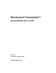
Startup Window
The following window is displayed when the SPU-Console is started. Connected SPU Units and projects are managed in this window.
Menu Bar
Project Explorer
Item
Menu Bar
Project Explorer
12
Function
Provides menus to perform SPU-Console operations. Menu
commands are grouped into related functions. The name of
each group is displayed on the menu bar. The commands
within each group are accessed on pull-down menus.
Manages connected SPU Units and the projects where their
settings are saved.
Section 2-4
SPU-Console Window Configuration
2-4-2
SPU Unit Online Connection Window
The following window is displayed when the SPU Unit is connected online.
Menu Bar
Control Tabs
Control Panel
Status Bar
Item
Menu Bar
Control Tabs
Control Panel
Status Bar
Function
Provides menus to perform SPU-Console operations. Menu commands are grouped into related functions. The name of each group
is displayed on the menu bar. The commands within each group
are accessed on pull-down menus.
The control tabs are used to switch between SPU-Console tab
pages. The name of each tab page is given on the control tab.
When a tab is clicked, the corresponding tab page will be displayed.
The Control Panel is used to start sampling and execute commands to control SPU Unit operation.
The Status Bar displays information, such as the status of the connected SPU Unit.
13
SPU-Console Window Configuration
14
Section 2-4
SECTION 3
Initial Settings of the SYSMAC SPU Unit
This section describes how to make initial settings for SYSMAC SPU Units.
3-1
Outline of Initial Settings . . . . . . . . . . . . . . . . . . . . . . . . . . . . . . . . . . . . . . . .
16
3-2
Making Unit Settings Using the CX-Programmer. . . . . . . . . . . . . . . . . . . . . .
16
3-2-1
Inputting the Settings . . . . . . . . . . . . . . . . . . . . . . . . . . . . . . . . . . . .
16
3-2-2
Enabling the Settings in the SYSMAC SPU Unit . . . . . . . . . . . . . . .
17
3-2-3
Reading Settings from the SYSMAC SPU Unit . . . . . . . . . . . . . . . .
17
3-2-4
Verifying the SYSMAC SPU Unit Settings . . . . . . . . . . . . . . . . . . .
18
3-2-5
Restoring the Default Settings. . . . . . . . . . . . . . . . . . . . . . . . . . . . . .
18
Making Initial Settings Using the Initialization Wizard. . . . . . . . . . . . . . . . . .
18
3-3-1
Connecting the SYSMAC SPU Unit and Computer with a LAN Cable
18
3-3-2
Starting the SYSMAC SPU Unit in Maintenance Mode . . . . . . . . .
19
3-3-3
Setting the IP Address of the Computer . . . . . . . . . . . . . . . . . . . . . .
19
3-3-4
Making the Initial Settings for the SYSMAC SPU Unit. . . . . . . . . .
21
Confirming Connections . . . . . . . . . . . . . . . . . . . . . . . . . . . . . . . . . . . . . . . . .
23
3-3
3-4
15
Section 3-1
Outline of Initial Settings
3-1
Outline of Initial Settings
Initial settings must be performed to use a SYSMAC SPU Unit.
In the initial settings, you set the IP address and other network settings, the
time zone, and other settings. You can use the SYSMAC CS/CJ-series CXProgrammer Support Software or the Initialization Wizard that comes with the
SPU-Console to make the initial settings. Set the initial settings of the SYSMAC SPU Unit using either method.
3-2
Making Unit Settings Using the CX-Programmer
Aside from using the SPU-Console Initialization Wizard, it is also possible to
use the CX-Programmer to make the SYSMAC SPU Unit settings. The procedure is shown below.
Note
3-2-1
In order to use this settings function, CX-Programmer Version 7.2 or later and
a SYSMAC SPU Unit of unit version 2.0 or later are required.
Inputting the Settings
1,2,3...
1. Place the CX-Programmer online and open the PLC I/O Table Window.
2. In the I/O Table Window, select Transfer from PLC from the Option Menu
in the I/O Table Window and transfer the CPU Bus Unit settings from the
PLC.
3. In the PLC I/O Table Window, select the SYSMAC SPU Unit. Right-click
and select Edit CPU Bus Unit Settings. The SYSMAC SPU Unit's Edit
Parameters Dialog Box will be displayed.
4. Input the settings in the Edit Parameters Dialog Box.
The following table shows the meanings of the items to be set.
Item
Unit
Unit Name
16
Setting
This is the name displayed under My Network on the Windows
computer. The default is “SPU-default.” Input a maximum of 64
characters.
Set a unique name for each SYSMAC SPU Unit connected to
the same network.
Unit names of more than 15 characters cannot be found from
Windows Explorer.
Section 3-2
Making Unit Settings Using the CX-Programmer
Item
Work group
Time zone
Setting
Input the work group name for the Windows network.
Set the time zone for the SYSMAC SPU Unit. The factory setting is UTC (Coordinated Universal Time). Be sure to set the
time zone for the region where the Unit is to be used.
Interface
Obtain an IP address Select this setting to automatically obtain an IP address using
automatically
the DHCP (Dynamic Host Configuration Protocol).
Note A DHCP server must exist on the network/system to use
this setting. If you do not know if a DHCP server exists,
ask your system administrator.
IP address
Input the IP address.
Set a unique IP address for each SYSMAC SPU Unit connected to the same network.
Subnet mask
Set the same subnet mask as the one set on the network computer to be connected.
Specify the default
To specify the default gateway, select this option and set the IP
gateway
address for the default gateway.
FINS Network Settings
Network address
Input the FINS network address for the Ethernet communications service that is built into the SYSMAC SPU Unit. The setting must match the FINS network address for the computer's
FinsGateway ETN_UNIT service.
Node address
Input the FINS node address for the Ethernet communications
service that is built into the SYSMAC SPU Unit. It cannot be
input if the automatic generation method is enabled. In that
case, the host portion of the IP address becomes the FINS
node address.
Enable automatic
When this setting is selected, automatic generation is set as
generation.
the FINS-IP address conversion method and the host portion
of the IP address becomes the FINS node address.
UDP port
Set the UDP port to be used.
3-2-2
Enabling the Settings in the SYSMAC SPU Unit
1,2,3...
1. With the CX-Programmer connected online, display the SYSMAC SPU
Unit's Edit Parameters Dialog Box.
2. Click the Transfer to Unit Button.
If the PLC operating mode is MONITOR or RUN mode, change it to PROGRAM mode.
3. A dialog box will be displayed to restart the Unit. Click the Yes Button. The
settings will be enabled after the Unit has been restarted.
Note
3-2-3
Close the Edit Parameters Dialog Box before restarting the SYSMAC SPU
Unit. If the Unit is restarted while the dialog box is open, the connection with
the Unit will be broken. Close the Edit Parameters Dialog Box and then display it again.
Reading Settings from the SYSMAC SPU Unit
1,2,3...
1. With the CX-Programmer connected online, display the SYSMAC SPU
Unit's Edit Parameters Dialog Box.
2. Click the Transfer to Computer Button. The Unit settings will be displayed
in the Edit Parameters Dialog Box.
17
Making Initial Settings Using the Initialization Wizard.
Note
3-2-4
Section 3-3
Be sure to execute command 24 (Enable Unit settings) after making the Unit
settings. If this command is not executed, the actual settings may not be the
same as the settings displayed in the Edit Parameters Dialog Box.
Verifying the SYSMAC SPU Unit Settings
1,2,3...
1. With the CX-Programmer connected online, display the SYSMAC SPU
Unit's Edit Parameters Dialog Box.
2. Click the Compare Button. The verification results will be displayed.
3-2-5
Restoring the Default Settings
1,2,3...
1. Display the SYSMAC SPU Unit's Edit Parameters Dialog Box.
2. Click the Set Defaults Button. The default settings will be entered.
Note
3-3
The CPU Unit and CX-Programmer can be connected online using the FinsGateway message service that is included with the SYSMAC SPU Unit, but do
not connect the CPU Unit online via the SYSMAC SPU Unit when making the
Unit settings. In that case, use a protocol such as the Toolbus protocol to connect the CX-Programmer and the CPU Unit.
Making Initial Settings Using the Initialization Wizard.
Use the following procedures to make the initial settings with the Initialization
Wizard.
Connect the SYSMAC SPU Unit and computer with a LAN cable.
↓
Start the SYSMAC SPU Unit in Maintenance Mode.
↓
Set the IP address of the computer.
↓
Make the initial settings for the SYSMAC SPU Unit with the Initialization
Wizard.
3-3-1
3-3-1
3-3-2
3-3-3
3-3-4
Note
The model number and lot number of the SYSMAC SPU Unit are required to
make the initial settings for the SYSMAC SPU Unit. Before mounting the SYSMAC SPU Unit, record the information on the sticker on the side of the Unit.
The model number and lot number are also printed on the sticker on the package.
Note
If you perform the setup with the SYSMAC SPU Unit’s Initialization Wizard, all
settings (such as the Data Collection Settings and Unit Settings) will be initialized. Confirm that it is OK to initialize all settings before you make the initial
settings.
Connecting the SYSMAC SPU Unit and Computer with a LAN
Cable
The SYSMAC SPU Unit is connected to the computer with a LAN cable. The
connection can be made either through a hub or other network device. (If the
connection cannot be made, refer to Appendix B Troubleshooting Connections.)
Connect the LAN cable to the LAN1 port on the SYSMAC SPU Unit.
18
Section 3-3
Making Initial Settings Using the Initialization Wizard.
SPU-Console
Setting/Monitoring
Software
SPU Unit
CS-series CPU Unit
Hub or other network device
LAN straight cable
(commercially available)
Note
3-3-2
LAN straight cable (commercially available)
Do not connect to the network more than one SYSMAC SPU Unit for which
initial settings have not been made. IP addresses will be duplicated, and communications may not be possible. Disconnect the LAN cable from all SYSMAC
SPU Units except for one and set one SYSMAC SPU Unit at a time.
Starting the SYSMAC SPU Unit in Maintenance Mode
Use the following procedure to start the SYSMAC SPU Unit in Maintenance
Mode.
1,2,3...
1. Connect the LAN cable to the LAN1 port on the SYSMAC SPU Unit.
2. Turn ON pins 4 and 6 on the DIP switch on the SYSMAC SPU Unit and
then turn ON the power supply to the PLC. The SYSMAC SPU Unit will
start in Maintenance Mode.
Pin 4 ON = IP address set to 192.168.0.100.
Pin 6 ON = Start in Maintenance Mode.
When the SYSMAC SPU Unit has started in Maintenance Mode, “NM” will
be displayed on the 7-segment display on the SYSMAC SPU Unit.
N
M
3. Check the IP address of the SYSMAC SPU Unit using the following procedure.
• Press the SELECT Switch to select command 05 and then press the
ENTER Button twice. The IP address will be displayed on the 7-segment display.
• Confirm that 192.168.0.100 is displayed as the IP address.
• If the IP address is not 192.168.0.100, check the DIP switch setting
and repeat the procedure from step 2.
3-3-3
Setting the IP Address of the Computer
To enable connecting to the SYSMAC SPU Unit in Maintenance Mode, the IP
address of the computer must be temporarily set to 192.168.0.200.
The method for setting the IP address depends on the operating system of the
computer. Refer to user documentation provided with your computer for
details.
The following procedure is for Windows XP Professional.
1,2,3...
1. Connect the LAN cable to the LAN port on the computer and turn ON the
power supply to the computer.
19
Making Initial Settings Using the Initialization Wizard.
Section 3-3
2. Log in using the account of the computer administrator.
3. Select Start - Control Panel.
4. Click Network and Internet Connections and then click Network Connections.
If the control panel is set for classic display, click Network Connections
from the Control Panel.
• For Windows 7, click View Network Status and Tasks in the Control
Panel and then click Change adapter settings.
5. Right-click the network to be set and select Properties from the menu, as
shown below.
20
Section 3-3
Making Initial Settings Using the Initialization Wizard.
The Local Area Connection Properties Dialog Box of the network that was
selected will be displayed.
6. Select Internet Protocol (TCP/IP) and then click the Properties Button.
The Internet Protocol (TCP/IP) Properties Dialog Box shown below will be
displayed.
7. Recording the Current IP Address
If Use the following address is set, record the current IP address of the
computer so that it can be set again later.
IP address
Subnet mask
Default gateway
.
.
.
.
.
.
.
.
.
8. Temporarily Changing the IP Address
Select Use the following address and change the IP address to the values given below.
• IP address = 192.168.0.200
• Subnet mask = 255.255.255.0
9. Click the OK Button to change the setting
It may be necessary to restart the computer to make the new settings valid.
This completes setting the IP address of the computer.
3-3-4
Making the Initial Settings for the SYSMAC SPU Unit
1,2,3...
1. Select Start - All Program - OMRON - SPU Console 2.2 - Initialization
Wizard.
The Initialization Wizard will be started.
2. Input the SYSMAC SPU Unit product information.
Input the model number and lot number of the SYSMAC SPU Unit and click
the Next Button.
21
Making Initial Settings Using the Initialization Wizard.
Section 3-3
The model number and lot number can be found on the sticker on the side
of the SYSMAC SPU Unit or on the sticker on the package.
3. Make the Unit settings.
The following items are set.
Item
Unit Name
Time zone
Setting
This is the name displayed under My Networks on the
Windows computer. The default is “SPU-default.” Input a
maximum of 64 characters.
Set a unique name for each SYSMAC SPU Unit connected to the same network.
Unit names of more than 15 characters cannot be found
from Windows Explorer.
Set the time zone of the applicable region.
Set all of the required items and then click the Next Button.
4. Make the network settings.
Set the following items.
Item
Setting
Obtain an IP address Select this setting to automatically obtain an IP address
automatically
using the DHCP (Dynamic Host Configuration Protocol).
Use the following IP
address
IP address
Subnet mask
Network address
Node address
Enable automatic
generation.
Note A DHCP server must exist on the network/system
to use this setting. If you do not know if a DHCP
server exists, ask your system administrator.
Select this setting when not automatically obtaining an IP
address using the DHCP and then set the IP address and
subnet mask.
Input the IP address.
Set a unique IP address for each SYSMAC SPU Unit connected to the same network.
Set the same subnet mask as the one set on the network
computer to be connected.
Input the FINS network address for the Ethernet communications service that is built into the SYSMAC SPU Unit.
The setting must match the FINS network address for the
computer's FinsGateway ETN_UNIT service.
Input the FINS node address for the Ethernet communications service that is built into the SYSMAC SPU Unit.
The node address does not need to be input if the automatic generation method is enabled. In that case, the
host portion of the IP address becomes the FINS node
address.
When this setting is selected, automatic generation is set
as the FINS-IP address conversion method and the host
portion of the IP address becomes the FINS node
address.
Set all of the required items and then click the Next Button.
5. Transferring System Data
Check that the settings are correct and then click the Execute Button.
System data will be transferred to the SYSMAC SPU Unit.
22
Section 3-4
Confirming Connections
6. Exiting the Initialization Wizard
The following window will be displayed if the Wizard is exited normally.
Click the Finish Button to exit.
Note
The Initialization Wizard cannot be connected to the SYSMAC SPU Unit in the
following cases.
• When the computer log-on destination is taken as the domain:
Change the computer log-on destination to the computer rather than the
domain.
• When firewall software is used:
Set the firewall so that the SYSMAC SPU Unit IP address can be used, or
disable the firewall.
3-4
Confirming Connections
After making the initial settings, use the following procedure to confirm that
the SYSMAC SPU Unit on the network can be recognized from the computer.
1,2,3...
1. Return the computer's network settings to their previous values using the
procedure in 3-3-3 Setting the IP Address of the Computer as a guide.
2. Turn OFF the power supply to the PLC and then turn OFF all pins on the
DIP switch on the SYSMAC SPU Unit.
3. Turn ON the power supply to the PLC to start the SYSMAC SPU Unit.
4. Search for SYSMAC SPU Units on the network using the Windows Search
for Computers command.
• For Windows XP, right-click My Network Places on the Start Menu
and then select Search for Computers.
• For Windows 7, select Network from the Explorer and enter the unit
name of the SYSMAC SPU Unit in the Search Box.
23
Section 3-4
Confirming Connections
5. Input the Unit Name or IP address for the Computer name and then click
the Search Button.
The following display will appear if the SYSMAC SPU Unit is found.
• Windows XP
• Windows 7
24
SECTION 4
Changing the SYSMAC SPU Unit’s Operating Mode
This section provides information on the SYSMAC SPU Unit’s operating modes, including procedures for confirming and
changing the operating mode.
4-1
Operation Overview . . . . . . . . . . . . . . . . . . . . . . . . . . . . . . . . . . . . . . . . . . . .
26
4-2
Confirming the Operating Mode . . . . . . . . . . . . . . . . . . . . . . . . . . . . . . . . . . .
26
4-3
Changing the Operating Mode . . . . . . . . . . . . . . . . . . . . . . . . . . . . . . . . . . . .
27
25
Section 4-1
Operation Overview
4-1
Operation Overview
The SYSMAC SPU Unit provides two operating modes: Data Storage Mode
and Sampling Mode. For an overview of operating modes, refer to SECTION 1
Overview of Features and Functions. Either of these operating modes can be
selected.
The Data Storage Mode is the default operating mode for a SYSMAC SPU
Unit with unit version 2.0 or later.
To select an operating mode, stop all SYSMAC SPU Unit operations. The
operating mode cannot be changed while the SYSMAC SPU Unit is operating.
Use the following procedure to change the SYSMAC SPU Unit operating
mode.
1,2,3...
1. Change the DIP switch setting on the SYSMAC SPU Unit and restart using
the restart command.
2. After restarting, execute the command to change the operating mode.
3. When the command to change the operating mode has completed executing, change the DIP switch setting on the SYSMAC SPU Unit and restart
the Unit. The SYSMAC SPU Unit will use the newly set operating mode.
4-2
Confirming the Operating Mode
The following three methods can be used to confirm the operating mode.
Using 7-segment display on Front of the SYSMAC SPU Unit
The operating mode is displayed on the 7-segment display on the front of the
SYSMAC SPU Unit.
7-segment display
Operating mode
Data Storage Mode
Sampling Mode
Using SPU-Console Status Bar
1,2,3...
1. Connect to the SYSMAC SPU Unit using the SPU-Console. For details on
connection methods, refer to 5-1 Connecting and Disconnecting.
2. The operating mode is displayed in the Status Bar at the bottom right of
SPU-Console.
Using SPU-Console: Unit Information - System Information - Mode
1,2,3...
26
1. Connect to the SYSMAC SPU Unit using the SPU-Console. For details on
connection methods, refer to 5-1 Connecting and Disconnecting.
Section 4-3
Changing the Operating Mode
2. Select the Unit Information Tab and System Information to display the
system information.
3. The operating mode is displayed in the Mode Field in the System Information Window.
4-3
Changing the Operating Mode
Use the following procedure to change the operating mode.
1,2,3...
1. First, record the SYSMAC SPU Unit’s currently set DIP switch setting.
2. Turn ON pins 4 and 6 only of the SYSMAC SPU Unit’s DIP switch.
3. Select command 12 (Restart Unit) using the SELECT Switch, and then
press the ENTER Button. For details on command execution methods, refer to 6-3 Executing Commands from the SYSMAC SPU Unit. The Unit will
restart. Check that “NM” is shown on the 7-segment display.
N
M
4. Change the SYSMAC SPU Unit’s operating mode. Select the number of
the operating mode to be changed to using the SELECT Switch, and then
press the ENTER Button.
Operating mode change operation
Changing to Data Storage Mode
Changing to Sampling Mode
Number to select using the
SELECT Switch
53
68
5. The display will change from “M1” in order. Wait until “F” is displayed.
6. When “F” is displayed in the 7-segment display, return the DIP switch to the
status recorded in step 1.
27
Changing the Operating Mode
Section 4-3
7. Select command 12 (Restart Unit) using the SELECT Switch and press
the ENTER Button. The SYSMAC SPU Unit will restart and operate in the
newly set operating mode.
8. Check that the operating mode has changed. Refer to the confirmation
methods in 4-2 Confirming the Operating Mode.
28
SECTION 5
Connecting to an SYSMAC SPU Unit
This section provides information on connecting the SPU-Console to SYSMAC SPU Units, managing SYSMAC SPU Unit
connections, editing settings offline, transferring setting files between the SPU-Console and SYSMAC SPU Units, and
recording files.
5-1
5-2
5-3
5-4
Connecting and Disconnecting . . . . . . . . . . . . . . . . . . . . . . . . . . . . . . . . . . . .
30
5-1-1
Connecting the SYSMAC SPU Unit and Computer with a LAN Cable
30
5-1-2
FINS Network Settings . . . . . . . . . . . . . . . . . . . . . . . . . . . . . . . . . . .
30
5-1-3
Starting the SPU-Console . . . . . . . . . . . . . . . . . . . . . . . . . . . . . . . . .
31
5-1-4
Registering SYSMAC SPU Units . . . . . . . . . . . . . . . . . . . . . . . . . . .
33
5-1-5
Checking the Connections. . . . . . . . . . . . . . . . . . . . . . . . . . . . . . . . .
34
5-1-6
Connecting to a SYSMAC SPU Unit . . . . . . . . . . . . . . . . . . . . . . . .
35
5-1-7
Disconnecting . . . . . . . . . . . . . . . . . . . . . . . . . . . . . . . . . . . . . . . . . .
36
Managing Connection Destinations. . . . . . . . . . . . . . . . . . . . . . . . . . . . . . . . .
36
5-2-1
Changing and Deleting SYSMAC SPU Unit Registrations . . . . . . .
36
5-2-2
Managing SYSMAC SPU Units by Group . . . . . . . . . . . . . . . . . . . .
37
5-2-3
Moving SYSMAC SPU Unit Registrations . . . . . . . . . . . . . . . . . . .
37
5-2-4
Advanced SPU Unit Settings . . . . . . . . . . . . . . . . . . . . . . . . . . . . . .
38
5-2-5
Importing and Exporting Destination SYSMAC SPU Unit Registration
39
5-2-6
Project Save Location . . . . . . . . . . . . . . . . . . . . . . . . . . . . . . . . . . . .
39
Editing Settings Offline (Unconnected) . . . . . . . . . . . . . . . . . . . . . . . . . . . . .
40
5-3-1
Adding or Deleting a Project. . . . . . . . . . . . . . . . . . . . . . . . . . . . . . .
40
5-3-2
Changing or Copying a Project . . . . . . . . . . . . . . . . . . . . . . . . . . . . .
41
5-3-3
Starting Offline Editing . . . . . . . . . . . . . . . . . . . . . . . . . . . . . . . . . . .
42
5-3-4
Saving and Exiting a Project . . . . . . . . . . . . . . . . . . . . . . . . . . . . . . .
42
Saving and Transferring Settings. . . . . . . . . . . . . . . . . . . . . . . . . . . . . . . . . . .
43
5-4-1
5-5
Transferring Settings from the SYSMAC SPU Unit to the
Personal Computer . . . . . . . . . . . . . . . . . . . . . . . . . . . . . . . . . . . . . .
43
5-4-2
Saving Settings to the Computer . . . . . . . . . . . . . . . . . . . . . . . . . . . .
43
5-4-3
Reading Settings from the Computer . . . . . . . . . . . . . . . . . . . . . . . .
43
5-4-4
Transferring Settings from the Personal Computer to the
SYSMAC SPU Unit . . . . . . . . . . . . . . . . . . . . . . . . . . . . . . . . . . . . .
44
5-4-5
Transferring Projects Edited Offline to the SYSMAC SPU Unit . . .
45
Recording Files . . . . . . . . . . . . . . . . . . . . . . . . . . . . . . . . . . . . . . . . . . . . . . . .
45
5-5-1
Location of Record Files . . . . . . . . . . . . . . . . . . . . . . . . . . . . . . . . . .
45
5-5-2
Accessing Record Files on a Windows Network . . . . . . . . . . . . . . .
45
5-5-3
Format of Record Files . . . . . . . . . . . . . . . . . . . . . . . . . . . . . . . . . . .
47
5-5-4
Saving Record Files. . . . . . . . . . . . . . . . . . . . . . . . . . . . . . . . . . . . . .
47
5-5-5
File Copy Options (Data Storage Mode). . . . . . . . . . . . . . . . . . . . . .
49
29
Section 5-1
Connecting and Disconnecting
5-1
Connecting and Disconnecting
This section describes how to connect/disconnect the SPU-Console to/from
SYSMAC SPU Units.
5-1-1
Connecting the SYSMAC SPU Unit and Computer with a LAN
Cable
The SYSMAC SPU Unit is connected to the computer with a LAN cable.
The connection can be made either through a hub or other network device.
Connect the LAN cable to the LAN1 port on the SYSMAC SPU Unit.
SPU-Console
Setting/Monitoring
Software
SPU Unit
CS/CJ-series CPU Unit
Hub or other network device
LAN straight cable
(commercially available)
Note
LAN straight cable (commercially available)
(1) Do not connect to the network more than one SYSMAC SPU Unit for
which initial settings have not been made. IP addresses will be duplicated, and communications may not be possible. Disconnect the LAN cable
from all SYSMAC SPU Units except for one and set one Unit at a time.
Initial settings for the SYSMAC SPU Unit are made using the Initialization
Wizard. Refer to SECTION 3 Initial Settings of the SYSMAC SPU Unit.
(2) Connecting to the SYSMAC SPU Unit is not possible in the following cases.
• When the computer log-on destination is taken as the domain:
Change the computer log-on destination to the computer rather than
the domain.
• When firewall software is used:
Set the firewall so that the SYSMAC SPU Unit IP address can be used,
or disable the firewall.
5-1-2
FINS Network Settings
FinsGateway, OMRON's communications middleware, is included with the
SYSMAC SPU Unit, and the SPU-Console is connected to the SYSMAC SPU
Unit using the FINS message service. If the SPU-Console cannot be connected, set the FINS network addresses for the computer's FinsGateway and
the SYSMAC SPU Unit's Ethernet communications service to the same value.
The FINS network default address for the SYSMAC SPU Unit's Ethernet communications service is 2.
The network address for the SYSMAC SPU Unit can be set in the initial settings. For details, refer to SECTION 3 Initial Settings of the SYSMAC SPU
Unit.
30
Section 5-1
Connecting and Disconnecting
Computer
SPU-Console
FinsGateway
SYSMAC SPU Unit
Ethernet
communications
service
CS/CJ-series
CPU Unit
CS1 bus
communications
service
Same network address
Note
The procedure for checking the FINS network address for the FinsGateway at
the computer is given below.
1,2,3...
1. Start the FinsGateway Setting utility by selecting All Programs - FinsGateway - FinsGateway Setting.
2. On the Basic Tab Page in the FinsGateway Setting Window, check under
Service to confirm that the ETN_UNIT service has started. If the service
has not started, start it by selecting ETN_UNIT and clicking the Start Button in the Service Setting Panel.
3. On the Basic Tab Page in the FinsGateway Setting Window, select Network and Unit to display the Network and Unit Setting Panel The Ethernet
communications service network will be displayed as “local network n
(Ethernet),” with “n” representing the network address. Confirm that it is
identical to the FINS network address (default: 2) for the SYSMAC SPU
Unit's Ethernet communications service. If it is different, click the Properties Button to display the ETN_UNIT Properties Dialog Box. In the Network
Tab Page, input the identical network address. After the new network address has been input, restart the ETN_UNIT to enable the new address.
5-1-3
Starting the SPU-Console
When the SPU-Console is started, the Project Explorer Window is displayed
as shown below. SYSMAC SPU Unit connection destinations can be managed from the SPU-Console. SYSMAC SPU Unit settings are called
“projects,” and they can be edited and managed individually. SYSMAC SPU
Unit connection destinations and projects are managed using the Project
Explorer. The Project Explorer Window configuration is shown below.
31
Section 5-1
Connecting and Disconnecting
SPU Unit List:
Displays a list of
registered connection
destinations.
Project List:
Displays a list of
projects managed
by Unit.
The meanings of the column headings in the Project List are as follows:
Heading
Name
Mode
Description
Date changed
Folder
Version
32
Meaning
Displays the project name.
Displays the operating mode for the project.
Displays a description of the project.
Displays the date on which the project was changed.
Displays the path of the local folder where the project is saved.
Displays the unit version of the SYSMAC SPU Unit.
Connecting and Disconnecting
5-1-4
Section 5-1
Registering SYSMAC SPU Units
1,2,3...
1. Click the New SPU Unit Button. The Connection Settings Dialog Box will
be displayed.
2. In the IP Address field, specify the IP address for the SYSMAC SPU Unit
that is to be connected.
In the Name field, specify a text string to identify the SPU Unit.
33
Connecting and Disconnecting
Section 5-1
3. Click the OK Button to register the new Unit to the SPU Unit List. The newly
registered Unit will be displayed in the SPU Unit List as shown below.
5-1-5
Checking the Connections
To check whether it is possible to connect to a SYSMAC SPU Unit, select the
Unit in the SPU Unit List and then click the Confirm Button.
If it is not possible to connect, an error message will be displayed. Refer to
Appendix B Troubleshooting Connections and apply countermeasures.
34
Connecting and Disconnecting
5-1-6
Section 5-1
Connecting to a SYSMAC SPU Unit
From the SPU Unit List, select the SYSMAC SPU Unit to which to connect
and then click the Connect Button. The following window will be displayed
when the connection is made.
CS-series SYSMAC SPU
Unit
35
Managing Connection Destinations
Section 5-2
CJ-series SYSMAC SPU
Unit
5-1-7
Disconnecting
Select File - Disconnect.
The connection to the SYSMAC SPU Unit will be broken.
5-2
Managing Connection Destinations
This section describes how to manage connections from the SPU-Console to
multiple SYSMAC SPU Units.
5-2-1
Changing and Deleting SYSMAC SPU Unit Registrations
• To change a SYSMAC SPU Unit's registered information, select that SPU
Unit from the Project Explorer's SPU Unit List and click the Edit Button.
• To delete a connected SYSMAC SPU Unit, select that Unit from the
Project Explorer's SPU Unit List and click the Delete Button.
36
Managing Connection Destinations
5-2-2
Section 5-2
Managing SYSMAC SPU Units by Group
As shown in the following window, SYSMAC SPU Units can be managed in
groups.
• To create a group, select the Units from the SPU Unit List and click the
New Group Button.
• To delete a group, select the group to delete from the SYSMAC SPU Unit
list and click the Delete Button. If a group is deleted, all the SYSMAC
SPU Units registered in the group will also be deleted.
• To change a group name, select the group from the SYSMAC SPU Unit
list and click the Edit Button.
5-2-3
Moving SYSMAC SPU Unit Registrations
Registered SYSMAC SPU Units can be individually moved to groups. To
move a Unit to a group, select that Unit in the SPU Unit List, press and hold
the Ctrl Key, and drag and drop it in the destination group.
37
Managing Connection Destinations
5-2-4
Section 5-2
Advanced SPU Unit Settings
The SPU-Console can communicate with SYSMAC SPU Units using the FinsGateway ETN_UNIT service. The FINS address of an SYSMAC SPU Unit is
set in the advanced settings.
To make advanced settings, click the Advanced Button from the Destination
Setting Dialog Box. (Refer to 5-1-4 Registering SYSMAC SPU Units.) Knowledge of FinsGateway and FINS is required to make advanced settings.
Identify the FINS Address
with an IP Address
This method is normally selected.
For it, the rightmost byte of the host ID of the IP address is used as the FINS
node address.
FINS-IP Conversion for the FinsGateway ETN_UNIT service is set to either
Automatic Generation or IP Table + Automatic Generation.
38
Managing Connection Destinations
Use the Following FINS
Address
Section 5-2
This method is used to specify the FINS node address of an SYSMAC SPU
Unit.
Specify the FINS node address in the FINS address Field. FINS-IP Conversion for the FinsGateway ETN_UNIT service is set to either IP Address Table
or IP Table + Automatic Generation.
Register for the Ethernet
IP Address Table
If Register for the Ethernet IP address table is selected, the IP address and
FINS node address will be registered in the FinsGateway IP address table
when connecting to an SYSMAC SPU Unit.
To change FinsGateway settings on the computer, click the FinsGateway
Configuration Button.
5-2-5
Importing and Exporting Destination SYSMAC SPU Unit
Registration
Exporting
Use the following procedure to export the registered contents of the destination SYSMAC SPU Unit to a file.
1,2,3...
1. In the SPU-Console, select Export from the File Menu.
2. In the Export Dialog Box, enter the file name where indicated.
3. Click the Save Button.
Importing
Use the following procedure to import the registered contents for the destination SYSMAC SPU Unit from a file.
1,2,3...
1. In the SPU-Console, select Import from the File Menu.
2. In the Import Dialog Box, find the file to be imported and click on the file.
3. Click the Open Button.
5-2-6
Project Save Location
A project is saved in the following folder configuration.
• Root folder: The root folder where the project is saved
• SPU Unit name: The name of the registered SYSMAC SPU Unit
39
Editing Settings Offline (Unconnected)
Section 5-3
• Project name: The name of the project registered in the SYSMAC SPU
Unit
The root folder can be changed to any location.
1,2,3...
1. Click the Option Button in the Project Explorer Window to display the
Project Option Dialog Box.
2. Click the Browse Button and select the folder from the dialog box.
3. Click the OK Button.
5-3
Editing Settings Offline (Unconnected)
The SPU-Console can be used to edit settings without being connected to the
SYSMAC SPU Unit. This operation is called offline editing. With offline editing, settings can be edited by project. Projects that are set can be saved in the
personal computer and transferred to the SYSMAC SPU Unit when the SYSMAC SPU Unit is connected to the personal computer.
5-3-1
Adding or Deleting a Project
As shown in the following window, projects can be managed for individual
SYSMAC SPU Units.
• To add a project, select the Unit in the SPU Unit List and click the New
Project Button.
40
Editing Settings Offline (Unconnected)
Section 5-3
• To delete a project, select the project in the Project List and click the
Delete Button.
When an SPU Unit is deleted from the SPU Unit List, a dialog box will be
displayed to confirm that the projects for that SPU Unit are to be deleted.
If No is selected in the dialog box, the projects can be managed in the
Unregistered SPU Unit List.
5-3-2
Changing or Copying a Project
• To change a project's name or description, select that project in the
Project List and click the Edit Button.
• To copy a project, select that project in the Project List and click the Copy
Button. The copy of the project will be added to the same SYSMAC SPU
Unit.
• To copy a project to a different SYSMAC SPU Unit, select that project in
the Project List and drag and drop it at the destination Unit.
41
Editing Settings Offline (Unconnected)
5-3-3
Section 5-3
Starting Offline Editing
1,2,3...
1. In the Project List, select the project to be edited and then click the Offline
Edit Button.
Note
There are initial settings projects and sample projects under SPU-Default.
Use them for purposes such as creating new projects.
2. Tabs for the items that can be set offline will be displayed, and Offline will
be displayed in the Title Bar and Status Bar. The tabs that are displayed
depend on the project operating mode.
5-3-4
Saving and Exiting a Project
1,2,3...
42
1. Select Save or Save As from the File Menu to save a project. The edited
project will be saved to the personal computer.
Saving and Transferring Settings
Section 5-4
2. Select Offline Close to end offline editing. The saved settings can be
transferred to the SYSMAC SPU Unit after the SYSMAC SPU Unit is connected using the method described next in 5-4 Saving and Transferring
Settings.
5-4
5-4-1
Saving and Transferring Settings
Transferring Settings from the SYSMAC SPU Unit to the Personal
Computer
The SPU-Console automatically reads Unit settings when the SYSMAC SPU
Unit is connected. Therefore, transferring settings to the personal computer is
not required. Use the following procedure to transfer settings explicitly from
the SYSMAC SPU Unit to the personal computer in cases such as when settings are read again at the Unit after the settings that were originally read are
changed at the SPU-Console and then discarded.
1,2,3...
1. First connect the SPU-Console to the relevant SYSMAC SPU Unit to transfer the current SYSMAC SPU Unit settings to the personal computer.
2. In the SPU-Console, select From Unit from the File Menu.
5-4-2
Saving Settings to the Computer
The settings edited using the SPU-Console or the settings read from the SYSMAC SPU Unit can be saved to the personal computer as a project. The
saved settings can also be used in offline editing.
1,2,3...
1. In the SPU-Console, select Save to PC from the File Menu.
2. In the Save in Computer Dialog Box, enter the name and description of the
settings to be saved.
If Display all projects is selected, all of the projects managed by the Project
Explorer will be displayed.
3. Click the OK Button to save the project.
5-4-3
Reading Settings from the Computer
SYSMAC SPU Unit settings (projects) saved in the personal computer can be
read to the SPU-Console. Projects performed using offline editing can also be
read to the SPU-Console using a similar procedure.
43
Saving and Transferring Settings
1,2,3...
Section 5-4
1. In the SPU-Console, select Load from PC from the File Menu.
2. In the Load from Computer Dialog Box, select the project to be read and
click the OK Button. If Display all projects is selected, all of the projects
managed by the Project Explorer will be displayed. Select this checkbox
when reading projects of other SYSMAC SPU Units.
3. Click the Specify Files... Button in the Load from Computer Dialog Box to
display the Load Settings File Dialog Box and select the settings to be
read.
For example, to use settings that have already been saved as collection
settings without setting the IP address in the current SYSMAC SPU Unit at
the time of saving, deselect Unit Settings.
5-4-4
Transferring Settings from the Personal Computer to the SYSMAC
SPU Unit
Use the following procedure to transfer settings edited on the personal computer to the SYSMAC SPU Unit.
1,2,3...
1. Connect the SPU-Console to the SYSMAC SPU Unit to which the settings
will be transferred.
2. In the SPU-Console, select To Unit from the File Menu.
44
Section 5-5
Recording Files
5-4-5
Transferring Projects Edited Offline to the SYSMAC SPU Unit
Projects edited offline can be transferred to the Unit without needing to execute the Connect command from the File Menu in the SYSMAC SPU Unit.
The SPU-Console will automatically read the current Unit settings when it is
connected to the SYSMAC SPU Unit.
Therefore, projects set using offline editing will be overwritten by the current
SYSMAC SPU Unit settings, so the saved projects must be transferred again
after being read. Use the following procedure to transfer settings being edited
offline to the Unit without performing the connection, read, and transfer operations.
1,2,3...
1. Start the offline editing for the project to be transferred.
2. Select To Unit from the File Menu.
The file transfer will start.
3. To enable the transferred project in the SYSMAC SPU Unit, execute the
SYSMAC SPU Unit's Change the Data Collection Settings (Change the
Sampling Settings) command, the Change the Recipe Settings command,
or the Change the Unit Settings command. For details on executing commands, refer to SECTION 6 Executing Commands.
Note
5-5
5-5-1
The transferred settings will be saved in the SYSMAC SPU Unit, but will not
be enabled until the Change the Sampling Settings (Change the Data Collection Settings) command, the Change the Recipe Settings command, or the
Change the Unit Settings command is executed.
Recording Files
Location of Record Files
The data files resulting from recording are saved in a Memory Card mounted
in the SYSMAC SPU Unit. The record files are placed in a folder called “Journal.” The file names are specified when setting data collection settings (sampling settings).
Note
5-5-2
Do not delete the files inside the Journal folder.
The SYSMAC SPU Unit will not operate correctly without these files.
Accessing Record Files on a Windows Network
The data files saved in a Memory Card mounted in the SYSMAC SPU Unit
can be accessed using a shared folder on a Windows network. The shared
folder on the Memory Card is \pccards\PCCard1. Use the following procedure
to access the record files from the computer.
1,2,3...
1. Search for network SYSMAC SPU Units using the Search for Computers
command.
• For Windows XP, right-click My Network Places on the Start Menu
and then select Search for Computers.
• For Windows 7, select Network from the Explorer and enter the unit
name of the SYSMAC SPU Unit in the Search Box.
45
Section 5-5
Recording Files
2. Input the Unit Name or IP address for the Computer name and then click
the Search Button.
The following display will appear if the SYSMAC SPU Unit is found.
3. Double-click the SYSMAC SPU Unit that was found and open the following
folders in order: PCCards - PCCard1 - Journal.
Note
The following method can also be used to easily access the SYSMAC SPU
Unit shared folder from the computer.
(1) Select View - Display the Unit Folder - Journal Folder in the SPU-Console.
(2) Input the UNC address of the shared folder in the SYSMAC SPU Unit in
the address bar of Explorer. For example, input \\192.168.0.100\.
46
Section 5-5
Recording Files
5-5-3
Format of Record Files
The record files are text files in CSV format, as shown below.
index,clocktime,nano,SampleIndex,Tag-0000,Tag-0001,Tag-0002,Tag-0003
0,2004-06-16 11:16:40.443,0443637440,1, 502,18196,32983,18948,
1,2004-06-16 11:16:40.453,0453636704,2, 548,18196,33024,18948,
2,2004-06-16 11:16:40.463,0463635968,3, 607,18196,33077,18948,
3,2004-06-16 11:16:40.473,0473635232,4, 667,18196,33131,18948,
4,2004-06-16 11:16:40.483,0483634496,5, 727,18196,33185,18948,
5,2004-06-16 11:16:40.493,0493633760,6, 777,18196,33229,18948,
6,2004-06-16 11:16:40.503,0503633024,7, 836,18196,33282,18948,
7,2004-06-16 11:16:40.513,0513632288,8, 900,18196,33339,18948,
8,2004-06-16 11:16:40.523,0523631552,9, 950,18196,33384,18948,
9,2004-06-16 11:16:40.533,0533630816,10, 1006,18196,33434,18948,
A header code is placed on the first line. Data codes are placed on the
remaining lines. The data code is described in the following table.
Field
1st field
Index
2nd field
Time stamp
3rd field
Nanoseconds
4th field
Sampling index
Remaining
fields
Return
Sampling data
Note
5-5-4
Item
Meaning
The index number for the data code.
The index is reset to 0 when sampling (data collection) settings or record files are cleared.
The time at which recording was performed.
YYYY-MM-DD hh:mm:ss.ms
The nanoseconds at which recording was performed.
The value is given in nanoseconds.
An index number started from 1 when recording
is started.
The 5th and later fields contain the sampling
data in order.
A line feed code, CR+LF (0x0D 0x0A), is placed
at the end of the line.
Each sampling file has a maximum size of 2 GB.
Saving Record Files
Saving in One File
index
100
The number of records saved in one file is specified in advance in the sampling (data collection) settings. When enough data codes have been saved to
reach the last line, data codes are saved starting at the first record.
(When there are 100 records)
1
2
:
:
When the last record is reached,
records are recorded again from the first row.
97
98
99
47
Section 5-5
Recording Files
Saving in Multiple Files
When saving data in multiple files, if the data record reaches the last line,
recording will continue from the beginning of the next file. When the last line of
the final file is reached, recording will resume from the beginning of the first
file.
When the last record is reach,
recording goes to the first record in
the next file.
When the last record in the last file
is reach, recording returns to the
first record in the first file.
Note
Even if the last record is not reached, a switch is made to the next file at the
following times.
(1) When collection is stopped
(2) When the SYSMAC SPU Unit is restarted
(3) When the Memory Card is removed
(4) When the file is switched by event processing (switch file)
Note
The settings for record files (e.g., format and saving method) are saved in the
Journal folder in the Memory Card containing the record files. To enable the
saved settings in the Unit, execute 20 (Change the data collection settings
(Change the sampling settings)).
If record file settings on the Memory Card differ from those in the SYSMAC
SPU Unit, sampled data will not be recorded correctly. This can happen, for
example, when a Memory Card created for a different SYSMAC SPU Unit is
used. If this happens, update the record file settings by executing command
20 (Change the data collection settings (Change the sampling settings)).
Saving without Specifying
the Number of Records
When data is saved without specifying the number of records, recording starts
from the first record when collection begins. Data is recorded in one file until
data collection stops. The data collected from starting to stopping collection
can be saved in a single file.
Index
0
Recording starts from the
beginning of the file when
collection is started.
1
2
3
:
48
Records are added to the end
of the file until collection is
stopped.
Section 5-5
Recording Files
Note
(1) When data is saved without specifying the number of records, the size of
the file will continue to increase until collection stops. Make sure that the
capacity of the Memory Card is sufficient when saving using this method.
(2) When data is saved in a single file without specifying the number of
records, the previous data in the file is cleared when collection starts.
When not specifying the number of records, saving in multiple files is recommended.
5-5-5
File Copy Options (Data Storage Mode)
In Data Storage Mode, CSV files saved in the Journal folder can be automatically copied with changed file names. The copied files are saved in a folder
called “data” on a Memory Card mounted in the SYSMAC SPU Unit.
Date, time, and variable values can be included with the file names of the copied files. By specifying information such as lot IDs for variable values, collected data can be managed by file name for each lot. For details on copy
options, refer to 10-5-4 Setting Copy Options.
The “data” folders can be accessed as a shared folder in the Windows network. Copied files can be referenced or deleted from a personal computer.
For details, refer to 5-5-2 Accessing Record Files on a Windows Network.
Journal folder
Data folder
DataWriter 0000.csv
DataWriter-20070101_093025-FP900.csv
DataWriter 0001.csv
DataWriter-20070101_101015-FP901.csv
DataWriter 0002.csv
DataWriter 0003.csv
CSV files for which collecting
is completed are copied with
different file names.
49
Recording Files
50
Section 5-5
SECTION 6
Executing Commands
This section describes how to execute commands for SYSMAC SPU Units.
6-1
Command Types and Execution . . . . . . . . . . . . . . . . . . . . . . . . . . . . . . . . . . .
52
6-2
Executing Commands from the SPU-Console . . . . . . . . . . . . . . . . . . . . . . . .
52
6-3
Executing Commands from the SYSMAC SPU Unit. . . . . . . . . . . . . . . . . . .
52
6-4
Executing Commands from the CPU Unit . . . . . . . . . . . . . . . . . . . . . . . . . . .
53
51
Command Types and Execution
6-1
Section 6-1
Command Types and Execution
The SYSMAC SPU Unit supports various commands. For example, Display
the IP address, Start all samplings, and Restart Unit commands are supported. The following methods can be used to execute commands.
Executing Commands
from the SPU-Console
Execute the commands from the SPU-Console connected to the SYSMAC
SPU Unit.
Executing Commands
from the SYSMAC SPU
Unit
Execute the commands using the SYSMAC SPU Unit’s SELECT Switch and
ENTER Button.
Executing Commands
from the CPU Unit
Execute SYSMAC SPU Unit commands from the I/O memory in the CPU Unit.
The supported commands depend on the operating mode.
For details on supported commands in each operating mode, refer to SECTION 15 Data Storage Mode Commands and SECTION 20 Supported Commands.
6-2
Executing Commands from the SPU-Console
Commands are executed from SPU-Console’s Control Panel. Select the command to execute in the Command Selection Box and then click the Exec Button.
Note
6-3
Commands can also be executed by selecting Command - Execute a Command.
Executing Commands from the SYSMAC SPU Unit
The SELECT Switch and ENTER Button are used to execute commands from
the SYSMAC SPU Unit.
Selecting the Command
with the SELECT Switch
Press the switch up to increase the command code.
Press the switch down to decrease the command code.
The currently selected command code will be displayed on the 7-segment display.
Executing the Command
with the ENTER Button
1,2,3...
Use the ENTER Button to execute the command selected with the SELECT
Switch, as described in the following procedure.
1. Confirm that the command number to be executed is displayed on the 7segment display.
2. Press the ENTER Button once.
The command code will flash on the 7-segment display.
52
Section 6-4
Executing Commands from the CPU Unit
3. Press the ENTER Button again.
“A” will be displayed on the 7-segment display and the command will be
executed.
To cancel executing the command, wait for 10 seconds before pressing the
ENTER Button the second time.
6-4
Executing Commands from the CPU Unit
SYSMAC SPU Unit commands can be executed from the CPU Unit.
By setting SYSMAC SPU Unit commands in the CPU Bus Unit Area of the
CPU Unit, the SYSMAC SPU Unit can be operated from the CPU Unit. This
enables the SYSMAC SPU Unit to be operated from the CPU Unit by means
such as ladder programs.
To set a SYSMAC SPU Unit command, specify the command number in the
Command Area of the CPU Bus Unit Area (in the DM Area). The Command
Area address can be calculated using the following equation:
Command Area address = 30,000 + (100 x unit number of SYSMAC SPU
Unit) + 30
For details on the CPU Bus Unit Area, refer to SECTION 7 CPU Bus Unit
Area.
The commands shown in 15-1 List of Data Storage Mode Commands and 201 Commands can be specified. Specify in hexadecimal the command number
written to the Command Area. For example, write 000C to specify command
12 (Restart Unit).
CS/CJ-series CPU Unit
SYSMAC SPU Unit
MOV
#000A
DM30030
#0001:
Command 01
(Start the Basic
Collection)
↓Write
Command
DM30030 Command
CPU Bus Unit Area
DM30008
Status
Unit #0
CPU Bus Unit Area in DM Area
Beginning word n = 30,000 + (100 x unit number)
Unit #0:
Beginning word = 30,000
This method can be used, for example, to start and stop data collection from
the ladder program in the CPU Unit.
Note
Status Area
Starting with SYSMAC SPU Units with unit version 2.0, the previous Status
Area has been integrated with the words allocated in the CPU Bus Unit Area.
The Status Area has been eliminated for SYSMAC SPU Units with unit version 2.2 or later. To execute commands, use the CPU Bus Unit Area.
53
Executing Commands from the CPU Unit
54
Section 6-4
SECTION 7
CPU Bus Unit Area
This section describes the data provided in the CPU Bus Unit Areas.
7-1
CPU Bus Unit Area. . . . . . . . . . . . . . . . . . . . . . . . . . . . . . . . . . . . . . . . . . . . .
56
7-2
CIO Area . . . . . . . . . . . . . . . . . . . . . . . . . . . . . . . . . . . . . . . . . . . . . . . . . . . . .
56
7-3
DM Area . . . . . . . . . . . . . . . . . . . . . . . . . . . . . . . . . . . . . . . . . . . . . . . . . . . . .
62
55
Section 7-1
CPU Bus Unit Area
7-1
CPU Bus Unit Area
For each SYSMAC SPU Unit, a CPU Bus Unit Area is allocated in CPU Unit
memory. The operating status of the SYSMAC SPU Unit is reflected in the
CPU Bus Unit Area of the CPU Unit. Using the CPU Bus Unit Area makes it
possible for a SYSMAC SPU Unit to be operated from a ladder program in the
CPU Unit.
CS/CJ-series CPU Unit
SYSMAC SPU Unit
MOV
#000A
DM30030
#0001:
Command 01
(Start the Basic
Collection)
↓Write
Command
DM30030
Command
CPU Bus Unit Area
DM30008
Status
Unit #0
CPU Bus Unit Area in DM Area
Beginning word n = 30,000 + (100 x unit number)
Unit #0:
Beginning word = 30,000
For example, SYSMAC SPU Unit commands can be used to specify operations such as starting and stopping data collection.
7-2
CIO Area
For each SYSMAC SPU Unit, a CPU Bus Unit Area is allocated in the CIO
Area in the CPU Unit. Information is stored in offset locations from the beginning word of each area, as shown in the table below. Beginning word n can be
calculated using the following equation:
Beginning word address n = 1,500 + (25 x unit number of SYSMAC SPU Unit)
Offset
Memory area name
Data transfer direction
n System information
SPU Unit to CPU Unit
n+1 Collection status for basic collection and collection SPU Unit to CPU Unit
patterns 1 to 15
n+2 Collection status for collection patterns 16 to 31
n+3 Collection status for collection patterns 32 to 47
n+4 Collection status for collection patterns 48 to 63
n+5 Collection status for collection pattern 64
n+6 Collection start specification for basic collection
CPU Unit to SPU Unit
and collection patterns 1 to 15
n+7 Collection start specification for collection patterns
16 to 31
n+8 Collection start specification for collection patterns
32 to 47
n+9 Collection start specification for collection patterns
48 to 63
n+10 Collection start specification for collection pattern
64
56
Section 7-2
CIO Area
Offset
Memory area name
n+11 Collection stop specification for basic collection
and collection patterns 1 to 15
n+12 Collection stop specification for collection patterns
16 to 31
n+13 Collection stop specification for collection patterns
32 to 47
n+14 Collection stop specification for collection patterns
48 to 63
n+15 Collection stop specification for collection pattern
64
n+16 Collection request
n+17 File Copy Flags 1/2
n+18 File Copy Flags 3/4
n+19 File Copy Flags 5/6
n+20 File Copy Flags 7/8
n+21 File Copy Flags 9/10
n+22 Recipe Command Area
n+23 Recipe Status Area
n+24 (Not used.)
Note
System Information
(SPU Unit to CPU
Unit)
Data transfer direction
CPU Unit to SPU Unit
CPU Unit to SPU Unit
SPU Unit to CPU Unit
CPU Unit to SPU Unit
SPU Unit to CPU Unit
---
Do not used the areas indicated “not used.”
SYSMAC SPU Unit status is reflected in memory as follows:
n
15
14
-
-
13
12
11
10
9
8
7
6
5
-
-
-
4
3
2
1
0
RUN
DIP switch pins SW1 to SW6
ERC
Power interruption signal
Memory Card
Bit
0
1
2
3
4
5 to 7
8
9
10
11
12
13
14, 15
Name
RUN
ERC
(Not used.)
Power interruption signal
Memory
Card
(Not used.)
DIP-SW1
DIP-SW2
DIP-SW3
DIP-SW4
DIP-SW5
DIP-SW6
(Not used.)
Description
ON when Unit is operating normally.
ON when a Controller error occurs.
--ON when the power interruption signal turns ON.
ON when a Memory Card is mounted.
--ON when DIP switch pin SW1 is ON.
ON when DIP switch pin SW2 is ON.
ON when DIP switch pin SW3 is ON.
ON when DIP switch pin SW4 is ON.
ON when DIP switch pin SW5 is ON.
ON when DIP switch pin SW6 is ON.
---
57
Section 7-2
CIO Area
Collection Status
(SPU Unit to CPU
Unit)
The operating status of basic collections and collection patterns is reflected in
the corresponding bits.
Bit
Operating status
Collecting
Idling
ON
OFF
The following table shows the bit positions corresponding to the collection patterns.
Data Storage Mode
n+1
15
14
13
12
11
10
9
8
7
6
5
4
3
2
1
15
14
13
12
11
10
9
8
7
6
5
4
3
2
1
Collection patterns 1 to 15
0
Basic collection
n+2
31
30
29
28
27
26
25
24
23
22
21
20
19
18
17
16
n+3
47
46
45
44
43
42
41
40
39
38
37
36
35
34
33
32
n+4
63
62
61
60
59
58
57
56
55
54
53
52
51
50
49
48
n+5
-
-
-
-
-
-
-
-
-
-
-
-
-
-
-
64
Collection patterns 16 to 64
Sampling Mode
n+1
15
14
13
12
11
10
9
8
7
6
5
-
-
-
-
-
-
-
-
-
-
-
4
3
2
1
0
3
2
1
0
Sampling patterns 1 to 3
Realtime
sampling
Collection Start Specification, Collection Stop Specification, Collection Request (CPU
Unit to SPU Unit)
Starts or stops the specified basic collection or collection pattern. Can be
used in Data Storage Mode.
Collection Start
Specification
The SYSMAC SPU Unit begins collecting data when the bit for a collection
request turns ON after the bit for the collection pattern for starting collection
has turned ON. After the SYSMAC SPU Unit has begun collecting data, the
respective collection pattern bits turn OFF. The following table shows the bit
arrangement for basic collection and the collection patterns.
n+6
15
14
13
12
11
10
9
8
7
6
5
4
3
2
1
15
14
13
12
11
10
9
8
7
6
5
4
3
2
1
Collection patterns 1 to 15
Basic collection
n+7
31
30
29
28
27
26
25
24
23
22
21
20
19
18
17
16
n+8
47
46
45
44
43
42
41
40
39
38
37
36
35
34
33
32
n+9
63
62
61
60
59
58
57
56
55
54
53
52
51
50
49
48
n+10
-
-
-
-
-
-
-
-
-
-
-
-
-
-
-
64
Collection patterns 16 to 64
58
0
Section 7-2
CIO Area
Collection Stop
Specification
The SYSMAC SPU Unit stops collecting data when the bit for a collection
request turns ON after the bit for the collection pattern for stopping collection
has turned ON. After the SYSMAC SPU Unit has stopped collecting data, the
respective collection pattern bits turn OFF. The following table shows the bit
arrangement for basic collection and the collection patterns.
n+11
15
14
13
12
11
10
9
8
7
6
5
4
3
2
1
15
14
13
12
11
10
9
8
7
6
5
4
3
2
1
Collection patterns 1 to 15
0
Basic collection
n+12
31
30
29
28
27
26
25
24
23
22
21
20
19
18
17
16
n+13
47
46
45
44
43
42
41
40
39
38
37
36
35
34
33
32
n+14
63
62
61
60
59
58
57
56
55
54
53
52
51
50
49
48
n+15
-
-
-
-
-
-
-
-
-
-
-
-
-
-
-
64
Collection patterns 16 to 64
Collection Request
n+16
15
14
13
12
11
10
9
-
-
-
-
-
-
-
8
-
7
6
5
4
3
-
-
-
-
-
2
-
1
0
Request bit
Bit
0
Note
File Copy Flags (SPU
Unit to CPU Unit)
Name
Request bit
Description
The following collection actions are requested when
this bit turns ON.
• Start the collection pattern that is turned ON by the
collection start specification.
• Stop the collection pattern that is turned ON by the
collection stop specification.
After data collection has started or stopped, the SYSMAC SPU Unit turns OFF the respective collection
specification bit. If both the start and stop bits turn ON
for a collection pattern neither specification will be
executed.
In Sampling Mode, collecting can be started or stopped by executing the command from the CPU Bus Unit Area DM Area (command area (n+30)).
If the copy option is enabled, the status of copy processing is shown by the
File Copy Flags. The File Copy Flags are allocated in words n+17 to n+21 in
the CPU Bus Unit Area in the CIO Area. One byte is allocated for each collection pattern for which the copy option is enabled. The File Copy Flags are allocated in ascending order of the collection pattern numbers. The words where
the File Copy Flags are allocated and the bit configuration are shown below.
59
Section 7-2
CIO Area
15
Offset
8
7
0
n+17
File Copy Flags 2
File Copy Flags 1
n+18
File Copy Flags 4
File Copy Flags 3
n+19
File Copy Flags 6
File Copy Flags 5
n+20
File Copy Flags 8
File Copy Flags 7
n+21
File Copy Flags 10
File Copy Flags 9
7
6
5
4
3
2
1
0
Copy Completed Flag
Copy Error Flag
Copy Cancel Flag
Copy Overflow Flag
Copying Flag
Bit
Note
0
Name
Copy Completed Flag
1
2
Copy Error Flag
Copy Cancel Flag
3
Copy Overflow Flag
4
Copy Overwrite Flag
5 to 6
7
(Not used.)
Copying Flag
Copy Overwrite Flag
Description
Turns ON when copy processing is completed normally.
Turns ON when an error occurs in copy processing.
Turns ON when the CSV file in the copy source
journal folder is overwritten during copy processing.
Turns ON when file copying cannot be performed
because the number of files in the data folder
exceeded the limit during copy processing.
Note: This occurs only when overwriting files in the
data folder is disabled in the copy options.
Turns ON when a file is overwritten (i.e., deleted)
because the number of files in the data folder
exceeded the limit during copy processing. In this
case, the file is copied, so the Copy Completed
Flag will turn ON at the same time.
Note: This occurs only when overwriting files in the
data folder is enabled in the copy options.
--Turns ON when copying is processed. All other bits
will turn OFF. Turns OFF when copy processing is
completed normally or when copy processing ends
due to an error.
(1) The File Copy Flag numbers are allocated in ascending order of the collection pattern numbers for which the copy option is enabled.
(2) If the order of the pattern numbers changes because you change a pattern number, the File Copy Flag numbers will also change.
(3) With SPU-Console version 2.2 or higher, you can check the File Copy
Flag numbers on the list that is displayed when you select all data collection patterns.
60
Section 7-2
CIO Area
Note
All of the File Copy Flags are turned OFF at the following times.
(1) When the SPU Unit is started
(2) When command 04 (clear the collection data) or command 31 (format the
Memory Card) is executed
(3) When data collection settings are changed
Note
If copy processing requires little time because the size of the copied files is
small and if the cycle time of the CPU Unit is long, the File Copy Flags may
not change. As a guideline, we recommend a CPU Unit cycle time of 50 ms or
less for a file size of 1 KB or less. Use caution when you monitor the File Copy
Flags from the program.
Recipe Command Area (CPU Unit to SPU Unit)
Writes recipes. For details on the recipe function, refer to 12-1 Recipe Function.
n+22
15
14
13
12
11
10
9
8
7
6
5
4
3
2
-
-
-
-
-
-
-
-
-
-
-
-
-
-
1
0
Recipe write request bit
Recipe write enabled bit
Bit
0
Note
Name
Recipe write
request bit
1
Recipe write
enabled bit
2 to 15
(Not used.)
Description
When this bit turns ON, the SYSMAC SPU Unit writes
the recipe. After the recipe write operation has been
completed, the operation for turning the bit OFF
depends on the recipe environment settings (handshaking).
• When turned OFF by the SYSMAC SPU Unit, there
is a 1-bit handshake.
• When turned OFF by the CPU Unit, there is a 2-bit
handshake.
For details on recipe environment settings (handshaking), refer to 12-4 Setting the Recipe Environment.
When this flag is OFF, recipes cannot be written.
Keep this bit OFF when equipment is being operated
and when recipes are not to be written.
---
If the expanded recipe function is used, do not turn ON bit 00 from the CPU
Unit. When you use recipes set using the expanded recipe function, turn ON
the bit in the area set for the Recipe Request Bits in the recipe reception settings. Manipulate bit 00 to use recipes set using the version-2 recipe function.
61
Section 7-3
DM Area
Recipe Status Area (SPU Unit to CPU Unit)
The recipe write status is reflected in this area as shown below. Refer to 12-11
Executing Recipes for details on writing recipes.
n+23
15
14
13
12
11
10
9
8
7
6
5
4
3
-
-
-
-
-
-
-
-
-
-
-
-
-
2
1
0
Writing recipe bit
Recipe write complete bit
Recipe write error bit
Bit
0
1
2
3 to 15
7-3
Name
Writing recipe
bit
Recipe write
complete bit
Recipe write
error bit
(Not used.)
Description
ON while a recipe is being written.
ON when the recipe writing operation is completed.
ON when a recipe writing error occurs.
---
DM Area
For each SYSMAC SPU Unit, a CPU Bus Unit Area is allocated in the DM
Area in the CPU Unit. Information is stored in offset locations from the beginning word of each memory area, as shown in the table below. Beginning word
n can be calculated using the following equation:
Beginning word address n = 30,000 + (100 x unit number of SYSMAC SPU
Unit)
62
Section 7-3
DM Area
Offset
15
8
7
0
IP address 1 (www. xxx. yyy. zzz )
n
n+1
www
xxx
yyy
zzz
IP address 2 (www. xxx. yyy. zzz )
n+2
www
xxx
n+3
yyy
zzz
n+4
UDP port
n+5
n+6
FINS address (ETN)
Node address
FINS address (ETN)
Network address
Status
information (SPU
Unit to CPU Unit)
FINS address
(CS1 bus)
Node address
FINS address
(CS1 bus)
Network address
n+7
CPU Unit node address in CS1 bus
n+8
System status
n+9
(Not used.)
n+10
Memory Card capacity (MB)
n+11
Memory Card available space (MB)
n+12
Status of services (FTP transfers and expanded recipe function)
n+13
(Not used.)
... n+19
(Not used.)
n+20
Program number
n+21
Error level
n+22
Error code
n+23
Error subcode
n+24
(Not used.)
... n+29
(Not used.)
Command Area
n+30
n+31
(Not used.)
... n+34
(Not used.)
n+35
Record Counter for Basic Collection
n+35
Record Counter for Collection Pattern 1
n+35
Record Counter for Collection Pattern 2
...
---
Error information
(SPU Unit to
CPU Unit)
Command
execution (CPU
Unit to SPU Unit)
Record Counters
(SPU Unit to CPU
Unit)
Record Counter for Collection Pattern 64
... n+99
Note
Do not used the areas indicated “not used.”
63
Section 7-3
DM Area
System Status (n+8)
The operating status of the SYSMAC SPU Unit is reflected here. The following
table shows the values and their meanings (SYSMAC SPU Unit status).
Value
Status
0
1
Idle
Settings
change
Sampling
Initialization
Archive
2
3
4
Meaning
The SYSMAC SPU Unit is in idle status.
Data collection settings or Unit settings are being
changed.
Data is being collected.
The SYSMAC SPU Unit is being initialized.
Collected data is being saved or data collection settings are being recovered.
Status of Services (FTP Transfers and Expanded Recipe Function) (n+12)
The following bits show the operating status of sending and receiving using
FTP and the operating status of the expanded recipe function.
The following table describes the bits.
n+12
15
14
13
12
11
-
-
-
-
-
Bit
0
1
2
3
4
5
6
7
8
9
10
11
12 to 15
64
Status
Standby
10
9
8
Name
FTP send status (used for
settings 0 to 9)
7
-
6
5
4
3
2
1
0
-
Description
Executable status.
ON when settings 0 to 9 are all on standby.
Changing
The settings are being changed.
ON when the data collection settings or the
FTP settings are being changed.
Executing
Data is being sent using FTP.
ON when any setting from 0 to 9 is being
executed.
(Not used.)
--Standby
Expanded rec- Executable status.
ipe status (used ON when settings 0 to 9 are all on standby.
for settings 0 to
Changing
The settings are being changed.
9)
ON when the recipe settings are being
changed.
Executing
Expanded recipe function is being processed.
ON when any setting from 0 to 9 is being
executed.
(Not used.)
--Standby
FTP receive
Executable status.
status (used for ON when settings 0 to 9 are all on standby.
settings 0 to 9)
Changing
The settings are being changed.
ON when the recipe settings or the FTP
settings are being changed.
Executing
Expanded recipe function is being processed.
ON when any setting from 0 to 9 is being
executed.
(Not used.)
--(Not used.) (Not used.)
---
Section 7-3
DM Area
Error Information
(n+20 to n+23)
Information on the most recent errors to occur in the SYSMAC SPU Unit is
reflected here. These values are not cleared even when the errors are
cleared. The values are cleared when the Unit is restarted or when command
11 (Forced Clear of Error) is executed. For a list of error codes, refer to
Appendix A Troubleshooting with Error Codes.
Command Area
(n+30)
A command can be executed by specifying the command number (in hexadecimal) in this area. It is not possible, however, to continuously execute the
same command in this way. To repeat a command, specify “0” (no command)
and then again specify the command.
The commands that can be executed depend on the operation mode. For
details on commands, refer to 15-1 List of Data Storage Mode Commands
and 20-1 Commands.
Record Counters
(n+35 to n+99)
A record counter is incremented each time a record is added to a CSV file. An
area of 65 words from n+35 to n+99 in the CPU Bus Unit Area in the DM Area
is allocated to the record counters for basic collection and for Data Collection
Mode (64 patterns). The record counters contain 2-byte unsigned integers (0
to 65,535). A record counter is incremented each time a record is added to a
CSV file. If the value exceeds the maximum value of 65,535, it returns to 0.
Note
(1) The offset positions of the record counters are in order of the collection
pattern numbers. This is different from the order in which they are displayed on the SPU-Console.
(2) With SPU-Console version 2.2 or higher, you can change the collection
pattern number of each collection pattern. Refer to 10-5-2 Setting Collection Options for details.
(3) The record counter values return to 0 at the following times.
(a) When the SPU Unit is started
(b) When cyclic collection for the collection pattern is stopped
(c) When the CSV file in which records are recorded for the collection
pattern changes to the next CSV file
(d) When data collection settings are changed
Note
(1) If the number of records recorded in a file is set to 1 in the data collection
pattern settings, the next file is changed to each time a record is recorded. Therefore, the value in the record counter will change between 0 and
1.
(2) If the collection cycle is short or the cycle time of the CPU Unit is long,
changes in the value of the record counter may not be synchronously updated in the CPU Bus Unit Area.
Examples:
• If the collection cycle is 10 ms, the record counter may change as follows: 0, 5, 11, 16, 23, etc.
• If the number of records recorded in a file is set to 1, the record counter
may remain at 0.
Use caution when you monitor the record counters from the program.
65
DM Area
66
Section 7-3
Data Storage Mode
This part of the manual describes using the SPU-Console with the SYSMAC SPU Unit in Data
Storage Mode. Refer to 4-2 Confirming the Operating Mode to confirm that the SYSMAC SPU Unit
is in Data Storage Mode. Refer to 4-3 Changing the Operating Mode to change the SYSMAC SPU
Unit to Data Storage Mode.
SECTION 8
Data Storage Mode
This section introduces the SYSMAC SPU Unit's Data Storage Mode.
8-1
Data Storage Mode Introduction. . . . . . . . . . . . . . . . . . . . . . . . . . . . . . . . . . .
70
69
Data Storage Mode Introduction
8-1
Section 8-1
Data Storage Mode Introduction
Data Storage Mode is used to record specific portions of PLC I/O memory
when a specified event occurs. For example, this mode can be used to record
data when a certain bit turns ON or at a certain time. After an event occurs,
data recording can be continued for a specified time interval. Compared with
Sampling Mode, however, the time interval is less accurate.
The Data Storage Mode settings set the data in the CPU Unit’s I/O memory to
be collected by the SYSMAC SPU Unit and the collection method to be used.
The data to be collected is specified in units called variables. The PLC’s I/O
memory addresses and data types are specified in the variables. Data is converted to the specified data type values and recorded. Scale conversion of
these values is also possible. In Data Storage Mode, collected CSV files can
be copied automatically to separate folders. Date, time, and variable values
can be included with the file names of the copied files. Specifying information
such as this for variable values enables files to be managed.
Data collection patterns consist of basic collection for single data, and data
collection for multiple data (64 max.). For each data collection pattern, the
length of the data collection time interval, number of records, name of the file
to be saved, and whether a single file or multiple files are to be used (saving
format) are specified.
The event settings that specify the time for data collection to start are also set.
Events are either memory events, which occur when specific conditions are
satisfied by values in memory, and schedule events, which occur at specific
times or time intervals. The combination of these events with the processing
that is performed when the events occur are called event rules. Event rules
such as “data is recorded in a CSV file whenever a certain bit turns ON” or
“data is recorded in a CSV file every data at 8:00” can be set.
Of the available data collection patterns, only basic collection will read PLC
I/O memory data in the CPU Unit. Basic collection reads to the SYSMAC SPU
Unit variable data recorded in all data collection patterns for a specific cycle.
This processing is always executed even with basic collection stopped, so
there is no need to start basic collection.
Other data collection patterns use data read to the SYSMAC SPU Unit and
record that data according to the settings. Basic collection enables a time
interval to be set of between several milliseconds to several ten’s of milliseconds, whereas the time interval for other data collection patterns is normally
100 milliseconds or longer.
In addition, Data Storage Mode has a recipe function for writing numeric and
text data, such as production parameters, to a memory area in the CPU Unit.
Using recipes simplifies tasks such as retooling. Numeric and text data can be
created in advance in a CSV file and stored in the SYSMAC SPU Unit. This
data can be changed even while the SYSMAC SPU Unit is operating. With the
recipe function in version 2.0, it is possible to change numeric and text data
while the SYSMAC SPU Unit is in operation. With the expanded recipe function in version 2.1, the data collection settings must be changed to register the
Recipe Request Bit to a variable.
The status of a machine at a certain point in time can be reproduced by using
collected data and the recipe function. For example, the machine's master
data and inspection data are collected as recipe data. The machine's status
can be reproduced by using a recipe to write the collected data to a PLC
memory area. In this way, collected data can be handled not only as a daily
report, but also as parameters for feedback to the machine.
70
Section 8-2
Data Collection Timing
Note
8-2
If you set up the expanded recipe function, the Recipe Request Bits are automatically registered to variables and to memory events. This requires that you
change the data collection settings.
Data Collection Timing
Basic Collection
Cycle
In Data Collection Mode, the SYSMAC SPU Unit loads all of the registered
variable data from the CPU Unit on the cycle that is set for basic collection.
However, the actual cycle on which the SYSMAC SPU Unit loads data is
never shorter than the cycle time of the CPU Unit. The data collection cycle
will always be at least as long as the cycle time even if the cycle that is specified for basic collection is shorter than the cycle time of the CPU Unit.
Note
Cycles for Data
Collection Patterns
Processing to transfer variable data from the CPU Unit to the SYSMAC SPU
Unit on the basic collection cycle is always performed, even when basic collection is stopped (i.e., when writing to CSV files is stopped). It is not necessary to start basic collection.
Data collection patterns use the data that is transferred to the SYSMAC SPU
Unit for basic collection to record the data according to the settings for individual patterns. Therefore, the cycle for a data collection pattern must be at least
as long as the basic collection cycle.
CPU Unit
Basic collection
Collection
pattern
Basic
collection
cycle
Cycle for
collection
pattern
71
Section 8-2
Data Collection Timing
Note
If you set the cycle for a data collection pattern that is shorter than the basic
collection cycle, records will not be recorded for the data collection pattern
until basic collection has been performed.Therefore, we recommend that you
set the cycle for a data collection pattern at least as long as the basic collection cycle.
CPU Unit
Basic
collection
cycle
Timing of Judging
Memory Events
Basic collection
Collection
pattern
Cycle for
collection
pattern
The SYSMAC SPU Unit judges the conditions for memory events. The SYSMAC SPU Unit judges memory events as soon as it loads the data from the
CPU Unit of the PLC for basic collection. Therefore, the values for memory
event conditions must be held for longer than the basic collection cycle.
The following example is for when the memory event condition is When the bit
is ON.
72
Section 8-2
Data Collection Timing
1) Correctly Judging the Condition
Value of memory
event condition
Collection timing
OFF
ON
ON
OFF
OFF
Condition is met because
value has changed from
OFF to ON.
2) Undetected Conditions
Value of memory
event condition
Collection timing
OFF
O
FF
ON
OFF
OFF
Condition is not met
because value has
remained OFF.
Value of memory
event condition
Collection timing
ON
ON
ON
ON
OFF
Condition is not met because
value has remained ON.
Note
The data collection cycle will always be at least as long as the cycle time even
if the basic collection cycle is shorter than the cycle time of the CPU Unit. To
ensure that memory event conditions are correctly judged, we recommend
that the settings satisfy the following guideline.
Time to hold value of memory event condition > Basic collection cycle × 2 +
Cycle time
73
Data Collection Timing
74
Section 8-2
SECTION 9
Monitoring SYSMAC SPU Unit Operating Status
This section describes how to monitor SYSMAC SPU Unit operating status and error status.
9-1
Displaying System Information . . . . . . . . . . . . . . . . . . . . . . . . . . . . . . . . . . .
76
9-2
Displaying Data Collection Status . . . . . . . . . . . . . . . . . . . . . . . . . . . . . . . . .
77
9-2-1
Starting a Collection Pattern. . . . . . . . . . . . . . . . . . . . . . . . . . . . . . .
77
9-2-2
Stopping a Collection Pattern . . . . . . . . . . . . . . . . . . . . . . . . . . . . . .
77
Displaying Error Information . . . . . . . . . . . . . . . . . . . . . . . . . . . . . . . . . . . . .
78
9-3
75
Section 9-1
Displaying System Information
9-1
Displaying System Information
The operating status of an SYSMAC SPU Unit can be monitored from the
System Information display on the Unit Information Tab Page.
System Information Display Items
Item
Current Status
PF-IN Signal
Card
Time
LED
Data collection status
Error list
Product Information
Current Status
Current errors
The SYSMAC SPU Unit model number and system program
version
The SYSMAC SPU Unit current status contains the following status.
Status
Idle
Collecting
Change the settings
Archive
Initialization
76
Content
Operating status of the current SYSMAC SPU Unit
Status of the power failure signal
Whether a Memory card is inserted in the SYSMAC SPU Unit
Memory Card capacity and available space
The time in the SYSMAC SPU Unit
The status of the RUN, ERC, and ERH indicators
Collection pattern currently in use
Meaning
SYSMAC SPU Unit is in idle status.
Basic collection or a collection pattern is being executed.
Data collection settings or Unit settings are being changed.
Record data is being saved or data collection settings are
being recovered.
The SYSMAC SPU Unit is being initialized.
Section 9-2
Displaying Data Collection Status
9-2
Displaying Data Collection Status
The status of data collection can be monitored in the Data Collection Status
Window, from the Unit Information Tab Page. Collection patterns can also be
started and stopped.
The following table shows the meanings of the column headers.
Column header
Status
Name
Description
Interval
Period
Total size
File name
9-2-1
Contents
Collection pattern operating status
Name of collection pattern
Description of collection pattern
Interval for collecting data
Time required to record data in all files
Total size the data collection files and the files to copy to the
data folder
Name of file in which the results of the collection pattern are
saved
Starting a Collection Pattern
1,2,3...
1. Select the collection pattern to be started.
2. Click the Start Button.
9-2-2
Stopping a Collection Pattern
1,2,3...
1. Select the collection pattern to be stopped.
2. Click the Stop Button.
77
Section 9-3
Displaying Error Information
9-3
Displaying Error Information
The error status of an SYSMAC SPU Unit can be monitored from the Error
Information Window on the Unit Information Tab Page.
Refer to Appendix A Troubleshooting with Error Codes for details on error
codes.
Displaying Current Errors
1,2,3...
1. Select the Show Current Errors Option. The current errors in the SYSMAC SPU Unit will be displayed.
• To forcibly clear the current errors, click the Clear Errors Button.
• To save information on the current errors to a file, click the Save to File
Button.
Note
Error information is deleted in the following cases.
(1) When the SYSMAC SPU Unit is restarted
(2) When errors are eliminated
(3) When data collection settings or unit settings are made
(4) When command 11 (Forced Clear of Error) is executed
(5) When the Clear Errors Button is clicked from Error Information in the Unit
Information Tab Page of the SPU-Console.
Displaying Error History
1,2,3...
1. Select the Show error history Option. The error history at the SYSMAC
SPU Unit will be displayed.
• To update to the most recent information, click the Refresh Button.
• To clear the error history, click the Clear Errors Button.
• To save the error history information to a file, click the Save to File Button.
78
Section 9-3
Displaying Error Information
Note
The error history holds a maximum of 80 records. If this number is exceeded,
the oldest item in the history is deleted.The error history is saved to the Memory Card. It is deleted in the following cases:
(1) When the Clear Errors Button is clicked.
(2) When the Memory Card is formatted.
(3) When the Memory Card is replaced.
79
Displaying Error Information
80
Section 9-3
SECTION 10
Data Collection Settings for Data Storage Mode
This section explains how to make the data collection settings for Data Storage Mode operation.
10-1 Data Collection Setting Procedure . . . . . . . . . . . . . . . . . . . . . . . . . . . . . . . . .
82
10-2 Data Collection Settings Window and Operation . . . . . . . . . . . . . . . . . . . . . .
10-2-1 Window Configuration . . . . . . . . . . . . . . . . . . . . . . . . . . . . . . . . . . .
10-2-2 Operations in the Classification Panel . . . . . . . . . . . . . . . . . . . . . . .
10-2-3 Basic Operations in the Variable Panel. . . . . . . . . . . . . . . . . . . . . . .
82
82
83
83
10-3 Setting Variables . . . . . . . . . . . . . . . . . . . . . . . . . . . . . . . . . . . . . . . . . . . . . . .
10-3-1 Adding Variables . . . . . . . . . . . . . . . . . . . . . . . . . . . . . . . . . . . . . . .
10-3-2 Operations in the Variable Properties Dialog Box . . . . . . . . . . . . . .
10-3-3 Setting the Scaling Function for a Variable . . . . . . . . . . . . . . . . . . .
10-3-4 Adding Multiple Variables Together. . . . . . . . . . . . . . . . . . . . . . . . .
10-3-5 Operations in the Add Consecutive Variables Dialog Box. . . . . . . .
10-3-6 Using the CX-Programmer’s Variables . . . . . . . . . . . . . . . . . . . . . .
10-3-7 Importing and Exporting Variables. . . . . . . . . . . . . . . . . . . . . . . . . .
10-3-8 Changing Variables. . . . . . . . . . . . . . . . . . . . . . . . . . . . . . . . . . . . . .
10-3-9 Deleting Variables. . . . . . . . . . . . . . . . . . . . . . . . . . . . . . . . . . . . . . .
10-3-10 Selecting a Data Collection Pattern and Adding Variables . . . . . . .
10-3-11 Deleting Variables from a Data Collection Pattern. . . . . . . . . . . . . .
10-3-12 Registering an Existing Variable in a Data Collection Pattern . . . . .
10-3-13 Managing Variables in Groups . . . . . . . . . . . . . . . . . . . . . . . . . . . . .
10-3-14 Changing the Order of Variables in a Data Collection Pattern . . . . .
10-3-15 Variables Automatically Registered for the Expanded Recipe
Function or FTP Transfers . . . . . . . . . . . . . . . . . . . . . . . . . . . . . . . .
84
85
85
86
87
88
89
89
89
90
90
90
91
91
92
10-4 Setting Data Collection Patterns . . . . . . . . . . . . . . . . . . . . . . . . . . . . . . . . . . .
10-4-1 Adding a Data Collection Pattern . . . . . . . . . . . . . . . . . . . . . . . . . . .
10-4-2 Deleting a Data Collection Pattern . . . . . . . . . . . . . . . . . . . . . . . . . .
10-4-3 Copying Data Collection Patterns. . . . . . . . . . . . . . . . . . . . . . . . . . .
92
92
96
96
10-5 Making Advanced Data Collection Pattern Settings. . . . . . . . . . . . . . . . . . . .
10-5-1 Advanced Data Collection Pattern Settings . . . . . . . . . . . . . . . . . . .
10-5-2 Setting Collection Options . . . . . . . . . . . . . . . . . . . . . . . . . . . . . . . .
10-5-3 Setting File Options . . . . . . . . . . . . . . . . . . . . . . . . . . . . . . . . . . . . .
10-5-4 Setting Copy Options . . . . . . . . . . . . . . . . . . . . . . . . . . . . . . . . . . . .
10-5-5 Setting Record Conditions . . . . . . . . . . . . . . . . . . . . . . . . . . . . . . . .
10-5-6 FTP Send Settings. . . . . . . . . . . . . . . . . . . . . . . . . . . . . . . . . . . . . . .
97
97
98
99
99
101
105
10-6 Enabling the Data Collection Settings . . . . . . . . . . . . . . . . . . . . . . . . . . . . . .
108
10-7 Executing Data Collection . . . . . . . . . . . . . . . . . . . . . . . . . . . . . . . . . . . . . . .
10-7-1 Starting Data Collection . . . . . . . . . . . . . . . . . . . . . . . . . . . . . . . . . .
108
108
10-8 Displaying the Collection Result Folder . . . . . . . . . . . . . . . . . . . . . . . . . . . . .
10-8-1 Collection Result Folders . . . . . . . . . . . . . . . . . . . . . . . . . . . . . . . . .
10-8-2 Copied Collection Result Folders . . . . . . . . . . . . . . . . . . . . . . . . . . .
109
109
113
10-9 Saving Collection Data . . . . . . . . . . . . . . . . . . . . . . . . . . . . . . . . . . . . . . . . . .
114
92
81
Section 10-1
Data Collection Setting Procedure
10-1 Data Collection Setting Procedure
An outline of the basic procedure from making data collection settings to executing data collection is as follows:
1,2,3...
1. Make the variable and data collection pattern settings.
2. Set the events. (Refer to SECTION 11 Event Settings for Data Storage
Mode.)
3. Enable the settings in the SYSMAC SPU Unit.
4. Execute data collection.
5. Display the data collection results folder.
10-2 Data Collection Settings Window and Operation
10-2-1 Window Configuration
Select the Collection Settings Tab in SPU-Console to display the setting
window for data collection.
Category panel
82
Variable list panel
Data Collection Settings Window and Operation
Section 10-2
10-2-2 Operations in the Classification Panel
The following table explains the basic operations in the Classification Panel.
Item
All Variables
Operation method and function
If this option is selected, all of the set variables will be displayed.
Display in Groups
When variables have been grouped, this option can be
selected to organize and display the variables by group.
Display by Data
If this option is selected, variables will be organized and
Types
displayed by data type, such as UINT and REAL.
Display by Memory If this option is selected, variables will be organized and
Area
displayed by the variables’ data area addresses, such as
DM.
All Data Collection Pat- If this option is selected, all of the collection pattern inforterns
mation will be displayed.
Data Collection Pat- If this option is selected, the variables for which data colterns
lection is to be performed will be displayed.
For example, if variable X is displayed under Basic Collection, variable X will be recorded using Basic Collection.
10-2-3 Basic Operations in the Variable Panel
This section describes the name and meaning of each part of the Variable
Panel.
Row headers
Column headers
83
Section 10-3
Setting Variables
The following table describes the column headers.
Column
Name
Address
Data Type
Element
Scaling
Engineering
Data Collection Pattern
Description
Meaning
Shows the variable’s name.
Shows the variable’s I/O memory address in the PLC.
Shows the variable’s data type. Data from the PLC’s I/O memory is converted to this data type and recorded.
Displays the number of elements in the data array. When the
data type is STRING, the number of characters is shown.
When the data type is CHANNEL_BLOCK, the number of consecutive areas is shown.
Displays the conversion method when scaling is set.
Specifies the industrial units as the user-set text string.
Specifies the data collection pattern in which this variable is
recorded.
Shows a user-set description of the variable.
The following basic operations can be performed in the Variable Panel.
Changing the Name,
Number of Elements,
Units, or Description
Click the cell to be changed and directly input the new text.
Changing the Address
Select the cell to be changed, click the ... Button, input the new address in the
displayed window, and click the OK Button. The new address can also be
input directly in the cell as a text input.
Changing the Data Type
Select the cell to be changed and select the new data type from the displayed
drop-down list.
Changing the Data
Collection Pattern
Select the cell to be changed, click the ... Button to display the dialog box, and
select (check) the data collection patterns used for collecting data for the
selected variable.
Selecting Variables
Selecting a Single Variable
Click the desired variable’s row header cell.
Selecting Multiple Variables
Press and hold the Ctrl Key while clicking the row header cells of multiple
variables.
Selecting a Range of Consecutive Variables
Click the first variable’s row header cell. Press the Shift Key while and click
the last variable’s row header cell.
Selecting All Variables
Press the Ctrl+A Keys.
Note
The menu displayed when you right-click on the Variable Panel will include
Insert Unicode control character, but this command cannot be used.
10-3 Setting Variables
The data to be sampled is specified with variables. Before collection, register
each variable with the desired variable name, CPU Unit address, data type,
and number of elements. Set the variables in the Variable Panel.
The variables can also be set with OMRON’s CX-Programmer Support Software (version 2.0 or later) on the Variable Tab Page.
84
Section 10-3
Setting Variables
10-3-1 Adding Variables
The procedure for adding variables depends on the point clicked in the Classification Panel.
Directory tree under
All Variables
Directory tree under
All Sampling Patterns
1,2,3...
The variable will be added, but it will not be registered in the
data collection pattern. To register the variable in a data collection pattern, it is necessary to separately select Register
to the Collection Pattern.
The added variable will be registered in the selected data
collection pattern.
1. Click the SPU Console’s Collection Setting Tab.
2. Select Variable Setting - Add Variable or right-click the Variable Panel
and select Add Variable from the popup menu.
The Variable Properties Dialog Box will be displayed. For details, refer to
10-3-2 Operations in the Variable Properties Dialog Box.
10-3-2 Operations in the Variable Properties Dialog Box
Use the Variable Properties Dialog Box to make variable settings such as the
variable’s address and data type. Enter the new settings in the dialog box and
click the OK Button to change the variable’s settings.
The following table describes the variable’s settings.
Item
Name
Group name
Description
Function
Sets the variable’s name.
Specifies the group in which the variable belongs.
Input a description of the variable. This entry can be omitted.
85
Section 10-3
Setting Variables
The following table describes the settings on the Variable Information Tab
Page.
Item
Address
Data type
Number of elements
Engineering units
Note
Function
Specifies the variable’s memory location.
Specify the data area in the Memory type Field and specify
the offset from the beginning of the data area in the Channel
Field.
If the variable represents a bit, specify the bit number (0 to 15)
in the Bit Field. If the variable does not represent a bit, leave
this field empty.
Specifies the data type.
Specifies the number of elements of data for a data array.
A number of consecutive data elements with the same properties can be handled as a single variable. When the data type is
set to STRING, the Number of elements sets the length of the
string. When the data type is set to CHANNEL_BLOCK, the
data in the consecutive areas set in Number of elements is
handled as a single data item with no commas.
Specify a text string that shows the variable’s units. This entry
can be omitted.
The following characters cannot be used in the variable's Name or Groupname: /, \, commas, spaces, quotation marks (' or "), carriage returns, or tab
codes.
The following table describes the types of data.
Data type
BOOL
UINT
UDINT
INT
DINT
UINT_BCD
UDINT_BCD
REAL
LREAL
CHANNEL
WORD
DWORD
CHANNEL_BLOCK
STRING
Description
BOOL format: 0 to 1
Unsigned integer: 0 to 65,535
Unsigned 2-word integer: 0 to 232−1 (0 to 4,294,967,295)
Integer: −32,768 to 32,767
2-word integer: −231 to 231−1 (−2,147,483,648 to
2,147,483,647)
Unsigned BCD: 0 to 9,999
Unsigned 2-word BCD: 0 to 99,999,999
Real number: −10−38 to 10+38
4-word real number: −10−308 to 10+308
Channel: #0 to #FFFF
16-bit text string: #0 to #FFFF
32-bit text string: #0 to #FFFFFFFF
Channel block: Consecutive channels
ASCII text string
The Scaling Tab Page can be used to set the scaling function for variables
that require scaling. For details, refer to 10-3-3 Setting the Scaling Function
for a Variable.
10-3-3 Setting the Scaling Function for a Variable
If a variable requires scaling, the scaling method can be specified on the Variable Properties Dialog Box’s Scaling Tab Page. If a variable does not require
scaling, it isn’t necessary to specify scaling function.
86
Section 10-3
Setting Variables
The following table describes the Scaling methods on the Scaling Tab Page.
Item
Linear function conversion
Maximum/Minimum
conversion
Decimal position
conversion
Function
The memory value is converted with a linear equation and the
result is recorded as the Post-conversion Data Type. Specify a
floating-point data type (float or double) for the Data type after
conversion.
The result is calculated from the specified constants (a and b)
as follows:
Result = a × memory value + b
This can be used, for example, in converting numbers from
inches to centimeters.
Memory values with a predetermined upper and lower limit
are converted according to that upper and lower limit range
and the result is recorded as the Post-conversion Data Type.
Specify a floating-point data type (float or double) for the Data
type after conversion.
This can be used, for example, to convert numbers from 0 to
6,000 input by an AD Unit to a temperature.
The memory value’s decimal point can be moved from left to
right to the specified position. The result is recorded as the
Post-conversion Data Type. Specify a floating-point data type
(float or double) for the Data type after conversion.
10-3-4 Adding Multiple Variables Together
A number of consecutive variables with the same properties can be registered
together.
1,2,3...
1. Click the SPU Console’s Collection Setting Tab.
2. Select Variable Setting - Add Consecutive Variables or right-click the
Variable Panel and select Add Consecutive Variables.
The Add Consecutive Variables Dialog Box will be displayed. For details,
refer to 10-3-5 Operations in the Add Consecutive Variables Dialog Box.
87
Section 10-3
Setting Variables
10-3-5 Operations in the Add Consecutive Variables Dialog Box
Use the Add Consecutive Variables Dialog Box to set a number of consecutive variables with the same properties. make variable settings such as the
variable’s address and data type. Enter the settings in the dialog box and click
the OK Button to register the consecutive variables.
The following table describes the array variable’s settings.
Item
Name
Start number
Number of variables
Group name
Description
Function
Sets the variable’s name. An index number will be attached
after the variable name.
Specifies the starting number of the index number that
appears after the variable name.
Specifies the number of variables being added.
Specifies the group in which the variable belongs.
Input a description of the variable. This entry can be omitted.
The following table describes the settings on the Variable Information Tab
Page.
Item
Address
Data type
88
Function
Specifies the variable’s memory location.
Specify the data area in the Memory type Field and specify
the offset from the beginning of the data area in the Channel
Field.
If the variable represents a bit, specify the bit number (0 to 15)
in the Bit Field. If the variable does not represent a bit, leave
this field empty.
Specifies the data type. For details, refer to 10-3-2 Operations
in the Variable Properties Dialog Box.
Section 10-3
Setting Variables
Item
Function
Number of elements
Specifies the number of elements of data for a data array.
A number of consecutive data elements with the same properties can be handled as a single variable. When the data type is
set to STRING, the Number of elements sets the length of the
string. When the data type is set to CHANNEL_BLOCK, the
data in the consecutive areas set in Number of elements is
handled as a single data item with no commas.
Specify a text string that shows the variable’s units. This entry
can be omitted.
Engineering units
Note
The following characters cannot be used in the variable's Name or Groupname: /, \, commas, spaces, quotation marks (' or "), carriage returns, or tab
codes.
The Scaling Tab Page can be used to set the scaling function for variables
that require scaling. For details, refer to 10-3-3 Setting the Scaling Function
for a Variable.
10-3-6 Using the CX-Programmer’s Variables
Variables set with the CX-Programmer can be used.
1,2,3...
1. Start the CX-Programmer and display the variable table.
2. Select the variables to be used in the SPU-Console and select Edit - Copy.
3. Click the SPU-Console’s Collection Settings Tab and display the Variable
Panel.
4. Select Variable Settings - Paste from the Clip Board. If the variable does
not have a variable name, a variable name will be allocated automatically
based on the variable’s address and comment information.
Note
This function is supported by CX-Programmer version 2.0 and later versions.
The following variables cannot be pasted.
• Variables with data type LINT, ULINT, ULINT_BCD, or NUMBER
• Variables with automatically allocated addresses
• Function block variables
10-3-7 Importing and Exporting Variables
Variable definitions can be exported to CSV files. Variable settings can be
edited in programs such as spreadsheets.
Exporting to a CSV File
1,2,3...
1. Click the SPU-Console's Collection Settings Tab.
2. Select Export - To CSV File from the Variable Setting Menu.
Importing from a CSV File
1,2,3...
1. Click the SPU-Console's Collection Settings Tab.
2. Select Import - From CSV File from the Variable Setting Menu.
10-3-8 Changing Variables
1,2,3...
1. Click the SPU Console’s Collection Settings Tab and display the Variable
Panel.
2. Select the variable to be changed by clicking that variable’s row header
cell.
89
Section 10-3
Setting Variables
3. Select Variable Setting - Variable Properties or right-click the Variable
Panel and select Variable Properties from the popup menu.
4. Enter the new settings in the Variable Properties Dialog Box and click the
OK Button. For details on these operations, refer to 10-3-2 Operations in
the Variable Properties Dialog Box.
10-3-9 Deleting Variables
1,2,3...
1. Click the SPU Console's Collection Settings Tab to display the Classification Panel.
2. Select All Variables.
3. Select the variable to be deleted by clicking that variable's row header cell
in the list. To select more than one variable, select the first variable, press
and hold the Ctrl or Shift Key, and click the row header cell of the other
variables to be deleted.
4. Select Variable Setting - Delete Variable or right-click the Variable Panel
and select Delete Variable from the popup menu.
10-3-10 Selecting a Data Collection Pattern and Adding Variables
When the data collection pattern has been decided in advance, the data collection pattern can be selected and a variable can be added to that pattern.
The added variable will be automatically collected and recorded in the specified data collection pattern.
1,2,3...
1. Click the SPU Console’s Collection Settings Tab and display the Classification Panel.
2. Select one of the data collection patterns in the All Data Collection Patterns
directory tree (such as Basic Collection) by clicking that pattern.
3. Select Variable Setting - Add Variable or right-click the Variable Panel
and select Add Variable from the popup menu.
The Variable Properties Dialog Box will be displayed. For details on the dialog box operations, refer to 10-3-2 Operations in the Variable Properties
Dialog Box.
10-3-11 Deleting Variables from a Data Collection Pattern
A registered variable can be deleted from a data collection pattern. The variable’s settings are not deleted even though the variable is deleted from the
data collection pattern. The deleted variable can still be found and reused in
the Variable Panel’s All Variables directory.
1,2,3...
1. Click the SPU Console’s Collection Settings Tab and display the Classification Panel.
2. Select one of the data collection patterns in the All Data Collection Patterns
directory tree (such as Basic Collection) by clicking that pattern.
3. Select the variable to be deleted by clicking that variable’s row header cell.
4. Select Variable Settings - Delete Variable or right-click the Variable Panel
and select Delete Variable from the popup menu.
90
Section 10-3
Setting Variables
10-3-12 Registering an Existing Variable in a Data Collection Pattern
A variable that was set previously can be specified and registered in a data
collection pattern. A variable can also be registered in multiple data collection
patterns, which allows the same variable to be sampled under different collection conditions.
1,2,3...
1. Click the SPU Console’s Collection Setting Tab and display the Variable
Panel corresponding to the Classification Panel’s All Variables directory.
2. Click the desired variable’s cell in the Data Collection Pattern column and
click the ... Button.
3. A popup window will be displayed. Select the data collection patterns in
which the variable will be registered (by adding checks next to those patterns) and click the OK Button.
Note
There are two other ways to register the variables:
• Register the variables by selecting Variable Setting - Register to the
Collection Pattern.
• Register the variables by dragging and dropping them.
10-3-13 Managing Variables in Groups
Variables can be organized and managed in groups.
Creating a Group
To create a group, select the Display in Groups Option in the Classification
Panel and select Variable Setting - Add Group.
1,2,3...
1. The Group Property Dialog Box will be displayed.
2. Add the group's name in the Name Field. In the Parent group Field, select
the group to be the parent of the group level. (This does not need to be
specified.) A description of the group can be entered in the Description
Field. (This entry can be omitted.)
91
Section 10-4
Setting Data Collection Patterns
Note
Deleting a Group
The following characters cannot be used in the variable's Name or Groupname: /, \, commas, spaces, quotation marks (' or "), carriage returns, or tab
codes.
To delete a group, select the group to be deleted in the Classification Panel
and select Variable Setting - Delete Group.
If a group is deleted, all of the settings under the group will be deleted.
Changing the Group Name
To change a group’s name, select the group and select Variable Setting Group Properties.
Copying to a Group
To copy a variable to another group, select the variable row header to be copied in the Variable Panel, press and hold the Ctrl Key, and drag and drop the
variable in the destination group in the Classification Panel.
Moving a Group
To move a variable to another group, select the variable row header to be
moved in the Variable Panel and drag and drop the variable in the destination
group in the Classification Panel.
10-3-14 Changing the Order of Variables in a Data Collection Pattern
Variable data is recorded in a file in the order in which the variables appear in
the Variable Panel. The recording order can be changed by moving a variables to a different position in the list.
1,2,3...
1. Click the SPU Console’s Collection Settings Tab and display the Classification Panel.
2. Select one of the data collection patterns in the All Data Collection Patterns
directory tree (such as Basic Collection) by clicking that pattern.
3. Select the variable to be moved by clicking that variable’s row header cell
in the list.
4. Drag the selected variable and drop it in the destination location.
10-3-15 Variables Automatically Registered for the Expanded Recipe
Function or FTP Transfers
Variables will be automatically registered when the expanded recipe function
or FTP transfer is set. These automatically registered variables are used by
memory events. Do not delete them.
Function
Expanded recipe
FTP receive
FTP send
Group name
AutoRecipeExpandedFunction
AutoFTPSendFunction
Variable name
AutoRecipen_Request
AutoRecipen_ReceiveRequest
AutoFTPSendn_Request
A number from 0 to 9 is added for “n”.
10-4 Setting Data Collection Patterns
10-4-1 Adding a Data Collection Pattern
1,2,3...
1. To add a data collection pattern, click the SPU Console’s Collection Settings Tab and select Collection Pattern Settings.
The Collection Pattern Settings Dialog Box will be displayed.
92
Section 10-4
Setting Data Collection Patterns
2. Click the New Button in the Data Collection Pattern Settings Dialog Box.
3. Input the data collection pattern settings such as the Name and Description.
The following table describes the settings.
Item
Name
Description
Enable this data collection pattern.
Interval
No. of records
Period
No. of files
File name
Function
Enter the data collection pattern’s name.
Enter a description of the data collection pattern.
If the pattern is disabled, data will not be collected.
Selections on the Copy Option Tab Page and the FTP Send
Settings Dialog Box in the advanced settings will not change.
Any options that are selected will be counted in the number of
settings.
Specify the data collection cycle.
Specify the number of records that will be stored in a single
file. (Specify the No. of Records when Specify by the number
of records is selected.)
Specify a period of time in which records will be stored in a
single file. (Specify the Interval when Specify by the collection
period is selected.)
Specify the number of files to be stored between 1 and 1,200.
When multiple files are specified, the files are stored in a
folder with the same name as the specified File name. The file
names will be the specified File name with an attached index
number.
Specify the name of the file in which the results will be stored
with a maximum of 96 single-byte alphanumeric characters.
93
Setting Data Collection Patterns
Section 10-4
The following information is displayed according to the settings of the data collection pattern settings.
Item
File size
Data folder
Total size
No. of variables
No. of records
Interval
Collection period
Specifying the Number of
Records
94
Function
Displays the required file size for data collection.
When copy options are enabled, displays the maximum number of files copied to the data folder, and the total file capacity.
Displays the total size of the data collection files and the files
copied to the data folder.
Displays the number of variables set for data collection.
Displays the number of records saved for one file.
Displays the time until the data is recorded in all of the files set
in No. of files.
Displays the period required to collect the specified number of
collections.
When Specify by the number of records is selected, the number of records
recorded in a single file is fixed at the specified number.
Section 10-4
Setting Data Collection Patterns
Specifying the Collection
Period
When Specify the collection period is selected, the number of records
recorded in a single file is determined by the period and cycle settings. The
number of records recorded in a single file is fixed.
Unspecified Number of
Records
When No specification is selected, data will be added to the file until data collection is stopped. With this method, all of the records from the start to the end
of sampling can be recorded in a single file.
Note (a) When saving data without a specified number of records, the file
size will continuously increase until data collection is stopped. Be
sure that there is enough memory available in the Memory Card.
(b) When saving data in a single file and leaving the number of
records unspecified, existing data in the file will be cleared when
collection starts. We recommend saving data in multiple files
when leaving the number of records unspecified.
4. After inputting the settings, click the OK or Apply Button.
95
Setting Data Collection Patterns
Section 10-4
5. Confirm that the data collection pattern has been added to the Classification Panel’s All Data Collection Patterns directory tree.
10-4-2 Deleting a Data Collection Pattern
Use the following procedure to delete a data collection pattern.
1,2,3...
1. Click the SPU Console’s Collection Settings Tab and select Data Collection Pattern Settings.
2. Select the data collection pattern to be deleted in the pane on the left side
of the Data Collection Pattern Settings Dialog Box and click the Remove
Button.
10-4-3 Copying Data Collection Patterns
1,2,3...
96
1. To copy a data collection pattern, open the Data Collection Tab Page and
select Data Collection Pattern Settings.
Making Advanced Data Collection Pattern Settings
Section 10-5
2. In the pane on the left side of the Data Collection Pattern Settings Dialog
Box, select the data collection pattern to be copied and click the Copy Button.
10-5 Making Advanced Data Collection Pattern Settings
10-5-1 Advanced Data Collection Pattern Settings
Advanced settings can be made for data collection patterns. In the advanced
settings, it is possible to specify parameters such as the number of data collections to make and the conditions to be satisfied for data to be recorded. It is
also possible to save files under different names.
The advanced settings are made in the Advanced Settings Dialog Box. The
Advanced Settings Dialog Box is displayed by clicking the Advanced Button
in the Data Collection Pattern Settings Dialog Box.
97
Making Advanced Data Collection Pattern Settings
Section 10-5
10-5-2 Setting Collection Options
The Advanced Settings Dialog Box’s Collection Options Tab Page contains
settings that can specify the number of collections (recording times) as well as
whether or not collection will start automatically when the SYSMAC SPU Unit
starts operating.
Starting Data Collection
on SYSMAC SPU Unit
Start-up
When the Start collecting at SPU startup Check Box is selected, The data collection pattern will be started automatically when the SYSMAC SPU Unit
starts operating.
Specifying the Number of
Collections
Collection can be stopped automatically when the specified number of collections have been performed. When No specification Option is selected, collection will continue. When Specify is selected, collection will stop automatically
when the specified number of collections has been recorded. When Same as
number as of records Option is selected, collection will stop automatically
when the number of collections equals the number of data collection pattern
records specified with the Record count setting.
Collection Pattern
Numbers
A unique number is assigned to each collection pattern.
When you add a collection pattern, the lowest unused number is assigned as
the collection pattern number. If you repeatedly add and delete collection patterns, the order in which the collection patterns are displayed on the SPUConsole will not be consistent with the collection pattern numbers. You can
change the collection pattern numbers on the Collection Options Tab Page.
When you change a collection pattern number, the offsets that are linked to
the collection pattern numbers in the CPU Bus Unit Area also change.
• CIO Area: Collection status, collection start specifications, collection stop
specifications, and file copy flags.
• DM Area: Record counters
Refer to SECTION 7 CPU Bus Unit Area for details on the CPU Bus Unit
Area.
Note
(1) The collection pattern number for basic collection cannot be changed.
The collection pattern numbers cannot be changed for Sampling Mode.
(2) In the SPU-Console’s data collection pattern tree, collection patterns are
displayed in the order that they were registered. The order in which the
data collection patterns are displayed will not change even if you change
a collection pattern number.
98
Making Advanced Data Collection Pattern Settings
Section 10-5
10-5-3 Setting File Options
Settings related to collection result files are made on the File Options Tab
Page accessed in the Advanced Settings Dialog Box.
Setting Record Size
Normally Auto should be selected. When Auto is selected, record sizes are
calculated automatically. To specify record size, specify the size (in bytes) of
one record in the file to be saved.
Preparing File Space
in Advance
When a setting is changed, a file is created on the Memory Card for storing
collection data. If Prepare the area in advance is selected, a file of the size
required for recording the data is created. Because the required space is
reserved before data collection begins, the file will not run out of available
space while data is being collected.
Note
(1) When the Prepare the area in advance Option is ON, it takes time to create the files when settings are changed.
(2) When the Prepare the area in advance Option is ON, file space is reserved for data that is copied using the copy option.
10-5-4 Setting Copy Options
Settings related to copying are made in the Copy Options Tab Page in the
Advanced Settings Dialog Box.
99
Making Advanced Data Collection Pattern Settings
Copying to Data
Folders
Section 10-5
When Save in data folder is selected, files for which data collection has been
completed are copied automatically under data folders on the Memory Card.
The files are copied as the data collection is completed. The timing for completing data collection is as follows:
• When set to save to multiple files, and data records have been saved to
the final row.
• When data collection stops.
• When a file to which data is saved is switched by event processing.
Note
(1) Copy options cannot be enabled for basic collection.
(2) Copy options cannot be enabled when the data collection pattern file
count is 1.
(3) Copy options can be enabled for a maximum of 10 data collection patterns.
(4) Files cannot be copied if there is insufficient available space on the Memory Card.
(5) You can use the WS02-EDMC1-V2 SYSMAC SPU Data Management
Middleware to automatically copy collection data files from the Journal
Folder to a computer.
(6) You can use FTP transfers to send the files that are copied to the data
folder to an FTP server.
Specifying the
Maximum Number of
Files to be Saved
Note
Specify the maximum number of files to store in the data folder to between 1
and 120.
If you select the Overwrite file in data folder Check Box, the oldest file in the
data folder will be deleted and then the data will be copied if the maximum
number of files has already been saved to the data folder.
If you clear the Overwrite file in data folder Check Box, data will not be copied
if the maximum number of files has already been saved to the data folder,
error code 8A (failed to copy to data folder) will occur, and the Copy Overflow
Flag will turn ON.
(1) To check if files have been overwritten, do not use the file dates, but rather
use the serial numbers that are attached to the copy destination file
names.
(2) If you change the data collection settings or clear the collection data, the
serial number returns to 0. If there is an old file in a data folder, a file with
the same serial number will be deleted even if the maximum number of
files has not been reached.
If you clear the Overwrite file in data folder Check Box, an error will occur
if a file with the serial number of the next file to write already exists, even
if the maximum number of files has not been reached.
Delete unnecessary files from the data folder as required, e.g., by using
command 35 (clear the data folder).
Specifying File
Names
File names are changed to copy the data according to the following format.
FileName-yymmdd_hhmmss_VariableValue_SerialNumber.csv
The file naming rules (date, time, variable values) are specified here.
100
Section 10-5
Making Advanced Data Collection Pattern Settings
The following table shows the setting items.
Item
Specify filename
Contents
If you clear the Specify filename Check Box, the file name that
is specified in the data collection pattern settings is used.
If you select the Specify filename Check Box, you can specify
the copy destination file name. Specify a text string consisting
of 0 to 64 ASCII characters.
Example: File Name set to “LineA.”
LineA-20130701_1200_001.csv
LineA_001.csv
Example: File Name set to “ ” (blank).
20130701_1200_001.csv
001.csv
Add date/time
Add variable
Adds the date and time to the file name when a file is copied.
Adds the specified variable value. The variable value is the
value from when a file is copied. If the lot number is stored in
the specified variable, the file can be managed by lot number.
The serial number at the end of the file name will be from 000 to one less than
the maximum number of files saved. The serial number is always attached.
Note
(1) Files copied to a data folder are not deleted even when the settings are
changed. Files that are not needed can be deleted using Windows Explorer.
(2) Copying files may affect data collection performance. Prior to actual operation, perform tests to determine the appropriate settings.
(3) If SYSMAC SPU Unit power is turned OFF while data is being collected,
the data may not be correctly copied into the data folder.
(4) Files that are sent using FTP will be deleted.
10-5-5 Setting Record Conditions
A record condition can be set in advance so that data will be recorded only
when the condition is met. Using record conditions enables data collecting
according to the application, recording data only while the bit is ON.
Condition met.
Condition not met.
Data not recorded.
Data recorded.
Record conditions are set on the Record Conditions Tab Page accessed in
the Advanced Settings Dialog Box.
101
Making Advanced Data Collection Pattern Settings
Note
Section 10-5
(1) To use record conditions, periodic data collection must be started in advance.
(2) For data collection patterns 1 to 64, data is recorded to the file in batches
rather than one record at a time. This is the case even when a record condition is used, so the data will not be recorded to the file until multiple
records satisfying the condition have been collected.
Adding Conditions
1,2,3...
1. Select Record only when the condition is met and then click the Add
Button.
The Recording Condition Wizard shown in step 2 will be displayed.
2. Input the condition name and select the variable to use to set the condition.
Input an alphanumeric text string for the condition name.
Note
The variable used to set a condition must be registered in advance in the data
collection pattern.
3. Click the Next Button.
102
Making Advanced Data Collection Pattern Settings
Section 10-5
4. Input the condition and then click the Finish Button.
For Set the condition evaluation, set the condition evaluation type and arguments for comparison with memory contents. The following table shows the
condition evaluation types and arguments.
Condition
evaluation type
BITOR
BITAND
TRUE
NoneZero
EQ
LT
LE
GT
GE
GELE
GTLT
GELT
GTLE
PrevBITOR
PrevBITAND
PrevEQ
PrevLT
PrevLE
PrevGT
PrevGE
Argument Argument
Meaning
1
2
Required
--One of the same bits is ON as in
argument 1.
Required
--All of the same bits are ON as in
argument 1.
----Always true
----Value ≠ 0
Required
--Value = Argument 1
Required
--Value < Argument 1
Required
--Value ≤ Argument 1
Required
--Value > Argument 1
Required
--Value ≥ Argument 1
Required
Required
Argument 1 ≤ Value ≤ Argument 2
Required
Required
Argument 1 < Value < Argument 2
Required
Required
Argument 1 ≤ Value < Argument 2
Required
Required
Argument 1 < Value ≤ Argument 2
----One of the same bits is ON as in
previous value.
----All of the same bits are ON as in
previous value.
----Value = Previous value
----Value < Previous value
----Value ≤ Previous value
----Value > Previous value
----Value ≥ Previous value
---: Not required.
103
Section 10-5
Making Advanced Data Collection Pattern Settings
The pattern for which sampling data is to be recorded for the current evaluation in comparison to the previous evaluation is also set.
Item
True → True
True → False
False → True
False → False
Meaning
Data is recorded when the evaluation remains true.
Data is recorded when the evaluation changes from true to false.
Data is recorded when the evaluation changes from false to true.
Data is recorded when the evaluation remains false.
The following diagram illustrates these settings.
T→T
F→T
F→F
T→F
F→F
For example, the following settings are used to record data only when bit 4 is
ON.
Note
(1) Evaluations are calculated based on the word contents of the address
specified for the variable, not on the converted value for the data type of
the variable.
Example: INT (Integer: (−32,768 to 32,767) and WORD (16-bit text
string: #0 to #FFFF)
If the condition judgement is to be a non-negative INT integer (0 to 32,767),
then the following settings are required: GELT for the condition judgement
type, 0 for argument 1, and 33,768 (8000 hex) for argument 2.
Memory value
0x000
Data type
WORD
0
INT
0
0x7FFF
32,767
−32,767
0x8000
32,768
−32,768
0xFFF
65,535
−1
(2) Data will not be recorded for collection patterns with either or both
False→True or True→False set as the record condition, and with neither
True→True or False→False set, because the condition will not be satisfied for one shot collections by events.
104
Making Advanced Data Collection Pattern Settings
Section 10-5
Deleting a Condition
To delete a condition, select the Condition and click the Delete Button.
Changing a Condition
To change a condition, select the Condition and click the Properties Button.
10-5-6 FTP Send Settings
Make the settings on the FTP Options Tab Page of the Advanced Settings
Dialog Box to send files collected in the SYSMAC SPU Unit to an FTP server.
You can enable sending data with the FTP to send the record files that are
copied to the data folder to an FTP server.
105
Section 10-5
Making Advanced Data Collection Pattern Settings
Send Files to Host
Set whether to enable the function for the data collection patterns. This
parameter can be set only if saving data is enabled in the Copy Options Dialog Box.
FTP Host Settings
The following settings are displayed.
Display item
FTP Host Settings
FTP Request/
Response Settings
Description
Set the FTP host
Set the request and response bits for sending with FTP.
Click the FTP Send Settings Button. The FTP Send Settings Dialog Box will
be displayed.
Note
FTP Host Settings
Files that are sent using FTP will be automatically deleted once the transfer
has been completed.
Make the settings for the FTP host.
Setting
Server name
Port
106
Description
Sets the IP address of the FTP server.
Sets the port number of the FTP server (default: 21).
Section 10-5
Making Advanced Data Collection Pattern Settings
Setting
User ID
Password
Folder on server
Create the folder on
the server
SPU source folder
FTP Request/
Response Settings
Description
Sets the user ID registered to the FTP server.
Sets a password for the user ID registered to the FTP server.
Sets the path from the root folder of the FTP server.
If selected, automatically creates a new folder if there is no
folder on the server.
Displays the SPU source folder.
Make these settings for the request bit and response area for FTP send.
Setting item
Request Bit
Description
Sets the data area, word, and bit number of the request bit that
is manipulated from the CPU Unit.
Sets the data area and word address of the Response Area to
which the execution result is written from the SPU Unit.
Response Area
The FTP send address settings will be automatically reflected (i.e., added,
revised, or deleted) in the variable settings and event settings when they are
registered, revised, or deleted and the OK Button is clicked on the setting
screen for data collection patterns.
Note
Some variables and memory events will be automatically registered when the
request bit is set. Do not delete these variables and memory events. For
details, refer to 10-3-15 Variables Automatically Registered for the Expanded
Recipe Function or FTP Transfers.
Consult the FTP server administrator for information on FTP server settings.
Request Area Bit
Configuration
The following figure shows the bit configuration for the response area word.
15
14
13
12
11
10
9
8
-
-
-
-
-
-
-
Bit
0
1
2
4
7
15
Name
FTP send completed
Setting error
SPU folder error
FTP send error
No SPU send file
FTP sending
7
6
5
-
-
4
3
2
1
0
-
Description
ON when FTP sending has been completed.
ON when there is a setting error.
ON when there is no path to the copy folder.
ON when there is an FTP send error.
ON when there is no file to send from the SPU.
ON when files collected from the SPU are
being sent. OFF after sending the files has
been completed.
All response area bits will turn OFF when the FTP Send Request Bit is turned
ON.
Note
It is not possible to execute more than one FTP send at the same time. If
Request Bits are turned ON at the same time, they will all be processed
sequentially, but execution of each Request Bit will start at a different time.
107
Enabling the Data Collection Settings
Section 10-6
10-6 Enabling the Data Collection Settings
Use the following procedure to enable the data collection settings. Always perform this procedure after the data collection settings have been changed. In
addition to the variable settings and the data collection pattern settings, this
operation enables the event settings described in SECTION 11 Event Settings
for Data Storage Mode.
Note
(1) Confirm that the SYSMAC SPU Unit is connected before enabling the
settings.
(2) When the changed settings are transferred, the existing SYSMAC SPU
Unit settings will be overwritten. All of the collection files in the Journal
Folder on the Memory Card will be deleted, and new files will be created
with the new settings.
(3) Never turn OFF the Unit’s power supply while the Unit’s settings are being
transferred. If the power supply is turned OFF during a transfer, incorrect
information may be transferred to the SYSMAC SPU Unit, possibly causing the SYSMAC SPU Unit to malfunction.
(4) If too many variables are registered in the data collection pattern, the settings may not be transferred correctly. In this situation, reduce the number
of variables and re-transfer the settings.
1,2,3...
1. Confirm that variable settings and data collection pattern settings have
been completed.
2. Click the SPU Console’s Collection Settings Tab.
3. The following dialog box will be displayed to confirm the settings file transfer and the change to the settings.
4. Click the Yes Button to change the settings file transfer and the change to
the settings. A dialog box will be displayed to show the file transfer, and the
command will be executed to change the data collection settings.
10-7 Executing Data Collection
10-7-1 Starting Data Collection
Data collection status can be monitored and collection patterns can be started
or stopped in the Data Collection Status Window on the Unit Information Tab
Page. For details, refer to 9-2 Displaying Data Collection Status.
108
Displaying the Collection Result Folder
Note
Section 10-8
(1) To start basic collection, execute command 01 (Start the Basic Collection).
(2) To start basic collection and data collection patterns 1 to 64 that have
been set, execute command 50 (Start All Collections).
(3) For details on how to execute commands, refer to SECTION 6 Executing
Commands.
(4) Data collection patterns 1 to 64 cannot be started individually by commands. They can be started and stopped individually in the Data Collection Status Window on the Unit Information Tab Page.
(5) Data collection can be started for data collection patterns 1 to 64 without
executing command 01 (Start the Basic Collection).
10-8 Displaying the Collection Result Folder
The collection files can be accessed from the computer by using a shared
folder on a Windows network. Here, an example using Microsoft Office Excel
is described. In this example, it is assumed that Excel is already installed and
that CSV files are associated with it.
10-8-1 Collection Result Folders
1,2,3...
1. Select View - Display the Unit Folder - Journal Folder from the SPUConsole menus. Windows Explorer will be started and the folder containing the collection results (i.e., the Journal folder) will be displayed.
109
Displaying the Collection Result Folder
Section 10-8
2. Double-click the collection result file that is to be displayed. Excel will be
started and the contents of the collection result file will be displayed. If the
CSV file extension is associated with an application other than Excel, the
associated application will be started.
110
Section 10-8
Displaying the Collection Result Folder
Note
Collection result files are saved to the SYSMAC SPU Unit in the folder configuration shown below.
When Multiple Files Are Set to Be Saved (When the File Count Is Greater than 1)
• Files are saved to folders of the same file names as those set for the data
collection patterns.
• Files are saved under file names with serial numbers at the end of the text
string that is set in the File name Field for the data collection pattern.
In the example below, the file count is 3 and “DataWriter.csv” is set as the
file name.
Journal
DataWriter
DataWriter_0000.csv
DataWriter_0001.csv
DataWriter_0002.csv
When a Single File Is Set to Be Saved (When the File Count Is 1)
• The file is saved in the Journal Folder, under the file name set in the File
name Field for the data collection pattern.
In the example below, the file count is 1 and “DataWriter.csv” is set as the
file name.
Journal
DataWriter.csv
Note
Do not delete files from the Journal Folder. The SYSMAC SPU Unit will not
operate correctly if these files are deleted.
Note
When displaying data collection files with Excel, the Excel macro CSVFormatter.xls is used to display items such as times in a more readable form.
This macro can be used for the following.
(1) Organize the Excel display of the collection file contents, e.g., make the
time field easier to read.
(2) Calculate the difference in time between records and display it in an Excel
column (column heading: diff[ms]). This can be used to evaluate the difference in the collection cycle that was set and the actual collection behavior of the SYSMAC SPU Unit.
Note
The diff value is calculated from the nano fields of two records, so
the diff value will not be accurately shown if the record period for
the records is greater than 1 s.)
(3) Large CSV files with more than 256 columns can be divided into sheets
of 256 columns each for display (with Microsoft Office Excel 2003 or earlier).
The CSVFormatter.xls macro is used as follows:
1,2,3...
1. Double-click the CSVFormatter.xls file in the Journal Folder (i.e., the
shared folder in the SYSMAC SPU Unit). This will add a menu called SYSMAC-SPU to the Excel toolbars.
111
Displaying the Collection Result Folder
Section 10-8
Microsoft Office Excel 2003 or Earlier
Note
It may not be possible to execute this macro depending on the settings of Excel security. If the macro cannot be executed, select Options - Macro Security - Security Level from the Excel menus
and set the security level to Medium.
Note
Macros may not be enabled with the Microsoft Office Excel 2007
security settings. In that case, click the Office Button in Excel and
then select Excel Options to display the Excel Options Dialog Box.
From the Excel Options Dialog Box, click the Security Center Settings Button in the Security Center Window to display the Security
Center Dialog Box. From the Security Center Dialog Box, set Macro
Settings in the Macro Settings Window to display a warning and
disable all macros. When a dialog box related to Microsoft Office
Excel security is displayed after a macro is opened, click the Enable Macros Button.
Microsoft Office Excel 2007
112
Section 10-8
Displaying the Collection Result Folder
2. Click the SYSMAC-SPU Button on the toolbar and select Formatting.
After this procedure is performed, the time display will be organized and
the diff[ms] column will be displayed as shown below.
Organized column
Additional column
10-8-2 Copied Collection Result Folders
When copy options are enabled in Data Collection Mode, collection result files
are automatically copied to data folders when data collection is completed.
The following procedure describes how to open the copies of the files.
1,2,3...
1. Select Display Unit Folder - Data Folder from the View Menu in the SPUConsole. Windows Explorer will be started, and the folder (data folder) with
the copied collection results will be displayed.
113
Section 10-9
Saving Collection Data
2. Double-click the collection result folder to be displayed. Excel will be started and the collection result folder will be displayed. If a file with a CSV extension is associated with a program other than Excel, that application will
be opened.
Note
The SYSMAC SPU Unit saves copied collection results in the folder configurations shown below.
(1) Files are saved to folders of the same file names as those set for the data
collection patterns.
(2) Files are copied under file names with the serial number added at the end
of the naming rule that is set.
In the example below, the file name for the data collection pattern is set to
“DataWriter_1.csv,” the file count in the copy options is 3, and the date and
time are enabled for the file name.
data
DataWriter _1
DataWriter_1 -20070516_211327_000.csv
DataWriter_1 -20070516_211333_001.csv
DataWriter_1 -20070516_211354_002.csv
Note
Files copied to a data folder are not deleted even when the settings are
changed. Files that are not needed can be deleted using Windows Explorer.
10-9 Saving Collection Data
Collection data collected by the SYSMAC SPU Unit can be saved in one file.
The file will contain the data collection settings, all collection files, and the
SYSMAC SPU Unit operating status in a compressed format. This file can be
used to save specific collection results.
• Save the data to a file by executing command 03 (Save the Collection
Data).
• The file will be saved in the SYSMAC SPU Unit network-shared folder
\pccards\PCCard1\Archive with a timestamp for a name and the file name
extension tgz (example: 20040727150505.tgz).
• The file that is saved is in tar and gzip format.
• To obtain the saved files, a compression application, such as WinZip, is
required to extract the files.
Note
114
When command 03 (Save the Collection Data) is executed on the SYSMAC
SPU Unit, a temporary file is created when creating the file to save. Saving
the file may fail if there is not sufficient memory on the PC card.
As a guide, available space will be required that is equivalent to the total size
of all of the collection files.
SECTION 11
Event Settings for Data Storage Mode
This section explains how to make the event settings for Data Storage Mode operation.
11-1 Events . . . . . . . . . . . . . . . . . . . . . . . . . . . . . . . . . . . . . . . . . . . . . . . . . . . . . . .
116
11-2 Setting Memory Events. . . . . . . . . . . . . . . . . . . . . . . . . . . . . . . . . . . . . . . . . .
11-2-1 Adding Memory Event Rules . . . . . . . . . . . . . . . . . . . . . . . . . . . . . .
11-2-2 Setting Memory Event Rules . . . . . . . . . . . . . . . . . . . . . . . . . . . . . .
11-2-3 Deleting Memory Event Rules . . . . . . . . . . . . . . . . . . . . . . . . . . . . .
11-2-4 Copying Memory Event Rules . . . . . . . . . . . . . . . . . . . . . . . . . . . . .
11-2-5 Memory Events Automatically Registered with
Expanded Recipe Function and FTP Transfers . . . . . . . . . . . . . . . .
116
116
117
121
122
11-3 Setting Schedule Events . . . . . . . . . . . . . . . . . . . . . . . . . . . . . . . . . . . . . . . . .
11-3-1 Schedule Event Setting Dialog Box Configuration . . . . . . . . . . . . .
11-3-2 Adding Schedule Event Rules . . . . . . . . . . . . . . . . . . . . . . . . . . . . .
11-3-3 Setting Schedule Event Rules . . . . . . . . . . . . . . . . . . . . . . . . . . . . . .
11-3-4 Deleting Schedule Event Rules . . . . . . . . . . . . . . . . . . . . . . . . . . . .
11-3-5 Copying Schedule Event Rules. . . . . . . . . . . . . . . . . . . . . . . . . . . . .
11-3-6 Changing Schedule Event Rules. . . . . . . . . . . . . . . . . . . . . . . . . . . .
11-3-7 Setting Holidays . . . . . . . . . . . . . . . . . . . . . . . . . . . . . . . . . . . . . . . .
122
122
123
123
127
127
128
128
11-4 Enabling Event Settings . . . . . . . . . . . . . . . . . . . . . . . . . . . . . . . . . . . . . . . . .
130
11-5 Displaying the List of Events . . . . . . . . . . . . . . . . . . . . . . . . . . . . . . . . . . . . .
130
122
115
Section 11-1
Events
11-1 Events
In Data Storage Mode, events are set to specify when data is to be collected.
Events are either memory events, which occur when specific conditions are
satisfied by values in memory, or schedule events, which occur at specific
times or time intervals.
Schedule events are set to occur at set times, such as every minute, every
hour, every day, or every week (e.g., every Monday), and the processing for
these events (such as data collection execution) can be defined. Working
days and the end of the month can also be specified for schedule events.
The combination of these events with the processing that is performed when
the events occur are called event rules. Event rules such as “data is recorded
in a CSV file whenever a certain bit turns ON” or “data is recorded in a CSV
file every day at 8:00” can be set.
11-2 Setting Memory Events
The procedures used to set rules for memory events that occur when values
in memory satisfy specific conditions are described here.
To set memory events, variables are set in advance for the memory elements
that will be used as the conditions. Memory event rules are set for variables.
Set the data collection patterns used for processing when the memory event
conditions are met in advance.
11-2-1 Adding Memory Event Rules
Use the following procedure to add memory event rules.
1,2,3...
116
1. Click the Event Settings Tab and select Memory Event Settings.
Section 11-2
Setting Memory Events
The Memory Event Settings Dialog Box will be displayed.
2. Click the Add Button.
3. Enter the memory event rule name, event conditions, and event processing. For details on settings refer to 11-2-2 Setting Memory Event Rules.
4. After entering the settings, click the OK Button or the Apply Button.
5. Check that the memory event has been added
11-2-2 Setting Memory Event Rules
Memory event rules are set for the variables selected in the list of variables.
Note
The memory event conditions are determined by the contents of the
addresses, and not by the values specified by the variable data type.
The settings are as follows:
Item
Rule name
Description
Enable this rule
Description
Enter the rule name.
Enter the rule description (can be omitted)
Deselect to disable the memory event rule.
117
Section 11-2
Setting Memory Events
Item
Memory
Event Condition
The event is processed when the bit specified in the
Bit offset Field turns ON.
The event is processed when the bit specified in the
Bit offset Field turns OFF.
The event is processed when the value is larger than
the value specified in the Argument value Field.
When the value
is smaller
The event is processed when the value is smaller
than the value specified in the Argument value
Field.
Enter user-specified condition settings when
required.
Specify the processing to be performed when the
memory event condition is satisfied.
Custom
Event Processing
1,2,3...
Description
When the bit is
ON
When the bit is
OFF
When the value
is larger
1. Enter the rule name and description.
2. Specify the memory event condition.
• Example: When the bit is ON
Specify the bit offset of the address specified for the Variable Field between 0 and 15.
• Example: When the bit is OFF
Specify the bit offset between 0 and 15.
118
Section 11-2
Setting Memory Events
• Example: When the value is larger
Specify the argument value between 0 and 65535.
• Example: When the value is smaller
Specify the argument value between 0 and 65535.
• Example: Custom
Enter the condition evaluation type and arguments. The following table lists
the condition evaluation types and arguments.
Condition
Argument Argument
Meaning
evaluation type
1
2
BITOR
Required
--One of the same bits is ON as in
argument 1.
BITAND
Required
--All of the same bits are ON as in
argument 1.
TRUE
----Always true
NoneZero
----Value ≠ 0
EQ
Required
--Value = Argument 1
LT
Required
--Value < Argument 1
LE
GT
GE
GELE
Required
Required
Required
Required
------Required
Value ≤ Argument 1
Value > Argument 1
Value ≥ Argument 1
Argument 1 ≤ Value ≤ Argument 2
119
Section 11-2
Setting Memory Events
Condition
evaluation type
Argument
1
Argument
2
GTLT
GELT
GTLE
PrevBITOR
Required
Required
Required
---
Required
Required
Required
---
PrevBITAND
---
---
PrevEQ
PrevLT
PrevLE
PrevGT
PrevGE
-----------
-----------
Meaning
Argument 1 < Value < Argument 2
Argument 1 ≤ Value < Argument 2
Argument 1 < Value ≤ Argument 2
One of the same bits is ON as in
previous value.
All of the same bits are ON as in
previous value.
Value = Previous value
Value < Previous value
Value ≤ Previous value
Value > Previous value
Value ≥ Previous value
---: Not required.
The pattern for which event processing is to be executed for the current
evaluation in comparison to the previous evaluation is also set.
Item
True → True
True → False
False → True
False → False
Note
Meaning
Event processing is executed when the evaluation remains
true.
Event processing is executed when the evaluation changes
from true to false.
Event processing is executed when the evaluation changes
from false to true.
Event processing is executed when the evaluation remains
false.
Judgements are calculated based on the word contents of the address specified for the variable, and not on the converted value for the data type of the
variable.
Example: INT (Integer: (−32,768 to 32,767) and WORD (16-bit text string: #0
to #FFFF)
If the condition judgement is to be for a non-negative INT (0 to 32,767), then
the following settings are required: GELT for the condition judgement type, 0
for argument 1, and 33,768 (8000 hex) for argument 2.
Memory value
Data type
WORD
INT
0x000
0
0
0x7FFF
32,767
32,767
0x8000
32,768
−32,768
0xFFF
65,535
−1
3. Specify the event processing to be executed.
Specify the collection pattern and processing to execute at the event destination when the event condition is satisfied.
120
Section 11-2
Setting Memory Events
The following table shows the event destination and processing that can be
performed.
Destination
Basic collection
Data collection
(1 to 64)
Processing
Select from the following processing operations.
Start data collection Starts basic collection. Same as the
Start Basic Collection command.
Stop data collection Stops basic collection. Same as the
Stop Basic Collection command.
Switch file
Switches to the next file when data is
being saved in multiple files.
Select from the following processing operations.
Start cyclic collection Starts cyclic collection.
Stop cyclic collection Stops cyclic collection.
Acquisition of data
(one shot)
Switch file
Note
Records data once only when the condition is satisfied.
Switches to the next file when data is
being saved in multiple files.
When Custom is selected, the event destination, event ID, and other settings
can be specified by the user. This option is for expansion purposes and is not
normally used.
11-2-3 Deleting Memory Event Rules
Use the following procedure to delete memory event rules.
1,2,3...
1. Click the Event Settings Tab and select Memory Event Settings. The
Memory Event Settings Dialog Box will be displayed.
2. In the Memory Event List, select the memory event rule that is to be deleted and click the Remove Button.
121
Section 11-3
Setting Schedule Events
11-2-4 Copying Memory Event Rules
Use the following procedure to copy memory event rules.
1,2,3...
1. Click the Event Settings Tab and select Memory Event Settings. The
Memory Event Settings Dialog Box will be displayed.
2. In the Memory Event List, select the memory event rule that is to be copied
and click the Copy Button.
Note
The Memory Event List displays the rules for the selected variable only. To
display rules for other variables, select All Rules from the Memory Event List
to display all the registered rules.
11-2-5 Memory Events Automatically Registered with Expanded Recipe
Function and FTP Transfers
Memory events will be automatically registered when the expanded recipe
function or FTP transfer is set. This data is used for internal processing. Do
not delete it.
Function
Expanded recipe
FTP receive
FTP send
Rule name
AutoRecipen_ (expanded recipe method name)
AutoRecipen_RecipeReceive
AutoFTPSendn_ (data collection pattern name)
A number from 0 to 9 will be inserted for “n”.
11-3 Setting Schedule Events
The procedure for setting rules for schedule events that occur at specific times
or time intervals is described here.
11-3-1 Schedule Event Setting Dialog Box Configuration
Click the Event Settings Tab in the SPU-Console, and select Schedule
Event Settings. The Schedule Event Dialog Box will be displayed.
122
Section 11-3
Setting Schedule Events
List of
schedule
events
Setting rules for schedule events
Panel for validating schedule event settings
11-3-2 Adding Schedule Event Rules
Use the following procedure to add schedule event rules.
1,2,3...
1. Click the Event Settings Tab in the SPU-Console, and select Schedule
Event Settings. The Schedule Event Dialog Box will be displayed.
2. Click the Add Button in the Schedule Event List.
3. Set the name of the schedule event rule, the schedule event conditions,
etc. For details on settings, refer to 11-3-3 Setting Schedule Event Rules.
11-3-3 Setting Schedule Event Rules
The setting items for schedule events are as follows:
Item
Rule name
Description
Details
Used to enter the rule name
Used to enter a description of the rule (can be
omitted).
123
Section 11-3
Setting Schedule Events
Item
Enable this rule
Schedule event
condition
Hour/Minute
Daily
Weekly
Monthly
Custom
One time only
Event processing
1,2,3...
Details
When deselected, the schedule event rule is disabled.
Specifies in hours/minutes.
Specifies in days.
Specifies in weeks.
Specifies in months.
Sets user-specified schedule event conditions.
Specifies the date and time for a once-only
event.
Specifies the processing to be performed when
the schedule event conditions are satisfied.
1. Enter the rule name and description.
2. Specify the schedule event conditions.
Hour/Minute Pattern
Use this setting to specify the schedule event in hour/minute intervals.
Item
Hour/Minute
Activate Holiday setting
Details
Specifies the schedule event interval.
When selected, the event will not be executed on holidays
specified in the holiday settings.
Effective in working hours When selected, the event will be executed from the start
time until the finish time specified in the holiday settings.
Start date
Specifies the start date and time for executing the first
schedule event.
Daily Pattern
124
Section 11-3
Setting Schedule Events
Use this setting to specify the schedule event in daily intervals.
Item
Weekdays
Every [number] days
Set to
Activate Holiday setting
Start date
Details
Executes every weekday except for holidays specified in
the holiday setting.
Specifies the schedule event interval in days.
Specifies the time for executing the schedule event.
When selected, the schedule event is executed except on
holidays specified in the holiday setting.
Specifies the start date for executing the first schedule
event.
Weekly Pattern
Use this setting to specify the schedule event in weekly intervals.
Item
Every [number] weeks
Every week
Set to
Activate Holiday setting
Start date
Details
Specifies the schedule event interval in weeks.
Specifies the day of the week to execute the schedule
event.
Specifies the time for executing the schedule event.
When selected, the schedule event is not executed on
holidays specified in the holiday setting.
Specifies the start date for executing the first schedule
event.
Monthly Pattern
Use this setting to specify the schedule event in monthly intervals.
Item
Every [number] months
Details
Specifies the schedule event interval in months and the
day.
Execute at the last day of When selected, if the specified day does not exist in that
month, the schedule event will be executed on the last
the month if it is before
day of the month.
the setting above
Example: If “31” is specified for the day, the event will be
executed on February 28.
Set to
Specifies the time for executing the schedule event.
125
Section 11-3
Setting Schedule Events
Item
Activate Holiday setting
Start date
Details
When selected, the schedule event is not executed on
holidays specified in the holiday setting.
Specifies the start date for executing the first schedule
event.
Custom Pattern
Use this setting to set user-specified schedule event conditions.
Item
Cycle
Activate holiday setting
Activate working hours
only
Add non-execution day
Start date
Details
Specifies the schedule event interval in years/months or
in days/hours/minutes. The cycle must be completely
within the same month or the same day, i.e., boundaries
between two different months or two different days cannot
be crossed.
When selected, the schedule event is not executed on
holidays specified in the holiday setting.
When selected, the event will be executed from the start
time until the finish time specified in the holiday settings.
Additional non-execution days can be specified by clicking the adjacent arrow button. The non-execution setting
will apply to this rule only.
Specifies the start date for executing the first schedule
event.
One Time Only Pattern
Use this setting to set a schedule event to occur once only
Item
Start date
Details
Specifies the start date and time for executing the schedule event.
3. Specify the event processing.
Specify the collection pattern at the event destination and processing to be
executed when the event conditions are satisfied.
126
Section 11-3
Setting Schedule Events
The event destinations and processing are described in the following table.
Destination
Basic collection
Data collection
(1 to 64)
Note
Processing
Select from the following processing operations.
Start data collection Starts basic collection. Same as the
Start Basic Collection command.
Stop data collection Stops basic collection. Same as the
Stop Basic Collection command.
Switch file
Switches to the next file when data is
being saved in multiple files.
Select from the following processing operations.
Start cyclic collection Starts cyclic collection.
Stop cyclic collection Stops cyclic collection.
Acquisition of data
Records data once only when the con(one shot)
dition is satisfied.
Switch file
Switches to the next file when data is
being saved in multiple files.
When Custom is selected, the event destination, event ID, and other settings
can be specified by the user. This option is for expansion purposes and is not
normally used.
4. Click the OK Button to register the settings.
11-3-4 Deleting Schedule Event Rules
Use the following procedure to delete schedule event rules.
1,2,3...
1. Click the Event Settings Tab and select Schedule Event Settings. The
Schedule Event Settings Dialog Box will be displayed.
2. Select the schedule event rule to be deleted from the Schedule Event List
and click the Remove Button.
11-3-5 Copying Schedule Event Rules
1,2,3...
1. Click the Event Settings Tab in the SPU-Console, and select Schedule
Event Settings. The Schedule Event Dialog Box will be displayed.
127
Section 11-3
Setting Schedule Events
2. In the Schedule Event List, select the schedule event rule that is to be copied and click the Copy Button.
11-3-6 Changing Schedule Event Rules
Use the following procedure to change schedule events.
1,2,3...
1. Click the Event Settings Tab in the SPU-Console, and select Schedule
Event Settings. The Schedule Event Dialog Box will be displayed.
2. Select the schedule event rule to be changed from the Schedule Event
List.
3. Change the schedule event rule. For details on settings, refer to 11-3-3
Setting Schedule Event Rules.
4. Click the OK Button to register the settings.
11-3-7 Setting Holidays
Set the holidays to be used and the operating times for the Activate Holiday
setting, Effective in working hours, and Activate working hours only settings
using the following procedure.
1. Click the Event Settings Tab in the SPU-Console, and select Schedule
Event Settings. The Schedule Event Dialog Box will be displayed.
2. Click the Holiday Button.
128
Section 11-3
Setting Schedule Events
The Holiday (Non-working Day) Setting Dialog Box will be displayed.
3. Specify the working days, and work start and end times.
4. Specify holidays (non-working days).
To add holidays, click the New Button, and specify the holiday date or period under Property.
• When setting the date, set the date of the holiday. If the year is set, the
holiday is only valid for that year.
129
Section 11-4
Enabling Event Settings
• When setting the period, set the start and end dates of the holiday period. This setting is valid every year.
5. Click the Update Button to add the holiday.
11-4 Enabling Event Settings
To enable the event settings, select Send Settings in the Event Settings Dialog Box. This operation enables not only the event settings, but also variable
settings and data collection pattern settings. For details on the procedure,
refer to 10-6 Enabling the Data Collection Settings.
To enable only the schedule event settings without stopping data collecting,
select Scheduled Events in the Event Settings Dialog Box. The schedule
events will be enabled without stopping data collecting.
11-5 Displaying the List of Events
A list of all the currently set events can be displayed on SPU-Console.
1,2,3...
1. Select the Event Settings Tab in SPU-Console.
2. Click the sections in the left directory tree to display the following lists.
Item
All Events
Display by Type
Display by Processing
Note
List display
Displays all events.
Displays events by type.
Schedule events: Displays schedule events.
Memory events: Displays memory events.
Displays event processing for each event.
(1) The following rule names are automatically registered for the expanded
recipe function and FTP transfers. This data is used for internal processing. Do not delete it.
Function
Expanded recipe
FTP receive
FTP send
Rule name
AutoRecipen_ (expanded recipe method name)
AutoRecipen_RecipeReceive
AutoFTPSendn_ (data collection pattern name)
A number from 0 to 9 will be inserted for the “n”.
130
Displaying the List of Events
Section 11-5
(2) The following message box will be displayed when the expanded recipe
settings are made. To enable events, it is necessary to apply data collection settings.
131
Displaying the List of Events
132
Section 11-5
SECTION 12
Recipe Settings (Data Storage Mode)
This section describes the settings required to use the recipe function, which can be used in Data Storage Mode to write
numeral and textual data, e.g., production parameters, to the memory areas of the CPU Unit.
12-1 Recipe Function . . . . . . . . . . . . . . . . . . . . . . . . . . . . . . . . . . . . . . . . . . . . . . .
12-1-1 Recipe Function . . . . . . . . . . . . . . . . . . . . . . . . . . . . . . . . . . . . . . . .
12-1-2 Data Structure of Recipe Files . . . . . . . . . . . . . . . . . . . . . . . . . . . . .
12-1-3 Recipe Writing Formats . . . . . . . . . . . . . . . . . . . . . . . . . . . . . . . . . .
12-1-4 Procedure for Using Recipes . . . . . . . . . . . . . . . . . . . . . . . . . . . . . .
12-1-5 Differences between the Previous Recipe Function and
the Expanded Recipe Function . . . . . . . . . . . . . . . . . . . . . . . . . . . . .
135
135
136
137
137
12-2 Recipe Files. . . . . . . . . . . . . . . . . . . . . . . . . . . . . . . . . . . . . . . . . . . . . . . . . . .
12-2-1 Writing Formats . . . . . . . . . . . . . . . . . . . . . . . . . . . . . . . . . . . . . . . .
12-2-2 Variable Format Recipe File . . . . . . . . . . . . . . . . . . . . . . . . . . . . . . .
12-2-3 Contiguous Area Format Recipe File . . . . . . . . . . . . . . . . . . . . . . . .
12-2-4 Storage Location of Recipe Files . . . . . . . . . . . . . . . . . . . . . . . . . . .
138
139
139
140
140
12-3 Recipe Function Setting Procedure. . . . . . . . . . . . . . . . . . . . . . . . . . . . . . . . .
142
12-4 Setting the Recipe Environment . . . . . . . . . . . . . . . . . . . . . . . . . . . . . . . . . . .
12-4-1 Setting the Key Area. . . . . . . . . . . . . . . . . . . . . . . . . . . . . . . . . . . . .
12-4-2 Handshake Settings. . . . . . . . . . . . . . . . . . . . . . . . . . . . . . . . . . . . . .
143
143
144
12-5 Setting Recipes . . . . . . . . . . . . . . . . . . . . . . . . . . . . . . . . . . . . . . . . . . . . . . . .
12-5-1 Displaying Recipe Settings. . . . . . . . . . . . . . . . . . . . . . . . . . . . . . . .
12-5-2 Adding Recipes. . . . . . . . . . . . . . . . . . . . . . . . . . . . . . . . . . . . . . . . .
12-5-3 Setting Recipes . . . . . . . . . . . . . . . . . . . . . . . . . . . . . . . . . . . . . . . . .
12-5-4 Copying Recipes . . . . . . . . . . . . . . . . . . . . . . . . . . . . . . . . . . . . . . . .
12-5-5 Deleting Recipes. . . . . . . . . . . . . . . . . . . . . . . . . . . . . . . . . . . . . . . .
146
146
147
149
151
151
12-6 Setting Recipe Files . . . . . . . . . . . . . . . . . . . . . . . . . . . . . . . . . . . . . . . . . . . .
12-6-1 Adding Recipe Files . . . . . . . . . . . . . . . . . . . . . . . . . . . . . . . . . . . . .
12-6-2 Deleting Recipe Files . . . . . . . . . . . . . . . . . . . . . . . . . . . . . . . . . . . .
12-6-3 Changing Recipe Files . . . . . . . . . . . . . . . . . . . . . . . . . . . . . . . . . . .
151
152
152
152
12-7 Setting the Recipe Writing Addresses for Variable Format . . . . . . . . . . . . . .
12-7-1 Setting the Writing Address for Each Field . . . . . . . . . . . . . . . . . . .
12-7-2 Field Settings Dialog Box. . . . . . . . . . . . . . . . . . . . . . . . . . . . . . . . .
12-7-3 Setting Variables in Fields . . . . . . . . . . . . . . . . . . . . . . . . . . . . . . . .
12-7-4 Setting Data Collection Pattern Variables in Fields . . . . . . . . . . . . .
12-7-5 Changing Field Settings . . . . . . . . . . . . . . . . . . . . . . . . . . . . . . . . . .
12-7-6 Clearing the Field Settings . . . . . . . . . . . . . . . . . . . . . . . . . . . . . . . .
153
153
154
156
157
157
157
12-8 Setting the Recipe Writing Addresses for Contiguous Area Format . . . . . . .
12-8-1 Setting the Recipe Writing Address . . . . . . . . . . . . . . . . . . . . . . . . .
158
158
12-9 Setting Recipe Keys . . . . . . . . . . . . . . . . . . . . . . . . . . . . . . . . . . . . . . . . . . . .
12-9-1 Setting the Recipe Key . . . . . . . . . . . . . . . . . . . . . . . . . . . . . . . . . . .
12-9-2 Key Entry Details Dialog Box . . . . . . . . . . . . . . . . . . . . . . . . . . . . .
159
159
160
12-10 Enabling Recipe Settings . . . . . . . . . . . . . . . . . . . . . . . . . . . . . . . . . . . . . . . .
161
138
133
134
12-11 Executing Recipes . . . . . . . . . . . . . . . . . . . . . . . . . . . . . . . . . . . . . . . . . . . . . .
12-11-1 Executing Recipes with One-point Handshake . . . . . . . . . . . . . . . . .
12-11-2 Executing a Recipe with Two-point Handshake . . . . . . . . . . . . . . . .
12-11-3 Executing the Recipe with FINS Commands . . . . . . . . . . . . . . . . . .
162
162
163
163
12-12 Displaying the Recipe Execution History . . . . . . . . . . . . . . . . . . . . . . . . . . . .
12-12-1 Displaying the Execution History . . . . . . . . . . . . . . . . . . . . . . . . . . .
12-12-2 Deleting the Execution History . . . . . . . . . . . . . . . . . . . . . . . . . . . . .
12-12-3 Saving the Execution History . . . . . . . . . . . . . . . . . . . . . . . . . . . . . .
164
164
165
165
Section 12-1
Recipe Function
12-1 Recipe Function
12-1-1 Recipe Function
The recipe function enables writing numeral and textual data, e.g., production
parameters, to the memory areas of the CPU Unit. The recipe function can be
used to easily change the setup of the system. The data must be created in a
CSV file and store it in the SYSMAC SPU Unit Memory Card in advance. This
data can be changed while the SYSMAC SPU Unit is operating.
Key
Name Width Height Type
Key1 Product 1 100
Key2 Product 2 200
30
P-01
60
P-02
Key3 Product 3 300
90
P-03
(2) The SPU Unit writes product 3
(Key3) production parameters
(300, 90, P-03) to the CPU Unit.
CS/CJ-series CPU Unit
SYSMAC SPU Unit
(1) The CPU Unit requests the
recipe for product 3 (Key3)
from the SPU Unit.
The recipe function has the following features.
• CPU Unit memory can be saved because there is no need to store recipe
data in the CPU Unit.
• Recipe data is in CSV format. (It must be created and edited on a computer in advance. The SPU-Console cannot be used to create or edit
actual recipe data.)
• Recipe data is stored in the Memory Card of the SYSMAC SPU Unit. The
Memory Card can be accessed from a computer by using a shared folder
on a Windows network.
• The recipe write function can be executed by turning ON a bit in the CPU
Bus Unit Area in the DM Area of the CPU Unit. This bit, however, is not
used with the expanded recipe function. Refer to SECTION 13 Expanded
Recipe Settings (Data Storage Mode) for information on the expanded
recipe function. FINS commands can also be used to write recipes,
enabling writing recipes from the host system, e.g., a personal computer.
• Up to 10,000 data items can be written as one batch. There is no limit to
the total number of recipes that can be managed, so large quantities of
recipe data, such as is required for production of many models, can be
managed. (There will be a limit to the size of the CSV files due to the
capacity of the Memory Card.)
• When a recipe is written, the data type and scale are automatically converted.
• Data collected by the SYSMAC SPU Unit can be made into a recipe. By
doing this, the status of the system at a certain point in time can be reproduced. For example, the system master data or inspection data can be
collected and written to a CPU Unit memory area as recipe data to reproduce the system status.
• The recipe write function can be used in Data Storage Mode only.
135
Section 12-1
Recipe Function
• It is possible to use the expanded recipe function with SYSMAC SPU
Units with unit version 2.1 or later. Refer to 12-1-5 Differences between
the Previous Recipe Function and the Expanded Recipe Function for
information on differences in functions. Refer to SECTION 13 Expanded
Recipe Settings (Data Storage Mode) for information on functions.
12-1-2 Data Structure of Recipe Files
Recipe data is in CSV format. A file that contains recipe data is called a recipe
file. Recipe data consists of fields and records. The writing address and data
format are set for each field. A record is a group of fields.
Field 1
• Address
• Data type
Field 2
• Address
• Data type
Field 3
• Address
• Data type
Field 4
• Address
• Data type
Record 1
Record 2
Record 3
Record 4
Recipe data is managed by keys, which are unique record identifiers. When
there is a recipe write request, the record corresponding to the requested key
is written to the CPU Unit memory area as recipe data. The requested key is
stored in the CPU Unit memory area. This area of the memory is called the
key area.
1. CPU Unit requests
recipe for Key 3.
SPU
PLC
OFF→ON
Key 1
Key 3
Request bit
Recipe file
Data
Key 3
Key area
Record
Data
2. The SPU Unit writes the
recipe data for Key 3.
Recipe data is internally managed in the following structure. Each recipe is
characterized by a recipe file and a record. In the example shown in the following figure, recipe data for Key 3 is record 3 of the recipe file Data_A.csv.
Data_A.csv
Key
File
Record
Key 1
Data_A.csv
1
Key 2
Data_A.csv
2
Key 3
Data_A.csv
3
Key 4
Data_B.csv
1
Key 5
Key 6
136
Data_B.csv
Data_B.csv
2
3
1
Data A1
2
Data A2
3
Data A3
PLC
Request bit
Key 3
Data_B.csv
1
Data B1
2
Data B2
3
Data B3
Data A3
Section 12-1
Recipe Function
12-1-3 Recipe Writing Formats
There are two formats that can be used to write recipes, the Variable Format
and the Contiguous Area Format.
The Variable Format writes to multiple non-contiguous memory addresses. It
is a flexible writing format because the data type and scaling can be specified.
Recipe data of each field is written one at a time, so time is required to write
all of the recipe data.
The Contiguous Area Format writes data to contiguous memory addresses.
The data type cannot be specified but all recipe data is written at once, so it is
faster than the Variable Format. It is suitable for cases where a large amount
of data is written at once.
Variable Format
Each field is written to
a specified address.
Address DM100
Data
100
DM 150
DM 200
200
FFFF
DM 100
100
DM 150
200
DM 200
FFFF
SYSMAC SPU Unit
CS/CJ-series CPU Unit
Contiguous Area Format
Data is written to continuous
addresses as a batch.
Address DM100 DM 101
Data
100
200
DM 102
FF FF
DM 100
100
DM 101
200
DM 102
FFF F
SYSMAC SPU Unit
CS/CJ-series CPU Unit
12-1-4 Procedure for Using Recipes
The following figure shows the steps from creating the recipe file to executing
the recipe.
137
Section 12-2
Recipe Files
Create a Recipe File
1. Use spreadsheet software, such as
Excel, or a text editor to edit the recipe
data and create a recipe file in CSV
format.
Set Recipe Settings at the SPU-Console.
2. Register the recipe file.
3. Set the field settings (writing address and data type).
4. Set the key settings.
5. Apply the settings. (Transfer the settings file and recipe file.)
Execute Recipe
SPU
Key 3
PLC
6. The value of the
key is stored in
the key area.
Request bit
Key 3
7. Recipe Request
Bit turns ON.
Data
8. Recipe
corresponding to the
key is written.
12-1-5 Differences between the Previous Recipe Function and the
Expanded Recipe Function
The following table gives the main differences between the recipe function
provided with version 2.0 and the expanded recipe function provided with version 2.1 or later.
Additional
Ver.2.0
functions
Recipe key searches Supported
Key list searches
Registering recipe
keys in files
Specifying recipe
keys as file names
Ver.2.1
Not supported
Supported.
Recipe key searches added.
• Searches in files
• Searches for file names
Supported
Not supported
Supported
Refer to SECTION 13 Expanded Recipe Settings (Data Storage Mode) for
information on the expanded recipe function.
12-2 Recipe Files
The recipe function writes data in the form of a CSV file. The writing method
can be either the Variable Format or the Contiguous Area Format. The data
type of the recipe file is different for each method.
138
Section 12-2
Recipe Files
12-2-1 Writing Formats
There are two recipe writing formats, the Variable Format and the Contiguous
Area Format. The features of each method are listed below.
Variable Format
• Recipe data is written to non-contiguous memory areas.
• Data is written with a specified data type.
• Data can be converted by scaling.
• Recipe data is written one at a time, so time is required to write all data.
Contiguous Area Format
• Recipe data is written to contiguous memory areas.
• All data has a fixed data type.
• The data type cannot be specified but all recipe data is written at once, so
it is faster than the Variable Format. It is suitable for cases where a large
amount of data is written at once.
12-2-2 Variable Format Recipe File
Recipe files for the Variable Format are text files in CSV format. An example is
shown below.
#Name
Product 1
Product 2
Product 3
Data 1
100,
200,
300,
Data 2
1111,
9999,
FFFF,
Data 3
0,
1,
0,
Data 4
P-01
P-02
P-03
In the Variable Format, each field is written to the specified address in the
specified data type. Use the appropriate data format for each data type.
Example for Writing to DM0 (INT), DM100.01 (BOOL), and DM800 (STRING)
in Memory
INT
100
DM 0
0
DM 100.01
P-01
DM 800
BOOL
STRING
Column 1 Column 2
Column 3
Column 4
Column 5
Data 1
Data 2
Data 3
Data 4
Row 2 Product 1
100
1111
Row 3 Product 2
200
Row 4 Product 3
300
Row 1 #Name
0
P-01
9999
1
P-02
FF FF
0
P-03
You can specify not to write certain columns, such as column 1 and 3 in the
example above.
Note
(1) Use the appropriate data format for each data type. (Refer to the following
table.)If the BOOL format is set for values other than 0 or 1, or the UNIT
format is set for hexadecimal numbers like A05C, a recipe data type conversion error message will be displayed.
Data type
BOOL
UNIT
INT
UNIT_BCD
Recipe data
0 or 1
0 to 65535
−32768 to 32767
0 to 9999
139
Section 12-2
Recipe Files
Data type
WORD
CHANNEL
STRING
UDINT
UDINT_BCD
DWORD
REAL
Recipe data
0 to FFFF
0 to FFFF
ASCII character string
0 to 4294967295
0 to 99999999
0 to FFFFFFFF
−10−38 to 10+38
−10−308 to 10+308
CANNEL_BLOCK Continuous channels (4 digits × No. of elements)
LREAL
(2) Recipe data that specifies scaling with the data type is usually within the
range a floating-point data type (float or double). If the scaled data is not
within the range of the specified data type, a recipe data type conversion
error message will be displayed.
12-2-3 Contiguous Area Format Recipe File
Recipe files for the Contiguous Area Format are text files in CSV format. An
example is shown below.
#Name
Product 1
Product 2
Product 3
Data 1
100,
200,
300,
Data 2
1111,
9999,
FFFF,
Data 3
A000,
B000,
C000,
Data 4
0
1
0
In the Contiguous Area Format, the channel data is in binary format (hexadecimal). Data is written to contiguous memory addresses starting from the specified head address. The number of columns to write can be specified.
Example for Writing to Contiguous Memory Addresses from D500 (3 columns).
Column 1 Column 2 Column 3
Column 4
Column 5
Data 1
Data 2
Data 3
Data 4
Row 2 Product 1
100
1111
A000
0
Row 3 Product 2
200
9999
B000
1
Row 4 Product 3
300
FFFF
C000
0
Row 1 #Name
0100
DM 500
1111
DM 501
A000
DM 502
You can specify not to write certain columns, such as column 1 and 5 in the
example above. The fields that are written must be contiguous.
12-2-4 Storage Location of Recipe Files
To use a recipe file that has been edited on a computer, the recipe file must be
stored in a folder named “recipe” on the SYSMAC SPU Unit Memory Card.
140
Section 12-2
Recipe Files
Recipe files can be transferred to this folder using the procedures described in
12-10 Enabling Recipe Settings, but the folder can also be accessed from the
computer by using a shared folder on a Windows network. This way the file
can be transferred by drag and drop. Recipe files already stored in this folder
can also be directly edited.
The method to access the recipe folder in the SYSMAC SPU using a computer is described below.
• Select View - Display Unit Folder - Recipe Folder in the SPU-Console.
Windows Explorer will be started and the SPU Unit's shared folder will be
displayed (Data Storage Mode).
• Enter the UNC address of the SPU Unit's shared folder in the address bar
of Windows Explorer (e.g., \\192.168.0.100\recipe\).
Note
(1) Unused recipe files will not be automatically deleted by the SYSMAC
SPU Unit or SPU-Console. When required, manually delete the files using Windows Explorer.
(2) Do not edit or save updated recipe files while recipes are being written.
The recipe may not function properly.
(3) Versions of Microsoft Office Excel earlier than 2003 cannot create or edit
CSV data that exceeds 256 columns. For CSV files that contain more
than 256 columns, a special macro file “CSVFormatter.xls” can be used.
The following steps describe how to use the macro file.
The CSVFormatter.xls macro is used as follows:
1,2,3...
1. Double-click the CSVFormatter.xls file in the Journal folder (i.e., the shared
folder in the SYSMAC SPU Unit). This will add a toolbar called SYSMACSPU to Excel.
141
Section 12-3
Recipe Function Setting Procedure
Note
The macro may not be enabled depending on the security settings
of Microsoft Office Excel. If this is the case, select Options - Macro
Security - Security Level from the Excel menus and set the security level to Medium.
2. CSV files exceeding 256 columns can be displayed using Microsoft Office
Excel by selecting SYSMAC-SPU - Open CSV file from the toolbar. Select
a CSV file to edit in the Open File Dialog Box. If the file exceeds 256 columns, the data will be divided at every 256 columns and placed on separate worksheets. Up to 256 columns can be edited in one worksheet.
3. Save the data to a CSV file.
Data edited on separate worksheets can be saved as a single CSV file. Select SYSMAC-SPU - Save CSV file from the toolbar. Specify the filename
and save the CSV file. The worksheets will be joined together to forma single CSV file.
12-3 Recipe Function Setting Procedure
The basic procedure from making recipes settings to executing recipes is outlined below. Before following the procedure, a recipe file containing recipe
data must be created using a computer. Refer to 12-2 Recipe Files for details
on recipe files.
1,2,3...
1. Set up the recipe environment settings. (Refer to 12-4 Setting the Recipe
Environment.)
2. Set the recipe settings.
2.1 Create a recipe. (Refer to 12-5 Setting Recipes.)
2.2 Configure the recipe file. (Refer to 12-6 Setting Recipe Files.)
2.3 Set the writing addresses. (Refer to 12-7 Setting the Recipe Writing
Addresses for Variable Format, and 12-8 Setting the Recipe Writing
Addresses for Contiguous Area Format.)
2.4 Set the key. (Refer to 12-9 Setting Recipe Keys.)
3. Transfer the settings to the SYSMAC SPU Unit. (Refer to 12-10 Enabling
Recipe Settings.)
4. Execute the recipe. (Refer to 12-11 Executing Recipes.)
142
Section 12-4
Setting the Recipe Environment
5. Check the recipe execution history. (Refer to 12-12 Displaying the Recipe
Execution History.)
12-4 Setting the Recipe Environment
Set the environment for the recipe function. The environment settings will
apply to all recipes.
The recipe function is internally processed by the SYSMAC SPU Unit in the
following order.
1,2,3...
1. CPU Unit turns ON the Recipe write enabled bit in the recipe command area.
2. CPU Unit stores the value of the key in the key area.
3. CPU Unit turns ON the Recipe write request bit in the recipe command area.
4. The SPU Unit reads the value of the key from the key area and writes the
corresponding recipe data to the CPU Unit.
SPU
PLC
1. OFF→ON
Recipe write enabled bit
Key 3
Key 3
Data
2. Stores the
value of the
key.
Recipe write request bit
3. OFF→ON
Data
4. Data is
written.
The memory area where the value of the key is stored can be set in Key Area
of the environment settings.
The flag operation (as in step 3) can be set in Handshake of the environment
settings.
Note
Make sure that the environment settings are properly set before setting the
recipe settings.
12-4-1 Setting the Key Area
Set the CPU Unit memory area where the recipe key is stored.
1,2,3...
1. Click the Environment Settings Tab in the SPU-Console Recipe Settings
Tab Page. The Environment Settings Window will be displayed.
143
Section 12-4
Setting the Recipe Environment
2. Click the Key Area Tab.
The following table describes the setting parameters.
Item
Start Address
Format
ASCII character
string
BCD: Binarycoded decimal
BIN: Decimal
Key Size
Description
Sets the start address of the memory area where
value of the key is stored.
Data is read into the specified memory area as one of
the following data types. Data is recognized as the key.
The area corresponding to the number of bytes specified by Key Size is read in as an ASCII character
string. Null (0 × 00) terminates the string.
The area corresponding to the number of bytes specified by Key Size is read in as BCD values.
The area corresponding to two bytes is read in as decimal values.
Data contained in the memory area specified by the
number of bytes (key size) from the start address is
recognized as the key. If the data type is BIN, the key
size is always 2 bytes.
The following table shows an example of a key.
CPU Unit memory
0x0000
0x3132
0x9999
ASCII (2 bytes)
Null
12
Error
Key
BCD (2 bytes)
0000
3132
9999
BIN
0
12594
39321
12-4-2 Handshake Settings
Handshake settings determine the recipe writing procedure.
1,2,3...
144
1. Click the Environment Settings Tab in the SPU-Console Recipe Settings
Tab Page.
Section 12-4
Setting the Recipe Environment
2. Click the Handshake Tab.
The following table describes the setting parameters.
Handshake
One-point Handshake
Two-point Handshake
Recipe writing procedure
The recipe write function is executed by turning ON
the Recipe write request bit. When writing has been
completed, the bit will be turned OFF.
The recipe write function is executed by turning ON
the Recipe write request bit. When writing has been
completed, the Recipe write complete bit will turn
ON. The Recipe write request bit must be turned
OFF in the CPU Unit.
Refer to 12-11 Executing Recipes for detailed information on handshaking.
145
Section 12-5
Setting Recipes
12-5 Setting Recipes
12-5-1 Displaying Recipe Settings
1,2,3...
1. Click the Recipe Settings Tab in the SPU-Console.
2. Select the Recipe List.
The Recipe List Window will be displayed.
The following table describes the column headers.
Column header
Key
Description
Recipe Name
File
Record
Note
Description
Key that uniquely identifies the recipe data.
Description of the key.
Name of recipe.
Name of recipe data file. Recipe files are stored in the
recipe folder in the SYSMAC SPU Unit.
Record number corresponding to the recipe data in the
recipe file.
If the recipe key cannot be recognized, an error message
will be displayed. If it is blank, the key is set correctly.
The following table describes each parameter.
Item
Recipe Details
Name
Description
Write Format
Key Details
Key
FINS Command
146
Description
Displays details of the selected recipe.
Displays the recipe name.
Displays the recipe description.
Displays the recipe writing method.
Displays the selected key information.
Displays the key.
Displays the FINS command to execute a recipe
specified by the key.
Section 12-5
Setting Recipes
12-5-2 Adding Recipes
1,2,3...
1. Click the Recipe Settings Tab in the SPU-Console.
2. Select Recipe List to display the Recipe List Window.
3. Click the Add Button.
The Create New Recipe Dialog Box will be displayed.
4. Select Searches data in recipe key list (version 2.0).
147
Section 12-5
Setting Recipes
5. Enter the recipe details.
The following table describes the setting parameters.
Item
Name
Description
Recipe key search method
Find in files
Find in file names
Search data in recipe key list
Write Format
Variable Format
Contiguous Area
Format
File Check
Description
Sets the recipe name.
Description of the recipe. Can be omitted.
Sets the search method for recipe keys.
Searches for the target string as the search key in
the recipe files.
Searches for the target string as the search key in
the recipe file names.
Searches for the target string in the recipe key list.
Sets the write format of the recipe data.
Writes the recipe data in the address specified for
each field. The data type and scaling can be set
for each recipe.
Writes the recipe data in contiguous memory
addresses starting from the start address. The
data type cannot be specified.
If the file check is enabled, the recipe file integrity
will be confirmed. If there is a problem with the
recipe file, the recipe will not be written.
6. When input has been completed, click the OK Button. Make sure that the
new recipe has been added.
148
Section 12-5
Setting Recipes
12-5-3 Setting Recipes
1,2,3...
1. Select a recipe from the Recipe List.
2. Click the Settings Button.
3. The Recipe Settings Dialog Box will be displayed.
149
Section 12-5
Setting Recipes
4. Enter the settings in the Recipe Settings Dialog Box.
Recipe File List
Recipe Data Settings Panel
Contents of the file selected from the Recipe File List will be displayed in
the Recipe Data Settings Panel. Refer to 12-6 Setting Recipe Files for details on the Recipe File List.
Set the recipe data writing address (memory address and data type) and
the key in the Recipe Data Settings Panel. Refer to 12-7 Setting the Recipe
Writing Addresses for Variable Format and 12-8 Setting the Recipe Writing
Addresses for Contiguous Area Format for details on how to set the recipe
writing address. Refer to 12-9 Setting Recipe Keys for details on how to set
the recipe key.
The following table describes the setting parameters.
Item
Name
Description
File Check
Recipe File
Recipe File Data
Setting Panel
Description
Sets the recipe name.
Description of the recipe. Can be omitted.
Sets the recipe file integrity check function. If there is a
problem with the recipe file, recipe write will not be executed.
Specifies the recipe data file. The recipe file must be created in advance.
Displays the contents of the recipe file. Sets the recipe
data writing address for each field, and recipe data key for
each record.
5. Set the parameters and click the OK Button to save the recipe settings.
150
Section 12-6
Setting Recipe Files
6. Check the Recipe List Window to see that the recipe settings have been
added.
12-5-4 Copying Recipes
1,2,3...
1. Select a recipe to copy from the Recipe List Window.
2. Click the Copy Button. A copy of the selected recipe will be added.
12-5-5 Deleting Recipes
1,2,3...
1. Select a recipe to delete from the Recipe List Window.
2. Click the Delete Button.
12-6 Setting Recipe Files
Recipe data is in CSV format. A file that contains recipe data is called a recipe
file. Recipe data consists of fields and records. The address and data format
are set for each field. A record is a group of fields.
A recipe file must be created in advance using an application such as
Microsoft Office Excel. Refer to 12-2 Recipe Files for details on recipe files. In
this section it is assume that a CSV file (as shown in figure below) has already
been created to be used as the recipe file.
151
Section 12-6
Setting Recipe Files
12-6-1 Adding Recipe Files
1,2,3...
1. Select a recipe file from the Recipe List Window.
2. Click the Settings Button.
The Recipe Settings Dialog Box will be displayed.
3. Click the Add Button. Select a file to use as the recipe in the Open File Dialog Box. (The recipe file must be created in advance.)
4. The selected file will be added to the Recipe File List and the contents of
the file will be displayed in the Recipe Settings Panel.
Contents of the recipe
file are displayed.
12-6-2 Deleting Recipe Files
1,2,3...
1. Select a recipe from the Recipe List.
2. Click the Settings Button.
The Recipe Settings Dialog Box will be displayed.
3. Select a recipe file that you want to delete and click the Delete Button.
12-6-3 Changing Recipe Files
The recipe data can be changed by selecting another recipe file, while leaving
the field settings and key settings unchanged.
152
Setting the Recipe Writing Addresses for Variable Format
1,2,3...
Section 12-7
1. Select a recipe from the Recipe List.
2. Click the Settings Button.
The Recipe Settings Dialog Box will be displayed.
3. Select the recipe file that you want to change and click the Change Button.
4. Select a different recipe file from the Open Field Dialog Box. The recipe
data will be changed according to the contents of the selected file.
12-7 Setting the Recipe Writing Addresses for Variable Format
Set recipe writing addresses in the CPU Unit memory area.
There are two recipe writing formats, the Variable Format and the Contiguous
Area Format. This section describes the Variable Format.
12-7-1 Setting the Writing Address for Each Field
In the Variable Format, recipe data is written to the specified address for each
field. For each field, the data type and scaling can be specified.
1,2,3...
1. Select a recipe from the Recipe List.
2. Click the Settings Button.
The Recipe Settings Dialog Box will be displayed.
3. Select a recipe file from the Recipe File List.
The contents of the selected recipe file will be displayed in the Recipe Data
Settings Panel.
4. Set the recipe data writing address in the Recipe Data Settings Panel.
Recipe Data Setting Panel
The following table describes the row headers.
Item
Field Name
Address
Data Type
Scaling
Description
Sets the field name. Can be omitted.
Sets the CPU Unit address where the recipe data is
written.
Sets the data type of the recipe data.
Writes recipe data that has been converted by a specified formula.
Details of the Recipe Data Settings Panel are described below.
Changing the Field Name
Double-click the cell that you want to change. Enter the new name.
153
Setting the Recipe Writing Addresses for Variable Format
Section 12-7
Changing the Address
Double-click the cell that you want to change. Click the ... Button and enter the
new address in the displayed window. Click the OK Button. Alternatively, you
can directly enter the new address in the cell.
Changing the Data Type
Double-click the cell that you want to change. Select a data type from the
drop-down list.
Changing the Address
Note
Changing the Data Type
(1) Use the appropriate data type for the recipe data. (Refer to following table.)If the BOOL format is set for values other than 0 or 1, or the UNIT
format is set for hexadecimal numbers like A05C, a recipe data type conversion error message will be displayed.
Data type
BOOL
UNIT
INT
UNIT_BCD
WORD
CHANNEL
STRING
UDINT
UDINT_BCD
DWORD
REAL
Recipe data
0 or 1
0 to 65535
−32768 to 32767
0 to 9999
0 to FFFF
0 to FFFF
ASCII character string
0 to 4294967295
0 to 99999999
0 to FFFFFFFF
LREAL
−10−308 to 10+308
Continuous channels (4 digits × No. of elements)
CANNEL_BLOCK
−10−38 to 10+38
(2) Recipe data that specifies scaling with the data type is usually within the
range a floating-point data type (float or double). If the scaled data is not
within the range of the specified data type, a recipe data type conversion
error message will be displayed.
Selecting Fields
• Selecting a Single Field
Click the desired field's column header cell.
• Selecting a range of Consecutive Fields
Click the first field's column header cell. Press Shift Key while clicking the
last field's column header cell.
12-7-2 Field Settings Dialog Box
Set the writing address and data type of the recipe for each field. Detailed settings can be made for each field in the Field Settings Dialog Box.
154
Setting the Recipe Writing Addresses for Variable Format
1,2,3...
Section 12-7
1. Select a field and click the Set Field Details Button. Select Set with Dialog. Alternatively, double-click the column header, or right-click the selected field and select the Set with Dialog.
The Field Settings Dialog Box will be displayed.
2. Set the field parameters in the Field Settings Dialog Box.
The following table describes the field parameters.
Item
Field Name
Address
Data Type
No. of Elements
Scaling
Description
Sets the field name. Can be omitted.
Sets the writing address of the recipe data.
Sets the data type of recipe data.
Sets the number of elements of recipe data.
Writes recipe data that has been converted by a specified formula. There is no need to specify the scaling
parameters for recipe data that do not require scaling.
155
Section 12-7
Setting the Recipe Writing Addresses for Variable Format
The following table describes the scaling settings.
Equation
Linear function conversion
Maximum/Minimum
conversion
Decimal position
conversion
Description
The values of the recipe data are converted using a linear function. Specify a floating-point data type (float or
double).
Calculate the values in the following manner:
Memory value = (Recipe data value − b) ÷ a
(Recipe data value = a × Memory value + b)
(Where a and b are specified constants)
Recipe data with a specified upper and lower limit is
converted to a value with a new upper and lower limit.
Specify a floating-point data type (float or double).
Moves the decimal point of the memory data to a specific point. Specify a floating-point data type (float or
double).
3. Set the parameters and click the OK Button.
The writing address will be set in the field.
Before Setting
After Setting
12-7-3 Setting Variables in Fields
Variables that were set in the data collection settings can be set in fields.
Refer to 10-3 Setting Variables for details on the data collection settings.
1,2,3...
1. Select a field and click the Set Field Settings Button. Select Set with Variables. Alternatively, right-click the field and select Set with Variables.
The Select Variable Dialog Box will be displayed.
2. Select a variable to set in the field in the Select Variable Dialog Box. Click
the Select Button.
The selected variable will be set as the field.
Note
156
Variables with address memory type SPU/CIO or SPU/DM cannot be set in
fields. Recipes cannot write recipe data to SPU/CIO or SPU/DM variables.
Setting the Recipe Writing Addresses for Variable Format
Section 12-7
12-7-4 Setting Data Collection Pattern Variables in Fields
Variables that were set in the data collection pattern settings can be set in
fields. This is used when a file containing data collected by the SYSMAC SPU
Unit is used as a recipe. Refer to 10-4 Setting Data Collection Patterns for
details on the data collection settings.
1,2,3...
1. Select a field and click the Set Field Settings Button. Select Set with Collection Pattern. Alternatively, right-click the field and select Set with Collection Pattern.
The Select Collection Pattern Dialog Box will be displayed.
2. Select a collection pattern (group of variables) to set as the field in the Select Collection Pattern Dialog Box. Click the OK Button.
All variables in the collection pattern will be set as fields.
Note
Variables with address memory type SPU/CIO or SPU/DM cannot be set in
fields. Recipes cannot write recipe data to SPU/CIO or SPU/DM variables.
12-7-5 Changing Field Settings
Use the Field Settings Dialog Box to change the field settings.
1,2,3...
1. Select the field that you want to change and click the Set Field Details Button. Select Set with Dialog. Alternatively, double-click the column header,
or right-click the selected field. Select Set with Dialog.
The Field Settings Dialog Box will be displayed.
2. Enter the new settings in the Field Settings Dialog Box.
3. Set the parameters and click the OK Button.
The writing address will be set to the field.
Refer to 12-7-2 Field Settings Dialog Box for details on the Field Settings
Dialog Box.
12-7-6 Clearing the Field Settings
Clear the field settings of unused fields.
Select the fields that you want to clear and click the Clear Settings Button.
157
Setting the Recipe Writing Addresses for Contiguous Area Format
Before Clearing
Section 12-8
After Clearing
12-8 Setting the Recipe Writing Addresses for Contiguous Area
Format
Set recipe writing addresses in the CPU Unit memory area.
There are two recipe writing formats, the Variable Format and the Contiguous
Area Format. This section describes the Contiguous Area Format.
12-8-1 Setting the Recipe Writing Address
In the Contiguous Area Format, recipe data is written all at once to the specified range of addresses starting from the head address. Data type cannot be
specified. All recipe data is read in and written to the memory as hexadecimal
channel.
1,2,3...
1. Click the Recipe Settings Tab.
2. Select the Recipe List Dialog Box.
3. Click the Settings Button.
The Recipe Settings Dialog Box will be displayed.
4. Select a recipe file from the Recipe File List.
Recipe Data Settings Panel
5. Set the recipe data writing address in the Recipe Data Settings Panel.
The following table describes the row header.
Item
Address
158
Description
Displays the CPU Unit memory address where the recipe data is written.
Section 12-9
Setting Recipe Keys
The following table describes the setting parameters.
Item
Address
Description
Sets the header address of the memory where the recipe data will be written.
No. of Fields
Sets the size of the recipe data that will be written.
When the checkbox is selected, the specified number of
fields are written to memory as recipe data. If the number of fields available to write as the recipe data are less
than the specified number of fields, the missing fields
will not be written to memory.
When the checkbox is not selected, all the fields
(excluding the header) will be written to memory.
Recipe Data Storage Sets the first column to be used as the recipe data.
12-9 Setting Recipe Keys
12-9-1 Setting the Recipe Key
1,2,3...
1. Click the Recipe Settings Tab.
2. Select the Recipe List Dialog Box.
3. Select a recipe.
4. Click the Settings Button.
The Recipe Settings Dialog Box will be displayed.
5. Select a recipe file from the Recipe File List.
The contents of the selected recipe file will be displayed in the Recipe Data
Settings Panel.
Recipe Data Settings Panel
6. Set the recipe data key in the Recipe Data Settings Panel.
Item
Enable
Key
Description
Description
Enables/disables the key settings.
If disabled, the key settings will not affect the recipe settings.
Sets the recipe data key (alphanumeric characters).
Describes the recipe data. (Can be omitted.)
Details of the Recipe Data Settings Panel are described below.
159
Setting Recipe Keys
Section 12-9
Changing the Enable
Status
Click the cell that you want to change. If there is a key, it will be enabled. If
there is no key, a dialog box will be displayed prompting the input of a key.
Changing the Key and
Description
Double-click the cell that you want to change. Input the new text.
Selecting Records
• Selecting a Single Record
Click the desired record's row header cell.
• Selecting a range of Consecutive Records
Click the first record's row header cell. Press Shift Key while clicking the
last record's row header cell.
Note
(1) The following symbols cannot be used as part of a key. = , [ ] ; (space)
(2) Japanese characters cannot be used as part of a key.
(3) All keys (except for disabled keys) must be unique within a recipe.
12-9-2 Key Entry Details Dialog Box
To set keys for multiple recipe data, use the Key Entry Details Dialog Box.
1,2,3...
1. Click the Recipe Settings Tab.
2. Select the Recipe List Dialog Box.
3. Select a recipe.
4. Click the Settings Button.
The Recipe Settings Dialog Box will be displayed.
5. Select a recipe from the Recipe File List.
The contents of the file will be displayed in the Recipe Data Settings Panel.
6. Select a record to enter key details.
7. Click the Enter Key Button. Alternatively, right-click while the records are
selected. Select Enter Key.
The Key Entry Details Dialog Box will be displayed.
String and Consecutive
Number
Adds consecutive numbers after the prefix.
String and Record
Number
Adds the record number after the prefix.
160
Section 12-10
Enabling Recipe Settings
Recipe File Field Value
The value of the specified field is set as the key.
The drop-down
list shows each
field header (first
row in recipe file).
8. Click the OK Button.
The settings will be entered as the key.
12-10 Enabling Recipe Settings
The procedure for enabling recipe settings in the SYSMAC SPU Unit is
described below. Use this procedure if the recipe settings are changed. The
recipe settings and recipe file will be transferred to the SYSMAC SPU Unit.
Note
(1) Make sure that the SPU-Console is connected to the SYSMAC SPU Unit
before enabling the settings.
(2) When settings are transferred, the current SYSMAC SPU Unit settings
will be overwritten. When a recipe file with the same name exists in the
Memory Card, the recipe file will also be overwritten.
(3) Do not turn OFF the power to the Unit while settings are being transferred. Doing so will transfer corrupted information to the Unit and may
cause malfunction.
(4) Do not enable recipe settings while the recipe is being written.
1,2,3...
1. Check that recipe settings have been completed.
161
Section 12-11
Executing Recipes
2. Click the Recipe Settings Tab in the SPU-Console.
3. Click the Send Settings Button in the SPU-Console Control Panel.
The following dialog box will be displayed to confirm the settings transfer.
4. To execute the settings transfer, click the Yes Button.
When the Change Recipe Settings command is executed, “A” will be displayed in the 7-segment display on the SYSMAC SPU Unit. When it has
finished, the display will return to “-D”.
The new settings will be enabled when the display shows “-D”.
12-11 Executing Recipes
This section describes how to execute recipes.
12-11-1 Executing Recipes with One-point Handshake
The recipe write function is executed when the bit is ON. Refer to 7-2 CIO
Area for information about bits used for single-point handshakes.
The following figure shows the flag operation when the recipe write function is
executed with a one-point handshake. The CPU Unit turns ON and the SYSMAC SPU Unit turns OFF the Recipe write request bit.
162
Section 12-11
Executing Recipes
1,2,3...
Recipe write
enabled bit
PLC
Recipe write
request bit (first point)
PLC
SPU
Recipe write
complete bit
SPU
Processing Writing
recipe bit
SPU
SPU
SPU
1. The CPU Unit turns ON the Recipe write request bit.
2. The SYSMAC SPU Unit turns OFF the Recipe write complete bit, turns ON
the Writing recipe bit, and starts writing recipe data.
3. When the recipe data has been written, the SYSMAC SPU Unit turns ON
the Recipe write complete bit, and turns OFF the Writing recipe bit.
4. The SYSMAC SPU Unit turns OFF the Recipe write request bit.
12-11-2 Executing a Recipe with Two-point Handshake
The recipe write function is executed when the bit is ON. Refer to 7-2 CIO
Area for information about bits used for two-point handshakes.
The following figure shows the flag operation when the recipe write function is
executed with a two-point handshake. The CPU Unit turns ON and OFF the
Recipe write request bit. The SYSMAC SPU Unit turns ON and OFF the Recipe write complete bit.
Recipe write
enabled bit
Recipe write
request bit (first point)
PLC
PLC
PLC
Recipe write
complete bit
Processing Writing
recipe bit
1,2,3...
SPU
SPU
SPU
SPU
1. The CPU Unit turns ON the Recipe write request bit.
2. The SYSMAC SPU Unit turns ON the Writing recipe bit, and starts writing
recipe data.
3. When the recipe data has been written, the SYSMAC SPU Unit turns ON
the Recipe write complete bit, and turns OFF the Writing recipe bit.
4. The CPU Unit turns OFF the Recipe write request bit.
5. The SYSMAC SPU Unit turns OFF the Recipe write complete bit.
12-11-3 Executing the Recipe with FINS Commands
Recipes can be written using a FINS command. To execute a recipe with
FINS command, the Recipe write enabled bit must be ON when the SYSMAC
SPU Unit receives the FINS command. Refer to 7-2 CIO Area for details on
the Recipe write enabled bit.
The following figure shows the FINS command format and response format.
163
Section 12-12
Displaying the Recipe Execution History
Command format
32
25
Command code
00
UUID (16 bytes)
01
Disp-ID
Key byte length
Key
Response format
32
25
Command code
01
00
Completion code
Area
Command code
UUID
Disp-ID
Key byte length
Key
Completion code
Status
Completion code
0000
0401
1001
1002
110C
Status code
0101
0102
0201
0202
0302
Note
Status
Disp-ID
UUID
Description
Sets the FINS command code. Fixed at 3225.
Fixed at “6856BA4208CD430DA66BEE22A6C07FFC”
Fixed at 0001.
Sets the key byte length.
Set the key in ASCII.
Sets the completion code for command execution.
Sets the end status code for command execution.
Error
Normal completion.
Undefined command.
The command is too long.
The command is too short.
The parameter settings are incorrect. (Refer to the status code.)
Error
The UUID is incorrect.
The DispID is incorrect.
There is no recipe corresponding to the key.
There is no recipe file.
The Recipe write enabled bit is OFF.
(1) Send the FINS command to the SYSMAC SPU Unit. Refer to 14-2 FINS
Network Settings for the FINS address of the SYSMAC SPU Unit.
(2) Set the Unit address to 0.
Example: 2.100.0
12-12 Displaying the Recipe Execution History
12-12-1 Displaying the Execution History
1,2,3...
1. Click the Recipe Settings Tab to display the Recipe Settings Window.
2. Select Execution History.
164
Section 12-12
Displaying the Recipe Execution History
3. To update the history, click the Refresh Button. Up to 500 events can be
recorded.
If the number of events exceeds 500, old events will be overwritten.
The following table describes the listed parameters.
Header
Event
Date/Time
Key
Description
Name of event that occurred when executing recipe.
Date and time when the event occurred.
Key of executed recipe.
The following table describes the events displayed in the recipe execution
history.
Event
Write Start
Write Complete
Error Completion
Meaning
Started writing the recipe.
Completed writing recipe.
Cancelled writing recipe because an error occurred.
12-12-2 Deleting the Execution History
1,2,3...
1. Click the Clear Log Button.
A confirmation dialog box will be displayed.
2. Click the Yes Button.
The execution history will be deleted.
12-12-3 Saving the Execution History
1,2,3...
1. Click the Save to File Button.
2. Select a file from the Save As Dialog Box. The selected file will be saved
in the execution history.
165
Displaying the Recipe Execution History
166
Section 12-12
SECTION 13
Expanded Recipe Settings (Data Storage Mode)
This section describes the settings required to use the expanded recipe function, which can be used in Data Storage Mode
to write numeral and textual data, e.g., production parameters, to the memory areas of the CPU Unit. The expanded recipe
function is an expansion of the existing recipe function with the addition of recipe key searching.
13-1 Expanded Recipe Function . . . . . . . . . . . . . . . . . . . . . . . . . . . . . . . . . . . . . . .
169
13-1-1 Expanded Recipe Function . . . . . . . . . . . . . . . . . . . . . . . . . . . . . . . .
169
13-1-2 Recipe File Data Structure and File Organization. . . . . . . . . . . . . . .
170
13-1-3 Recipe Writing Formats . . . . . . . . . . . . . . . . . . . . . . . . . . . . . . . . . .
173
13-1-4 Procedure for Using Recipes. . . . . . . . . . . . . . . . . . . . . . . . . . . . . . .
175
13-2 Recipe Files . . . . . . . . . . . . . . . . . . . . . . . . . . . . . . . . . . . . . . . . . . . . . . . . . . .
176
13-2-1 Writing Formats . . . . . . . . . . . . . . . . . . . . . . . . . . . . . . . . . . . . . . . .
176
13-2-2 Variable Format Recipe File . . . . . . . . . . . . . . . . . . . . . . . . . . . . . . .
176
13-2-3 Recipe Files for Contiguous Area Format. . . . . . . . . . . . . . . . . . . . .
177
13-2-4 Storage Location of Recipe Files . . . . . . . . . . . . . . . . . . . . . . . . . . .
178
13-3 Expanded Recipe Function Setting Procedure . . . . . . . . . . . . . . . . . . . . . . . .
180
13-4 Setting the Recipe Environment . . . . . . . . . . . . . . . . . . . . . . . . . . . . . . . . . . .
180
13-4-1 Setting the Key Area . . . . . . . . . . . . . . . . . . . . . . . . . . . . . . . . . . . . .
181
13-5 Making Recipes Expansion Settings . . . . . . . . . . . . . . . . . . . . . . . . . . . . . . . .
182
13-5-1 Displaying and Making Expanded Recipe Settings . . . . . . . . . . . . .
182
13-5-2 Adding Recipes . . . . . . . . . . . . . . . . . . . . . . . . . . . . . . . . . . . . . . . . .
184
13-5-3 Setting the Request Bit and Response Area . . . . . . . . . . . . . . . . . . .
185
13-5-4 Setting Recipe Reception . . . . . . . . . . . . . . . . . . . . . . . . . . . . . . . . .
186
13-5-5 Setting Recipes . . . . . . . . . . . . . . . . . . . . . . . . . . . . . . . . . . . . . . . . .
189
13-5-6 Copying Recipes . . . . . . . . . . . . . . . . . . . . . . . . . . . . . . . . . . . . . . . .
191
13-5-7 Deleting Recipes . . . . . . . . . . . . . . . . . . . . . . . . . . . . . . . . . . . . . . . .
191
13-6 Setting Recipe and Template Files . . . . . . . . . . . . . . . . . . . . . . . . . . . . . . . . .
191
13-6-1 Adding Template Files . . . . . . . . . . . . . . . . . . . . . . . . . . . . . . . . . . .
192
13-6-2 Deleting Template Files . . . . . . . . . . . . . . . . . . . . . . . . . . . . . . . . . .
193
13-6-3 Changing Template Files. . . . . . . . . . . . . . . . . . . . . . . . . . . . . . . . . .
193
13-7 Setting the Recipe Writing Addresses for Variable Format. . . . . . . . . . . . . . .
193
13-7-1 Setting the Writing Address for Each Field . . . . . . . . . . . . . . . . . . .
193
13-7-2 Field Settings Dialog Box . . . . . . . . . . . . . . . . . . . . . . . . . . . . . . . . .
195
13-7-3 Setting Variables in Fields. . . . . . . . . . . . . . . . . . . . . . . . . . . . . . . . .
197
13-7-4 Setting Data Collection Pattern Variables in Fields . . . . . . . . . . . . .
198
13-7-5 Changing Field Settings . . . . . . . . . . . . . . . . . . . . . . . . . . . . . . . . . .
198
13-7-6 Clearing the Field Settings . . . . . . . . . . . . . . . . . . . . . . . . . . . . . . . .
198
13-8 Setting the Recipe Writing Addresses for Contiguous Area Format. . . . . . . .
199
13-8-1 Setting the Recipe Writing Address . . . . . . . . . . . . . . . . . . . . . . . . .
199
13-9 Setting Recipe Keys. . . . . . . . . . . . . . . . . . . . . . . . . . . . . . . . . . . . . . . . . . . . .
200
13-9-1 Setting the Recipe Key . . . . . . . . . . . . . . . . . . . . . . . . . . . . . . . . . . .
200
13-10 Enabling Recipe Settings. . . . . . . . . . . . . . . . . . . . . . . . . . . . . . . . . . . . . . . . .
203
167
168
13-11 Executing Recipes . . . . . . . . . . . . . . . . . . . . . . . . . . . . . . . . . . . . . . . . . . . . . .
204
13-11-1 Normal Operation . . . . . . . . . . . . . . . . . . . . . . . . . . . . . . . . . . . . . . .
204
13-11-2 Operation without Request Recipe . . . . . . . . . . . . . . . . . . . . . . . . . .
205
13-11-3 Operation at Recipe Error . . . . . . . . . . . . . . . . . . . . . . . . . . . . . . . . .
206
13-12 Displaying the Recipe Execution History . . . . . . . . . . . . . . . . . . . . . . . . . . . .
206
13-12-1 Displaying the Execution History . . . . . . . . . . . . . . . . . . . . . . . . . . .
206
13-12-2 Deleting the Execution History . . . . . . . . . . . . . . . . . . . . . . . . . . . . .
207
13-12-3 Saving the Execution History . . . . . . . . . . . . . . . . . . . . . . . . . . . . . .
207
Section 13-1
Expanded Recipe Function
13-1 Expanded Recipe Function
13-1-1 Expanded Recipe Function
The expanded recipe function is an expansion of the existing recipe function
with the addition of recipe key searching. Using recipe key search reduces
work in registering and revising recipes. With the expanded recipe function,
you can search for a desired recipe key and write the recipe data to CPU Unit
memory. With the recipe function provided with version 2.0, a recipe key set
with Support Software remained constant unless changed, but with the
expanded recipe function, it is possible to register recipe keys in files or as file
names.
The following three search methods can be used for recipe key searches. The
method is set for each recipe.
■
Searching in Recipe Files
Searches are performed in recipe files using a target string as the search key.
■
Searching Recipe File Names
Searches are performed using a recipe file name as the search key.
Note
■
A maximum of ten expanded recipe registrations can be made for
both methods combined.
Searching Key List (Version 2)
There is no limit to the number of registrations for the previous method (version 2.0).
Searching Recipe
Files
A search is performed in user-created recipe files using the text string that is
passed as the search key. The recipe files that are created in the data folders
created for the recipe settings (default: AutoRecipe n_RecipeDB) are
searched. Any rows where matches are found will be extracted to a new recipe file (i.e., a template file) containing only the records found by the search.
Recipe data is written by starting the existing recipe function using the
extracted recipe file. If there are no recipe files or the relevant key is not found
in the recipe files (i.e., if there is no match), a No Requested Recipe Data
Error will occur, and the recipe function will not start.
Ladder program
Recipe file (CSV)
Key
AAA0000000008
Search
Recipe
development
request
Record
extraction
Recipe
(Template file)
Note: File containing only the records
that match the search conditions.
Recipe reception
One record is extracted
and overwritten to the
template file.
Recipe
started
169
Section 13-1
Expanded Recipe Function
Searching Recipe File
Names
A search is made for the text string that is passed as the search key in recipe
file names (user-created files: key.csv) in the folders created as the data folder
(default: AutoRecipe n_RecipeFile) for the recipe settings. Any files where
matches are found will be extracted as recipe files (i.e., template files) and
copied. Recipe data is written by starting the existing recipe function using the
extracted recipe files. If no recipe files are found, a No Requested Recipe
Data Error will occur, and the recipe function will not start.
Ladder program
Key
Recipe file (FileAAA.csv)
Key
File
search
FileAAA
Recipe
development
request
File copy
Recipe
The relevant file names are
searched and the matching files
(Template file)
copied to the template file.
Note: The recipe file (FileAAA.csv) is copied to the template file
(FileAAA.csv).
Recipe reception
Note
Recipe
started
(1) A template file is required when recipe settings are made.When searching in recipe files, a file with one row is required for the recipe file (usercreated file). When searching file names, one recipe file (user-created
file) is required.
(2) The extension for the recipe files must be lowercase “csv.” Specify the extension of the recipe file created in the SPU Unit or FTP server as “csv”
in lowercase.
13-1-2 Recipe File Data Structure and File Organization
Data Structure
Recipe data is in CSV format. A file that contains recipe data is called a recipe
file. Recipe data consists of fields and records. The writing address and data
format are set for each field. A record is a group of fields.
Field 1
• Address
• Data type
Field 2
• Address
• Data type
Field 3
• Address
• Data type
Field 4
• Address
• Data type
Record 1
Record 2
Record 3
Record 4
Recipe data is managed by keys, which are unique record identifiers. When
there is a recipe write request, the record corresponding to the requested key
is written to the CPU Unit memory area as recipe data. The requested key is
stored in the CPU Unit memory area. This area of the memory is called the
key area.
170
Section 13-1
Expanded Recipe Function
1. CPU Unit requests
recipe for Key 3.
SPU
PLC
OFF→ON
Key 1
Key 3
Request bit
Recipe file
Key 3
Data
Key area
Record
Data
2. The SPU Unit writes the
recipe data for Key 3.
Recipe data is internally managed in the following structure. Each recipe is
characterized by a recipe file and a record. In the example shown in the following figure, recipe data for Key 3 is record 3 of the recipe file Data_A.csv.
Data_A.csv
Key
File
Record
Key 1
Data_A.csv
1
Key 2
Data_A.csv
2
Key 3
Data_A.csv
3
Key 4
Data_B.csv
1
Key 5
Data_B.csv
2
Key 6
File Organization
Data_B.csv
3
1
Data A1
2
Data A2
3
Data A3
PLC
Request bit
Key 3
Data_B.csv
1
Data B1
2
Data B2
3
Data B3
Data A3
Files on a Memory Card that is mounted in the SYSMAC SPU Unit can be
accessed in a folder shared on a Windows network. The following figure
shows the organization of the network folder in the SYSMAC SPU Unit.
The folder set as the data folder in the recipe settings will be created in the
recipe folder.
171
Section 13-1
Expanded Recipe Function
Searching in Recipe Files
The recipe files (user-created file: UserFile0.csv in the following figure) must
be in the data folders (default: AutoRecipe n_RecipeDB).
Once the expanded recipe settings have been made, the data folders (default:
AutoRecipe n_RecipeDB) will be automatically created when the SPU Unit is
restarted or the recipe settings are enabled.
Searching Recipe File
Names
The recipe files (user-created file: UserFile0_000 to UserFile0_004.csv in the
following figure) must be in the data folders (default: AutoRecipe
n_RecipeFile).
Once the expanded recipe settings have been made, the data folders (default:
AutoRecipe n_RecipeFile) will be automatically created when the SPU Unit is
restarted or the recipe settings are enabled.
Note
(1) It is not possible to create new data folders in the recipe folders from Windows Explorer. Folders that are created by the SPU Unit can be deleted
or their names can be changed.
(2) Data folders that are automatically created by the SPU Unit are not automatically deleted. Manually delete any folders that are no longer required.
Leaving the data folders may excessively limit the available memory.
Template Files
Template files are used for recipe files for the recipe function provided with
version 2.0 of the SPU Unit. With the expanded recipe function, recipe files
are created to search in recipe files and to search recipe file names. The following are examples of templates for searching in recipe files and searching
recipe file names.
■
Template Names
Searching in recipe files: TemplateRecipe n_RecipeDB.csv
172
Section 13-1
Expanded Recipe Function
Searching recipe file names: TemplateRecipe n_RecipeFile.csv
13-1-3 Recipe Writing Formats
There are two formats that can be used to write recipes, the Variable Format
and the Contiguous Area Format.
The Variable Format writes to multiple non-contiguous memory addresses. It
is a flexible writing format because the data type and scaling can be specified.
Recipe data of each field is written one at a time, so time is required to write
all of the recipe data.
The Contiguous Area Format writes data to contiguous memory addresses.
The data type cannot be specified but all recipe data is written at once, so it is
faster than the Variable Format. It is suitable for cases where a large amount
of data is written at once.
Variable Format
Each field is written to a
specified address.
Address
Data
DM100
DM150
DM200
100
200
FFFF
DM100
100
DM150
200
DM200
FFFF
SYSMAC SPU Unit
CS/CJ-series CPU Unit
173
Section 13-1
Expanded Recipe Function
Contiguous Area Format
Data is written to continuous addresses as a batch.
Address
Data
DM100
100
DM101
200
DM102
FFFF
DM100
100
DM101
200
DM102
FFFF
SYSMAC SPU Unit
CS/CJ-series CPU Unit
174
Section 13-1
Expanded Recipe Function
13-1-4 Procedure for Using Recipes
The following figure shows the steps from creating the recipe file to execute
the recipe.
Create a Recipe File
1.
Use spreadsheet software, such as Excel, or a text editor to edit
the recipe data and create a recipe file in CSV format.
Create a Template File
2.
Searching in recipe files: Create a recipe file with one record.
3.
Searching recipe file names: Copy the recipe file to the desired folder.
Obtaining the Recipe File from the Host Computer
Set the FTP Server
4.
Set the FTP server.
5.
Create a folder to store the recipe files.
Set Recipe Settings at the SPU-Console
6.
Register the Recipe File, Data Folder, and Template File.
7.
Set the field settings (writing address and data type).
8.
Set the key settings. (Format: ASCII text string (fixed))
Apply the settings
9.
Apply the settings on the Recipe Settings Tab Page.
10. Apply the collection settings on the Recipe Settings Tab Page.
Execute Recipe
SPU
Key 3
PLC
Request bit
Key 3
Data
11. The value of the key is
stored in the key area.
12. Recipe corresponding to the key is
written. The CPU Bus Unit Area,
however, is not used (i.e., bit 0 in
the Recipe Command Area in CIO
n+22 is not used).
13. Recipe corresponding to
the key is written.
175
Section 13-2
Recipe Files
13-2 Recipe Files
The recipe function writes data in the form of a CSV file. The writing method
can be either the Variable Format or the Contiguous Area Format. The data
type of the recipe file is different for each method.
13-2-1 Writing Formats
There are two recipe writing formats, the Variable Format and the Contiguous
Area Format. The features of each method are listed below.
Variable Format
• Recipe data is written to non-contiguous memory areas.
• Data is written with a specified data type.
• Data can be converted by scaling.
• Recipe data is written one at a time, so time is required to write all data.
Contiguous Area Format
• Recipe data is written to contiguous memory areas.
• All data has a fixed data type.
• The data type cannot be specified but all recipe data is written at once, so
it is faster than the Variable Format. It is suitable for cases where a large
amount of data is written at once.
13-2-2 Variable Format Recipe File
Recipe files for the Variable Format are text files in CSV format. An example is
shown below.
#Name,
Product 1,
Product 2,
Product 3,
Data 1,
100,
200,
300,
Data 2,
1111,
9999,
FFFF,
Data 3,
0,
1,
0,
Data 4
P-01
P-02
P-03
In the Variable Format, each field is written to the specified address in the
specified data type. Use the appropriate data format for each data type.
Example for Writing to DM0 (INT), DM100.01 (BOOL), and DM800 (STRING)
in Memory
INT
100
DM 0
0
DM 100.01
P-01
DM 800
BOOL
STRI NG
Column 1 Column 2
Row 1
#Name
Data 1
Column 3
Column 4
Column 5
Data 2
Data 3
Data 4
Row 2 Product 1
100
1111
0
Row 3 Product 2
200
9999
1
P-02
Row 4 Product 3
300
FF FF
0
P-03
P-01
You can specify not to write certain columns, such as column 1 and 3 in the
example above.
Note
176
(1) Use the appropriate data format for each data type. (Refer to the following
table.)If the BOOL format is set for values other than 0 or 1, or the UNIT
Section 13-2
Recipe Files
format is set for hexadecimal numbers like A05C, a recipe data type conversion error message will be displayed.
Data type
BOOL
UINT
INT
UNIT_BCD
WORD
CHANNEL
STRING
UDINT
UDINT_BCD
DWORD
REAL
LREAL
CHANNEL_BLOCK
Recipe data
0 or 1
0 to 65535
−32768 to 32767
0 to 9999
0 to FFFF
0 to FFFF
ASCII character string
0 to 4294967295
0 to 99999999
0 to FFFFFFFF
−10−38 to 10+38
−10−308 to 10+308
Continuous channels (4 digits × No. of elements)
(2) Recipe data that specifies scaling with the data type is usually within the
range a floating-point data type (float or double). If the scaled data is not
within the range of the specified data type, a recipe data type conversion
error message will be displayed.
13-2-3 Recipe Files for Contiguous Area Format
Recipe files for the Contiguous Area Format are text files in CSV format. An
example is shown below.
#Name,
Product 1,
Product 2,
Product 3,
Data 1,
100,
200,
300,
Data 2,
1111,
9999,
FFFF,
Data 3,
A000,
B000,
C000,
Data 4
0
1
0
In the Contiguous Area Format, the channel data is in binary format hexadecimal). Data is written to contiguous memory addresses starting from the specified head address. The number of columns to write can be specified.
Example for Writing to Contiguous Memory Addresses from DM500 (3 columns).
Column 1 Column 2
Row 1
#Name
Data 1
Column 3
Column 4
Column 5
Data 2
Data 3
Data 4
Row 2 Product 1
1111
A000
0
Row 3 Product 2
9999
B000
1
Row 4 Product 3
FFF F
C000
0
0100
DM 500
1111
DM 501
A000
DM 502
You can specify not to write certain columns, such as column 1 and 5 in the
example above. The fields that are written must be contiguous.
177
Section 13-2
Recipe Files
13-2-4 Storage Location of Recipe Files
To use a recipe file on a SYSMAC SPU Unit after it has been edited on a computer, the recipe file must be stored in the default folder that is automatically
generated in a folder named recipe on the Memory Card mounted in the SYSMAC SPU Unit. Recipe files can be transferred to this folder using the procedure described in 13-10 Enabling Recipe Settings, but the folder can also be
accessed from the computer by using a shared folder on a Windows network.
This way the file can be transferred by dragging and dropping. Recipe files
already stored in this folder can also be directly edited.
The method to access the recipe folder in the SYSMAC SPU UNIT using a
computer is described below.
• Select View - Display Unit Folder - Recipe Folder in the SPU-Console.
Windows Explorer will be started and the SPU Unit's shared folder will be
displayed (Data Storage Mode).
• Enter the UNC address of the SPU Unit's shared folder in the address bar
of Windows Explorer (e.g., \\192.168.0.100\recipe\).
Note
(1) Unused recipe files will not be automatically deleted by the SYSMAC
SPU Unit or SPU-Console. When required, manually delete the files using Windows Explorer.
(2) Do not edit or save updated recipe files while recipes are being written.
The recipe may not function properly.
(3) It is not possible to create new data folders in the recipe folders using
Windows Explorer. The data folders will be automatically created when
the SPU Unit is restarted or the recipe settings are enabled.
(4) Versions of Microsoft Office Excel earlier than 2003 cannot create or edit
CSV data that exceeds 256 columns. For CSV files that contain more
than 256 columns, a special macro file “CSVFormatter.xls” can be used.
The following steps describe how to use the macro file.
The CSVFormatter.xls macro is used as follows:
1,2,3...
178
1. Double-click the CSVFormatter.xls file in the Journal folder (i.e., the shared
folder in the SYSMAC SPU Unit). This will add a toolbar called SYSMACSPU to Excel.
Section 13-2
Recipe Files
Versions of Microsoft Office Excel Earlier Than 2003
Note
The macro may not be enabled depending on the security settings
of Microsoft Office Excel. If this is the case, select Options - Macro
Security - Security Level from the Excel menus and set the security level to Medium.
2. CSV files exceeding 256 columns can be displayed using Microsoft Office
Excel by selecting SYSMAC-SPU - Open CSV file from the toolbar. Select
a CSV file to edit in the Open File Dialog Box. If the file exceeds 256 columns, the data will be divided at every 256 columns and placed on separate worksheets. Up to 256 columns can be edited in one worksheet.
3. Save the data to a CSV file.
Data edited on separate worksheets can be saved as a single CSV file. Select SYSMAC-SPU - Save CSV file from the toolbar. Specify the filename
and save the CSV file. The worksheets will be joined together to forma single CSV file.
Managing Recipe Folders with the Expanded Recipe Function
Recipe files that are used with the expanded recipe function must be stored in
the folders that are set as the data folders for expanded recipe settings. The
folders are created and located in the recipe folder of the SPU Unit. The folders set as the data folders will be automatically created when the SPU Unit is
started or the recipe settings are enabled.
Manually Storing Recipe
Files
The folders set as the data folders for the expanded recipe function will be
automatically created when the SPU Unit is started or the recipe settings are
enabled. After the data folders are created, you can register the recipe file.
Storing Recipe Files Using
FTP
The folders set as the data folders for the expanded recipe function will be
automatically created unless data is saved when FTP is used. In this case it is
not necessary to restart the SPU Unit.
Note
The data folders that are automatically created with the SPU Unit are not
automatically deleted. Manually delete any data folders that are no longer
required. Leaving the data folders may excessively limit the available memory.
179
Section 13-3
Expanded Recipe Function Setting Procedure
13-3 Expanded Recipe Function Setting Procedure
The basic procedure from making recipes settings to executing recipes is outlined below. Before following the procedure, a recipe file containing recipe
data must be created using a computer. Refer to 13-2 Recipe Files for details
on recipe files.
1,2,3...
1. Set up the recipe environment settings. (Refer to 13-4 Setting the Recipe
Environment.)
2. Set the recipe settings.
2-1. Create a recipe. (Refer to 13-5 Making Recipes Expansion Settings.)
2-2. Configure the recipe file. (Refer to 13-6 Setting Recipe and Template
Files.)
2-3. Set the writing addresses. (Refer to 13-7 Setting the Recipe Writing
Addresses for Variable Format, and 13-8 Setting the Recipe Writing
Addresses for Contiguous Area Format.)
2-4. Set the key. (Refer to 13-9 Setting Recipe Keys.)
3. Transfer the settings to the SYSMAC SPU Unit. (Refer to 13-10 Enabling
Recipe Settings.)
4. Execute the recipe. (Refer to 13-11 Executing Recipes.)
5. Check the recipe execution history. (Refer to 13-12 Displaying the Recipe
Execution History.)
Note
FTP server settings must be made if recipe files are received using FTP from
the host computer. Refer to the FTP server manual for information on FTP
server settings.
13-4 Setting the Recipe Environment
Set the environment for the recipe function. The environment settings will
apply to all recipes.
The recipe function is internally processed by the SYSMAC SPU Unit in the
following order.
1,2,3...
1. CPU Unit turns ON the Recipe write enabled bit in the recipe command area.
2. CPU Unit stores the value of the key in the key area.
3. The CPU Unit turns ON the Recipe Write Request Bit.
4. The SPU Unit reads the value of the key from the key area and writes the
corresponding recipe data to the CPU Unit.
SPU
PLC
1. OFF→ON
Recipe write enabled bit
Key 3
Key 3
Data
Recipe write request bit
Data
2. Stores the value
of the key.
3. OFF→ON
4. Data is
written.
The memory area where the value of the key is stored can be set in Key Area
of the environment settings.
180
Section 13-4
Setting the Recipe Environment
Note
(1) Make sure that the environment settings are properly set before setting
the recipe settings.
(2) The handshake setting in the environment settings is not used for the bit
operation in step 3 described above.
13-4-1 Setting the Key Area
Set the CPU Unit memory area where the recipe key is stored.
1,2,3...
1. Click the Environment Settings Tab in the SPU-Console Recipe Settings
Tab Page. The Environment Settings Window will be displayed.
2. Click the Key Area Tab.
The following table describes the setting parameters.
Item
Start Address
Format
ASCII character
string
BCD: Binarycoded Decimal
BIN: Decimal
Key Size
Description
Sets the start address of the memory area where
value of the key is stored.
Data is read into the specified memory area as one
of the following data types. Data is recognized as the
key.
The area corresponding to the number of bytes specified by Key Size is read in as an ASCII character
string. Null (0 × 00) terminates the string.
This parameter cannot be used as a key in the
expanded recipe function.
This parameter cannot be used as a key in the
expanded recipe function.
Data contained in the memory area specified by the
number of bytes (key size) from the start address is
recognized as the key.
181
Section 13-5
Making Recipes Expansion Settings
The following table shows an example of a key.
CPU Unit memory
0x3132
Key
ASCII (2 bytes)
12
13-5 Making Recipes Expansion Settings
13-5-1 Displaying and Making Expanded Recipe Settings
1,2,3...
1. Click the Recipe Settings Tab in the SPU-Console.
2. Select the Recipe List. The Recipe List Window will be displayed.
Change the settings as required.
The following table describes the column headers.
Item
Environment Settings
Key
Type
Size
Address
Description
Displays the settings of all the selected recipes.
Displays the type of key area. The type for the key
area is always an ASCII character string.
Key byte length
Start address of the key area
Handshake
Type
182
This parameter cannot be used as a key in the
expanded recipe function.
Section 13-5
Making Recipes Expansion Settings
Item
Recipe
Expanded Settings
Request and Response
Request Bit
Response Area
Recipe Reception
Receiving recipes by FTP
Request Bit
Response Area
Recipe Details
Name
Description
Key search
method
Data folder
File to search
Key column
Template
Write format
Description
Displays information for all registered recipes.
Displays the Request Bit that is set in Address Settings.
Displays the Response Area that is set in Address
Settings.
Displays whether recipe reception is enabled or disabled.
Displays the Request Bit that is set in Recipe Reception Request/Response Settings.
Displays the Response Area that is set in Recipe
Reception Request/Response Settings.
Sets the recipe name.
Displays the recipe description.
Displays the search method, i.e., searching in the
recipe file or searching file names.
Displays the folder names in the recipe folder.
Default name: AutoRecipe n_RecipeDB
Displays the file names to be searched in the folders
set as the data folders. This is not displayed when
recipe file names are searched.
Displays the column in which to search for the key.
This is not displayed when recipe file names are
searched.
Displays the template file for creating recipe files.
Displays the recipe write format.
183
Making Recipes Expansion Settings
13-5-2 Adding Recipes
1,2,3...
1. Click the Recipe Settings Tab in the SPU-Console.
2. Select Recipe List to display the Recipe List Window.
3. Click the Add Button.
The Create New Recipe Dialog Box will be displayed.
184
Section 13-5
Making Recipes Expansion Settings
Section 13-5
4. Enter the recipe details.
The following table describes the setting parameters.
Item
Name
Description
Recipe key search method
Find in files
Description
Sets the recipe name.
Description of the recipe. Can be omitted.
Sets the search method for recipe keys.
Searches for the target string as the search key in the
recipe files.
Find in file names Searches for the target string as the search key in the
recipe file names.
Search data in
Searches for the target string in the recipe key list.
recipe key list
Write Format
Sets the write format of the recipe data.
Variable Format
Writes the recipe data in the address specified for
each field. The data type and scaling can be set for
each recipe.
Contiguous Area Writes the recipe data in contiguous memory
Format
addresses starting from the start address. The data
type cannot be specified.
File Check
This parameter cannot be used as a key in the
expanded recipe function.
5. Enter the settings and then click the OK Button. Check that the new recipe
has been added.
13-5-3 Setting the Request Bit and Response Area
1,2,3...
1. Click the Recipe Settings Tab in SPU-Console.
2. Click the Address Settings Button in the Expansion Settings Area.
185
Section 13-5
Making Recipes Expansion Settings
3. The Address Settings Dialog Box will be displayed.
The following table describes the setting parameters.
Parameter
Request Bit
Description
Sets the data area, word, and bit number of the Request Bit
that is manipulated from the CPU Unit.
Sets the data area and word address of the Response Area to
which the execution result is written from the SPU Unit.
Response Area
4. Enter the settings and then click the OK Button.
Note
Response Area Bit
Configuration
Some variables and memory events will be automatically registered when the
Request Bit is set. Do not delete these variables and memory events. For
details, refer to 10-3-15 Variables Automatically Registered for the Expanded
Recipe Function or FTP Transfers and 11-2-5 Memory Events Automatically
Registered with Expanded Recipe Function and FTP Transfers.
The following figure shows the bit configuration of the Response Area.
15
Bit
0
14
13
12
11
10
9
8
7
6
5
4
3
-
-
-
-
-
-
-
-
-
-
-
-
Name
Recipe start
2
1
0
Description
ON when the recipe function for version 2.0 is executed
from the expanded recipe function. To execute the recipe function for version 2.0, turn ON the Recipe Write
Request Bit (CPU Bus Unit Area CIO n+22 bit 00).
ON when there is a setting error.
ON when there is no path for the recipe data folder.
ON when an attempt is made to execute the expanded
recipe function and the previous recipe function (Ver.
2.0) at the same time.
ON when the recipe data to be searched is not in the
SPU Unit.
1
2
6
Setting error
SPU folder error
Recipe duplication
error
7
No request recipe
data
15
Expanded recipe
ON when the expanded recipe is in operation. This bit
function in operation turns OFF when bit 00 is ON.
All the Response Area bits will turn OFF when the Expanded Recipe Request
Bit is turned ON.
Note
It is not possible to execute more than one recipe (including the expanded recipe function) at a time. If Request Bits are turned ON at the same time, they
will all be processed sequentially, but execution of each bit Request Bit will
start at a different time.
13-5-4 Setting Recipe Reception
Make the settings for recipe reception.
186
Section 13-5
Making Recipes Expansion Settings
1,2,3...
1. Click the Recipe Settings Tab in SPU-Console.
2. Click the Recipe Reception Settings Button in the Expansion Settings
Field.
3. The Recipe Reception Settings Dialog Box will be displayed.
The following table describes the setting parameters.
Item
Receive recipes by FTP
Connection Settings
Server name
Port
User ID
Password
Source folder on
server
SPU destination
folder/file
When a new recipe is
received, the previous
recipe is deleted.
Recipe Reception Request/
Response Settings
Request Bit
Response Area
Description
Enables or disables recipe reception (default: OFF).
Specifies the IP address of the FTP server.
Sets the port number of the FTP server (default: 21).
Sets user ID registered to the FTP server.
Sets the password for the user ID that is registered to
the FTP server.
Sets the path from the root folder of the FTP server.
Displays the reception folder and file that are automatically created in the SPU Unit.
Sets whether to delete the recipe file before the recipe
is received.
Sets the data area, word, and bit number of the
Request Bit that is manipulated from the PLC.
Sets the data area and word address of the Response
Area to which the execution result is written from the
SPU Unit.
4. Enter the settings and then click the OK Button.
Note
Some variables and memory events will be automatically registered when the
request bit is set. Do not delete these variables and memory events. For
details, refer to 10-3-15 Variables Automatically Registered for the Expanded
Recipe Function or FTP Transfers and 11-2-5 Memory Events Automatically
Registered with Expanded Recipe Function and FTP Transfers.
187
Section 13-5
Making Recipes Expansion Settings
• If the Receive recipes by FTP Option is not selected on the Recipe
Reception Settings Tab Page, it will be grayed out, and it will not be possible to make the other settings.
• The maximum number of registrations for recipe reception is ten, which is
the same as the maximum number of registrations for the expanded recipe function.
• Recipe reception and request response settings are automatically added,
revised, and deleted when events or variables are set for registration, revision, and deletion.
Response Area Bit
Configuration
The following figure shows the bit configuration of the response area.
15
14
13
12
11
10
9
8
7
6
5
4
3
-
-
-
-
-
-
-
-
-
-
-
-
Bit
1
2
Name
Recipe reception completed
Setting error
SPU folder error
4
15
Recipe reception error
Recipe being received
00
2
1
0
Description
ON after the recipe has been received.
ON when there is a setting error.
ON when there is no path for the recipe data
folder.
ON when there is a recipe reception error.
ON while the recipe file is being received from
the FTP server. OFF after reception has been
completed.
All the response area bits will turn OFF when the Expanded Recipe Request
Bit is turned ON
Note
188
It is not possible to execute more than one recipe (including the expanded recipe function) at a time. If Request Bits are turned ON at the same time, they
will be all processed sequentially, but the execution of each Request Bit will
start at a different time.
Making Recipes Expansion Settings
Section 13-5
13-5-5 Setting Recipes
1,2,3...
1. Select a recipe from the Recipe List.
2. Click the Recipe Settings Button.
3. The Recipe Settings Dialog Box will be displayed.
189
Section 13-5
Making Recipes Expansion Settings
4. Enter the settings in the Recipe Settings Dialog Box.
Template File List
Recipe Data Settings Panel
Contents of the file selected from the Template File List will be displayed in the
Recipe Data Settings Panel. Refer to 13-6 Setting Recipe and Template Files
for details on the Template File List.
Set the recipe data writing address (memory address and data type) and the
key in the Recipe Data Settings Panel. Refer to 13-7 Setting the Recipe Writing Addresses for Variable Format and 13-8 Setting the Recipe Writing
Addresses for Contiguous Area Format for details on how to set the recipe
writing address. Refer to 13-9 Setting Recipe Keys for details on how to set
the recipe key.
The following table describes the setting parameters.
Item
Name
Description
Data folder
Template file
File to search
Recipe Key Setting
Column
Recipe File Data
Setting Panel
Description
Sets the recipe name.
Description of the recipe. Can be omitted.
Sets the folder names to be created in the recipe folders.Default name: AutoRecipe n_RecipeDB
Sets the file to which the recipe data is written. The template
file must be created in advance. Refer to 13-1-2 Recipe File
Data Structure and File Organization for information on template files.
Sets the file to search in the folders set as the data folders.
Sets the column in which to search for the recipe key.
Displays the contents of the recipe file. Sets the recipe data
writing address for each field, and recipe data key for each
record.
5. Set the parameters and click the OK Button to save the recipe settings.
6. Check the Recipe List Window to see that the recipe settings have been
added.
190
Section 13-6
Setting Recipe and Template Files
13-5-6 Copying Recipes
1,2,3...
1. Select a recipe to copy from the Recipe List Window.
2. Click the Copy Button. A copy of the selected recipe will be added.
13-5-7 Deleting Recipes
1,2,3...
1. Select a recipe to delete from the Recipe List Window.
2. Click the Delete Button.
13-6 Setting Recipe and Template Files
Overview of Recipe
and Template Files
What is a Recipe File?
• A file that has recipe data written on it is called a recipe file.
• Recipe data is comprised of fields and records.
• Field: Used to set the write address and the data type.
• Record: Contains collection of data for each field.
• Recipe data is written to a CSV file.
What is a Template File?
• A file that has written recipe data (records only) that is copied or extracted
from a recipe file is called a template file.
• Template data is comprised of records only.
• Template data is written to a CSV file.
191
Setting Recipe and Template Files
Section 13-6
A recipe file must be created in advance using an application such as
Microsoft Office Excel. Refer to 13-1-2 Recipe File Data Structure and File
Organization for details on recipe files and template files. In this section it is
assume that a CSV file (as shown in figure below) has already been created
to be used as the recipe file.
13-6-1 Adding Template Files
1,2,3...
1. Select a recipe file from the Recipe List Window.
2. Click the Recipe Settings Button.
The Recipe Settings Dialog Box will be displayed.
3. Click the Add Button. Select a file to use as the recipe in the Open File Dialog Box. (The template file must be created in advance.)
4. The selected file will be added to the Template File List and the contents
of the file will be displayed in the Recipe Settings Panel.
192
Section 13-7
Setting the Recipe Writing Addresses for Variable Format
Contents of the
template file are
displayed.
13-6-2 Deleting Template Files
1,2,3...
1. 1Select a recipe from the Recipe List.
2. Click the Recipe Settings Button.
The Recipe Settings Dialog Box will be displayed.
3. Select a template file that you want to delete and click the Delete Button.
13-6-3 Changing Template Files
The recipe data can be changed by selecting another recipe file, while leaving
the field settings and key settings unchanged.
1,2,3...
1. Select a recipe from the Recipe List.
2. Click the Recipe Settings Button.
The Recipe Settings Dialog Box will be displayed.
3. Select the template file that you want to change and click the Change Button.
4. Select a different recipe file from the Open Field Dialog Box. The recipe
data will be changed according to the contents of the selected file.
13-7 Setting the Recipe Writing Addresses for Variable Format
Set recipe writing addresses in the CPU Unit memory area.
There are two recipe writing formats, the Variable Format and the Contiguous
Area Format. This section describes the Variable Format.
13-7-1 Setting the Writing Address for Each Field
In the Variable Format, recipe data is written to the specified address for each
field. For each field, the data type and scaling can be specified.
1,2,3...
1. Select a recipe from the Recipe List.
2. Click the Recipe Settings Button.
193
Section 13-7
Setting the Recipe Writing Addresses for Variable Format
The Recipe Settings Dialog Box will be displayed.
3. Select a template file from the Recipe File List.
The contents of the selected template file will be displayed in the Recipe
Data Settings Panel.
4. Set the recipe data writing address in the Recipe Data Settings Panel.
Displayed for searching in files
Displayed for
searching in files
Recipe Data Setting Panel
The following table describes the row header.
Item
Field Name
Address
Data Type
Scaling
Description
Sets the field name. Can be omitted.
Sets the CPU Unit address where the recipe data is written.
Sets the data type of the recipe data.
Writes recipe data that has been converted by a specified formula.
Details of the Recipe Data Settings Panel are described below.
Changing the Field Name
Double-click the cell that you want to change. Enter the new name.
Changing the Address
Double-click the cell that you want to change. Click the ... Button and enter the
new address in the displayed window. Click the OK Button. Alternatively, you
can directly enter the new address in the cell.
Changing the Data Type
Double-click the cell that you want to change. Select a data type from the
drop-down list.
Changing the Address
194
Changing the Data Type
Section 13-7
Setting the Recipe Writing Addresses for Variable Format
Note
(1) Use the appropriate data type for the recipe data. (Refer to following table.) If the BOOL format is set for values other than 0 or 1, or the UNIT
format is set for hexadecimal numbers like A05C, a recipe data type conversion error message will be displayed.
Data type
BOOL
UINT
INT
UNIT_BCD
WORD
CHANNEL
STRING
UDINT
UDINT_BCD
DWORD
REAL
LREAL
CHANNEL_BLOCK
Recipe data
0 or 1
0 to 65535
−32768 to 32767
0 to 9999
0 to FFFF
0 to FFFF
ASCII character string
0 to 4294967295
0 to 99999999
0 to FFFFFFFF
−10−38 to 10+38
−10−308 to 10+308
Continuous channels (4 digits × No. of elements)
(2) Recipe data that specifies scaling with the data type is usually within the
range a floating-point data type (float or double). If the scaled data is not
within the range of the specified data type, a recipe data type conversion
error message will be displayed.
Selecting Fields
• Selecting a Single Field
Click the desired field's column header cell.
• Selecting a range of Consecutive Fields
Click the first field's column header cell. Press Shift Key while clicking the
last field's column header cell.
13-7-2 Field Settings Dialog Box
Set the writing address and data type of the recipe for each field. Detailed settings can be made for each field in the Field Settings Dialog Box.
1,2,3...
1. Select a field and click the Set Field Details Button. Select the Set with
Dialog. Alternatively, double-click the column header, or right-click the selected field and select the Set with Dialog.
The Field Settings Dialog Box will be displayed.
195
Setting the Recipe Writing Addresses for Variable Format
Section 13-7
2. Set the field parameters in the Field Settings Dialog Box.
The following table describes the field parameters.
Item
Field Name
Address
Data Type
No. of Elements
Scaling
196
Description
Sets the field name. Can be omitted.
Sets the writing address of the recipe data.
Sets the data type of recipe data.
Sets the number of elements of recipe data.
Writes recipe data that has been converted by a specified formula. There is no need to specify the scaling parameters for
recipe data that do not require scaling.
Section 13-7
Setting the Recipe Writing Addresses for Variable Format
The following table describes the scaling settings.
Equation
Linear function conversion
Maximum/Minimum
Conversion
Decimal position
conversion
Description
The values of the recipe data are converted using a linear
function. Specify a floating-point data type (float or double).
Calculate the values in the following manner:
Memory value = (Recipe data value − b) ÷ a
Recipe data value = a × Memory value + b)
Where a and b are specified constants)
Recipe data with a specified upper and lower limit is converted
to a value with a new upper and lower limit. Specify a floatingpoint data type (float or double).
Moves the decimal point of the memory data to a specific
point. Specify a floating-point data type (float or double).
3. Set the parameters and click the OK Button.
The writing address will be set in the field.
Before Setting
After Setting
13-7-3 Setting Variables in Fields
Variables that were set in the data collection settings can be set in fields.
Refer to 10-3 Setting Variables for details on the data collection settings.
1,2,3...
1. Select a field and click the Set Field Details Button. Select Set with Variables. Alternatively, right-click the field and select Set with Variables.
The Select Variable Dialog Box will be displayed.
2. Select a variable to set in the field in the Select Variable Dialog Box. Click
the Select Button.
The selected variable will be set as the field.
Note
Variables with address memory type SPU/CIO or SPU/DM cannot be set in
fields. Recipes cannot write recipe data to SPU/CIO or SPU/DM variables.
197
Setting the Recipe Writing Addresses for Variable Format
Section 13-7
13-7-4 Setting Data Collection Pattern Variables in Fields
Variables that were set in the data collection pattern settings can be set in
fields. This is used when a file containing data collected by the SYSMAC SPU
Unit is used as a recipe. Refer to 10-4 Setting Data Collection Patterns for
details on the data collection settings.
1,2,3...
1. Select a field and click the Set Field Details Button. Select Set with Collection Pattern. Alternatively, right-click the field and select Set with Collection Pattern.
The Select Collection Pattern Dialog Box will be displayed.
2. Select a collection pattern (group of variables) to set as the field in the Select Collection Pattern Dialog Box. Click the OK Button.
All variables in the collection pattern will be set as fields.
Note
Variables with address memory type SPU/CIO or SPU/DM cannot be set in
fields. Recipes cannot write recipe data to SPU/CIO or SPU/DM variables.
13-7-5 Changing Field Settings
Use the Field Settings Dialog Box to change the field settings.
1,2,3...
1. Select the field that you want to change and click the Set Field Details Button. Select Set with Dialog. Alternatively, double-click the column header,
or right-click the selected field. Select Set with Dialog.
The Field Settings Dialog Box will be displayed.
2. Enter the new settings in the Field Settings Dialog Box.
3. Set the parameters and click the OK Button.
The writing address will be set to the field.
Refer to 13-7-2 Field Settings Dialog Box for details on the Field Settings
Dialog Box.
13-7-6 Clearing the Field Settings
Clear the field settings of unused fields.
Select the fields that you want to clear and click the Clear Settings Button.
198
Section 13-8
Setting the Recipe Writing Addresses for Contiguous Area Format
Before Clearing
After Clearing
13-8 Setting the Recipe Writing Addresses for Contiguous Area
Format
Set recipe writing addresses in the CPU Unit memory area.
There are two recipe writing formats, the Variable Format and the Contiguous
Area Format. This section describes the Contiguous Area Format.
13-8-1 Setting the Recipe Writing Address
In the Contiguous Area Format, recipe data is written all at once to the specified range of addresses starting from the head address. Data type cannot be
specified. All recipe data is read in and written to the memory as hexadecimal
channel.
1,2,3...
1. Click the Recipe Settings Tab.
2. Select the Recipe List Dialog Box.
3. Click the Settings Button.
The Recipe Settings Dialog Box will be displayed.
4. Select a recipe file from the Recipe File List.
Details will be displayed on the Recipe Data Settings Panel.
Displayed for searching in files
Displayed for
searching in files
Recipe Data Setting Panel
5. Set the recipe data writing address in the Recipe Data Settings Panel.
199
Section 13-9
Setting Recipe Keys
The following table describes the row header.
Item
Address
Description
Displays the CPU Unit memory address where the recipe data
is written.
The following table describes the setting parameters.
Item
Address
Description
Sets the header address of the memory where the recipe data
will be written.
No. of Fields
Sets the size of the recipe data that will be written.
When the checkbox is selected, the specified number of fields
are written to memory as recipe data. If the number of fields
available to write as the recipe data are less than the specified
number of fields, the missing fields will not be written to memory.
When the checkbox is not selected, all the fields (excluding the
header) will be written to memory.
Recipe Data Storage Sets the first column to be used as the recipe data.
13-9 Setting Recipe Keys
13-9-1 Setting the Recipe Key
1,2,3...
1. Click the Recipe Settings Tab.
2. Select the Recipe List Dialog Box.
3. Select a recipe.
4. Click the Recipe Settings Button.
The Recipe Settings Dialog Box will be displayed.
5. Select a template file from the Template File List.
The contents of the selected template file will be displayed in the Recipe
Data Settings Panel.
Recipe Data Setting Panel
6. Set the recipe data key in the Recipe Data Settings Panel.
200
Section 13-9
Setting Recipe Keys
The following table describes the column headers.
Item
Enable
Key
Description
Description
Enables/disables the key settings.
If disabled, the key settings will not affect the recipe settings.
Sets the recipe data key (alphanumeric characters).
Cannot be set.
Details of the Recipe Data Settings Panel are described below.
Changing the Enable
Status
Selecting Records
Click the cell that you want to change. When the cell is enabled, the key will
be automatically registered.
• Searching in Recipe Files
Setting is possible for the first line only.
• Searching Recipe File Names
Only one record can be set from multiple records.
Two Types of Recipe
Setting Windows
Different recipe setting windows will be displayed depending on the recipe
search method.
Searching in Recipe Files
Variables:
201
Section 13-9
Setting Recipe Keys
Contiguous Area:
Searching Recipe File
Names
202
Variables:
Section 13-10
Enabling Recipe Settings
Contiguous Area:
13-10 Enabling Recipe Settings
The procedure for enabling recipe settings in the SYSMAC SPU Unit is
described below. Use this procedure if the recipe settings are changed. The
recipe settings and recipe file will be transferred to the SYSMAC SPU Unit.
Note
(1) Make sure that the SPU-Console is connected to the SYSMAC SPU Unit
before enabling the settings.
(2) When settings are transferred, the current SYSMAC SPU Unit settings
will be overwritten. When a recipe file with the same name exists in the
Memory Card, the recipe file will also be overwritten.
(3) Do not turn OFF the power to the Unit while settings are being transferred. Doing so will transfer corrupted information to the Unit and may
cause malfunction.
(4) Do not enable recipe settings while the recipe is being written.
1,2,3...
1. Check that recipe settings have been completed.
2. Click the Recipe Settings Tab in the SPU-Console.
203
Section 13-11
Executing Recipes
3. Click the Send Settings Button in the SPU-Console Control Panel.
The following dialog box will be displayed to confirm the settings transfer.
4. To execute the settings transfer, click the Yes Button.
When the Change Recipe Settings command is executed, “A” will be displayed in the 7-segment display on the SYSMAC SPU Unit. When it has
finished, the display will return to “-D”.
The new settings will be enabled when the display shows “-D”.
5. Click the Apply Collection Settings Button to apply the expanded recipe
request and response settings to the variables and memory events. The
settings will be applied and will be enabled after “-D” is displayed.
13-11 Executing Recipes
This section describes how to execute recipes.
13-11-1 Normal Operation
The recipe write function is executed when the bit is ON.
Refer to 7-2 CIO Area and 13-5-3 Setting the Request Bit and Response Area
for information on the bit to use.
The following figure shows the bit operation when the recipes are written. The
CPU Unit turns ON the Expanded Recipe Request Bit, and the SYSMAC SPU
Unit turns it OFF.
204
Section 13-11
Executing Recipes
■
Sequence Diagram for Normal Operation
Recipe Write Enabled Bit
(CPU Bus Unit Area)
Request Bit (Expanded
Recipe Request Area)
1,2,3...
PLC-ON
PLC-OFF
PLCON
Recipe Start Bit (Expanded
Recipe Response Area)
SPU-OFF
SPU-ON
Expanded Recipe Function
in Operation Bit (Expanded
Recipe Response Area)
SPU-ON
SPU-OFF
Recipe Write Completed Bit
(CPU Bus Unit Area)
SPU-OFF
Writing Recipe Bit
(CPU Bus Unit Area)
SPU-ON
SPU-ON
SPU-OFF
1. The CPU Unit turns ON the Recipe Write Request Bit.
2. The CPU Unit turns ON the Request Bit.
3. The SPU Unit turns OFF the Recipe Start Bit (bit 00), turns ON the Expanded Recipe Function in Operation Bit (bit 15), searches for the recipe
data, and creates the template.
4. Once the template file has been created, the Recipe Start Bit (bit 00) turns
ON, and the Expanded Recipe Function in Operation Bit (bit 15) turns OFF.
5. The SPU Unit turns OFF the Recipe Write Completed Bit (CIO n+23 bit
01), turns ON the Writing Recipe Bit (CIO n+23 bit 01), and starts to write
the recipe data of the template file.
6. Once the recipe data has been written, the SPU turns ON the Recipe Write
Completed Bit (CIO n+23 bit 01) and turns OFF the Writing Recipe Bit (CIO
n+23 bit 00).
13-11-2 Operation without Request Recipe
■
Sequence Diagram for Operation without Request Recipe
Recipe Write Enabled Bit
(CPU Bus Unit Area)
Request Bit (Expanded
Recipe Request Area)
Recipe Start Bit (Expanded
Recipe Response Area)
Expanded Recipe Function
in Operation Bit (Expanded
Recipe Response Area)
No Requested Data Bit
(Expanded Recipe
Response Area)
1,2,3...
PLC-ON
PLC-OFF
PLCON
SPU-OFF
SPU-ON
SPU-OFF
SPU-OFF
SPU-ON
1. The CPU Unit turns ON the Recipe Write Request Bit.
2. The CPU Unit turns ON the Request Bit.
3. The SPU Unit clears the Response Area, and then turns ON the Expanded
Recipe Function in Operation Bit (bit 15) and searches for the recipe data.
205
Section 13-12
Displaying the Recipe Execution History
4. If the requested data does not exist, the No Requested Data Bit (bit 07)
turns ON, and the Expanded Recipe Function in Operation Bit (bit 15)
turns OFF.
Note
The Recipe Write Completed Bit, Writing Recipe Bit, and Recipe Writing Error
Bit in the CPU Bus Unit Area will not change.
13-11-3 Operation at Recipe Error
■
Sequence Diagram for Operation at Recipe Error
Recipe Write Enabled Bit
(CPU Bus Unit Area)
Request Bit (Expanded
Recipe Request Area)
Recipe Start Bit (Expanded
Recipe Response Area)
PLC-ON
PLC-OFF
PLCON
Expanded Recipe Function
in Operation Bit (Expanded
Recipe Response Area)
1,2,3...
SPU-OFF
SPU-ON
SPU-ON
SPU-OFF
Recipe Write Completed Bit
(CPU Bus Unit Area)
SPU-OFF
Writing Recipe Bit (CPU
Bus Unit Area)
SPU-ON
SPU-OFF
Recipe Write Error Bit
(CPU Bus Unit Area)
SPU-OFF
SPU-ON
SPU-ON
1. The CPU Unit turns ON the Recipe Write Request Bit.
2. The CPU Unit turns ON the Request Bit.
3. The SPU Unit turns OFF the Recipe Start Bit (bit 00), turns ON the Expanded Recipe Function in Operation Bit (bit 15), searches for the recipe
data, and creates the template.
4. Once the template file has been created, the Recipe Start Bit (bit 00) turns
ON, and the Expanded Recipe Function in Operation Bit (bit 15) turns OFF.
5. The SPU Unit turns OFF the Recipe Write Completed Bit (CIO n+23 bit
01), turns ON the Writing Recipe Bit (CIO n+23 bit 00), and starts to write
recipe data to the template file.
6. If a recipe data writing error occurs, the SPU Unit will turn ON the Recipe
Write Error Bit (CIO n+23 bit 02), turn ON the Recipe Write Completed Bit
(CIO n+23 bit 00), and turn OFF the Writing Recipe Bit (CIO n+23 bit 00).
13-12 Displaying the Recipe Execution History
13-12-1 Displaying the Execution History
1,2,3...
1. Click the Recipe Settings Tab to display the Recipe Settings Window.
2. Select Execution History.
3. To update the history, click the Refresh Button. Up to 500 events can be
recorded.
If the number of events exceeds 500, old events will be overwritten.
206
Section 13-12
Displaying the Recipe Execution History
The following table describes the listed parameters.
Header
Event
Date/Time
Key
Description
Name of event that occurred when executing recipe.
Date and time when the event occurred.
Key of executed recipe.
The following table describes the events displayed in the recipe execution
history.
Event
Write Start
Write Complete
Error Completion
Description
Started writing the recipe.
Completed writing recipe.
Cancelled writing recipe because an error occurred.
13-12-2 Deleting the Execution History
1,2,3...
1. Click the Clear Log Button.
A confirmation dialog box will be displayed.
2. Click the Yes Button.
The execution history will be deleted.
13-12-3 Saving the Execution History
1,2,3...
1. Click the Save to File Button.
2. Select a file from the Save As Dialog Box. The selected file will be saved
in the execution history.
207
Displaying the Recipe Execution History
208
Section 13-12
SECTION 14
Unit Settings
This section describes how to set the system settings and FINS network settings.
14-1 System Settings . . . . . . . . . . . . . . . . . . . . . . . . . . . . . . . . . . . . . . . . . . . . . . . .
210
14-1-1 Unit Settings . . . . . . . . . . . . . . . . . . . . . . . . . . . . . . . . . . . . . . . . . . .
210
14-1-2 IP Network Settings . . . . . . . . . . . . . . . . . . . . . . . . . . . . . . . . . . . . .
211
14-1-3 Shutdown Setting for the Power Failure Input . . . . . . . . . . . . . . . . .
212
14-2 FINS Network Settings . . . . . . . . . . . . . . . . . . . . . . . . . . . . . . . . . . . . . . . . . .
213
14-2-1 Ethernet Settings. . . . . . . . . . . . . . . . . . . . . . . . . . . . . . . . . . . . . . . .
213
14-2-2 CS1 Bus Settings . . . . . . . . . . . . . . . . . . . . . . . . . . . . . . . . . . . . . . .
214
14-3 Enabling Changes in Unit Settings . . . . . . . . . . . . . . . . . . . . . . . . . . . . . . . . .
216
209
Section 14-1
System Settings
14-1 System Settings
The System Setting Panel on the Unit Setting Tab Page is used to set the Unit
name, IP address, and power failure input (PF-IN) shutdown.
Note
Confirm that the destination SYSMAC SPU Unit is connected before making
the settings.
14-1-1 Unit Settings
Select System Setting - Unit on the Unit Setting Tab Page.
The following settings can be made.
Item
Unit Name
Unit Description
Workgroup
Time Zone
Security
Note
210
Meaning
This is the name displayed under My Networks on the Windows
computer.
Input an alphanumeric name with a maximum of 64 characters.
Set a unique name for each SYSMAC SPU Unit connected to
the same network.
Unit names of more than 15 characters cannot be found from
Windows Explorer.
A description of the SYSMAC SPU Unit. The description may be
omitted.
The workgroup name on the Windows network.
Set the SYSMAC SPU Unit’s time zone. The SYSMAC SPU
Unit is factory set to UTC (Coordinated Universal Time). Always
adjust the clock to the local time zone.
Sets the security level for shared network folders.
If Enable the User Authorization is selected, the SPU-Console may fail to connect to the SYSMAC SPU Unit, e.g., an error message saying the network
path cannot be found may be displayed. If this happens, connect the SPUConsole to the SYSMAC SPU Unit using the following procedure.
Section 14-1
System Settings
1,2,3...
1. Exit the SPU-Console.
2. Access the SYSMAC SPU Unit’s shared network folder from Windows Explorer. Input root (all lower case) as the user name and OMRON (all upper
case) as the password.
3. Confirm that the SYSMAC SPU Unit folder is displayed in the networkshared folders.
4. Start the SPU-Console and connect to the SYSMAC SPU Unit.
14-1-2 IP Network Settings
Select System Setting - IP Network on the Unit Setting Tab Page.
The following settings can be made.
Item
Obtain the IP
address automatically.
IP Address
Subnet Mask
IP Routing
Meaning
Select this setting to automatically obtain an IP address using
the DHCP (Dynamic Host Configuration Protocol).
Note A DHCP server must exist on the network/system to
use this setting. If you do not know if a DHCP server
exists, ask your system administrator.
Input the IP address.
Set a unique IP address for each SYSMAC SPU Unit connected to the same network.
Set the same subnet mask as the one set on the network
computer to be connected.
Set the default gateway and IP forwarding to use for IP packet
routing.
Note The IP forwarding setting is supported for CS1WSPU02 SYSMAC SPU Units only.
Note
For the CS1W-SPU02, an IP address can also be set for LAN2. If an IP
address is set for LAN2, use different network addresses for LAN1 and LAN2.
If the same network address is used, correct communications may not be possible.
211
Section 14-1
System Settings
14-1-3 Shutdown Setting for the Power Failure Input
Select System Setting - UPS on the Unit Setting Tab Page.
The following settings can be made.
Item
Enable
Time from power failure
signal ON to recognition
Time from power failure
recognition to shutdown
Negate (reverse) the
power failure signal
Meaning
Select this option to enable the SYSMAC SPU Unit shutdown function when the power failure signal is detected
from the uninterruptible power supply (UPS).
Specify the time in millimeters from 1 to 999,999,999
between when the power failure signal turns ON and a
power failure is assumed. Determine this value based on
factors such as the backup time of the UPS.
Specify the time in milliseconds from 1 to 999,999,999
between assuming a power failure (i.e., after the power
failure signal has remained ON for the specified time) and
starting execution of the shutdown process.
A power failure is detected when the power failure signal
is OFF (negative logic). The SYSMAC SPU Unit is factory
set to detect a power failure when the power failure signal
goes ON.
Note
The SYSMAC SPU Unit will execute shutdown processing after it has
assumed a power interruption even if the power failure signal turns OFF. The
SYSMAC SPU Unit will also not restart automatically once a shutdown has
been executed even if the power failure signal turns OFF. Confirm that the
power supply has been restored and then restart the SYSMAC SPU Unit.
Note
(1) UPS Connection
With a CS-series SYSMAC SPU Unit, the power failure signal is connected to the PF-IN terminal. With a CJ-series SYSMAC SPU Unit, the power
failure signal is connected to the COMM port. For details, refer to 2-4
Connecting the Power Failure Signal in the SYSMAC SPU Units Operation Manual (Cat. No. V236).
(2) Shutdown Processing Time
When the SPU Unit performs shutdown processing for the power failure
input from an uninterruptible power supply (UPS), the time required for
shutdown processing depends on the number of enabled collection patterns. As a guideline, several seconds to several tens of seconds is required.
212
Section 14-2
FINS Network Settings
14-2 FINS Network Settings
The SYSMAC SPU Unit contains OMRON'S FinsGateway communications
middleware, enabling it to use FINS messages. FINS network settings are
made on the FINS Network Setting Panel of the Unit Setting Tab Page.
Computer
SPU-Console
FinsGateway
SPU Unit
Ethernet
communications
service
CS1-series
CPU Unit
CS1 bus
communications
service
Ethernet
CS1 bus
Default FINS network address: 2
Default FINS network address: 4
14-2-1 Ethernet Settings
Select FINS Network Setting - Ethernet on the Unit Setting Tab Page.
Note
Set the same Ethernet network address for the FinsGateway on the computer
and in the SYSMAC SPU Unit.
213
Section 14-2
FINS Network Settings
The following settings can be made.
Item
FINS Address
UDP Port Number
Priority Interface
FINS-IP Address
Conversion
Meaning
The FINS address of the Ethernet Communications Unit.
If the IP address is obtained automatically, the node address
will be automatically set to the rightmost byte of the IP host
segment.
The unit address cannot be changed.
Set the UDP port number to execute the FINS communications service. The default setting is 9600.
Specify LAN1.
Specify the method to use to convert the FINS node address
to an IP address.
If Enable the Automatic Generation is selected, the FINS node
address will be used unaltered as the rightmost byte of the
host segment when converting.
If a node address is registered in IP address table (which
shows the corresponding IP addresses and FINS node
addresses), the IP address table will be given priority. If
Enable the Automatic Generation is not selected, only the IP
address table will be used for conversion.
14-2-2 CS1 Bus Settings
The CS1 bus communications service uses the CS1 bus as a network to communicate with the CPU Unit.
1,2,3...
1. Select FINS Network Setting - CS1BUS on the Unit Settings Tab Page.
The following settings can be made.
Item
FINS Address
CPU Node Address
214
Meaning
The FINS address of the CS1 Bus Communications Unit.
The unit address cannot be changed.
Set the FINS node address for the CPU Unit of the PLC,
which will be treated as a node.
Section 14-2
FINS Network Settings
To communicate with the CPU Unit from the computer through the SYSMAC
SPU Unit, the CS1 bus network must be registered in the routing tables in the
computer.
Click the Register in Routing Table Button to register the CS1 bus in the
routing tables on the computer.
Note
(1) If the Register in Routing Table Button is clicked, applications using FinsGateway on the computer can use the address set for the FINS address
for the CPU unit to perform FINS message communications with the CPU
Unit via the SYSMAC SPU Unit. (The operation of the application, however, cannot be assured by the SYSMAC SPU Unit.)
For example, with the CX-Programmer, set the network type to FinsGateway, set the FINS destination address in the network settings to the CPU
Unit FINS address displayed on the SPU-Console, and set the frame
length to 1900. This will enable using the CX-Programmer to operate the
CPU Unit via the SYSMAC SPU Unit.
CX-Programmer's Change PLC Dialog Box
(2) Warning on FINS Message Communications via SPU Units
SYSMAC SPU Unit processing (data editing, recipe writing, changes to
settings, etc.) is given priority over processing for FINS message communications. Therefore, SYSMAC SPU Unit processing performance will not
be lowered by FINS message communications. When the SYSMAC SPU
Unit is performing high-load processing such as the following, however,
FINS message timeouts may occur.
• Collecting data
• Writing a recipe
• Changing settings
(3) CPU Unit Routing Tables
• It is not necessary to register the SYSMAC SPU Unit in the routing tables in the CPU Unit.
215
Section 14-3
Enabling Changes in Unit Settings
• Unit Version 2.1 or Earlier
If the network address for any Communications Unit other than the
SYSMAC SPU Unit is the same as the CS1 bus network address of
the SYSMAC SPU Unit (default: 4), change one of the network addresses so that all addresses are unique.
14-3 Enabling Changes in Unit Settings
This section describes the procedure used to enable changes in unit settings.
Always perform this procedure when changing unit settings.
Note
• Confirm that the destination SYSMAC SPU Unit is connected before starting a transfer.
• Do not turn OFF the power supply to the PLC while an SYSMAC SPU
Unit settings file is being transferred. If the power supply is turned OFF
during a transfer, incorrect information may be transferred to the SYSMAC
SPU Unit, possibly causing the SYSMAC SPU Unit to malfunction.
1,2,3...
1. Confirm that the unit settings have been completed.
2. Click the SPU Console’s Unit Settings Tab.
3. Click the Transfer to Unit Button in the SPU-Console’s Control Panel.
The following dialog box will be displayed to confirm the file transfer or
change to the settings.
4. Click the Yes Button to proceed with the file transfer or change to the settings. The command will then be executed.
A dialog box will be displayed to indicate that the data is being transferred
and then the following dialog box will be displayed to confirm that the SYSMAC SPU Unit's unit settings will be changed.
5. To restart the SYSMAC SPU Unit, click the Yes Button.
Note
216
If the unit name or IP address are changed, select File - Disconnect and disconnect from the SYSMAC SPU Unit. Then reconnect to the SYSMAC SPU
Unit using the new unit name or IP address.
SECTION 15
Data Storage Mode Commands
This section provides a list of the commands that are supported by the SYSMAC SPU Unit in Data Storage Mode.
15-1 List of Data Storage Mode Commands. . . . . . . . . . . . . . . . . . . . . . . . . . . . . .
218
15-1-1 Confirming FTP Connections. . . . . . . . . . . . . . . . . . . . . . . . . . . . . .
219
217
Section 15-1
List of Data Storage Mode Commands
15-1 List of Data Storage Mode Commands
SYSMAC SPU Unit commands can be executed from SPU-Console, using
SYSMAC SPU Unit switches, or from the CPU Unit memory. For details on
command execution methods, refer to SECTION 6 Executing Commands.
The SYSMAC SPU Unit commands that are supported depend on the operating mode.
The following table lists the commands that are supported when SPU-Console is in Data Storage Mode.
Command
Command
No.
01
Start the Basic Collection
02
Stop the Basic Collection
03
Save the collection data
04
Clear the collection data
05
06
07
08
Display the IP address (LAN1)
Display the IP address (LAN2)
Display the unit name
Display the FINS address
09
Display Memory Card used space
(%)
Error display
Forced clear of error
Restart unit
Change the data collection settings
Save the settings to the Memory
Card
10
11
12
20
21
218
22
Read the settings from the Memory Card
24
25
26
27
28
Change the unit settings
Undo the unit setting changes
Change the scheduler setting
Change the recipe settings
Read the settings from the CPU
Unit
30
31
Start the serial terminal
Format the Memory Card (FAT32)
32
33
34
35
36
50
51
Clear the Logfile
Processing information record
Clear the error history
Clear the data folder
Clear the recipe execution history
Start all collections
Stop all collections
Meaning
Starts basic collection.
Stops basic collection.
Saves the collection data files and settings file in zip format. (An archive
folder is created on the Memory Card, and the files are saved in that
folder.)
Deletes all the collection files in the Journal Folder on the Memory Card,
and creates a new collection folder.
Displays the IP address of LAN1 on the 7-segment display.
Displays the IP address of LAN2 on the 7-segment display.
Displays unit name on the 7-segment display.
Displays the FINS address of the Ethernet Communications Unit on the
7-segment display.
Displays the percentage of Memory Card space that is being used.
Displays any current error.
Deletes the record of any current errors.
Restarts the SYSMAC SPU Unit.
Changes the data collection settings.
Backs up the SYSMAC SPU Unit settings. This command must be executed beforehand to enable using command 22 (Read the settings from
the Memory Card). For details, refer to Appendix F Reproducing a SYSMAC SPU Unit.
Restores the data collection settings that were backed up by command
21 (Save the settings to the Memory Card). For details, refer to Appendix
F Reproducing a SYSMAC SPU Unit.
Changes the unit settings.
Undoes changes to the unit settings.
Changes the Scheduler settings.
Changes the recipe settings only (including FTP reception settings).
Reads the settings that were saved using the CPU Unit's easy backup
function. For details, refer to Appendix F Reproducing a SYSMAC SPU
Unit.
Used for maintenance. Do not execute this command.
Formats the Memory Card in FAT32 format. All the files in the Memory
Card are deleted.
Deletes the system log. Used for maintenance.
Used for maintenance. Do not execute this command.
Clears the error history.
Clears files in the data folder.
Clears the recipe execution history.
Starts the basic collection and all collection patterns.
Stops the basic collection and all collection patterns.
Section 15-1
List of Data Storage Mode Commands
Command
Command
No.
60
CHANGE FTP SETTINGS
61
62
90 to 99
CONFIRM FTP CONNECTION
END FTP TRANSFER
Execute the external command
(90 to 99)
Note
Meaning
Changes the FTP receive settings for the expanded recipe function or
the FTP send settings for data collection files.
Checks the connection between the SPU Unit and the FTP server.
Ends sending or receiving data using FTP.
Used for maintenance.
Data may not be completely sent or received if the Ethernet cable is disconnected or the FTP server stops while data is being sent or received using FTP.
If this occurs, execute command 62 to end sending or receiving data using
FTP.
15-1-1 Confirming FTP Connections
The FTP CONFIRM FTP CONNECTION command (command 61) can be
used for SPU Units. The CONFIRM FTP CONNECTION command verifies
the operation of communications with the FTP server that is set for sending
data and receiving recipes using FTP (including FTP reception settings).
The progress and results of checking operation will be displayed on the SPU
Unit. If normal operation cannot be confirmed, an error code will be output so
you can check the results with the SPU-Console. An FTP connection check
log is saved as a file in the SPU Unit.
In addition to executing these commands from the SPU-Console, they can
also be executed using the select switch on the SPU Unit and can be executed from instructions in the ladder programming of the CPU Unit.
FTP Connection
Checks
The following items can be checked based on the FTP send settings and the
recipe receive settings that are stored in the SPU Unit.
No.
Check
Description
0
Ping check
Checks reception at the IP address.
1
FTP login
Checks the login on the FTP server.
2
Move to folder Moves to the specified folder on the
FTP server or in the SPU Unit.
3
Create folder Creates a folder if it does not already
exist.
FTP send:
Creates a folder if there is not one
when automatic file generation is
performed for the FTP server.
Recipe receive:
Creates a folder if there is not one in
the SPU Unit.
4
Get folder list Gets the list of folders in the FTP
server.
5
Copy file
Copies a CSV file.
FTP send:
Copies a dummy CSV file.
Recipe receive:
Copies the actual CSV file as a
dummy.
6
Overwrite
Copies a dummy CSV file.
folder
7
Delete file
Deletes a copied CSV file from the
SPU Unit.
Remarks
---------
Executed only for recipe receive settings.
---
Executed only for FTP
send settings.
---
219
Section 15-1
List of Data Storage Mode Commands
No.
Check
8
Delete folder
Description
Deletes a dummy CSV file.
9
Logs out from the FTP server.
FTP logout
Remarks
Executed only for recipes for which a recipe
file name search is
selected for the recipe
key search method.
---
The FTP send settings and recipe receive settings are checked in the following order.
• FTP send settings:
0→1→2→3→5→6→7→9
• Recipe receive settings: 0→3→1→2→4→5→7→8→9
Sequential Display
The connection will be checked in order of the functions from FTP Send (SD)
to Recipe Receive (RV). With a sequential display, the function name is displayed on the SPU Unit and then the setting number and check item of each
function are displayed with two digits. The function setting number is displayed with a single digit from 0 to 9. If a function ends normally, two digits will
be displayed (00), and the next function will be checked. If normal operation
cannot be confirmed, two digits will flash: the setting number (ID) and “E”.
The following gives an example of the sequential display flow and displays.
Display
SD
00
01
:
09
10
:
90
:
99
00
RV
00
:
99
1E
9E
Description
FTP send check started.
Function setting number (ID: 0) − Check item 0: Ping check
Function setting number (ID: 0) − Check item 1: FTP login
:
Function setting number (ID: 0) − Check item 9: FTP logout
Function setting number (ID: 1) − Check item 0: Ping checking
:
Function setting number (ID: 9) − Check item 0: Ping checking
:
Function setting number (ID: 9) − Check item 9: FTP logout
FTP send check normal end
Recipe receive check start
Function setting number (ID: 9) − Check item 0: Ping checking
:
Function setting number (ID: 9) − Check item 9 FTP logout
Function setting number (ID: 1) − Not possible to confirm normal operation (flashing)
Function setting number (ID: 9) − Not possible to confirm normal operation (flashing)
Use the following procedure to find the setting number (ID).
■
1,2,3...
FTP Send
1. Select the memory event in the tree on the left side of the Event Settings
Tab Page.
2. “AutoFTPSendn_[data collection pattern name]” will be displayed for the
name in the memory event rule list.
3. The number after “AutoFTPSend” is the setting number (ID).
■
1,2,3...
220
Recipe Receive
1. Select the recipe list on the Recipe Settings Tab Page.
Section 15-1
List of Data Storage Mode Commands
2. Select the recipe from the list. “Expansion Settings (ID: x)” will be displayed.
3. The number displayed for the ID is the setting number.
Checking Execution
Results
The results of execution are logged in the system log (syslog). The syslog is in
a folder (var) shared on the network. Refer to Appendix C Structure of the
Shared Network Folders for information on folders shared on the network.
Syslog Display
You can check the execution results for each step for individual settings by
using the syslog. The following tables show the display details and the basic
format of the syslog.
SD0:
OK,
OK/OK,
-,
-,
OK,
OK,
OK,
-,
OK,
: 0.0% packet loss
(1)
(2)
(3)
(4)
(5)
(6)
(7)
(8)
(9)
(10)
(11)
Step
Display item
Description
number
Function name (DS, RV) and setting number (0 to 9)
(1)
Function name
and setting number
(2)
FTP login result Checks if it is possible to log on to the FTP server.
(3)
Move to folder
(4)
Create folder
(5)
Get folder list
(6)
Copy file
(7)
Overwrite file
(8)
Delete file
(9)
Delete folder
(10)
FTP logout
(11)
PING check
Note
Checks if it is possible to move to the SPU Unit's Memory Card or FTP server folder after FTP logon (SPU
folder/FTP server). (See note.)
Checks if it is possible to create a folder on the SPU
Unit's Memory Card or FTP server after FTP logon.
Checks if it is possible to get the list of files from the
FTP server after FTP logon.
Checks if it is possible to send a CSV file to the SPU
Unit's Memory Card or FTP server after FTP logon.
Checks if it is possible to overwrite and send to the
dummy file on the FTP server after FTP logon.
Checks if it is possible to delete a file from the SPU
Unit's Memory Card or FTP server after FTP logon.
Checks if it is possible to delete a dummy folder from
the SPU Unit's Memory Card after FTP logon.
Checks if it is possible to log out of FTP after FTP
logon.
Checks the percentage of packets lost when the ping
check is executed.
The results of execution will be NG if the file does not exist when an
attempt is made to move to a file in step 3. The results of the entire
process will be OK, however, if the results of creating a folder in
step 4 is OK.
221
List of Data Storage Mode Commands
■
Section 15-1
Execution Result Examples
Date, time (task name) SD0:OK,OK/OK,-,-,OK,OK,OK,-,OK:0.0% packet loss
Date, time (task name) SD1:OK,OK/OK,-,-,OK,OK,OK,-,OK:0.0% packet loss
:
Date, time (task name) SD9:OK,OK/OK,-,-,OK,OK,OK,-,OK:0.0% packet loss
Date, time (task name) RV0:OK,OK/OK,OK,OK,OK,-,OK,-,OK:0.0% packet loss
Date, time (task name) RV1:OK,OK/OK,OK,OK,OK,-,OK,-,OK:0.0% packet loss
Date, time (task name) RV2:OK,OK/NG,OK,-,-,-,-,-,-:0.0% packet loss
Date, time (task name) RV2:Can't check normal status.
Date, time (task name) RV3:OK,OK/OK,OK,OK,NG,-,OK,-,OK:0.0% packet loss
Date, time (task name) RV3:Can't check normal status.
:
Date, time (task name) RV9:OK,OK/OK,OK,OK,OK,-,OK,OK,OK:0.0% packet loss
SPU-Console Error
Display
The most recent result (one only) will be displayed in the error data during
connection with the SPU-Console.
Note
(1) Time may be required waiting for a timeout from the FTP server if multiple
settings (ten maximum) are checked when the connection with the FTP
server is unstable. First check a small number of settings.
(2) The recipe files that are actually set can be received using FTP from the
FTP server using the recipe receive function. This will not be possible if
the file does not exist on the FTP server.
(3) Dummy files (DUMMY.csv) will remain on the server if deleting files is prohibited in the FTP server settings.
(4) Actual operation may not be hindered even if an error is displayed when
the connection is checked. Consult the FTP server administrator to determine if actual operation will be hindered, such as by prohibiting deletion
of files sent using FTP.
222
Sampling Mode
This part of the manual describes using the SPU-Console with the SYSMAC SPU Unit in Sampling
Mode. Refer to 4-2 Confirming the Operating Mode to confirm that the SYSMAC SPU Unit is in
Sampling Mode. Refer to 4-3 Changing the Operating Mode to change the SYSMAC SPU Unit to
Sampling Mode.
SECTION 16
Sampling Mode
This section introduces the SYSMAC SPU Unit’s Sampling Mode.
The following sections provide information on the SPU-Console operation methods when using the SYSMAC SPU Unit’s
Sampling Mode.
For information on the methods used to check whether the SYSMAC SPU Unit is operating in Sampling Mode, refer to 42 Confirming the Operating Mode. For information on changing the SYSMAC SPU Unit’s operating mode to Sampling
Mode, refer to 4-3 Changing the Operating Mode.
16-1 Sampling Mode Introduction . . . . . . . . . . . . . . . . . . . . . . . . . . . . . . . . . . . . .
226
225
Section 16-1
Sampling Mode Introduction
16-1 Sampling Mode Introduction
The Sampling Mode is used to sample part of the PLC’s I/O memory at regular intervals and record the sampled data. The time intervals are nearly constant, so the data can be recorded at particular times and more reliable
information can be reproduced from the collected data.
The Sampling Mode settings specify the data that will be sampled from the
PLC’s I/O memory and how the data will be sampled.
The data that will be sampled is specified in units called variables. The variables specify the PLC’s I/O memory address and data type. The data is converted to the specified data type and recorded. The value can also be scaled
during the data-type conversion.
The Sampling Mode’s collection pattern is called the sampling pattern. There
are four sampling patterns: the realtime sampling pattern and sampling patterns 1 to 3. Each sampling pattern has independent specifications for the
sampling time interval, number of records, save filenames, and number of
files.
Of these four sampling patterns, the realtime sampling pattern’s time interval
can be nearly constant. Also, the realtime sampling pattern provides highspeed sampling with intervals from a few ms to about 50 ms. (The speed
depends on the number of bits being sampled.)
226
SECTION 17
Monitoring SYSMAC SPU Unit Operating Status
This section describes how to monitor SYSMAC SPU Unit operating status and error status.
17-1 Displaying System Information . . . . . . . . . . . . . . . . . . . . . . . . . . . . . . . . . . .
228
17-2 Displaying Error Information . . . . . . . . . . . . . . . . . . . . . . . . . . . . . . . . . . . . .
229
227
Section 17-1
Displaying System Information
17-1 Displaying System Information
The operating status of an SYSMAC SPU Unit can be monitored from the
System Information display on the Unit Information Tab Page.
System Information Display Items
Item
Current Status
PF-IN Signal
Card
Time
LED Status
Error List
Product Information
Current Status
The SYSMAC SPU Unit current status contains the following status.
Status
Idle
Sampling
Change the settings
Archive
Initialization
228
Content
Operating status of the current SYSMAC SPU Unit
Status of the power failure signal
Whether a Memory card is inserted in the SYSMAC SPU Unit,
Memory Card capacity, and available space
The time in the SYSMAC SPU Unit
The status of the RUN, ERC, and ERH indicators
Current errors
The SYSMAC SPU Unit model number and system program
version
Meaning
SYSMAC SPU Unit is in idle status.
Sampling is being performed.
Sampling or Unit settings are being changed.
Sampling data is being saved or sampling settings are being
recovered.
The SYSMAC SPU Unit is being initialized.
Section 17-2
Displaying Error Information
17-2 Displaying Error Information
The error status of an SYSMAC SPU Unit can be monitored from the Error
Information Window on the Unit Information Tab Page.
Refer to Appendix A Troubleshooting with Error Codes for details on error
codes.
Displaying Current
Errors
Select the Show current errors Option. The current errors in the SYSMAC
SPU Unit will be displayed.
• To forcibly clear the current errors, click the Clear Errors Button.
• To save information on the current errors to a file, click the Save to File
Button.
Note
Error information is deleted in the following cases.
(1) When the SYSMAC SPU Unit is restarted
(2) When errors are eliminated
(3) When sampling settings or unit settings are made
(4) When command 11 (Forced Clear of Error) is executed
(5) When the Clear Errors Button is clicked, from Error Information in the
Unit Information Tab Page of the SPU-Console.
Displaying Error
History
Select the Show error history Option. The error history at the SYSMAC SPU
Unit will be displayed.
229
Section 17-2
Displaying Error Information
• To update to the most recent information, click the Refresh Button.
• To clear the error history, click the Clear Error Button.
• To save the error history information to a file, click the Save to File Button.
Note
The error history holds a maximum of 80 items. As this number is exceeded,
the oldest item in the history is deleted.The error history is saved to the Memory Card. It is deleted in the following cases:
(1) When the Clear Errors Button is clicked.
(2) When the Memory Card is formatted.
(3) When the Memory Card is replaced.
230
SECTION 18
Sampling Settings for Sampling Mode
This section explains how to make the sampling settings for Sampling Mode operation.
18-1 Making the Sampling Settings . . . . . . . . . . . . . . . . . . . . . . . . . . . . . . . . . . . .
232
18-2 Sampling Setting Windows and Operations . . . . . . . . . . . . . . . . . . . . . . . . . .
232
18-2-1 Window Structure . . . . . . . . . . . . . . . . . . . . . . . . . . . . . . . . . . . . . . .
232
18-2-2 Operations in the Classification Panel . . . . . . . . . . . . . . . . . . . . . . .
233
18-2-3 Basic Operations in the Variable Panel. . . . . . . . . . . . . . . . . . . . . . .
233
18-3 Setting Variables . . . . . . . . . . . . . . . . . . . . . . . . . . . . . . . . . . . . . . . . . . . . . . .
234
18-3-1 Adding Variables . . . . . . . . . . . . . . . . . . . . . . . . . . . . . . . . . . . . . . .
235
18-3-2 Operations in the Variable Properties Dialog Box . . . . . . . . . . . . . .
235
18-3-3 Setting the Scaling Function for a Variable . . . . . . . . . . . . . . . . . . .
236
18-3-4 Adding Multiple Variables Together. . . . . . . . . . . . . . . . . . . . . . . . .
237
18-3-5 Operations in the Add Consecutive Variables Dialog Box. . . . . . . .
238
18-3-6 Using the CX-Programmer’s Variables . . . . . . . . . . . . . . . . . . . . . .
239
18-3-7 Importing and Exporting Variables. . . . . . . . . . . . . . . . . . . . . . . . . .
239
18-3-8 Changing Variables. . . . . . . . . . . . . . . . . . . . . . . . . . . . . . . . . . . . . .
239
18-3-9 Deleting Variables. . . . . . . . . . . . . . . . . . . . . . . . . . . . . . . . . . . . . . .
240
18-3-10 Selecting a Sampling Pattern and Adding Variables . . . . . . . . . . . .
240
18-3-11 Deleting Variables from a Sampling Pattern . . . . . . . . . . . . . . . . . .
241
18-3-12 Registering an Existing Variable in a Sampling Pattern . . . . . . . . . .
241
18-3-13 Managing Variables in Groups . . . . . . . . . . . . . . . . . . . . . . . . . . . . .
241
18-3-14 Changing the Order of Variables in a Sampling Pattern. . . . . . . . . .
242
18-4 Setting Sampling Patterns . . . . . . . . . . . . . . . . . . . . . . . . . . . . . . . . . . . . . . . .
243
18-4-1 Adding a Sampling Pattern . . . . . . . . . . . . . . . . . . . . . . . . . . . . . . . .
243
18-4-2 Deleting a Sampling Pattern . . . . . . . . . . . . . . . . . . . . . . . . . . . . . . .
246
18-4-3 Copying Sampling Patterns . . . . . . . . . . . . . . . . . . . . . . . . . . . . . . .
246
18-5 Making Advanced Sampling Pattern Settings. . . . . . . . . . . . . . . . . . . . . . . . .
247
18-5-1 Advanced Sampling Pattern Settings . . . . . . . . . . . . . . . . . . . . . . . .
247
18-5-2 Setting Collection Options . . . . . . . . . . . . . . . . . . . . . . . . . . . . . . . .
248
18-5-3 Setting File Options . . . . . . . . . . . . . . . . . . . . . . . . . . . . . . . . . . . . .
248
18-5-4 Sampling Condition Designation . . . . . . . . . . . . . . . . . . . . . . . . . . .
249
18-6 Enabling the Sampling Settings . . . . . . . . . . . . . . . . . . . . . . . . . . . . . . . . . . .
253
18-7 Executing Sampling . . . . . . . . . . . . . . . . . . . . . . . . . . . . . . . . . . . . . . . . . . . .
254
18-7-1 Controlling Sampling . . . . . . . . . . . . . . . . . . . . . . . . . . . . . . . . . . . .
254
18-7-2 Controlling All Sampling . . . . . . . . . . . . . . . . . . . . . . . . . . . . . . . . .
254
18-8 Displaying the Sampling Result Folder . . . . . . . . . . . . . . . . . . . . . . . . . . . . .
255
18-9 Saving Sampling Data. . . . . . . . . . . . . . . . . . . . . . . . . . . . . . . . . . . . . . . . . . .
258
231
Section 18-1
Making the Sampling Settings
18-1 Making the Sampling Settings
The following list shows the basic steps to follow from making the sampling
settings to sampling data.
1,2,3...
1. Set the variables and sampling patterns.
2. Reflect the settings in the SYSMAC SPU Unit.
3. Perform sampling.
4. Display the sampling results folder.
18-2 Sampling Setting Windows and Operations
18-2-1 Window Structure
Click the SPU-Console’s Sampling Settings Tab to display the Sampling Setting Window.
Classification Panel
232
Variable Panel
Section 18-2
Sampling Setting Windows and Operations
18-2-2 Operations in the Classification Panel
The following table explains the basic operations in the Classification Panel.
Item
All Variables
Display in Groups
Display by Data
Types
Display by Memory
Area
All Sampling Patterns
Sampling patterns
Operation method and function
If this option is selected, all of the set variables will be displayed.
When variables have been grouped, this option can be
selected to organize and display the variables by group.
If this option is selected, variables will be organized and
displayed by data type, such as UINT and REAL.
If this option is selected, variables will be organized and
displayed by the variables’ data area addresses, such as
DM.
If this option is selected, all of the sampling pattern information will be displayed.
If this option is selected, the variables to be sampled will
be displayed.
For example, if variable X is displayed under Realtime
Sampling, variable X will be recorded in realtime sampling.
18-2-3 Basic Operations in the Variable Panel
This section describes the name and meaning of each part of the Variable
Panel.
Row headers
Column headers
233
Section 18-3
Setting Variables
The following table describes the column headers.
Column
Name
Address
Data Type
Element Scaling
Scaling
Engineering
Sampling Pattern
Description
Meaning
Shows the variable’s name.
Shows the variable’s I/O memory address in the PLC.
Shows the variable’s data type. Data from the PLC’s I/O memory is converted to this data type and recorded.
Displays the number of elements in the data array. When the
data type is STRING, the number of characters is shown.
When the data type is CHANNEL_BLOCK, the number of consecutive areas is shown.
Displays the conversion method when scaling is set.
Specifies the industrial units as the user-set text string.
Specifies the sampling pattern in which this variable is
recorded.
Shows a user-set description of the variable.
The following basic operations can be performed in the Variable Panel.
Changing the Name,
Number of Elements,
Units, or Description
Click the cell to be changed and directly input the new text.
Changing the Address
Select the cell to be changed, click the ... Button, input the new address in the
displayed window, and click the OK Button. The new address can also be
input directly in the cell as a text input.
Changing the Data Type
Select the cell to be changed and select the new data type from the displayed
drop-down list.
Changing the Sampling
Pattern
Select the cell to be changed, click the ... Button to display the dialog box, and
select (check) the sampling patterns in which the selected variable will be
sampled.
Selecting Variables
Selecting a Single Variable
Click the desired variable’s row header cell.
Selecting Multiple Variables
Press and hold the Ctrl Key while clicking the row header cells of multiple
variables.
Selecting a Range of Consecutive Variables
Click the first variable’s row header cell. Press the Shift Key while and click
the last variable’s row header cell.
Selecting All Variables
Press the Ctrl+A Keys.
Note
When using Windows XP, the menu displayed when you right-click on the
Variable Panel will include Insert Unicode control character, but this command
cannot be used.
18-3 Setting Variables
The data to be sampled is specified with units called variables. Before sampling, register each variable with the desired variable name, CPU Unit
address, data type, and number of elements. Set the variables in the Variable
Panel.
234
Section 18-3
Setting Variables
The variables can also be set with OMRON’s CX-Programmer Support Software (version 2.0 or later) on the Variable Tab Page.
18-3-1 Adding Variables
The procedure for adding variables depends on the point clicked in the Classification Panel.
Directory tree under
All Variables
Directory tree under
All Sampling Patterns
1,2,3...
The variable will be added, but it will not be registered in the
sampling pattern. To register the variable in a sampling pattern, it is necessary to separately select Register to the
Sampling Pattern.
The added variable will be registered in the selected sampling pattern.
1. Click the SPU Console’s Sampling Setting Tab.
2. Select Variable Setting - Add Variable or right-click the Variable Panel
and select Add Variable from the popup menu.
The Variable Properties Dialog Box will be displayed. For details, refer to
18-3-2 Operations in the Variable Properties Dialog Box.
18-3-2 Operations in the Variable Properties Dialog Box
Use the Variable Properties Dialog Box to make variable settings such as the
variable’s address and data type. Enter the new settings in the dialog box and
click the OK Button to change the variable’s settings.
The following table describes the variable’s settings.
Item
Name
Group Name
Description
Function
Sets the variable’s name.
Specifies the group in which the variable belongs.
Input a description of the variable. This entry can be omitted.
235
Section 18-3
Setting Variables
The following table describes the settings on the Variable Information Tab
Page.
Item
Address
Data Type
No. of Elements
Unit
Note
Function
Specifies the variable’s memory location.
Specify the data area in the Memory type Field and specify
the offset from the beginning of the data area in the Channel
Field.
If the variable represents a bit, specify the bit number (0 to 15)
in the Bit Field. If the variable does not represent a bit, leave
this field empty.
Specifies the data type.
Specifies the number of elements of data for a data array.
A number of consecutive data elements with the same properties can be handled as a single variable. When the data type is
set to STRING, the Number of elements sets the length of the
string. When the data type is set to CHANNEL_BLOCK, the
data in the consecutive areas set in Number of elements is
handled as a single data item with no commas.
Specify a text string that shows the variable’s units. This entry
can be omitted.
The following characters cannot be used in the variable's Name or Groupname: /, \, commas, spaces, quotation marks (' or "), carriage returns, or tab
codes.
The following table describes the types of data.
Data type
BOOL
UINT
UDINT
INT
DINT
UINT_BCD
UDINT_BCD
REAL
LREAL
CHANNEL
WORD
DWORD
CHANNEL_BLOCK
STRING
Description
BOOL format: 0 to 1
Unsigned integer: 0 to 65,535
Unsigned 2-word integer: 0 to 232−1 (0 to 4,294,967,295)
Integer: −32,768 to 32,767
2-word integer: −231 to 231−1 (−2,147,483,648 to
2,147,483,647)
Unsigned BCD: 0 to 9,999
Unsigned 2-word BCD: 0 to 99,999,999
Real number: −10−38 to 10+38
4-word real number: −10−308 to 10+308
Channel: #0 to #FFFF
16-bit text string: #0 to #FFFF
32-bit text string: #0 to #FFFFFFFF
Channel block: Consecutive channels
ASCII text string
The Scaling Tab Page can be used to set the scaling function for variables
that require scaling. For details, refer to 18-3-3 Setting the Scaling Function
for a Variable.
18-3-3 Setting the Scaling Function for a Variable
If a variable requires scaling, the scaling method can be specified on the Variable Properties Dialog Box’s Scaling Tab Page. If a variable does not require
scaling, it isn’t necessary to specify scaling function.
236
Section 18-3
Setting Variables
The following table describes the Scaling methods on the Scaling Tab Page.
Scaling method
Linear Function
Maximum/Minimum
conversion
Decimal position
conversion
Function
The memory value is converted with a linear equation and the
result is recorded as the Data type after conversion. Specify a
floating-point data type (float or double) for the Data type after
conversion.
The result is calculated from the specified constants (a and b)
as follows:
Result = a × memory value + b
Memory values with a predetermined upper and lower limit
are converted according to that upper and lower limit range
and the result is recorded as the Data type after conversion.
Specify a floating-point data type (float or double) for the Data
type after conversion. Specify a floating-point data type (float
or double) for the Data type after conversion.
The memory value’s decimal point can be moved from left to
right to the specified position. The result is recorded as the
Data type after conversion. Specify a floating-point data type
(float or double) for the Data type after conversion.
18-3-4 Adding Multiple Variables Together
A number of consecutive variables with the same properties can be registered
together.
1,2,3...
1. Click the SPU Console’s Sampling Settings Tab.
2. Select Variable Settings - Add Consecutive Variables or right-click the
Variable Panel and select Add Consecutive Variables.
The Add Consecutive Variables Dialog Box will be displayed. For details,
refer to 18-3-5 Operations in the Add Consecutive Variables Dialog Box.
237
Section 18-3
Setting Variables
18-3-5 Operations in the Add Consecutive Variables Dialog Box
Use the Add Consecutive Variables Dialog Box to set a number of consecutive variables with the same properties. make variable settings such as the
variable’s address and data type. Enter the settings in the dialog box and click
the OK Button to register the consecutive variables.
The following table describes the array variable’s settings.
Item
Name
Start Number
No. of Variables
Group Name
Description
Function
Sets the variable’s name. An index number will be attached
after the variable name.
Specifies the starting number of the index number that
appears after the variable name.
Specifies the number of variables being added.
Specifies the group in which the variable belongs.
Input a description of the variable. This entry can be omitted.
The following table describes the settings on the Variable Data Tab Page.
Item
Address
Data Type
238
Function
Specifies the variable’s memory location.
Specify the data area in the Memory type Field and specify
the offset from the beginning of the data area in the Channel
Field.
If the variable represents a bit, specify the bit number (0 to 15)
in the Bit Field. If the variable does not represent a bit, leave
this field empty.
Specifies the data type. For details, refer to 18-3-2 Operations
in the Variable Properties Dialog Box.
Section 18-3
Setting Variables
Item
No. of Elements
Unit
Note
Function
Specifies the number of elements of data for a data array.
A number of consecutive data elements with the same properties can be handled as a single variable. When the data type is
set to STRING, the Number of elements sets the length of the
string. When the data type is set to CHANNEL_BLOCK, the
data in the consecutive areas set in Number of elements is
handled as a single data item with no commas.
Specify a text string that shows the variable’s units. This entry
can be omitted.
The following characters cannot be used in the variable's Name or Groupname: /, \, commas, spaces, quotation marks (' or "), carriage returns, or tab
codes.
The Scaling Tab Page can be used to set the scaling function for variables
that require scaling. For details, refer to 18-3-3 Setting the Scaling Function
for a Variable.
18-3-6 Using the CX-Programmer’s Variables
Variables set with the CX-Programmer can be used.
1,2,3...
1. Start the CX-Programmer and display the variable table.
2. Select the variables to be used in the SPU-Console and select Edit Copy.
3. Click the SPU-Console’s Sampling Settings Tab and display the Variable
Panel.
4. Select Variable Settings - Paste from the Clip Board. If the variable does
not have a variable name, a variable name will be allocated automatically
based on the variable’s address and comment information.
Note
This function is supported by CX-Programmer version 2.0 and later versions.
The following variables cannot be pasted.
• Variables with data type LINT, ULINT, ULINT_BCD, or NUMBER
• Variables with automatically allocated addresses
• Function block variables
18-3-7 Importing and Exporting Variables
Variable definitions can be exported to CSV files. Variable settings can be
edited in programs such as spreadsheets.
Exporting to a CSV File
1,2,3...
1. Click the SPU-Console's Sampling Settings Tab.
2. Select Export - To CSV File from the Variable Setting Menu.
Importing from a CSV File
1,2,3...
1. Click the SPU-Console's Sampling Settings Tab.
2. Select Import - From CSV File from the Variable Setting Menu.
18-3-8 Changing Variables
1,2,3...
1. Click the SPU Console’s Sampling Settings Tab and display the Variable
Panel.
239
Section 18-3
Setting Variables
2. Select the variable to be changed by clicking that variable’s row header
cell.
3. Select Variable Settings - Variable Properties or right-click the Variable
Panel and select Variable Properties from the popup menu.
4. Enter the new settings in the Variable Properties Dialog Box and click the
OK Button. For details on these operations, refer to 18-3-2 Operations in
the Variable Properties Dialog Box.
18-3-9 Deleting Variables
1,2,3...
1. Click the SPU Console's Sampling Settings Tab to display the Classification Panel.
2. Select All Variables.
3. Select the variable to be changed by clicking that variable’s row header cell
in the list. To select more than one variable, select the first variable, press
and hold the Ctrl or Shift Key, and click the row header cell of the other
variables to be deleted.
4. Select Variable Settings - Delete Variable or right-click the Variable Panel
and select Delete Variable from the popup menu.
18-3-10 Selecting a Sampling Pattern and Adding Variables
When the sampling pattern has been decided in advance, the sampling pattern can be selected and a variable can be added to that pattern. The added
variable will be automatically sampled and recorded in the specified sampling
pattern.
1,2,3...
1. Click the SPU Console’s Sampling Settings Tab and display the Classification Panel.
2. Select one of the sampling patterns in the All Sampling Patterns directory
tree (such as Realtime Sampling) by clicking that pattern.
3. Select Variable Settings - Add Variable or right-click the Variable Panel
and select Add Variable from the popup menu.
The Variable Properties Dialog Box will be displayed. For details on the dialog box operations, refer to 18-3-2 Operations in the Variable Properties
Dialog Box.
240
Section 18-3
Setting Variables
18-3-11 Deleting Variables from a Sampling Pattern
A registered variable can be deleted from a sampling pattern. The variable’s
settings are not deleted even though the variable is deleted from the sampling
pattern. The deleted variable can still be found and reused in the Variable
Panel’s All Variables directory.
1,2,3...
1. Click the SPU Console’s Sampling Settings Tab and display the Classification Panel.
2. Select one of the sampling patterns in the All Sampling Patterns directory
tree (such as Realtime Sampling) by clicking that pattern.
3. Select the variable to be deleted by clicking that variable’s row header cell.
4. Select Variable Settings - Delete Variable or right-click the Variable Panel
and select Delete Variable from the popup menu.
18-3-12 Registering an Existing Variable in a Sampling Pattern
A variable that was set previously can be specified and registered in a sampling pattern. A variable can also be registered in multiple sampling patterns,
which allows the same variable to be sampled under different collection conditions.
1,2,3...
1. Click the SPU Console’s Sampling Settings Tab and display the Variable
Panel corresponding to the Classification Panel’s All Variables directory.
2. Click the desired variable’s cell in the Sampling Pattern column and click
the ... Button.
3. A popup window will be displayed. Select the sampling patterns in which
the variable will be registered (by adding checks next to those patterns)
and click the OK Button.
Note
There are two other ways to register the variables:
• Register the variables by selecting Variable Settings - Register to the
Sampling Pattern.
• Register the variables by dragging and dropping them.
18-3-13 Managing Variables in Groups
Variables can be organized and managed in groups.
241
Setting Variables
Section 18-3
Creating a Group
To create a group, select the Display in Groups Option in the Classification
Panel and select Variable Settings - Add Group.
The Group Property Dialog Box will be displayed.
Add the group's name in the Name Field. In the Parent Group Field, select the
group to be the parent of the group level. (This does not need to be specified.)
A description of the group can be entered in the Description Field. (This entry
can be omitted.)
Note
Deleting a Group
The following characters cannot be used in the variable's Name or Groupname: /, \, commas, spaces, quotation marks (' or "), carriage returns, or tab
codes.
To delete a group, select the group to be deleted in the Classification Panel
and select Variable Settings - Delete Group.
If a group is deleted, all of the settings under the group will be deleted.
Changing the Group Name
To change a group’s name, select the group and select Variable Settings Group Properties.
Copying to a Group
To copy a variable to another group, select the variable row header to be copied in the Variable Panel, press and hold the Ctrl Key, and drag and drop the
variable in the destination group in the Classification Panel.
Moving a Group
To move a variable to another group, select the variable row header to be
moved in the Variable Panel and drag and drop the variable in the destination
group in the Classification Panel.
18-3-14 Changing the Order of Variables in a Sampling Pattern
Variable data is recorded in a file in the order in which the variables appear in
the Variable Panel. The recording order can be changed by moving a variables to a different position in the list.
1. Click the SPU Console’s Sampling Settings Tab and display the Classification Panel.
2. Select one of the sampling patterns in the All Sampling Patterns directory
tree (such as Realtime Sampling) by clicking that pattern.
3. Select the variable to be moved by clicking that variable’s row header cell
in the list.
4. Drag the selected variable and drop it in the destination location.
242
Section 18-4
Setting Sampling Patterns
18-4 Setting Sampling Patterns
18-4-1 Adding a Sampling Pattern
1,2,3...
1. To add a sampling pattern, click the SPU Console’s Sampling Settings
Tab and select Sampling Pattern Settings.
The Sampling Pattern Settings Dialog Box will be displayed.
2. Click the New Button in the Sampling Pattern Settings Dialog Box.
3. Input the settings such as the Name and Description.
The following table describes the settings.
Item
Function
Input the name of the sampling pattern. Commas, carriage
returns, and tab codes cannot be used in the name.
Description
Input a description of the sampling pattern. Commas, carriage
returns, and tab codes cannot be used in the description.
Enable this Sampling If the pattern is disabled, sampling will not be performed.
Pattern.
Interval
Specify the sampling cycle.
No. of Record
Specify the number of records that will be stored in a single
file. (Specify the Record count when Specify by the number of
records is selected.)
Period
Specify a period of time in which records will be stored in a
single file. (Specify the Period when Specify by the collection
period is selected.)
Name
243
Section 18-4
Setting Sampling Patterns
Item
No. of Files
Filename
Function
Specify the number of files to be stored. When multiple files
are being stored, the files are stored in a folder with the same
name as the specified File name. The file names will be the
specified File name with an attached index number.
Specify the name of the file in which the results will be stored.
The following information is displayed according to the settings of the sampling pattern settings.
Item
File Size
Data Folder
Total Size
No. of Variables
No. of Records
Interval
Collection Period
Specifying the Number of
Records
244
Function
Displays the required file capacity for sampling.
Not displayed. (There are no copy options for sampling patterns.)
Displays the total size of the sampling data files and files copied to the data folder.
Displays the number of variables set for the sampling pattern.
Displays the number of records saved for one file.
Displays the time until the data is recorded in all of the files set
in File count.
Displays the period required to save the specified number of
collections.
When Specify by the number of records is selected, the number of records
recorded in a single file is fixed at the specified number.
Section 18-4
Setting Sampling Patterns
Specifying the Collection
Period
When Specify the collection period is selected, the number of records
recorded in a single file is determined by the period and cycle settings. The
number of records recorded in a single file is fixed.
Unspecified Number of
Records
When No specification is selected, data will be added to the file until data collection is stopped. With this method, all of the records from the start to the end
of sampling can be recorded in a single file.
Note (a) When saving data without a specified number of records, the file
size will continuously increase until data collection is stopped. Be
sure that there is enough memory available in the Memory Card.
(b) When saving data in a single file and leaving the number of
records unspecified, existing data in the file will be cleared when
collection starts. We recommend saving data in multiple files
when leaving the number of records unspecified.
4. After inputting the settings, click the OK or Apply Button.
245
Section 18-4
Setting Sampling Patterns
5. Confirm that the sampling pattern has been added to the Classification
Panel’s All Sampling Patterns directory tree.
18-4-2 Deleting a Sampling Pattern
1,2,3...
1. To delete a sampling pattern, click the SPU Console’s Sampling Settings
Tab and select Sampling Pattern Settings.
2. Select the sampling pattern to be deleted in the pane on the left side of the
Sampling Pattern Settings Dialog Box and click the Remove Button.
18-4-3 Copying Sampling Patterns
1,2,3...
246
1. To copy a sampling pattern, open the Sampling Settings Tab Page and
select Sampling Pattern Settings.
Making Advanced Sampling Pattern Settings
Section 18-5
2. In the pane on the left side of the Sampling Pattern Settings Dialog Box,
select the sampling pattern to be copied and click the Copy Button.
18-5 Making Advanced Sampling Pattern Settings
18-5-1 Advanced Sampling Pattern Settings
Advanced settings can be made for sampling patterns. In the advanced settings, it is possible to specify parameters, such as the number of data collections, to make and the conditions to be satisfied for data to be recorded. It is
also possible to save files under different names.
The advanced settings are made in the Advanced Settings Dialog Box. The
Advanced Settings Dialog Box is displayed by clicking the Advanced Button
in the Sampling Pattern Settings Dialog Box.
247
Making Advanced Sampling Pattern Settings
Section 18-5
18-5-2 Setting Collection Options
The Collection Options Tab Page accessed in the Advance Settings Dialog
Box contains settings for specifying the number of samples as well as
whether or not sampling is to start automatically when the SYSMAC SPU Unit
starts operating.
Starting Sampling on
SYSMAC SPU Unit Startup
When the Start collecting at SPU startup is selected, The sampling pattern
will be started automatically when the SYSMAC SPU Unit starts operating.
Specifying the Number of
Samples
Sampling can be stopped automatically when the specified number of samples have been recorded.
When No specification is selected, sampling will continue.
When Specify is selected, sampling will stop automatically when the specified
number of samples have been recorded.
When Same as the number of records is selected, sampling will stop automatically when the number of recorded sample equals the number of sampling
pattern records specified with the Record count setting.
18-5-3 Setting File Options
Settings related to collection results files are made on the File Options Tab
Page accessed in the Advanced Settings Dialog Box.
Setting Record Size
248
Normally Auto should be selected. When Auto is selected, record sizes are
calculated automatically. To specify the record size, specify (in bytes) the size
of one record in the file to be saved.
Section 18-5
Making Advanced Sampling Pattern Settings
Preparing File Space
in Advance
Note
When a setting is changed, a file is created on the Memory Card for storing
sampling data. If Prepare the area in advance is selected, a file of the size
required for recording the data is created. Because the required space is
reserved before sampling begins, the file will not run out of available space
while sampling is in progress.
When the Prepare the area in advance option is ON, it takes time to create
the files when settings are changed.
18-5-4 Sampling Condition Designation
A record condition can be set in advance so that data will be recorded only
when the condition is met. Using record conditions enables sampling according to the application, recording data only while the bit is ON.
Condition met.
Condition not met.
Data not recorded.
Data recorded.
Record conditions are set on the Record Conditions Tab Page accessed in
the Advanced Settings Dialog Box.
Note
To use record conditions, sampling must be started in advance.
249
Making Advanced Sampling Pattern Settings
Section 18-5
Adding Conditions
1,2,3...
1. Select the Record only when the condition is met, data is recorded Option
and then click the Add Button. The Add Recording Condition Wizard will
be started.
2. Input the sampling condition name and select the variable to use to set the
condition. Input a text string for the condition name. Commas, carriage returns, and tab codes cannot be used in the condition name.
Note
The variable used to set a condition must be registered in advance as a sampling variable.
3. Click the Next Button.
4. Input the condition and then click the Finish Button.
250
Section 18-5
Making Advanced Sampling Pattern Settings
For Set the condition evaluation, set the condition evaluation type and arguments for comparison with memory contents. The following table shows the
condition evaluation types and arguments.
Condition
evaluation type
BITOR
BITAND
TRUE
NoneZero
EQ
LT
LE
GT
GE
GELE
GTLT
GELT
GTLE
PrevBITOR
PrevBITAND
PrevEQ
PrevLT
PrevLE
PrevGT
PrevGE
Argument Argument
Meaning
1
2
Required
--One of the same bits is ON as in
argument 1.
Required
--All of the same bits are ON as in
argument 1.
----Always true
----Value ≠ 0
Required
--Value = Argument 1
Required
--Value < Argument 1
Required
--Value ≤ Argument 1
Required
--Value > Argument 1
Required
--Value ≥ Argument 1
Required
Required
Argument 1 ≤ Value ≤ Argument 2
Required
Required
Argument 1 < Value < Argument 2
Required
Required
Argument 1 ≤ Value < Argument 2
Required
Required
Argument 1 < Value ≤ Argument 2
----One of the same bits is ON as in
previous value.
----All of the same bits are ON as in
previous value.
----Value = Previous value
----Value < Previous value
----Value ≤ Previous value
----Value > Previous value
----Value ≥ Previous value
---: Not required.
The pattern for which sampling data is to be recorded for the current evaluation in comparison to the previous evaluation is also set.
Item
True → True
True → False
False → True
False → False
Meaning
Data is recorded when the evaluation remains true.
Data is recorded when the evaluation changes from true to false.
Data is recorded when the evaluation changes from false to true.
Data is recorded when the evaluation remains false.
The following diagram illustrates these settings.
T→T
F→T
F→F
T→F
F→F
251
Section 18-5
Making Advanced Sampling Pattern Settings
For example, the following settings are used to record data only when bit 4 is
ON.
Note
Evaluations are calculated based on the word contents of the address specified for the variable, not on the converted value for the data type of the variable.
Example: INT (Integer: (-32,768 to 32,767) and WORD (16-bit text string: #0
to #FFFF)
If the condition judgement is to be a non-negative INT integer (0 to 32,767),
then the following settings are required: GELT for the condition judgement
type, 0 for argument 1, and 33,768 (8000 hex) for argument 2.
Memory value
Data type
WORD
0
INT
0
Deleting a Condition
252
0x000
0x7FFF
32,767
32,767
0x8000
32,768
−32,768
0xFFF
65,535
−1
To delete a condition, select the condition and click the Delete Button.
Enabling the Sampling Settings
Changing a Condition
Section 18-6
To change a condition, select the condition and click the Properties Button.
18-6 Enabling the Sampling Settings
Use the following procedure to enable the sampling settings. Always perform
this procedure after the sampling settings have been changed.
Note
(1) Confirm that the SYSMAC SPU Unit is connected before enabling the
settings.
(2) When the changed settings are transferred, the existing SYSMAC SPU
Unit settings will be overwritten. All of the sampling files in the Journal
folder on the Memory Card will be deleted, and new files will be created
with the new settings.
(3) Never turn OFF the Unit’s power supply while the Unit’s settings are being
transferred. If the power supply is turned OFF during a transfer, incorrect
information may be transferred to the SYSMAC SPU Unit, possibly causing the SYSMAC SPU Unit to malfunction.
(4) If too many variables are registered in the sampling pattern, the settings
may not be transferred correctly. In this situation, reduce the number of
variables and re-transfer the settings.
1,2,3...
1. Confirm that variable settings and sampling pattern settings have been
completed.
2. Click the SPU Console’s Sampling Settings Tab.
3. Click the Transfer to Unit Button in the SPU-Console’s Control Panel.
The following dialog box will be displayed to confirm the settings file transfer and the change to the settings.
4. Click the Yes Button to change the settings file transfer and the change to
the settings. A dialog box will be displayed to show the file transfer, and
then the command will be executed to change the sampling settings.
253
Section 18-7
Executing Sampling
The SYSMAC SPU Unit’s 7-segment display will read “P1” through “PE”
while the sampling settings are being changed. The display will return to “S” when the change is completed. The new settings will be effective when
the “-S” display appears.
18-7 Executing Sampling
This section describes how to start and stop sampling from the SPU-Console.
18-7-1 Controlling Sampling
Sampling is started by clicking a Sampling Selection Button and then clicking
the Sampling Start Button.
Sampling is stopped by clicking the Sampling Stop Button.
Sampling Start/Stop Buttons
Sampling Selection Buttons
18-7-2 Controlling All Sampling
To start all sampling at the same time, select 01: Start all samplings from the
Command Selection Box and then click the Exec Button. To stop all sampling
at the same time, select 02: Stop all samplings and then click the Exec Button.
Command Selection Box
Command
Selection Buttons
and Execution
Alternately, select Start All the Samplings or Stop All the Samplings from
the Command Menu.
Note
(1) To automatically start sampling as soon as the SYSMAC SPU Unit starts,
select the Start collecting at SPU startup Check Box on the Collection
Options Tab Page. (Refer to 18-5-2 Setting Collection Options.)
(2) As long as I/O memory can be read from the CPU Unit, sampling will be
performed by the SYSMAC SPU Unit regardless of the status of the CPU
Unit, even for fatal errors and load OFF status.
254
Displaying the Sampling Result Folder
Section 18-8
18-8 Displaying the Sampling Result Folder
The sampling files can be accessed from the computer by using a shared
folder on a Windows network. Here, an example using Microsoft Office Excel
is described. In this example, it is assumed that Excel is already installed and
that CSV files are associated with it
1,2,3...
1. Select View - Display the Unit Folder - Journal Folder from the SPUConsole menus. Windows Explorer will be started and the Journal Folder
containing the sampling results will be displayed.
2. Double-click the sampling file that is to be displayed. Excel will be started
and the contents of the sampling file will be displayed. If the CSV file extension is associated with an application other than Excel, the associated
application will be started.
Note
Collection result files are saved to the SYSMAC SPU Unit in the folder configuration shown below.
When Multiple Files Are Set to Be Saved (When the File Count Is Greater than 1)
• Files are saved to folders of the same file names as those set for the sampling patterns.
255
Section 18-8
Displaying the Sampling Result Folder
• Files are saved under file names with serial numbers at the end of the text
string that is set in the File name Field for the sampling pattern.
In the example below, the file count is 3 and “Sampling.csv” is set as the
file name.
Journal
Sampling
Sampling _0000.csv
Sampling _0001.csv
Sampling _0002.csv
When a Single File Is Set to Be Saved (When the File Count Is 1)
• The file is saved in the Journal folder, under the file name set in the File
name Field for the sampling pattern.
In the example below, the file count is 1 and “Sampling.csv” is set as the
file name.
Journal
Sampling .csv
Note
Do not delete files from the Journal Folder. The SYSMAC SPU Unit will not
operate correctly if these files are deleted.
Note
When displaying sampling files with Excel, the Excel macro CSVFormatter.xls
is used to display items such as time in a more readable form.
This macro can be used for the following.
(1) Organize the Excel display of the sampling file contents, e.g., make the
time field easier to read.
(2) Calculate the difference in time between records and display it in an Excel
column (column heading: diff[ms]). This can be used to evaluate the difference in the sampling cycle that was set and the actual sampling behavior of the SYSMAC SPU Unit.
Note
The diff value is calculated from the nano fields of two records, so
the diff value will not be accurately shown if the record period for
the records is greater than 1 s.
(3) Large CSV files with more than 256 columns can be divided into sheets
of 256 columns each for display (with Microsoft Office Excel 2003 or earlier).
The CSVFormatter.xls macro is used as follows:
1,2,3...
256
1. Double-click the CSVFormatter.xls file in the Journal folder (i.e., the shared
folder in the SYSMAC SPU Unit). This will add a toolbar called SYSMACSPU to the Excel toolbars.
Displaying the Sampling Result Folder
Section 18-8
Microsoft Office Excel 2003 or Earlier
Note
It may not be possible to execute this macro depending on the settings of Excel security. If the macro cannot be executed, select Options - Macro Security - Security Level from the Excel menus
and set the security level to Medium.
Note
Macros may not be enabled with the Microsoft Office Excel 2007
security settings. In that case, click the Office Button in Excel and
then select Excel Options to display the Excel Options Dialog Box.
From the Excel Options Dialog Box, click the Security Center Settings Button in the Security Center Window to display the Security
Center Dialog Box. From the Security Center Dialog Box, set Macro
Settings in the Macro Settings Window to display a warning and
disable all macros. When a dialog box related to Microsoft Office
Excel security is displayed after a macro is opened, click the Enable Macros Button.
Microsoft Excel 2007
257
Section 18-9
Saving Sampling Data
2. Click the SYSMAC-SPU Button on the toolbar and select Formatting.
After this procedure is performed, the time display will be organized and the
diff[ms] column will be displayed as shown below.
Organized column
Additional column
18-9 Saving Sampling Data
Sampling data collected by the SYSMAC SPU Unit can be saved in one file.
The file will contain the sampling settings, all sampling files, and the SYSMAC
SPU Unit operating status in a compressed format. This file can be used to
save specific sampling results.
• Save the data to a file by executing command 03 (Save the Sampling
Data).
• The file will be saved in the SYSMAC SPU Unit network-shared folder
\pccards\PCCard1\Archive with a timestamp for a name and the file name
extension tgz (example: 20040727150505.tgz).
• The file that is saved is in tar and gzip format.
• To obtain the saved files, a compression application, such as WinZip, is
required to extract the files.
Note
258
When command 03 (Save the Sampling Data) is executed on the SYSMAC
SPU Unit, a temporary file is created when creating the file to save. Saving
the file may fail if there is not sufficient memory on the PC card.
As a guide, available space will be required that is equivalent to the total size
of all of the sampling files.
SECTION 19
Unit Settings (Sampling Mode)
This section provides information on Unit settings for data collection.
19-1 Unit Settings . . . . . . . . . . . . . . . . . . . . . . . . . . . . . . . . . . . . . . . . . . . . . . . . . .
260
259
Unit Settings
Section 19-1
19-1 Unit Settings
The unit settings in Sampling Mode are the same as for Data Storage Mode.
For details on operation methods, refer to SECTION 14 Unit Settings.
260
SECTION 20
Supported Commands
This section provides a list of the commands that can be executed for SYSMAC SPU Units.
20-1 Commands . . . . . . . . . . . . . . . . . . . . . . . . . . . . . . . . . . . . . . . . . . . . . . . . . . .
262
261
Section 20-1
Commands
20-1 Commands
Commands can be executed from the SYSMAC SPU Unit, the SPU-Console,
or the ladder program. For details on executing commands, refer to SECTION
6 Executing Commands.
The commands supported by the SYSMAC SPU Unit differ slightly in the
SYSMAC SPU Unit’s two operating modes. The following commands are supported.
Command
Command
No.
01
Start all samplings
02
Stop all samplings
03
Save the sampling data
04
Clear the sampling data
05
06
07
Display the IP address (LAN1)
Display the IP address (LAN2)
Display the unit name
08
Display the FINS address
09
Display Memory Card used space
(%)
Error display
Forced clear of error
Restart unit
Change the sampling settings
Save the settings to the Memory
Card
10
11
12
20
21
22
Read the settings from the Memory Card
24
28
Change the unit settings
Read the settings from the CPU
Unit
30
31
Start the serial terminal
Format the Memory Card (FAT32)
32
33
34
50
51
52
53
54
55
56
57
90 to 99
262
Clear the Logfile
Processing information record
Clear the error history
Start realtime sampling
Stop realtime sampling
Start sampling 1
Stop sampling 1
Start sampling 2
Stop sampling 2
Start sampling 3
Stop sampling 3
Execute the external command
Meaning
Starts all sampling that has been set.
Stops all sampling that has been set.
Saves the sampling files and settings file in zip format. (An archive folder
is created on the Memory Card, and the files are saved in that folder.)
Deletes all of the sampling files inside the Journal folder on the Memory
Card and creates a new sampling file.
Displays the IP address of LAN1 on the 7-segment display.
Displays the IP address of LAN2 on the 7-segment display.
Displays unit name on the 7-segment display.
Displays the FINS address of the Ethernet Communications Unit on the
7-segment display.
Displays the percentage of Memory Card space that is being used.
Displays any current error.
Deletes the record of any current errors.
Restarts the SYSMAC SPU Unit.
Changes the sampling settings.
Backs up the SYSMAC SPU Unit settings. This command must be executed beforehand to enable using command 22 (Read the settings from
the Memory Card). For details, refer to Appendix F Reproducing a SYSMAC SPU Unit.
Restores the data collection settings that were backed up by command
21 (Save the settings to the Memory Card). For details, refer to Appendix
F Reproducing a SYSMAC SPU Unit.
Changes the unit settings.
Reads the settings that were saved using the CPU Unit's easy backup
function. For details, refer to Appendix F Reproducing a SYSMAC SPU
Unit.
Used for maintenance. Do not execute this command.
Formats the Memory Card in FAT32 format. All the files in the Memory
Card are deleted.
Deletes the system log. Used for maintenance.
Used for maintenance. Do not execute this command.
Clears the error history.
Starts realtime sampling.
Stops realtime sampling.
Starts sampling 1.
Stops sampling 1.
Starts sampling 2.
Stops sampling 2.
Starts sampling 3.
Stops sampling 3.
This command is for maintenance purposes.
Operation and Maintenance
This part of the manual describes information required to operate the SYSMAC SPU Unit to collect
data and to maintain the SYSMAC SPU Unit.
SECTION 21
Trend Graphs
This section describes how to display trend graphs based on sampling files that have been collected.
21-1 Historical Trends . . . . . . . . . . . . . . . . . . . . . . . . . . . . . . . . . . . . . . . . . . . . . . .
266
21-1-1 Displaying Historical Trends . . . . . . . . . . . . . . . . . . . . . . . . . . . . . .
266
21-1-2 Specifying the Y Axis Scale . . . . . . . . . . . . . . . . . . . . . . . . . . . . . . .
266
21-2 Realtime Trends (Sampling Mode) . . . . . . . . . . . . . . . . . . . . . . . . . . . . . . . . .
267
21-2-1 Displaying Realtime Trends . . . . . . . . . . . . . . . . . . . . . . . . . . . . . . .
267
21-2-2 Stopping Realtime Trends . . . . . . . . . . . . . . . . . . . . . . . . . . . . . . . .
267
265
Section 21-1
Historical Trends
21-1 Historical Trends
An historical trend graph, such as the one shown below, can be displayed
based on a file containing collected data.
21-1-1 Displaying Historical Trends
1,2,3...
1. Click the Historical Trend Tab on the SPU-Console.
2. Select the sampling data to display in the File Field.
Click the Browse Button to browse through the file directories and specify
the file containing the collected data.
3. Select the variables to display in the Variables Field.
4. Click the Load Button.
21-1-2 Specifying the Y Axis Scale
The scale of the Y axis can be specified on the Y-Axis Tab Page. If Automatic
scaling is selected, the maximum and minimum values of the displayed variable will be used as the maximum and minimum values of the Y axis.
If Scaling at 0 to 100% is selected, the maximum and minimum values of the
displayed variable will be converted to 0% and 100% on the display.
The maximum and minimum values of the variable to use for scale conversion
can also be specified. After first loading the variable, select the variable under
Scaling at 0 to 100% and click the Setting Button.
266
Realtime Trends (Sampling Mode)
Section 21-2
21-2 Realtime Trends (Sampling Mode)
The data currently being sampled can be displayed in realtime on a trend
graph. Realtime trends can be used only in Sampling Mode. To use realtime
trends, start the SYSMAC SPU Unit in Sampling Mode.
21-2-1 Displaying Realtime Trends
1,2,3...
1. Click the Realtime Trend Tab on the SPU-Console.
2. Select the sampling pattern to display in the Sampling Field.
3. Select the variable to display in the Variable Field.
4. Click the Start Display Button.
21-2-2 Stopping Realtime Trends
Click the Stop Display Button. The realtime trend display will stop.
!Caution The realtime trend graph displays the status of sampling executed by the
SYSMAC SPU Unit. Do not use the realtime trend display as a basis for control or judgments.
The SYSMAC SPU Unit transfers sampled data in realtime, sometimes at
intervals of only a few milliseconds, and it may not be possible to display all
sampling data depending on the operating environment of the SPU-Console.
267
Realtime Trends (Sampling Mode)
268
Section 21-2
SECTION 22
Report Function
This section describes the report function, which can be used to create reports from data collected by SYSMAC SPU
Units.
22-1 Report Function. . . . . . . . . . . . . . . . . . . . . . . . . . . . . . . . . . . . . . . . . . . . . . . .
270
22-1-1 Report Function Overview . . . . . . . . . . . . . . . . . . . . . . . . . . . . . . . .
270
22-1-2 Report Procedure . . . . . . . . . . . . . . . . . . . . . . . . . . . . . . . . . . . . . . .
270
22-2 Starting and Exiting the Report Function . . . . . . . . . . . . . . . . . . . . . . . . . . . .
271
22-2-1 Starting the Report Function. . . . . . . . . . . . . . . . . . . . . . . . . . . . . . .
271
22-2-2 Exiting the Report Function . . . . . . . . . . . . . . . . . . . . . . . . . . . . . . .
271
22-3 Creating Report Books . . . . . . . . . . . . . . . . . . . . . . . . . . . . . . . . . . . . . . . . . .
272
22-3-1 Creating a New Report Book . . . . . . . . . . . . . . . . . . . . . . . . . . . . . .
272
22-3-2 Specifying CSV Files . . . . . . . . . . . . . . . . . . . . . . . . . . . . . . . . . . . .
272
22-3-3 Adding Cell Settings. . . . . . . . . . . . . . . . . . . . . . . . . . . . . . . . . . . . .
272
22-3-4 Changing the Cell Settings . . . . . . . . . . . . . . . . . . . . . . . . . . . . . . . .
274
22-3-5 Deleting Cell Settings . . . . . . . . . . . . . . . . . . . . . . . . . . . . . . . . . . . .
274
22-3-6 Saving Report Books . . . . . . . . . . . . . . . . . . . . . . . . . . . . . . . . . . . .
274
22-3-7 Opening Report Books . . . . . . . . . . . . . . . . . . . . . . . . . . . . . . . . . . .
275
22-4 Displaying Data. . . . . . . . . . . . . . . . . . . . . . . . . . . . . . . . . . . . . . . . . . . . . . . .
275
22-4-1 Updating Data. . . . . . . . . . . . . . . . . . . . . . . . . . . . . . . . . . . . . . . . . .
275
22-4-2 Displaying Data from a Different CSV File . . . . . . . . . . . . . . . . . . .
276
22-5 Templates . . . . . . . . . . . . . . . . . . . . . . . . . . . . . . . . . . . . . . . . . . . . . . . . . . . .
276
22-5-1 Creating a Report Book from a Template. . . . . . . . . . . . . . . . . . . . .
276
22-5-2 Adding a Customized Template . . . . . . . . . . . . . . . . . . . . . . . . . . . .
277
22-6 Other Functions. . . . . . . . . . . . . . . . . . . . . . . . . . . . . . . . . . . . . . . . . . . . . . . .
278
22-6-1 Saving Files Using Excel . . . . . . . . . . . . . . . . . . . . . . . . . . . . . . . . .
278
22-6-2 Setting the Cell Outline and Color . . . . . . . . . . . . . . . . . . . . . . . . . .
278
22-6-3 Changing the Sheet Name . . . . . . . . . . . . . . . . . . . . . . . . . . . . . . . .
278
22-6-4 Clearing the Data . . . . . . . . . . . . . . . . . . . . . . . . . . . . . . . . . . . . . . .
278
269
Section 22-1
Report Function
22-1 Report Function
22-1-1 Report Function Overview
This report function is used to display in Microsoft Office Excel a CSV file that
was collected by the SPU Unit. This is different from simply opening the CSV
file in Microsoft Excel. Variable data collected by the SPU Unit can be displayed in any specified cells.
The report function can be used to easily create reports, such as daily
reports, from CSV files collected by the SPU Unit. Sample templates, such as
daily manufacturing reports and error logs, are provided to make it easier to
create various kinds of reports.
Records File
Display in Excel
Specified variable data is
displayed in specified cell.
Specified variable data is
displayed in specified cells
as history data.
Note
The report function uses Excel. It cannot be used unless Excel is installed.
22-1-2 Report Procedure
The following steps outline the basic procedure from making report function
settings to creating a report.
1,2,3...
1. Collect data with the SYSMAC SPU Unit and create a CSV file.
2. Start the report function. Excel will start.
3. Create a report book.
4. Set the cells to display data.
5. Data in the CSV file will be read in and displayed in Excel.
270
Starting and Exiting the Report Function
Section 22-2
22-2 Starting and Exiting the Report Function
22-2-1 Starting the Report Function
Select Start - All Programs - OMRON - SPU-Console 2.2 - Create Report.
Excel will start and the SPU Reports Menu will be added.
Microsoft Office Excel
2003
Note
The report function uses Excel macros. Make sure that macros are enabled
by setting the macro security level to medium or low. To change the security
level, select Tools - Macro - Security from the Excel menus.
Refer to Excel Help for details.
Microsoft Office Excel
2007
Note
The report function uses Excel macros. Macros may not be enabled depending on the security settings of Microsoft Office Excel 2007. If they are not
enabled, click the Office Button and select Excel Options to open the Excel
Options Dialog Box. Click the Security Center Settings Button in the Security Center Window to open the Security Center Dialog Box. Select the Display warning and disable all macro Option in the Macro Settings Window.
If the Microsoft Office Excel Security Warning Dialog Box is displayed when a
macro file is opened, click the Enable Macro Button.
22-2-2 Exiting the Report Function
Select File - Exit from the Excel menus to exit Excel.
271
Section 22-3
Creating Report Books
22-3 Creating Report Books
This section describes the procedure for creating report books. The report
function creates a special Excel workbook called a Report Book. There must
be a CSV file to display in the report book before you can create a report
book.
22-3-1 Creating a New Report Book
1,2,3...
1. Select SPU Reports - New File.
2. Select Blank Report Book from the New Report Book Dialog Box and click
the OK Button.
3. The new report book will be displayed in Excel.
Note
Report books contain macros used to display data. Workbooks created using
Excel cannot be used. Select SPU Reports - New to create a new report
book.
22-3-2 Specifying CSV Files
1,2,3...
1. Select SPU Reports - Specify CSV File.
2. Select a CSV file to display in the report book in the CSV File Dialog Box.
CSV files can be selected from a Memory Card inserted in the SYSMAC
SPU Unit or from a computer where the EDMS Data Management Middleware (WS02-EDMC1-V2) was used to import CSV files to the computer.
The CSV file specified in the following window is an example of a CSV file
stored on a Memory Card.
3. Click the OK Button to close the dialog box.
Note
Information of the CSV file specified here will be saved in the report book.
Data in the specified CSV file will be used to display the cell settings and cell
data.
22-3-3 Adding Cell Settings
1,2,3...
1. Select a cell to display data.
2. Select SPU Report - Cell Settings.
The Cell Setting Dialog Box will be displayed.
3. In the Cell Setting Dialog Box, specify the variable to be displayed.
272
Section 22-3
Creating Report Books
4. Set all parameters and click the OK Button.
The following table describes the setting parameters.
Item
Cell Position
Data Settings
History Settings
Description
Specifies the range of cells where data will be displayed.
Specifies the data that will be displayed in the cells.
Variable shows a list of variable names that are in the header
row of the CSV file. Select a variable to display in the variable
cell.
• Selecting Enable will display the history in the cells specified in Position.
• When the Specify the number of records Option is disabled,
all records of the CSV file will be displayed as history data.
• Selecting the Display time Option will display the timestamp
of the history data either to the Left or Right of the cells.
• Selecting the Display the variable name Option will display
the variable name above the cells specified in Position.
Consecutive variables starting at the variable specified in Variable will be displayed.
If multiple cells are specified in Position, a sequence of consecutive variables
starting at the variable specified in Variable can be displayed at once.
As an example, select cells from B2 to D2 in Position. The corresponding cell
setting and displays are shown in the figures below.
• The following figure shows the CSV file used in this example.
273
Section 22-3
Creating Report Books
1,2,3...
1. Select cells from B2 to D2 in Position, and set Var_0001 as the variable.
2. Click the OK Button.
Variables Var_0001, Var_0002, Var_0003 will be displayed in the cells B2
to D2.
22-3-4 Changing the Cell Settings
1,2,3...
1. Select SPU Reports - Change Cell Settings.
The Cell Setting List Dialog Box will be displayed.
2. Select the cell setting to change in the Cell Setting List Dialog Box and click
the OK Button.
The Cell Settings Dialog Box will be displayed.
3. Change the settings and click the OK Button.
22-3-5 Deleting Cell Settings
1,2,3...
1. Select SPU Reports - Delete Cell Settings.
The Cell Setting List Dialog Box will be displayed.
2. Select the cell setting to delete in the Cell Setting List Dialog Box. Click the
OK Button.
22-3-6 Saving Report Books
To save a report book, select File - Save As from the Excel menu.
Note
274
A report book can be saved in the Workbook Folder of the SYSMAC SPU
Unit. By saving it in the Workbook Folder, it can be accessed from other com-
Section 22-4
Displaying Data
puters. To save it to the Workbook Folder, set the path and name of the Workbook Folder.
Example: \\192.168.0.100\Workbook\
22-3-7 Opening Report Books
To open a report book, select File - Open from the Excel menu.
Note
Report books contain macros. Macros must be enabled.
(1) Microsoft Office Excel 2003 or Earlier
Make sure that macros are enabled by setting the macro security level to
medium or low.
To change the security level, select Tools - Macro - Security from the Excel menus. Refer to Excel Help for details.
(2) Microsoft Office Excel 2007
The macros may not be enabled depending on the security settings of Microsoft Office Excel 2007. If macros are not enabled, click the Office Button and select Excel Options to open the Excel Options Dialog Box.
Click the Security Center Settings Button in the Security Center Window to open the Security Center Dialog Box. Select the Display warning
and disable all macro Option in the Macro Settings Window.
If the Microsoft Office Excel Security Warning Dialog Box is displayed
when a macro file is opened, click the Enable Macro Button.
22-4 Displaying Data
22-4-1 Updating Data
1,2,3...
1. Select File - Open from the Excel menus and open a report book.
Alternatively, select a report book that is already open in Excel.
2. Select SPU Reports - Update Data.
Data of the CSV file will be displayed in the cells.
275
Section 22-5
Templates
Normal Cell Settings
The latest record will be displayed in the specified cell.
Displaying as a History
Multiple records will be displayed in cells downward
from the specified cell.
22-4-2 Displaying Data from a Different CSV File
1,2,3...
1. Select File - Open from the Excel menu and open a report book.
2. Select SPU Reports - Specify File and Update.
3. Select a different CSV file in the Open File Dialog Box.
Data of the specified CSV file will be displayed in the cells.
Note
When selecting a different CSV file, make sure that the collection pattern is
the same as the previous CSV file. If it is different, the variable information
may not match, causing incorrect information to be displayed.
22-5 Templates
A template can be used as a prototype of a report book when creating new
report books.
22-5-1 Creating a Report Book from a Template
1,2,3...
276
1. Select SPU Reports - New File.
Section 22-5
Templates
2. Select a template in the New Report Book Dialog Box.
Click the OK Button.
3. A new report book will be created using the template as a prototype.
4. Change the layout if required.
5. Follow the procedures described in 22-3 Creating Report Books to set the
cells.
The following table describes the type of templates that are available.
Template
Blank Report Book
Machine Operation
Production Report
Inspection Results
Error History
Stop Factors
Description
A blank report book.
Template that displays a log of operating results.
Template that displays daily information, such as operating time and quantity of production.
Template that displays a log of inspection results for each
product.
Template that displays a log of system errors.
Template that displays the system stop factors as a
Pareto chart.
22-5-2 Adding a Customized Template
Report books that you created can be added as customized templates. Use
the following procedure to add a report book as a template.
1,2,3...
1. Create a report book to add as a template.
2. Select File - Save As from the Excel menu.
3. Select File Type - Template.
4. Specify the Save Location as the Workbook Folder where the SPU-Console was installed.
InstallationFolder\Workbook
Example: C:\Program Files\OMRON\SPU-Console2.2\Workbook
5. Enter the file name for the template in File Name and click the Save Button.
The template will be added as shown below.
Note
The template will be saved in the Workbook Folder where the SPU-Console
was installed. To delete the template, delete the saved file.
Do not delete the following files. Doing so will prevent you from using the sample templates.
277
Section 22-6
Other Functions
• SPUFormatDt.csv
• SPUFormatter.csv
• SPUInspection.csv
• SPUParetoChart.csv
• SPUReport1.csv
• SPUReport2.csv
• SPUErrorLog.csv
If any of these files are accidentally deleted, reinstall SPU-Console to restore
them.
22-6 Other Functions
This section describes other useful functions.
22-6-1 Saving Files Using Excel
SPU Reports - Save in Excel Format can be selected to cancel the cell settings and macro in the report workbook, and save the file as an Excel workbook file.
The specified CSV file data will not be displayed like a normal report book.
The data that is displayed in the report will be saved as a normal Excel workbook.
22-6-2 Setting the Cell Outline and Color
The outline or color of a cell can be changed by selecting SPU Reports - Cell
Outline or SPU Reports - Cell Color.
Cells can be easily identified by using outlines and colors.
22-6-3 Changing the Sheet Name
The sheet name can be changed by selecting SPU Reports - Change Sheet
Name.
Note
Data will not be displayed properly if the sheet name is changed using normal
Excel functions.
If the sheet name was changed using Excel functions, change it back to its
original name, then select SPU Reports - Change Sheet Name to change
the Sheet Name.
22-6-4 Clearing the Data
Select SPU Reports - Clear All Data to clear all the data in the selected cells.
278
Appendix A
Troubleshooting with Error Codes
The SYSMAC SPU Unit provides program numbers, error codes, and error details for each program. There are
two ways to check for current errors.
1. Displaying Error Information on the SPU-Console
Display the Error Information Panel on the Unit Information Tab Page of the SPU-Console.
2. Executing Command 10 (Error Display)
Errors will be displayed on the 7-segment display in the order they occurred. The display will change as follows: Program number (2 digits) → __ (underbar) → Error code (two digits).
The program numbers and error codes are displayed in hexadecimal.
The main error and corrections for them are listed in the following table.
Program Error
number
code
02
2B
02
44
04
36
04
3E
04
09
88
04
9B
*
06
*
0B
*
17
*
18
*
20
Message
Assumed cause
CS1 board initialization
failure: IO table error.
The I/O tables were not
created, or the I/O tables
are not correct.
Total cyclic size exceeds The total size of collected
the range.
variable data exceeded
the limit of 7,776 words.
Possible error in PC card. The file system is not correct because the power
supply was turned OFF
while data was being
saved to files, e.g., during
data collection.
Failed to get IP address. This error occurs when
the Obtain the IP address
automatically Check Box
is selected and an IP
address cannot be
obtained from the DHCP
server.
A Memory Card is not
The error occurs when a
mounted.
Memory Card is not
mounted.
There is insufficient
This error occurs when
space available on the
there is not sufficient sysMemory Card.
tem space available.
An error occurred in iniThis error occurs when
tialization.
starting a process was
stopped because an error
Failed to register a prooccurred in process inicess.
tialization.
Failed to read the event
An error may have
memory.
occurred in accessing the
CS1 bus.
Failed to write the event
memory.
Cannot execute the operation within a sampling
interval.
Access was not possible
to the CS1 bus.
This error is recorded
when sampling cannot be
performed within the time
set for realtime sampling.
This is not a fatal error.
Correction
Create the I/O tables correctly.
Reduce the number of variables registered
under All Variables.
Restart the SPU Unit. If the error occurs
again, format the Memory Card. If the error
occurs again even after formatting the Memory Card, replace the Memory Card.
Connect to a network with a DHCP server. Or,
change the IP address setting.
Mount a Memory Card.
Restart the SPU Unit.
Restart the SPU Unit.
Correct the error according to the error content of the program FGW-CS1BUS displayed
in the Error Information Panel of the SPUConsole.
Increase the realtime sampling period.
Reduce the load caused by other sampling
(e.g., the sampling cycle or number of variables).
279
Appendix A
Troubleshooting with Error Codes
Program
number
Error
code
Message
Assumed cause
Correction
Correct the error according to the error content of the program FGW-CS1BUS displayed
in the Error Information Panel of the SPUConsole.
Increase the cycle.
Reduce the number of variables.
Use a high-speed memory card.
*
36
Failed to initialize the
recorder.
Access was not possible
to the CS1 bus.
*
3D
Data transfer failed
because writing a file is
busy.
*
44
No file found.
The cycle is too fast or
too much data is being
sampled, making it
impossible to write the
file.
A file could not be found
for execution.
*
45
Failed to load document.
*
59
Sampling setting file format error.
*
5B
*
5D
*
7E
*
82
280
Execute command 20 (Change the Sampling
Settings, or Change the Data Collection Settings) again.
Send the setting again and then execute command 20 (Change the Sampling Settings, or
Change the Data Collection Settings).
There is a problem in the Send the setting again and then execute comsettings file.
mand 20 (Change the Sampling Settings).
Restore the sampling settings that were
backed up.
Executing the Initialization Wizard from the
SPU-Console.
The number of variables Reduce the number of variables or the numor the number of colber of collected variables.
lected variables is too
large.
There is a problem in the Check to be sure that variables registered in
settings file.
the collection pattern are set correctly.
Send the setting again and then execute command 20 (Change the Sampling Settings).
Restore the sampling settings that were
backed up.
Executing the Initialization Wizard from the
SPU-Console.
Failed to open a journal. A file to save data could Insert a Memory Card into the PC card slot
not be created.
and be sure the CARD indicator is lit.
Make sure the Memory Card is formatted in
the FAT32 format.
Make sure the Memory Card has sufficient
capacity.
No free space in storage. There is not sufficient
Make sure the Memory Card has sufficient
space available in the
capacity.
Memory Card.
Make sure the Memory Card has sufficient
Not enough free space
There is not sufficient
capacity.
for saving sampling data. space available in the
Memory Card.
There are a lot of numThere are too many vari- Reduce the number of variables or variable
bers of channels of sam- able words to be colelements.
pling settings.
lected or too many
memory areas.
Appendix A
Troubleshooting with Error Codes
Program
number
Error
code
*
8A
*
97
54
8E
91
57
Message
Copy processing to data
folder failed.
Assumed cause
This error occurs when a
failure occurred in copying data to the data
folder.
1. Overwriting was
attempted when the
Overwrite file in data
folder Check Box was not
selected.
2. There is insufficient
space on the Memory
Card.
3. Copy processing
required too much time.
A memory event was dis- This error occurs when
carded.
more than one memory
event occurs at an interval that is shorter than
the collection processing. If more than one
memory event occurs,
only the last one is processed. The first one is
discarded.
1. More than one memory event occurred at the
same time.
2. The next memory
event occurred while processing a previous memory event.
Recipe key manipulation 1. The wrong key may
failure.
have been specified in
the write request.
2. The key registered with
the recipe setting may be
wrong.
Recipe data format con- Recipe data has been
version failure.
written that does not
match the format of the
set data.
92
Recipe data write failure.
93
Recipe data read failure.
94
Recipe data CRC error.
04
Failed to execute shell.
Correction
1. Change the setting of the Overwrite file in
data folder Check Box. Delete files from the
data folder.
2. Replace the Memory Card with one with a
larger capacity. Delete unnecessary files.
3. Change the collection pattern settings, such
as the collection cycle or number of records.
1. Change the application so that no more
than one condition is met at the same time.
Or, change the settings so that the same condition is used for the memory events.
2. Increase the interval between memory
events.
1. Specify the correct key.
2. Check and, if necessary, reset the recipe
setting.
Check and, if necessary, reset the recipe setting.
Check the data file, and correct the data if
necessary.
The writing of recipe data Check and, if necessary, reset the recipe setwas specified for a mem- ting.
ory area in which data
cannot be written.
1. The recipe file has not Check the recipe file, and transfer the correct
recipe file to the SPU Unit.
been transferred to the
SPU Unit.
2. The record for the recipe data specified by key
is not in the file.
The file check option is
When the file check option is enabled, the recenabled. Also, the recipe ipe setting must be reset after changing recipe
data was changed after
data.
changing the recipe setting.
FTP transfer or expanded Check if FTP send and expanded recipe are
set correctly and that processing was comrecipe processing may
pleted normally.
have failed.
281
Appendix A
Troubleshooting with Error Codes
Program
number
Error
code
Message
58
01
58
02
58
03
58
04
No requested recipe
data.
59
01
59
02
59
03
A setting error occurred
with FTP receive.
An SPU folder error
occurred with FTP send.
An FTP send error
occurred.
59
04
No SPU send file
59
11
59
12
59
13
A setting error occurred
in receiving a recipe.
An SPU folder error
occurred with the recipe
send function.
An error occurred in
receiving a recipe.
59
21
59
22
282
A setting error occurred
with the expanded recipe
function.
An SPU folder error
occurred with the
expanded recipe function.
An attempt was made to
execute more than one
recipe at the same time.
Assumed cause
Correction
There is an error in the
settings.
Correct the settings.
The Memory Card may
be removed or faulty.
Check the status of the Memory Card.
The expanded recipe
function and the previous
recipe function (version
2.0) were turned ON at
the same time.
Recipe data that matches
the recipe key was not
found.
There is an error in the
settings.
The Memory Card may
be removed or faulty.
An error occurred in FTP
sending.
Causes of FTP Send
Errors
1. A connection to the
FTP server could not be
established. (Send timeout time = Approx. 75 s)
2. The IP address of the
FTP server is not correct. (For example, the
network could not be
reached.)
3. The user ID or password was not correct.
4. The send destination
folder does not exist on
the server.
There are no files in the
copy folder.
The settings are incorrect.
The Memory Card may
be removed or faulty.
More than one recipe cannot be executed at
the same time. Stagger the times at which the
recipes are executed.
An error occurred in
receiving a recipe.
Check that the recipe file to be searched
exists or that the recipe data that matches the
key exists.
Correct the settings.
Check the status of the Memory Card.
Check if the Ethernet cable is disconnected,
the FTP server is operating, it is possible to
log on to the FTP server, and it is possible to
access the FTP server.
This is not an error.
Correct the settings.
Check the status of the Memory Card.
Check if the Ethernet cable is disconnected,
the FTP server is operating, it is possible to
log on to the FTP server, and it is possible to
access the FTP server.
Some items in FTP send An error occurred with an Check the details in the system log (syslog).
Refer to 15-1-1 Confirming FTP Connections
settings could not be con- FTP connection check
for information on how to check the log.
firmed as operating nor- command.
mally when the FTP
connection was checked.
Some items in recipe
An error occurred with an Check the details in the system log (syslog).
receive settings could not FTP connection check
Refer to 15-1-1 Confirming FTP Connections
be confirmed as operat- command.
for information on how to check the log.
ing normally when the
FTP connection was
checked.
Appendix A
Troubleshooting with Error Codes
* There is more than one program number.
The following table gives the names of processes for the program numbers.
Program number
02
04
09
0A
0C
0D
0E
13
14 to 53
54
57
58
59
Process
CS1BUS
SpuManager
UnitIom
Samping_Realtime
Sampling_1
Sampling_2
Sampling_3
DataWriter
DataWriter_1 to DataWriter_64
recipe
TrapAction
ExpandedRecipe
FTP
Function
CS1 Bus Unit
SPU Manager
(System management)
Realtime sampling
Sampling 1
Sampling 2
Sampling 3
Basic collection
Collection patterns 1 to 64
Recipe
Event send/receive
Expanded recipe
FTP (FTP send, recipe receive, FTP connection check)
283
Troubleshooting with Error Codes
284
Appendix A
Appendix B
Troubleshooting Connections
The SPU-Console connects to the SYSMAC SPU Unit through FINS communications and through the Windows network-shared folder. This section describes troubleshooting when the SPU-Console cannot connect to
the SYSMAC SPU Unit.
General Network and Network-shared Folder Troubleshooting
If a warning dialog box saying “A network share folder cannot be connected” appears on the SPU-Console or if
too much time is required for connection, there may be problems on the network or in the Windows networkshared folder.
The main problems and corrections for them are listed in the following table.
Problem
The SPU-Console
warning dialog box saying “A network share
folder cannot be connected” is displayed.
Access is possible with
the IP address but not
with the unit name.
Assumed cause
Login failed when user authorization was enabled.
Correction
Close all programs that open the shared folder and access the
SYSMAC SPU Unit network-shared folder from the Explorer.
Then start the SPU-Console again.
The SYSMAC SPU Unit network functions have not finished
starting.
Login failed when user authorization was enabled.
Wait for a while and then try accessing the SYSMAC SPU Unit
again.
Time is required to search for
the unit name because a proxy
server is enabled.
The unit name being searched
for consists of more than 15
characters.
Time is required to con- Time is required to search for
nect.
the unit name because a proxy
server is enabled.
Connection is not possible
because the sampling load is
too high.
Close all programs that open the shared folder and access the
SYSMAC SPU Unit network-shared folder from the Explorer.
Then start the SPU-Console again.
Turn OFF the Windows proxy server. OR, do not use a proxy
to search for the SYSMAC SPU Unit.
The Windows proxy server setting can be changed under the
following from Internet Explorer: Tools - Internet Options Connections Tab - LAN Settings.
A unit name of up to 64 characters can be set, but Windows
Explorer searches are limited to 15 characters.
Turn OFF the Windows proxy server. OR, do not use a proxy
to search for the SYSMAC SPU Unit.
The Windows proxy server setting can be changed under the
following from Internet Explorer: Tools - Internet Options Connections Tab - LAN Settings.
Stop sampling and then connect the SPU-Console.
285
Appendix B
Troubleshooting Connections
Problem
Assumed cause
Connection is not possi- The unit name is wrong.
ble.
The connection is not
stable.
The IP address is wrong.
A firewall is running on the computer.
The same IP address is used by
another node on the LAN.
There is a problem with the
cable or hub.
Correction
Check the unit name.
The unit name can be checked by executing command 07
(Display the Unit Name).
Check the IP address.
The IP address can be checked by executing command 05
(Display the IP address (LAN1)).
Set the firewall to enable using the IP address of the SYSMAC
SPU Unit. Refer to user documentation provided with your
software for details. Another correction method is to disable
the firewall setting.
Do not use the same IP address more than once on the same
LAN.
Check the LAN indicator on the front of the SYSMAC SPU
Unit to see if it is lit or flashing. (A problem exists if the LAN
indicator is not lit.)
Try changing the baud rate of the network card driver on the
computer from 100M to 10M.
A cross cable is being used, but
communications settings do not
agree between the computer
and SYSMAC SPU Unit.
The log-on destination of the
When the log-on destination is a domain, connect the perpersonal computer is a domain. sonal computer or SPU Unit to a network that includes a
domain controller. When connecting with a network that does
not include a domain controller, change the log-on destination
from a domain to a computer.
286
Appendix B
Troubleshooting Connections
Troubleshooting FinsGateway
If a message saying that communications with the SYSMAC SPU Unit are not possible is displayed in the SPUConsole's Guide Panel, there may be a problem with FINS communications. The SPU-Console can communicate with SYSMAC SPU Units using the FinsGateway ETN_UNIT service.
The main problems and corrections for them are listed in the following table.
Problem
Communications are not possible with an SYSMAC SPU
Unit on the same Ethernet
network.
Communications are not possible with an SYSMAC SPU
Unit through a router.
Communications are not possible with a SYSMAC SPU
Unit from a computer with
more than one network card.
Network services other than
ETN_UNIT are being used.
The error message “FINS
communication failure” is displayed when trying to connect
to a SYSMAC SPU Unit.
The SYSMAC SPU Unit
FINS-IP address conversion
method is not set to use automatic generation.
Assumed cause
The ETN_UNIT FINS-IP
address conversion method is
set to use the IP address table.
Correction
Set FINS-IP Conversion in the ETN_UNIT Properties of
the OMRON FinsGateway Settings Program to Automatic Generation (Dynamic).
Set FINS-IP Conversion in the ETN_UNIT Properties of
the OMRON FinsGateway Settings Program to IP
Address Table.
Click the Advanced Button in the SPU-Console's Destination Setting Panel and select Register for the Ethernet IP address table. Refer to 5-2-4 Advanced SPU Unit
Settings.
The priority settings for the net- Set the Primary Network Card in the ETN_UNIT Properwork cards are not correct.
ties of the OMRON FinsGateway Settings Program to
the network card of the network to which the SYSMAC
SPU Unit is connected.
The FINS network address of
Set the same network address as the one used by the
ETN_UNIT is set to 0.
SYSMAC SPU Unit in the ETN_UNIT Properties of the
OMRON FinsGateway Settings Program.
The ETN_UNIT network
The SYSMAC SPU Unit network address is factory set
address is different from the
to 2. Set the same network address as the one used by
SYSMAC SPU Unit network
the SYSMAC SPU Unit in the ETN_UNIT Properties of
address.
the OMRON FinsGateway Settings Program.
A direct Ethernet connection is 1. Use the Direct Ethernet Utility that is included with
enabled and FINS communica- the CX-One FA Integrated Tool Package to disable the
direct Ethernet connection.
tions are being performed with
the IP address for direct connec- 2. Set the FINS-IP address conversion method to use
tion.
the IP address table in the ETN_UNIT Properties of the
OMRON FinsGateway Settings Program, and register
the IP address of the SPU Unit in the IP address table.
The computer’s IP address is
With the SYSMAC SPU Unit’s Ethernet FINS network
not registered in the SYSMAC
setting, correctly register the computer’s IP address and
SPU Unit’s IP address table, or it the FinsGateway ETN_UNIT node address in the IP
is registered incorrectly.
address table.
The FINS address is incorrectly Click the Advanced Button in the SPU-Console’s Destiset in the destination setting.
nation Setting Panel, and correctly register the SYSMAC SPU Unit’s FINS address.
The ETN_UNIT FINS-IP
address conversion method is
set to use automatic generation.
The IP address is not registered
in the IP address table.
Select Start - All Program - FinsGateway - FinsGateway Setting. Refer to the online help for the FinsGateway Setting program that is started for operating methods.
FinsGateway ETN_UNIT Properties
If FINS communications fail, as shown in the following dialog box, there may be a mistake in the FinsGateway
ETN_UNIT Properties. This section describes the FinsGateway ETN_UNIT Properties.
287
Troubleshooting Connections
Appendix B
1. FinsGateway ETN_UNIT Properties Dialog Box
To display the FinsGateway ETN_UNIT Properties, select Programs - FinsGateway - FinsGateway Settings
from the Windows Start Menu.
Click the Properties Button on the Network and Unit Settings View.
2. Network Settings Tab Page
This tab page is used to set the FINS network address and local node address of the FinsGateway ETN_UNIT.
Set the Network Number Box to 0 or to the same value as the network address of the SPU Unit (default: 2).
3. Communication Unit Settings Tab Page
This tab page is used to set the primary network card and the FINS-IP conversion method. If there is more than
one network, such as for a notebook computer, select the network to which the SPU Unit is connected as the
primary network card.
288
Troubleshooting Connections
Appendix B
Specify the conversion method to use between FINS node addresses and IP addresses in the FINS-IP Conversion Area. If the SPU Unit and computer are on the same network, select one of the Automatic Generation
Options. If there is a router between the SPU Unit and computer, select the IP Table + Automatic Generation
Option or the IP Address Table Option for the IP address conversion method. Then register the connection destination SPU Unit on the UDP Nodes Tab Page.
4. UDP Nodes Tab Page
If you select the IP Table + Automatic Generation Option or the IP Address Table Option for the IP address conversion method, register the FINS-IP address conversion table on this tab page. Register the FINS node numbers of the connection destination SPU Units and their IP addresses.
Direct Ethernet Connection Settings
Use the Direct Ethernet Utility that is included with the CX-One FA Integrated Tool Package to change direct
Ethernet connection settings.
Select Programs - OMRON - Communications Middleware Utilities - Direct Ethernet Utility from the Windows Start Menu.
To disable a direct Ethernet connection, select the Disable the direct Ethernet connection function Check Box.
289
Troubleshooting Connections
290
Appendix B
Appendix C
Structure of the Shared Network Folders
The files on a Memory Card inserted into the SYSMAC SPU Unit can be accessed from the computer using a
shared Windows network folder.
The structure of the SYSMAC SPU Unit network folder is shown below.
Folder
Journal
data
recipe
Workbook
PCCards/PCCard1/Archive
PCCards/PCCard1/Journal
var
Contents
Contains the recorded files.
Contains files copied using the copy option.
Contains recipe files.
Contains Excel workbooks created using the report function.
Contains files from command 3 (Save collection data).
Contains recorded files.
The same as the Journal folder described above.
Contains system log files.
291
Structure of the Shared Network Folders
292
Appendix C
Appendix D
Changing from SYSMAC SPU Unit Ver. 1.0/1.2/1.3
Connecting to the SYSMAC SPU Unit Ver. 1.0/1.2/1.3
When connecting to the SYSMAC SPU Units with unit version 1.0, 1.2, or 1.3, the setting windows for SPUConsole version 1.0, 1.2, or 1.3 is displayed. For details on operating the SPU-Console version 1.0 setting windows, refer to SYSMAC WS02-SPTC1 SPU-Console Operation Manual (Cat. No. V230). For details on operating the SPU-Console version 1.2 or 1.3 setting windows, refer to SYSMAC WS02-SPTC1 SPU-Console Ver.
1.3 Operation Manual (Cat. No. V231).
Note
(1) It is not possible to connect to SYSMAC SPU Units with unit version 2.0 or later from SPU-Console
versions 1.0, 1.2. or 1.3.
(2) SPU-Console version 2.0 can connect to SYSMAC SPU Units with unit versions of 2.0 or later.
Moving Setting Files
Use the following procedure to use the settings from a SYSMAC SPU Unit with unit version 1.0, 1.2, or 1.3 with
a SYSMAC SPU Unit with unit version 2.0.
1. Use the Project Explorer to connect to the SYSMAC SPU Unit with unit version 1.0, 1.2, or 1.3 in which the
settings files are located.
2. Select File - Save to PC and save the unit version 1.0, 1.2, or 1.3 settings files to the personal computer.
3. Use the Project Explorer to connect to the SYSMAC SPU Unit with unit version 2.0 to which the settings
files are to be moved.
4. Select File - Load from PC and load the settings files saved in step 2. If the following dialog box is displayed,
click the YES Button.
5. Confirm the settings in the Sampling Settings (or Collection Settings Tab Page).
6. Click the Transfer to Unit Button to change the setting of the SYSMAC SPU Unit with unit version 2.0.
Note
(1) Do not recover settings that were backed up by executing command 21 (Save settings to Memory
Card) by using command 22 (Read settings from Memory Card) from a different unit version of the
SYSMAC SPU Unit. Otherwise, the SYSMAC SPU Unit will not operate normally.
(2) The settings of a SYSMAC SPU Unit with unit version 2.0 cannot be used with a SYSMAC SPU Unit
with unit version 1.0, 1.2, or 1.3. Do not transfer settings from an SYSMAC SPU Unit with unit version 2.0 to a SYSMAC SPU Unit with unit version 1.0, 1.2, or 1.3.
Updating System Programs to Unit Version 2.0
The system program in a SYSMAC SPU Unit with unit version 1.0, 1.2, or 1.3 system program can be updated
to unit version 2.0. For details on the system program refresh procedure, refer to Appendix E Updating the System Program.
293
Changing from SYSMAC SPU Unit Ver. 1.0/1.2/1.3
294
Appendix D
Appendix E
Updating the System Program
Updating the System Program
The procedure for updating the SYSMAC SPU Unit system program is explained here.
A Memory Card is used to update the system program. Transfer the system data to be updated to the Memory
Card, mount the Memory Card containing the update data in the SYSMAC SPU Unit and start the SYSMAC
SPU Unit to execute updating.
Note
(1) All the settings will be initialized when the system program is updated. If required, execute Save to
PC from the SPU-Console to back up the settings files.
When the system program is updated, the system program of the SYSMAC SPU Unit will be the
same version as the updated system program, regardless of the model or version of SYSMAC SPU
Unit that was originally purchased. Be sure to consider this in managing the SYSMAC SPU Unit version.
(2) The system program version can be confirmed in the System Information Window from the Unit Information Tab Page of the SPU-Console.
(3) To update the system program, the SYSMAC SPU Unit must be restarted. For details on restarting
the SYSMAC SPU Unit only without turning OFF the power to the CPU Unit, refer to 3 -4 Restarting
the SYSMAC SPU Unit in the SYSMAC SPU Units Operation Manual (Cat. No. V236).
(4) The CS1W-SPU01/02 and CS1W-SPU01/02-V2 use to the same hardware. Updating the system
program of the CS1W-SPU01/02 to version 2.0 will give it the same functionality as the CS1WSPU01/02-V2.
The CJ1W-SPU01 and CJ1W-SPU01-V2 also use to the same hardware. Updating the system program of the CJ1W-SPU01 to version 2.0 will give it the same functionality as the CJ1W-SPU01-V2.
295
Updating the System Program
Appendix E
System Program Update Procedure
Step 1: Preparation
Prepare a Memory Card with at least 64 MB formatted in FAT32. Make sure that the Memory Card does not
contain important files. The Memory Card can be formatted using SYSMAC SPU Unit command 31 (PC card
format (FAT32)). System programs for updating are transferred via Ethernet. A network environment and personal computer that can be connected to the SYSMAC SPU Unit are required.
1. Mount the prepared Memory Card in the SYSMAC SPU Unit.
2. Turn ON DIP switch pins 4 and 6 only. Turn OFF all other DIP switch pins.
3. Restart the SYSMAC SPU Unit in Maintenance Mode. The SYSMAC SPU Unit’s IP address will be
192.168.0.100. For details, refer to 3-3-2 Starting the SYSMAC SPU Unit in Maintenance Mode.
4. Set the personal computer’s IP address to 192.168.0.*. For details, refer to 3-3-3 Setting the IP Address of
the Computer.
Step 2: Transferring System Data to the Memory Card
1. Select Start - All Program - OMRON - SPU-Console 2.2 - System Program Update.
2. Check that the preparation in Step 1 is completed, and click the Continue Button.
3. Click the Execute Button for SYSMAC SPU Version 2.2. The system program data will be transferred to the
Memory Card.
4. Exit the program when the procedure is completed.
Note
(1) While system program data for updating is being transferred to the Memory Card, make sure that
SYSMAC SPU Unit power is not turned OFF and that the LAN cable is not disconnected. Otherwise,
transfer to the Memory Card will fail. In this situation, perform step 2 again.
(2) You can use the same procedure to return a SYSMAC SPU Unit with unit version 2.2 to a Unit with
unit version 2.0 or 2.1. To do so, click the Execute Button for SYSMAC SPU Version 2.0 or SYSMAC
SPU Version 2.1.
Step 3. Updating the System Program
1. Mount the Memory Card created in step 2 in the SYSMAC SPU Unit.
2. Turn ON the SYSMAC SPU Unit’s DIP switch pins 1, 4, and 6 only. Turn OFF all other DIP switch pins.
3. Restart the SYSMAC SPU Unit. Updating the system program is started automatically after the Unit is restarted. The 7-segment display on the front panel will change as follows: When the update is finished, “F”
is displayed on the 7-segment display. Approximately 2 minutes is required to update the system program.
(Startup) ... NM −> S −> 01 −> 02 −> ... −> 62 −> F
4. Turn OFF the power supply to the SYSMAC SPU Unit and return the DIP switch to the previous settings.
5. Remove the Memory Card used for the system program update.
Note
(1) When system program updating is finished, until “F” is displayed by the 7-segment display, be sure
not to turn OFF the power to the SYSMAC SPU Unit. Otherwise, the SYSMAC SPU Unit will not
operate normally.
“E” followed by a number will be displayed on the 7-segment display if updating the system program
failed.
E0: DIP switch settings are incorrect. Make sure that DIP switch pins 1, 4, and 6 are ON and repeat
the procedure from step 3.
E1: The capacity of the Memory Card used for the system update was not sufficient. Check the capacity of the Memory Card and repeat the procedure from step 1.
(2) Format to clear the contents of the Memory Card used to update the system program.
296
Updating the System Program
Appendix E
Step 4. Initializing the SYSMAC SPU Unit Settings
After updating the system program, the IP address settings are initialized. Be sure to initialize the settings of
the SYSMAC SPU Unit before use. For details on initializing settings, refer to SECTION 3 Initial Settings of the
SYSMAC SPU Unit.
297
Updating the System Program
298
Appendix E
Appendix F
Reproducing a SYSMAC SPU Unit
This section describes how to reproduce a SYSMAC SPU Unit, i.e., how to create a new SYSMAC SPU Unit
with the same settings as an existing SYSMAC SPU Unit.
To reproduce a SYSMAC SPU Unit, use a Memory Card. The existing SYSMAC SPU Unit’s settings can be
saved to a Memory Card, and then the settings can be copied to a new SYSMAC SPU Unit. This enables copying the settings without using the SPU-Console.
Step 1: Preparing a Memory Card for Reproduction
Prepare a Memory Card of at least 32 MB formatted for FAT32. Check to confirm that there are no important
files stored on the Memory Card.
1. Insert the Memory Card in the SYSMAC SPU Unit that is to be reproduced.
2. Turn ON DIP switch pins 4 and 6 on the SYSMAC SPU Unit and turn OFF all the other DIP switch pins.
3. Restart the SYSMAC SPU Unit. It will start in Maintenance Mode. Refer to 3-3-2 Starting the SYSMAC SPU
Unit in Maintenance Mode.
4. Select command 21 using the SELECT Switch on the front of the SYSMAC SPU Unit, and then press the
ENTER Button.
5. The 7-segment display will display in order starting with “B1.” When “BE” is displayed, the Memory Card is
ready (i.e., the settings have been copied to it).
6. Turn OFF the power to the SYSMAC SPU Unit.
7. Remove the Memory Card.
8. Return the DIP switch pins to their original settings.
Step 2: Copying the Settings to a New SYSMAC SPU Unit
Copy the settings to a new SYSMAC SPU Unit using the Memory Card prepared in Step 1.
1. Insert the Memory Card prepared in Step 1 into the new SYSMAC SPU Unit.
2. Turn ON DIP switch pins 4 and 6 on the SYSMAC SPU Unit and turn OFF all the other DIP switch pins.
3. Restart the SYSMAC SPU Unit. It will start in Maintenance Mode. Refer to 3-3-2 Starting the SYSMAC SPU
Unit in Maintenance Mode.
4. Select command 22 using the SELECT Switch on the front of the SYSMAC SPU Unit, and then press the
ENTER Button.
5. The 7-segment display will display in order starting with “R1.” When “RE” is displayed, copying the settings
to the new SYSMAC SPU Unit has been completed.
6. Turn OFF the power to the SYSMAC SPU Unit.
7. Remove the Memory Card.
8. Return the DIP switch pins to their original settings.
Note
(1) If the unit versions are difference, “NG” is displayed on the 7-segment display on the front of the SPU
Unit and the data is not copied.
(2) If copying the data fails, “NG” is displayed on the 7-segment display on the front of the SPU Unit and
the data is not copied. (The settings from before attempting the copy are retained.) Repeat the procedure from step 1 (preparing a Memory Card for copying).
(3) The recipe files are contained in the recipe folder of the Memory Card and cannot be backed up. To
save a copy of the recipe files, use Windows Explorer or some other means to copy them to a personal computer.
(4) Do not change the settings while executing a simplified backup.
299
Reproducing a SYSMAC SPU Unit
Appendix F
(5) The simplified backup function of the CS/CJ Series can be used to save the SYSMAC SPU Unit settings together with the CPU Unit settings in a backup file on a Memory Card in the CPU Unit. This
backup file can then be loaded to eliminate the need for resetting the SYSMAC SPU Unit. For details
on the simplified backup function, refer to the Operation Manual of the CS/CJ-series CPU Unit.
(6) Settings cannot be read from a simplified CPU Unit backup file if the special recognition retry function is turned ON. Because the special recognition retry function is constantly ON in the CJ-series
CPU Units, the settings cannot be read using the simplified backup function. Execute command 28
(Read settings from CPU Unit) in the SYSMAC SPU Unit to load the settings saved in the Memory
Card of the CPU Unit. For details on the special recognition retry function, refer to the SYSMAC SPU
Units Operation Manual.
300
Appendix G
SYSMAC SPU Unit Time Compensation
At startup, the SYSMAC SPU Unit sets its clock with the time obtained from the CPU Unit. The SYSMAC SPU
Unit then continues to monitor the CPU Unit time during operation, and uses the following compensation methods if a time discrepancy occurs between the SYSMAC SPU Unit and the CPU Unit.
• Discrepancies of 5 s or Less
The time is adjusted in extremely fine time units to gradually adjust the SYSMAC SPU Unit time to the CPU
Unit time. This allows the adjustment to be made without any sudden time changes.
• Discrepancies of More than 5 s
The SYSMAC SPU Unit time is forcibly matched to the CPU Unit time. This immediately adjusts the SYSMAC SPU Unit to match the CPU Unit whenever the CPU Unit time is changed.
Note When the time is being compensated, the time interval recorded in the clocktime field will sometimes not
match the sampling period. This occurs because the SYSMAC SPU Unit time is being adjusted, while
the sampling continues according to the set sampling period.
The following methods can be used to record data without being affected by the adjustment of the time
compensation. Both methods are effective only in Sampling Mode.
• Using Schedule Events
When collecting data with a relatively long sampling period, such as 1 minute, the Collect Data (One Shot)
Command can be executed as a schedule event each minute to record time data without being affected by
the adjustment of the time compensation. The shortest time unit for schedule events is 1 minute, however,
and data cannot be collected in shorter periods, such as 1 s.
• Using Memory Events
The CPU Unit clock (A351 to A353) can be registered as a variable, and the Collect Data (One Shot) Command can be executed as a memory event at each change of A351 (minutes and seconds). Time data can
also be recorded without being affected by the adjustment of the time compensation by collecting the A351
to A353 values and converting them to recorded time.
301
SYSMAC SPU Unit Time Compensation
302
Appendix G
Appendix H
FTP Commands
Command
Function
user
Logs in to the connected FTP server with the specified user name.
cd
Moves the directory on the server to a specified
position.
ls
Displays the files on the server.
lcd
Moves the directory on the client.
pwd
Displays the present directory position on the
server.
get
Obtains the specified file.
Available Usage example
Yes
Yes
Yes
Yes
No
ls -l
Yes
get server-file
local-file
put local-file
server-file
mget *.csv
put
Places the specified file.
Yes
mget
Gets the specified file. Multiple files can be specified by using spaces or wildcards.
Yes
mput
Places the specified file. Multiple files can be spec- No
ified by using spaces or wildcards.
Sets the file transfer mode to binary.
Yes
binary
Remarks
ascii
mkdir
rmdir
delete
chmod
quote
Sets the file transfer mode to ASCII.
Creates a directory on the server.
Deletes a directory on the server.
Deletes a file on the server.
Changes the file rights on the server.
Sends arguments to the server. Executes server
FTP commands.
No
Yes
No
Yes
No
Yes
quit
Ends the connection.
No
quote NOOP
Used to obtain the CSV
file from the specified
folder with the recipe file
method for receiving recipes.
NOOP (no operation) is
used to check operation
with the server.
303
FTP Commands
304
Appendix H
Index
Symbols
.NET Framework
installing, 8
A
applications precautions, xxii
arguments, 103, 119, 251
C
cables
communications, xxiii
commands
executing, 52
executing from CPU Unit, 53
executing from SPU Units, 52
executing from SPU-Console, 52
list, 218, 262
error codes, 279
error details, 279
error information, 78, 229
Ethernet IP address table
registration, 39
Ethernet settings, 213
events, 116
exiting, 11
F
FgwDotne, 10
FINS address
using following address, 39
FINS network setting, 213
FinsGateway
installing, 8
settings, 38
troubleshooting, 287
communications cables, xxiii
computer
IP address, 21
condition evaluation types, 103, 119, 251
conditions
deleting, 105, 252, 253
connection settings, 36
connections
troubleshooting, 285
CPU bus settings, 214
CPU Unit
executing commands, 53
crimp terminals, xxiii
CSV format, 47
G
groups, 37
H
historical trend graphs, 266
I
initial settings, 16
installation, 8
location, xxi
interlock circuits, xxii
D
DIP switch, 19, 23
disconnecting, 36
E
EC Directives, xxv
electromagnetic fields, xxi
EMC Directives, xxv
EMI Standard, xxv
IP address, 19, 21
computer, 21
relation to FINS address, 38
IP network settings, 211
L
limit circuits, xxii
locking devices
precautions, xxiii
Low Voltage Directive, xxv
EMS Standard, xxv
305
Index
M
Maintenance Mode, 19
N
network-shared folder
structure, 291
noise, xxi
O
online editing, xxi
operating environment
precautions, xxi
P
package contents, 6
power supply, xxi
precautions, xxii
precautions, xix
applications, xxii
general, xx
operating environment, xxi
power supply, xxii
safety, xxi
R
handshake settings, 144
key entry details, 160
one-point handshake, 145
recipe execution history, 164
recipe files, 138
recipe folder, 140
recipe function, 135
recipe list, 146
recipe writing address, 153
Select Variable Dialog Box, 156
setting recipe files, 151
setting recipe keys, 159
setting recipes, 149
setting the key area, 143
setting the recipe environment, 143
setting the recipe writing addresses, 158
setting variables in fields, 156
setting with collection pattern, 157
storage location of recipe files, 140
two-point handshake, 145
variable format, 137
reinstalling, 8
report function, 270
cell settings, 272
displaying data from a different CSV file, 276
report books, 272
saving files using excel, 278
security level, 271, 275
SPU reports, 272
SPU Reports - New, 272
templates, 276
updating data, 275
radioactivity, xxi
reproducing a SYSMAC SPU Unit, 299
realtime trends, 267
routing tables, 215
recipe
adding recipe files, 152
changing field settings, 157
changing recipe files, 152
clearing field settings, 157
continuous area format, 137
copying recipes, 151
Create New Recipe Dialog Box, 147
data structure of recipe files, 136
deleting recipe files, 152
deleting recipes, 151
enabling recipe settings, 161
executing recipes, 162
executing recipes with FINS commands, 163
executing recipes with one-point handshake, 162
executing recipes with two-point handshake, 163
field settings, 154, 157
306
S
safety precautions, xxi
sampling
adding conditions, 102, 250
controlling, 254
displaying results, 109, 255
executing, 254
saving data, 258
setting conditions, 249
sampling files, 45
accessing on network, 45
format, 47
saving, 47
saving
Index
sampling data, 258
short-circuits
precautions, xxii
shutdown settings
power failure input, 212
signals
precautions, xxii
software
initial settings, 16
V
version
changing from SYSMAC SPU Unit Ver. 1.0/1.2/1.3, 293
W
window configuration, 12
specifications
SPU-Console, 5
SPU Units
executing commands, 52
initial settings, 21
registering, 37
settings, 210
changing, 216
enabling changes, 216
status, 76, 228
SPU-Console
executing commands, 52
installing, 9
overview, 2
specifications, 5
uninstalling, 9
starting, 10
static electricity, xxi
precautions, xxiii
status areas, 53
Status Bar, 13
subnet mask, 21
system information, 76, 228
system settings, 210
T
terminal blocks, xxi
time compensation, 301
trend graphs, 266
scaling, 266
troubleshooting, 285
U
updating the system program
initialization, 295
UPS, 212
Use the Following FINS Address, 39
307
Index
308
Revision History
A manual revision code appears as a suffix to the catalog number on the front cover of the manual.
Cat. No. V237-E1-03
Revision code
The following table outlines the changes made to the manual during each revision. Page numbers refer to the
previous version.
Revision code
01
02
03
Date
Revised content
June 2007
Original production
November 2008 Enhanced functionality (expanded recipe function and sending/receiving data using
FTP)
August 2013
Enhanced functionality (record counters and file copy flags)
309
Revision History
310
OMRON Corporation
Industrial Automation Company
Authorized Distributor:
Tokyo, JAPAN
Contact: www.ia.omron.com
Regional Headquarters
OMRON EUROPE B.V.
Wegalaan 67-69-2132 JD Hoofddorp
The Netherlands
Tel: (31)2356-81-300/Fax: (31)2356-81-388
OMRON ELECTRONICS LLC
One Commerce Drive Schaumburg,
IL 60173-5302 U.S.A.
Tel: (1) 847-843-7900/Fax: (1) 847-843-7787
OMRON ASIA PACIFIC PTE. LTD.
No. 438A Alexandra Road # 05-05/08 (Lobby 2),
Alexandra Technopark,
Singapore 119967
Tel: (65) 6835-3011/Fax: (65) 6835-2711
OMRON (CHINA) CO., LTD.
Room 2211, Bank of China Tower,
200 Yin Cheng Zhong Road,
PuDong New Area, Shanghai, 200120, China
Tel: (86) 21-5037-2222/Fax: (86) 21-5037-2200
© OMRON Corporation 2007 All Rights Reserved.
In the interest of product improvement,
specifications are subject to change without notice.
Cat. No. V237-E1-03
0813