1
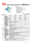
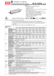
Über die gesetzliche Gewährleistung hinausgehende Garantieangaben sind Herstellergarantien. DRA-60 60W Single Output Switching Power Supply LPS ■ Features •Universal AC input / Full range •Protections: Short circuit / Overload / Over voltage •Can be installed on DIN rail TS-35/7.5 or 15 •Voltage adjustable through internal potentiometer •Current adjustable through external 1~10Vdc, PWM signal series Bauar t gepruft Sicherheit egel ma ge od o s be wac g www.tuv.com ID 2000000000 ■ Applications Machine vision inspection system Plant cultivation system or resistance •Cooling by free air convection Pass LPS •LED indicator for power on •100% full load burn-in test •3 years warranty ■ Description DRA-60 is one 60W AC/DC DIN rail power supply, featuring the adjustable output current, particularly targeting industrial inspection equipments involving LED dimming application. Users are able to easily change the constant output current level, or the LED dimming level, via 1~10Vdc, PWM signal or resistance. DRA-60 can be mounted on DIN rail TS-35/7.5 or 15; in addition, the width of the unit is only 40mm that it is well suited for the installation in a limited spacing. DRA-60 accepts the universal AC input between 90VAC and 264VAC; the efficiency is up to 87% that the entire series can operate, under free air convection, from -30 ℃ through 70 ℃ . ■ Model Encoding DRA - 60 - 12 Output voltage Output wattage Series name File Name:DRA-60-SPEC 2014-09-13 Über die gesetzliche Gewährleistung hinausgehende Garantieangaben sind Herstellergarantien. DRA-60 60W Single Output Switching Power Supply series SPECIFICATION MODEL DC VOLTAGE OUTPUT DRA-60-12 DRA-60-24 12V 24V CONSTANT CURRENT REGION 3 ~ 12V 3 ~ 24V RATED CURRENT 5A 2.5A CURRENT RANGE 0 ~ 5A 0 ~ 2.5A RATED POWER 60W 60W RIPPLE & NOISE (max.) Note.2 120mVp-p 150mVp-p VOLTAGE ADJ. RANGE 24 ~ 30V 12 ~ 15V VOLTAGE TOLERANCE Note.3 ±1.0% ±1.0% LINE REGULATION ±0.5% ±0.5% LOAD REGULATION ±0.5% ±0.5% SETUP, RISE TIME Note.4 400ms, 90ms/230VAC INPUT HOLD UP TIME (Typ.) 50ms/230VAC VOLTAGE RANGE 90 ~ 264VAC FREQUENCY RANGE 47 ~ 63Hz EFFICIENCY (Typ.) 85% AC CURRENT (Typ.) 1.3A/115VAC INRUSH CURRENT (Typ.) OVERLOAD PROTECTION OVER VOLTAGE 800ms, 90ms/115VAC at full load 10ms/115VAC at full load 127 ~ 370VDC [DC input operation possible by connecting AC/L(+), AC/N(-)] 87% 0.8A/230VAC COLD START 30A/115VAC 60A/230VAC 95 ~ 108% rated output power Protection type : Constant current limiting, recovers automatically after fault condition is removed 14.49 ~ 18.63V 28.98 ~ 37.26V Protection type : Shut down o/p voltage, re-power on to recover WORKING TEMP. -30 ~ +70℃ (Refer to "Derating Curve") WORKING HUMIDITY 20 ~ 90% RH non-condensing ENVIRONMENT STORAGE TEMP., HUMIDITY -40 ~ +85℃, 10 ~ 95% RH TEMP. COEFFICIENT ±0.03%/℃ (0 ~ 50℃) on output VIBRATION 10 ~ 500Hz, 2G 10min./1cycle, 60min. each along X, Y, Z axes SAFETY STANDARDS UL60950-1, TUV EN60950-1 approved I/P-O/P:3KVAC I/P-FG:2KVAC O/P-FG:0.5KVAC SAFETY & WITHSTAND VOLTAGE EMC ISOLATION RESISTANCE I/P-O/P, I/P-FG, O/P-FG:100M Ohms / 500VDC / 25℃/ 70% RH (Note 5) Compliance to EN55022 (CISPR22) Class B, EN61000-3-2,-3 EMC EMISSION EMC IMMUNITY MTBF OTHERS DIMENSION PACKING NOTE Compliance to EN61000-4-2,3,4,5,6,8,11, EN55024, EN61204-3, light industry level, criteria A 436.4K hrs min. MIL-HDBK-217F (25℃) 40*90*100mm (W*H*D) 0.3Kg; 42pcs/13.6Kg/0.82CUFT 1. All parameters NOT specially mentioned are measured at 230VAC input, rated load and 25℃ of ambient temperature. 2. Ripple & noise are measured at 20MHz of bandwidth by using a 12" twisted pair-wire terminated with a 0.1uf & 47uf parallel capacitor. 3. Tolerance : includes set up tolerance, line regulation and load regulation. 4. Length of set up time is measured at cold first start. Turning ON/OFF the power supply may lead to increase of the set up time. 5. The power supply is considered a component which will be installed into a final equipment. The final equipment must be re-confirmed that it still meets EMC directives. For guidance on how to perform these EMC tests, please refer to EMI testing of component power supplies. (as available on http://www.meanwell.com) 6. Installation clearances : 40mm on top, 20mm on the bottom, 5mm on the left and right side are recommended when loaded permanently with full power. In case the adjacent device is a heat source, 15mm clearance is recommended. File Name:DRA-60-SPEC 2014-09-13 Über die gesetzliche Gewährleistung hinausgehende Garantieangaben sind Herstellergarantien. DRA-60 60W Single Output Switching Power Supply series Block Diagram RECTIFIERS & FILTER EMI FILTER I/P RECTIFIERS & FILTER POWER SWITCHING +V -V DIM+ DIM- O.C.P. DETECTION CIRCUIT FG CONTROL O.L.P. O.V.P. Derating Curve Static Characteristics 100 100 90 80 80 230VAC Input only 70 LOAD (%) LOAD (%) 60 40 20 -30 -20 0 15 30 40 50 60 60 50 40 70 (VERTICAL) 90 100 125 135 145 155 165 175 180 200 230 264 INPUT VOLTAGE (V) 60Hz AMBIENT TEMPERATURE (℃) LED DIMMING/OUTPUT CURRENT ADJUSTMENT OPERATION ※ Built in 3 in 1 LED dimming function or output current adjustment. Output constant current level can be adjusted by applying 1 ~ 10Vdc, 10V PWM signal or resistance between DIM+ and DIM-. ※ Please DO NOT connect "DIM-" to "-V". ※ Reference resistance value for output current adjustment (Typical) 10KΩ 20KΩ 30KΩ 40KΩ 50KΩ 60KΩ 70KΩ 80KΩ 90KΩ 100KΩ Single driver Resistance Multiple drivers value 10KΩ/N 20KΩ/N 30KΩ/N 40KΩ/N 50KΩ/N 60KΩ/N 70KΩ/N 80KΩ/N 90KΩ/N 100KΩ/N (N=driver quantity for synchronized dimming operation) Percentage of rated current 10% OPEN ----- 20% 30% 40% 50% 60% 70% 80% 90% 100% 102%~108% ※ 1 ~ 10Vdc for output current adjustment (Typical) Applied Source 1V 2V 3V 4V 5V 6V 7V 8V 9V 10V OPEN Percentage of rated current 10% 20% 30% 40% 50% 60% 70% 80% 90% 100% 102%~108% ※ 10V PWM signal for output current adjustment (Typical): Frequency range :100Hz ~ 3KHz Duty value 10% 20% 30% 40% 50% 60% 70% 80% 90% 100% OPEN Percentage of rated current 10% 20% 30% 40% 50% 60% 70% 80% 90% 100% 102%~108% ※For LED dimming operation, direct connection to LEDs is suggested, but is not suitable for using additional drivers. File Name:DRA-60-SPEC 2014-09-13 Über die gesetzliche Gewährleistung hinausgehende Garantieangaben sind Herstellergarantien. DRA-60 60W Single Output Switching Power Supply series ※Using the built-in dimming function can't turn the lighting fixture totally dark. Please refer to the connection method below to achieve 0% brightness of the lighting fixture connecting to the LED power supply unit. Using a switch and relay can turn ON/OFF the lighting fixture. 10K~100K Ohms resistance 1~10V DC Voltage 10V PWM Signal LOAD +V +V -V -V DIMDIM+ Adjuster Switch + +V ADJ Relay N L L FG N DRIVING METHODS OF APPLICATIONS INVOLVING LED The power supply may either work in "constant voltage mode or constant current mode" to drive the LEDs. In the constant current region, the highest voltage at the output of the driver depends on the configuration of the end systems. Rated output voltage (B) Constant Current area (A) Constant Voltage area Should there be any compatibility issues, please contact MEAN WELL. Vo(v) 3V (C) Hiccup Protection 50 100 Io (%) File Name:DRA-60-SPEC 2014-09-13 Über die gesetzliche Gewährleistung hinausgehende Garantieangaben sind Herstellergarantien. DRA-60 60W Single Output Switching Power Supply series Mechanical Specification Case No.962A 79 40 5 5 5 5 5 DIM+ DIM- +V +V -V -V Unit:mm 90 + +V ADJ N L 7.5 7.5 Installation Instruction 35 This series fits DIN rail TS35/7.5 or TS35/15. For installation details, please refer to the USER MANUAL on http://www.meanwell.com/search/DRA-60/DRA_manual.pdf (This diagram is for reference. The rail is not included with unit.) Back View File Name:DRA-40-SPEC 2014-09-13