1
PATH ATMS Center
Ramp Metering Control Plugin
PARAMICS Plugin Document –
Ramp metering control
Lianyu Chu Henry X. Liu Will Recker
PATH ATMS Center
University of California, Irvine
Plugin Compatibility: V3/V4
Release date: 3/20/2003
522 Social Science Tower
Irvine, CA 92697-3600
URL: http://www.its.uci.edu/
1
PATH ATMS Center
Ramp Metering Control Plugin
Table of Contents
Table of Contents.............................................................................................................2
1. Introduction..................................................................................................................3
2 Plugin implementation..................................................................................................4
2.1 Real-world ramp metering system.........................................................................4
2.2 Modeling vehicle detection....................................................................................4
2.3 Control logic ..........................................................................................................5
2.4 Pseudo code............................................................................................................6
3. Step-by-step user manual.............................................................................................8
3.1 Data preparation.....................................................................................................8
3.2 Adding demand detectors.......................................................................................8
3.3 Adding on-ramp signal through editing “priorities” file........................................8
3.4 Preparation of “ramp_control”...............................................................................9
3.5 Loading plugin .....................................................................................................10
3.6 Error checking......................................................................................................10
4. PROGRAMMER capabilities ....................................................................................12
4.1 Interface functions ................................................................................................12
4.2 How to use interface functions in other plugins ..................................................13
5 Technical Supports......................................................................................................14
5.1 Limitations of this plugin .....................................................................................14
5.2 FAQ......................................................................................................................14
5.3 Contact information .............................................................................................15
5.4 References ............................................................................................................15
2
PATH ATMS Center
Ramp Metering Control Plugin
1. Introduction
There have been a number of strategies to release vehicles into the mainline freeway
traffic, each with different demands on sophistication of control and detectorization.
Caltrans currently has three ramp metering systems, SATMS, SDRMS, and SJRMS. All
of them use the 170 type controllers as hardware. SATMS, SDRMS, and SJRMS are
names of their software algorithms installed in the 170 controller.
This plugin is designed to model pre-timed ramp metering control on n-cars-per-green
basis (with n > 1) in PARAMICS. It also supports multiple timing plans and the use of
ramp detectors for metering control. The data input of this plugin is a time-of-day ramp
control plan and the detector information of each meter.
In addition, this plugin is designed to support the development of advanced rampmetering algorithms, and integrated control strategies (ramp metering plus arterial signal
control). A number of interface functions are provided by this plugin for external plugin
modules to acquire the current metering rate and set a new metering rate to a specific
ramp meter.
3
PATH ATMS Center
Ramp Metering Control Plugin
2 Plugin implementation
2.1 Real-world ramp metering system
The easiest ramp meter is based on fixed-time control. Some latest ramp metering design
has included the check- in and check-out detector for a better control and the
consideration of safety.
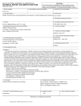
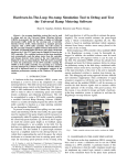
Caltrans has the following basic design of ramp metering system. Five types detectors
can be possibly installed for a ramp meter, including on-ramp detector, demand detector,
passage detector, queue detector, and ramp HOV detector. The on-ramp detector is used
for counting total number of vehicles entering freeway from entrance ramps. The demand
and passage detectors (i.e. corresponding to the check- in and check-out detectors) are
used for the operation of on-ramp signals. The demand detector employs to initiate green
and the passage detector employs to return the signal to red. The queue detector is located
at the upstream end of the entrance ramp, used for detecting the excessive queue length in
order to avoid interference with the arterial traffic. The ramp HOV detector is used for
counting the number of carpool vehicles entering freeway from entrance ramps.
Figure 1 Typical ramp metering configuration
2.2 Modeling vehicle detection
This plugin is designed to implement the easiest ramp metering control, i.e. pre-timed
control. Only the time-of-day metering plan is the necessary information required by the
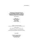
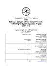
plugin. The plugin can also work with the use of detectors. The check- in and check-out
logic of the real-world ramp metering system needs accurate detection of passing vehicles.
However, simulation suffers the problem of missing vehicles. We decide to only use one
4
PATH ATMS Center
Ramp Metering Control Plugin
check- in detector (or, demand detector). The simplified layout of ramp metering system
is shown in Figure 2.
Mainline Traffic
op
St
ne
La
r
to
ec
t
de
Figure 2. A typical ramp metering layout
The length of the demand detector is based on the real- world design of ramp meter.
Based on the design manual of Caltrans, District 11 typically uses 4 demand loops,
Districts 3, 4, 6, 8 typically use 3 demand loops, Districts 7, 12 typically use 2 demand
loops. As a result, the length of the demand detector is equal to the length that a demand
detector can cover.
2.3 Control logic
The ramp signal generally provides two indications, green and red. Based on the time-ofday metering rate, the metering cycle can be calculated as:
cycle = 3600 / rate
If one-car-per-green is applied, we assume the green time a vehicle needs to pass the
metering signal is 2 seconds. If two-car-per-green is applied, we assume the green time
for two vehicles to pass the metering signal is 4 seconds. Then the length of red signal is:
red = cycle − green
If there is no demand detector or check- in detector, metering signal will show red and
green based on the above red and green time. This guarantees that vehicles are released
from ramp to the mainline freeway at a fixed ramp metering rate.
5
PATH ATMS Center
Ramp Metering Control Plugin
If there is a demand detector or check- in detector, every vehicle has to stop before the
stop lane, waiting for the green signal. The detector for sensing the presence of a vehicle
allows the signal to rest in red, avoiding potential confusion to a driver approaching the
signal, due to the short greens. The following three principles are used for metering signal
control:
(1) If the length of red signal is longer than “red” and the demand detector has
detected the presence of a vehicle waiting, the green signal will be given with the
length of “green”.
(2) If the length of red signal is shorter than “red”, green signal will not be given even
there are waiting vehicles.
(3) If the length of red signal is longer than “red” and no vehicle is waiting, the
metering signal keeps showing the red signal.
This plugin allows multiple metering plans. A metering rate is fixed within a specific
time window. For another time window, another timing plan can apply.
As an illustration, suppose the ramp signal cycle length is 10 seconds from 4pm to 6pm.
This is one vehicle every 10 seconds, so that a setting of a 2 sec of green followed by 8
sec of red could be used. The metering rate in this case is 360 vph.
2.4 Pseudo code
The control logic is given in the following pseudo codes:
(1) Plugin initialization
Read in all ramp information.
Allocate memories for all pointers to be used.
Store all necessary ramp information to global data structures.
Check the existence of ramp nodes and correspondent detectors.
Initialize the ramp signals based on the initial simulation time.
(2) Main program
Get simulation time.
For controlled ramp = 1 : n
{
Check the current running phase.
Get green left time of the current running phase
Find the correct ramp control plan according to the simulation time
If (ramp cycle length changed due to entering another time period)
{
Notify the operator
15
Recalculate the green times for the 2 phases
}
If (controltype is always ON)
set next green time for “always ON”
6
PATH ATMS Center
Ramp Metering Control Plugin
Else if (controltype is always OFF)
set next green time for “always OFF”
Else
{
If ( the running phase is 2 && green left time <= time step )
Set the next green time for phase 1
Else if (the running phase is 1)
{
If (no vehicle presence)
{
If(the running time is less than RAMP_CYCLE)
continue to increment green time for phase 1
Else (the running time is equal to RAMP_CYCLE)
set the next green time for phase 2
}
else
Set the next green time for phase 2
}
}
}
7
PATH ATMS Center
Ramp Metering Control Plugin
3. Step-by-step user manual
In order to use this ramp metering plugin, two files need to be prepared:
(1) “priorities” file is a system file of PARAMICS, provided with the action and
phase definition of a ramp signal.
(2) “ramp_control” file is the input of actuated ramp API including the ramp control
information, such as ramp name, control type, cycle, effective time, etc.
3.1 Data preparation
The following documents are required in order to correctly use this plugin.
(1) Ramp meter design map, including the layout of detectors
(2) Entrance ramp control plans, obtained from the proper government agency
3.2 Adding demand detectors
The demand detector should be added to the PARAMICS network, which should be put
just before the stop line based on the design map of the entrance ramp. The number of
demand loops installed in the real world and the layout of these loops will decide the
length of the demand detector in PARAMICS.
The ramp metering API can work with or without detectors. If with detectors, the plugin
requires a demand detector, which should be specified by users in the “ramp_control” file,
for the operation of on-ramp signal. If without detectors, users need to specify the
demand detector of the on-ramp as N/A.
3.3 Adding on-ramp signal through editing “priorities” file
In order to let PARAMICS regard a node as a signalized node, users must add or edit the
“priorities” information of the node. This can be realized through GUI or editing
“priorities” file. The “priorities” file, a system file of PARAMICS, defines movements of
each phase of a signalized intersection. We recommend the latter method.
There are two phases for each on-ramp signal. We define that phase 1 is the red signal to
prohibit vehicles from entering the mainline freeway and phase 2 is the green signal to
release the waiting vehicle into the freeway. An example of the “priorities” information
fro an on-ramp signal is as follows:
actions 92
phase offset 0.00 sec
phase 1
0.00
max 30.00
8
PATH ATMS Center
Ramp Metering Control Plugin
red phase 0.00
fill
all barred except
phase 2
0.00
max 30.00
red phase 0.00
fill
all barred except
from 91 to 93 major
Where fill means no yellow will be shown. The initial phase lengths for both phases are
set to 0. This plugin has set the maximum cycle of an on-ramp signal to 24 seconds.
Currently in the above example, “max 30.00” means the maximum length of each phase
is 30 seconds. This value should be larger than 24 seconds in order to make ramp meters
controlled by this plugin.
3.4 Preparation of “ramp_control”
The “ramp_control” file includes the ramp control information, which is the input of this
plugin. It should be located at the same directory as any other network files. An example
of “ramp_control” is shown below.
total number of controlled entrance ramps is
control cycle of ramp metering
7
30
on-ramp signal
name
demand detector
number of control plans
from 6:0 to 9:0
from 15:0 to 19:0
33
405N & ICD 1 @ 0.93
405n0.93orb
2
METER_ON with 1 veh per 6 sec
METER_ON with 1 veh per 6 sec
on-ramp signal
name
demand detector
number of control plans
from 6:0 to 9:0
from 15:0 to 19:0
…
36
405~N & ICD 2 @ 1.11
405n1.11orb
2
METER_ON with 1 veh per 12 sec
METER_ON with 1 veh per 7 sec
The first line defines the number of entrance ramps to be controlled by this plugin. The
second line defines the control cycle of the ramp metering control.
9
PATH ATMS Center
Ramp Metering Control Plugin
The following is the necessary input information of each entrance ramp, which always
begins from a blank line.
(1) “on-ramp signal” is the global node number of the on-ramp signal in the
PARAMICS network.
(2) “name” is the description of the entrance ramp, such as its location.
(3) “demand detector” is the name of the demand detector of the entrance ramp. If
there is no demand detector or the demand detector is not used for on-ramp signal
operation, please specify as “N/A”. If the specified detector can not be found in
the “detectors” file, a warning message will be given and the entrance ramp will
be operated without demand detector.
(4) ”number of control plans” is the number of on-ramp signal control plans. The
number will decide how many timing plans followed.
(5) The following are time-of-day timing plans. The possible format might be one of
the following:
from TIME1 to TIME2
from TIME1 to TIME2
from TIME1 to TIME2
METER_ON with BB veh per CC sec
METER_OFF
RAMP_CLOSURE
where “TIME1” is the starting time of a timing period and “TIME2” is the end
time of a timing period. The format of TIME1 and TIME2 is HH:MM (only hour
and minute is specified). The timing periods of any two timing plans should not
overlap. “BB” is the type of metering operation, single-entry metering (BB = 1) or
platoon metering (BB = 2). “CC” is the cycle of metering control. If the status is
METER_ON, BB and CC should be specified. If there is no timing plan for a
certain time period, it is regarded as METER_OFF.
3.5 Loading plugin
After the completion of the “ramp_control” file and the update the “priorities” file, you
can load the simulation network together with this plugin. The names of this plugin files
are:
ramp_controller.dll: Modeller Plugin
ramp_controller-p.dll: Processor Plugin
Run simulation and then you will see that this plugin is used to emulate the ramp
metering control at specified ramps via GUI.
3.6 Error checking
10
PATH ATMS Center
Ramp Metering Control Plugin
This plugin can work if “ramp_control” and “priorities”are prepared correctly. If any
mistakes happened in the “ramp_control” file, the plugin will be disabled. The report
window of PARAMICS will show whether this plugin is working.
If the metering control is not working or is not working as you expected, you may need to
check if there is any error in the “ramp_control” file. This plugin generates a file named
“Log-ramp.txt” under the network directory, which can be used for this purpose.
11
PATH ATMS Center
Ramp Metering Control Plugin
4. PROGRAMMER capabilities
4.1 Interface functions
There are three interface functions, used for querying current and time-of-day metering
rate and setting a new metering rate. An advanced ramp- metering algorithm API can be
developed based on them. Their prototypes are shown below.
RAMP *uci_ramp_get_parameters (char *rampnode)
Function:
Querying the current metering plan of a specific ramp meter.
Return Value: The current metering control plan of an on-ramp signal.
Parameters: rampnode is the name of an on-ramp signal node.
RAMP is the structure of ramp control data, whose definition is:
typedef struct Ramp_data RAMP;
struct Ramp_data
{
// on-ramp signal node name and its location
char *node;
char *name;
// ramp control types and parameters
int type;
int cycle;
};
Where controlType is the status (or type) of the ramp metering control,
which can be 0 (if RAMP_CLOSURE), 1 (if RAMP_ON with single-entry
metering), 2 (if RAMP_ON with platoon metering) and 9 (if RAMP_OFF).
void uci_ramp_set_parameters (RAMP *ramp, Bool parameter)
Function:
Setting a new metering rate to a specific ramp meter.
Return Value: None
Parameters: ramp stores the new metering control data of a specific on-ramp; status is
a Boolean value. parameter = TRUE means to set a new metering rate
based on an external algorithm; parameter = FALSE means to restore the
default time-of-day timing plans.
float uci_ramp_get_tod_rate(char *rampnode)
Function:
Querying the current time-of-day metering plan of a specific ramp meter.
Return Value: The current time-of-day metering plan of an on-ramp signal
TOD rate = 0: ramp_off
TOD rate = 1: metering_off
others: metering_rate
Parameters: rampnode is the name of an on-ramp signal node.
12
PATH ATMS Center
Ramp Metering Control Plugin
4.2 How to use interface functions in other plugins
These interface functions can be called in other plugins. The following setting is required:
(1) In the workspace of your plugin that wants to use these interface functions,
specify the library file “ramp_controller.lib” of the actuated signal plugin as an
input object/library module. The path of “ramp_controller.lib” should be specified
as well.
(2) Specify the prototype of the interface function at the beginning of your plugin as
follows:
_declspec(dllimport) void uci_ramp_set_parameters (RAMP *ramp, Bool parameter);
_declspec(dllimport) RAMP *uci_ramp_get_parameters (char *rampnode);
_declspec(dllimport) float uci_ramp_get_tod_rate(char *rampnode);
13
PATH ATMS Center
Ramp Metering Control Plugin
5 Technical Supports
5.1 Limitations of this plugin
The controllers in the real world have more capabilities than this plugin. For example,
SATMS (one of Caltrans’ ramp metering algorithm) contains local mainline responsive
control (i.e. demand-capacity control) and time-of-day control (i.e. pre-timed control).
However, this plugin only emulates pre-timed control.
In version 3 of PARAMICS, sometimes the presence detector does not work correctly, i.e.
sometimes a vehicle cannot be detected though it is present on the detector. This case is
very rare, however, this may cause severe problems in the simulation since all the
following vehicles are blocked, and the signal may remain red all the time. To solve this
problem, a green signal is given as long as the time of red signal is over RAMP_CYCLE.
The maximum number of timing plans is 256 for each entrance ramp signal. The length
of green time for single-entry metering is 2.0 seconds and for platoon metering is 4.0
seconds, which are pre-set by the plugin.
No queuing control is involved in this plugin. If a queue control is required, please use
queue control plugin together with this API.
5.2 FAQ
1. Grammar of input files
Unlike the parser system of PARAMICS, which allow flexible grammars and comments
(i.e. ##), the format of the input file of this plugin is rigid and thus any problem in the file
may cause the plugin not work well. Our recommendation for users is that the input file
of the example network of this plugin is a good starting point to make your own input file
in order to avoid editing problems.
2. PARAMICS can model ramp metering. Why do you develop this plugin?
PARAMICS can model fixed-time ramp metering with multiple timing plans. However, a
ramp- metering controller, developed in PARAMICS API, is required for the support of
development of adaptive ramp metering algorithms, which have more complicated
control logics. The ramp- metering controller should provide interface functions that can
be used for querying the old metering rate and setting a new metering rate based on the
adaptive ramp metering algorithms. When the adaptive ramp- metering algorithm is not
activated, the fixed-time metering will be the default control.
3. In “priorities” file, the two phases of ramp signal node has the input of “max 18.00”,
will this setting affect meters controlled by this plugin?
14
PATH ATMS Center
Ramp Metering Control Plugin
Yes. These meters will not work correctly. The reason is described in Section 3.3. Our
recommended value is “max 30.00”.
4. About advanced ramp metering algorithm
This plugin is the ramp metering controller of any advanced ramp- metering algorithm
(such as ALINEA or BOTTLENECK), used for providing current metering rate and
setting a new metering rate based on the request of the advanced algorithm. If an
advanced algorithm is associated with an entrance ramp, more detectors, such as the
queue detector, HOV detector, on-ramp detector, might be required.
5.3 Contact information
Any comments and suggestions are welcome. Please contact us at the email address:
[email protected].
5.4 References
(1) Liu, X., Chu, L., and Recker, W. (2001) Paramics API Design Document for
Actuated Signal, Signal Coordination and Ramp Control, California PATH
Working Paper, UCB-ITS-PWP-2001-11, University of California at Berkeley.
(2) Chu, L., Liu, X., and Recker, W. (2003) Development of the Capability-Enhanced
PARAMICS Simulation Environment, presented at TRB 2003 annual meeting.
15