1
STATE OF CALIFORNIA • DEPARTMENT OF TRANSPORTATION
TECHNICAL REPORT DOCUMENTATION PAGE
TR0003 (REV 10/98)
1. REPORT NUMBER
ADA Notice
For individuals with sensory disabilities, this document is available in alternate
formats. For information call (916) 654-6410 or TDD (916) 654-3880 or write
Records and Forms Management, 1120 N Street, MS-89, Sacramento, CA 95814.
2. GOVERNMENT ASSOCIATION NUMBER
3. RECIPIENT'S CATALOG NUMBER
CA14-2517
4. TITLE AND SUBTITLE
5. REPORT DATE
Mobile Terrestrial Laser Scanning Workflow Development, Technical Support and Evaluation June 14, 2014
6. PERFORMING ORGANIZATION CODE
7. AUTHOR
8. PERFORMING ORGANIZATION REPORT NO.
Kin Yen, Bahram Ravani, and Ty A. Lasky
UCD-ARR-14-06-14-01
9. PERFORMING ORGANIZATION NAME AND ADDRESS
10. WORK UNIT NUMBER
AHMCT Research Center
UCD Dept. of Mechanical & Aerospace Engineering
Davis, California 95616-5294
11. CONTRACT OR GRANT NUMBER
65A0416, Task 2517
13. TYPE OF REPORT AND PERIOD COVERED
Final Report
October 2012 – June 2014
12. SPONSORING AGENCY AND ADDRESS
California Department of Transportation
P.O. Box 942873, MS #83
Sacramento, CA 94273-0001
14. SPONSORING AGENCY CODE
Caltrans
15. SUPPLEMENTARY NOTES
16. ABSTRACT
This report documents the research project “Mobile Terrestrial Laser Scanning Workflow Development, Technical Support and
Evaluation.” The primary goal of this project was to develop best practices of Mobile Terrestrial Laser Scanning (MTLS) data collection.
MTLS combines the use of a laser scanner(s), the Global Navigation Satellite Systems (GNSS), an Inertial Measurement Unit (IMU), and a
Distance Measuring Instrument (DMI) on a mobile platform to collect accurate and precise geospatial data. A previous study by the
Advanced Highway Maintenance and Construction Technology (AHMCT) Research Center in collaboration with the Caltrans Office of
Land Surveys (OLS) tested and determined the feasibility of using this technology for some Caltrans applications in highway maintenance
and construction. The current effort involved experimental evaluation and field testing of this technology as well as basic research on its
improvement and its integration into Caltrans workflow. The objective of the research was to facilitate effective deployment of the MTLS
system in Northern California in conjunction with Caltrans OLS. AHMCT researchers were involved in the MTLS system vehicle
integration, data collection training, training material development, documentation of best practices and workflow for MTLS data collection,
utilization analysis, and MTLS impact study. Key contributions of this research project included:
• Report on MTLS system installation
• Report on MTLS usage results, analysis, and lessons learned.
• Best practices, workflow, and training documentation for MTLS data collection.
• Lessons learned from MTLS deployment and training
• Scanning wet concrete and asphalt pavement testing
• Development of a photolog viewer
• Recommendations and future work.
17. KEY WORDS
18. DISTRIBUTION STATEMENT
LiDAR, Mobile Terrestrial Laser Scanning
No restrictions. This document is available to the
public through the National Technical Information
Service, Springfield, Virginia 22161.
19. SECURITY CLASSIFICATION (of this report)
20. NUMBER OF PAGES
200
Unclassified
Reproduction of completed page authorized
Copyright 2015, AHMCT Research Center, UC Davis
21. COST OF REPORT CHARGED
DISCLAIMER/DISCLOSURE STATEMENT
The research reported herein was performed as part of the Advanced Highway Maintenance
and Construction Technology (AHMCT) Research Center, within the Department of Mechanical
and Aerospace Engineering at the University of California – Davis, and the Division of
Research, Innovation and System Information at the California Department of Transportation. It
is evolutionary and voluntary. It is a cooperative venture of local, State and Federal governments
and universities.
This document is disseminated in the interest of information exchange. The contents of this
report reflect the views of the authors who are responsible for the facts and accuracy of the data
presented herein. The contents do not necessarily reflect the official views or policies of the State
of California, the Federal Highway Administration, or the University of California. This
publication does not constitute a standard, specification or regulation. This report does not
constitute an endorsement of any product described herein.
For individuals with sensory disabilities, this document is available in Braille, large print,
audiocassette, or compact disk. To obtain a copy of this document in one of these alternate
formats, please contact: the Division of Research, Innovation and System Information, MS-83,
California Department of Transportation, P.O. Box 942873, Sacramento, CA 94273-0001.
Copyright 2015, AHMCT Research Center, UC Davis
Advanced Highway Maintenance
and Construction Technology
Research Center
Department of Mechanical and Aerospace Engineering
University of California at Davis
Mobile Terrestrial Laser Scanning Workflow
Development, Technical Support and Evaluation
Kin Yen, Bahram Ravani &
Ty A. Lasky: Principal Investigator
Report Number: CA14-2517
AHMCT Research Report: UCD-ARR-14-06-14-01
Final Report of Contract: IA65A0416, Task 2517
June 14, 2014
California Department of Transportation
Division of Research, Innovation and System Information
Copyright 2015, AHMCT Research Center, UC Davis
Mobile Terrestrial Laser Scanning Workflow Development, Technical Support and Evaluation
ABSTRACT
This report documents the research project “Mobile Terrestrial Laser Scanning Workflow
Development, Technical Support and Evaluation.” The primary goal of this project was to
develop best practices of Mobile Terrestrial Laser Scanning (MTLS) data collection. MTLS
combines the use of a laser scanner(s), the Global Navigation Satellite Systems (GNSS), an
Inertial Measurement Unit (IMU), and a Distance Measuring Instrument (DMI) on a mobile
platform to collect accurate and precise geospatial data. A previous study by the Advanced
Highway Maintenance and Construction Technology (AHMCT) Research Center in
collaboration with the Caltrans Office of Land Surveys (OLS) tested and determined the
feasibility of using this technology for some Caltrans applications in highway maintenance and
construction. The current effort involved experimental evaluation and field testing of this
technology as well as basic research on its improvement and its integration into Caltrans
workflow. The objective of the research was to facilitate effective deployment of the MTLS
system in Northern California in conjunction with Caltrans OLS. AHMCT researchers were
involved in the MTLS system vehicle integration, data collection training, training material
development, documentation of best practices and workflow for MTLS data collection,
utilization analysis, and MTLS impact study. Key contributions of this research project included:
•
Report on MTLS system installation
•
Report on MTLS usage results, analysis, and lessons learned.
•
Best practices, workflow, and training documentation for MTLS data collection.
•
Lessons learned from MTLS deployment and training
•
Scanning wet concrete and asphalt pavement testing
•
Development of a photolog viewer
•
Recommendations and future work.
ii
Copyright 2015, AHMCT Research Center, UC Davis
Mobile Terrestrial Laser Scanning Workflow Development, Technical Support and Evaluation
TABLE OF CONTENTS
Table of Contents .................................................................................................................... iii
List of Figures ......................................................................................................................... vi
List of Tables ........................................................................................................................... ix
Code Listings ............................................................................................................................ x
List of Acronyms and Abbreviations ...................................................................................... xi
Acknowledgments.................................................................................................................. xiii
Chapter 1: Introduction ........................................................................................................... 1
Problem ............................................................................................................................................. 1
Background....................................................................................................................................... 4
Research Approach .......................................................................................................................... 4
Overview of Research Results ......................................................................................................... 4
Chapter 2: Vehicle Integration ................................................................................................ 5
Background....................................................................................................................................... 5
Trimble MX8 MTLS System Description ...................................................................................... 5
Vehicle Integration ........................................................................................................................... 8
System Calibration ........................................................................................................................... 9
Lessons Learned ............................................................................................................................... 9
Chapter 3: Training ............................................................................................................... 14
Background..................................................................................................................................... 14
Recommendations .......................................................................................................................... 14
Chapter 4: Caltrans MTLS Deployment Status and Usage.................................................. 16
Caltrans MTLS Usage ................................................................................................................... 16
Chapter 5: Best Practices and Workflow .............................................................................. 21
Rolling Lane Closure Best Practices ............................................................................................ 23
GNSS Base Station Setup Best Practices ..................................................................................... 24
Geo-referencing and Registration Ground Targets .................................................................... 25
Data Archive Recommendations .................................................................................................. 29
Chapter 6: Photolog Viewer .................................................................................................. 30
Overview ......................................................................................................................................... 30
Photolog Viewer Prototype............................................................................................................ 30
Input Data Requirements .............................................................................................................. 35
Utilities and Workflow to Convert MTLS Data to Photolog ..................................................... 36
Chapter 7: MTLS Impact Study ............................................................................................ 39
iii
Copyright 2015, AHMCT Research Center, UC Davis
Mobile Terrestrial Laser Scanning Workflow Development, Technical Support and Evaluation
Beneficial Impacts .......................................................................................................................... 39
Institutional Challenges ................................................................................................................. 40
Data Management Challenges ...................................................................................................... 42
Chapter 8: Conclusions and Future Research ..................................................................... 47
Recommendations and Lesson Learned Summary ..................................................................... 48
Future Research ............................................................................................................................. 49
References .............................................................................................................................. 51
Appendix A: Caltrans Trimble MX8 Operation Manual ..................................................... 52
Caltrans Trimble MX8 MTLS System Description .................................................................... 52
MTLS Mission Planning ................................................................................................................ 55
MX8 Startup Procedures............................................................................................................... 58
System Shutdown Procedure ........................................................................................................ 79
Data Transfer ................................................................................................................................. 80
Uninstalling and Installing DMI ................................................................................................... 82
DMI Calibration............................................................................................................................. 85
Laser Alignment Calibration ........................................................................................................ 85
Tool List for Caltrans MX8 System/Vehicle Maintenance......................................................... 86
Appendix B: Caltrans Trimble MX8 Vehicle Checklist Version 1.09.................................. 87
Appendix C: Caltrans MTLS system Scan on Wet Pavement Test Results ......................... 89
Wet Asphalt Scanning Performance Test Setup ......................................................................... 90
Scan on Wet Concrete Surface Setup ........................................................................................... 99
Appendix D: Photolog Code Listings .................................................................................. 105
Photolog Viewer Code ................................................................................................................. 106
Code for Scripts and Utilities for Conversion from MTLS Data to Photolog ........................ 131
Appendix E: LASZIP Python Wrapper Utility ................................................................... 157
Overview ....................................................................................................................................... 157
LAS Archive Tool......................................................................................................................... 157
How to Distribute LAS Archive Tool ......................................................................................... 158
Appendix F MTLS Specifications ....................................................................................... 170
Technical Requirements for Mobile Terrestrial Laser Scanning (MTLS) System ................ 171
Appendix G MTLS Personnel Skills Descriptions .............................................................. 176
MTLS Vehicle Driver .................................................................................................................. 176
MTLS Operator ........................................................................................................................... 178
MTLS Data Post-processing Personnel ...................................................................................... 180
iv
Copyright 2015, AHMCT Research Center, UC Davis
Mobile Terrestrial Laser Scanning Workflow Development, Technical Support and Evaluation
MTLS Feature Extraction Personnel ......................................................................................... 183
v
Copyright 2015, AHMCT Research Center, UC Davis
Mobile Terrestrial Laser Scanning Workflow Development, Technical Support and Evaluation
LIST OF FIGURES
Figure 1.1. Caltrans Trimble MX8 MTLS vehicle at San Francisco-Oakland Bay Bridge Toll Plaza. ..............2
Figure 1.2. Caltrans MTLS system scan data at HWY 20 Yuba County. ..............................................................3
Figure 1.3. Caltrans MTLS system photo collection on HWY 580..........................................................................3
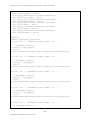
Figure 2.1. Caltrans Trimble MX8 MTLS system sensor pod and DMI ................................................................6
Figure 2.2. Caltrans Trimble MX8 MTLS system sensor pod (front view) ............................................................6
Figure 2.3. MX8 user interface (dual monitors, keyboard, and trackball) mounted next to the driver ..............7
Figure 2.4. MX8 computer rack mounted at the vehicle rear ..................................................................................7
Figure 2.5. Extra battery and battery isolators with circuit breakers added in the engine compartment ..........8
Figure 2.6. Front passenger seat modification ..........................................................................................................9
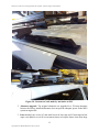
Figure 2.7. Cracks developed at the front roof rack mounts ................................................................................. 10
Figure 2.8. Custom roof rack made by mechanics at ESC ..................................................................................... 11
Figure 2.9. Liquid droplet found inside the laser scanner head ............................................................................ 12
Figure 3.1. MTLS field data collection training at HWY20 Yuba County, CA. (Performing 5-minute static
GNSS/IMU data collection at the end of the project data collection) .......................................................... 14
Figure 3.2. Caltrans MTLS deployment plan in central and southern California districts ................................ 15
Figure 4.1. MTLS deployment at HWY 580 in District 4 (Urban multi-lane highway) ...................................... 17
Figure 4.2. Number of highway miles scanned in each Caltrans district .............................................................. 17
Figure 4.3. Number of projects scanned in each Caltrans district ........................................................................ 18
Figure 4.4. Number of projects scanned by month during deployment period.................................................... 18
Figure 4.5. Point cloud collected from MTLS system ............................................................................................. 19
Figure 4.6. Caltrans MTLS system vehicle scanning on the new San Francisco-Oakland Bay Bridge before
the bridge opening ............................................................................................................................................ 19
Figure 4.7. Caltrans MTLS system vehicle on the new San Francisco-Oakland Bay Bridge during night time
scanning before the bridge opening ................................................................................................................ 20
Figure 4.8. Inside Caltrans MTLS system vehicle during a night time scanning on the new San FranciscoOakland Bay Bridge......................................................................................................................................... 20
Figure 4.9. Point cloud of the new San Francisco-Oakland Bay Bridge MTLS project ...................................... 20
Figure 5.1. MTLS data post processing data flow diagram ................................................................................... 21
Figure 5.2. Point cloud intensity value distribution before rescaling .................................................................... 22
Figure 5.3. Point cloud intensity value distribution after rescaling....................................................................... 22
Figure 5.4. Point cloud before intensity value rescaling ......................................................................................... 23
Figure 5.5. Point cloud after intensity value rescaling............................................................................................ 23
Figure 5.6. MTLS scanning supported by a chase vehicle ..................................................................................... 24
Figure 5.7. Rolling lane closure using CHP and a shadow vehicle ........................................................................ 24
Figure 5.8. Typical GNSS base station setup over local control at the project site .............................................. 25
Figure 5.9. “Cross” target on the left and reflective temporary striping tape square target on the right ......... 26
Figure 5.10. Example ground control targets located on the road shoulder ........................................................ 26
Figure 5.11. Reflectivity measurement of various reflective tape (on the right, blue is more reflective) and
photo of various reflective tape (on the left, 6” wide 3M Scotchlite reflective sheeting on top left, 4” wide
Avery Dennison reflective tape second from top, 4” wide reflective traction tape from McMaster second
from bottom left, reflective traction tape from a MTLS services provider on the bottom left). ............... 28
Figure 5.12. Dust and dirt accumulate on the square reflective tape target (on the left) and sweeping off dirt
off target (on the right) before scanning ........................................................................................................ 28
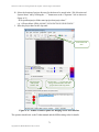
Figure 5.13. Trident Image Converter export options recommendations (DAT, TXT, SHP, TopoDOT options
checked) ............................................................................................................................................................ 29
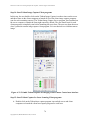
Figure 6.1. Photolog viewer prototype ..................................................................................................................... 31
Figure 6.2. Full-size uncropped front center camera image corresponding to Figure 6.1 .................................. 32
Figure 6.3. Controls and status information panel ................................................................................................. 32
Figure 6.4. Photolog select dropdown list ................................................................................................................ 33
Figure 6.5. Workflow to convert MTLS data to photolog ...................................................................................... 37
Figure 7.1. Culvert inlet in MTLS point cloud ........................................................................................................ 42
Figure A.1. Caltrans Trimble MX8 MTLS system sensor pod and DMI ............................................................. 53
Figure A.2. Caltrans Trimble MX8 MTLS system sensor pod (front view) ......................................................... 53
Figure A.3. MX8 user interface (dual monitors, keyboard, and trackball) mounted next to the driver ........... 54
vi
Copyright 2015, AHMCT Research Center, UC Davis
Mobile Terrestrial Laser Scanning Workflow Development, Technical Support and Evaluation
Figure A.4. MX8 computer rack mounted in the vehicle rear ............................................................................... 54
Figure A.5. CHP and shadow vehicle rolling traffic break .................................................................................... 56
Figure A.6. Scan line spacing vs. vehicle speed and scan rate ............................................................................... 56
Figure A.7. Xantrex inverter remote ....................................................................................................................... 59
Figure A.8. MX8 computer rack front view ............................................................................................................ 60
Figure A.9. MX8 server and client computer front view with its cover open ....................................................... 61
Figure A.10. MX8 computer rack rear view ........................................................................................................... 62
Figure A.11. Applanix POSPac LV software interface .......................................................................................... 63
Figure A.12. POSPac Removable Media Logging Control user interface ............................................................ 64
Figure A.13. POSPac Removable Media Logging Control user interface ............................................................ 64
Figure A.14. POSPac Removable Media Logging Control user interface ............................................................ 65
Figure A.15. Windows 7 control panel data source (ODBC) user interface ......................................................... 66
Figure A.16. Data source (ODBC) user interface ................................................................................................... 67
Figure A.17. ODBC user interface (select Microsoft Access Driver) .................................................................... 67
Figure A.18. ODBC interface for creating Access database link and name ......................................................... 68
Figure A.19. ODBC interface for selecting the Access project data file after clicking on the “Select” button.. 68
Figure A.20. Trimble Trident Capture for Imaging Server user interface .......................................................... 69
Figure A.21. Trimble Trident Capture for Imaging Server user interface .......................................................... 69
Figure A.22. Trimble Trident Capture for Imaging Server user interface .......................................................... 69
Figure A.23. Trimble Trident Capture for Imaging Server user interface .......................................................... 70
Figure A.24. Trimble Trident Capture for Imaging Server user interface .......................................................... 70
Figure A.25. Trimble Trident Capture for Imaging Server user interface .......................................................... 71
Figure A.26. Trident Camera Control software ..................................................................................................... 73
Figure A.27. Point Gray Research Fly Capture Camera Control user interface ................................................. 73
Figure A.28. Point Gray Research Fly Capture Camera Control user interface ................................................. 74
Figure A.29. Trimble Trident Capture for Imaging camera recording control user interface .......................... 74
Figure A.30. Trimble Trident Capture for Imaging image capture setting ......................................................... 75
Figure A.31. Set Contrast Stretch to 1 ..................................................................................................................... 75
Figure A.32. Trimble Trident Capture for Imaging Client Camera Control user interface .............................. 76
Figure A.33. Trimble Trident Capture for Laser Scanning Client user interface ............................................... 77
Figure A.34. MX8 Trident Capture for Laser Scanning user interface for setting laser configuration (server
and client computer) ........................................................................................................................................ 78
Figure A.35. Trident Capture for Laser Scanning user interface for setting laser filename prefix and suffix
(server and client computer) ........................................................................................................................... 78
Figure A.36. Trident Capture for Laser Scanning shutdown laser interface ....................................................... 79
Figure A.37. MX8 data storage hard drive (Seagate Barracuda 2TB ST2000DM001) ....................................... 81
Figure A.38. Data transfer using USB3 4 bay drive dock. ..................................................................................... 81
Figure A.39. Applanix DMI mount diagram ........................................................................................................... 82
Figure A.40. Removing Applanix DMI adapter plate mounting bolts .................................................................. 83
Figure A.41. Removing the Applanix DMI adapter plate ...................................................................................... 83
Figure A.42. Applanix DMI mounting adapter plate ............................................................................................. 84
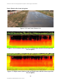
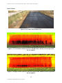
Figure C.1. Front Center Camera view of the wet asphalt pavement ................................................................... 90
Figure C.2. Left Scanner (black area has no LiDAR return, and the red area (low reflectivity) represents the
wet asphalt) ....................................................................................................................................................... 90
Figure C.3. Right Scanner (black area has no LiDAR return and the red area represents the wet asphalt) .... 90
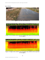
Figure C.4. Front Center Camera view ................................................................................................................... 91
Figure C.5. Left Scanner (black area has no LiDAR return, and the red area represents the wet asphalt) ..... 91
Figure C.6. Right Scanner (black area has no LiDAR return, and the red area represents the wet asphalt) ... 91
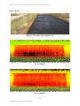
Figure C.7. Front Center Camera view ................................................................................................................... 92
Figure C.8. Left Scanner (black area has no LiDAR return, and the red area represents the wet asphalt) ..... 92
Figure C.9. Right Scanner (black area has no LiDAR return, and the red area represents the wet asphalt) ... 92
Figure C.10. Front Center Camera view ................................................................................................................. 93
Figure C.11. Left Scanner (black area has no LiDAR return, and the red area represents the wet asphalt) ... 93
Figure C.12. Right Scanner (black area has no LiDAR return, and the red area represents the wet asphalt) . 93
Figure C.13. Front Center Camera view ................................................................................................................. 94
Figure C.14. Left Scanner (black area has no LiDAR return, and the red area represents the wet asphalt) ... 94
vii
Copyright 2015, AHMCT Research Center, UC Davis
Mobile Terrestrial Laser Scanning Workflow Development, Technical Support and Evaluation
Figure C.15. Right Scanner (black area has no LiDAR return, and the red area represents the wet asphalt) . 94
Figure C.16. Front Center Camera view ................................................................................................................. 95
Figure C.17. Left Scanner (black area has no LiDAR return, and the red area represents the wet asphalt) ... 95
Figure C.18. Right Scanner (black area has no LiDAR return, and the red area represents the wet asphalt) . 95
Figure C.19. Front Center Camera view ................................................................................................................. 96
Figure C.20. Left Scanner (black area has no LiDAR return, and the red area represents the wet asphalt) ... 96
Figure C.21. Right Scanner (black area has no LiDAR return, and the red area represents the wet asphalt) . 96
Figure C.22. Front Center Camera view ................................................................................................................. 97
Figure C.23. Left Scanner (black area has no LiDAR return, and the red area represents the wet asphalt) ... 97
Figure C.24. Right Scanner (black area has no LiDAR return, and the red area represents the wet asphalt) . 97
Figure C.25. Front Center Camera view ................................................................................................................. 99
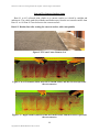
Figure C.26. Left Scanner (black area has no LiDAR return, and the red area represents the wet concrete) . 99
Figure C.27. Right Scanner (black area has no LiDAR return, and the red area represents the wet concrete)
........................................................................................................................................................................... 99
Figure C.28. Front Center Camera view ............................................................................................................... 100
Figure C.29. Left Scanner (black area has no LiDAR return, and the red area represents the wet concrete)100
Figure C.30. Right Scanner (black area has no LiDAR return, and the red area represents the wet concrete)
......................................................................................................................................................................... 100
Figure C.31. Front Right Camera view ................................................................................................................. 101
Figure C.32. Left Scanner (black area has no LiDAR return, and the red area represents the wet concrete)101
Figure C.33. Right Scanner (black area has no LiDAR return, and the red area represents the wet concrete)
......................................................................................................................................................................... 101
Figure C.34. Front Left Camera view .................................................................................................................... 102
Figure C.35. Left Scanner (black area has no LiDAR return, and the red area represents the wet concrete)102
Figure C.36. Right Scanner (black area has no LiDAR return, and the red area represents the wet concrete)
......................................................................................................................................................................... 102
Figure C.37. Front Center Camera view ............................................................................................................... 103
Figure C.38. Left Scanner (black area has no LiDAR return, and the red area represents the wet concrete)103
Figure C.39. Right Scanner (black area has no LiDAR return, and the red area represents the wet concrete)
......................................................................................................................................................................... 103
Figure E.1: Main LAS archive tool user interface ................................................................................................ 157
viii
Copyright 2015, AHMCT Research Center, UC Davis
Mobile Terrestrial Laser Scanning Workflow Development, Technical Support and Evaluation
LIST OF TABLES
Table 4.1 Caltrans MTLS deployment statistics ..................................................................................................... 16
Table 5.1. Registration target shape and size used in MTLS projects .................................................................. 27
Table 5.2. High reflectivity target materials for MTLS projects ........................................................................... 27
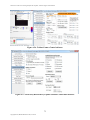
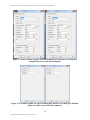
Table 6.1. Fields for photolog viewer database table “sessions” ............................................................................ 34
Table 6.2. Fields for photolog viewer database table “photolog” .......................................................................... 34
Table 6.3. DBF fields required for each set of MTLS images ................................................................................ 36
Table 7.1 Data rate of MTLS sensors ...................................................................................................................... 43
Table A.1. Scan line spacing vs. vehicle speed and scan rate ................................................................................. 56
Table A.2. Point spacing on a scan line at 50 meter range vs. scan and measurement rate ................................ 57
Table A.3. Point spacing on a scan line at 75 meter range vs. scan and measurement rate ................................ 57
Table A.4. Riegl VQ-450 laser scanner maximum range vs. measurement rate .................................................. 57
ix
Copyright 2015, AHMCT Research Center, UC Davis
Mobile Terrestrial Laser Scanning Workflow Development, Technical Support and Evaluation
CODE LISTINGS
Listing D.1: Code slideshow.js to be located in /var/www/slideshow2/js ............................................................ 106
Listing D.2: Code slideshow.php to be located in /var/www/slideshow2............................................................. 122
Listing D.3: Shell script to set up session database table (doSession.sh)............................................................. 131
Listing D.4: Shell script to populate photolog database table (doPopulate.sh) .................................................. 131
Listing D.5: Shell script to set Exchangeable Image File Format (EXIF) data fields in JPEG images
(doExif.sh) ....................................................................................................................................................... 131
Listing D.6: Shell script to scale back-center images (bcProcess.sh) using convert utility from imagemagick131
Listing D.7: Shell script to scale and crop back-down images (bdProcess.sh) using convert utility from
imagemagick ................................................................................................................................................... 132
Listing D.8: Shell script to scale and crop back-left images (blProcess.sh) using convert utility from
imagemagick ................................................................................................................................................... 132
Listing D.9: Shell script to scale and crop back-right images (brProcess.sh) using convert utility from
imagemagick ................................................................................................................................................... 132
Listing D.10: Shell script to scale front-center images (fcProcess.sh) using convert utility from imagemagick
......................................................................................................................................................................... 133
Listing D.11: Shell script to scale and crop front-left images (flProcess.sh) using convert utility from
imagemagick ................................................................................................................................................... 133
Listing D.12: Shell script to scale and crop front-right images (frProcess.sh) using convert utility from
imagemagick ................................................................................................................................................... 133
Listing D.13: Java utility to set up session database table (populateSession.java) ............................................ 134
Listing D.14: Java utility to populate photolog database table (Populate.java) ................................................. 136
Listing D.15: Perl utility to determine county, route, and postmile from latitude and longitude (setPostmile.pl)
......................................................................................................................................................................... 143
Listing D.16: Java utility to support setting Extensible Metadata Platform (XMP) Exchangeable Image File
Format (EXIF) data fields in JPEG images (XMPTag.java) ..................................................................... 145
Listing D.17: Java utility for setting Exchangeable Image File Format (EXIF) data fields in JPEG images
(ExifWriter.java) ............................................................................................................................................ 147
Listing E.1: LAS archive tool code ......................................................................................................................... 165
x
Copyright 2015, AHMCT Research Center, UC Davis
Mobile Terrestrial Laser Scanning Workflow Development, Technical Support and Evaluation
LIST OF ACRONYMS AND ABBREVIATIONS
Acronym
Definition
AC
AHMCT
AVI
BATA
CAD
Caltrans
CCD
CCH83
CCS83
CDRH
CHP
CORS
DBF
DC
DES
DHIPP
DMI
DOE
DOP
DOT
DRISI
DTM
ESC
EXIF
fps
FTP
GAMS
GB
GIS
GNSS
GPS
IEC
IMU
IP
IR
IT
JPEG
LAS
LCD
LED
LiDAR
LRS
LSIT
MAIT
MAP-21
MP
MPH
MTLS
NIR
Asphalt Concrete
Advanced Highway Maintenance and Construction Technology Research Center
Audio Video Interleave
Bay Area Transportation Authority
Computer-Aided Design
California Department of Transportation
Charge-Coupled Device
California Orthometric Heights of 1988
California Coordinate System of 1983
Center for Devices and Radiological Health
California Highway Patrol
Continuously Operating Reference Station
Database File
Direct Current
Division of Engineering Services
Caltrans Digital Highway Inventory Photography Program
Distance Measuring Instrument
Caltrans Division of Equipment
Dilution-of-Precision
Department of Transportation
Caltrans Division of Research, Innovation and System Information
Digital Terrain Model
Caltrans Equipment Service Center
Exchangeable Image File Format
frames per second
File Transfer Protocol
GPS Azimuth Measurement Subsystem
Gigabyte
Geographic Information System
Global Navigation Satellite System
Global Positioning System
International Electrotechnical Commission
Inertial Measurement Unit
Internet Protocol
Infrared
Information Technology
Joint Photographic Experts Group
Log ASCII Standard
Liquid-Crystal Display
Light-Emitting Diode
Light Detection and Ranging
Linear Reference System
Land Surveyor-in-Training
CHP Multidisciplinary Accident Investigation Teams
Moving Ahead for Progress in the 21st Century Act
Megapixel
Miles Per Hour
Mobile Terrestrial Laser Scanning
Near-Infrared
xi
Copyright 2015, AHMCT Research Center, UC Davis
Mobile Terrestrial Laser Scanning Workflow Development, Technical Support and Evaluation
Acronym
Definition
NOAA
ODBC
OLS
OoP
OTech
PB
PCC
PERT
PM
POS
QA/QC
RINEX
ROI
SOAP
SR
TAMP
TB
TLS
TSSS
UCD
UPS
USB
UTC
UTM
UV
VDC
XMP
National Oceanic and Atmospheric Administration
Open Database Connectivity
Caltrans Office of Land Surveys
Caltrans Office of Photogrammetry
California Office of Technology Services
Petabyte
Portland Cement Concrete
Program Evaluation Review Technique
Postmile
Position and Orientation System
Quality Assurance / Quality Control
Receiver Independent Exchange Format
Return on Investment
Simple Object Access Protocol
State Route
Transportation Asset Management Plan
Terabyte
Terrestrial Laser Scanning (fixed)
Total Station Survey System
University of California - Davis
Uninterruptible Power Supply
Universal Serial Bus
Coordinated Universal Time
Universal Transverse Mercator
Ultraviolet
Virtual Design and Construction
Extensible Metadata Platform
xii
Copyright 2015, AHMCT Research Center, UC Davis
Mobile Terrestrial Laser Scanning Workflow Development, Technical Support and Evaluation
ACKNOWLEDGMENTS
The authors thank the California Department of Transportation (Caltrans) for their support, in
particular Mark Turner, John Adam, Kevin Akin, John Gilmore, and Robert MacKenzie with the
Division of Right of Right of Way and Land Surveys, and Arvern Lofton with the Division of
Research, Innovation and System Information. The authors thank Headquarters and District 1, 2,
3, and 4 surveyors and managers: Nelson Aguilar, Jeremiah Bean, David Brubaker, Pat Crites,
Thomas Dale, Randy Haralson, James Harcharik, Matthew Herbert, John Lehti, Mike
McCalligan, Robert McMillan, Aaron Ott, Andrew Robertson, Richard Ray, Carlos Sablan, Eric
Vance, C. J. Vandegrift, Khin Voong, and Nick Zike for their valuable participation and
contributions. We also thank Larry Orcutt and his staff at the Caltrans Division of Equipment for
their active support on the MTLS vehicle integration. We also thank Tony Tavares and the
Division of Maintenance for their support of this research. The authors acknowledge the
dedicated efforts of the AHMCT team who have made this work possible.
xiii
Copyright 2015, AHMCT Research Center, UC Davis
Mobile Terrestrial Laser Scanning Workflow Development, Technical Support and Evaluation
CHAPTER 1:
INTRODUCTION
Problem
Mobile Terrestrial Laser Scanning (MTLS) can produce accurate and precise geospatial data
at or near highway speeds. Mobile laser scanners have been effectively used in pavement
condition surveys. Their transportation application, however, is broader and has the potential for
other California Department of Transportation (Caltrans) applications such as rapid project
delivery, structure clearance, preliminary investigation, asset management, project management,
as-built documentation, bridge rehabilitation, sight distance upgrades, reconstruction and repair
of sound walls, heaving pavement and AC leveling, culverts, railroad crossings, structures
damage assessments and replacements, lean operations in maintenance and reconstruction, and
enhanced safety [3,4]. MTLS systems have also proven to be a cost effective solution. Based on
previous Advanced Highway Maintenance and Construction Technology (AHMCT) research
recommendations, Caltrans completed the procurement of an MTLS system at the outset of this
research project. The primary motivation and use for MTLS within Caltrans is transportation
project delivery, with one related element being pavement elevation surveys. As part of this
research, and in conjunction with Caltrans pilot studies, it has been demonstrated that MTLS
does meet Caltrans’ requirements for pavement elevation surveys. The MTLS system also
provides a replacement for the Vangarde system. The purposes of the current project were to
research proper integration of MTLS into current Caltrans workflow and to develop best
practices in using MTLS for various Caltrans projects.
Caltrans began investigating possible investment in MTLS technology around 2009. It
developed an Information Technology (IT) Concept Paper entitle “Mobile Terrestrial Laser
Scanning – Mobile Laser Scanning for Lean and Rapid Highway Maintenance and Construction.
One essential goal was to replace the aging Vangarde system. Following this concept paper,
Caltrans and AHMCT initiated two complementary research projects. The first, “Application of
Mobile Laser Scanning for Lean and Rapid Highway Maintenance and Lean Construction,”
evaluated MTLS software packages, investigated means for accuracy improvements in MTLS,
and experimentally evaluated control target spacing needs vs. accuracy requirements. The second
project, “Mobile Terrestrial Laser Scanning Workflow Development, Technical Support and
Evaluation,” is this report’s project, and is intended to provide research and development support
for Caltrans deployment and use of MTLS in its survey operations. During this research period,
Caltrans also produced a Decision Document entitled “Mobile Terrestrial Laser Scanning
System,” which, in part, led to Caltrans’ acquisition of the MTLS system used in these two
research projects, and in regular Caltrans operations.
As part of the larger picture, Caltrans has been pursuing related efforts related to asset
management, upgrading their photolog collection, storage, and retrieval system, and in pavement
management systems which also include significant roadway imagery, as well as ground
penetrating radar. For example, Caltrans has developed an IT Concept Paper for photolog system
replacement, and has also performed an extensive internal survey related to Caltrans use of
photolog imagery. Caltrans is developing a statewide Transportation Asset Management Plan
(TAMP). All of these emerging or advancing efforts are increasing the amount of geospatial data
and imagery that Caltrans will need to deal with. In the past, each has been handled as a distinct
1
Copyright 2015, AHMCT Research Center, UC Davis
Mobile Terrestrial Laser Scanning Workflow Development, Technical Support and Evaluation
system. It would be very useful to have an integrated system that would link this data together
for accessing and viewing. At a minimum, it would be useful to have an integrated system for
accessing and viewing all geospatial images. Utah DOT’s UPlan initiative should serve as an
excellent model as Caltrans considers efforts in this area [1].
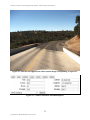
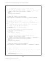
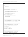
Figure 1.1. Caltrans Trimble MX8 MTLS vehicle at
San Francisco-Oakland Bay Bridge Toll Plaza.
2
Copyright 2015, AHMCT Research Center, UC Davis
Mobile Terrestrial Laser Scanning Workflow Development, Technical Support and Evaluation
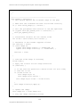
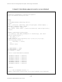
Figure 1.2. Caltrans MTLS system scan data at HWY 20 Yuba County.
Front Left Camera Image
Front Center Camera Image
Front Right Camera Image
Back Right Camera Image
Back Center Camera Image
Back Left Camera Image
Back Down Camera Image
Image collected at HWY580
at Altamont Pass
Figure 1.3. Caltrans MTLS system photo collection on HWY 580.
3
Copyright 2015, AHMCT Research Center, UC Davis
Mobile Terrestrial Laser Scanning Workflow Development, Technical Support and Evaluation
Background
Funding for an MTLS system became available due to a light winter snow storm season.
Caltrans procured a Trimble MX8 MTLS system. The objective of the research is to facilitate
effective deployment of the MTLS system in Northern California in conjunction with the
Caltrans Office of Land Surveys. AHMCT researchers were involved in the MTLS system
vehicle integration, data collection training, training material development, documentation on
best practices and workflow on MTLS data collection, utilization analysis, and MTLS impact
study.
Research Approach
The current work builds on AHMCT’s experience with Terrestrial Laser Scanning (TLS) and
MTLS [2,4].
The research work included:
Support for vehicle integration with the MTLS system and system testing
Identification of projects for field evaluation of the system and pilot study
Performing case studies and evaluating experimental results from the field trials
Develop best practices and workflow documentation
Develop training material and conduct training sessions
MTLS impact study.
Overview of Research Results
The results in this project final report include:
Report on system installation and usage instructions
Lessons learned from MTLS deployment and training
Report on best practices and workflow documentation work
Scanning wet concrete and asphalt pavement testing
Development of a photolog viewer.
4
Copyright 2015, AHMCT Research Center, UC Davis
Mobile Terrestrial Laser Scanning Workflow Development, Technical Support and Evaluation
CHAPTER 2:
VEHICLE INTEGRATION
Background
The procured MTLS system did not include the support vehicle necessary to provide power,
operator support, and mobility.
The support vehicle functional requirements are:
Support sensor pod (two laser scanners, IMU (Inertial Measurement Unit), GPS
(Global Positioning System) antennae, and seven cameras) mounted on the roof of the
vehicle.
Provide room and cooling for the equipment rack mounted inside the vehicle.
Provide sufficient power to the MTLS system during operation.
Provide space for the operator to control and monitor the MTLS system
Preserve vehicle basic performance despite the added weight on the roof,
aerodynamic drag, and change of vehicle center of gravity due to the sensor pod.
Other MTLS users have used large sport utility vehicles, full size trucks, and minivans to
house the MTLS system. Ideally, a new vehicle should be used to house the new MTLS system.
However, new vehicle procurement requires long lead time. In order to speed up the deployment,
Caltrans North Region Office of Surveys provided a Chevrolet Suburban from their fleet for
MTLS integration. Caltrans Division of Equipment (DOE) personnel performed all the necessary
vehicle modifications to support the Trimble MX8 integration. Trimble and California Surveying
and Drafting Supply (vendor) personnel installed the MX8 MTLS system with assistance from
Caltrans Equipment Service Center (ESC) personnel in the Sacramento ESC facility. The entire
process, including vehicle modifications and field testing, took approximately one week.
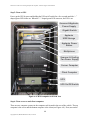
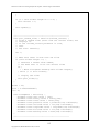
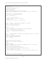
Trimble MX8 MTLS System Description
The Trimble MX8 is a commercial product of Trimble. The MX8 system consists of a sensor
pod mounted on the vehicle roof rack, Distance Measuring Indicator (DMI) mounted on the
driver side rear wheel, computer rack mounted at the vehicle rear, and monitors and accessories
mounted to the workstation as shown in Figures 2.1, 2.2, 2.3 and 2.4. A detailed description of
the Trimble MX8 system is available in the Caltrans Trimble MX8 Operation Manual in
Appendix A.
5
Copyright 2015, AHMCT Research Center, UC Davis
Mobile Terrestrial Laser Scanning Workflow Development, Technical Support and Evaluation
BD Camera
Pri. GNSSAntenna
Riegl VQ450
Laser Scanner
BC Camera
BR Camera
BL Camera
GAMS GNSSAntenna
DMI
Figure 2.1. Caltrans Trimble MX8 MTLS system sensor pod and DMI
Pri. GNSSAntenna
FL Camera
FC Camera
Riegl VQ450
Laser Scanner
FR Camera
Figure 2.2. Caltrans Trimble MX8 MTLS system sensor pod (front view)
6
Copyright 2015, AHMCT Research Center, UC Davis
Mobile Terrestrial Laser Scanning Workflow Development, Technical Support and Evaluation
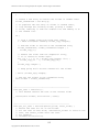
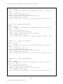
Figure 2.3. MX8 user interface (dual monitors, keyboard, and trackball) mounted next to
the driver
Figure 2.4. MX8 computer rack mounted at the vehicle rear
7
Copyright 2015, AHMCT Research Center, UC Davis
Mobile Terrestrial Laser Scanning Workflow Development, Technical Support and Evaluation
Vehicle Integration
The Trimble MX8 MTLS system was installed on a Chevrolet Suburban with modifications
in several areas to support the MX8 system:
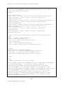
1. Auxiliary battery and battery isolators with circuit breakers were added to provide
scanner electrical power. The battery isolators prevent the MX8 from over-draining the
main battery when the engine is not running.
Figure 2.5. Extra battery and battery isolators with circuit breakers added in the engine
compartment
2. The factory alternator was replaced with a 250 amp alternator with a smaller pulley wheel
to increase current/power output at engine idle.
3. An automatic engine idle adjusting system was added to maintain voltage output at
engine idle by increasing the engine idling speed. Typically, the engine idle speed is
about 800 to 1,200 engine rpm when the MX8 is running with the vehicle in Park and
brake pedal not depressed. Sufficient power is provide to the MX8 system. However,
when the brake pedal is applied, the vehicle engine controller overrides the idle adjusting
system and lowers the engine idle speed to normal engine idle speed. In this situation, the
MX8 system relies on the batteries to supplement power to address reduced power output
from the alternator. Typical MX8 current consumption ranges from 60 to 80 amps
depending on the MX8 equipment electrical load and supply voltage.
4. Four Thule roof racks were added to mount the MX8 sensor pod rack.
8
Copyright 2015, AHMCT Research Center, UC Davis
Mobile Terrestrial Laser Scanning Workflow Development, Technical Support and Evaluation
5. The front passenger seat was replaced with a custom table platform for mounting the pure
sine wave inverter, dual liquid-crystal display (LCD) monitors, keyboard and trackball
mouse as shown in Figures 2.3 and 2.6. The table platform is integrated to the power seat
mount so that the computer table can be moved up and down as well as back and forth.
Figure 2.6. Front passenger seat modification
6. A diamond plate built up floor was installed behind the rear seats to allow for mounting
the MX8 computer rack as shown in Figure 2.4.
7. A custom plastic shield was mounted on the driver’s side rear door window to allow the
sensor pod cable to pass through as shown in Figure 2.1.
System Calibration
System calibration, which includes DMI calibration and laser alignment, is required after the
MTLS system installation. DMI calibration, calibrated wheel rotation to the distance travel,
should be performed after tire change or rotation. Detailed DMI calibration procedures are
provided in the Caltrans Trimble MX8 Operation Manual in Appendix A. Laser alignment
calibration data collection is performed after DMI calibration and as part of data collection
training. Detailed laser alignment calibration is provided in the Trimble MX8 manual. Laser
alignment is required whenever the laser(s) sensor is removed from the sensor pod.
Lessons Learned
Over nineteen months of operation, the system was fairly reliable. There were a few
problems encountered.
9
Copyright 2015, AHMCT Research Center, UC Davis
Mobile Terrestrial Laser Scanning Workflow Development, Technical Support and Evaluation
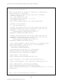
1. Original factory roof rack failure: The aerodynamic load from the sensor pod
yielded large pull-out forces on the roof rack mounts at the front of the vehicle. These
large pull-out forces resulted in cracks developing at the roof rack mount points as
shown in Figure 2.7. The original manufacturer’s roof rack was replaced with a
custom roof rack, as shown in Figure 2.8, made by the mechanics at the ESC. The
custom roof rack is attached the vehicle roof by sandwiching the thin sheet metal
vehicle roof between two thick steel plates, thus reducing the likelihood of tear-out.
Figure 2.7. Cracks developed at the front roof rack mounts
10
Copyright 2015, AHMCT Research Center, UC Davis
Mobile Terrestrial Laser Scanning Workflow Development, Technical Support and Evaluation
Figure 2.8. Custom roof rack made by mechanics at ESC
2. Alternator upgrade: The original alternator was upgraded to a 250 amp alternator
because the factory installed alternator does not provide adequate power to the MX8
system at engine idle.
3. Lens covers: Lens covers (43 mm metal screw-in lens caps and 43 mm snap-on lens
caps) were added to cover all seven camera lenses to keep the lenses clean from bugs
11
Copyright 2015, AHMCT Research Center, UC Davis
Mobile Terrestrial Laser Scanning Workflow Development, Technical Support and Evaluation
when transporting to and from the project site. The lens covers are taken off before
data collection. The lens covers reduce the need for cleaning the camera lenses before
data collection.
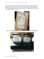
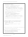
4. Laser sensors replacement: After several months of use, liquid droplets were found
on the inside of both left and right laser scanner optical windows as shown in
Figure 2.9. Bearing seal failure may be the cause of the oil droplet deposits. Both
laser scanners were replaced under manufacturer warranty.
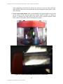
Figure 2.9. Liquid droplet found inside the laser scanner head
12
Copyright 2015, AHMCT Research Center, UC Davis
Mobile Terrestrial Laser Scanning Workflow Development, Technical Support and Evaluation
5. Cooling fan failure: A cooling fan inside the sensor pod was replaced under
warranty.
6. Display mount replacement: The original monitor mounts, shown in Figure 2.3,
became loose due to the vehicle vibration. They were replaced with an all-metal dualLCD monitor mount as shown in Figure 2.6.
7. Software Issue: Part of the Trimble software Windows Registry related to photo
logging was corrupted. The Window Registry was promptly repaired by Trimble
technical support.
13
Copyright 2015, AHMCT Research Center, UC Davis
Mobile Terrestrial Laser Scanning Workflow Development, Technical Support and Evaluation
CHAPTER 3:
TRAINING
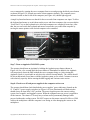
Background
After the installation of the MX8 system, Trimble personnel conducted data collection
training and in-office data post-processing training. The data collection training session was
recorded on video. One surveyor from each northern California district (1, 2, 3 & 4) participated
in the training. Due to the limited seating available in the MTLS vehicle, only two surveyors
could be trained at a time for data collection. Since then, the four trained surveyors have trained
other surveyors in their district to operate the MTLS system for data collection as well as data
post-processing.
Figure 3.1. MTLS field data collection training at HWY20 Yuba County, CA. (Performing
5-minute static GNSS/IMU data collection at the end of the project data collection)
The video recordings of the data collection training have been edited by Caltrans personnel
into a series of condensed training videos for future personnel training. In addition, the Caltrans
Trimble MX8 Operation Manual (Appendix A herein) was written for data collection training.
The Caltrans Trimble MX8 Operation Manual provides a concise procedure and information for
system startup, software setup for data collection, and shutdown procedures. A detailed Trimble
MX8 user manual is provided by Trimble. A Caltrans MX8 Vehicle Checklist was also created
to ensure all necessary steps are followed and assure that MTLS data are collected properly and
consistently.
Recommendations
MTLS data collection and post-processing is a highly perishable skill if not used. Computer
workstation and software installation and setup should be completed before training. In addition,
MTLS projects should be made ready for MTLS data collection and post-processing after the
MTLS training. Performing MTLS projects immediately after training provides operators with
practical experience to reinforce and engrain their training and learning into long-term memory.
14
Copyright 2015, AHMCT Research Center, UC Davis
Mobile Terrestrial Laser Scanning Workflow Development, Technical Support and Evaluation
Based on the lessons learned from the northern California deployment, the MTLS Deployment
Plan for central and southern California districts, shown in Figure 3.2, was developed.
MTLS Deployment Plan in Central and Southern California Districts
Run pilot projects
@ participating districts
Coordinate with Trimble for
on-site training
Procure software licenses
Applanix PosPAC MMS - Status: 2@Caltrans,
1@UCD, more needed.
Trimble Trident Imaging Hub LM0033-00-00 Status: 5@Caltrans.
PolyWorks - Status: 1@UCD, 5@Caltrans.
TopoDOT - Status: 1000hr@Caltrans.
Virtual Geomatics - Status: 1@UCD, 1@D4.
Support Document: IT software approve list - Status:
completed.
Procure IT workstations & external drives
Deployment of MX8
in central and
southern California
districts
Working with Trimble to schedule
for data post-processing training Status: not complete.
Obtain PosPAC MMS & Trimble
Trident temporary licenses Status: not complete.
Install software on workstation
@ participating districts
Support Document: None
Install software and make
available for MTLS personnel in
southern & central districts Status: in progress.
MX8 post-processing
personnel training
Support Document: None
IT hardware for central and southern district offices
for post-processing.
Workstations - Status: completed.
Portable external hard drives - Status: completed.
Support Document: IT Justification - Status:
completed (used northern districts’ approved
justification).
Workstation specification - Status: update needed.
Portable hard drive specification - Status; update
needed.
c
Pilot projects selection
@ participating districts
Working with the district survey
supervisors to select pilot projects
for MTLS - Status: in progress.
Training MX8 post-processing
personnel in southern & central
districts - Status: not complete.
Support Document: Training
manual & video - Status: not
complete.
MX8 driver & operator
personnel training
Training MX8 drivers & operators
in southern & central districts Status: not complete.
Support Document: None
Support Document: Training
manual & video - Status:
completed, update as needed.
Personnel selection for each participating district
Working with the district survey supervisors to select
personnel for MTLS training - Status: not complete.
Support Document:
MTLS driver personnel requirements / job description
- Status: update needed.
MTLS operator personnel requirements / job
description - Status: update needed.
MTLS data post-processing personnel requirement /
job description - Status: update needed.
Working with the district surveyors to
run MTLS pilot projects:
Data Collection - Status: not complete;
Post-processing - Status: not complete;
Feature Extraction - Status: not
complete.
Support Document: None
Document lessons learned
Working with the district surveyors to
run MTLS pilot projects:
Data Collection - Status: not complete;
Post-processing - Status: not complete;
Feature Extraction - Status: not
complete.
Support Document: lessons learned,
revised software and hardware
requirements
Run regular projects
@ participating districts
District surveyors to run MTLS projects
by themselves:
Data Collection - Status: not complete;
Post-processing - Status: not complete;
Feature Extraction - Status: not
complete.
Support Document: None
Coordinate MX8 schedule
Revise MTLS specifications
Working with northern districts to
coordinate MX8 work schedule
Revise MTLS specification for 2nd unit
procurement - Status: not complete.
Develop justification for 2nd MTLS unit
procurement if applicable - Status: not
complete.
Support Document: MX8 calendar
setup - Status: completed.
Refine feature extraction
workflow
Working with district surveyors to
revise training materials - Status:
not complete.
Support Document: Revised
training materials - Status: not
complete.
Develop data archiving best
practices
Working with the district
surveyors to revise training
materials - Status: not complete.
Support Document: Revised
training materials - Status:
completed.
Support Document: Revised MTLS
specifications - Status: not complete;
2nd MTLS justification - Status: not
complete.
Figure 3.2. Caltrans MTLS deployment plan in central and southern California districts
15
Copyright 2015, AHMCT Research Center, UC Davis
Mobile Terrestrial Laser Scanning Workflow Development, Technical Support and Evaluation
CHAPTER 4:
CALTRANS MTLS DEPLOYMENT STATUS AND USAGE
Caltrans MTLS Usage
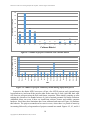
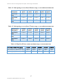
Caltrans MTLS project data statistics, shown in Table 4.1, Figure 4.2, 4.3, and 4.4, were
collected from November 2012 to May 2014 (19 months). The Caltrans MTLS vehicle was
actively deployed for eighteen months for data collection during this period. The vehicle/system
was offline for one month repairing the vehicle roof rack and replacing the two laser scanners.
Ninety MTLS projects were scanned in eight different Caltrans districts. The majority of the
MTLS projects were to generate pavement Digital Terrain Model (DTM). MTLS projects
included rural and urban multi-lane divided highways, rural undivided highways, bridges, and
tunnels. Two MTLS projects’ data were used in AHMCT research projects for the Caltrans
Division of Maintenance. Northern California districts (1, 2, 3, & 4) are the primary users. They
have performed work for other Caltrans districts, including 6, 9, 10, and 11. The Caltrans Office
of Photogrammetry (OoP) in Headquarters has been performing feature extraction for some of
the data collected by the MTLS system.
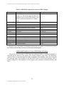
Table 4.1 Caltrans MTLS deployment statistics
MTLS Project statistics
Total number of MTLS projects scanned
Total number of Caltrans districts deployed
Average number of projects per month
Average number of centerline miles per project
Average number of miles vehicle travel for every
centerline miles scanned
Number of MTLS projects used in research projects for
Caltrans Division of Maintenance
Number of MAIT projects
Number of bridge clearance projects
Number of projects for outdoor advertisement
16
Copyright 2015, AHMCT Research Center, UC Davis
90 projects
8 districts
5 projects/month
5 miles/project
52 miles/centerline miles scanned
2 projects
3
8
8
Mobile Terrestrial Laser Scanning Workflow Development, Technical Support and Evaluation
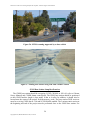
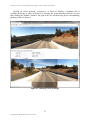
Figure 4.1. MTLS deployment at HWY 580 in District 4 (Urban multi-lane highway)
240
229.25
220
Total Scanned Centerline Miles
200
180
160
140
120
100
80
60
69.3
51.3
33.7
40
20
0
7.6
15
14
0
5
0
0
0
1
2
3
4
5
6
7
Caltrans District
8
9
10
11
Figure 4.2. Number of highway miles scanned in each Caltrans district
17
Copyright 2015, AHMCT Research Center, UC Davis
12
Mobile Terrestrial Laser Scanning Workflow Development, Technical Support and Evaluation
39
40
Total Number of Projects
35
30
25
20
15
17
13
12
10
5
0
3
2
1
0
0
7
8
1
0
0
1
2
3
4
5
6
9
10
11
12
Caltrans District
16
14
12
10
8
6
4
2
May-14
Apr-14
Mar-14
Feb-14
Jan-14
Dec-13
Nov-13
Oct-13
Sep-13
Aug-13
Jul-13
Jun-13
May-13
Apr-13
Mar-13
Feb-13
Jan-13
Dec-12
0
Nov-12
Number of Scanned Projects
Figure 4.3. Number of projects scanned in each Caltrans district
Time
Figure 4.4. Number of projects scanned by month during deployment period
In practice, the district MTLS surveyors will get a few MTLS projects ready (ground target
layout and survey) and scan all the projects either on the same day or week. After that, their work
will focus on post-processing the data, and feature extraction. When initially ramping up after
training, this can take a few months because of a lack of trained personnel for feature extraction.
Additional delays can occur if there are insufficient software licenses and suitable computer
hardware. Since then, these limitations have been addressed and removed. Figure 4.4 illustrates
this behavior. The projects scanned tend to come in waves, where there is a period of inactivity
in scanning followed by a large number of projects scanned in a month. Figures 4.2, 4.3, and 4.4
18
Copyright 2015, AHMCT Research Center, UC Davis
Mobile Terrestrial Laser Scanning Workflow Development, Technical Support and Evaluation
showed that the MTLS system was well utilized. However, there is room to increase the system
utilization for more MTLS projects. The current limit on carrying out MTLS projects is the lack
of trained personnel for data collection, data post-processing, and feature extraction. Feature
extraction is comparatively the most time-consuming. Increasing the number of trained personnel
will be the key to increase MTLS system utilization and the return on investment (ROI). Thus,
conducting training for central and southern California district surveyors to perform MTLS
projects is a logical next step. MTLS has significantly reduced lead time and cost as well as
improving worker safety.
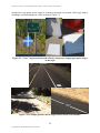
Figure 4.5. Point cloud collected from MTLS system
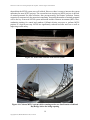
Figure 4.6. Caltrans MTLS system vehicle scanning on the new San Francisco-Oakland
Bay Bridge before the bridge opening
19
Copyright 2015, AHMCT Research Center, UC Davis
Mobile Terrestrial Laser Scanning Workflow Development, Technical Support and Evaluation
Figure 4.7. Caltrans MTLS system vehicle on the new San Francisco-Oakland Bay Bridge
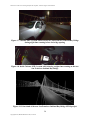
during night time scanning before the bridge opening
Figure 4.8. Inside Caltrans MTLS system vehicle during a night time scanning on the new
San Francisco-Oakland Bay Bridge
Figure 4.9. Point cloud of the new San Francisco-Oakland Bay Bridge MTLS project
20
Copyright 2015, AHMCT Research Center, UC Davis
Mobile Terrestrial Laser Scanning Workflow Development, Technical Support and Evaluation
CHAPTER 5:
BEST PRACTICES AND WORKFLOW
The focus of the current project is establishment and documentation of the MTLS data
collection workflow. A detailed MTLS data collection workflow using Caltrans MTLS system is
provided in Appendix A, the Caltrans Trimble MX8 Operation Manual. A high-level overview
of the MTLS system data flow diagram is presented in Figure 5.1. After the data collection and
transfer from the MTLS vehicle computers, the GNSS/IMU data is first post-processed with the
local base station(s) and/or Continuously Operating Reference Station (CORS) stations in the
vicinity of the project site using Applanix POSPac software. The best estimated vehicle
trajectory data, resulting from the GNSS/IMU post-processing, is then used to update the
Trimble .GPS files and Log ASCII Standard (LAS) Light Detection and Ranging (LiDAR) files
using Trimble Trident software. Then, Trident is used to first “Colorize” the point cloud with the
camera images. After the point cloud is registered to the ground control targets using Trident,
feature extraction for the final deliverable can begin using either Trident or other point cloud
software with LAS data exported from Trident.
Raw data collected from MTLS and GNSS base station
GNSS
Base
Data
(RINEX)
Applanix
GNSS/
IMU/DMI
Data
Trimble MX8 Data
Video (AVI) &
LiDAR (LAS)
GPS
files
TeraCopy (Optional) for file transfer ($)
Applanix
POSPac MMS
GNSS/IMU
Post-processing
Alternate Point Cloud
Adjustment Method
Microsoft
Access
Unadjusted
Georeferenced
Point Cloud
(LAS 1.2)
Trident
Software
Suite
Best Position
& Orientation
Estimate
($$$$$)
Virtual
Geomatics
Suite
QA/QC
Report
($$$)
($$$$)
Control
Adjusted
Point Cloud
(LAS 1.2)
Geoferenced
Photo Images
(*.jpg)
LASzip
(Free)
Trimble
RealWorks
Survey
LAStools
Point Cloud Feature Extraction Software
Cloud
Compare
Terra
Model
Suite
(Free)
($$$)
TopoDOT
Cyclone
($$)
($$)
Trident
Software
Suite
PolyWorks
($)
($$$$$)
($$$$)
Lane Line, Curb
Line, Road Sign,
GIS, etc.
Photolog, Caltrans GIS
& Caltrans Earth
Virtual
Geomatics
Suite
Bridge
Clearance
Classified
Point Cloud
(LAS)
Compressed
Point Cloud
(LAZ)
iLiDAR
(LAS)
Traffic Ops /
Bridge Maintenance
Data Archive
(CAD Model, Photo, Point Cloud)
Point Cloud Animation Software
Animation
Movies
Bentley
Pointools
Cyclone
Autodesk Autodesk
Navisworks 3DS Max
VDC Software
Autodesk
Navisworks
Autodesk
Revit
Free Point Cloud Visualization Software
Cloud
Compare
Cyclone
Viewer
Bentley
Pointools
Viewer
Figure 5.1. MTLS data post processing data flow diagram
21
Copyright 2015, AHMCT Research Center, UC Davis
AutoCAD
ReCap
UCD
LiDAR
Viewer
Mobile Terrestrial Laser Scanning Workflow Development, Technical Support and Evaluation
The procurement, testing, and evaluation of feature extraction software were initiated before
this project. Because of the complexity and diversity of deliverables and feature extraction, the
feature extraction workflow has not been finalized. Currently, a few software packages are being
used for feature extraction. Each software package excels in a few specific feature extractions or
in creating certain deliverables. Users often have to use a few software packages to complete the
entire deliverable data set required by the customers. For example, Cyclone is often used to
create point cloud fly-through movies and has an excellent point cloud visualization engine.
PolyWorks and Virtual Geomatics are used for lane line and edge line extraction because of their
reliable semi-automated tools for lane line and edge detection. A TopoDOT license was recently
acquired, and TopoDOT is currently being evaluated. The future goals are refining the feature
extraction workflow as well as selecting a reduced set of software needed to obtain deliverables
required by customers from the point cloud data.
The detailed workflow for creating point cloud fly-through movies using Cyclone was
presented by Mr. Hovig Devejian of Precision Civil Engineering, Inc. of Fresno, CA at the Leica
HDS
Conference
in
2009.
His
presentation
can
be
found
at:
http://hardhat.ahmct.ucdavis.edu/mediawiki/images/1/1b/Precision_Civil_Engineering.pdf. High
resolution movies should be made first, and lower resolution movies may be created by down
sampling the high resolution version.
To improve lane line extraction tool reliability in the current version of PolyWorks, the point
cloud intensity values from the Trident export may have to be rescaled using LAStools before
importing into PolyWorks. The intensity output values from the laser scanners do not distribute
to occupy the full intensity value range as shown in Figure 5.2. As a result, there is very little
contrast in intensity values between pavement and the lane stripes as shown in Figure 5.4.
Rescaling point cloud intensity values to occupy the full intensity value range improves the
contrast as well as the reliability of lane line extraction by PolyWorks. Other point cloud
software, such as Cyclone, has built-in functionality to adjust the contrast for better visualization
without the need for intensity rescaling pre-processing.
Figure 5.2. Point cloud intensity value distribution before rescaling
Figure 5.3. Point cloud intensity value distribution after rescaling
22
Copyright 2015, AHMCT Research Center, UC Davis
Mobile Terrestrial Laser Scanning Workflow Development, Technical Support and Evaluation
Figure 5.4. Point cloud before intensity value rescaling
Figure 5.5. Point cloud after intensity value rescaling
Rolling Lane Closure Best Practices
A rolling highway closure / traffic break using California Highway Patrol (CHP) and/or
shadow vehicle (See Figures 5.6 and 5.7) helps reduce data artifacts in post-processing. It also
mitigates shadows (voids in scan data points) created by large trucks and buses, and reduces data
post-processing time. The CHP is very effective in providing urban multi-lane rolling closure in
a typical divided highway as shown in Figure 5.2. Caltrans maintenance shadow vehicles have
also been used to provide rolling closure by some districts, providing positive results.
23
Copyright 2015, AHMCT Research Center, UC Davis
Mobile Terrestrial Laser Scanning Workflow Development, Technical Support and Evaluation
Figure 5.6. MTLS scanning supported by a chase vehicle
Figure 5.7. Rolling lane closure using CHP and a shadow vehicle
GNSS Base Station Setup Best Practices
The GNSS base station should be occupying CCS83 (2010.00 or 2011.00, refer to Caltrans
Survey Manual) and COH88 datum control point. The GNSS base station should be positioned
so that GNSS baseline length is kept under 10 km or 6 miles. In addition, it should also be
located near the center of the project for high-accuracy work. The base station GNSS receivers
must be set to log GNSS data at 1 Hz and be GLONASS-enabled. The 5-minute static session at
the beginning and end of the project must be performed close to the GNSS base station. For
24
Copyright 2015, AHMCT Research Center, UC Davis
Mobile Terrestrial Laser Scanning Workflow Development, Technical Support and Evaluation
critical projects in which rescanning the area is difficult, two GNSS base stations are highly
recommended.
Figure 5.8. Typical GNSS base station setup over local control at the project site
Geo-referencing and Registration Ground Targets
Ground geo-referencing and registration targets are used for registration and quality
assurance / quality control (QA/QC). Various target shapes and target materials were used in
different projects. Typical target spacing for projects is about 500 ft or ~0.1 miles. Some districts
employed Caltrans Maintenance personnel to lay down the targets; some districts relied on
surveyors to lay down targets. Using Caltrans Maintenance to lay down targets can reduce the
time because Caltrans Maintenance has a large well-trained labor force and equipment for
performing work at the roadside. On the other hand, some districts prefer laying down targets
and surveying the targets at the same time. It can be more efficient for Surveys to place targets,
particularly when using thermoplastic material.
Target Shape
Four different target shapes were used in various projects: chevron, square, rectangle, and
cross, as shown in Figures 5.9 and 5.10. The target size must be sufficiently large to collect
25
Copyright 2015, AHMCT Research Center, UC Davis
Mobile Terrestrial Laser Scanning Workflow Development, Technical Support and Evaluation
enough laser scan points on the target to accurately determine its location. Each target shape’s
advantages and disadvantages are listed in detail in Table 5.1.
Figure 5.9. “Cross” target on the left and reflective temporary striping tape square target
on the right
Figure 5.10. Example ground control targets located on the road shoulder
26
Copyright 2015, AHMCT Research Center, UC Davis
Mobile Terrestrial Laser Scanning Workflow Development, Technical Support and Evaluation
Table 5.1. Registration target shape and size used in MTLS projects
Target Shape
Square
Size
Pro
12”x 12” or Auto detection works well
24” x 24”
8”x18”
Auto detection works well; works
well in narrow hard shoulder
two 4”x18” Easy manual target extraction;
strip
target point well defined
18”x18”
Used in aerial targets
Rectangle
Chevron
Cross
Con
Wide shoulder required
Less points per target
Manual target extraction
required
Doesn’t work well with
either manual or automatic
extraction
Chevron targets are well-suited for manual target extraction; the surveyed point on the target
is comparatively easily to visually identify and extract manually. However, manual target
extraction is very time consuming and labor intensive work. On the other hand, square or
rectangular targets work well with built-in auto-extraction techniques in Trident software. Cross
targets are difficult to extract automatically or manually. Cross targets are not being used in
recent projects. Caltrans surveyors experienced the best outcome from square and rectangular
targets in recent projects using the Trident software automatic target extraction routine.
Target material
Targets must have high reflectivity to foster identification and extraction from the point
cloud. Three different high-reflectivity marking materials were used for target marking: white
striping paint with glass beads, reflective tape, and thermoplastic marking material used in lane
stripes. Templates are used for marking the target’s center. Generally, reflective tape targets are
used in specific case where the stakeholders prefer that all target marking be removed after
MTLS survey. For example, reflective tape targets were used in the new San Francisco-Oakland
Bay Bridge MTLS project where the customer (Bay Area Transportation Authority, BATA) did
not want any paint marking left behind after the survey.
Table 5.2. High reflectivity target materials for MTLS projects
Target Shape
Thermoplastic
marking for
lane stripe
Paint with
glass beads
Reflective
tape
Size
4”x36”
4”x18” with
cutting
Any size
Various tape
width, 4”, 6”
or 12”
Pro
Semi-permanent, high
reflectivity, long life
Low material cost, high
reflectivity
Easy to remove, adhere to
pavement, ~4 to 6 month life,
suitable for temporary target
on scenic highways or
structures
27
Copyright 2015, AHMCT Research Center, UC Davis
Con
Difficult to remove, limited
size and shape selection,
higher cost
Template required, higher
labor cost
Not suitable on traveled
way, short life.
Mobile Terrestrial Laser Scanning Workflow Development, Technical Support and Evaluation
Four different reflective tapes were tested for reflectivity on the road surface at various
ranges. All reflective tape performed well in close range. However, some tape’s reflectivity
drops more as the distance to the scanner increases. Figure 5.11 shows the reflectivity of various
reflective tapes. Red points are laser return from the black asphalt surface, and blue and green
points are from the return on the reflective tapes. The darker blue points represent higher
reflectivity, and green/yellow point represent lower reflectivity. While both 3M Scotchlite
reflective sheeting and Avery Dennison are gray, they have higher reflectivity than the white
reflective traction tape with glass beads. In addition, they adhere better to both asphalt and
concrete surfaces. The 6” wide 3M Scotchlite reflective sheeting was used in the new Bay Bridge
projects. The 4” wide Avery Dennison tape was employed in a research project for target
optimization.
Figure 5.11. Reflectivity measurement of various reflective tape (on the right, blue is more
reflective) and photo of various reflective tape (on the left, 6” wide 3M Scotchlite reflective
sheeting on top left, 4” wide Avery Dennison reflective tape second from top, 4” wide
reflective traction tape from McMaster second from bottom left, reflective traction tape
from a MTLS services provider on the bottom left).
Figure 5.12. Dust and dirt accumulate on the square reflective tape target (on the left) and
sweeping off dirt off target (on the right) before scanning
28
Copyright 2015, AHMCT Research Center, UC Davis
Mobile Terrestrial Laser Scanning Workflow Development, Technical Support and Evaluation
Data Archive Recommendations
The following files or directories should be archived at the end of projects
1. The MTLS data, including the Applanix POSPac directory and all files and folders in the
Trimble Trident folders (Access database, .LAS, .GPS, and .AVI files) should be archived.
2. Exported LAS files (version 1.1, 1.2, or 1.4), with folder name or readme.txt to indicate map
projects, geoid model used. (LAS 1.4 recently was made available with more information,
LAS files may be compressed using LASzip before archiving. A developed Python wrapper
with user-friendly graphic user interface may be used. Detail shown in Appendix E.).
3. Exported lens rectified JPG with DAT, TXT, SHP and TopoDOT options checked (JPG
image time, location, and orientation information are stored in SHP, DAT, TXT, and
TopoDOT survey files). All data field export options under “Fields” should be checked
before exporting the JPG files.
Figure 5.13. Trident Image Converter export options recommendations (DAT, TXT, SHP,
TopoDOT options checked)
4. Any project deliverable files.
5. Optional: Cyclone, PolyWorks, TopoDOT, RealWorks (etc.) files from LAS or TXT import.
29
Copyright 2015, AHMCT Research Center, UC Davis
Mobile Terrestrial Laser Scanning Workflow Development, Technical Support and Evaluation
CHAPTER 6:
PHOTOLOG VIEWER
Overview
With its imaging capabilities, it is possible to use the MTLS system to provide photolog
capabilities for scanned areas. To investigate the technical feasibility and requirements for using
MTLS to provide photologs, AHMCT developed utilities and a web-based viewer prototype for
photologs. This system is currently available for Caltrans use and evaluation. As of this writing,
19 data sets have been converted from raw MTLS data (imagery, location, etc.) into viewable
photologs. This chapter provides the details of the viewer prototype, the input data requirements,
and the utilities and workflows used to perform the conversion. Appendix D provides code
listings for viewer code and the shell scripts and utilities used in the conversion from MTLS data
to photolog.
Photolog Viewer Prototype
Photolog Viewer User Perspective
From the perspective of the end user, the photolog viewer prototype consists of a web page,
as shown in Figure 6.1. Here, the top tiled images are the front left, front center, and front right
camera views. The bottom tiled images are the back right, back center, and back left camera
views. The back down camera view is at the very bottom. Each of the individual scaled and
cropped images is a link to the original full-size, uncropped image. For example, clicking on the
front center image in the photolog viewer brings up a separate web browser window showing the
full-size, uncropped front center camera image shown in Figure 6.2. All images are scaled. All
but the two center images are cropped.
The photolog controls and status information are located in the middle, between the front and
back camera views. Figure 6.3 provides a close-up of the controls and information panel. The
control buttons are intended to be self-explanatory but will be described briefly here. The “start”
button begins playing the photolog images in the forward direction at a default speed. The “stop”
button pauses the photolog playback. The “rewind” button begins playing the photolog images in
the reverse direction at a default speed. The “<prev” button advances the photolog image one
step in the reverse direction. The “next>” button advances the photolog image one step in the
forward direction. The “slower” button slows down the photolog playback one speed step. The
“faster” button speeds up the photolog playback one speed step. There are internal settings for
minimum and maximum playback speeds. Once these are reached, the corresponding speed
change button will have no further effect.
The status information is located below these control buttons. The information again should
be self-explanatory. The “Year” is the year that the MTLS scan was performed. The “County”,
“Route”, and “Postmile” is the postmile Linear Reference System (LRS) information
corresponding to the current image. The “Latitude”, “Longitude”, and “Altitude” are the GPS
location for the current image. The “Heading” is the vehicle compass heading (from GNSS and
IMU) for the current image.
30
Copyright 2015, AHMCT Research Center, UC Davis
Mobile Terrestrial Laser Scanning Workflow Development, Technical Support and Evaluation
Clicking on “Select photolog” in Figure 6.1 or Figure 6.3 displays a dropdown list of
available photologs, as shown in Figure 6.4. Selecting one of the photologs from the list, and
then clicking the “Submit” button to the right of the list will then bring up the corresponding
photolog in the web browser.
Figure 6.1. Photolog viewer prototype
31
Copyright 2015, AHMCT Research Center, UC Davis
Mobile Terrestrial Laser Scanning Workflow Development, Technical Support and Evaluation
Figure 6.2. Full-size uncropped front center camera image corresponding to Figure 6.1
Figure 6.3. Controls and status information panel
32
Copyright 2015, AHMCT Research Center, UC Davis
Mobile Terrestrial Laser Scanning Workflow Development, Technical Support and Evaluation
Figure 6.4. Photolog select dropdown list
This represents the extent, features, and use of the photolog viewer from the user perspective.
Photolog Viewer Internal Details
While the photolog viewer is intentionally quite simple from the user perspective, the internal
details are much more involved. These details are documented here, both for Caltrans’
information and as an internal record for AHMCT researchers. Code is provided in Appendix D.
The server must be running the apache web server, configured to support PHP and
JavaScript web scripting languages. The server must also be running the mysql database server.
The photolog server system has only been tested on a server running Linux; however, it should
be possible to run the photolog viewer on other operating systems, as the noted prerequisites are
available.
The photolog viewer is based on a JavaScript slideshow viewer developed by Patrick
Fitzgerald, found at:
http://slideshow.barelyfitz.com/
33
Copyright 2015, AHMCT Research Center, UC Davis
Mobile Terrestrial Laser Scanning Workflow Development, Technical Support and Evaluation
The slideshow viewer was extended to allow multiple simultaneous images. The JavaScript code
for the slideshow viewer (slideshow.js) is provided in Appendix D.
The actual photolog viewer web page is dynamically generated by PHP code. The listing for
the code (slideshow.php) is provided in Appendix D. This PHP code is driven by a MySQL
database. Generation of this database is described in a subsequent section. This database, named
“piwigo,” has two tables relevant to the photolog viewer. The first table, “sessions,” is used to
select photolog sessions. Its fields are shown in Table 6.1. The second table, “photolog,”
contains the detailed photolog information for each image. Its fields are shown in Table 6.2.
Table 6.1. Fields for photolog viewer database table “sessions”
Field
Id
sessionName
sessionDescription
Description
ID number of the session
Searchable description of the session including the scan vehicle ID,
scan location, route number, date, and scan number
Text description of the session, including scan location, route number,
date, and scan number. Appears in photolog selection dropdown list
Table 6.2. Fields for photolog viewer database table “photolog”
Field
Idx
sessionID
direction
latitude
longitude
altitude
postmile
county
route
image
dist
gpsTime
gpsDate
gpsDateTime
gpsDist
heading
roll
pitch
hdop
velocity
Description
Index number to keep track of the order of the images
Link to the corresponding session Id
Two-letter identifier to denote which camera the image corresponds
to. E.g., FC, for front center
Latitude of image location
Longitude of image location
Altitude of image location in meters (WGS84 Ellipsoid height)
Postmile of image location
County of image location
Route number of image location
Image file name
Distance from start of scan (in meters)
GPS time (in seconds)
GPS date
GPS date time
GPS distance from scan start in meters
Vehicle heading in degrees
Vehicle roll in degrees
Vehicle pitch in degrees
Horizontal Dilution of Precision (DOP)
Velocity in km/hr
34
Copyright 2015, AHMCT Research Center, UC Davis
Mobile Terrestrial Laser Scanning Workflow Development, Technical Support and Evaluation
The “photolog” database table is populated during the conversion process described in detail
in a subsequent section.
Input Data Requirements
The photolog information is generated based on MTLS data and database information
provided by Caltrans surveyors, in this section referred to as the user. In addition to the actual
MTLS images, the following items are required from the user, or must be contained in the DBF
file generated from the MTLS data.
1. The session description, obtained from the user:
E.g. “Colusa SR20 2012-11-14 (0)”
Here, the format is typically: Location route date (scan-number)
2. Almost all information used to generate the photolog database, and the Exchangeable Image
File format (EXIF) information stored in the image files, is contained in the DBF file, exported
from the MTLS data. Each set of images (one set for each camera used) should include its own
DBF file. Each row (one for each image) in the DBF file should contain the information fields
shown in Table 6.3. Here, negative values for longitude indicate a west longitude, negative
values for roll indicate roll toward the driver’s side, and positive values for pitch indicate pitch
toward the rear of the vehicle.
35
Copyright 2015, AHMCT Research Center, UC Davis
Mobile Terrestrial Laser Scanning Workflow Development, Technical Support and Evaluation
Table 6.3. DBF fields required for each set of MTLS images
Field
Image
X
Y
Z
Dist
GPSTime
GPSDate
GPSDateTime
GPSDist
Heading
Roll
Pitch
HDOP
Velocity
Description
The image file name. The letters denote the
camera, e.g. FR is front-right. The first set of
numbers comes from the GPS distance (4 m),
and the second set of numbers is a counter
index
Longitude
Latitude
Altitude in meters (WGS84 Ellipsoid height)
Distance from start of scan, in meters
GPS time in seconds
GPS date
GPS date time
GPS distance from scan start in meters
Vehicle heading in degrees
Vehicle roll in degrees
Vehicle pitch in degrees
Horizontal Dilution Of Precision
Velocity in km/hr
Example
FR_00004_00000.jpg
-120.43845037
39.31690181
1860.9
8.14
82186.35
20121114
41227.951230845
4.000480175
99.89
-2.24
2.09
0.90
96.86
Postmile, route, and county are determined during the processing, via a web service call to
the Caltrans postmile/LRS tool, based on the latitude and longitude.
Utilities and Workflow to Convert MTLS Data to Photolog
The process for conversion of MTLS data into photolog format is partially automated, as
described herein. However, the process still remains intensive, with some user interaction
required. There is room (and need) for further automation if the photolog viewer moves beyond
the prototype stage. The workflow to go from MTLS data to viewer-ready photolog data is
shown in Figure 6.5. This workflow is with respect to the researcher’s directory structure and
host.
36
Copyright 2015, AHMCT Research Center, UC Davis
Mobile Terrestrial Laser Scanning Workflow Development, Technical Support and Evaluation
Most work occurs in mtlsEval/photolog
1. Populate SQL database (in mtlsEval/photolog)
(a) Populate Session (once for whole set) ./doSession.sh “sessionName” “Session
Description”
Here, Session Description (from the user) is typically: Location route date (scan-number) and
sessionName for example is 7004797Colusa_sr20_20121114(2)
(b) populate (once each set of images) ./doPopulate.sh sessionID, select .dbf files
Note that sessionID is output by populate session.
2. Set postmile in SQL database (once, each sessionID) (in mtlsEval/photolog)
perl setPostmile.pl sessionID
3. Generate EXIF data (once each set of images) (in mtlsEval/exifSet)
./doExif.sh, select .dbf files
NOTE: expect multiple warnings on this. Be assured, it is working.
4. Delete auto-generated backup “.jpg_original” files
5. Keep original full size photos
6. Scale photos (automatic in Gimp or Photoshop) all to 612 w x 512 h
(recommended approach is bash scripts in the full size folders, e.g. mtlsEval
/photologs/scripts/bcProcess.sh, scaling and cropping combined, results end up in directory
“processed”. Requires imagemagick be installed on system)
(Photoshop: File / Scripts / Image Processing)
(Gimp: Filters / Batch process / David's Batch Processor, use Input tab to select files)
7. Crop scaled photos (automatic in Gimp or Photoshop)
(recommended approach is bash scripts in the full size folders, e.g. mtlsEval
/photologs/scripts/bcProcess.sh, scaling and cropping combined, results end up in directory
“processed”. Requires imagemagick)
(Photoshop: File / Automate / Batch, select corresponding Action)
(Gimp: Filters / Batch process / David's Batch Processor, use Input tab to select files)
FL crop right side by 120 px (492 px wide)
FC is uncropped
FR crop left side by 120 px (492 px wide)
BL crop left side by 120 px (492 px wide)
BC is uncropped
BR crop right side by 120 px (492 px wide)
BD crop top by 320 px (192 px high)
8. Copy images as root into server directories (need to use tar, and make sure permissions are
755)
/var/www/photolog2/images / session name / full / FC
/var/www/photolog2/images / session name / small / FC
and similar. Make sure images are readable (especially “full”), and directories are executable.
9. Confirm functionality at:
http://merlin.ahmct.ucdavis.edu/photolog2/slideshow.php?id=sessionID or using pull-down
menu to select.
Note: database must have at least gpsDate, county, route, postmile, latitude, longitude,
altitude, and heading
Figure 6.5. Workflow to convert MTLS data to photolog
37
Copyright 2015, AHMCT Research Center, UC Davis
Mobile Terrestrial Laser Scanning Workflow Development, Technical Support and Evaluation
The workflow utilities require Java and Perl, as well as the Linux shell (/bin/sh and
/bin/bash); it should be possible to convert the scripts for automation in Windows using batch or
PowerShell files. In addition, the imagemagick software suite must be installed to use batch
processing to crop and resize the photolog images (see www.imagemagick.org). Alternative
approaches for cropping and resizing the photolog images are available using Photoshop or
Gimp; however, these approaches are less automated.
The Perl utility (setPostmile.pl) requires two Perl modules, caltransConversions.pm and
geospatialTools.pm, which are copyright California Department of Transportation, Division of
Research, Innovation and System Information (DRISI). The listing for these modules is omitted
from Appendix D. These modules and permission for their use were obtained from Mr. Sean
Campbell of Caltrans DRISI.
The setPostmile.pl utility uses a Simple Object Access Protocol (SOAP) web service call to
obtain county, route, and postmile information from a Caltrans server. This server is located on
the Caltrans network. The actual SOAP calls can be found in geospatialTools.pm. Proper
function of the setPostmile.pl utility is dependent upon this web service being available and
accurate. No problems were encountered during the photolog viewer prototype development and
subsequent use.
The code to support the workflow and conversion to photolog is provided in Appendix D.
The code files are:
Shell script to set up session database table (doSession.sh)
Shell script to populate photolog database table (doPopulate.sh)
Shell script to set Exchangeable Image File Format (EXIF) data fields in Joint
Photographic Experts Group (JPEG) images (doExif.sh)
Shell scripts to scale and crop images using convert utility from imagemagick
(bcProcess.sh, bdProcess.sh, blProcess.sh, brProcess.sh, fcProcess.sh, flProcess.sh,
frProcess.sh)
Java utility to set up session database table (populateSession.java)
Java utility to populate photolog database table (Populate.java)
Perl utility to determine county, route, and postmile from latitude and longitude
(setPostmile.pl), via call to Caltrans postmile / LRS web service
Java utility to support setting Extensible Metadata Platform (XMP) EXIF
(Exchangeable Image File Format) data fields in JPEG images (XMPTag.java)
Java utility for setting EXIF data fields in JPEG images (ExifWriter.java)
38
Copyright 2015, AHMCT Research Center, UC Davis
Mobile Terrestrial Laser Scanning Workflow Development, Technical Support and Evaluation
CHAPTER 7:
MTLS IMPACT STUDY
Beneficial Impacts
Caltrans ownership of an MTLS system has significant positive impact. It also presents
challenges for the organization to overcome and fully adopt this transformative technology.
MTLS major benefits are:
1. Improved worker safety
2. Reduced survey time and cost
3. Decreased lead time from data requested to data delivery
4. Reduced number of return site visits to collect additional data
5. Reduced travel delay to general public
6. Provides high-resolution 3D virtual reality data for public outreach related to project
design and delivery
7. Enables Caltrans to do more geo-spatial data collection such as asset management
mandated by the Federal Moving Ahead for Progress in the 21st Century Act (MAP21)
8. MTLS enables cost-effective means to collect necessary data for data-driven decision
making processes as well as asset condition assessment data for accurate and genuine
performance measure.
The deployment of MTLS in Caltrans has confirmed previous research findings [3,4] that
MTLS reduces survey time and cost by drastically reducing personnel time in the field for data
collection. As a result, it also reduces surveyors’ exposure to the traffic and other road hazards as
well as any traffic delay due to lane closure.
One unanticipated positive outcome of owning an MTLS system is remarkable reduction in
the lead time for geo-spatial data collection and delivery to designers and decision makers.
Shortened lead time cuts cost. Contracting out for MTLS services usually incurs long lead for the
contracting process, and traditional surveys are comparatively slower and require numerous trips
to the field. Depending on the project site location, travel to the field can be a significant time
and cost overhead. For instance, CHP Multidisciplinary Accident Investigation Teams (MAIT)
requested point cloud scan of three major accident investigation sites in District 2. The data were
vital to conduct in-depth investigations and analyses of major traffic collisions. The uncontrolled
MTLS point cloud data for each site was collected and processed in under 40 man- hours and
delivered within a couple of weeks. Furthermore, the MTLS system was able to scan the entire
new San Francisco-Oakland Bay Bridge immediately after completion and a few hours before
the public grand opening event. The MTLS system provided the high resolution scan of the asbuilt structure vital to future maintenance and modification.
39
Copyright 2015, AHMCT Research Center, UC Davis
Mobile Terrestrial Laser Scanning Workflow Development, Technical Support and Evaluation
MTLS scan data was found to be instrumental in fostering better understanding of a capital
project design and its impact to the surrounding area during and after the construction. Generally,
the public often has trouble reading and understanding 2D engineering plans, drawings, and
PERT charts. Using the point cloud scan of the surrounding area combined with the 3D design
model, engineers and designers could construct photo-realistic animation and fly-through movies
to help the general public visualize and understand the project and its effect on area traffic.
Better communication is often a key to resolve issues that may arise, based on the research from
Virtual Design and Construction (VDC).
Institutional Challenges
Based on the experience in deploying the Caltrans MTLS system, the training and knowledge
in operating the MTLS system and post-processing MTLS data is a highly perishable skill. There
are many little crucial steps that the user must execute for successful project completion. To
avoid making mistakes, MTLS surveyors must perform MTLS scanning and post-processing
periodically without large time gaps, particularly in the first year of training and usage. MTLS
surveyor personnel will have to specialize in MTLS constantly to stay proficient in their craft.
The MTLS owner must have dedicated personnel for MTLS operations. Currently, each northern
Caltrans district (1, 2, 3, and 4) is responsible to maintain its own dedicated personnel for MTLS
operation. Because of the long data post-processing process, an MTLS operator might not
perform another MTLS project data collection for couple months; however, for most districts,
field data collection takes precedence over office processing, unless there is a tight deadline for
project delivery. It can be difficult for someone to stay proficient under the current structure of a
distributed model of MTLS deployment, depending on the frequency of MTLS data collection
and processing in a particular district. Nevertheless, all four northern California districts have
sufficient MTLS projects to maintain MTLS operator and post-processing personnel proficiency.
In fact, more MTLS operators and post-processing personnel are being trained.
Currently, scheduling, transferring, and setting project use priority, and vehicle maintenance
are easily resolved with only four Caltrans districts. However, Caltrans MTLS vehicle
scheduling conflicts may become more problematic when it is deployed to central and southern
California Districts under the current deployment model.
MTLS, specialty survey equipment, is ideally suited for a centralized (regional or statewide)
approach for deployment for smaller states. Here, centralization may be at the Headquarters
level, or, if at least one more MTLS system is procured, at the regional level. If at the regional
level, each region would have a specialized crew, and its own MTLS system. In this deployment
model, a specialized crew of surveyors would operate the MTLS system and collect data for the
districts. The collected data would be post-processed by the MTLS crew, and the feature
extraction could be carried out by individual district surveyors or the MTLS crew. The
advantages of the centralized approach are:
1. A specialized MTLS crew can stay current and maintain competent skills by constantly
performing MTLS projects. It should be easier for a centralized crew to keep current than
it is for districts, who will have less frequent use of the MTLS system under any nearterm model.
40
Copyright 2015, AHMCT Research Center, UC Davis
Mobile Terrestrial Laser Scanning Workflow Development, Technical Support and Evaluation
2. The MTLS vehicle scheduling and maintenance are coordinated by one crew.
3. Caltrans districts are not required to retain and support a specialized MTLS surveyor
crew in their own district.
A centralized approach will have to be carefully planned and executed. If not, centralization,
at either the Headquarters or regional level, could impact Caltrans’ ability to meet project
delivery schedules. It could create a bottle-neck in delivery of data for feature extraction or
delays in data collection of other projects. Some portions of the MTLS workflow will make
sense to centralize, while others will not. The balance between centralized and distributed
approaches will evolve depending on future procurement. In addition, some change is required to
the existing organizational structure at Caltrans Headquarters or in the regions for formation and
addition of the specialized MTLS survey crew. Currently, Caltrans Headquarters does not have
any survey field crew. The closest thing to this is a field survey crew in OoP within the Division
of Engineering Services (DES). Before hiring personnel for the MTLS crew, the management
must request extra funding and approval as well as deciding who will be managing this new
crew. To create a new MTLS crew will take time and commitment from the management. The
current distributed model of MTLS deployment will continue until a specialized MTLS crew at
Headquarters is established. In addition, the central MTLS crew will be required to travel
frequently throughout California. Given general travel restrictions on California state employees,
particularly during budget deficits and delays, special travel exceptions may have to be obtained
by management. Internal finance procedures also must be established for the central MTLS
survey crew to charge the cost to the district project. In some cases, it may make sense to broker
MTLS services and expertise between districts.
The current MTLS project demand would require multiple MTLS crews and several postprocessing personnel. The immediate challenge is to train and ramp up trained personnel to
handle the MTLS project demand. The regional approach has worked well and meets the MTLS
project demands.
41
Copyright 2015, AHMCT Research Center, UC Davis
Mobile Terrestrial Laser Scanning Workflow Development, Technical Support and Evaluation
Figure 7.1. Culvert inlet in MTLS point cloud
To maximize the Caltrans MTLS ROI, Caltrans must extend the use of MTLS to central and
southern California, and expand its application beyond pavement survey to areas such as asset
management, bridge clearance, legal, Outdoor Advertising, Photolog replacement, and MAIT.
The current limiting factor on completing MTLS projects is the availability of trained personnel
for MTLS operation, data post-processing, and point cloud feature extraction, as well as feature
extraction software licenses, and suitable computer hardware. Recently, additional extraction
software licenses, and suitable computer hardware are being purchased and made available to the
districts. However, this is a continuing process that may require more workstations and software
licenses as the number of MTLS projects increases. Therefore, the focus of MTLS deployment
will be on personnel training, particularly on data processing and feature extraction. At the same
time, survey management will discuss the advantages of MTLS with potential customers to
solicit their support for applying MTLS technology to better solve their problems. Depending on
the demand and capacity for MTLS project processing, a second MTLS system may be required
in the future.
Data Management Challenges
MTLS collects large point cloud and imagery data sets. These can lead to challenges in
storage, transfer, processing, and distribution of data sets. Traditional approaches use a single
server for storage, network transfer to users, and processing on a single high-end workstation.
The large storage demand will quickly exceed the storage capacity of a single file server or
storage array. The growth rate of the data will also outpace current trends in storage technology
42
Copyright 2015, AHMCT Research Center, UC Davis
Mobile Terrestrial Laser Scanning Workflow Development, Technical Support and Evaluation
advances. Caltrans will have to store, manage, and distribute data to stakeholders. Currently,
geo-spatial data are stored at various locations, with different portals for information access. A
central temporal geo-spatial information clearinghouse will greatly simplify and improve data
access for users, and consequently, will result in timely and data-driven decision making. For
example, Caltrans Division of Maintenance can use the data to plan and schedule maintenance
activities and develop budget justifications.
Data Storage requirement for MTLS and other geo-spatial data
Data growth is the rate at which MTLS data is collected and post-processed. The system collects
GNSS/IMU data, seven 5 MP images at as little as four meter intervals, and laser scanners’
LiDAR output data. The MTLS sensor data rates are listed in Table 7.1. GNSS/IMU data is
collected at a fixed time rate throughout the duration of the project data collection. The LiDAR
data is collected at a fixed time rate only in the area of interest chosen by the MTLS operator.
The photolog images are collected at fixed distance spacing in the area of interest controlled by
the MTLS operator. The data rate per mile of highway will depend on the vehicle speed and
number of passes. The number of passes required depends on the number of lanes and project
requirements. Typically, two passes for each travel direction is adequate when the number of
lanes is less than 2 or 3. A higher number of passes may be needed for more lanes, on-ramps and
off-ramps, and intersections. If we assume three passes at 30 MPH vehicle speed, the data
collected is about 46 GB/mile (Gigabytes/mile). Thus, we used an estimate of 50 GB per
highway mile, which in includes post-processed data and post-processed data export (e.g. LAS
and JPEG files), for data velocity and volume calculations for data storage requirements
estimation. The 50 GB per highway mile storage requirement does not include intersections, onramps, and off-ramps.
Table 7.1 Data rate of MTLS sensors
Data Description
GNSS/IMU raw and post-processed data
Seven 5 MP Camera images at 4 meter spacing
(Raw AVI files and JPG export)
LiDAR raw data and LAS export
Assuming 3 pass at 30 mph for each mile
Data Rate
1 GB/hour
6 GB/mile
270 GB/hour
~ 50 GB per highway mile
The limiting factor for the amount of data collected per month is personnel availability for
collecting and processing the data and MTLS application. Based on the figures shown in
Chapter 4, the current MTLS data growth rate is 2.5 TB/month (Terabytes/month) or 30 TB/year.
When MTLS is deployed to central and southern California Districts, the data velocity could
increase to 6 to 7 TB/month (72 to 84 TB/year). Currently, the primary use for MTLS is
pavement surveys for Capital Projects. Moreover, the MTLS data collection and processing
capacity will increase as more personnel are trained. The data storage required in 10 years is
expected to be over 1 Petabyte (PB), conservatively based on the current deployment plan and
historical MTLS deployment data.
43
Copyright 2015, AHMCT Research Center, UC Davis
Mobile Terrestrial Laser Scanning Workflow Development, Technical Support and Evaluation
In addition, if MTLS technology use is expanded to asset management data collection, the
data growth rate could be increased over ten times. According the Caltrans 2013 State of the
Pavement Report, Caltrans manages 15,000 centerline miles and 50,000 lane miles in California.
The MTLS data for the entire Caltrans roadway network will be about 1.5 PB without on-ramps,
off-ramps, or intersections. Collecting and maintaining a back-up of the entire Caltrans road
network for asset management will require an estimated 3 PB of storage for a single cycle. To
monitor the condition and update the changed roadway and roadside assets, the data collection
must be performed at a fixed period determined by the stakeholders. To keep all the historical
data, the storage solution must be able to grow with the data. MAP-21, the Federal Moving
Ahead for Progress in the 21st Century Act (P.L. 112-141), was signed into law by President
Obama on July 6, 2012. It requires the Department of Transportation (DOT) to establish and
implement a plan for asset management. Eventually, Caltrans is obligated to collect its assets’
location and condition by the Federal Government. Caltrans is currently evaluating options for
roadway and roadside data collection. MTLS is a cost-effective solution for collecting accurate
high-resolution data on above-ground DOT assets; another possibility for resource-grade asset
collection is photogrammetry-based systems by Fugro, earthmine, Trimble MX2 without laser
scanner, and others.
Caltrans also has a variety of other temporal geo-spatial data from different sources, such as
static/fixed LiDAR scan data, photolog, pavement survey photolog, aerial photo, DHIPP aerial
photos, aerial LiDAR, Geographic Information System (GIS), and culvert inventory. These geospatial data are also vital for timely data-driven decision making process. For example, the
biennial pavement survey collected two 2 MP (1920x1080) geo-located images with 120o and
90o field of view at 10 meter spacing on every highway lane. This photolog image dataset has 8
million images and its total size is about 16 TB. There is about 1 TB of static scan data in
District 4 Surveys. While these data set sizes are small compared to MTLS data, their total size
and growth can present storage and management challenges in the future. A central temporal
geo-spatial data warehouse must be able to store, manage, and distribute these diverse data sets
in addition to the MTLS data.
Increase network bandwidth demand
The large MTLS data sets portend dramatic increases in network bandwidth demand. Data
synchronization and transfer between data center and end users of large data files would slow
down other network traffic, if the network bandwidth does not expand to accommodate the new
demand. When implementing the data storage and distribution solution for temporal geo-spatial
data, Caltrans must also develop an appropriate plan to improve the network bandwidth on the
Caltrans enterprise backbone as well as client computer network. These network improvements
will require time and cooperation from Caltrans Information Technology (IT) and possibly the
California Office of Technology Services (OTech).
Effective distribution of data to potential users
The temporal geo-spatial data is crucial for data-driven decision making. Therefore, the data
must be accessible by users easily and quickly. Data management and distribution should:
Handle the variety of temporal geo-spatial data
44
Copyright 2015, AHMCT Research Center, UC Davis
Mobile Terrestrial Laser Scanning Workflow Development, Technical Support and Evaluation
Show availability of temporal geo-spatial data to users
Provide data in a format that users can handle and use. For example, power users would
need to access the high-resolution point-cloud data for more complex data analysis and
feature extraction using specialized software. On the other hand, general users such as a
maintenance worker may prefer browsing, visualizing, and making basic measurements
using a web browser.
Provide unified user interface for other internal and external geo-spatial data sources to
provide users with a central temporal geo-spatial clearing house. Examples of existing
rich external geo-spatial data sources are Google Street View, Google Maps, Microsoft
Bing Maps, Google Earth, and aerial LiDAR.
Such a temporal geo-spatial management and distribution solution does not exist yet for
Caltrans. However, other government and university institutions have developed web portals for
distribution of temporal geo-spatial data. For example, the National Land Survey of Finland
provides a web portal (https://tiedostopalvelu.maanmittauslaitos.fi/tp/kartta?lang=en) for anyone
to browse and download their LiDAR data in various formats. In addition, the Digital Coast
NOAA Coastal Services Center delivers their LiDAR data through their website
(http://csc.noaa.gov/dataviewer/index.html?action=advsearch&qType=in&qFld=projectid&qVal
=1005#). An effective and user friendly geo-spatial data delivery web portal must be integral to
the Caltrans temporal geo-spatial data storage, management, and distribution solution.
Potential available solutions
Distributed storage and processing offers a solution well-suited to handling MTLS data
needs. Data is processed locally, i.e. where it is stored, thus reducing the need to transfer large
data files over the network. It allows storage and processing of data on clusters of commodity
hardware. Point cloud and image data processing are well-matched for such distributed storage
and processing. The demand of “Big Data” and large internet search engines spurred the
development of distributed storage and processing solutions. Apache Hadoop
(http://hadoop.apache.org/) is an open-source software framework for storage and large-scale
processing of data-sets on clusters of commodity hardware. Data nodes can be added as storage
and processing demand increases. The system can grow with the data growth. EMC’s Isilon
(http://www.emc.com/Isilon) storage solution provides similar capability using propriety
software. The data storage can be expanded by adding data nodes. However, unlike Hadoop,
Isilon does not support distributed data processing. Hadoop can be readily adopted for storing
and processing MTLS data. However, distributed cloud processing software will need to be
developed for feature extraction from the point cloud and image data.
A private cloud data storage and processing solution is an option for solving the MTLS data
storage problem. On June 27, 2014, the California Office of Technology Services (OTech)
announced that CalCloud services, a private cloud managed by a contractor under the oversight
of OTech with data storage located at OTech data centers, will be available for California State
agencies. Detailed services costs and services availability can be found in
http://www.servicecatalog.dts.ca.gov/services/future/calcloud/docs/CalCloudBrochure.pdf and
http://www.servicecatalog.dts.ca.gov/services/future/calcloud/rates.html. Detailed exploration
45
Copyright 2015, AHMCT Research Center, UC Davis
Mobile Terrestrial Laser Scanning Workflow Development, Technical Support and Evaluation
and discussions with OTech will be needed to determine if CalCloud could handle 3 PB in the
near future as well as the needed data connection bandwidth between OTech’s data center and
Caltrans’ network. CalCloud may not support distributed data processing of point cloud and
image data.
Using distributed storage and processing technology, several companies provide commercial
cloud storage and processing solutions with their data centers in the US and worldwide. Amazon
Web Services, Google Cloud Platform, and Microsoft Azure provide both enterprise distributed
storage and processing capability as a service. On the other hand, companies, such as Box and
Dropbox, provide enterprise cloud storage for large data sets. The internet bandwidth connection
to these commercial clouds should be carefully examined. Transferring large data sets can
overload the existing bandwidth of the entire enterprise internet connection outside the intranet.
The commercial cloud has low startup cost. However, their long-term lifecycle cost must be
studied and compared to the private cloud option. The storage solution selection must consider
its eventual interaction with web portal services for Caltrans MTLS and geo-spatial data
distribution.
46
Copyright 2015, AHMCT Research Center, UC Davis
Mobile Terrestrial Laser Scanning Workflow Development, Technical Support and Evaluation
CHAPTER 8:
CONCLUSIONS AND FUTURE RESEARCH
The Caltrans MTLS vehicle has been actively deployed for eighteen months for data
collection during this research. Ninety MTLS projects were scanned in eight different Caltrans
districts. The majority of the MTLS projects were used for pavement DTM. MTLS projects
included rural and urban multi-lane divided highways, rural undivided highways, bridges, and
tunnels. Northern California districts (1, 2, 3, & 4) were the primary users. They performed
additional work for Caltrans Districts 6, 9, 10, and 11. The Caltrans OoP in Headquarters
performed feature extraction for some of the data collected by the MTLS system. The MTLS
system will be deployed to central and southern California after users training in the second half
of calendar year 2014.
Ownership of an MTLS system by Caltrans provided significant positive benefit and
presented challenges for the organization to overcome. MTLS major benefits are:
1. Improved worker safety
2. Decreased lead time from data requested to data delivery
3. Reduced survey time and cost
4. Reduced number of return site visits to collect additional data
5. Reduced travel delay to general public
6. Provides high resolution 3D virtual reality data for public outreach related to project
design and delivery
7. Enables Caltrans to do more geo-spatial data collection such as asset management by
Federally-mandated MAP-21
8. MTLS enables cost-effective means to collect necessary data for data-driven decision
making processes as well as asset condition assessment data for accurate and genuine
performance measure.
MTLS collects large point cloud and imagery data sets. Caltrans will have to store, manage,
and distribute data to stakeholders. The large data storage demand will exceed the storage
capacity of a single file server or storage array. Furthermore, other geo-spatial data sets are
stored at various locations with different portals for information access. A central temporal geospatial information clearinghouse will greatly simplify and improve data access for users, and
consequently will result in timely and data-driven decision making. The large data transfer will
put a significant load on the existing network that may negatively impact other Caltrans IT
services. The immediate IT challenge will be developing and deploying a system for storing,
managing, and distributing MTLS and other temporal geo-spatial data for Caltrans and the public
while minimizing the negative impact on the existing Caltrans network. Therefore, any storage
and distribution solution must include network bandwidth upgrades at all levels of the network
47
Copyright 2015, AHMCT Research Center, UC Davis
Mobile Terrestrial Laser Scanning Workflow Development, Technical Support and Evaluation
infrastructure, particularly to districts and satellite offices where the MTLS data processing
personnel are located.
Recommendations and Lesson Learned Summary
1. To maximize the return on investment, the MTLS vehicle should be deployed to central
and southern California districts. With the anticipated increased demand, Caltrans should
evaluate procuring a second unit. This will be more strongly indicated if asset
management becomes a regular use for MTLS. As Caltrans has indicated, the current
pilot study has proven that in 18 months, the cost savings is greater than the cost of the
MTLS unit.
2. To address the perishable skills issue, Caltrans should consider moving to a centralized
MTLS group at the Headquarters level, or groups at the regional level, that performs all
MTLS data acquisition and post-processing. Feature extraction may be done by this
group, or by the districts. Careful planning will be needed to appropriately balance
centralized management vs. the needs of the districts.
3. Caltrans must develop clear guidelines and criteria to manage project priorities and
broker the use of the MTLS system and skills.
4. Square and rectangular shape ground control targets are recommended based on previous
MTLS project experience.
5. To support effective management, planning, and estimation for future jobs, each MTLS
project should be carefully documented. This should include the number of lanes, number
of passes, and number of lane miles.
6. For future MTLS deployments, the support platform vehicle should be selected in part for
a reduced carbon footprint relative to the current vehicle.
7. Data archival recommendations:
a. The MTLS data including the Applanix POSPac directory and all Trimble Trident
files directory (Access database, .LAS, .GPS, and .AVI files) should be archived
b. Exported LAS files (version 1.1, 1.2, or 1.4), with folder name or readme.txt to
indicate map projects and geoid model used. LAS files may be compressed with
LASzip open source LAS compression software.
c. Exported lens rectified JPG with DAT, TXT, SHP and TopoDOT image location
and orientation files
d. Any project deliverable files
8. Because of the MAP-21 mandate, MTLS may be used for asset management data
collection. Workflows and standards should be developed to standardize the data
collection and post-processing of MTLS data for asset management applications.
48
Copyright 2015, AHMCT Research Center, UC Davis
Mobile Terrestrial Laser Scanning Workflow Development, Technical Support and Evaluation
9. Since MTLS data collection and post-processing is a highly perishable skill if not used,
computer workstation and software installation and setup should be completed before
training. Thus, users can apply their learning immediately on MTLS data collection and
post-processing.
10. MTLS projects should be immediately ready for MTLS data collection and postprocessing after the MTLS training. Performing MTLS project immediately after training
provides operators with practical experience to reinforce and engrain their training and
learning into long-term memory.
11. The MTLS system specification should be updated based on the lessons learned from the
current system. In addition, vehicle modifications and upgrades are required for MTLS
operations.
a. Original factory roof rack may have to be modified or strengthened to support the
MTLS sensor pod.
b. Alternator upgrade and additional battery and isolators are required.
c. Lens covers are highly recommended.
d. The side-looking camera should point toward the roadside and downward to
better capture the roadside features and road signs. User adjustable camera mount
is highly recommended.
e. All display mounts should be strong enough to handle vehicle vibration.
12. A data archiving platform for storing, managing, and distributing MTLS and other
temporal geo-spatial data is needed.
Future Research
1. Currently, no one software tool or suite addresses all of Caltrans’ needs for feature
extraction, and Caltrans will in the near term need to maintain licenses for multiple
packages, in order to support productivity. However, as the software ecosystem evolves,
Caltrans should refine and standardize MTLS feature extraction workflows and narrow
down software used for feature extraction.
2. Evaluate the use of multi-spectral imagery, infrared (IR), near-infrared (NIR), and
ultraviolet (UV) for plant identification, feature extraction, and tunnel imaging.
3. Improve the performance, management, and scalability of point cloud and imagery
handling through distributed laser point cloud and imagery processing and storage.
a. Evaluate distributed storage solutions to handle MTLS data needs.
b. Evaluate ability of distributed laser point cloud or imagery processing to enhance
performance and scalability.
4. Revise MTLS system specifications.
49
Copyright 2015, AHMCT Research Center, UC Davis
Mobile Terrestrial Laser Scanning Workflow Development, Technical Support and Evaluation
5. Develop and optimize MTLS workflow for asset management.
50
Copyright 2015, AHMCT Research Center, UC Davis
Mobile Terrestrial Laser Scanning Workflow Development, Technical Support and Evaluation
REFERENCES
1.
2.
3.
4.
R. Dingess, "Better Reporting: Utah Dot's Data and Planning Tools Provide a Guide to
the Future and Power of Network-Level Asset Data," Roads & Bridges, 52(1), 2014.
J. Hiremagalur, K. Yen, K. Akin, T. Bui, T. Lasky, and B. Ravani, "Creating Standards
and Specifications for the Use of Laser Scanning in Caltrans Projects," AHMCT
Research Center Rept. # UCD-ARR-07-06-30-01, 2007.
M.J. Olsen, Guidelines for the Use of Mobile LIDAR in Transportation Applications. Vol.
748, National Cooperative Highway Research Program, Transportation Research Board,
2013.
K.S. Yen, K. Akin, A. Lofton, B. Ravani, and T.A. Lasky, "Using Mobile Laser Scanning
to Produce Digital Terrain Models of Pavement Surfaces," AHMCT Research Center
Rept. # UCD-ARR-10-11-30-01, 2010.
51
Copyright 2015, AHMCT Research Center, UC Davis
Mobile Terrestrial Laser Scanning Workflow Development, Technical Support and Evaluation
APPENDIX A:
CALTRANS TRIMBLE MX8 OPERATION MANUAL
Caltrans Trimble MX8 MTLS System Description
The Trimble MX8 MTLS system was installed on a Chevrolet Suburban, with modifications in
several areas to support the MX8 system:
Extra battery and battery isolators with circuit breakers were added to provide scanner
electrical power and scanner system isolation from the engine’s electrical system.
The factory alternator was replaced with a 250 amp alternator.
An automatic idle adjusting system was added to maintain engine rpm at 900 to 1,000
when the vehicle is in Park and the brake pedal is not depressed to provide sufficient
power to the MX8 system.
An off-the-shelf roof rack was added, with custom modifications by ESC, to mount the
MX8 sensor pod rack.
The front passenger seat was replaced with a custom workstation platform for the
inverter, dual LCD monitors, keyboard, and trackball mouse.
A diamond plate built-up floor was installed behind the rear seats to allow for mounting
the MX8 computer rack.
A custom plastic shield was mounted on the driver’s-side rear door window to allow the
sensor pod cable to pass through.
The MX8 system consists of a sensor pod mounted on the vehicle roof rack, DMI mounted on
the driver-side rear wheel, computer rack mounted in the vehicle rear, and monitors and
accessories mounted to the workstation as shown in Figures A.1, A.2, A.3 and A.4. MX8 system
drivers and operators should carefully note the minimum height clearance of 10 feet 6 inches,
and should operate the vehicle accordingly.
52
Copyright 2015, AHMCT Research Center, UC Davis
Mobile Terrestrial Laser Scanning Workflow Development, Technical Support and Evaluation
BD Camera
Pri. GNSSAntenna
Riegl VQ450
Laser Scanner
BL Camera
BC Camera
BR Camera
GAMS GNSSAntenna
DMI
Figure A.1. Caltrans Trimble MX8 MTLS system sensor pod and DMI
Pri. GNSSAntenna
FL Camera
FC Camera
Riegl VQ450
Laser Scanner
FR Camera
Figure A.2. Caltrans Trimble MX8 MTLS system sensor pod (front view)
53
Copyright 2015, AHMCT Research Center, UC Davis
Mobile Terrestrial Laser Scanning Workflow Development, Technical Support and Evaluation
Figure A.3. MX8 user interface (dual monitors, keyboard, and trackball) mounted next to
the driver
Figure A.4. MX8 computer rack mounted in the vehicle rear
54
Copyright 2015, AHMCT Research Center, UC Davis
Mobile Terrestrial Laser Scanning Workflow Development, Technical Support and Evaluation
MTLS Mission Planning
In addition to typical survey project planning, MTLS requires extra considerations:
GNSS base station occupying CCS83 (2010.00 or 2011.00, refer to Caltrans Survey
Manual) and COH88 datum control point:
o Location: keep GNSS baseline length < 10 km or 6 miles and near the center of
the project for high-accuracy work.
o 1 Hz logging rate, GLONASS-enabled recommended.
Location for 5-minute static session: the MX8 should be close to the GNSS base station.
Locations for ground targets.
Time of data collection:
o Assess local traffic patterns, avoid rush hour, and possibly scan at night.
o CHP traffic break and shadow vehicle (See Figure A.5) help reduce data artifacts.
o Sun location (low sun angles) may affect photo quality.
o GNSS satellite availability and DOP.
o Check weather forecast for rain, snow, and temperature. Operating the cameras
below -5oC will damage the camera CCD image sensor. The stated camera
operating temperature range is 0° to 40°C; and storage is -30° to 60°C. The
camera can operate down to -5°C due to internal heating from the MX8 pod
components. However, if the vehicle / system were stored outside overnight, the
startup temperature of the system can be lower than the air temperature. In this
case, starting up the camera with air temperature slightly above operating
temperature may damage the camera CCD sensor. The operator can check camera
internal temperature with Internet Explorer. Camera web addresses are stored in
the bookmarks.
Vehicle speed, photo spacing, scan rate (rotations per second), measurement rate (pulses
per second), and first or last return selection:
o Scan line spacing and points per square meter requirement.
o Vehicle speeds are generally limited by the need to have dense scan of targets to
accurately acquire target positions from scan.
Refer to Caltrans Survey Manual Chapter 15 for further information.
55
Copyright 2015, AHMCT Research Center, UC Davis
Mobile Terrestrial Laser Scanning Workflow Development, Technical Support and Evaluation
Figure A.5. CHP and shadow vehicle rolling traffic break
Table A.1. Scan line spacing vs. vehicle speed and scan rate
Vehicle Speed
(MPH)
20
30
40
50
60
Scan line spacing @ 100 Hz
scan rate (ft)
0.293
0.440
0.587
0.733
0.880
Scan line spacing @ 150 Hz
scan rate (ft)
0.196
0.293
0.391
0.488
0.587
Scan line spacing @ 200 Hz
scan rate (ft)
0.147
0.220
0.293
0.367
0.440
12
11
10
Scan Line Spacing (in)
9
8
7
6
100Hz Scan Rate
5
150Hz Scan Rate
4
200Hz Scan Rate
3
2
1
0
5
10
15
20
25
30
35
40
45
50
55
60
65
Vehicle Speed (mph)
Figure A.6. Scan line spacing vs. vehicle speed and scan rate
56
Copyright 2015, AHMCT Research Center, UC Davis
Mobile Terrestrial Laser Scanning Workflow Development, Technical Support and Evaluation
Table A.2. Point spacing on a scan line at 50 meter range vs. scan and measurement rate
Measurement
Rate (pts/s)
100 Hz Scan
Rate
150 Hz Scan
Rate
200 Hz Scan
Rate
150,000
(pts/s)
0.687 ft
200,000
(pts/s)
0.515 ft
300,000
(pts/s)
0.344 ft
380,000
(pts/s)
0.271 ft
550,000
(pts/s)
0.187 ft
1.031 ft
0.773 ft
0.515 ft
0.407 ft
0.281 ft
1.374 ft
1.031 ft
0.687 ft
0.543 ft
0.375 ft
Table A.3. Point spacing on a scan line at 75 meter range vs. scan and measurement rate
Measurement
Rate (pts/s)
100 Hz Scan
Rate
150 Hz Scan
Rate
200 Hz Scan
Rate
150,000
(pts/s)
1.031 ft
200,000
(pts/s)
0.773 ft
300,000
(pts/s)
0.515 ft
380,000
(pts/s)
0.407 ft
550,000
(pts/s)
0.281 ft
1.546 ft
1.160 ft
0.773 ft
0.610 ft
0.422 ft
2.061 ft
1.546 ft
1.031 ft
0.814 ft
0.562 ft
Table A.4. Riegl VQ-450 laser scanner maximum range vs. measurement rate
Point Measurement Rate (pts/s)
150,000
200,000
300,000
380,000
550,000
Max. Range (m), Reflectivity > 10%
300 m
260 m
180 m
180 m
140 m
Max. Range (m), Reflectivity > 80%
800 m
700 m
450 m
330 m
220 m
57
Copyright 2015, AHMCT Research Center, UC Davis
Mobile Terrestrial Laser Scanning Workflow Development, Technical Support and Evaluation
MX8 Startup Procedures
Startup Summary
MX8 vehicle driver and operator should follow the MX8 System Checklist (see Appendix B).
The startup steps are:
1. Vehicle pre-op check.
2. Start engine.
3. Remove all camera and laser scanner covers. This step may be performed at any time before
Step 16.
4. Turn on inverter (after engine has idled at least 30 seconds).
5. Turn on UPS (after turning on inverter for at least 5 seconds).
6. Turn on the server and then the client computer (after turning on UPS for at least 5 seconds).
7. Turn on Applanix GNSS/IMU system (after the server computer has been on for at least
5 seconds).
8. Check to see if both power supplies in the computer rack are on.
9. Start Applanix POSPac LV program and drive the vehicle with the Applanix System on
while logging data for at least 5 minutes.
10. Before commencing scanner passes, drive the vehicle with the Applanix system on for 5 to
10 minutes, park in a safe location with an open sky view of the GNSS satellites and near a
GNSS base station that is logging 1 Hz data, and start a 5-minute static GNSS session.
11. Create the new project directory.
12. Copy and rename the project database template to the project directory.
13. Start Trident Image Capture Server program on the Server computer.
14. Start Trident Image Capture Client programs on both the Server and Client computers.
15. Start Trident Laser Capture Client programs on both the Server and Client computers.
16. Start data capture on the Server program and commence scanning.
17. After completion of scanner passes, perform another static GNSS session near the GNSS
base station.
Details of each step are discussed in the following.
Step 1: Vehicle Pre-op Check
Driver should follow standard Caltrans vehicle pre-op check procedures and fill out Cartag
information. In addition, the operator should check that:
Aux battery isolator is closed
Main battery isolator is closed
Cab battery isolator is closed
Fuel level is full. (Vehicle filling requires engine shutoff as well as shutting down the
entire MX8 system. Restarting the MX8 again for data collection requires a 5-minute
static session at the beginning and end of the project data collection.)
58
Copyright 2015, AHMCT Research Center, UC Davis
Mobile Terrestrial Laser Scanning Workflow Development, Technical Support and Evaluation
Tire pressure is correct, particularly the tire with the DMI
Step 2: Start Engine
After starting the engine, it should idle at 900 to 1,000 rpm. Let the engine idle for at least
30 seconds before turning on the inverter.
Step 3: Remove all camera lens and laser scanner covers
Operator should check and make sure all camera and laser scanner covers are removed and their
windows are clear and free of bugs and dirt. Bugs and dirt collected during data collection are
generally not a big problem. However, if the vehicle has to travel a long distance to the project
site, an accumulation of bugs and dirt may degrade the camera image quality, particularly for the
front center camera. Thus, the covers should be removed immediately before data collection
only. Lens cleaning supplies are stored in the orange toolbox located at the back of the vehicle.
This step may be performed at any time before Step 16.
Step 4: Turn on inverter
Power up inverter by switching the Xantrex inverter remote switch located next to the center
console. The Xantrex inverter remote control unit also provides information on the power supply
voltage, current draw, and power output as shown in Figure A.7. The vehicle driver should
constantly monitor the input voltage when the vehicle is idling or going downhill. The input
voltage should be kept at 12.5 volts or higher. Because of the high current draw, the vehicle
alternator may not provide enough power if the engine speed is below 900 rpm. Shifting the
manual gear selection mode and selecting a lower gear allows the driver to increase the engine
speed (rpm) and alternator power output.
Inv erter
Supply
Voltage
Inv erter
Current
Draw
Inv erter
Pow er
Output
Inv erter
On/Off
Sw itch
Figure A.7. Xantrex inverter remote
59
Copyright 2015, AHMCT Research Center, UC Davis
Mobile Terrestrial Laser Scanning Workflow Development, Technical Support and Evaluation
Step 5: Turn on UPS
Power up the UPS by press and holding the UPS on/off switch for a few seconds until the “~”
shaped green LED comes on. When the “~” shaped green LED comes on, the UPS is on.
Scanner &Applanix
Pow er Supply
Gigabit Sw itch
Applanix
USB Storage
Applanix Pow er
Button
Multiplexer
Scanner & Cooling
Fan Pow er Supply
Serv er Computer
Client Computer
UPS
UPS On/Off Sw itch
Figure A.8. MX8 computer rack front view
Step 6: Turn on server and client computers
There are two computer systems in the computer rack located in the rear of the vehicle. The top
computer is the server and the bottom computer is the client (see Figure A.8). First, turn on the
60
Copyright 2015, AHMCT Research Center, UC Davis
Mobile Terrestrial Laser Scanning Workflow Development, Technical Support and Evaluation
server computer by opening the server computer front cover and pressing the black power button
as shown in Figure A.9. Second, turn on the client computer similarly. The computer power
indicator located on the far left of the computer (see Figure A.9) should light up green.
A single keyboard and mouse are shared for the server and client computers user input. To allow
the keyboard and mouse to switch between the server and client computers, the user must hit the
“Scroll Lock” key on the keyboard twice after both computers are completely booted up. After
that, the user can switch the keyboard and mouse between the server and client computer by
moving the mouse pointer to the desired computer to be controlled.
2TB Remov able HD
(Seagate Barracuda
ST2000DM001)
Computer Reset
Computer On/Off
USB Ports
Figure A.9. MX8 server and client computer front view with its cover open
Step 7: Turn on Applanix GNSS/IMU system
The operator should turn on Applanix by holding the Applanix power button (shown in
Figure A.8) for a few seconds until the power button is illuminated. In addition, the Applanix
will not properly detect the DMI without the server computer being on. After starting the
Applanix system, it is preferable to only drive the vehicle forward initially. The vehicle should
be driven and turned several times with the Applanix system on for at least 5 minutes in an area
with relatively open sky before starting the data logging and 5-minute static session.
Step 8: Check to see if both power supplies in the computer rack are on
The operator should then check that both the power supplies’ power indicators (located on the
12 V and 24 V power supply switches (see Figure A.10)) are illuminated red. Both switches
should always be kept in the “ON” position. The power supplies power the camera cooling
system, laser scanners, and Applanix system. When the computers turn on, power is supplied to
all the cameras. The camera CCD array may overheat and be permanently damaged when
powered without the cooling system. DO NOT connect or disconnect camera FireWire or CPIO
cable to the multiplexer when the computer is on. Doing so risks damaging the camera or the
multiplexer.
61
Copyright 2015, AHMCT Research Center, UC Davis
Mobile Terrestrial Laser Scanning Workflow Development, Technical Support and Evaluation
12V & 24V Power
Supply Switch
(kept at “ON” position)
Scanner & Applanix
Power Supply
Power to
Laser Scanner
Multiplexer
Scanner & Cooling
Fan Power Supply
Camera Sync Cable
(FR, FL, FC, BD)
Server Computer
Firewire Cable to
Camera (FR, FL, FC, BD)
Serial Cable To
Applanix Com3
Cable to Multiplexer
(DO NOT UNPLUG
while computer is on)
USB License Keys
(DO NOT REMOVE)
Client Computer
Firewire Cable to
Camera (BR, BL, BC)
UPS
Figure A.10. MX8 computer rack rear view
Step 9 & 10: Start Applanix POSPac LV program and GNSS logging
The Applanix POSPac LV program may be launched on either the server or the client computer.
Typically, it runs on the client computer because of more available desktop space. The user
should first click on the “Connect” icon to connect to the Applanix 520 system. The default
settings, particularly the GNSS antenna to IMU distance and orientation values, should not be
changed. The user may log the data on the Applanix onboard USB drive or on the local computer
through the network connection. Removable drive data logging is more reliable and robust, and
is preferred. In addition, the Applanix system also keeps a backup data copy in its internal
storage. The backup data files are available via FTP. When network logging is used, the default
data storage location is on the desktop of the computer. This option is not recommended because
any network interruption may cause file corruption and the Applanix does not store a data
backup copy in its internal storage with this option.
Logging GNSS and IMU data
A. Launch the POSPac LV program by double-clicking on the program icon located on the
desktop.
B. Click on the “Connect” icon to connect to the Applanix system, as shown in Figure A.11
(The Applanix IP address should be 192.168.0.100).
62
Copyright 2015, AHMCT Research Center, UC Davis
Mobile Terrestrial Laser Scanning Workflow Development, Technical Support and Evaluation
C. Click on “Removable drive data logging” under the “Logging” menu.
The Removable drive logging option saves the data in the Applanix USB drive as well as
internal flash storage. The Applanix system internal flash storage data may be
downloaded via FTP to 192.168.0.100, username: guest, password: applanix.
D. Input the log file name.
The file name should include the date of the data collection.
E. Click on the POSPac logging button shown in Figure A.12.
F. Change “Group 1 Output Rate” to 1 Hz from the default 200 Hz.
G. Click on “Start Logging” icon. (DO NOT START LOGGING until the GNSS solution is
available and the vehicle has been driven with the Applanix system on for at least
5 minutes.)
The logging status should change to “Writing” instead of “Idle”.
H. Before commencing scanner passes, park in a safe location near a GNSS project control
station that is logging 1 Hz data, and perform a 5-minute static GNSS session with the
Applanix system.
I. Leave the Applanix system on and logging throughout the scanning session.
J. Click on the “Stop Logging” icon after the 5-minute static GNSS session at the end of
mission completion.
Connect & Disconnect Icons
Figure A.11. Applanix POSPac LV software interface
63
Copyright 2015, AHMCT Research Center, UC Davis
Mobile Terrestrial Laser Scanning Workflow Development, Technical Support and Evaluation
POSPac Logging Button
Figure A.12. POSPac Removable Media Logging Control user interface
Figure A.13. POSPac Removable Media Logging Control user interface
64
Copyright 2015, AHMCT Research Center, UC Davis
Mobile Terrestrial Laser Scanning Workflow Development, Technical Support and Evaluation
Figure A.14. POSPac Removable Media Logging Control user interface
Applanix System (POS LV520)
For detailed Applanix system information, please refer to the Applanix manual at
http://www.applanix.com/media/downloads/support/firmware_updates/PUBS-MAN003758.pdf
The user should note that the GPS Azimuth Measurement Subsystem (GAMS) requires 6 or
more of the same GPS satellites in view by the front and rear GNSS antennae. In the MX8
system, the Applanix Com 1 and 2 are connected to the Riegl scanners, and Com 3 is connected
to the server computer. One Applanix serial port is available. If the user has changed any of the
settings, the user must click on the “Save Setting” button; otherwise the changes will not be
saved into the Applanix System for the next session. DO NOT redo GAMS calibration unless the
antenna has been moved.
Step 11: Create the new project directory
Trimble Trident Capture software stores the collected data in various locations. The majority of
the data are stored in the project directory set up by the user on D and E drives on both server
and client computer. For example, the image data are stored in AVI files with the corresponding
“.gps” file that stores the image geolocations and metadata; the laser scanner data is stored in
LAS 2.0 files in the project directory. The “.gps” file stores the data collection vehicle path.
A. Create a new project folder inside the server computer “d:\ProjectData” directory
following the project naming convention. Project naming methods:
a) Postmiles (PM) rounded to full mile – no decimals
b) CoRte_PM Beg-PM End_YearMonthDay controlled or uncontrolled
c) 2 or 3 digits3 digits_3 digits-3 digits_4 digits2 digits2 digits C or U
65
Copyright 2015, AHMCT Research Center, UC Davis
Mobile Terrestrial Laser Scanning Workflow Development, Technical Support and Evaluation
d) For example: ALA080_001-010_20121217U and SJ580_000-005_20130128C
ALA – County, 80 – Route, 001 begin PM, 010 end PM, 20121217 – Date, U –
Uncontrolled, and C - controlled
B. Create a new folder with name based on the data collection date inside the newly created
project directory from Step 11A
C. Create another folder, inside the folder created in Step 11B, with name based on the data
collection date. (This step is required because of a software bug/feature). Example of
resulting directory structure:
d:\ProjectData\SJ580_000-005_20130128C\20130128\20130128
Step 12: Set up Access database for data collection (for new project only)
The sensor alignment data and project meta information are deposited in the project Microsoft
Access database. The project database may be located anywhere in the server computer.
However, it is a good practice to store the database in the project folder. A project database
template is available on the server desktop (folder). This step is not need if data are being
collected for an existing project using an existing project database.
A. Copy project database template on the server computer to the project directory/folder
created in Step 11
B. Rename the project database following the project naming convention.
C. Set up Windows 7 connection to the project database on the server computer: Doubleclick on the ODBC icon on the server desktop. (Alternative, click on “Control Panel”
from the “Start” menu, then search for ODBC and double-click on the “Setup data source
(ODBC)” as shown in Figure A.15.
Figure A.15. Windows 7 control panel data source (ODBC) user interface
D. Click on the “Add…” icon as shown in Figure A.16.
66
Copyright 2015, AHMCT Research Center, UC Davis
Mobile Terrestrial Laser Scanning Workflow Development, Technical Support and Evaluation
Figure A.16. Data source (ODBC) user interface
E. Select the “Microsoft Access Driver (*.mdb, *.accdb) and click the “Finish” button as
shown in Figure A.17.
Figure A.17. ODBC user interface (select Microsoft Access Driver)
F. Fill in the “Data Source Name” following the project naming convention,
G. Click on the “select” button as shown in Figure A.18, then select d:\ drive and the project
folder created in Step 11. After that, click on the project database file and click “OK”
button as shown in Figure A.19. After that, click the “OK” button shown in Figure A18.
67
Copyright 2015, AHMCT Research Center, UC Davis
Mobile Terrestrial Laser Scanning Workflow Development, Technical Support and Evaluation
Figure A.18. ODBC interface for creating Access database link and name
Figure A.19. ODBC interface for selecting the Access project data file after clicking on the
“Select” button
Step 13: Start Trident Image Capture Server program
The Trident system requires at least one camera operating in order to collect laser data. The first
Trident Image Capture launched on the server computer will be the Trident Image Capture
Server program. It controls the data storage location and global camera settings. The default
camera for the server program is the Front Right camera. The camera naming convention is: FR
(Front Right), FC (Front Center), BD (Back Downward), BC (Back Center), etc.
A. Start the Trident Capture for Imaging program by double-clicking on the Trident Capture
for Imaging on the server computer desktop.
B. If the Trident Capture has been used for another (new) project, the project DB must be
removed first in the Trident Capture program. The Trident Capture server program will
use the last project database by default. Click on the “Run Layer” menu and select
“Remove a Project DB...” as shown in Figure A.20. If the data collection is to be
continued for the previous project, this step should be skipped.
C. Confirm remove connection on a project database by clicking “Yes” in Figure A.21.
(Note that removal of project database connection does not delete the project database
file.)
D. Click on “OK” to remove the project database connection as shown in Figure A.22.
68
Copyright 2015, AHMCT Research Center, UC Davis
Mobile Terrestrial Laser Scanning Workflow Development, Technical Support and Evaluation
Figure A.20. Trimble Trident Capture for Imaging Server user interface
Figure A.21. Trimble Trident Capture for Imaging Server user interface
Figure A.22. Trimble Trident Capture for Imaging Server user interface
69
Copyright 2015, AHMCT Research Center, UC Davis
Mobile Terrestrial Laser Scanning Workflow Development, Technical Support and Evaluation
E. Setup the connection to the new project database by clicking the “Run Layer” menu and
selecting “Open a Project DB…” as shown in Figure A.23.
F. After that, click on the pull-down “”menu next to the “Add DSN…” button and select
the new project database as named in Step 10, as shown in Figure A.24.
G. Then, click on the “Next” button and then the “Finish” button.
Figure A.23. Trimble Trident Capture for Imaging Server user interface
Figure A.24. Trimble Trident Capture for Imaging Server user interface
70
Copyright 2015, AHMCT Research Center, UC Davis
Mobile Terrestrial Laser Scanning Workflow Development, Technical Support and Evaluation
H. Select the location of project directory for the data to be stored in the “File Selection and
System Status” tab by clicking the “…” button next to the “Clip name:” title as shown in
Figure A.25.
“d:\ProjectData\project folder name\project date\project date\”
e.g. “d:\ProjectData\ SJ580_000-005_20130128C\20130128\20130128\”
I. Enter the project date for the clip name
ContrastStretch
Icon
“File Selection
and System
Status” Tab
Click on the “…” to select the data
storage location folder and enter
project date as the clip name
Figure A.25. Trimble Trident Capture for Imaging Server user interface
The operator should refer to the Trident manual and the MX8 training video for details.
71
Copyright 2015, AHMCT Research Center, UC Davis
Mobile Terrestrial Laser Scanning Workflow Development, Technical Support and Evaluation
Camera Control and Image Capture Methods
Image capturing may be triggered based on distance (by default) or time. In time-based image
capturing mode, images are recorded based on a fixed time interval. This is not recommended
unless both DMI and GPS are not available, or in camera testing. In trigger mode (distancebased), images are recorded at a fixed distance set by the program. This is the recommended
method for highway surveys. The user may choose to use the DMI or GPS as the source of
distance trigger. DMI provides a more accurate distance measure compared to GPS. Typical
photo distances are 3 m for city (slow speed) and 4 m for highway (high speed). The camera
trigger capture setting is shown in Figure A.30. The maximum camera frame rate in trigger mode
is 12 frames per second (fps), and the maximum camera frame rate in free mode is about 15 fps.
Thus, the camera may be unable to keep up if the trigger distance is set too small for the driving
speed. For reference, 8.0467 m is 1/200th of a mile or 0.005 miles.
Generally, the shutter and gain are set to automatic, and the exposure is adjusted to user
preference. However, automatic adjustment does not work well if the vehicle is driving in and
out of shadows regularly. In this case, setting the shutter and gain manually would produce better
results. In addition, manual setting should be used when capturing images in tunnels. The user
should drive one pass with camera setting for lighting condition outside the tunnel and drive
another pass with camera setting for lighting condition inside the tunnel. The “Contrast
Stretch/Gamma setting should be set to 1 as shown in Figure A.31
The user may choose to record images in AVI or JPEG files. AVI file format is recommended
for ease of file transfer as well as to reduce the number of files, as shown in Figure A.29.
Occasionally, the Trident program crashes, and the camera may remain set in “recording mode.”
The user should verify that the “Trigger Control – Enable/disable trigger” box is unchecked by
launching the camera configuration by first clicking the main “Configuration” menu, and then
the “Camera’s Manufacturer Configuration” menu, as shown in Figure A.26. If the “Trigger
Control – Enable/disable trigger” box in the “Trigger / Strobe Control” tab is checked, the user
should uncheck the “Trigger Control – Enable/disable trigger” check box by clicking the box, as
shown in Figure A.26. This should be verified if the Trident programs crashes or does not record
images. This step must be performed on all Trident Server and Client programs.
72
Copyright 2015, AHMCT Research Center, UC Davis
Mobile Terrestrial Laser Scanning Workflow Development, Technical Support and Evaluation
Uncheck “Enable / disable trigger”
Figure A.26. Trident Camera Control software
Figure A.27. Point Gray Research Fly Capture Camera Control user interface
73
Copyright 2015, AHMCT Research Center, UC Davis
Mobile Terrestrial Laser Scanning Workflow Development, Technical Support and Evaluation
Figure A.28. Point Gray Research Fly Capture Camera Control user interface
Figure A.29. Trimble Trident Capture for Imaging camera recording control user interface
74
Copyright 2015, AHMCT Research Center, UC Davis
Mobile Terrestrial Laser Scanning Workflow Development, Technical Support and Evaluation
Figure A.30. Trimble Trident Capture for Imaging image capture setting
Figure A.31. Set Contrast Stretch to 1
75
Copyright 2015, AHMCT Research Center, UC Davis
Mobile Terrestrial Laser Scanning Workflow Development, Technical Support and Evaluation
Step 14: Start Trident Image Capture Client programs
In this step, the user double-clicks on the Trident Image Capture icon three times on the server
and three times on the client computers to launch all six of the client image capture programs
(one for each remaining camera). The Trident Image Capture Server program, first launched on
the server computer, controls the front right camera by default. The user should wait for each
client program to completely start before launching the next client. The user may then choose to
close a particular camera image capture client program if it is not desired to record that camera
image.
Figure A.32. Trimble Trident Capture for Imaging Client Camera Control user interface
Step 15: Start Trident Capture for Laser Scanning Client programs
A. Double-click on the Trident laser capture program icon on both server and client
computers to launch the client laser capture program for each laser.
76
Copyright 2015, AHMCT Research Center, UC Davis
Mobile Terrestrial Laser Scanning Workflow Development, Technical Support and Evaluation
Configure
Icon
Connect
Icon
Disconnect
Icon
Scan
Frequency
Figure A.33. Trimble Trident Capture for Laser Scanning Client user interface
B. Click on the “Configure” icon to configure to the Riegl Laser Scanner setting in each
Trident laser capture client program. By default, the Right (passenger side) Riegl Laser
Scanner IP address is 192.168.0.129, and the Left (driver side) Riegl Laser Scanner IP
address is 192.168.0.128. The operator should not change the IP address or the Server
Name and Port. The operator may change the scan rate, point measurement frequency,
and use of first or last laser return in the laser capture program. Last return is
recommended. The measurement frequency should remain at 550,000 Hz.
C. Click “OK” to spin up the scanner. The operator must wait for both the scanners to spin
up to the scan frequency set by the operator before starting data collection. Operator
should wait after the completion of the 5 minutes GNSS/IMU static data collection
session before spinning up the scanners.
77
Copyright 2015, AHMCT Research Center, UC Davis
Mobile Terrestrial Laser Scanning Workflow Development, Technical Support and Evaluation
Figure A.34. MX8 Trident Capture for Laser Scanning user interface for setting laser
configuration (server and client computer)
Figure A.35. Trident Capture for Laser Scanning user interface for setting laser filename
prefix and suffix (server and client computer)
78
Copyright 2015, AHMCT Research Center, UC Davis
Mobile Terrestrial Laser Scanning Workflow Development, Technical Support and Evaluation
Step 16: Start data capture on the server program
Press F5 or click on the “Start Logging” icon to start logging, as shown in Figure A.25.
Press F9 or click on the “Stop Logging” icon to stop logging, as shown in Figure A.25.
Do not use F6 to pause logging – pausing results in data gaps within an AVI clip segment.
Note: user should avoid recording long runs (over 15 minutes).
Step 17: Stop GNSS logging
After completion of scanner passes, perform another 5-minute static GNSS session as in Step 10
above. Click on “Stop Logging” button after mission completion, as shown in Figure A.12.
System Shutdown Procedure
1. Close all Trident client application programs (the order of client program closing is not
important)
a. When closing the Trident laser capture program, first click on the "Disconnect” icon
first, and be sure to click on the “Yes” button to shut down the laser scanners. After
that, the Trident laser capture program can be closed.
Figure A.36. Trident Capture for Laser Scanning shutdown laser interface
2. Close the Trident server application program. The Trident server application program must
be closed last, otherwise all the client programs will crash.
3. Close the Applanix software after stopping data logging.
4. Shut down the Applanix system: hold down power button (~5 seconds) until power light goes
off.
5. Perform data transfer (optional / as needed).
6. Shut down client computer (Bottom).
7. Shut down server computer (Top).
8. Shut down UPS.
9. Shut down Inverter (Important to double-check, otherwise the aux. vehicle battery will
be drained).
10. Shut off engine (optional / as needed).
11. Place lens covers on the camera lenses and install laser scanner caps.
79
Copyright 2015, AHMCT Research Center, UC Davis
Mobile Terrestrial Laser Scanning Workflow Development, Technical Support and Evaluation
Data Transfer
The MX8 stores the collected data on both server and client computers. The server computer
saves the Front Right, Front Left, and Front Center camera images on its D: drive, and it saves
the right laser and Back Down camera on its E: drive. The client computer saves the Back Right,
Back Left, and Back Center camera images on its D: drive, and it saves the left laser on its E:
drive. The data size depends on the laser point rate, vehicle speed, image collection frequency,
and number of cameras used. The data ranges from 10 to 25 GB per mile. The Applanix data is
stored on its own USB drive located inside the Applanix enclosure.
An external USB 3.0 drive should be used to minimize data transfer time (be sure to use a
USB 3.0 cable). The only USB 3.0 port available is located on the back of the client computer.
The front USB ports on both the server and client computers are both USB 2.0 ports; these are
much slower. Velcro is available in the toolbox to secure the external drive to the floor of the
Suburban for data transfer while in transit.
Copying files onto USB 3.0 drive in the field
1. Copy files from the server and client computers
A. After plugging in the USB 3.0 external drive to the USB 3.0 port located at the back
of the client computer, close all Trident programs and the Applanix POSView
program properly.
B. Copy project folder in the “ProjectData” folder from both D: and E: of both server
and client computers. The server drives data are available to the client computer
through network sharing by default as Y: and Z: drive. The TeraCopy program is
used by default for data copying. The user may queue up all the data copy at once
using TeraCopy without waiting for the copying to finish. (Be sure to copy the
Applanix data and the Trident project Access database).
2. Copy the Applanix data
A. First eject the USB drive from the Applanix system and plug the USB drive into the
client computer USB 2 port located at the front.
B. Copy the Applanix data on the USB drive to the client computer hard drive project
folder for backup as well as to the external USB 3.0 drive. Depending on the space
available on the USB drive (4 GB), older files may need to be deleted. After that, the
Applanix USB drive should be inserted back into the Applanix system.
Alternate Method: (Copying files in the office)
1. Eject all four data drives, as shown in Figure A.37, from the server and client computers
(two drives in each computer)
2. Insert drive(s) into office computer with a trayless drive rack or USB 3 drive dock shown
in Figure A.38
3. Copy the data from the data drives to internal or external storage drive
80
Copyright 2015, AHMCT Research Center, UC Davis
Mobile Terrestrial Laser Scanning Workflow Development, Technical Support and Evaluation
Note: Copying data via SATA III (6 Gb/s) is faster than USB 3. Based on small sample testing,
copying via SATA III yielded 70 to 150 MB/s data rate, and copying via USB 3 yielded 50 to
90 MB/s data rate. The copying rate will vary by the computer SATA controller and the hard
drive. Copying a terabyte of data takes several hours, and a 10 to 20% copying data rate increase
can result in significant time savings.
Figure A.37. MX8 data storage hard drive (Seagate Barracuda 2TB ST2000DM001)
Figure A.38. Data transfer using USB3 4 bay drive dock.
81
Copyright 2015, AHMCT Research Center, UC Davis
Mobile Terrestrial Laser Scanning Workflow Development, Technical Support and Evaluation
Uninstalling and Installing DMI
Mounting and dismounting DMI is required for changing the left rear tire. Care must be taken to
prevent damaging the DMI. Detailed information is available in the Applanix manual.
Uninstalling DMI
1. Make sure the MX8 system is off.
2. Disconnect the DMI cable by turning the DMI connector collar counterclockwise. Secure the
cable with a plastic bag over the DMI connector if the vehicle is to be driven without the
DMI reinstalled.
3. Dismount DMI from the wheel
Use an Allen key (9/16) to loosen the DMI shaft clamping screw (see Figure A.39).
Pull the DMI assembly off of the Universal Hub Adapter.
Collets
Wheel Nut Clamp
Spacers
1/4-28 Bolt
Univ ersal HubAdapter
DMI shaft
clamping screw
DMI Connector
DMI
Figure A.39. Applanix DMI mount diagram
4. Unscrew three hex head bolts (1/4-28) mounting the DMI hub adapter to the wheel using a
7/16 hex nut driver or wrench (see Figure A.40). Note the bolt locations on the hub adapter
for reinstallation (Bolts are installed in slot with “4” marking in the case of Vehicle 7004797,
a 2009 Suburban 2500).
82
Copyright 2015, AHMCT Research Center, UC Davis
Mobile Terrestrial Laser Scanning Workflow Development, Technical Support and Evaluation
Figure A.40. Removing Applanix DMI adapter plate mounting bolts
5. Be sure to collect all the spacers when taking the bolts out.
Figure A.41. Removing the Applanix DMI adapter plate
6. Pull off the three cylindrical collets. Note the direction of the collets in relation to the wheel
nut clamp. The end with the interior tapper should point toward the wheel.
7. Pull the wheel nut clamps off of the lug nuts.
83
Copyright 2015, AHMCT Research Center, UC Davis
Mobile Terrestrial Laser Scanning Workflow Development, Technical Support and Evaluation
Installing DMI
1. Press wheel nut clamps on every other lug nut.
2. Insert the cylindrical collets onto the wheel nut clamps. Make sure the tapered side of the
collets are pointing toward the wheel.
3. Tap the collars with your hand (do not use hammer) and make sure the collars are seated
properly.
4. Place spacers onto the collars.
5. Install the ¼-28 bolts and DMI hub adapter and tighten the bolts by hand. (Care should be
taken to make sure the bolts screw in without cross-treading). After that, use the nut driver to
tighten each bolt ¼ turn at a time on each bolt.
6. The DMI unit should go on the hub adapter shaft smoothly with little insertion force. Do not
force or tap the DMI unit onto the shaft with hammer. Doing so could damage the glass
encoder disc inside the DMI unit.
7. Connect the DMI cable connector and make sure the cable is routed properly without rubbing
on the tire when the vehicle is driven.
8. Drive the vehicle slowly and make sure the hub adaptor does not wobble. Remount the hub
adapter if the wobbling is noticeable.
Figure A.42. Applanix DMI mounting adapter plate
84
Copyright 2015, AHMCT Research Center, UC Davis
Mobile Terrestrial Laser Scanning Workflow Development, Technical Support and Evaluation
DMI Calibration
The MX8 system requires the DMI calibration value to be entered into the Trident software and
the Applanix GNSS/IMU system through the POSPac LV software whenever there is a tire
change due to rotation or new tire. As the wheel rotates, the DMI sends pulses to the Applanix
and the MX8 multiplexer. Both subsystems require the exact value of the distance traveled per
pulse to accurately track vehicle position and take photos at a fixed distance interval. The
distance traveled per pulse depends on the wheel encoder resolution and the tire diameter. Since
the rolling tire diameter depends on the tire pressure, the tire pressure must be maintained and
checked frequently. The DMI has about 2 mm accuracy with the current Suburban tire size. The
Trident software provides two methods (Via Linear Distance and Via GPS) to calibrate the DMI.
The “via linear distance” method is preferred, and it provides more accurate results.
Via Linear Distance
This method requires an accurately measured length of pavement segment between 200 to
1000 feet long for the vehicle to drive on. The vehicle is driven from the beginning point to the
end point repeatedly a few times. The number of pulses for each run is then recorded and
compared to the other runs. If the numbers of pulses for each run are within a few pulses of the
other runs, the average number of pulses per run is then used to calculate the distance per pulse.
Details of the DMI calibration are provided in the MX8 training video. This is the preferred
method for DMI calibration.
Via GPS
This method requires the vehicle to be driven at 40 mph or higher on a long section (5 miles or
more) of road with unobstructed GPS sky view. It is generally less accurate than the Linear
Distance calibration method.
Laser Alignment Calibration
Laser alignment calibration is required only if the laser scanner has been taken off the sensor pod
mount. Please refer to the Trimble Trident Manual for detailed calibration/alignment procedures,
and consult the Trimble Technical support for detail. The sensors’ (cameras and laser scanner)
orientation alignment data are stored in the project database template in Microsoft Access
database format. It is vital to use the correct project database with the proper calibration data for
the MX8 system in use.
85
Copyright 2015, AHMCT Research Center, UC Davis
Mobile Terrestrial Laser Scanning Workflow Development, Technical Support and Evaluation
Tool List for Caltrans MX8 System/Vehicle Maintenance
1. Ladder
2. 9/64 Allen key for taking off the DMI
3. 6 mm Allen key (for mounting rack)
4. 7/16” hex head driver
5. Small flat screwdriver (for taking serial connector off and on)
6. Tire pressure gauge
7. 25 ft Power extension cord
8. Windex
9. Lens cleaning tissues
10. Disposable alcohol wipes
11. USB dongles for MX8 software
12. USB drives for Applanix data storage
13. USB dongles for POSPac MMS and Trident GNSS
14. Thermometer sensor (IR and air temperature)
15. Trimble GNSS base station, controller, and tripod
16. USB 3.0 portable external hard drive for data transfer
17. Flashlight
86
Copyright 2015, AHMCT Research Center, UC Davis
Mobile Terrestrial Laser Scanning Workflow Development, Technical Support and Evaluation
APPENDIX B:
CALTRANS TRIMBLE MX8 VEHICLE CHECKLIST VERSION 1.09
Exterior – Transporting vehicle from storage to project location
Check Item
Recommended Status
MINIMUM CLEARANCE
10 FEET 6 INCHES - Use caution for trees,
overhanging signs, gas station covers etc.
Vehicle Mileage
NOTED
ALL MX8 mounting screws
All screws checked and tightened as needed
Laser Covers
ON
Front Camera Covers
ON
Rack Mounts
SECURE
Rack Screws
SECURE
Tire condition
GOOD
Tire pressure
____ PSI
DMI Condition
SECURE & NOT WOBBLING
Vehicle Lighting
WORKING
Body Condition
NO DAMAGE
Engine Compartment
Check Item
Recommended Status
Coolant level
FULL
Oil level
FULL
Belts (condition)
GOOD
Hoses (condition)
GOOD
Aux Battery Breaker
CLOSED
Main Battery Breaker
CLOSED
Interior
Check Item
Recommended Status
Fuel level
FULL
Inverter Remote
ACCESSIBLE and SECURE
Tools and Supplies
STOWED and SECURE
Notes: ________________________________________________________________
Driver: __________________
Page 1 of 2
Year____Month___Day___
Operator: ______________ CoRtePM: ___________Project: ______________
87
Copyright 2015, AHMCT Research Center, UC Davis
Mobile Terrestrial Laser Scanning Workflow Development, Technical Support and Evaluation
MX8 System Start-up
Check Item
Recommended Status
Camera Lens Covers
OFF
Inverter
ON - WAIT for Start sequence.
Monitor Aux Battery voltage as current load increases.
When vehicle is stopped, place in PARK with foot OFF of
brake pedal.
Power supplies
ON / ON (check both "on" in mirror)
UPS
ON
Server Computer
ON
Client Computer
ON
Applanix
ON
Lasers
ON / ON
MX8 System Shut-down
Check Item
Recommended Status
Client Camera Capture Programs
CLOSED
Laser Capture Programs
CLOSED and SHUTDOWN LASERS
Server Camera Capture Program
CLOSED
Applanix POSLV Viewer Program
STOP DATA LOGGING and CLOSED
Applanix
OFF
Server Computer
SHUT-DOWN
Client Computer
SHUT-DOWN
UPS
OFF
Inverter
OFF
Storing or Transporting Vehicle – Note any configuration changes.
Check Item
Recommended Status
Vehicle Mileage
NOTED
Lasers & Cameras
COVERED
Power Supplies
REMAIN ON
DMI
REMOVED FOR LONG DISTANCE TRANSPORT
Notes: _________________________________________________________________
Driver: __________________
Page 2 of 2
Year ____Month ___Day ___
Operator: ______________ CoRtePM: ___________Project: ______________
88
Copyright 2015, AHMCT Research Center, UC Davis
Mobile Terrestrial Laser Scanning Workflow Development, Technical Support and Evaluation
APPENDIX C:
CALTRANS MTLS SYSTEM SCAN ON WET PAVEMENT TEST RESULTS
89
Copyright 2015, AHMCT Research Center, UC Davis
Mobile Terrestrial Laser Scanning Workflow Development, Technical Support and Evaluation
Wet Asphalt Scanning Performance Test Setup
A short section of asphalt was wetted. A total of eight passes (runs) were driven to scan the
wet asphalt pavement. Run #0 to #7 collected point clouds on asphalt as the pavement dried.
Each run took about 1 min. From Run #0 to #3, each run is separated by about 1 min. There is a
4 min. pause to wait for the pavement to dry between Run #3 to Run #4.
Run # 0 Result (Scan just after wetting the asphalt surface, with water puddle)
Figure C.1. Front Center Camera view of the wet asphalt pavement
Figure C.2. Left Scanner (black area has no LiDAR return, and
the red area (low reflectivity) represents the wet asphalt)
Figure C.3. Right Scanner (black area has no LiDAR return and the red area represents
the wet asphalt)
90
Copyright 2015, AHMCT Research Center, UC Davis
Mobile Terrestrial Laser Scanning Workflow Development, Technical Support and Evaluation
Run # 1 Result (Scan just after Run #0 in opposite travel direction to Run #0)
Figure C.4. Front Center Camera view
Figure C.5. Left Scanner (black area has no LiDAR return, and the red area represents the
wet asphalt)
Figure C.6. Right Scanner (black area has no LiDAR return, and the red area represents
the wet asphalt)
91
Copyright 2015, AHMCT Research Center, UC Davis
Mobile Terrestrial Laser Scanning Workflow Development, Technical Support and Evaluation
Run # 2 Result
Figure C.7. Front Center Camera view
Figure C.8. Left Scanner (black area has no LiDAR return, and the red area represents the
wet asphalt)
Figure C.9. Right Scanner (black area has no LiDAR return, and the red area represents
the wet asphalt)
92
Copyright 2015, AHMCT Research Center, UC Davis
Mobile Terrestrial Laser Scanning Workflow Development, Technical Support and Evaluation
Run # 3 Result
Figure C.10. Front Center Camera view
Figure C.11. Left Scanner (black area has no LiDAR return, and the red area represents
the wet asphalt)
Figure C.12. Right Scanner (black area has no LiDAR return, and the red area represents
the wet asphalt)
93
Copyright 2015, AHMCT Research Center, UC Davis
Mobile Terrestrial Laser Scanning Workflow Development, Technical Support and Evaluation
Run # 4 Result (After 4 min drying time)
Figure C.13. Front Center Camera view
Figure C.14. Left Scanner (black area has no LiDAR return, and the red area represents
the wet asphalt)
Figure C.15. Right Scanner (black area has no LiDAR return, and the red area represents
the wet asphalt)
94
Copyright 2015, AHMCT Research Center, UC Davis
Mobile Terrestrial Laser Scanning Workflow Development, Technical Support and Evaluation
Run # 5 Result
Figure C.16. Front Center Camera view
Figure C.17. Left Scanner (black area has no LiDAR return, and the red area represents
the wet asphalt)
Figure C.18. Right Scanner (black area has no LiDAR return, and the red area represents
the wet asphalt)
95
Copyright 2015, AHMCT Research Center, UC Davis
Mobile Terrestrial Laser Scanning Workflow Development, Technical Support and Evaluation
Run # 6 Result
Figure C.19. Front Center Camera view
Figure C.20. Left Scanner (black area has no LiDAR return, and the red area represents
the wet asphalt)
Figure C.21. Right Scanner (black area has no LiDAR return, and the red area represents
the wet asphalt)
96
Copyright 2015, AHMCT Research Center, UC Davis
Mobile Terrestrial Laser Scanning Workflow Development, Technical Support and Evaluation
Run # 7 Result
Figure C.22. Front Center Camera view
Figure C.23. Left Scanner (black area has no LiDAR return, and the red area represents
the wet asphalt)
Figure C.24. Right Scanner (black area has no LiDAR return, and the red area represents
the wet asphalt)
97
Copyright 2015, AHMCT Research Center, UC Davis
Mobile Terrestrial Laser Scanning Workflow Development, Technical Support and Evaluation
Conclusions for Wet Asphalt
Run #0 data shows that the laser scanner can detect laser return reliably from wet asphalt
pavement area (a lane width of the vehicle travel) directly under the laser scanner. However, as
the incident angle increases, the scanner is unable to detect the laser return. As the pavement
dries, the scanner performance improves. The laser scanner can detect the majority of returns
from the adjacent lane as shown in Figure C.23 and C.24 of Run #7. Wet asphalt surface
degrades the laser scanner performance as expected. However, the laser scanner can reliably scan
the vehicle travel lane. The laser scanner can effectively scan the adjacent lane if the pavement is
allowed to dry so that there is no visible puddle of water accumulated on the surface.
98
Copyright 2015, AHMCT Research Center, UC Davis
Mobile Terrestrial Laser Scanning Workflow Development, Technical Support and Evaluation
Scan on Wet Concrete Surface Setup
Run #11 to #15 collected point clouds on a concrete surface as it dried by sunlight and
ambient air. The vehicle path moved further and further away from the wet concrete surface from
Run #11 to #14. Run #15 traveled next to the concrete surface.
Run # 11 Results (Just after wetting the concrete surface, with water puddle)
Figure C.25. Front Center Camera view
Figure C.26. Left Scanner (black area has no LiDAR return, and the red area represents
the wet concrete)
Figure C.27. Right Scanner (black area has no LiDAR return, and the red area represents
the wet concrete)
99
Copyright 2015, AHMCT Research Center, UC Davis
Mobile Terrestrial Laser Scanning Workflow Development, Technical Support and Evaluation
Run # 12 Result
Figure C.28. Front Center Camera view
Figure C.29. Left Scanner (black area has no LiDAR return, and the red area represents
the wet concrete)
Figure C.30. Right Scanner (black area has no LiDAR return, and the red area represents
the wet concrete)
100
Copyright 2015, AHMCT Research Center, UC Davis
Mobile Terrestrial Laser Scanning Workflow Development, Technical Support and Evaluation
Run # 13 Result
Figure C.31. Front Right Camera view
Figure C.32. Left Scanner (black area has no LiDAR return, and the red area represents
the wet concrete)
Figure C.33. Right Scanner (black area has no LiDAR return, and the red area represents
the wet concrete)
101
Copyright 2015, AHMCT Research Center, UC Davis
Mobile Terrestrial Laser Scanning Workflow Development, Technical Support and Evaluation
Run # 14 Result
Figure C.34. Front Left Camera view
Figure C.35. Left Scanner (black area has no LiDAR return, and the red area represents
the wet concrete)
Figure C.36. Right Scanner (black area has no LiDAR return, and the red area represents
the wet concrete)
102
Copyright 2015, AHMCT Research Center, UC Davis
Mobile Terrestrial Laser Scanning Workflow Development, Technical Support and Evaluation
Run # 15 Results (wet concrete surface is relatively dry, and vehicle is closer to concrete)
Figure C.37. Front Center Camera view
Figure C.38. Left Scanner (black area has no LiDAR return, and the red area represents
the wet concrete)
Figure C.39. Right Scanner (black area has no LiDAR return, and the red area represents
the wet concrete)
103
Copyright 2015, AHMCT Research Center, UC Davis
Mobile Terrestrial Laser Scanning Workflow Development, Technical Support and Evaluation
Conclusions for Wet Concrete
Run #11 and #12 data show that the laser scanner can detect laser return reliably from wet
concrete pavement of the adjacent lane with the exception of an area with a puddle of water.
Run #13 and #14 results show that as the incident angle increases, the scanner is unable to detect
the laser return on the wet concrete surface. Wet concrete surface degrade the laser scanner
performance, although not as much as wet asphalt surface, as expected. The laser scanner can
effectively scan the vehicle travel lane and the adjacent lane if pavement is allowed to dry so that
there is no visible puddle of water accumulated on the surface.
104
Copyright 2015, AHMCT Research Center, UC Davis
Mobile Terrestrial Laser Scanning Workflow Development, Technical Support and Evaluation
APPENDIX D:
PHOTOLOG CODE LISTINGS
The various photolog code listings are provided in this appendix. They are divided into two
sections:
the code needed to support photolog viewing,
and the code for scripts and utilities to convert MTLS data into the photolog format.
105
Copyright 2015, AHMCT Research Center, UC Davis
Mobile Terrestrial Laser Scanning Workflow Development, Technical Support and Evaluation
Photolog Viewer Code
Listing D.1: Code slideshow.js to be located in /var/www/slideshow2/js
/*==================================================*
$Id: slideshow.js,v 1.16 2003/10/14 12:39:00 pat Exp $
Copyright 2000-2003 Patrick Fitzgerald
http://slideshow.barelyfitz.com/
This program is free software; you can redistribute it and/or modify
it under the terms of the GNU General Public License as published by
the Free Software Foundation; either version 2 of the License, or
(at your option) any later version.
This program is distributed in the hope that it will be useful,
but WITHOUT ANY WARRANTY; without even the implied warranty of
MERCHANTABILITY or FITNESS FOR A PARTICULAR PURPOSE. See the
GNU General Public License for more details.
You should have received a copy of the GNU General Public License
along with this program; if not, write to the Free Software
Foundation, Inc., 59 Temple Place, Suite 330, Boston, MA 02111-1307
USA
*==================================================*/
// There are two objects defined in this file:
// "slide" - contains all the information for a single slide
// "slideshow" - consists of multiple slide objects and runs the
slideshow
//==================================================
// slide object
//==================================================
function slide(src,link,text,target,attr) {
// This is the constructor function for the slide object.
// It is called automatically when you create a new slide object.
// For example:
// s = new slide();
// Image URL
this.src = src;
// Link URL
this.link = link;
// Text to display
this.text = text;
// Name of the target window ("_blank")
106
Copyright 2015, AHMCT Research Center, UC Davis
Mobile Terrestrial Laser Scanning Workflow Development, Technical Support and Evaluation
this.target = target;
// Custom duration for the slide, in milliseconds.
// This is an optional parameter.
// this.timeout = 3000
// Attributes for the target window:
// width=n,height=n,resizable=yes or no,scrollbars=yes or no,
// toolbar=yes or no,location=yes or no,directories=yes or no,
// status=yes or no,menubar=yes or no,copyhistory=yes or no
// Example: "width=200,height=300"
this.attr = attr;
// Create an image object for the slide
if (document.images) {
this.image = new Image();
}
// Flag to tell when load() has already been called
this.loaded = false;
//-------------------------------------------------this.load = function() {
// This method loads the image for the slide
if (!document.images) { return; }
if (!this.loaded) {
this.image.src = this.src;
this.loaded = true;
}
}
//-------------------------------------------------this.hotlink = function() {
// This method jumps to the slide's link.
// If a window was specified for the slide, then it opens a new
window.
var mywindow;
// If this slide does not have a link, do nothing
if (!this.link) return;
// Open the link in a separate window?
if (this.target) {
// If window attributes are specified,
// use them to open the new window
if (this.attr) {
mywindow = window.open(this.link, this.target, this.attr);
107
Copyright 2015, AHMCT Research Center, UC Davis
Mobile Terrestrial Laser Scanning Workflow Development, Technical Support and Evaluation
} else {
// If window attributes are not specified, do not use them
// (this will copy the attributes from the originating window)
mywindow = window.open(this.link, this.target);
}
// Pop the window to the front
if (mywindow && mywindow.focus) mywindow.focus();
} else {
// Open the link in the current window
location.href = this.link;
}
}
}
//==================================================
// slideshow object
//==================================================
function slideshow( slideshowname ) {
// This is the constructor function for the slideshow object.
// It is called automatically when you create a new object.
// For example:
// ss = new slideshow("ss");
// Name of this object
// (required if you want your slideshow to auto-play)
// For example, "SLIDES1"
this.name = slideshowname;
// When we reach the last slide, should we loop around to start the
// slideshow again?
this.repeat = true;
// Number of images to pre-fetch.
// -1 = preload all images.
// 0 = load each image is it is used.
// n = pre-fetch n images ahead of the current image.
// I recommend preloading all images unless you have large
// images, or a large amount of images.
this.prefetch = 5;
// IMAGE element on your HTML page.
// For example, document.images.SLIDES1IMG
this.image;
//
//
//
//
ID of a DIV element on your HTML page that will contain the text.
For example, "slides2text"
Note: after you set this variable, you should call
the update() method to update the slideshow display.
108
Copyright 2015, AHMCT Research Center, UC Davis
Mobile Terrestrial Laser Scanning Workflow Development, Technical Support and Evaluation
this.textid;
// TEXTAREA element on your HTML page.
// For example, document.SLIDES1FORM.SLIDES1TEXT
// This is a depracated method for displaying the text,
// but you might want to supply it for older browsers.
this.textarea;
// Milliseconds to pause between slides.
// Individual slides can override this.
this.timeout = 1000;
// Hook functions to be called before and after updating the slide
// this.pre_update_hook = function() { }
// this.post_update_hook = function() { }
// These are private variables
this.slides = new Array();
this.current = 0;
this.timeoutid = 0;
//-------------------------------------------------// Public methods
//-------------------------------------------------this.add_slide = function(slide) {
// Add a slide to the slideshow.
// For example:
// SLIDES1.add_slide(new slide("s1.jpg", "link.html"))
var i = this.slides.length;
// Prefetch the slide image if necessary
if (this.prefetch == -1) {
slide.load();
}
this.slides[i] = slide;
}
//-------------------------------------------------this.play = function(timeout) {
// This method implements the automatically running slideshow.
// If you specify the "timeout" argument, then a new default
// timeout will be set for the slideshow.
// Make sure we're not already playing
this.pause();
// If the timeout argument was specified (optional)
// then make it the new default
if (timeout) {
109
Copyright 2015, AHMCT Research Center, UC Davis
Mobile Terrestrial Laser Scanning Workflow Development, Technical Support and Evaluation
this.timeout = timeout;
}
// If the current slide has a custom timeout, use it;
// otherwise use the default timeout
if (typeof this.slides[ this.current ].timeout != 'undefined') {
timeout = this.slides[ this.current ].timeout;
} else {
timeout = this.timeout;
}
// After the timeout, call this.loop()
this.timeoutid = setTimeout( this.name + ".loop()", timeout);
}
//-------------------------------------------------this.rewind = function(timeout) {
// This method implements the automatically running slideshow in
reverse.
// If you specify the "timeout" argument, then a new default
// timeout will be set for the slideshow.
// Make sure we're not already playing
this.pause();
// If the timeout argument was specified (optional)
// then make it the new default
if (timeout) {
this.timeout = timeout;
}
// If the current slide has a custom timeout, use it;
// otherwise use the default timeout
if (typeof this.slides[ this.current ].timeout != 'undefined') {
timeout = this.slides[ this.current ].timeout;
} else {
timeout = this.timeout;
}
// After the timeout, call this.loopback()
this.timeoutid = setTimeout( this.name + ".loopback()", timeout);
}
//-------------------------------------------------this.pause = function() {
// This method stops the slideshow if it is automatically running.
if (this.timeoutid != 0) {
clearTimeout(this.timeoutid);
this.timeoutid = 0;
110
Copyright 2015, AHMCT Research Center, UC Davis
Mobile Terrestrial Laser Scanning Workflow Development, Technical Support and Evaluation
}
}
//-------------------------------------------------this.update = function() {
// This method updates the slideshow image on the page
// Make sure the slideshow has been initialized correctly
if (! this.valid_image()) { return; }
// Call the pre-update hook function if one was specified
if (typeof this.pre_update_hook == 'function') {
this.pre_update_hook();
}
// Convenience variable for the current slide
var slide = this.slides[ this.current ];
// Determine if the browser supports filters
var dofilter = false;
if (this.image &&
typeof this.image.filters != 'undefined' &&
typeof this.image.filters[0] != 'undefined') {
dofilter = true;
}
// Load the slide image if necessary
slide.load();
// Apply the filters for the image transition
if (dofilter) {
// If the user has specified a custom filter for this slide,
// then set it now
if (slide.filter &&
this.image.style &&
this.image.style.filter) {
this.image.style.filter = slide.filter;
}
this.image.filters[0].Apply();
}
// Update the image.
this.image.src = slide.image.src;
// Play the image transition filters
111
Copyright 2015, AHMCT Research Center, UC Davis
Mobile Terrestrial Laser Scanning Workflow Development, Technical Support and Evaluation
if (dofilter) {
this.image.filters[0].Play();
}
// Update the text
this.display_text();
// Call the post-update hook function if one was specified
if (typeof this.post_update_hook == 'function') {
this.post_update_hook();
}
// Do we need to pre-fetch images?
if (this.prefetch > 0) {
var next, prev, count;
// Pre-fetch the next slide image(s)
next = this.current;
prev = this.current;
count = 0;
do {
//
//
if
if
Get the next and previous slide number
Loop past the ends of the slideshow if necessary
(++next >= this.slides.length) next = 0;
(--prev < 0) prev = this.slides.length - 1;
// Preload the slide image
this.slides[next].load();
this.slides[prev].load();
// Keep going until we have fetched
// the designated number of slides
} while (++count < this.prefetch);
}
}
//-------------------------------------------------this.goto_slide = function(n) {
// This method jumps to the slide number you specify.
// If you use slide number -1, then it jumps to the last slide.
// You can use this to make links that go to a specific slide,
// or to go to the beginning or end of the slideshow.
// Examples:
// onClick="myslides.goto_slide(0)"
// onClick="myslides.goto_slide(-1)"
// onClick="myslides.goto_slide(5)"
if (n == -1) {
112
Copyright 2015, AHMCT Research Center, UC Davis
Mobile Terrestrial Laser Scanning Workflow Development, Technical Support and Evaluation
n = this.slides.length - 1;
}
if (n < this.slides.length && n >= 0) {
this.current = n;
}
this.update();
}
//-------------------------------------------------this.goto_random_slide = function(include_current) {
// Picks a random slide (other than the current slide) and
// displays it.
// If the include_current parameter is true,
// then
// See also: shuffle()
var i;
// Make sure there is more than one slide
if (this.slides.length > 1) {
// Generate a random slide number,
// but make sure it is not the current slide
do {
i = Math.floor(Math.random()*this.slides.length);
} while (i == this.current);
// Display the slide
this.goto_slide(i);
}
}
gCount = 25;
gIncr = 0.0003550692857;
ind = 0;
this.formUpdate = function() {
document.form1.year.value = year;
document.form1.county.value = county[ind];
document.form1.route.value = route[ind];
document.form1.postmile.value = postmile[ind].toFixed(2);
document.form1.latitude.value = lat[ind].toFixed(8);
document.form1.longitude.value = longitude[ind].toFixed(8);
document.form1.altitude.value = alt[ind].toFixed(2);
document.form1.heading.value = head[ind].toFixed(2);
}
//--------------------------------------------------
113
Copyright 2015, AHMCT Research Center, UC Davis
Mobile Terrestrial Laser Scanning Workflow Development, Technical Support and Evaluation
this.next = function() {
// This method advances to the next slide.
// Increment the image number
if (this.current < this.slides.length - 1) {
this.current++;
} else if (this.repeat) {
this.current = 0;
}
this.update();
gCount+=gIncr;
ind += 1;
if (ind >= lat.length) {
ind = 0;
}
this.formUpdate();
}
//-------------------------------------------------this.previous = function() {
// This method goes to the previous slide.
// Decrement the image number
if (this.current > 0) {
this.current--;
} else if (this.repeat) {
this.current = this.slides.length - 1;
}
this.update();
gCount-=gIncr;
ind -= 1;
if (ind < 0) {
ind = lat.length-1;
}
this.formUpdate();
}
//-------------------------------------------------this.shuffle = function() {
// This method randomly shuffles the order of the slides.
var i, i2, slides_copy, slides_randomized;
// Create a copy of the array containing the slides
// in sequential order
slides_copy = new Array();
for (i = 0; i < this.slides.length; i++) {
114
Copyright 2015, AHMCT Research Center, UC Davis
Mobile Terrestrial Laser Scanning Workflow Development, Technical Support and Evaluation
slides_copy[i] = this.slides[i];
}
// Create a new array to contain the slides in random order
slides_randomized = new Array();
//
//
//
//
To populate the new array of slides in random order,
loop through the existing slides, picking a random
slide, removing it from the ordered list and adding it to
the random list.
do {
// Pick a random slide from those that remain
i = Math.floor(Math.random()*slides_copy.length);
// Add the slide to the end of the randomized array
slides_randomized[ slides_randomized.length ] =
slides_copy[i];
// Remove the slide from the sequential array,
// so it cannot be chosen again
for (i2 = i + 1; i2 < slides_copy.length; i2++) {
slides_copy[i2 - 1] = slides_copy[i2];
}
slides_copy.length--;
// Keep going until we have removed all the slides
} while (slides_copy.length);
// Now set the slides to the randomized array
this.slides = slides_randomized;
}
//-------------------------------------------------this.get_text = function() {
// This method returns the text of the current slide
return(this.slides[ this.current ].text);
}
//-------------------------------------------------this.get_all_text = function(before_slide, after_slide) {
// Return the text for all of the slides.
// For the text of each slide, add "before_slide" in front of the
// text, and "after_slide" after the text.
// For example:
// document.write("<ul>");
115
Copyright 2015, AHMCT Research Center, UC Davis
Mobile Terrestrial Laser Scanning Workflow Development, Technical Support and Evaluation
// document.write(s.get_all_text("<li>","\n"));
// document.write("<\/ul>");
all_text = "";
// Loop through all the slides in the slideshow
for (i=0; i < this.slides.length; i++) {
slide = this.slides[i];
if (slide.text) {
all_text += before_slide + slide.text + after_slide;
}
}
return(all_text);
}
//-------------------------------------------------this.display_text = function(text) {
// Display the text for the current slide
// If the "text" arg was not supplied (usually it isn't),
// get the text from the slideshow
if (!text) {
text = this.slides[ this.current ].text;
}
// If a textarea has been specified,
// then change the text displayed in it
if (this.textarea && typeof this.textarea.value != 'undefined') {
this.textarea.value = text;
}
// If a text id has been specified,
// then change the contents of the HTML element
if (this.textid) {
r = this.getElementById(this.textid);
if (!r) { return false; }
if (typeof r.innerHTML == 'undefined') { return false; }
// Update the text
r.innerHTML = text;
}
}
//--------------------------------------------------
116
Copyright 2015, AHMCT Research Center, UC Davis
Mobile Terrestrial Laser Scanning Workflow Development, Technical Support and Evaluation
this.hotlink = function() {
// This method calls the hotlink() method for the current slide.
this.slides[ this.current ].hotlink();
}
//-------------------------------------------------this.save_position = function(cookiename) {
// Saves the position of the slideshow in a cookie,
// so when you return to this page, the position in the slideshow
// won't be lost.
if (!cookiename) {
cookiename = this.name + '_slideshow';
}
document.cookie = cookiename + '=' + this.current;
}
//-------------------------------------------------this.restore_position = function(cookiename) {
// If you previously called slideshow_save_position(),
// returns the slideshow to the previous state.
//Get cookie code by Shelley Powers
if (!cookiename) {
cookiename = this.name + '_slideshow';
}
var search = cookiename + "=";
if (document.cookie.length > 0) {
offset = document.cookie.indexOf(search);
// if cookie exists
if (offset != -1) {
offset += search.length;
// set index of beginning of value
end = document.cookie.indexOf(";", offset);
// set index of end of cookie value
if (end == -1) end = document.cookie.length;
this.current =
parseInt(unescape(document.cookie.substring(offset, end)));
}
}
}
//--------------------------------------------------
117
Copyright 2015, AHMCT Research Center, UC Davis
Mobile Terrestrial Laser Scanning Workflow Development, Technical Support and Evaluation
this.noscript = function() {
// This method is not for use as part of your slideshow,
// but you can call it to get a plain HTML version of the
slideshow
// images and text.
// You should copy the HTML and put it within a NOSCRIPT element,
to
// give non-javascript browsers access to your slideshow
information.
// This also ensures that your slideshow text and images are
indexed
// by search engines.
$html = "\n";
// Loop through all the slides in the slideshow
for (i=0; i < this.slides.length; i++) {
slide = this.slides[i];
$html += '<P>';
if (slide.link) {
$html += '<a href="' + slide.link + '">';
}
$html += '<img src="' + slide.src + '" ALT="slideshow image">';
if (slide.link) {
$html += "<\/a>";
}
if (slide.text) {
$html += "<BR>\n" + slide.text;
}
$html += "<\/P>" + "\n\n";
}
// Make
$html =
$html =
$html =
the HTML browser-safe
$html.replace(/\&/g, "&" );
$html.replace(/</g, "<" );
$html.replace(/>/g, ">" );
return('<pre>' + $html + '</pre>');
}
//==================================================
// Private methods
//==================================================
118
Copyright 2015, AHMCT Research Center, UC Davis
Mobile Terrestrial Laser Scanning Workflow Development, Technical Support and Evaluation
//-------------------------------------------------this.loop = function() {
// This method is for internal use only.
// This method gets called automatically by a JavaScript timeout.
// It advances to the next slide, then sets the next timeout.
// If the next slide image has not completed loading yet,
// then do not advance to the next slide yet.
// Make sure the next slide image has finished loading
if (this.current < this.slides.length - 1) {
next_slide = this.slides[this.current + 1];
if (next_slide.image.complete == null ||
next_slide.image.complete) {
this.next();
}
} else { // we're at the last slide
this.next();
}
// Keep playing the slideshow
this.play( );
}
this.loopback = function() {
// This method is for internal use only.
// This method gets called automatically by a JavaScript timeout.
// It advances to the previous slide, then sets the next timeout.
// If the previous slide image has not completed loading yet,
// then do not advance to the previous slide yet.
// Make sure the next slide image has finished loading
if (this.current > 0) {
next_slide = this.slides[this.current - 1];
if (next_slide.image.complete == null ||
next_slide.image.complete) {
this.previous();
}
} else { // we're at the first slide
this.previous();
}
// Keep playing the slideshow
this.rewind( );
}
//-------------------------------------------------this.valid_image = function() {
// Returns 1 if a valid image has been set for the slideshow
119
Copyright 2015, AHMCT Research Center, UC Davis
Mobile Terrestrial Laser Scanning Workflow Development, Technical Support and Evaluation
if (!this.image)
{
return false;
}
else {
return true;
}
}
//-------------------------------------------------this.getElementById = function(element_id) {
// This method returns the element corresponding to the id
if (document.getElementById) {
return document.getElementById(element_id);
}
else if (document.all) {
return document.all[element_id];
}
else if (document.layers) {
return document.layers[element_id];
} else {
return undefined;
}
}
//==================================================
// Deprecated methods
// I don't recommend the use of the following methods,
// but they are included for backward compatibility.
// You can delete them if you don't need them.
//==================================================
//-------------------------------------------------this.set_image = function(imageobject) {
// This method is deprecated; you should use
// the following code instead:
// s.image = document.images.myimagename;
// s.update();
if (!document.images)
return;
this.image = imageobject;
}
//-------------------------------------------------this.set_textarea = function(textareaobject) {
// This method is deprecated; you should use
// the following code instead:
// s.textarea = document.form.textareaname;
120
Copyright 2015, AHMCT Research Center, UC Davis
Mobile Terrestrial Laser Scanning Workflow Development, Technical Support and Evaluation
// s.update();
this.textarea = textareaobject;
this.display_text();
}
//-------------------------------------------------this.set_textid = function(textidstr) {
// This method is deprecated; you should use
// the following code instead:
// s.textid = "mytextid";
// s.update();
this.textid = textidstr;
this.display_text();
}
}
121
Copyright 2015, AHMCT Research Center, UC Davis
Mobile Terrestrial Laser Scanning Workflow Development, Technical Support and Evaluation
Listing D.2: Code slideshow.php to be located in /var/www/slideshow2
<!DOCTYPE html>
<!-JavaScript Slideshow by Patrick Fitzgerald
http://slideshow.barelyfitz.com/
-->
<html>
<head>
<title>MTLS-based Photolog</title>
<style>
label { position: absolute; text-align:right; width:130px; }
textarea { margin-left: 140px; }
.in { margin-left: 140px; }
label.check, label.radio { position:relative; text-align:left; }
</style>
<SCRIPT type="text/javascript">
// If need to load URL parameters in Javascript, use this:
function getUrlVars() {
var vars = {};
var parts =
window.location.href.replace(/[?&]+([^=&]+)=([^&]*)/gi,
function(m,key,value) {
vars[key] = value;
});
return vars;
}
var MAXTIMEOUT = 1500;
var MINTIMEOUT = 100;
var timeout = 1000;
function setSlideTimeout(timeout)
{
SLIDESLT.timeout = timeout;
SLIDESCT.timeout = timeout;
SLIDESRT.timeout = timeout;
SLIDESBL.timeout = timeout;
SLIDESBC.timeout = timeout;
SLIDESBR.timeout = timeout;
SLIDESBD.timeout = timeout;
}
</SCRIPT>
<!-- // The slideshow source -->
<SCRIPT type="text/javascript" src="js/slideshow.js"></SCRIPT>
122
Copyright 2015, AHMCT Research Center, UC Davis
Mobile Terrestrial Laser Scanning Workflow Development, Technical Support and Evaluation
<?php
$user="root";
// input real password below
$password="password";
$database="piwigo";
mysql_connect("localhost",$user,$password);
@mysql_select_db($database) or die( "Unable to select database");
//Load $sess = from URL parameter;
// NOTE: No error checking for now.
$sess = $_GET["id"];
// A bit of error checking:
// Doesn't handle ID not in database.
if ($sess < 1) {
die("Session ID must be 1 or higher");
}
$query = "SELECT * FROM sessions WHERE Id = $sess";
$result = mysql_query($query);
$num=mysql_numrows($result);
$i=0;
while ($i < $num) {
$sessionname=mysql_result($result,$i,"sessionName");
$dir = "images/$sessionname/small";
$linkdir = "images/$sessionname/full";
$i++;
}
$query = "SELECT COUNT(*) FROM photolog WHERE sessionId = $sess AND
direction = 'FC'";
$result = mysql_query($query);
$row = mysql_fetch_row($result);
$count = $row[0];
?>
<SCRIPT type="text/javascript">
SLIDESLT= new slideshow("SLIDESLT");
<?php
$direction="FL";
$query = "SELECT image FROM photolog WHERE sessionId = $sess AND
direction = 'FL'";
$result = mysql_query($query);
for($index=0;$index<$count;$index++){
$image = mysql_result($result,$index,"image");
echo "SLIDESLT.add_slide(new
slide('$dir/$direction/$image','$linkdir/$direction/$image'));\n";
}
?>
SLIDESCT= new slideshow("SLIDESCT");
123
Copyright 2015, AHMCT Research Center, UC Davis
Mobile Terrestrial Laser Scanning Workflow Development, Technical Support and Evaluation
<?php
$direction="FC";
$query = "SELECT image FROM photolog WHERE sessionId = $sess AND
direction = 'FC'";
$result = mysql_query($query);
for($index=0;$index<$count;$index++){
$image = mysql_result($result,$index,"image");
echo "SLIDESCT.add_slide(new
slide('$dir/$direction/$image','$linkdir/$direction/$image'));\n";
}
?>
SLIDESRT= new slideshow("SLIDESRT");
<?php
$direction="FR";
$query = "SELECT image FROM photolog WHERE sessionId = $sess AND
direction = 'FR'";
$result = mysql_query($query);
for($index=0;$index<$count;$index++){
$image = mysql_result($result,$index,"image");
echo "SLIDESRT.add_slide(new
slide('$dir/$direction/$image','$linkdir/$direction/$image'));\n";
}
?>
SLIDESBL= new slideshow("SLIDESBL");
<?php
$direction="BL";
$query = "SELECT image FROM photolog WHERE sessionId = $sess AND
direction = 'BL'";
$result = mysql_query($query);
for($index=0;$index<$count;$index++){
$image = mysql_result($result,$index,"image");
echo "SLIDESBL.add_slide(new
slide('$dir/$direction/$image','$linkdir/$direction/$image'));\n";
}
?>
SLIDESBC= new slideshow("SLIDESBC");
<?php
$direction="BC";
$query = "SELECT image FROM photolog WHERE sessionId = $sess AND
direction = 'BC'";
$result = mysql_query($query);
for($index=0;$index<$count;$index++){
$image = mysql_result($result,$index,"image");
echo "SLIDESBC.add_slide(new
slide('$dir/$direction/$image','$linkdir/$direction/$image'));\n";
}
?>
124
Copyright 2015, AHMCT Research Center, UC Davis
Mobile Terrestrial Laser Scanning Workflow Development, Technical Support and Evaluation
SLIDESBR= new slideshow("SLIDESBR");
<?php
$direction="BR";
$query = "SELECT image FROM photolog WHERE sessionId = $sess AND
direction = 'BR'";
$result = mysql_query($query);
for($index=0;$index<$count;$index++){
$image = mysql_result($result,$index,"image");
echo "SLIDESBR.add_slide(new
slide('$dir/$direction/$image','$linkdir/$direction/$image'));\n";
}
?>
SLIDESBD= new slideshow("SLIDESBD");
<?php
$direction="BD";
$query = "SELECT image FROM photolog WHERE sessionId = $sess AND
direction = 'BD'";
$result = mysql_query($query);
for($index=0;$index<$count;$index++){
$image = mysql_result($result,$index,"image");
echo "SLIDESBD.add_slide(new
slide('$dir/$direction/$image','$linkdir/$direction/$image'));\n";
}
?>
var
var
var
var
var
var
var
county = new Array();
route = new Array();
postmile = new Array();
lat = new Array();
longitude = new Array();
alt = new Array();
head = new Array();
setSlideTimeout(timeout);
<?php
$query = "SELECT gpsDate FROM photolog WHERE idx = 0 AND
sessionId=$sess
AND direction='FC'";
$result = mysql_query($query);
$gpsDate = mysql_result($result,0,"gpsDate");
echo "year=".substr($gpsDate,0,4).";";
$query = "SELECT county, route, postmile, latitude, longitude,
altitude, heading FROM photolog WHERE sessionId=$sess AND direction =
'FC'";
$result = mysql_query($query);
for($index=0;$index<$count;$index++){
$m = mysql_result($result,$index,"county");
echo "county[$index] = '$m'\n";
125
Copyright 2015, AHMCT Research Center, UC Davis
Mobile Terrestrial Laser Scanning Workflow Development, Technical Support and Evaluation
$m =
echo
$m =
echo
$m =
echo
$m =
echo
$m =
echo
$m =
echo
mysql_result($result,$index,"route");
"route[$index] = $m\n";
mysql_result($result,$index,"postmile");
"postmile[$index] = $m\n";
mysql_result($result,$index,"longitude");
"longitude[$index] = $m\n";
mysql_result($result,$index,"latitude");
"lat[$index] = $m\n";
mysql_result($result,$index,"altitude");
"alt[$index] = $m\n";
mysql_result($result,$index,"heading");
"head[$index] = $m\n";
}
?>
</SCRIPT>
<SCRIPT type="text/javascript">
for (var i=0; i < SLIDESLT.slides.length; i++) {
s = SLIDESLT.slides[i];
s.target = "ss_popup";
s.attr =
"_blank,width=1440,height=1100,resizable=yes,scrollbars=yes";
}
for (var i=0; i < SLIDESCT.slides.length; i++) {
s = SLIDESCT.slides[i];
s.target = "ss_popup";
s.attr =
"_blank,width=1440,height=1100,resizable=yes,scrollbars=yes";
}
for (var i=0; i < SLIDESRT.slides.length; i++) {
s = SLIDESRT.slides[i];
s.target = "ss_popup";
s.attr =
"_blank,width=1440,height=1100,resizable=yes,scrollbars=yes";
}
for (var i=0; i < SLIDESBL.slides.length; i++) {
s = SLIDESBL.slides[i];
s.target = "ss_popup";
s.attr =
"_blank,width=1440,height=1100,resizable=yes,scrollbars=yes";
}
for (var i=0; i < SLIDESBC.slides.length; i++) {
s = SLIDESBC.slides[i];
126
Copyright 2015, AHMCT Research Center, UC Davis
Mobile Terrestrial Laser Scanning Workflow Development, Technical Support and Evaluation
s.target = "ss_popup";
s.attr =
"_blank,width=1440,height=1100,resizable=yes,scrollbars=yes";
}
for (var i=0; i < SLIDESBR.slides.length; i++) {
s = SLIDESBR.slides[i];
s.target = "ss_popup";
s.attr =
"_blank,width=1440,height=1100,resizable=yes,scrollbars=yes";
}
for (var i=0; i < SLIDESBD.slides.length; i++) {
s = SLIDESBD.slides[i];
s.target = "ss_popup";
s.attr =
"_blank,width=1440,height=1100,resizable=yes,scrollbars=yes";
}
</SCRIPT>
<?php
// Find first images
//
$query = "SELECT image FROM photolog WHERE idx
AND direction='BC'";
$result = mysql_query($query);
$bcImage = mysql_result($result,0,"image");
$query = "SELECT image FROM photolog WHERE idx
AND direction='BD'";
$result = mysql_query($query);
$bdImage = mysql_result($result,0,"image");
$query = "SELECT image FROM photolog WHERE idx
AND direction='BL'";
$result = mysql_query($query);
$blImage = mysql_result($result,0,"image");
$query = "SELECT image FROM photolog WHERE idx
AND direction='BR'";
$result = mysql_query($query);
$brImage = mysql_result($result,0,"image");
$query = "SELECT image FROM photolog WHERE idx
AND direction='FC'";
$result = mysql_query($query);
$fcImage = mysql_result($result,0,"image");
$query = "SELECT image FROM photolog WHERE idx
AND direction='FL'";
$result = mysql_query($query);
$flImage = mysql_result($result,0,"image");
$query = "SELECT image FROM photolog WHERE idx
AND direction='FR'";
127
Copyright 2015, AHMCT Research Center, UC Davis
= 0 AND sessionId=$sess
= 0 AND sessionId=$sess
= 0 AND sessionId=$sess
= 0 AND sessionId=$sess
= 0 AND sessionId=$sess
= 0 AND sessionId=$sess
= 0 AND sessionId=$sess
Mobile Terrestrial Laser Scanning Workflow Development, Technical Support and Evaluation
$result = mysql_query($query);
$frImage = mysql_result($result,0,"image");
?>
</head>
<body
onLoad="SLIDESLT.update();SLIDESCT.update();SLIDESRT.update();SLIDESBL
.update();SLIDESBC.update();SLIDESBR.update();SLIDESBD.update()">
<P>
<?php
// Image placeholders with first images
//
echo "<A HREF='javascript:SLIDESLT.hotlink()'><IMG name='SLIDESIMGLT'
src='$dir/FL/$flImage' alt='Slideshow image' width=369
height=384></A><A HREF='javascript:SLIDESCT.hotlink()'><IMG
name='SLIDESIMGCT' src='$dir/FC/$fcImage' alt='Slideshow image'
width=459 height=384></A><A HREF='javascript:SLIDESRT.hotlink()'><IMG
name='SLIDESIMGRT' src='$dir/FR/$frImage' alt='Slideshow image'
width=369 height=384></A>";
?>
<P>
<FORM>
<INPUT TYPE="button" VALUE="start"
onClick="SLIDESLT.next();SLIDESLT.play();SLIDESCT.next();SLIDESCT.play
();SLIDESRT.next();SLIDESRT.play();SLIDESBR.next();SLIDESBR.play();SLI
DESBC.next();SLIDESBC.play();SLIDESBL.next();SLIDESBL.play();SLIDESBD.
next();SLIDESBD.play()">
<INPUT TYPE="button" VALUE="stop"
onClick="SLIDESLT.pause();SLIDESCT.pause();SLIDESRT.pause();SLIDESBR.p
ause();SLIDESBC.pause();SLIDESBL.pause();SLIDESBD.pause()">
<INPUT TYPE="button" VALUE="rewind"
onClick="SLIDESLT.previous();SLIDESLT.rewind();SLIDESCT.previous();SLI
DESCT.rewind();SLIDESRT.previous();SLIDESRT.rewind();SLIDESBR.previous
();SLIDESBR.rewind();SLIDESBC.previous();SLIDESBC.rewind();SLIDESBL.pr
evious();SLIDESBL.rewind();SLIDESBD.previous();SLIDESBD.rewind()">
<INPUT TYPE="button" VALUE="<prev"
onClick="SLIDESLT.previous();SLIDESCT.previous();SLIDESRT.previous();S
LIDESBR.previous();SLIDESBC.previous();SLIDESBL.previous();SLIDESBD.pr
evious()">
<INPUT TYPE="button" VALUE="next>"
onClick="SLIDESLT.next();SLIDESCT.next();SLIDESRT.next();SLIDESBR.next
();SLIDESBC.next();SLIDESBL.next();SLIDESBD.next()">
<INPUT TYPE="button" VALUE="slower"
onClick="timeout=timeout+100;if(timeout>MAXTIMEOUT)timeout=MAXTIMEOUT;
console.log('timeout='+timeout);setSlideTimeout(timeout)">
<INPUT TYPE="button" VALUE="faster"
128
Copyright 2015, AHMCT Research Center, UC Davis
Mobile Terrestrial Laser Scanning Workflow Development, Technical Support and Evaluation
onClick="timeout=timeout100;if(timeout<MINTIMEOUT)timeout=MINTIMEOUT;console.log('timeout='+ti
meout);setSlideTimeout(timeout)">
</FORM>
<form name="form1">
<label> Year: </label> <input class="in" type="text" name="year" >
<label> Latitude: </label> <input class="in" type="text"
name="latitude"><br>
<label> County: </label> <input class="in" type="text" name="county" >
<label> Longitude: </label> <input class="in" type="text"
name="longitude"><br>
<label> Route: </label> <input class="in" type="text" name="route" >
<label> Altitude: </label> <input class="in" type="text"
name="altitude"><br>
<label> Postmile: </label> <input class="in" type="text"
name="postmile">
<label> Heading: </label> <input class="in" type="text"
name="heading"><br>
<label for"session"></label><select id="session" name="session">
<?php
$query = "SELECT * FROM sessions;";
$result = mysql_query($query);
while ($row = mysql_fetch_array($result)){
$id = $row["Id"];
$desc = $row["sessionDescription"];
echo "<option value=".$id.">".$desc."</option>";
}
?>
</select>
<INPUT TYPE="button" VALUE="Submit"
onClick="var e = document.getElementById('session');
var strUser = e.options[e.selectedIndex].value;
window.open('slideshow.php?id='+strUser,'_self');"
>
</form>
<?php
// Image placeholders with first images
//
echo "<A HREF='javascript:SLIDESBR.hotlink()'><IMG name='SLIDESIMGBR'
src='$dir/BR/$brImage' alt='Slideshow image' width=369
height=384></A><A HREF='javascript:SLIDESBC.hotlink()'><IMG
name='SLIDESIMGBC' src='$dir/BC/$bcImage' alt='Slideshow image'
width=459 height=384></A><A HREF='javascript:SLIDESBL.hotlink()'><IMG
name='SLIDESIMGBL' src='$dir/BL/$blImage' alt='Slideshow image'
width=369 height=384></A><br> <IMG src='images/dot_clear.gif'
width=369 height=1><A HREF='javascript:SLIDESBD.hotlink()'><IMG
name='SLIDESIMGBD' src='$dir/BD/$bdImage' alt='Slideshow image'
width=459 height=192></A>";
129
Copyright 2015, AHMCT Research Center, UC Davis
Mobile Terrestrial Laser Scanning Workflow Development, Technical Support and Evaluation
?>
<P>
<SCRIPT type="text/javascript">
if (document.images) {
SLIDESLT.image = document.images.SLIDESIMGLT;
SLIDESLT.textid = "SLIDESTEXT";
SLIDESLT.update();
SLIDESCT.image = document.images.SLIDESIMGCT;
SLIDESCT.textid = "SLIDESTEXT";
SLIDESCT.update();
SLIDESRT.image = document.images.SLIDESIMGRT;
SLIDESRT.textid = "SLIDESTEXT";
SLIDESRT.update();
SLIDESBL.image = document.images.SLIDESIMGBL;
SLIDESBL.textid = "SLIDESTEXT";
SLIDESBL.update();
SLIDESBC.image = document.images.SLIDESIMGBC;
SLIDESBC.textid = "SLIDESTEXT";
SLIDESBC.update();
SLIDESBR.image = document.images.SLIDESIMGBR;
SLIDESBR.textid = "SLIDESTEXT";
SLIDESBR.update();
SLIDESBD.image = document.images.SLIDESIMGBD;
SLIDESBD.textid = "SLIDESTEXT";
SLIDESBD.update();
}
</SCRIPT>
<?php
mysql_close();
?>
</body>
</html>
130
Copyright 2015, AHMCT Research Center, UC Davis
Mobile Terrestrial Laser Scanning Workflow Development, Technical Support and Evaluation
Code for Scripts and Utilities for Conversion from MTLS Data to Photolog
Listing D.3: Shell script to set up session database table (doSession.sh)
#!/bin/sh
javac -cp .:lib/\* populateSession.java
java -cp .:lib/\* populateSession "$@"
Listing D.4: Shell script to populate photolog database table (doPopulate.sh)
#!/bin/sh
javac -cp .:lib/\* Populate.java
java -cp .:lib/\* Populate $1
Listing D.5: Shell script to set Exchangeable Image File Format (EXIF) data fields in JPEG
images (doExif.sh)
#!/bin/sh
javac -cp .:lib/\* XMPTag.java
javac -cp .:lib/\* ExifWriter.java
java -cp .:lib/\* ExifWriter
Listing D.6: Shell script to scale back-center images (bcProcess.sh) using convert utility
from imagemagick
#!/bin/bash
if [ ! -d ./processed ]; then mkdir ./processed; fi
for f in *.jpg;
do
echo "Processing $f"
convert -resize "612x512" $f ./processed/$f
done
131
Copyright 2015, AHMCT Research Center, UC Davis
Mobile Terrestrial Laser Scanning Workflow Development, Technical Support and Evaluation
Listing D.7: Shell script to scale and crop back-down images (bdProcess.sh) using convert
utility from imagemagick
#!/bin/bash
if [ ! -d ./processed ]; then mkdir ./processed; fi
for f in *.jpg;
do
echo "Processing $f"
convert -resize "612x512" -crop "612x192+0+320" $f ./processed/$f
done
Listing D.8: Shell script to scale and crop back-left images (blProcess.sh) using convert
utility from imagemagick
#!/bin/bash
if [ ! -d ./processed ]; then mkdir ./processed; fi
for f in *.jpg;
do
echo "Processing $f"
convert -resize "612x512" -crop "492x512+120+0" $f ./processed/$f
done
Listing D.9: Shell script to scale and crop back-right images (brProcess.sh) using convert
utility from imagemagick
#!/bin/bash
if [ ! -d ./processed ]; then mkdir ./processed;fi
for f in *.jpg;
do
echo "Processing $f"
convert -resize "612x512" -crop "492x512+0+0" $f ./processed/$f
done
132
Copyright 2015, AHMCT Research Center, UC Davis
Mobile Terrestrial Laser Scanning Workflow Development, Technical Support and Evaluation
Listing D.10: Shell script to scale front-center images (fcProcess.sh) using convert utility
from imagemagick
#!/bin/bash
if [ ! -d ./processed ]; then mkdir ./processed; fi
for f in *.jpg;
do
echo "Processing $f"
convert -resize "612x512" $f ./processed/$f
done
Listing D.11: Shell script to scale and crop front-left images (flProcess.sh) using convert
utility from imagemagick
#!/bin/bash
if [ ! -d ./processed ]; then mkdir ./processed;fi
for f in *.jpg;
do
echo "Processing $f"
convert -resize "612x512" -crop "492x512+0+0" $f ./processed/$f
done
Listing D.12: Shell script to scale and crop front-right images (frProcess.sh) using convert
utility from imagemagick
#!/bin/bash
if [ ! -d ./processed ]; then mkdir ./processed; fi
for f in *.jpg;
do
echo "Processing $f"
convert -resize "612x512" -crop "492x512+120+0" $f ./processed/$f
done
133
Copyright 2015, AHMCT Research Center, UC Davis
Mobile Terrestrial Laser Scanning Workflow Development, Technical Support and Evaluation
Listing D.13: Java utility to set up session database table (populateSession.java)
import
import
import
import
import
import
import
import
java.sql.Statement;
java.sql.ResultSet;
java.sql.Connection;
java.sql.DriverManager;
java.sql.PreparedStatement;
java.sql.SQLException;
java.util.logging.Level;
java.util.logging.Logger;
public class populateSession {
public static void main(String[] args) {
Connection con = null;
PreparedStatement pst = null;
Statement st = null;
ResultSet rs = null;
String url = "jdbc:mysql://localhost:3306/piwigo";
String user = "root";
String password = "pw";
try {
for (String s: args) {
System.out.println(s);
}
String sessionName = args[0];
String sessionDesc = args[1];
con = DriverManager.getConnection(url, user, password);
pst = con.prepareStatement("INSERT INTO
sessions(sessionName, sessionDescription) VALUES(?,?)");
pst.setString(1, sessionName);
pst.setString(2, sessionDesc);
pst.executeUpdate();
String query = "SELECT Id from sessions WHERE sessionName =
'" + sessionName+"';";
System.out.println(query);
st = con.createStatement();
rs = st.executeQuery(query);
while(rs.next())
{
int id = rs.getInt("Id");
System.out.println("Session ID is: " + id);
}
} catch (SQLException ex) {
134
Copyright 2015, AHMCT Research Center, UC Davis
Mobile Terrestrial Laser Scanning Workflow Development, Technical Support and Evaluation
Logger lgr =
Logger.getLogger(populateSession.class.getName());
lgr.log(Level.SEVERE, ex.getMessage(), ex);
} finally {
try {
if (rs != null) {
rs.close();
}
if (st != null) {
st.close();
}
if (pst != null) {
pst.close();
}
if (con != null) {
con.close();
}
} catch (SQLException ex) {
Logger lgr =
Logger.getLogger(populateSession.class.getName());
lgr.log(Level.SEVERE, ex.getMessage(), ex);
}
}
}
}
135
Copyright 2015, AHMCT Research Center, UC Davis
Mobile Terrestrial Laser Scanning Workflow Development, Technical Support and Evaluation
Listing D.14: Java utility to populate photolog database table (Populate.java)
import
import
import
import
import
import
java.sql.Connection;
java.sql.DriverManager;
java.sql.PreparedStatement;
java.sql.SQLException;
java.util.logging.Level;
java.util.logging.Logger;
import com.linuxense.javadbf.*;
import java.io.*;
import java.lang.String;
import java.io.IOException;
import
import
import
import
import
import
import
import
import
java.awt.BorderLayout;
java.awt.Container;
java.awt.GridBagLayout;
java.awt.GridLayout;
java.awt.GridBagConstraints;
java.awt.Insets;
java.awt.event.ActionEvent;
java.awt.event.ActionListener;
java.io.File;
import
import
import
import
import
import
import
import
import
import
import
import
import
import
import
javax.swing.ImageIcon;
javax.swing.JButton;
javax.swing.JComponent;
javax.swing.JDialog;
javax.swing.JFileChooser;
javax.swing.JFrame;
javax.swing.JPanel;
javax.swing.JScrollPane;
javax.swing.JTextArea;
javax.swing.JTextField;
javax.swing.JLabel;
javax.swing.BorderFactory;
javax.swing.JRadioButton;
javax.swing.ButtonGroup;
javax.swing.text.*;
public class Populate extends JPanel implements ActionListener {
static private final String newline = "\n";
JButton openButton, saveButton;
JTextArea log;
JFileChooser fc;
136
Copyright 2015, AHMCT Research Center, UC Davis
Mobile Terrestrial Laser Scanning Workflow Development, Technical Support and Evaluation
public Populate(String sessionId) {
super(new BorderLayout());
//System.out.println("In Populate, sessionId = "+sessionId);
this.sessionId = sessionId;
//Create the log first, because the action listeners
//need to refer to it.
log = new JTextArea(5, 20);
log.setMargin(new Insets(5, 5, 5, 5));
log.setEditable(false);
JScrollPane logScrollPane = new JScrollPane(log);
//Create a file chooser
fc = new JFileChooser();
//Create the open button. We use the image from the JLF
//Graphics Repository (but we extracted it from the jar).
openButton = new JButton("Open Database...",
createImageIcon("images/Open16.gif"));
openButton.addActionListener(this);
//Create the save button. We use the image from the JLF
//Graphics Repository (but we extracted it from the jar).
saveButton = new JButton("Save a File...",
createImageIcon("images/Save16.gif"));
saveButton.addActionListener(this);
//
//For layout purposes, put the buttons in a separate panel
JPanel buttonPanel = new JPanel(); //use FlowLayout
buttonPanel.add(openButton);
buttonPanel.add(saveButton);
//Add the buttons and the log to this panel.
add(buttonPanel, BorderLayout.PAGE_START);
add(logScrollPane, BorderLayout.CENTER);
JPanel panel = new JPanel();
panel.setLayout(new BorderLayout(10, 10));
JPanel textPanel = new JPanel(new GridLayout(0,1));
JPanel textFieldPanel = new JPanel(new GridLayout(0,1));
panel.add(textPanel, BorderLayout.CENTER);
panel.add(textFieldPanel, BorderLayout.WEST);
panel.setBorder(BorderFactory.createEmptyBorder(10, 10, 10, 10));
add(panel);
}
public void actionPerformed(ActionEvent e) {
137
Copyright 2015, AHMCT Research Center, UC Davis
Mobile Terrestrial Laser Scanning Workflow Development, Technical Support and Evaluation
//Handle open button action.
if (e.getSource() == openButton) {
int returnVal = fc.showOpenDialog(Populate.this);
if (returnVal == JFileChooser.APPROVE_OPTION) {
File file = fc.getSelectedFile();
//This is where a real application would open the file.
log.append("Opening: " + file.getName() + "." + newline);
dbfread(file.getParent() + "/" , file.getName());
} else {
log.append("Open command cancelled by user." + newline);
}
log.setCaretPosition(log.getDocument().getLength());
//Handle save button action.
} else if (e.getSource() == saveButton) {
int returnVal = fc.showSaveDialog(Populate.this);
if (returnVal == JFileChooser.APPROVE_OPTION) {
File file = fc.getSelectedFile();
//This is where a real application would save the file.
log.append("Saving: " + file.getName() + "." + newline);
} else {
log.append("Save command cancelled by user." + newline);
}
log.setCaretPosition(log.getDocument().getLength());
}
}
/** Returns an ImageIcon, or null if the path was invalid. */
protected static ImageIcon createImageIcon(String path) {
java.net.URL imgURL = Populate.class.getResource(path);
if (imgURL != null) {
return new ImageIcon(imgURL);
} else {
System.err.println("Couldn't find file: " + path);
return null;
}
}
/**
* Create the GUI and show it. For thread safety, this method should
be
* invoked from the event-dispatching thread.
*/
private static void createAndShowGUI(String sessionId) {
//Make sure we have nice window decorations.
JFrame.setDefaultLookAndFeelDecorated(true);
JDialog.setDefaultLookAndFeelDecorated(true);
//Create and set up the window.
138
Copyright 2015, AHMCT Research Center, UC Davis
Mobile Terrestrial Laser Scanning Workflow Development, Technical Support and Evaluation
JFrame frame = new JFrame("Populate");
frame.setDefaultCloseOperation(JFrame.EXIT_ON_CLOSE);
//Create and set up the content pane.
JComponent newContentPane = new Populate(sessionId);
newContentPane.setOpaque(true); //content panes must be opaque
frame.setContentPane(newContentPane);
//Display the window.
frame.pack();
frame.setVisible(true);
}
public void dbfread(String dir, String name) {
Connection con = null;
PreparedStatement pst = null;
String url = "jdbc:mysql://localhost:3306/piwigo";
String user = "root";
String password = "pw";
try {
// create a DBFReader object
//
InputStream inputStream = new FileInputStream(dir + name);
// take dbf file as program argument
DBFReader reader = new DBFReader( inputStream);
// get the field count if you want for some reasons like the
// following
//
int numberOfFields = reader.getFieldCount();
// use this count to fetch all field information
// if required
//
for( int i=0; i<numberOfFields; i++) {
DBFField field = reader.getField( i);
// do something with it if you want
// refer the JavaDoc API reference for more details
//
//System.out.println( field.getName());
}
// Now, let us start reading the rows
139
Copyright 2015, AHMCT Research Center, UC Davis
Mobile Terrestrial Laser Scanning Workflow Development, Technical Support and Evaluation
//
Object []rowObjects;
int idx = 0;
int offset;
rowObjects = reader.nextRecord();
if(rowObjects[2] instanceof String){
offset = 1;
}
else{
offset = 0;
}
do {
String image = (String)rowObjects[1];
String direction = (String)name.substring(0,2);
String dlat = String.valueOf(rowObjects[3+offset]);
String dlong = String.valueOf(rowObjects[2+offset]);
String dalt = String.valueOf(rowObjects[4+offset]);
String postmile = "0.00";
String route = "TBD";
String county = "TBD";
String dist = String.valueOf(rowObjects[5+offset]);
String gpsTime = String.valueOf(rowObjects[7+offset]);
String gpsDate = String.valueOf(rowObjects[8+offset]);
String gpsDateTime = String.valueOf(rowObjects[9+offset]);
String gpsDist = String.valueOf(rowObjects[10+offset]);
String heading = String.valueOf(rowObjects[12+offset]);
String roll = String.valueOf(rowObjects[13+offset]);
String pitch = String.valueOf(rowObjects[14+offset]);
String hdop = String.valueOf(rowObjects[15+offset]);
String velocity = String.valueOf(rowObjects[16+offset]);
try {
con = DriverManager.getConnection(url, user, password);
+
+
+
+
+
+
//
pst = con.prepareStatement("INSERT INTO photolog "
"(idx, sessionid, direction,"
" latitude, longitude, altitude,"
"postmile, county, route, image, dist,"
"gpsTime, gpsDate, gpsDateTime,"
"gpsDist, heading, roll, pitch, hdop, velocity) VALUES"
"(?,?,?,?,?,?,?,?,?,?,?,?,?,?,?,?,?,?,?,?)");
System.out.println("SessionID = "+sessionId);
pst.setString(1,
pst.setString(2,
pst.setString(3,
pst.setString(4,
pst.setString(5,
pst.setString(6,
Integer.toString(idx));
sessionId);
direction);
dlat);
dlong);
dalt);
140
Copyright 2015, AHMCT Research Center, UC Davis
Mobile Terrestrial Laser Scanning Workflow Development, Technical Support and Evaluation
pst.setString(7, postmile);
pst.setString(8, county);
pst.setString(9, route);
pst.setString(10, image);
pst.setString(11, dist);
pst.setString(12, gpsTime);
pst.setString(13, gpsDate);
pst.setString(14, gpsDateTime);
pst.setString(15, gpsDist);
pst.setString(16, heading);
pst.setString(17, roll);
pst.setString(18, pitch);
pst.setString(19, hdop);
pst.setString(20, velocity);
pst.executeUpdate();
} catch (SQLException ex) {
Logger lgr = Logger.getLogger(Populate.class.getName());
lgr.log(Level.SEVERE, ex.getMessage(), ex);
} finally {
try {
if (pst != null) {
pst.close();
}
if (con != null) {
con.close();
}
} catch (SQLException ex) {
Logger lgr =
Logger.getLogger(Populate.class.getName());
lgr.log(Level.SEVERE, ex.getMessage(), ex);
}
}
System.out.println(idx);
idx++;
} while( (rowObjects = reader.nextRecord()) != null);
// By now, we have iterated through all of the rows
inputStream.close();
}
catch( DBFException e) {
System.out.println( e.getMessage());
}
catch( IOException e) {
System.out.println( e.getMessage());
141
Copyright 2015, AHMCT Research Center, UC Davis
Mobile Terrestrial Laser Scanning Workflow Development, Technical Support and Evaluation
}
}
String sessionId;
public static void main(String[] args) {
final String sessionId = args[0];
System.out.println("SessionID = "+sessionId);
//Schedule a job for the event-dispatching thread:
//creating and showing this application's GUI.
javax.swing.SwingUtilities.invokeLater(new Runnable() {
public void run() {
createAndShowGUI(sessionId);
}
});
}
}
142
Copyright 2015, AHMCT Research Center, UC Davis
Mobile Terrestrial Laser Scanning Workflow Development, Technical Support and Evaluation
Listing D.15: Perl utility to determine county, route, and postmile from latitude and
longitude (setPostmile.pl)
#!/usr/bin/perl
use strict;
use warnings;
use
use
use
use
use
use
use
caltransConversions;
Data::Dumper;
geospatialTools;
LWP::Simple;
XML::Simple;
DBI;
Xbase;
my $sessionID = $ARGV[0];
#initialize conversion hashes
my %countyNameToCountyCodeHash =
caltransConversions::getCountyNameToCountyCodeHash();
my %prefixRouteNameToRouteNameHash =
caltransConversions::getPrefixRouteNameToRouteNameHash();
my %directionNameToDirectionAbbreviationHash =
caltransConversions::getDirectionNameToDirectionAbbreviationHash();
#initialize %crpHash and %longLatHash
my %dcrpHash = geospatialTools::getDCRPHash();
my %longLatHash = geospatialTools::getlongLatHash();
my $dbh = DBI->connect('DBI:mysql:piwigo','root','pw') ||
die "Could not connect to database: $DBI::errstr";
my $sth = $dbh->prepare("SELECT * FROM photolog WHERE sessionId =
'".$sessionID."';");
$sth->execute() || die "Couldn't execute statement: ".$sth->errstr;
while( my @row = $sth->fetchrow_array()){
print "id: $row[0]\tlat: $row[4]\tlong: $row[5]\n";
my $id = $row[0];
my $lat = $row[4];
my $long = $row[5];
$longLatHash{ 'latitude' } = $lat;
$longLatHash{ 'longitude' } = $long;
#find $crpHash based on %longLatHash
my %crpHashLongLatBased = geospatialTools::longLatToCRP4(
%longLatHash );
143
Copyright 2015, AHMCT Research Center, UC Davis
Mobile Terrestrial Laser Scanning Workflow Development, Technical Support and Evaluation
my $stmt = "UPDATE photolog SET county = ?, route = ?, postmile =
? WHERE id = ?";
my $rv = $dbh->do($stmt, undef, $crpHashLongLatBased{'county'},
$crpHashLongLatBased{'route'}, $crpHashLongLatBased{'postmile'}, $id);
$DBI::err && die $DBI::errstr;
}
warn "Problem in retrieving results", $sth->errstr( ), "\n"
if $sth->err( );
$sth->finish();
$dbh->disconnect();
144
Copyright 2015, AHMCT Research Center, UC Davis
Mobile Terrestrial Laser Scanning Workflow Development, Technical Support and Evaluation
Listing D.16: Java utility to support setting Extensible Metadata Platform (XMP)
Exchangeable Image File Format (EXIF) data fields in JPEG images (XMPTag.java)
import
import
import
import
import
static be.pw.jexif.enums.DataType.RAT64U;
static be.pw.jexif.enums.DataType.INT8U;
static be.pw.jexif.enums.DataType.STRING;
be.pw.jexif.enums.DataType;
be.pw.jexif.enums.tag.Tag;
public enum XMPTag implements Tag {
APERTURE_VALUE("xmp:ApertureValue", false, false, false, RAT64U),
CONTRAST("xmp:Contrast", false, false, false, INT8U),
EXPOSURE_TIME("xmp:ExposureTime", false, false, false, RAT64U),
COPYRIGHTOWNERNAME("xmp:CopyrightOwnerName", false, false, false,
STRING),
COUNTRYCODE("xmp:CountryCode", false, false, false, STRING),
COUNTRYNAME("xmp:CountryName", false, false, false, STRING),
PROVINCESTATE("xmp:ProvinceState", false, false, false, STRING),
SUBLOCATION("xmp:Sublocation", false, false, false, STRING),
CREATORREGION("xmp:CreatorRegion", false, false, false, STRING),
USERCOMMENT("xmp:UserComment", false, false, false, STRING),
COUNTRY("xmp:Country", false, false, false, STRING),
STATE("xmp:State", false, false, false, STRING),
CITY("xmp:City", false, false, false, STRING);
//Don't forget TagUtil.register(XMPTag.class);
private final boolean avoided;
private final boolean unsafe;
private final boolean protectedField;
private final String name;
private final DataType type;
/**
* @param avoided indicate that the tag is avoided
* @param unsafe indicated that the tag is unsafe
* @param protectedField indicate that the tag is protected
* @param name the name of the tag
* @param type the data type of the tag
*/
private XMPTag(final String name, final boolean unsafe, final
boolean
avoided, final boolean protectedField, final DataType type) {
this.avoided = avoided;
this.unsafe = unsafe;
this.protectedField = protectedField;
this.name = name;
this.type = type;
}
/**
* {@inheritDoc}
*/
145
Copyright 2015, AHMCT Research Center, UC Davis
Mobile Terrestrial Laser Scanning Workflow Development, Technical Support and Evaluation
@Override
public final boolean isAvoided() {
return avoided;
}
/**
* {@inheritDoc}
*/
@Override
public final boolean isUnsafe() {
return unsafe;
}
/**
* {@inheritDoc}
*/
@Override
public final boolean isProtectedField() {
return protectedField;
}
/**
* {@inheritDoc}
*/
@Override
public final String getName() {
return name;
}
/**
* {@inheritDoc}
*/
@Override
public final DataType getType() {
return type;
}
}
146
Copyright 2015, AHMCT Research Center, UC Davis
Mobile Terrestrial Laser Scanning Workflow Development, Technical Support and Evaluation
Listing D.17: Java utility for setting Exchangeable Image File Format (EXIF) data fields in
JPEG images (ExifWriter.java)
/* From http://java.sun.com/docs/books/tutorial/index.html */
/*
* Copyright (c) 2006 Sun Microsystems, Inc. All Rights Reserved.
*
* Redistribution and use in source and binary forms, with or without
* modification, are permitted provided that the following conditions
are met:
*
* -Redistribution of source code must retain the above copyright
notice, this
* list of conditions and the following disclaimer.
*
* -Redistribution in binary form must reproduce the above copyright
notice,
* this list of conditions and the following disclaimer in the
documentation
* and/or other materials provided with the distribution.
*
* Neither the name of Sun Microsystems, Inc. or the names of
contributors may
* be used to endorse or promote products derived from this software
without
* specific prior written permission.
*
* This software is provided "AS IS," without a warranty of any kind.
ALL
* EXPRESS OR IMPLIED CONDITIONS, REPRESENTATIONS AND WARRANTIES,
INCLUDING
* ANY IMPLIED WARRANTY OF MERCHANTABILITY, FITNESS FOR A PARTICULAR
PURPOSE
* OR NON-INFRINGEMENT, ARE HEREBY EXCLUDED. SUN MIDROSYSTEMS, INC.
("SUN")
* AND ITS LICENSORS SHALL NOT BE LIABLE FOR ANY DAMAGES SUFFERED BY
LICENSEE
* AS A RESULT OF USING, MODIFYING OR DISTRIBUTING THIS SOFTWARE OR
ITS
* DERIVATIVES. IN NO EVENT WILL SUN OR ITS LICENSORS BE LIABLE FOR
ANY LOST
* REVENUE, PROFIT OR DATA, OR FOR DIRECT, INDIRECT, SPECIAL,
CONSEQUENTIAL,
* INCIDENTAL OR PUNITIVE DAMAGES, HOWEVER CAUSED AND REGARDLESS OF
THE THEORY
* OF LIABILITY, ARISING OUT OF THE USE OF OR INABILITY TO USE THIS
SOFTWARE,
* EVEN IF SUN HAS BEEN ADVISED OF THE POSSIBILITY OF SUCH DAMAGES.
*
147
Copyright 2015, AHMCT Research Center, UC Davis
Mobile Terrestrial Laser Scanning Workflow Development, Technical Support and Evaluation
* You acknowledge that this software is not designed, licensed or
intended
* for use in the design, construction, operation or maintenance of
any
* nuclear facility.
*/
import
import
import
import
import
import
import
import
import
java.awt.BorderLayout;
java.awt.Container;
java.awt.GridBagLayout;
java.awt.GridLayout;
java.awt.GridBagConstraints;
java.awt.Insets;
java.awt.event.ActionEvent;
java.awt.event.ActionListener;
java.io.File;
import
import
import
import
import
import
import
import
import
import
import
import
import
import
import
javax.swing.ImageIcon;
javax.swing.JButton;
javax.swing.JComponent;
javax.swing.JDialog;
javax.swing.JFileChooser;
javax.swing.JFrame;
javax.swing.JPanel;
javax.swing.JScrollPane;
javax.swing.JTextArea;
javax.swing.JTextField;
javax.swing.JLabel;
javax.swing.BorderFactory;
javax.swing.JRadioButton;
javax.swing.ButtonGroup;
javax.swing.text.*;
import
import
import
import
import
import
import
import
import
import
import
java.io.*;
com.linuxense.javadbf.*;
java.lang.Math;
java.io.File;
java.io.IOException;
java.util.Calendar;
java.util.GregorianCalendar;
java.text.SimpleDateFormat;
java.text.DateFormat;
java.util.TimeZone;
java.util.Date;
import
import
import
import
java.sql.*;
java.sql.SQLException;
java.util.logging.Level;
java.util.logging.Logger;
import be.pw.jexif.JExifInfo;
148
Copyright 2015, AHMCT Research Center, UC Davis
Mobile Terrestrial Laser Scanning Workflow Development, Technical Support and Evaluation
import
import
import
import
import
import
import
import
be.pw.jexif.JExifTool;
be.pw.jexif.exception.ExifError;
be.pw.jexif.exception.JExifException;
be.pw.jexif.enums.tag.ExifIFD;
be.pw.jexif.enums.tag.ExifGPS;
be.pw.jexif.enums.tag.IFD0;
static be.pw.jexif.enums.DataType.RAT64U;
be.pw.jexif.internal.util.TagUtil;
import org.slf4j.LoggerFactory;
/*
* SwingFileChooserDemo.java is a 1.4 application that uses these
files:
* images/Open16.gif images/Save16.gif
*/
public class ExifWriter extends JPanel implements ActionListener {
static private final String newline = "\n";
JButton openButton, saveButton;
JTextArea log;
JFileChooser fc;
JTextField milepostField;
JTextField countyField;
JTextField routeField;
JRadioButton incButton, decButton;
protected static final String textFieldString = "Milepost";
static
static
static
static
double milepost;
int milepostSign = 1;
String county;
String route;
static String incString = "Increment";
static String decString = "Decrement";
public ExifWriter() {
super(new BorderLayout());
//Create the log first, because the action listeners
//need to refer to it.
149
Copyright 2015, AHMCT Research Center, UC Davis
Mobile Terrestrial Laser Scanning Workflow Development, Technical Support and Evaluation
log = new JTextArea(5, 20);
log.setMargin(new Insets(5, 5, 5, 5));
log.setEditable(false);
JScrollPane logScrollPane = new JScrollPane(log);
//Create a file chooser
fc = new JFileChooser();
//Create the open button. We use the image from the JLF
//Graphics Repository (but we extracted it from the jar).
openButton = new JButton("Open Database...",
createImageIcon("images/Open16.gif"));
openButton.addActionListener(this);
//Create the save button. We use the image from the JLF
//Graphics Repository (but we extracted it from the jar).
saveButton = new JButton("Save a File...",
createImageIcon("images/Save16.gif"));
saveButton.addActionListener(this);
//
//For layout purposes, put the buttons in a separate panel
JPanel buttonPanel = new JPanel(); //use FlowLayout
buttonPanel.add(openButton);
buttonPanel.add(saveButton);
//Add the buttons and the log to this panel.
add(buttonPanel, BorderLayout.PAGE_START);
add(logScrollPane, BorderLayout.CENTER);
JPanel panel = new JPanel();
panel.setLayout(new BorderLayout(10, 10));
JPanel textPanel = new JPanel(new GridLayout(0,1));
JPanel textFieldPanel = new JPanel(new GridLayout(0,1));
//panel.add(milepostField, BorderLayout.CENTER);
//panel.add(countyField, BorderLayout.CENTER);
panel.add(textPanel, BorderLayout.CENTER);
panel.add(textFieldPanel, BorderLayout.WEST);
panel.setBorder(BorderFactory.createEmptyBorder(10, 10, 10, 10));
add(panel);
}
public void actionPerformed(ActionEvent e) {
//Handle open button action.
if (e.getSource() == openButton) {
int returnVal = fc.showOpenDialog(ExifWriter.this);
150
Copyright 2015, AHMCT Research Center, UC Davis
Mobile Terrestrial Laser Scanning Workflow Development, Technical Support and Evaluation
if (returnVal == JFileChooser.APPROVE_OPTION) {
File file = fc.getSelectedFile();
//This is where a real application would open the file.
log.append("Opening: " + file.getName() + "." + newline);
dbfread(file.getParent() + "/" , file.getName());
} else {
log.append("Open command cancelled by user." + newline);
}
log.setCaretPosition(log.getDocument().getLength());
//Handle save button action.
} else if (e.getSource() == saveButton) {
int returnVal = fc.showSaveDialog(ExifWriter.this);
if (returnVal == JFileChooser.APPROVE_OPTION) {
File file = fc.getSelectedFile();
//This is where a real application would save the file.
log.append("Saving: " + file.getName() + "." + newline);
} else {
log.append("Save command cancelled by user." + newline);
}
log.setCaretPosition(log.getDocument().getLength());
}
}
/** Returns an ImageIcon, or null if the path was invalid. */
protected static ImageIcon createImageIcon(String path) {
java.net.URL imgURL = ExifWriter.class.getResource(path);
if (imgURL != null) {
return new ImageIcon(imgURL);
} else {
System.err.println("Couldn't find file: " + path);
return null;
}
}
/**
* Create the GUI and show it. For thread safety, this method should
be
* invoked from the event-dispatching thread.
*/
private static void createAndShowGUI() {
//Make sure we have nice window decorations.
JFrame.setDefaultLookAndFeelDecorated(true);
JDialog.setDefaultLookAndFeelDecorated(true);
//Create and set up the window.
JFrame frame = new JFrame("ExifWriter");
frame.setDefaultCloseOperation(JFrame.EXIT_ON_CLOSE);
//Create and set up the content pane.
JComponent newContentPane = new ExifWriter();
151
Copyright 2015, AHMCT Research Center, UC Davis
Mobile Terrestrial Laser Scanning Workflow Development, Technical Support and Evaluation
newContentPane.setOpaque(true); //content panes must be opaque
frame.setContentPane(newContentPane);
//Display the window.
frame.pack();
frame.setVisible(true);
}
public static String[] ConvertLat(Object lat) {
Double latitude = (Double) lat;
String ref;
if(latitude >0){
ref = "N";
}
else {
ref = "S";
}
return new String[] {String.valueOf(Math.abs(latitude)), ref};
}
public static String[] ConvertLong(Object longi) {
Double longitude = (Double) longi;
String ref;
if(longitude >0){
ref = "E";
}
else {
ref = "W";
}
return new String[] {String.valueOf(Math.abs(longitude)), ref};
}
public static void dbfread(String dir, String name) {
String url = "jdbc:mysql://localhost:3306/piwigo";
String user = "root";
String password = "pw";
Connection con = null;
try {
// create a DBFReader object
//
InputStream inputStream = new FileInputStream(dir + name); //
take dbf file as program argument
DBFReader reader = new DBFReader( inputStream);
// get the field count if you want for some reasons like the
// following
//
int numberOfFields = reader.getFieldCount();
152
Copyright 2015, AHMCT Research Center, UC Davis
Mobile Terrestrial Laser Scanning Workflow Development, Technical Support and Evaluation
// use this count to fetch all field information
// if required
//
for( int i=0; i<numberOfFields; i++) {
DBFField field = reader.getField( i);
// do something with it if you want
// refer the JavaDoc API reference for more details
//
//System.out.println( field.getName());
}
// Now, lets us start reading the rows
//
Object []rowObjects;
int idx = 0;
int offset;
rowObjects = reader.nextRecord();
if(rowObjects[2] instanceof String){
offset = 1;
}
else{
offset = 0;
}
con = DriverManager.getConnection(url, user, password);
do {
String image = (String) rowObjects[1];
//System.out.println("Image is "+image);
String dist = String.valueOf(rowObjects[5+offset]);
//System.out.println("Dist is "+dist);
String gpsDate = (String) rowObjects[8+offset];
//System.out.println("GPSDate is "+gpsDate);
String q1 = "SELECT county, route, postmile FROM photolog
WHERE ";
String q2 = "dist = '" + dist + "' AND image = '"+image+"'
AND gpsDate = '" + gpsDate +"';";
String query = q1+q2;
//System.out.println("Query = "+query);
Statement st = con.createStatement();
ResultSet rs = st.executeQuery(query);
rs.next();
String county = rs.getString("county");
String route = rs.getString("route");
String postmile = rs.getString("postmile");
String[] slat = ConvertLat(rowObjects[3+offset]);
//System.out.println("lat: "+slat[0] + " " + slat[1]);
String[] slong = ConvertLong(rowObjects[2+offset]);
//System.out.println("long: "+slong[0] + " " + slong[1]);
153
Copyright 2015, AHMCT Research Center, UC Davis
Mobile Terrestrial Laser Scanning Workflow Development, Technical Support and Evaluation
//System.out.println("Altitude = " +
rowObjects[4+offset]);
//System.out.println("Image = " +
rowObjects[1]);
//double delta =
Double.parseDouble((String)rowObjects[5+offset]);
double delta = ((Double)rowObjects[5+offset]);
double mp = milepost + milepostSign*delta/1609.344;
//System.out.println("Milepost: "+mp);
//
if(idx == 5903 || idx==5904){
try {
JExifTool tool = new JExifTool();
System.out.println("file:" + (String)rowObjects[1]);
File file = new File(dir +
((String)rowObjects[1]).trim());
//System.out.println("getName:" + file.getName());
//System.out.println("getParent:" + file.getParent());
//System.out.println("exists:" + file.exists());
//System.out.println("isFile:" + file.isFile());
//System.out.println("exists2:" + new File(dir +
"FC_29371_05904.jpg").exists());
//System.out.println("exists3:" + new
File(file.toString()).exists());
//System.out.println("isDirectory:" +
file.isDirectory());
//System.out.println("canRead:" + file.canRead());
//System.out.println("getAbsolutePath:" +
file.getAbsolutePath());
JExifInfo gpsInfo = tool.getInfo(file);
gpsInfo.setGPSInfo(slat[0], slat[1], slong[0],
slong[1],((Double) rowObjects[4+offset]).toString(), "0");
gpsInfo.setTagValue(ExifIFD.FOCALLENGTH, "8.5");
gpsInfo.setTagValue(IFD0.MAKE, "Point Grey Research:
Grasshopper GRAS-50S5C");
gpsInfo.setTagValue(IFD0.COPYRIGHT, "California
Department of Transportation, 2013");
gpsInfo.setTagValue(ExifGPS.GPSDOP,
((Double)rowObjects[15+offset]).toString());
gpsInfo.setTagValue(ExifGPS.GPSSPEED,
((Double)rowObjects[16+offset]).toString());
gpsInfo.setTagValue(ExifGPS.GPSSPEEDREF, "K");
gpsInfo.setTagValue(ExifGPS.GPSTRACK,
((Double)rowObjects[12+offset]).toString());
gpsInfo.setTagValue(ExifGPS.GPSTRACKREF, "T");
DateFormat format = new SimpleDateFormat("HH:mm:ss");
format.setTimeZone(TimeZone.getTimeZone("UTC"));
double frac = (Double) rowObjects[9+offset];
long day = (long) Math.floor(frac);
frac = frac - day;
Date time = new Date((long) ( 86400000l * frac));
//System.out.println("time: "+format.format(time));
String tstring = format.format(time).replace(":"," ");
154
Copyright 2015, AHMCT Research Center, UC Davis
Mobile Terrestrial Laser Scanning Workflow Development, Technical Support and Evaluation
//System.out.println("Formatted time: "+ tstring);
Double secs = 86400 * frac;
long whole = (long) Math.floor(secs);
secs = secs - whole;
//System.out.println("fraction of sec = "+secs);
String secStr = String.valueOf(secs);
//System.out.println("String = " +
secStr.substring(2,4));
//System.out.println("Time = " +
format.format(time)+"."+secStr.substring(2,4));
gpsInfo.setTagValue(ExifGPS.GPSTIMESTAMP,
tstring+"."+secStr.substring(2,4));
GregorianCalendar gc = new GregorianCalendar(1900,
Calendar.JANUARY, 1);
gc.add(Calendar.DATE, (int) day-2); // NOTE: Should be
'-1', but '-2' works right
String month = String.valueOf((int)
gc.get(Calendar.MONTH) + 1);
//System.out.println("day from gpstime:
"+gc.get(Calendar.YEAR)+":"+month+":"+gc.get(Calendar.DATE));
gpsInfo.setTagValue(ExifGPS.GPSDATESTAMP,
gc.get(Calendar.YEAR)+":"+month+":"+gc.get(Calendar.DATE));
// XMP Tags
TagUtil.register(XMPTag.class);
gpsInfo.setTagValue(XMPTag.COPYRIGHTOWNERNAME,
"California Department of Transportation");
gpsInfo.setTagValue(XMPTag.COUNTRYCODE,"USA");
gpsInfo.setTagValue(XMPTag.COUNTRY,"USA");
gpsInfo.setTagValue(XMPTag.STATE,"CA");
// NOTE: Using Artist for county:
gpsInfo.setTagValue(IFD0.ARTIST,"county: " + county);
// NOTE: Using DocumentName for route:
gpsInfo.setTagValue(IFD0.DOCUMENTNAME,"route: " +
route);
// MILEPOST:
gpsInfo.setTagValue(ExifIFD.USERCOMMENT,"postmile: " +
postmile);
tool.stop();
} catch (ExifError ee) {
System.out.println("ExifError");
System.out.println(ee.getMessage());
} catch (IOException ioe) {
System.out.println("IOException");
System.out.println(ioe.getMessage());
} catch (JExifException jee) {
System.out.println("JExifException");
jee.printStackTrace();
}
//}
idx++;
155
Copyright 2015, AHMCT Research Center, UC Davis
Mobile Terrestrial Laser Scanning Workflow Development, Technical Support and Evaluation
} while( (rowObjects = reader.nextRecord()) != null);
// By now, we have itereated through all of the rows
inputStream.close();
}
catch( DBFException e) {
System.out.println( e.getMessage());
}
catch( IOException e) {
System.out.println( e.getMessage());
}
catch (SQLException ex) {
Logger lgr = Logger.getLogger(ExifWriter.class.getName());
lgr.log(Level.SEVERE, ex.getMessage(), ex);
}
finally {
try {
if (con != null) {
con.close();
}
} catch (SQLException ex) {
Logger lgr = Logger.getLogger(ExifWriter.class.getName());
lgr.log(Level.SEVERE, ex.getMessage(), ex);
}
}
}
public static void main(String[] args) {
//Schedule a job for the event-dispatching thread:
//creating and showing this application's GUI.
javax.swing.SwingUtilities.invokeLater(new Runnable() {
public void run() {
createAndShowGUI();
}
});
}
}
156
Copyright 2015, AHMCT Research Center, UC Davis
Mobile Terrestrial Laser Scanning Workflow Development, Technical Support and Evaluation
APPENDIX E:
LASZIP PYTHON WRAPPER UTILITY
Overview
Compression of LAS files is important in order to manage file size and network bandwidth.
There are existing tools for compressing LAS files, e.g. the command line and graphical user
interface utility LASzip (http://www.laszip.org/) created by Martin Isenburg. LASzip is able to
compress LAS files into .laz files that are only 7 – 20% of the original file size. The compression
is completely lossless, i.e. it is completely reversible. However, LASzip has many options, and is
somewhat complex to use. AHMCT has developed a wrapper utility in the Python programming
language that provides basic LASzip capabilities (zip and unzip files and directories of files).
The wrapper utility is called LAS archive tool. The listing for this wrapper utility is provided at
the end of this appendix.
LAS Archive Tool
The basic user interface is shown in Figure E.1. The interface provides four buttons. One zips
a LAS file, one unzips a compressed LAZ file, one zips an entire directory of LAS files, and one
unzips an entire directory of compressed LAZ files. The utility also provides minimal help. Note
that the utility does not handle spaces in file names or directory names. Please use your
operating system’s file manager to assure that files and directories do not have spaces in them.
Figure E.1: Main LAS archive tool user interface
The tool is referred to as a wrapper, since its primary function is to assemble LASzip
commands and issue them to the LASzip program.
When you click on “Zip a LAS File”, you will then see a dialog box allowing you to pick the
input file. Once you have done that, you’ll then see a dialog box allowing you to pick the
destination directory. Once you select the directory, the file will be compressed and saved under
the original file name, but with the .laz extension.
When you click on “Unzip a LAZ File”, you will then see a dialog box allowing you to pick
the input file. Once you have done that, you’ll then see a dialog box allowing you to pick the
157
Copyright 2015, AHMCT Research Center, UC Davis
Mobile Terrestrial Laser Scanning Workflow Development, Technical Support and Evaluation
destination directory. Once you select the directory, the file will be uncompressed and saved
under the original file name, but with the .las extension.
When you click on “Zip a Directory of LAS files”, you will then see a dialog box allowing
you to pick the source directory. Once you’ve done that, you’ll see a dialog box allowing you to
pick the destination directory. Once you select the directory, the files will be compressed and
saved under the original names, but with the .laz extension.
When you click on “Unzip a Directory of LAZ Files”, you will then see a dialog box
allowing you to pick the source directory. Once you’ve done that, you’ll see a dialog box
allowing you to pick the destination directory. Once you select the directory, the files will be
uncompressed and saved under the original names, but with the .las extension.
These four capabilities represent the complete set of functions provided by LAS archive tool.
Note that the underlying program LASzip has much more functionality. However, the
capabilities in LAS archive tool were seen as the most important for Office of Land Surveys, and
only that set was implemented to keep the tool simple. LASzip includes various types of filtering
(by coordinate, by classification or return, by various criteria), transforms (by coordinates, by
other criteria such as intensity), and projection. It also allows clipping of the input, moving,
zooming, rotating, running of multiple jobs on multiple cores, breaking of files into file segments
of a given chunk size, etc. If these more advanced features are needed, direct use of the LASzip
command line or GUI tool is recommended.
How to Distribute LAS Archive Tool
This section is copied essentially directly from http://www.py2exe.org/index.cgi/Tutorial
It is included here for archival purposes, as this procedure is essential in the distribution of
LAS archive tool. The distribution process relies on py2exe, from http://www.py2exe.org/
py2exe turns Python programs into packages that can be run on other Windows computers
without needing to install Python on those computers. Python is needed on the computer where
py2exe itself is run because py2exe is a Python program, and it includes parts of Python in the
package that is built.
From the py2exe tutorial:
To successfully complete this tutorial you'll need to know the basics of Python (you can get
started at python.org's getting started page). You'll also need to know how to run Python
programs from the command prompt.
There are a few simple steps needed to use py2exe once you've installed it:
1. Create/test your program
2. Create your setup script (setup.py)
3. Run your setup script
158
Copyright 2015, AHMCT Research Center, UC Davis
Mobile Terrestrial Laser Scanning Workflow Development, Technical Support and Evaluation
4. Test your executable
5. Providing the Microsoft Visual C runtime DLL
a. Python 2.4 or 2.5
b. Python 2.6, 2.7, 3.0, 3.1
i. Bundling the C runtime DLL
1. win32ui special case
ii. Running the redistributable C runtime installer
6. Build an installer if applicable
The actual steps:
1. Create/test your program
The biggest step is almost always the first one. The good news is that py2exe typically has
little or no impact on this step. The vast majority of things you can do with Python will work
with py2exe. Many modules just work seamlessly with py2exe, but some third party modules
will require a little extra work. Luckily there is help available at
WorkingWithVariousPackagesAndModules.
It's important that you make sure everything is working before you use py2exe. If py2exe
fixes a broken program, then that's probably a bug in py2exe that needs to be fixed!
The first example we'll use here is our old friend, hello.py
print "Hello World!"
We need to make sure it's working...
C:\Tutorial>python hello.py
Hello World!
Looks good!
2. Create your setup script (setup.py)
159
Copyright 2015, AHMCT Research Center, UC Davis
Mobile Terrestrial Laser Scanning Workflow Development, Technical Support and Evaluation
py2exe extends Distutils with a new "command". If you've installed third party Python
modules, then there's a good chance you've seen at least one distutils command:
C:\Tutorial>python setup.py install
"install" is a Distutils command that installs something (typically a Python module or
package). The details Distutils needs to do that installation are contained in setup.py (and
sometimes other associated files).
"py2exe" is a new Distutils command that is added when you import py2exe. To use py2exe
you need to create a setup.py file to tell Distutils and py2exe what you want to do. Here's a
setup.py whose simplicity is appropriate for our sample program...
setup.py:
from distutils.core import setup
import py2exe
setup(console=['hello.py'])
Notice that this is ordinary Python. Let's go through it line by line...
When working with py2exe the only part of Distutils we'll typically need to reference
directly is the setup function, so that's all we'll import.
Once Distutils is loaded, we need to load py2exe so that it can add its command.
Call setup and tell it that we want a single console application and the main entry point is
"hello.py".
3. Run your setup script
The next step is to run your setup script. Make sure to give the py2exe command and expect
to see lots and lots of output:
C:\Tutorial>python setup.py py2exe
running py2exe
*** searching for required modules ***
*** parsing results ***
creating python loader for extension 'zlib'
creating python loader for extension 'unicodedata'
creating python loader for extension 'bz2'
160
Copyright 2015, AHMCT Research Center, UC Davis
Mobile Terrestrial Laser Scanning Workflow Development, Technical Support and Evaluation
*** finding dlls needed ***
*** create binaries ***
*** byte compile python files ***
byte-compiling C:\Tutorial\build\bdist.win32\winexe\temp\bz2.py to bz2.pyc
byte-compiling
unicodedata.pyc
C:\Tutorial\build\bdist.win32\winexe\temp\unicodedata.py
to
byte-compiling C:\Tutorial\build\bdist.win32\winexe\temp\zlib.py to zlib.pyc
skipping byte-compilation of c:\Python24\lib\StringIO.py to StringIO.pyc
[skipping many lines for brevity]
skipping byte-compilation of c:\Python24\lib\warnings.py to warnings.pyc
*** copy extensions ***
*** copy dlls ***
copying c:\Python24\lib\site-packages\py2exe\run.exe -> C:\Tutorial\dist\hello.exe
*** binary dependencies ***
Your executable(s) also depend on these dlls which are not included, you may or may not
need to distribute them.
Make sure you have the license if you distribute any of them, and make sure you don't
distribute files belonging to the operating system.
ADVAPI32.dll - C:\WINDOWS\system32\ADVAPI32.dll
USER32.dll - C:\WINDOWS\system32\USER32.dll
SHELL32.dll - C:\WINDOWS\system32\SHELL32.dll
KERNEL32.dll - C:\WINDOWS\system32\KERNEL32.dll
161
Copyright 2015, AHMCT Research Center, UC Davis
Mobile Terrestrial Laser Scanning Workflow Development, Technical Support and Evaluation
Two directories will be created when you run your setup script, build and dist. The build
directory is used as working space while your application is being packaged. It is safe to delete
the build directory after your setup script has finished running. The files in the dist directory are
the ones needed to run your application.
4. Test your executable
Now that the package has been created, it is ready to test:
C:\Tutorial>cd dist
C:\Tutorial\dist>hello.exe
Hello World
Excellent, it works!!!
NOTE: for LAS archive tool, you will need to be sure to copy the two executable files,
laszip and laszip.exe, into the dist directory. You can then provide a zip of the dist directory for
Windows users. Most of the distribution process is automated. However, this copy step must be
done manually.
5. Providing the Microsoft Visual C runtime DLL
NOTE: This step has not been necessary for LAS archive tool, as of publication of this
report.
The Python interpreter was compiled using Microsoft Visual C, so your new program needs
the Microsoft Visual C runtime DLL to run. If you have installed appropriate versions of Python
or Visual Studio, then you will already have this DLL on your computer. If some of your users
might not already have this DLL, then they will not be able to run your program. The methods
you may use to solve this depend on the version of Python you are using:
5.1. Python 2.4 or 2.5
If you are using Python 2.4 or 2.5, then the DLL you need is called MSVCR71.dll. This DLL
will probably already have been included in your dist directory, in which case you need do
nothing more.
However, the copyright on this file is owned by Microsoft, and you need to check whether
you have the legal right to redistribute it. If you have a copy of Visual Studio, check the file
redist.txt provided within the installation to see whether you have redistribution rights for this
DLL. Generally, you have the right to redistribute it if you own a license for Microsoft Visual
C++, but not if you use the Express Editions.
If you do not have the rights to redistribute MSVCR71.dll, then your users must install it for
themselves, using the Microsoft Visual C++ 2005 Redistributable Package (vcredist_x86.exe).
162
Copyright 2015, AHMCT Research Center, UC Davis
Mobile Terrestrial Laser Scanning Workflow Development, Technical Support and Evaluation
Either you can instruct your users to download and run this themselves, or you could create
an installer for your application (see Step 6 below) that includes vcredist_x86.exe (which is itself
redistributable by anyone), and then run that as part of your application installation.
5.2. Python 2.6, 2.7, 3.0, 3.1
For Python 2.6, the DLL you need is called MSVCR90.dll. Py2exe is not able to
automatically include this DLL in your dist directory, so you must provide it yourself.
To complicate things, there is more than one version of this DLL in existence, each with the
same filename. You need the same version that the Python interpreter was compiled with, which
is version 9.0.21022.8. Through the remainder of these instructions, hover your mouse over the
dll file (or the vcredist_x86.exe installer executable) to confirm which version you've got. You'll
need the vcredist_x86.exe that contains the Microsoft Visual C++ 2008 Redistributable Package
published 29-11-2007, so not the VS2008 SP1 one (tested with Python 2.7.1).
As for older versions of Python, you need to check redist.txt within your Visual Studio
installation to see whether you have the legal right to redistribute this DLL. If you do have these
rights, then you have the option to bundle the C runtime DLL with you application. If you don't
have the rights, then you must have your users run the redistributable C runtime installer on their
machines.
5.2.1. Bundling the C runtime DLL
If you do have the rights to redistribute MSVCR90.dll, there should be a copy of it in your
Visual Studio install, under VC\redist\x86\Microsoft.VC90.CRT. Since Visual Studio 2008, you
can't just copy this DLL file - you also need the manifest file that you'll find there. The redist.txt
file states that you must distribute all three dlls and the unmodified manifest file, and it is a
violation of the license agreement to distribute only one of the dlls without the others (though
py2exe only needs MSVCR90.dll). The pertinent passage from the redist.txt file is as follows:
"For your convenience, we have provided the following folders for use when redistributing
VC++ runtime files. Subject to the license terms for the software, you may redistribute the folder
(unmodified) in the application local folder as a sub-folder with no change to the folder name.
You may also redistribute all the files (*.dll and *.manifest) within a folder, listed below the
folder for your convenience, as an entire set."
You must make py2exe copy the three dlls and the manifest file into your project's dist
directory, in a subdirectory called 'Microsoft.VC90.CRT'. To achieve this, add a data_files
option to your project's setup.py:
from glob import glob
data_files = [("Microsoft.VC90.CRT", glob(r'C:\Program Files\Microsoft Visual Studio
9.0\VC\redist\x86\Microsoft.VC90.CRT\*.*'))]
setup(
163
Copyright 2015, AHMCT Research Center, UC Davis
Mobile Terrestrial Laser Scanning Workflow Development, Technical Support and Evaluation
data_files=data_files,
etc.
)
With this in place, running py2exe should put the files into your dist directory:
dist
|
+-Microsoft.VC90.CRT
||
| +-Microsoft.VC90.CRT.manifest
| +-msvcm90.dll
| +-msvcp90.dll
| +-msvcr90.dll
|
|-etc.
Now, simply copying the whole dist directory to your users’ machines should now allow
your application to run, even on machines that don't have their own copy of the C++ runtime.
Note that this method of including the C runtime is used by several Visual C++ applications if you search your Program Files folder for msvcr90.dll, you may find several applications that
have this DLL and the associated manifest bundled alongside their executable like this.
Also note that despite all the above, py2exe will complain that it cannot find MSVCP90.dll.
You must edit your setup.py to add the path to the dlls to the sys.path, e.g.
sys.path.append("C:\\Program
Files\\Microsoft
9.0\\VC\\redist\\x86\\Microsoft.VC90.CRT")
Visual
5.2.1.1 win32ui special case
win32ui needs MFC DLLs to run .exe, see Py2exeAndWin32ui for extra information
164
Copyright 2015, AHMCT Research Center, UC Davis
Studio
Mobile Terrestrial Laser Scanning Workflow Development, Technical Support and Evaluation
5.2.2. Running the redistributable C runtime installer
If you don't have rights to redistribute MSVCR90.dll, then your users may install it on their
machines by running the Microsoft Visual C++ 2008 Redistributable Package
(vcredist_x86.exe). It is important not to use the SP1 version of this installer, which contains the
wrong version of MSVCR90.dll.
Either you can instruct your users to download and run this themselves, or you could create
an installer for your application (see step 6 below) that includes vcredist_x86.exe (which is itself
redistributable by anyone), and then run that as part of your application installation.
The installer puts a copy of the DLLs in the directory C:\WINDOWS\WinSxS (XP), inside
subdirectories with mangled names. The manifest file is in the 'Manifests' subdirectory, again
this will have a mangled filename. You can still discern the text 'Microsoft.VC90.CRT' and
'9.0.21022.8' within the mangled file and directory names to find the files. It is possible to take a
copy of these files and remove the filename mangling to embed them in your application as
described in 5.2.1.
6. Build an installer if applicable
py2exe is not an installer builder - it merely assembles the files needed to run your Python
program. There are plenty of good installer builders out there, including some that are open
source (e.g., NSIS) and some that are free (e.g., Inno Setup).
Listing E.1: LAS archive tool code
#!/usr/bin/python
#
# LAS archive tool
#
# Wrapper for LASzip program available from http://www.laszip.org/
# (LASzip originally developed by Martin Isenburg)
# Provides simple user interface for key commands from LASzip
# Supports compression of LAS files (up to version 1.3) and decompression.
#
# Copyright 2014, AHMCT Research Center, University of California, Davis
#
# Developed by Ty A. Lasky
#
# 6/18/2014
import Tkinter, Tkconstants, tkFileDialog
import os
import string
global fullExecPath
class TkFileDialogExample(Tkinter.Frame):
def __init__(self, root):
Tkinter.Frame.__init__(self, root)
165
Copyright 2015, AHMCT Research Center, UC Davis
Mobile Terrestrial Laser Scanning Workflow Development, Technical Support and Evaluation
self.root = root
self.root.minsize(300,100)
# define menus
self.root.title("LAS archive tool")
menubar = Tkinter.Menu(self.root)
self.root.config(menu=menubar)
fileMenu = Tkinter.Menu(menubar)
fileMenu.add_command(label="Exit", command=self.onExit)
menubar.add_cascade(label="File", menu=fileMenu)
helpMenu = Tkinter.Menu(menubar)
helpMenu.add_command(label="Help", command=self.help)
helpMenu.add_command(label="About", command=self.about)
menubar.add_cascade(label="Help", menu=helpMenu)
# options for all buttons
button_opt = {'fill': Tkconstants.BOTH, 'padx': 5, 'pady': 5}
# define buttons
Tkinter.Button(self, text='Zip a LAS File',
command=self.zipfile).pack(**button_opt)
Tkinter.Button(self, text='Unzip a LAZ File',
command=self.unzipfile).pack(**button_opt)
Tkinter.Button(self, text='Zip a Directory of LAS Files',
command=self.zipdirectory).pack(**button_opt)
Tkinter.Button(self, text='Unzip a Directory of LAZ Files',
command=self.unzipdirectory).pack(**button_opt)
# define options for opening or saving a file
self.file_opt = options = {}
options['defaultextension'] = '.las'
options['filetypes'] = [('LAS files', '.las'), ('LAZ files', '.laz')]
options['initialdir'] = 'C:\\'
options['initialfile'] = 'myfile.las'
options['parent'] = root
options['title'] = 'This is a title'
# defining options for opening a directory
self.dir_opt = options = {}
options['initialdir'] = 'C:\\'
options['mustexist'] = False
options['parent'] = root
options['title'] = 'This is a title'
self.cwd = os.getcwd() + os.sep
# routine to get a destination directory
def getDestination(self):
self.dir_opt['title']="Select destination directory"
destdir = tkFileDialog.askdirectory(**self.dir_opt)
if destdir:
destdir = string.replace(destdir,"/",os.sep)
return destdir
# routine to zip a single LAS file
166
Copyright 2015, AHMCT Research Center, UC Davis
Mobile Terrestrial Laser Scanning Workflow Development, Technical Support and Evaluation
def zipfile(self):
"""Zips selected file
"""
self.file_opt = options = {}
self.file_opt['defaultextension'] = '.las'
self.file_opt['filetypes'] = [('LAS files', '.las'),('all files',
'.*')]
# get filename
self.file_opt['title']="Select input file"
filename = tkFileDialog.askopenfilename(**self.file_opt)
filename = string.replace(filename,"/",os.sep)
if filename:
destdir = self.getDestination()
# open file and compress it
if filename and destdir:
cmd = fullExecPath + "laszip -odir "+destdir +" " + '"' + filename +
'"'
print cmd
os.system(cmd)
print "Done"
# routine to unzip a single LAZ file
def unzipfile(self):
"""Unzips selected file
"""
self.file_opt = options = {}
self.file_opt['defaultextension'] = '.laz'
self.file_opt['filetypes'] = [('LAZ files', '.laz'),('all files',
'.*')]
# get filename
self.file_opt['title']="Select input file"
filename = tkFileDialog.askopenfilename(**self.file_opt)
filename = string.replace(filename,"/",os.sep)
if filename:
destdir = self.getDestination()
# open file and decompress it
if filename and destdir:
cmd = fullExecPath + "laszip -odir "+destdir +" " + '"' + filename +
'"'
print cmd
os.system(cmd)
print "Done"
# routine to zip an entire directory of LAS files
def zipdirectory(self):
"""Zips all files in a selected directory
"""
167
Copyright 2015, AHMCT Research Center, UC Davis
Mobile Terrestrial Laser Scanning Workflow Development, Technical Support and Evaluation
self.dir_opt['title']="Select source directory"
dirname = tkFileDialog.askdirectory(**self.dir_opt)
if dirname:
self.dir_opt['initialdir'] = dirname
dirname = string.replace(dirname,"/",os.sep)
destdir = self.getDestination()
if dirname and destdir:
cmd = fullExecPath + "laszip -odir "+ '"'+destdir + '" ' + dirname +
os.sep + "*.las"
print cmd
os.system(cmd)
print "Done"
# routine to unzip an entire directory of LAZ files
def unzipdirectory(self):
"""Unzips all files in a selected directory
"""
self.dir_opt['title']="Select source directory"
dirname = tkFileDialog.askdirectory(**self.dir_opt)
if dirname:
self.dir_opt['initialdir'] = dirname
dirname = string.replace(dirname,"/",os.sep)
destdir = self.getDestination()
if dirname and destdir:
cmd = fullExecPath + "laszip -odir "+ '"'+destdir + '" ' + dirname +
os.sep + "*.laz"
print cmd
os.system(cmd)
print "Done"
# just quit
def onExit(self):
self.quit()
# about the application
def about(self):
top = Tkinter.Toplevel()
self.text = Tkinter.Text(top,height=14,width=50,background='white')
self.text.insert(Tkinter.END,
"""This program was developed by the Advanced Highway
Maintenance and Construction Technology Research
Center at the University of California - Davis.\n\n
The program is a frontend for LASzip by \nMartin Isenburg.\n\n
Contact: Ty A. Lasky, [email protected]\n\n
Copyright 2014, AHMCT - UC Davis""")
self.text.pack(side=Tkinter.LEFT)
# minimalist help file
def help(self):
top = Tkinter.Toplevel()
self.text = Tkinter.Text(top,height=20,width=50,background='white')
self.text.insert(Tkinter.END,
"""The program does not handle spaces in file or \ndirectory
names.\n\n
168
Copyright 2015, AHMCT Research Center, UC Davis
Mobile Terrestrial Laser Scanning Workflow Development, Technical Support and Evaluation
Please rename files and directories as needed.\n\n
-----------------------------------------------\n\n
The program supports up to LAS 1.3 file format.\n
In particular, the program does NOT support the\n
LAS 2.0 format used by the Trimble MX8.""")
self.text.pack(side=Tkinter.LEFT)
# application entry point
if __name__=='__main__':
global fullExecPath
fullExecPath = os.path.dirname(os.path.realpath(__file__)) + os.sep
root = Tkinter.Tk()
TkFileDialogExample(root).pack()
root.mainloop()
169
Copyright 2015, AHMCT Research Center, UC Davis
Mobile Terrestrial Laser Scanning Workflow Development, Technical Support and Evaluation
APPENDIX F
MTLS SPECIFICATIONS
170
Copyright 2015, AHMCT Research Center, UC Davis
Mobile Terrestrial Laser Scanning Workflow Development, Technical Support and Evaluation
Technical Requirements for Mobile Terrestrial Laser Scanning (MTLS) System
I.
Description of the Mobile Terrestrial Laser Scanning (MTLS) System
The California Department of Transportation has a need for a vehicle-mounted laser scanning
system for land pavement survey and asset management throughout the state of California.
Mobile Terrestrial Laser Scanning (MTLS) uses laser scanner technology in combination with
Global Navigation Satellite Systems (GNSS) and other sensors to produce accurate and precise
geospatial data from a moving vehicle. MTLS platforms may include Sport Utility Vehicles,
Pick-up Trucks, Hi-Rail vehicles, and other types of vehicles.
The position and orientation of the scanner(s) are determined using a combination of data
from GNSS, an inertial measurement unit (IMU), and possibly other sensors, such as precise
odometers. An IMU uses a computer, motion sensors (accelerometers) and rotation sensors
(gyroscopes) to continuously calculate and record the position, orientation, and velocity
(direction and speed) of a moving object without the need for external references. Within the
MTLS the IMU is used to calculate change of XYZ position and orientation (roll, pitch and yaw)
of the sensor array between GNSS observations and during periods of reduced or no GNSS
reception. By combining the laser range, scan angle, scanner position and orientation of the
platform from GNSS and IMU data, highly accurate XYZ coordinates of the point scanned by
each laser pulse can be calculated.
II.
Mobile Terrestrial Laser Scanning (MTLS) System requirements
A. The system provider shall provide a complete integrated hardware system
B. The system provider shall provide software and procedures for data collection, sensor
alignment (bore sighting), raw data post-processing to produce geo-referenced pointclouds and digital photos, and specified software to extract elements from the point
cloud.
C. The above post-processing shall include the ability to adjust individual and combined
point clouds from different runs to local transformation points for accuracy
improvement.
D. System shall be powered by 12-volt DC from the vehicle.
E. The size of the MTLS system sensor platform shall be small enough so that it can be
mounted on the roof of a sport utility vehicle, van, or truck.
F. The weight of the MTLS system sensor platform shall be light enough so that it can
be mounted on the roof of a sport utility vehicle, van, or truck.
G. All system components mounted on the outside of the vehicle shall be dust and
splash-proof (IP64 rated).
H. The system shall have at least two 360o FOV (Field-of-View) LiDAR scanners
mounted in a configuration such that shadows caused by line-of-sight obstruction
from objects are minimized.
171
Copyright 2015, AHMCT Research Center, UC Davis
Mobile Terrestrial Laser Scanning Workflow Development, Technical Support and Evaluation
I. The system shall have at least four digital cameras mounted on the sensor platform
that can be adjusted for different fields of view.
J. The MTLS system operating temperature shall be 0o C to +40o C.
K. The MTLS system shall have sufficient local data storage for 200 miles or 4 hours of
data collection.
III.
LiDAR scanner requirements
A. LiDAR scanner Field-of-View (FOV): 360 degrees.
B. LiDAR scanner must be capable of detecting at least 4 returns from a single laser
pulse.
C. LiDAR scanner Scan rate: 200 Hz or more (The scan rate refers to the revolution rate
of the LiDAR scanner mirror).
D. LiDAR Scanner range accuracy: less than 10 mm (1 sigma).
E. LiDAR scanner maximum range: more than 75 meters for objects with surface
reflectivity of 20% or less.
F. The LiDAR scanner laser classification shall be IEC/CDRH Class 1, eye safe.
IV.
Digital camera requirements
A. The digital camera sensor resolution shall be 4 megapixel or more.
B. The digital camera shall have a maximum frame rate of 3 frames/second or more.
V.
Position and Orientation System (POS): GNSS/IMU/DMI
The POS, providing accurate continuous vehicle position and orientation for the MTLS
system, shall have one or more of each of the following components / subsystems: GNSS
receiver(s), Inertial Measurement Unit(s) (IMU), and Distance Measuring Indicator(s)
(DMI).
A. GNSS receiver(s) requirements
a. GLONASS capable
b. Capable of recording GPS L1, L2, L2C, L5 frequency raw signal data.
c. 12 channel or more
d. Raw GNSS data update rate: 2 Hz or faster
e. GNSS system shall have a GPS Azimuth Measurement System (GAMS) such as
the Applanix POS LV 520
B. Inertial Measurement Unit (IMU) requirements
a. The IMU shall not be subject to International Traffic in Arms Regulations
(ITAR).
b. IMU Update rate: 200 Hz or faster
c. The IMU shall have a gyro bias of 0.1 degree/hour or less
d. The IMU Random Walk noise shall be 0.02 degree/sqrt (hour) or less
172
Copyright 2015, AHMCT Research Center, UC Davis
Mobile Terrestrial Laser Scanning Workflow Development, Technical Support and Evaluation
C. Distance Measuring Indicator (DMI) requirements
a. The DMI shall have an angular resolution of 0.1 degrees or less.
VI.
Data Acquisition Software and Data Storage requirements
A. The data acquisition software and hardware shall provide the operator the ability to
monitor proper functioning of the system and its components’ operations during the
scan session. The system health monitoring feature shall include but not be limited to:
b. Degraded or lost GNSS reception.
c. Distance traveled during or time duration of degraded or lost GNSS reception.
d. Vehicle Speed.
e. Proper functioning of the system and its subsystem including but not limited to
the laser scanners, digital cameras, GNSS receivers, IMU, DMI, and data logging
system.
VII.
POS, LiDAR scanners and digital camera data post-processing software requirements
A. GNSS/IMU/DMI post-processing software requirements
a. The software shall be capable of post-processing GNSS/IMU/DMI with
GNSS base station(s) raw data to produce the position and orientation of the
sensor platform trajectory.
b. The software shall support processing of the platform trajectory using multiple
GNSS base stations.
c. The software shall provide error estimates for the trajectory solution.
B. The software shall provide point-cloud files in at least two ASCII formats:
a. American Society for Photogrammetry and Remote Sensing (ASPRS) Log
ASCII Standard (LAS)
b. XYZI (RGB optional)
C. The software shall have the ability to provide point clouds in at least each of the
following coordinate systems:
a. Universal Transverse Mercator (UTM)
b. California Coordinate System of 1983
c. WGS84
D. The software shall be capable of producing point-clouds in US Survey feet and metric
units.
E. The software shall be able to display the digital images and the point cloud data side
by side, or overlaid, for comparison and processing.
VIII.
Installation
The supplier shall provide support for installation of the MTLS system onto a Caltrans
vehicle. The vehicle may be a sport utility vehicle, truck, or van. All hardware necessary
173
Copyright 2015, AHMCT Research Center, UC Davis
Mobile Terrestrial Laser Scanning Workflow Development, Technical Support and Evaluation
for the installation will be provided at no additional cost, other than the rate set forth in
the terms of this contract.
IX.
XII.
X.
XI.
Training and Consultation
The system provider, at their expense, shall provide a qualified factory authorized service
representative (not a salesman) to provide two training classes for operators. This training
(not a sales presentation) shall consist of hands-on operation, safety, service and
adjustments for the operators. This training shall be for two 8-hour days (or longer as the
system provider or State deems necessary), and the date(s) of the training will be
arranged by the Training Coordinator. The full cost of this service shall be included in the
bid. The first training class shall be accomplished within 45 days of acceptance and
receipt of the unit at the shop indicated on the Invitation for Bid unless otherwise
mutually agreed to between the supplier and Training Coordinator. The second training
class shall be accomplished within one year of acceptance and receipt of the unit.
Equipment Calibration: system providers shall provide procedures, documentation and
training for sensor alignment (bore sighting).
Warranty and Warranty Repairs
The system, including but not limited to the GNSS receiver(s), IMU, LiDAR scanners,
digital cameras, and data collection computer(s), all modifications made to the unit prior
to delivery, etc., and any optional accessories, shall be free from defects in workmanship
and materials and be covered (parts and labor) under warranty for one (1) year following
the date the Department of Transportation (Caltrans) puts the unit into service. Caltrans
will notify the supplier by mail of the in-service date and keep a record of the in-service
date. A copy of the manufacturer's standard warranty for the unit, any accessory, optional
equipment, and components shall be supplied with each unit at delivery, or upon request.
The manufacturer will be held responsible for warranty commencing from the date
Caltrans puts the unit into service.
The annual warranty shall cover an annual sensor calibration calibrating the system to the
manufacturer’s specifications.
Customer Support
Live technical support shall be available by telephone from 6 a.m. PST to 5 p.m. PST
Monday- Friday.
Additional Components
The following accessories shall be furnished with the delivery of the system.
A. Four licenses/copies (total) of GNSS/IMU data post-processing software, 3 years
software maintenance and support, and standard training for 6 people.
B. Four licenses/copies (total) of the MTLS point-cloud producing software, 3 years
software maintenance and support, and standard training for 6 people.
C. Extended 3 years of system software maintenance and license.
D. Extended 3 years of hardware maintenance and warranty: The extended warranty
shall cover an annual sensor calibration calibrating the system to the manufacturer’s
specifications.
174
Copyright 2015, AHMCT Research Center, UC Davis
Mobile Terrestrial Laser Scanning Workflow Development, Technical Support and Evaluation
XII.
XIII.
Inspection
Each unit will have a final inspection at its delivery destination shown on the Purchase
Order to verify acceptability. At the State’s discretion the vendor may be required to
survey a one mile test course in Sacramento, process the data, and provide the completed
point cloud to the State to verify system accuracy. The system must produce accuracies
of at least 0.10 ft. vertical and 0.10 ft. X and Y (at 95% confidence level) when compared
with survey control points. Units not meeting the above accuracy will be rejected. The
State will have fifteen (15) working days after delivery of a unit to conduct the final
inspection of said unit. Units delivered to the final Purchase Order destination will be
accepted only when all Purchase Order requirements have been met, any shipping
damages have been corrected, and all required documents are received by the Department
of Transportation. These documents include, as applicable, the invoice, operator's
manuals, service manuals, and warranty information, certifications, questionnaires, etc.
Units which are not accepted by the delivery date on the Purchase Order will be
considered delivered late.
If the supplier receives notice that the unit(s) is not acceptable, whether written or oral,
the unit(s) shipped to the Purchase Order destination shall be removed within seven (7)
calendar days. If the supplier fails to remove said unit(s) from the State's facilities within
the specified period, the State may forward said unit(s) to the supplier by common carrier
at the supplier's expense and risk.
Delivery
Inspection, delivery, and final acceptance of all units on the Purchase Order shall be
within 120 calendar days after the Purchase Order date.
175
Copyright 2015, AHMCT Research Center, UC Davis
Mobile Terrestrial Laser Scanning Workflow Development, Technical Support and Evaluation
APPENDIX G
MTLS PERSONNEL SKILLS DESCRIPTIONS
MTLS Vehicle Driver
The vehicle driver is assigned to a survey field crew, under general supervision by the
District Senior Transportation Surveyor. This position requires paraprofessional work
characterized by standard assignments performed with considerable independence. Work is
reviewed by the supervisor upon completion, based upon the complexity of the assignment. The
experience required for this position is reflected by the duties and functions one must possess as
listed below.
DUTIES AND FUNCTIONS
1)
2)
3)
4)
5)
6)
7)
8)
9)
Must take defensive driver training class annually and practice defensive driving.
Must take MTLS driver training class.
Perform pre-op check of the MTLS vehicle and MTLS system before data collection.
Drive the MTLS vehicle during MTLS data collection; monitor battery and charging system
voltage; remove and install lens covers and laser covers on the MTLS system; plan MTLS
data collection route and MTLS static session location; and assist MTLS operator.
Operate the MTLS vehicle rear air conditioning system to provide proper cooling to the
system electronics at the rear of the vehicle.
Familiarity with MTLS system operation and its requirements; familiarity in downloading
of data from the MTLS system; familiarity in the project site and the project limits.
Perform other survey functions as assigned, such as clearing brush while using an axe, brush
hook or machete, and cleaning, stocking, and inventorying equipment and supplies.
Read and interpret right-of-way maps, construction plans, survey notes, conveyance
documents and other relevant technical information.
Ability and experience working long periods on roadway near fast moving vehicle traffic, as
well as knowledge of placing traffic warning devices and acting as a flagman.
SUPERVISION EXERCISED OVER OTHERS
This position does not supervise other employees, but may be requested to act as a lead
worker.
REQUIRED KNOWLEDGE AND ABILITIES
1) Knowledge of basic field surveying skills in order to perform assignments. The incumbent
should be able to identify survey requirements and be in a position to help the survey crew
in obtaining the required data. The incumbent should be able to reduce field data to useable
form, which will require some analysis to resolve conflicts and the ability to identify
potential problems.
176
Copyright 2015, AHMCT Research Center, UC Davis
Mobile Terrestrial Laser Scanning Workflow Development, Technical Support and Evaluation
2) Ability to operate most surveying instruments in order to take clear and accurate notes.
3) The individual may be required to perform any of the following:
In-depth knowledge of the MTLS vehicle (Suburban 2500) operation including manual gear
changes, use of tow-haul mode, air conditioning (front and rear), change of vehicle clearance,
tire pressure check, oil check, vehicle inspection and pre-op check.
Fundamental plane surveying principles, methods, equipment, materials and safety.
Carry loads up to 50 lbs. unassisted over difficult terrain.
Handle brush-clearing tools in heavily vegetated areas.
Climb slopes and hike through various types of terrain and vegetation including poison oak.
Identify discrepancies and errors on highway construction plans and communicate them to
the supervisor / party chief.
PUBLIC AND INTERNAL CONTACTS
The incumbent is often in contact with project engineers and resident engineers; therefore
documenting the conversations and following through with requests is essential. Interaction
between the survey field office and other public agencies may be required. Contact with
consultant surveying and engineering firms and the general public may be required. The
incumbent must work effectively with others and must always communicate in a polite manner,
orally and in writing.
PHYSICAL, MENTAL AND EMOTIONAL REQUIREMENTS
The incumbent must have the ability to multi-task, adapt to changes in priorities, and
complete tasks or projects with short notice. The incumbent must be able to develop and
maintain cooperative working relations with other field crew personnel.
WORK ENVIRONMENT
The incumbent may be exposed to adverse conditions that may include, but are not limited to:
extreme weather conditions; rough terrain; great heights; poison oak; insect bites and/or bee
stings; loud noises; dust; fast moving traffic; and chemicals.
Rotational assignments may also be required between various field crews and Surveys Field
Offices.
MINIMUM QUALIFICATIONS
Six years of progressive experience in land surveying. Possession of a valid LSIT (Land
Surveyor-in-Training) may be substituted for two years of experience.
Possession of a valid California Motor Vehicle Operator’s license.
No traffic moving violation in the past 3 years.
177
Copyright 2015, AHMCT Research Center, UC Davis
Mobile Terrestrial Laser Scanning Workflow Development, Technical Support and Evaluation
MTLS Operator
The MTLS operator is assigned to a survey field crew, under general supervision by the
District Senior Transportation Surveyor. This position requires paraprofessional work
characterized by standard assignments performed with considerable independence. Work is
reviewed by supervisor upon completion, based upon the complexity of the assignment. The
experience required for this position is reflected by the duties and functions one must possess as
listed below.
DUTIES AND FUNCTIONS
1)
2)
3)
4)
5)
6)
Must take MTLS operator training class.
Operate the MTLS system software to perform MTLS data collection.
Must take defensive driver training class annually and practices defensive driving.
Must take MTLS driver training class.
Perform pre-op check of the MTLS vehicle and MTLS system before data collection.
Drive the MTLS vehicle during MTLS data collection; monitor battery and charging system
voltage; remove and install lens covers and laser covers on the MTLS system; and plan
MTLS data collection route and MTLS static session location.
7) Maintain in-depth knowledge of the MTLS system operation and its requirements;
downloading of data from MTLS system.
8) Have in-depth knowledge of the project site and the project limits, and perform project
planning activities such as target layout and setting targets.
9) Coordinate with GNSS base station operators for GNSS base station data logging.
10) Perform other survey functions as assigned such as clearing brush while using an axe, brush
hook or machete, and cleaning, stocking, and inventorying equipment and supplies.
11) Read and interpret right-of-way maps, construction plans, survey notes, conveyance
documents and other relevant technical information.
12) Ability and experience in working long periods on roadway near fast moving vehicle traffic,
as well as knowledge of placing traffic warning devices and acting as a flagman.
SUPERVISION EXERCISED OVER OTHERS
This position does not supervise other employees, but may be requested to act as a lead
worker.
REQUIRED KNOWLEDGE AND ABILITIES
1) Knowledge of basic field surveying skills in order to perform assignments. The incumbent
should be able to identify survey requirements and be in a position to help the survey crew
in obtaining the required data. The incumbent should be able to reduce field data to useable
form, which will require some analysis to resolve conflicts and the ability to identify
potential problems.
178
Copyright 2015, AHMCT Research Center, UC Davis
Mobile Terrestrial Laser Scanning Workflow Development, Technical Support and Evaluation
2) Ability to operate most surveying instruments in order to take clear and accurate notes.
3) Individuals are required to have the following abilities:
Base knowledge of GNSS static survey and post-processing, including basic understanding
of RINEX data file, geoid, datum, state plane and UTM coordinate systems.
Knowledge of fundamental plane surveying principles, methods, equipment, materials and
safety.
Carry loads up to 50 lbs. unassisted over difficult terrain.
Handle brush-clearing tools in heavily vegetated areas.
Climb slopes and hike through various types of terrain and vegetation including poison oak.
Identify discrepancies and errors on highway construction plans and communicate them to
the supervisor/party chief.
PUBLIC AND INTERNAL CONTACTS
The incumbent is often in contact with project engineers and resident engineers; therefore
documenting the conversations and following through with requests is essential. Interaction
between the survey field office and other public agencies may be required. Contact with
consultant surveying and engineering firms and the general public may be required. The
incumbent must work effectively with others and must always communicate in a polite manner,
orally and in writing.
PHYSICAL, MENTAL AND EMOTIONAL REQUIREMENTS
The incumbent must have the ability to multi-task, adapt to changes in priorities, and
complete tasks or projects with short notice. The incumbent must be able to develop and
maintain cooperative working relations with other field crew personnel.
WORK ENVIRONMENT
The incumbent may be exposed to adverse conditions that may include, but are not limited to:
extreme weather conditions; rough terrain; great heights; poison oak; insect bites and/or bee
stings; loud noises; dust; fast moving traffic; and chemicals.
Rotational assignments may also be required between various field crews and Surveys Field
Offices.
MINIMUM QUALIFICATIONS
Six years of progressive experience in land surveying. Possession of a valid LSIT may be
substituted for two years of experience.
Possession of a valid California Motor Vehicle Operator’s license.
No traffic moving violations in the past 3 years
179
Copyright 2015, AHMCT Research Center, UC Davis
Mobile Terrestrial Laser Scanning Workflow Development, Technical Support and Evaluation
MTLS Data Post-processing Personnel
Post-processing personnel will work under general supervision by the District Senior
Transportation Surveyor. This position requires paraprofessional work characterized by standard
assignments performed with considerable independence. Work is reviewed by supervisor upon
completion, based upon the complexity of the assignment. The experience required for this
position is reflected by the duties and functions one must possess as listed below.
DUTIES AND FUNCTIONS
1) Must take MTLS operator training class.
2) Must take Trimble Trident training class.
3) Maintain basic knowledge of the MTLS system operation and its requirements;
downloading of data from MTLS system.
4) Have in-depth knowledge of the project site and project limits, and perform project planning
activities such as target layout and setting targets.
5) Post-process GNSS/IMU data from mobile laser scanning system to produce best estimate
vehicle trajectories using Applanix POSPac MMS software. This duty also includes
performing QA/QC checks on the resulting data to ensure the project accuracy requirements
are met. In addition, it includes downloading GNSS base station data from various public
and private GNSS base station networks, as well as uncompressing and converting the base
station files to RINEX files.
6) Perform target registration and QA/QC check of point cloud data against local controls.
7) Utilize a variety of software packages to extract DTM and other survey features and data
from point cloud data. This duty also includes exporting and importing point cloud and
extracted survey data from one software package to another. These software packages
includes: Trimble Trident 3D Analyst, Virtual Geomatics software suite, Civil 3D, CAiCE,
TopoDOT, Cyclone, PolyWorks, and MicroStation.
8) Perform other survey functions as assigned, such as clearing brush while using an axe, brush
hook or machete, and cleaning, stocking, and inventorying equipment and supplies.
9) Read and interpret right-of-way maps, construction plans, survey notes, conveyance
documents, and other relevant technical information.
10) Ability and experience working long periods on roadway near fast moving vehicle traffic, as
well as knowledge of placing traffic warning devices and acting as a flagman.
SUPERVISION EXERCISED OVER OTHERS
This position does not supervise other employees, but may be requested to act as a lead
worker.
REQUIRED KNOWLEDGE AND ABILITIES
1) Knowledge of basic field surveying skills in order to perform assignments. The incumbent
should be able to identify survey requirements and be in a position to help the survey crew
180
Copyright 2015, AHMCT Research Center, UC Davis
Mobile Terrestrial Laser Scanning Workflow Development, Technical Support and Evaluation
in obtaining the required data. The incumbent should be able to reduce field data to useable
form, which will require some analysis to resolve conflicts and the ability to identify
potential problems.
2) Individuals are required to have the following abilities:
Basic knowledge of GNSS static survey and post-processing, including basic understanding
of RINEX data file, geoid, datum, state plane and UTM coordinate systems.
Basic knowledge of point clouds and various point cloud file formats such as LAS and PTS.
Employ various methods to produce DTM and survey data from point cloud using various
software.
Knowledge of fundamental plane surveying principles, methods, equipment, materials and
safety.
Carry loads up to 50 lbs. unassisted over difficult terrain.
Handle brush-clearing tools in heavily vegetated areas.
Climb slopes and hike through various types of terrain and vegetation, including poison oak.
Identify discrepancies and errors on highway construction plans and communicate them to
the supervisor/party chief.
PUBLIC AND INTERNAL CONTACTS
The incumbent is often in contact with project engineers and resident engineers; therefore
documenting the conversations and following through with requests is essential. Interaction
between the survey field office and other public agencies may be required. Contact with
consultant surveying and engineering firms and the general public may be required. The
incumbent must work effectively with others and must always communicate in a polite manner,
orally and in writing.
PHYSICAL, MENTAL AND EMOTIONAL REQUIREMENTS
The incumbent must have the ability to multi-task, adapt to changes in priorities, and
complete tasks or projects with short notice. The incumbent must be able to develop and
maintain cooperative working relations with other field crew personnel.
WORK ENVIRONMENT
The incumbent may be exposed to adverse conditions that may include, but are not limited to:
extreme weather conditions; rough terrain; great heights; poison oak; insect bites and/or bee
stings; loud noises; dust; fast moving traffic; and chemicals.
Rotational assignments may also be required between various field crews and Surveys Field
Offices.
181
Copyright 2015, AHMCT Research Center, UC Davis
Mobile Terrestrial Laser Scanning Workflow Development, Technical Support and Evaluation
MINIMUM QUALIFICATIONS
Six years of progressive experience in land surveying. Possession of a valid LSIT may be
substituted for two years of experience.
182
Copyright 2015, AHMCT Research Center, UC Davis
Mobile Terrestrial Laser Scanning Workflow Development, Technical Support and Evaluation
MTLS Feature Extraction Personnel
Under general supervision by District Senior Transportation Surveyor, providing
paraprofessional work that requires a degree of independent performance in the field office in
support of Survey field crews. The experience required for this position is reflected by the duties
and functions one must possess as listed below.
DUTIES AND FUNCTIONS
1)
2)
3)
4)
5)
6)
7)
8)
Maintain basic knowledge of the MTLS system operation and its requirements.
Develop in-depth knowledge of the project site and the project limits.
Perform QA/QC check of point cloud data against local controls.
Utilize a variety of software packages to extract DTM and other survey features and data
from point cloud data. This duty also includes exporting and importing point cloud and
extracted survey data from one software package to another. These software packages
includes: Trimble Trident 3D Analyst, Virtual Geomatics software suite, Civil 3D, CAiCE,
TopoDOT, Cyclone, PolyWorks, and MicroStation.
Utilize a variety of computers, plotters and software in the preparation of various
construction staking notes for field survey crews. Such notes include, but are not limited to,
clearing stakes, slope stakes, rough grade stakes, finish grade stakes, drainage stakes, curb
stakes, structure stakes and wall stakes. Analyze drainage systems for staking, and produce
computer plots of those systems. Creates digital alignments for mainlines, ramps, returns,
drainage, bridge abutments and wingwalls.
Process construction staking requests from resident engineers to the field survey office as
they are received. This includes locating previously prepared notes from files, briefing
survey crews prior to fieldwork, distributing completed staking notes to the appropriate
construction personnel, and maintaining internal project files in a current status.
Develop digital terrain models from Caltrans Total Station Survey System (TSSS) file
formats. This process includes: creating a project in CAiCE and then importing the TSSS
file, resolving survey chains, creating a digital terrain model, developing cross sections for
surface checking and line code checking, creating contours, obscuring the triangles of the
triangular irregular network, and zipping final digital files for delivery to the district office
for processing.
General office duties. This includes, but is not limited to, answering the phone, relaying
messages, ordering supplies, routing accounts payable invoices, arranging repairs, and
filing.
REQUIRED KNOWLEDGE AND ABILITIES
Knowledge of fundamental plane surveying principles, methods, equipment, materials and
safety.
Knowledge of mapping and drafting techniques.
Plane surveying computations, including computer applications and usage, adjustments and
state plane coordinate systems.
Departmental plans, standards, policies and procedures for Design, Right of Way, and
Construction, relative to Surveys.
183
Copyright 2015, AHMCT Research Center, UC Davis
Mobile Terrestrial Laser Scanning Workflow Development, Technical Support and Evaluation
Elements in highway construction plans pertaining to construction staking for Surveys.
Methods to produce graphical terrain representations.
CAiCE alignments, coordinate geometry, digital terrain modeling, import and export of files.
MicroStation drafting software.
Caltrans topographic feature codes.
Standard deliverables for CAiCE project files for submission to the district office.
Computer file management.
Basic principles of trigonometry and geometry.
Ability to:
Comprehend and analyze highway construction plans.
Identify discrepancies and errors on highway construction plans, and communicate them to
the appropriate designer or resident engineer.
Calculate slope, elevation, and offset.
Create digital horizontal and vertical alignments with CAiCE software.
Edit topographic field data with CAiCE software from a TSSS file, to create a CAiCE digital
terrain model.
Manipulate data with Caltrans computer software; CTDAP and CTDC.
Create computer plots with MicroStation software.
Create spreadsheets and word processor documents with computer software.
Create neat and accurate computations and notes.
Communicate effectively, verbally and in writing.
Establish and maintain friendly and business-like relations with those contacted in the course
of work.
SUPERVISION EXERCISED OVER OTHERS
This position does not supervise other employees but may act as a lead worker.
CONSEQUENCE OF ERROR/RESONSIBILITY FOR DECISIONS
The incumbent is responsible for checking all surveying data that is transmitted to the
requestor and construction staking crews to mitigate errors. When errors are not detected, it
could cause an incorrect design or construction stakes being set in error, which could cause
delays and construction claims.
PUBLIC AND INTERNAL CONTACTS
The incumbent is often in contact with project engineers and resident engineers; therefore
documenting the conversations and following through with requests is essential. Interaction
between the survey field office and other public agencies may be required. Contact with
consultant surveying and engineering firms may be required. The incumbent must work
effectively with others and must communicate effectively, orally and in writing.
184
Copyright 2015, AHMCT Research Center, UC Davis
Mobile Terrestrial Laser Scanning Workflow Development, Technical Support and Evaluation
WORK ENVIRONMENT
While at the base of operations, employee will work in a climate-controlled office under
artificial light. However, due to periodic problems with the heating and air-conditioning, the
building temperature may fluctuate.
PHYSICAL, MENTAL AND EMOTIONAL EQUIREMENTS
The incumbent may be required to sit for long periods of time using a keyboard and video
display terminal. He or she may also be required to move large or cumbersome plans and maps
from one location to another.
MINIMUM QUALIFICATIONS
Six years of progressive experience in land surveying. Possession of a valid LSIT may be
substituted for two years of experience.
185
Copyright 2015, AHMCT Research Center, UC Davis