1
1.Introduction
1. Introduction
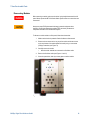
Safety Precautions
This manual describes the specifications and the proper usage of the BIT-2100A. All
usage beyond the specifications or the intended use is not recommended and might
cause impaired safety for the user.
Overview
The BIT-2100 Series Switch System consists of a frame, a controller module, and up
to five switch modules. It is intended to route RF signals through user-selectable
paths. There are different switch modules available for different applications. The
paths can be set via an LXI compliant network interface or a USB interface.
Components
The BIT-2100 Series is a modular system. Each instrument consists of a master frame
and optionally up to seven slave frames. The master frame always has the address 0
assigned, whereas the user can assign the addresses 1 through 7 to the slave frames.
The master module is connected to a PC which controls the entire instrument. All slave
frames are connected to the master frame.
Each frame contains up to five switch modules of different types:
•
An SP4T (single-pole, four-throw) module routes an incoming connector to
one of four outgoing connectors. The other outgoing connectors are
terminated with 50 Ω into ground. Alternatively, all outgoing connectors can
be disconnected, and the incoming connector leads into open
•
An SP6T (single-pole, six-throw) module routes an incoming connector to
one of four outgoing connectors. The other outgoing connectors are
terminated with 50 Ω into ground. Alternatively, all outgoing connectors can
be disconnected, and the incoming connector leads into open
•
An SPDT module has two, four, or six independent single-pole, double-throw
switches. Each switch routes an incoming connector to one of two outgoing
connectors; the other outgoing connector leads into open
An example configuration is shown in Figure 1.
BitifEye Digital Test Solutions GmbH
7