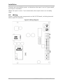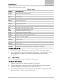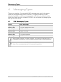
1
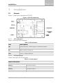
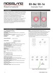
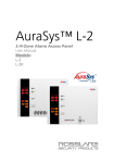
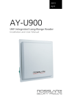
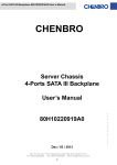
SA-59 GSM Communicator Installation and User Manual Copyright © 2015 by Rosslare. All rights reserved. This manual and the information contained herein are proprietary to ROSSLARE ENTERPRISES LIMITED and/or its related companies and/or subsidiaries’ (hereafter: "ROSSLARE"). Only ROSSLARE and its customers have the right to use the information. No part of this manual may be re-produced or transmitted in any form or by any means, electronic or mechanical, for any purpose, without the express written permission of ROSSLARE. ROSSLARE owns patents and patent applications, trademarks, copyrights, or other intellectual property rights covering the subject matter in this manual. TEXTS, IMAGES, AND ILLUSTRATIONS INCLUDING THEIR ARRANGEMENT IN THIS DOCUMENT ARE SUBJECT TO THE PROTECTION OF COPYRIGHT LAWS AND OTHER LEGAL RIGHTS WORLDWIDE. THEIR USE, REPRODUCTION, AND TRANSMITTAL TO THIRD PARTIES WITHOUT EXPRESS WRITTEN PERMISSION MAY RESULT IN LEGAL PROCEEDINGS. The furnishing of this manual to any party does not give that party or any third party any license to these patents, trademarks, copyrights or other intellectual property rights, except as expressly provided in any written agreement of ROSSLARE. ROSSLARE reserves the right to revise and change this document at any time, without being obliged to announce such revisions or changes beforehand or after the fact. Table of Contents Table of Contents 1. Introduction ....................................................................... 7 1.1 Overview ............................................................................................ 7 1.2 Main Features ..................................................................................... 7 2. Technical Specifications ................................................... 8 3. Installation ........................................................................ 9 3.1 General .............................................................................................. 9 3.1.1 LED Indicators ............................................................................................. 9 3.1.2 I/O Description ............................................................................................ 9 3.2 Wiring .............................................................................................. 10 3.3 Mounting ......................................................................................... 11 4. Messaging Types ............................................................. 12 4.1 SMS Messaging Types ....................................................................... 12 5. Programming................................................................... 13 5.1 Programming the System .................................................................. 13 5.1.1 Prefix Number Programming ...................................................................... 13 5.1.2 Phone Number Programming ..................................................................... 14 A. Limited Warranty ............................................................ 15 SA-59 Installation and User Manual iii List of Figures List of Figures Figure 1: SA-59 Components ......................................................................... 9 Figure 2: Wiring Diagram ............................................................................. 10 iv SA-59 Installation and User Manual List of Tables List of Tables Table 1: LED Indicators ................................................................................... 9 Table 2: I/O Description .................................................................................. 9 Table 3: Inputs ............................................................................................. 11 SA-59 Installation and User Manual v Notice and Disclaimer Notice and Disclaimer This manual’s sole purpose is to assist installers and/or users in the safe and efficient installation and usage of the system and/or product described herein. BEFORE ATTEMPTING TO INSTALL AND/OR USE THE SYSTEM, THE INSTALLER AND THE USER MUST READ THIS MANUAL AND BECOME FAMILIAR WITH ALL SAFETY REQUIREMENTS AND OPERATING PROCEDURES. The system must not be used for purposes other than those for which it was designed. The use of the software associated with the system and/or product, if applicable, is subject to the terms of the license provided as part of the purchase documents. ROSSLARE exclusive warranty and liability is limited to the warranty and liability statement provided in an appendix at the end of this document. This manual describes the maximum configuration of the system with the maximum number of functions, including future options. Therefore, not all functions described in this manual may be available in the specific system and/or product configuration you purchased. Incorrect operation or installation, or failure of the user to effectively maintain the system, relieves the manufacturer (and seller) from all or any responsibility for consequent noncompliance, damage, or injury. The text, images and graphics contained in the manual are for the purpose of illustration and reference only. All data contained herein is subject to change without prior notice. In no event shall manufacturer be liable for any special, direct, indirect, incidental, consequential, exemplary or punitive damages (including, without limitation, any and all damages from business interruption, loss of profits or revenue, cost of capital or loss of use of any property or capital or injury). All graphics in this manual are for reference only, some deviation between the image(s) and the actual product may occur. All wiring diagrams are intended for reference only, the photograph or graphic of the PCB(s) are intended for clearer illustration and understanding of the product and may differ from the actual PCB(s). vi SA-59 Installation and User Manual Introduction 1. Introduction 1.1 Overview The SA-59 is a universal GSM reporting unit and communicator. When it is connected to an alarm panel, the SA-59 operates as a GSM backup unit to the PSTN line, enabling outgoing calls to be redirected to the GSM network if the PSTN line fails. Since the SA-59 simulates a telephone line, it makes no difference whether the device to which it is connected is a GSM or a land line. The built-in SA-59 GSM module connects via the PSTN line to check for phone communication type availability. If there is no PSTN line, the SA-59 automatically switches the call from PSTN line to GSM. When an event occurs, the alarm system calls the PSTN line to report an alarm. Instructions to arm or disarm, check sensors and other facilities of the system are relayed via system codes or a phone pad and voice menu, depending on the system to which it is connected. When the SA-59 is connected to a telephone line (Line IN), the SA-59 directs the device to a land line to make a call. If the land line is cut or not functioning, all communications go via the GSM network without the need for any special additional settings. If the SA-59 is not connected to a land line, all communications take place via the GSM network. The SA-59 incorporates a SIM interface that conforms to the GSM 11.11 and GSM 11.12 standards, which are based on the ISO/IEC 7816 standard. These standards define the electrical, signaling, and protocol specifications of a GSM SIM card. 1.2 Main Features SA-59 uses GSM standard to back up the hardwired telephone line (PSTN) in a case where PSTN line is cut or tampered with on the alarm panel side. The SA-59 has a battery charger and a space for Rosslare’s BT-16, 12 VDC, 2000 mAh NiMH type (Nickel-Metal Hydridea) backup battery. There are 4 inputs in which a change in the input voltage level changes the corresponding output. This applies when 0 is connection to ground and 1 is has infinite impedance. SA-59 Installation and User Manual 7 Technical Specifications 2. Technical Specifications Electronic Specifications Voltage 14 V, 2A Maximum Power Consumption 1.2 A, when power supply is 14 V Standby Current 0.2 A, when power supply is 14 V Battery Option for backup battery of up to 12 VDC, 7 Ah and local charger for the battery Connector Output 3 open collector outputs of 200 mA Relay 1 Form-C 1A relay related to Input 1 Telephone Lines Telephone line-out and telephone line-in LEDs 5 LED indications Connections PSTN Telephone Line-IN Connected to the main telephone line in the premises before any other connection Telephone Line-OUT Should be connected to the alarm system Environmental Characteristics Operating Temp. Range 0°C to 60°C (32°F to 140°F) Operating Humidity Range 0 to 95% (non-condensing) Physical Characteristics Dimensions (H x W x D) 162 x 223 x 35 mm (6.4 x 8.8 x 1.4 in.) Weight 435 g (15.3 oz) 8 SA-59 Installation and User Manual Installation 3. Installation 3.1 General Figure 1 shows the components of SA-59. Figure 1: SA-59 Components 3.1.1 LED Indicators Table 1 shows the LED indicators. Table 1: LED Indicators LED Description LD1 GSM Power ON – Power supply is connected to device D3 Transmission – Transmission of signal to antenna D4 Reset – Reset in power up D1 GSM Power up ready – Power up the device LD21 Dialing – telephone/device 3.1.2 I/O Description Table 2 describes the I/O activation. Table 2: I/O Description Input Activation Input activation triggers the outputs in the following order: Input 1 Activate Output 1 Input 2 Activate Output 2 Input 3 Activate Output 3 Input 4 Activate Relay SA-59 Installation and User Manual 9 Installation Outputs are controlled by inputs, so that when the input is set to 0 (grounded), the output is activated. When the input is set to 1 (not connected), the output returns to its steady state. 3.2 Wiring Figure 2 shows the main components on the SA-59 board, including terminal blocks and LED indicators. Figure 2: Wiring Diagram 10 SA-59 Installation and User Manual Installation Table 3 lists the various inputs. Table 3: Inputs Input Description V IN + Input power PLUS connection V IN - Input power MINUS connection BAT + Battery PLUS BAT - Battery MINUS OUT 1 Open collector Out 1 OUT 2 Open collector Out 2 OUT 3 Open collector Out 3 +12V 12 VDC, 100 mA, output NO Normally Open connection of relay NC Normally Close connection of relay COM Common connection of relay L Off Open collector line OFF output G Off Open collector GSM module off output +12V 12 VDC, 100 mA, output Input 1 Logical input 1, tamper input Input 2 Logical input 2 Input 3 Logical input 3 Input 4 Logical input 4 Line OUT Telephone Line OUT (from system to telephone device) Line IN Telephone Line IN (from the entrance point to the system) To w ire the SA-59: 1. 2. 3.3 Connect Line IN to the phone line and Line OUT to the alarm sytem. It is suggested to connect the tamper to the Input 1 and Output 1 to the alarm system to receive an indication of tampering with the unit’s enclosure. Mounting The SA-59 mounts on a wall using the unit’s casing. To mount the casing: 1. Make 4 holes for the casing and attach to the wall. 2. 3. 4. Thread cables along the back cover into the panel via holes provided. Add the battery and then wire the battery to BAT +/-. Close box by clipping the three clips at the top and pushing down and tightening the 3 screws at the bottom side. SA-59 Installation and User Manual 11 Messaging Types 4. Messaging Types There are a number of recognizable SMS message types which the system sends to preprogrammed phone numbers. The system memory holds 4 telephone numbers enabling messaging and notification to relevant parties when the Alarm System is violated. All SMS’s are controlled by changing the 4th input in the SA-59. 4.1 SMS Messaging Types Input Sent Message Input 1 high: "SYSTEM TROUBLE" Input 1 low: "SYSTEM TROUBLE RESTORE" Input 2 high: "PANIC ALARM" Input 2 low: "PANIC RESTORE" Input 3 high: "SYSTEM ARMED" Input 3 low: "SYSTEM DISARMED" Input 4 high: "SYSTEM ALARM" When system indicates “SYSTEM TROUBLE”, the input has switched from 0 V (connected to ground) to a non-connected state (tri-state or high impedance). When system indicates “SYSTEM TROUBLE RESTORE”, the input has switched from a non-connected state to 0 V (connected to ground). 12 SA-59 Installation and User Manual Limited Warranty 5. Programming 5.1 Programming the System Prior to programming, make sure a telephone is connected but do not connect the unit to a PSTN line. To prepare the unit for programming: 1. Connect the telephone to "Line OUT". 2. 3. Wait for a dial tone. Ensure that the SA-59 is not connected to PSTN lines. The default installer code is 5555. 5.1.1 Prefix Number Programming When using the GSM network, the addition of a prefix number may be needed. The prefix number is user programmable. To program the prefix number: 1. Press 5555 to enter Program mode. 2. Press 1. 3. Type the prefix number. 4. Press # to confirm. The unit beeps. Example: For prefix number 9, press: 5555 1 9 # To delete the prefix number: 1. Press 5555 to enter Program mode. 2. Press 1. 3. Press # to confirm. The unit beeps. Example: Press: 5555 1 # SA-59 Installation and User Manual 13 Limited Warranty 5.1.2 Phone Number Programming Up to three numbers can be programmed into the SA-59 unit, to which the system sends an SMS message in the event of an event or alarm. To program the first phone number: 1. Press 5555 to enter Program mode. 2. Press 2. 3. Type the phone number. 4. Press # to confirm. The unit beeps. Example: For number 052646666, press: 5555 2 052646666 # To program additional phone numbers: 1. Press 5555 to enter Program mode. 2. Press 3. For the third phone number Press 4 instead of 3. 3. Type the prefix number. 4. Press # to confirm. The unit beeps. Example: For the number 052525222, press: 5555 3 052525222 # To delete phone numbers: 1. Press 5555 to enter Program mode. 2. Press 2. To delete the next number, press the next consecutive number. 3. Press # to confirm. The unit beeps. Example: Press: 5555 2 # 14 SA-59 Installation and User Manual Limited Warranty A. Limited Warranty The full ROSSLARE Limited Warranty Statement is available in the Quick Links section on the ROSSLARE website at www.rosslaresecurity.com. Rosslare considers any use of this product as agreement to the Warranty Terms even if you do not review them. SA-59 Installation and User Manual 15 SA-59 Rosslare Enterprises Ltd. Kowloon Bay, Hong Kong Tel: +852-2795-5630 Fax: +852-2795-1508 [email protected] United States and Canada Rosslare Security Products, Inc. Southlake, TX, USA Toll Free: +1-866-632-1101 Local: +1-817-305-0006 Fax: +1-817-305-0069 [email protected] Europe Rosslare Israel Ltd. Rosh HaAyin, Israel Tel: +972-3-938-6838 Fax: +972-3-938-6830 [email protected] Latin America Rosslare Latin America Buenos Aires, Argentina Tel: +54-11-4001-3104 [email protected] China Rosslare Electronics (Shenzhen) Ltd. Shenzhen, China Tel: +86-755-8610-6842 Fax: +86-755-8610-6101 [email protected] India Rosslare Electronics India Pvt Ltd. Tel/Fax: +91-20-40147830 Mobile: +91-9975768824 [email protected] 0706-0960294+01 Asia Pacific, Middle East, Africa