1
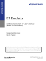
User’s Manual
E1 Emulator
Additional Document for User’s Manual
(Notes on Connection)
Supported Devices:
RL78 Family
All information contained in these materials, including products and product specifications,
represents information on the product at the time of publication and is subject to change by
Renesas Electronics Corp. without notice. Please review the latest information published by
Renesas Electronics Corp. through various means, including the Renesas Technology Corp.
website (http://www.renesas.com).
www.renesas.com
R20UT0694ED0100, Rev. 1.00
June 6, 2011
Notice
•
All information included in this document is current as of the date this document is issued. Such information, however, is subject to
change without any prior notice. Before purchasing or using any Renesas Electronics products listed herein, please confirm the
latest product information with a Renesas Electronics sales office. Also, please pay regular and careful attention to additional and
different information to be disclosed by Renesas Electronics such as that disclosed through our website.
Renesas Electronics does not assume any liability for infringement of patents, copyrights, or other intellectual property rights of third
parties by or arising from the use of Renesas Electronics products or technical information described in this document. No license,
express, implied or otherwise, is granted hereby under any patents, copyrights or other intellectual property rights of Renesas Electronics
or others.
You should not alter, modify, copy, or otherwise misappropriate any Renesas Electronics product, whether in whole or in part.
Descriptions of circuits, software and other related information in this document are provided only to illustrate the operation of
semiconductor products and application examples. You are fully responsible for the incorporation of these circuits, software, and
information in the design of your equipment. Renesas Electronics assumes no responsibility for any losses incurred by you or third parties
arising from the use of these circuits, software, or information.
When exporting the products or technology described in this document, you should comply with the applicable export control laws and
regulations and follow the procedures required by such laws and regulations. You should not use Renesas Electronics products or the
technology described in this document for any purpose relating to military applications or use by the military, including but not limited to
the development of weapons of mass destruction. Renesas Electronics products and technology may not be used for or incorporated into
any products or systems whose manufacture, use, or sale is prohibited under any applicable domestic or foreign laws or regulations.
Renesas Electronics has used reasonable care in preparing the information included in this document, but Renesas Electronics does not
warrant that such information is error free. Renesas Electronics assumes no liability whatsoever for any damages incurred by you
resulting from errors in or omissions from the information included herein.
Renesas Electronics products are classified according to the following three quality grades: "Standard", "High Quality", and "Specific". The
recommended applications for each Renesas Electronics product depends on the product's quality grade, as indicated below. You must
check the quality grade of each Renesas Electronics product before using it in a particular application. You may not use any Renesas
Electronics product for any application categorized as "Specific" without the prior written consent of Renesas Electronics. Further, you
may not use any Renesas Electronics product for any application for which it is not intended without the prior written consent of Renesas
Electronics. Renesas Electronics shall not be in any way liable for any damages or losses incurred by you or third parties arising from the
use of any Renesas Electronics product for an application categorized as "Specific" or for which the product is not intended where you
have failed to obtain the prior written consent of Renesas Electronics.
The quality grade of each Renesas Electronics product is “Standard” unless otherwise expressly specified in a Renesas Electronics
data sheets or data books, etc.
“Standard”:
Computers; office equipment; communications equipment; test and measurement equipment; audio and visual
equipment; home electronic appliances; machine tools; personal electronic equipment; and industrial robots.
“High Quality”:
Transportation equipment (automobiles, trains, ships, etc.); traffic control systems; anti-disaster systems; anticrime systems; safety equipment; and medical equipment not specifically designed for life support.
“Specific”:
Aircraft; aerospace equipment; submersible repeaters; nuclear reactor control systems;medical equipment or
systems for life support (e.g. artificial life support devices or systems), surgical implantations, or healthcare
intervention (e.g. excision, etc.), and any other applications or purposes that pose a direct threat to human life.
You should use the Renesas Electronics products described in this document within the range specified by Renesas Electronics,
especially with respect to the maximum rating, operating supply voltage range, movement power voltage range, heat radiation
characteristics, installation and other product characteristics. Renesas Electronics shall have no liability for malfunctions or damages
arising out of the use of Renesas Electronics products beyond such specified ranges.
Although Renesas Electronics endeavors to improve the quality and reliability of its products, semiconductor products have specific
characteristics such as the occurrence of failure at a certain rate and malfunctions under certain use conditions. Further, Renesas
Electronics products are not subject to radiation resistance design. Please be sure to implement safety measures to guard them against
the possibility of physical injury, and injury or damage caused by fire in the event of the failure of a Renesas Electronics product, such as
safety design for hardware and software including but not limited to redundancy, fire control and malfunction prevention, appropriate
treatment for aging degradation or any other appropriate measures. Because the evaluation of microcomputer software alone is very
difficult, please evaluate the safety of the final products or system manufactured by you.
Please contact a Renesas Electronics sales office for details as to environmental matters such as the environmental compatibility of each
Renesas Electronics product. Please use Renesas Electronics products in compliance with all applicable laws and regulations that
regulate the inclusion or use of controlled substances, including without limitation, the EU RoHS Directive. Renesas Electronics assumes
no liability for damages or losses occurring as a result of your noncompliance with applicable laws and regulations.
This document may not be reproduced or duplicated, in any form, in whole or in part, without prior written consent of Renesas Electronics.
Please contact a Renesas Electronics sales office if you have any questions regarding the information contained in this document or
Renesas Electronics products, or if you have any other inquiries.
(Note 1) "Renesas Electronics" as used in this document means Renesas Electronics Corporation and also includes its majorityowned subsidiaries.
(Note 2) "Renesas Electronics product(s)" means any product developed or manufactured by or for Renesas Electronics.
Contents
Table of Contents
Chapter 1
1.1
1.2
Chapter 2
2.1
2.2
2.3
Outline ...................................................................................................4
Features ...................................................................................................................................4
Configuration of Manuals .........................................................................................................4
Designing the User System .................................................................5
Connecting the Emulator with the User System ......................................................................5
Pin Assignment of the Connector on the User System ...........................................................6
Recommend Circuit between the Connector and the CPU .....................................................7
2.3.1
Recommend Circuit Connection......................................................................................7
2.3.2
Regarding Connection of RESET.....................................................................................7
Chapter 3
Specification .......................................................................................10
Chapter 4
Notes on Usage...................................................................................11
4.1
4.2
List .......................................................................................................................................11
Details ....................................................................................................................................11
R20UT0694ED0000 Rev. 1.00
6. June 2011
Page 3 of 15
Outline
Chapter 1 Outline
1.1
Features
E1 Emulator is an on-chip debug emulator with flash programming function, which is
used for debugging and programming a program to be embedded in on-chip flash
memory microcontrollers. This product can debug with the target microcontroller
connected to the user system, and can write programs to the on-chip flash memory of
microcontrollers.
1.2
Configuration of Manuals
Documentation for the E1/E20 emulator manual is in two parts: the E1/E20 Emulator
User’s Manual and the E1/E20 Emulator Supplementary Document for the User’s Manual
(this manual). Different versions of the latter correspond to different sets of MCU. Be sure
to read both of the manuals before using the E1/E20 emulator (hereinafter referred to as
"the emulator").
The E1/E20 emulator user’s manual has the following contents:
•
Components of the emulators
•
Emulator hardware specification
•
Connection to the emulator and the host computer and user system
The E1/E20 Emulator Supplementary Document for the User’s Manual has the following
contents:
•
For use in hardware design, an example of connection and the interface circuit
required to connect the emulator.
•
Notes on using the emulator
•
Software specifications and so on for using each microcomputers
R20UT0694ED0000 Rev. 1.00
6. June 2011
Page 4 of 15
Designing the User System
Chapter 2 Designing the User System
To connect the E1 emulator (hereinafter referred to as the emulator), a connector for the
user system interface cable must be mounted on the user system. When designing the
user system, read this section of this manual and the hardware manual for the MCUs.
2.1
Connecting the Emulator with the User System
Table 2-1 shows the connector type numbers of the E1 emulators.
Table 2-1 Connector Type Numbers
Type
Manufacturer
Specifications
Number
14-pin
7614-6002
Sumitomo 3M Limited
14-pin straight type (Japan)
Connector
2514-6002
3M Limited
14-pin straight type (other countries)
Figures 2-1 and 2-2 show examples of the connection between a user system interface
cable of the 14-pin type. Do not mount other components with a height exceeding 10 mm
within 5 mm of the connector on the user system.
Figure 2-1 Connecting the User System Interface Cable to the 14-pin Connector of the E1
Emulator
14-pin user system interface cable
14-pin type connector
User system
Top View
5mm
2
4
6
8
10 12 14
1
3
5
7
9
11 13
5mm
5mm
5mm
Area with limit on mounted components
(heights must be no greater than 10mm)
R20UT0694ED0000 Rev. 1.00
6. June 2011
Page 5 of 15
Designing the User System
2.2
Pin Assignment of the Connector on the User System
Table 2-2 shows the pin assignments of the 14-pin connectors.
Table 2-2 Pin assignments of the connector (14-pin)
Pin No.
Signal (
Input/Outputnote
:Low Active)
1
R.F.U
-
2
GND
-
3
R.F.U
-
4
R.F.U
-
5
TOOL0
Input/Output
6
TRESET
Input
7
R.F.U
-
8
VDD
-
9
EMVDD
-
10
RESET
Output
11
R.F.U
-
12
GND
-
13
RESET
Output
14
GND
-
Note: Input to or output from the emulator
R20UT0694ED0000 Rev. 1.00
6. June 2011
Page 6 of 15
Designing the User System
2.3
Recommend Circuit between the Connector and the CPU
2.3.1 Recommend Circuit Connection
Refer to Figure 2-2 and design an appropriate circuit.
Be sure to take into consideration the specifications of the target device as well as
measures to prevent noise when designing your circuit.
Figure 2-2 Recommended Circuit Connection
Note 1
The circuit enclosed by a dashed line is not required when only flash programming is performed.
Note 2
Pull-up resistor is not required if the reset circuit on the user system contains no buffers and the reset
signal is only generated via resistors or capacitors.
Note 3
The drive power supply of TOOL0 is different depending on devices. Defer to user’s manual of device.
2.3.2 Regarding Connection of RESET
This section describes the connection of the reset pin, for which special attention must be
paid, in the circuit connection example shown in the previous section.
During on-chip debugging, a reset signal from the user system is input to the emulator,
masked, and then output to the target device. Therefore, the reset signal connection
varies depending on whether the emulator is connected.
For flash programming, the circuit must be designed so that the reset signals of the user
system and the emulator do not conflict.
Select one of the following methods and connect the reset signal in the circuit. The
details of each method are described on the following pages.
(1)
Automatically switching the reset signal via series resistor (recommended;
described in recommended circuit connection in the previous section)
(2)
Manually switching the reset signal with jumper
(3)
Resetting the target device by power-on reset (POR) only
R20UT0694ED0000 Rev. 1.00
6. June 2011
Page 7 of 15
Designing the User System
(1) Automatically switching the reset signal via series resistor
Figure 2-3 illustrates the reset pin connection described in 2.3.1 Recommend Circuit
Connection.
This connection is designed assuming that the reset circuit on the user system contains
an N-ch open-drain buffer (output resistance: 100Ω or less). The VDD or GND level may
be unstable when the logic of TRESET / RESET of the emulator is inverted, so observe
the conditions described below in Remark.
Figure 2-3 Circuit Connection with Reset Circuit That Contains Buffer
Remark
Make the resistance of R1 at least ten times that of R2, R1 being 10 kΩ or more.
Pull-up resistor R2 is not required if the buffer of the reset circuit consists of CMOS output.
The circuit enclosed by a dashed line is not required when only flash programming is performed.
Figure 2-4 illustrates the circuit connection for the case where the reset circuit on the
user system contains no buffers and the reset signal is only generated via resistors or
capacitors. Design the circuit, observing the conditions described below in Remark.
Figure 2-4 Circuit Connection with Reset Circuit That Contains No Buffers
Remark
Make the resistance of R1 at least ten times that of R2, R1 being 10 kΩ or more.
The circuit enclosed by a dashed line is not required when only flash programming is performed.
(2) Manually switching the reset signal with jumper
Figure 2-5 illustrates the circuit connection for the case where the reset signal is switched
using the jumper, with or without the emulator connected. This connection is simple, but
the jumper must be set manually.
R20UT0694ED0000 Rev. 1.00
6. June 2011
Page 8 of 15
Designing the User System
Figure 2-5 Circuit in connection for Switching Reset Signal with Jumper
(3) Resetting the target device by power-on reset (POR) only
Figure 2-6 illustrates the circuit connection for the case where the target device is only
reset via POR without using the reset pin. RESET is valid only when the debugger is
running or during flash programming.
Do not turn off a power supply of the user system during a break.
Figure 2-6 Circuit Connection for the Case Where Target Device Is Only Reset via POR
R20UT0694ED0000 Rev. 1.00
6. June 2011
Page 9 of 15
Specification
Chapter 3 Specification
Specifications are shown in Table 3-1 below.
Table 3-1 E1 Specification
Large Item
Hardware
Common
Middle Item
Small Item
Target host machine
Computer equipped with a USB port
OS is due to the software tool.
User system interface
14-pin connector
Host machine interface
USB2.0 (Full speed/ High speed)
Connection to the user system
Connection by the provided user-system
interface cable
Power supply function
3.3V or 5.0V, set in software tool, can be
supplied to the user system from VDD pin of
the emulator (with current up to 200 mA)
Power supply for the emulator
No need (the host computer supplies power
through the USB)
Software break
2000 points
Hardware break
1points (commonly used by execution and
access)
Forced break
Available
Number of events
1points (commonly used by execution and
access)
Available function
Only hardware break
Break
Event
Related
debugging
Trace
Performance
measurement
Related
programming
Unavailable
Measurement item
From run to break
Performance
Resolution 100us, Max. measurement time
100 hour
Real time RAM monitor
Available (CPU is used when monitoring)
Direct memory modification
Available (CPU is used when executing)
Hot plug-in
Unavailable
Security
10-byte ID code authentication
Clock supply
Clock mounted on the user system can be
used
Security flag setting
Standalone operation
R20UT0694ED0000 Rev. 1.00
6. June 2011
Specification
Available
Unavailable (must be connected to host
machine)
Page 10 of 15
Notes on Usage
Chapter 4 Notes on Usage
Make sure to read the notes on usage in this section.
4.1
List
Table 4-1 List of notes on usage
No.
4.2
Item
1
Handling of device that was used for debugging
2
Flash self programming
3
Operation after reset
4
Operation when debugger starts
5
Operation at voltage with which flash memory cannot be written
6
On-chip debugging option byte setting (address C3H)
7
Pseudo real-time RAM monitor function
Details
No. 1 Handling of device that was used for debugging
Do not mount a device that was used for debugging on a mass-produced product,
because the flash memory was rewritten during debugging and the number of
rewrites of the flash memory cannot be guaranteed.
Moreover, do not embed the debug monitor program into mass-produced products.
No. 2 Flash self programming
If a space where the debug monitor program is allocated is rewritten by flash self
programming, the debugger can no longer operate normally. This caution also applies
to boot swapping for such an area
No. 3 Operation after reset
After an external pin reset or internal reset, the monitor program performs debug
initialization processing. Consequently, the time from reset occurrence until user
program execution differs from that in the actual device operation. If “No” is selected
in the Permit Flash Programming of the debug tool property, the time until the user
program is executed compared with the time when “Yes” is selected is delayed
several 100 ms.
No. 4 Operation when debugger starts
When the debugger is started and there is no the debug monitor program in device to
debug, the internal flash memory is erased.
No. 5 Operation at voltage with which flash memory cannot be written
If any of the following debugger operations <1> to <7>, which involve flash memory
rewriting, is performed while flash memory cannot be rewritten, the debugger
automatically changes the register setting so as to enable flash memory rewriting,
and restores the register setting after the operation is completed. If any of the
R20UT0694ED0000 Rev. 1.00
6. June 2011
Page 11 of 15
Notes on Usage
following operations <1> to <7> is performed while flash memory rewriting has been
disabled or operation is performed at a voltage with which flash memory cannot be
rewritten, however, the debugger outputs an error and the operation is ignored.
<1> Writing to internal flash memory
<2> Setting or canceling of software breakpoint
<3> Starting execution at the set software breakpoint position
<4> Step execution at the set software breakpoint position
<5> Step-over execution, Return Out execution
<6> Come Here
<7> If permit is selected in the Flash Programming area in the Configuration dialog
box, the following operations cannot be performed.
a) Setting, changing, or canceling of hardware breaks
b) Masking/unmasking of internal reset
c) Switching of peripheral breaks
No. 6 On-chip debugging option byte setting (address C3H)
The on-chip debugging option byte setting is rewritten arbitrarily by the debugger.
No. 7 Pseudo real-time RAM monitor function
Note the following points when using the pseudo real-time RAM monitor function.
<1> Standby mode (HALT or STOP) may be cancelled during monitoring.
<2> The pseudo real-time RAM monitor function does not operate while the CPU
operating clock is stopped.
<3> The pseudo real-time RAM monitor function does not operate while the self
programming execution.
R20UT0694ED0000 Rev. 1.00
6. June 2011
Page 12 of 15
E1 Emulator
Additional Document for Preliminary User's Manual (Notes on Connection
Publication Date:
Published by:
Rev.1.00
Jun 06, 2011
Renesas Electronics Europe GmbH
http://www.renesas.com
SALES OFFICES
Refer to "http://www.renesas.com/" for the latest and detailed information.
Renesas Electronics America Inc.
2880 Scott Boulevard Santa Clara, CA 95050-2554, U.S.A.
Tel: +1-408-588-6000, Fax: +1-408-588-6130
Renesas Electronics Canada Limited
1101 Nicholson Road, Newmarket, Ontario L3Y 9C3, Canada
Tel: +1-905-898-5441, Fax: +1-905-898-3220
Renesas Electronics Europe Limited
Dukes Meadow, Millboard Road, Bourne End, Buckinghamshire, SL8 5FH, U.K
Tel: +44-1628-585-100, Fax: +44-1628-585-900
Renesas Electronics Europe GmbH
Arcadiastrasse 10, 40472 Düsseldorf, Germany
Tel: +49-211-65030, Fax: +49-211-6503-1327
Renesas Electronics (China) Co., Ltd.
7th Floor, Quantum Plaza, No.27 ZhiChunLu Haidian District, Beijing 100083, P.R.China
Tel: +86-10-8235-1155, Fax: +86-10-8235-7679
Renesas Electronics (Shanghai) Co., Ltd.
Unit 204, 205, AZIA Center, No.1233 Lujiazui Ring Rd., Pudong District, Shanghai 200120, China
Tel: +86-21-5877-1818, Fax: +86-21-6887-7858 / -7898
Renesas Electronics Hong Kong Limited
Unit 1601-1613, 16/F., Tower 2, Grand Century Place, 193 Prince Edward Road West, Mongkok, Kowloon, Hong Kong
Tel: +852-2886-9318, Fax: +852 2886-9022/9044
Renesas Electronics Taiwan Co., Ltd.
7F, No. 363 Fu Shing North Road Taipei, Taiwan
Tel: +886-2-8175-9600, Fax: +886 2-8175-9670
Renesas Electronics Singapore Pte. Ltd.
1 harbourFront Avenue, #06-10, keppel Bay Tower, Singapore 098632
Tel: +65-6213-0200, Fax: +65-6278-8001
Renesas Electronics Malaysia Sdn.Bhd.
Unit 906, Block B, Menara Amcorp, Amcorp Trade Centre, No. 18, Jln Persiaran Barat, 46050 Petaling Jaya, Selangor Darul Ehsan, Malaysia
Tel: +60-3-7955-9390, Fax: +60-3-7955-9510
Renesas Electronics Korea Co., Ltd.
11F., Samik Lavied' or Bldg., 720-2 Yeoksam-Dong, Kangnam-Ku, Seoul 135-080, Korea
Tel: +82-2-558-3737, Fax: +82-2-558-5141
© 2010 Renesas Electronics Corporation. All rights reserved.
Colophon 1.0
E1 Emulator
Additional Document for User’s Manual
(Notes on Connection)