1
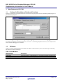
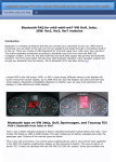
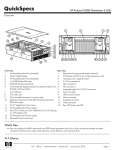
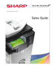
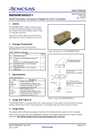
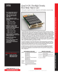
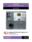
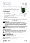
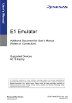
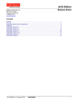
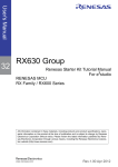
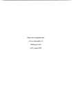
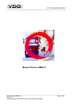
H8S, H8/300 Series Simulator/Debugger V.5.09.00
Supplementary Information for User’s Manual
REJ10J2187-0100
Rev.1.00
May. 12, 2010
Introduction
This document describes how V.5.09.00 of the H8S, H8/300 Series Simulator/Debugger differs from V.5.06.00,
V.5.07.00, and V.5.08.00. Before using the simulator/debugger, carefully read this document, the H8S, H8/300 Series
Simulator/Debugger User’s Manual, and the online help for the H8S, H8/300 Series Simulator/Debugger.
Contents
1.
1.1
1.2
1.3
New Features in V.5.07.00................................................................................................................ 2
Settings for Simulation of Peripheral Functions ................................................................................ 2
Windows............................................................................................................................................ 2
Command Line .................................................................................................................................. 3
2. New Features in V.5.08.00................................................................................................................ 4
2.1 Support for the V2 Core of the H8SX Series .................................................................................... 4
2.1.1 Range of Simulation..................................................................................................................... 4
2.1.2 Fetch Mode .................................................................................................................................. 4
2.1.3 Endian .......................................................................................................................................... 4
2.1.4 Exception ..................................................................................................................................... 4
2.2 Windows............................................................................................................................................ 4
3. New Features in V.5.09.00................................................................................................................ 5
3.1 Starting up the Simulator/Debugger.................................................................................................. 5
3.2 Modifying the Simulator/Debugger Settings...................................................................................... 5
3.2.1 Setting the Number of Bits in the Data Space and Program Area............................................... 5
3.3 Using the Simulator/Debugger Breakpoints ...................................................................................... 6
3.3.1 Setting a Breakpoint..................................................................................................................... 6
3.4 Command Line .................................................................................................................................. 7
REJ10J2187-0100 Rev.1.00
May. 12, 2010
Page 1 of 8
H8S, H8/300 Series Simulator/Debugger V.5.09.00
Supplementary Information for User’s Manual
1.
1.1
New Features in V.5.07.00
Settings for Simulation of Peripheral Functions
Settings for simulation of peripheral functions can be made on the [Peripheral Function Simulation] tabbed page of the
[Set Simulator] dialog box.
Figure 1.1 [Set Simulator] Dialog Box ([Peripheral Function Simulation] Page)
For details on simulation of peripheral functions, see section 3.3, Simulating Peripheral Functions, in the H8S, H8/300
Series Simulator/Debugger User’s Manual.
1.2
Windows
Table 1.1 lists the windows that have been added. For details on these windows, refer to the online help for the H8S,
H8/300 Series Simulator/Debugger.
Table 1.1 New Windows
Window Name
OS Object
Task Trace
Task Analyze
REJ10J2187-0100 Rev.1.00
May. 12, 2010
Description
Shows the states of OS objects such as tasks and semaphores.
Shows the history of task execution in a program that uses a real time OS.
Shows the current CPU occupancy.
Page 2 of 8
H8S, H8/300 Series Simulator/Debugger V.5.09.00
Supplementary Information for User’s Manual
1.3
Command Line
Table 1.2 lists the commands that have been added. For details on the command syntax, refer to the online help for the
H8S, H8/300 Series Simulator/Debugger.
Table 1.2 New Commands
Command
OSOBJECT_ALL_ADD
OSOBJECT_ALL_DELETE
OSOBJECT_AUTO_UPDATE
Abbreviation
OAA
OAD
OAU
OSOBJECT_DATA_LOWLINE
OSOBJECT_DATA_SAVE
OSOBJECT_DATA_UPLINE
OSOBJECT_DISPLAY
OSOBJECT_NO_UPDATE
OSOBJECT_ONE_ADD
OSOBJECT_ONE_DELETE
OSOBJECT_ONE_EDIT
OSOBJECT_SETTING_LOAD
OSOBJECT_SETTING_SAVE
OSOBJECT_STOP_UPDATE
ODU
ODS
ODL
OD
ONU
OOA
OOD
OOE
OSL
OSS
OSU
REJ10J2187-0100 Rev.1.00
May. 12, 2010
Description
Adds OS objects (of a specific object type)
Deletes OS objects (in a specific sheet)
Changes the automatic-update setting to “Auto” and
“Break”.
Moves an OS object to the next line.
Saves the information on an OS object to a file.
Moves an OS object to the previous line.
Shows the information on an OS object.
Changes the automatic-update setting to “Lock”.
Adds an OS object.
Deletes an OS object.
Edits an OS object.
Loads OS-object settings from a file.
Saves OS-object settings in a file.
Changes the automatic-update setting to “Break”.
Page 3 of 8
H8S, H8/300 Series Simulator/Debugger V.5.09.00
Supplementary Information for User’s Manual
2.
New Features in V.5.08.00
2.1
Support for the V2 Core of the H8SX Series
The V2 core of the H8SX series is newly supported. The target name for the V2 core is “H8SX(V2) Simulator”.
2.1.1
Range of Simulation
The simulator/debugger for the H8SX V2 core supports the following CPU functions.
Table 2.1 CPU Functions Supported by the Simulator/Debugger for the H8SX V2 Core
Name of the
Debugging Platform
H8SX (V2)
[Note] c: Supported
⎯: Not supported
U: Partly supported
Endian
⎯
Control
Register
c
Timer
U
Differences in the simulator/debugger operation compared to that for the other H8SX-series MCUs are given in the
following sections.
2.1.2
Fetch Mode
The simulator/debugger for the H8SX V2 core supports the 32-bit fetch mode.
2.1.3
Endian
The simulator/debugger for the H8SX V2 core supports big endian.
2.1.4
Exception
The simulator/debugger for the H8SX V2 core supports neither the address error exception nor the trace exception.
2.2
Windows
Table 2.2 shows a window that has been modified. For details on these windows, refer to the online help for the H8S,
H8/300 Series Simulator/Debugger.
Table 2.2 Modified Window
Window Name
Memory
REJ10J2187-0100 Rev.1.00
May. 12, 2010
Description
Modified to support the automatic update function.
Page 4 of 8
H8S, H8/300 Series Simulator/Debugger V.5.09.00
Supplementary Information for User’s Manual
3.
New Features in V.5.09.00
3.1
Starting up the Simulator/Debugger
V.5.09.00 of the simulator/debugger can be connected or disconnected via the [Debug] menu or by clicking on a toolbar
button. This section describes how to connect or disconnect the simulator/debugger in that way.
You can connect to the simulator/debugger by selecting a session file in which simulator/debugger settings have already
been defined. When you have selected targets in the process of creating a project, the number of session files is the
same as the number of selected targets. Select the session file that corresponds to the current target from the drop-down
list shown in figure 3.1.
Figure 3.1 Selecting a Session File
If you have selected a session file with which the simulator/debugger has been registered but the simulator/debugger is
disconnected, select [Debug -> Connect] or click on the [Connect] toolbar button .
To disconnect the simulator/debugger, on the other hand, select [Debug -> Disconnect] or click on the [Disconnect]
toolbar button .
3.2
Modifying the Simulator/Debugger Settings
The way of setting the number of bits in the data space and program area by the H8S-series simulator/debugger has
been changed. This section describes how to make these settings in V.5.09.00.
3.2.1
Setting the Number of Bits in the Data Space and Program Area
The number of bits in the data space and program area should be set on the [CPU Configuration] tabbed page in the [Set
Simulator] dialog box, which is displayed on initiation of the simulator/debugger.
Figure 3.2 [Set Simulator] Dialog Box ([CPU Configuration] Page)
REJ10J2187-0100 Rev.1.00
May. 12, 2010
Page 5 of 8
H8S, H8/300 Series Simulator/Debugger V.5.09.00
Supplementary Information for User’s Manual
The following items can be specified on this page:
[Data Area Bit Size]
Number of bits in the data space. The following values can be set for each CPU:
H8S/2600N and H8S/2000N: 16
H8S/2600A and H8S/2000A: 17 to 32
[Program Area Bit Size]
Number of bits in the program area. The following values can be set for each CPU:
H8S/2600N and H8S/2000N: 16
H8S/2600A and H8S/2000A: 17 to 24
After setting [Data Area Bit Size], follow the procedure below to set [Memory Map], [Memory Resource], and [SYSCR
Address] according to the device in use.
(a) Select [Setup -> Simulator -> Memory Resource] or click on the [Simulator Memory Resource] toolbar button (
to open the [Simulator System] dialog box. Open the [Memory] page and set up the memory map and resources.
)
(b) Open the [System] page of the [Simulator System] dialog box and set the SYSCR address.
For details on setting [Memory Map], [Memory Resource], and [SYSCR Address], see section 3.2, Modifying the
Simulator/Debugger Settings, in the H8S, H8/300 Series Simulator/Debugger User’s Manual.
When there is a linkage list file (.map) output by the linkage editor, the memory resource can be automatically allocated
according to the memory map and linkage map information. Note, however, that the memory map and SYSCR address
must be set before the memory resource is automatically allocated.
For details on allocating the memory resource, refer to section 13.1.10, Automatically Allocating the Memory Resource,
in the High-performance Embedded Workshop V.4.07 User’s Manual.
After the simulator/debugger has been started up, the current settings of [Data Area Bit Size] and [Program Area Bit
Size] are shown on the [System] page of the [Simulator System] dialog box. However, these settings cannot be changed
in the [Simulator System] dialog box. If you wish to change the settings, restart the simulator/debugger and open the
[Set Simulator] dialog box.
3.3
Using the Simulator/Debugger Breakpoints
New items have been added to options for comparing data. This section gives the new specifications for [Break Data].
3.3.1
•
Setting a Breakpoint
[Break Data]
Figure 3.3 [Set Data Break Condition] Dialog Box
REJ10J2187-0100 Rev.1.00
May. 12, 2010
Page 6 of 8
H8S, H8/300 Series Simulator/Debugger V.5.09.00
Supplementary Information for User’s Manual
Data break conditions should be set as follows.
Up to 1024 data break conditions can be specified.
[Address]:
Address in memory for which the break condition is specified
[Option]:
How the data value is used to form the condition that must be satisfied for break generation
[Equal]:
The value written to memory matches [Data 1].
[Not equal]:
The value written to memory does not match [Data 1].
[Inverse sign]*: The sign of the value written to memory is the inverse of that for the previous value.
[Difference]*:
The difference between the current and previous values written to memory exceeds
[Data 1].
[GT(>)]:
A value written to memory is greater than [Data 1].
[LT(<)]:
A value written to memory is less than [Data 1].
[GE(>=)]:
A value written to memory is greater than or equal to [Data 1].
[LE(<=)]:
A value written to memory is less than or equal to [Data 1].
[In]:
A value written to memory is within the range between [Data 1] and [Data 2]
([Data 1] <= value written to memory <= [Data 2]).
[Out]:
A value written to memory is outside the range between [Data 1] and [Data 2]
(value written to memory < [Data 1] | [Data 2] < value written to memory).
[Data 1]:
Data value used in the break condition. When [In] or [Out] has been selected, [Data 1] is the
beginning of a range for use in the break condition.
[Data 2]:
Data value that is the end of a range for use in the break condition.
This option is only available when [In] or [Out] has been selected.
[Data mask]:
Mask condition (specifying 0 for a bit masks the bit). This option is not available when
[Inverse sign] or [Difference] has been selected.
[Size]:
Data size
[Sign]:
Sign of the data. This option is only available in the following cases.
• The selection for [Option] is [Difference].
• The selection for [Option] is [GT(>)], [LT(<)], [GE(>=)], [LE(<=)], [In], or [Out] and
the selection for [Size] is [Byte], [Word], or [Long word].
Note: Since [Inverse sign] and [Difference] require comparison of the data with the value previously written to
memory, the break will never occur on the first test after a reset or break generation when either of these
conditions has been selected.
3.4
Command Line
Table 3.1 shows the command that has been added. For details on the command syntax, refer to the online help for the
H8S, H8/300 Series Simulator/Debugger.
Table 3.1 New Command
Command
BREAK_DATA_RANGE
REJ10J2187-0100 Rev.1.00
May. 12, 2010
Abbreviation Description
BDR
Specifies a range of values in memory as a break
condition
Page 7 of 8
Notice
1.
All information included in this document is current as of the date this document is issued. Such information, however, is subject to change without any prior notice. Before purchasing or using any Renesas Electronics
products listed herein, please confirm the latest product information with a Renesas Electronics sales office. Also, please pay regular and careful attention to additional and different information to be disclosed by Renesas
Electronics such as that disclosed through our website.
2.
Renesas Electronics does not assume any liability for infringement of patents, copyrights, or other intellectual property rights of third parties by or arising from the use of Renesas Electronics products or technical
3.
You should not alter, modify, copy, or otherwise misappropriate any Renesas Electronics product, whether in whole or in part.
4.
Descriptions of circuits, software and other related information in this document are provided only to illustrate the operation of semiconductor products and application examples. You are fully responsible for the
information described in this document. No license, express, implied or otherwise, is granted hereby under any patents, copyrights or other intellectual property rights of Renesas Electronics or others.
incorporation of these circuits, software, and information in the design of your equipment. Renesas Electronics assumes no responsibility for any losses incurred by you or third parties arising from the use of these circuits,
software, or information.
5.
When exporting the products or technology described in this document, you should comply with the applicable export control laws and regulations and follow the procedures required by such laws and regulations. You
should not use Renesas Electronics products or the technology described in this document for any purpose relating to military applications or use by the military, including but not limited to the development of weapons
of mass destruction. Renesas Electronics products and technology may not be used for or incorporated into any products or systems whose manufacture, use, or sale is prohibited under any applicable domestic or foreign
laws or regulations.
6.
Renesas Electronics has used reasonable care in preparing the information included in this document, but Renesas Electronics does not warrant that such information is error free. Renesas Electronics assumes no liability
7.
Renesas Electronics products are classified according to the following three quality grades: "Standard", "High Quality", and "Specific". The recommended applications for each Renesas Electronics product depends on the
whatsoever for any damages incurred by you resulting from errors in or omissions from the information included herein.
product's quality grade, as indicated below. You must check the quality grade of each Renesas Electronics product before using it in a particular application. You may not use any Renesas Electronics product for any
application categorized as "Specific" without the prior written consent of Renesas Electronics. Further, you may not use any Renesas Electronics product for any application for which it is not intended without the prior
written consent of Renesas Electronics. Renesas Electronics shall not be in any way liable for any damages or losses incurred by you or third parties arising from the use of any Renesas Electronics product for an application
categorized as "Specific" or for which the product is not intended where you have failed to obtain the prior written consent of Renesas Electronics. The quality grade of each Renesas Electronics product is "Standard" unless
otherwise expressly specified in a Renesas Electronics data sheets or data books, etc.
"Standard":
Computers; office equipment; communications equipment; test and measurement equipment; audio and visual equipment; home electronic appliances; machine tools;
personal electronic equipment; and industrial robots.
"High Quality": Transportation equipment (automobiles, trains, ships, etc.); traffic control systems; anti-disaster systems; anti-crime systems; safety equipment; and medical equipment not specifically
designed for life support.
"Specific":
Aircraft; aerospace equipment; submersible repeaters; nuclear reactor control systems; medical equipment or systems for life support (e.g. artificial life support devices or systems), surgical
implantations, or healthcare intervention (e.g. excision, etc.), and any other applications or purposes that pose a direct threat to human life.
8.
You should use the Renesas Electronics products described in this document within the range specified by Renesas Electronics, especially with respect to the maximum rating, operating supply voltage range, movement
power voltage range, heat radiation characteristics, installation and other product characteristics. Renesas Electronics shall have no liability for malfunctions or damages arising out of the use of Renesas Electronics
products beyond such specified ranges.
9.
Although Renesas Electronics endeavors to improve the quality and reliability of its products, semiconductor products have specific characteristics such as the occurrence of failure at a certain rate and malfunctions under
certain use conditions. Further, Renesas Electronics products are not subject to radiation resistance design. Please be sure to implement safety measures to guard them against the possibility of physical injury, and injury or
damage caused by fire in the event of the failure of a Renesas Electronics product, such as safety design for hardware and software including but not limited to redundancy, fire control and malfunction prevention,
appropriate treatment for aging degradation or any other appropriate measures. Because the evaluation of microcomputer software alone is very difficult, please evaluate the safety of the final products or system
manufactured by you.
10. Please contact a Renesas Electronics sales office for details as to environmental matters such as the environmental compatibility of each Renesas Electronics product. Please use Renesas Electronics products in compliance
with all applicable laws and regulations that regulate the inclusion or use of controlled substances, including without limitation, the EU RoHS Directive. Renesas Electronics assumes no liability for damages or losses
occurring as a result of your noncompliance with applicable laws and regulations.
11. This document may not be reproduced or duplicated, in any form, in whole or in part, without prior written consent of Renesas Electronics.
12. Please contact a Renesas Electronics sales office if you have any questions regarding the information contained in this document or Renesas Electronics products, or if you have any other inquiries.
(Note 1)
"Renesas Electronics" as used in this document means Renesas Electronics Corporation and also includes its majority-owned subsidiaries.
(Note 2)
"Renesas Electronics product(s)" means any product developed or manufactured by or for Renesas Electronics.
http://www.renesas.com
SALES OFFICES
Refer to "http://www.renesas.com/" for the latest and detailed information.
Renesas Electronics America Inc.
2880 Scott Boulevard Santa Clara, CA 95050-2554, U.S.A.
Tel: +1-408-588-6000, Fax: +1-408-588-6130
Renesas Electronics Canada Limited
1101 Nicholson Road, Newmarket, Ontario L3Y 9C3, Canada
Tel: +1-905-898-5441, Fax: +1-905-898-3220
Renesas Electronics Europe Limited
Dukes Meadow, Millboard Road, Bourne End, Buckinghamshire, SL8 5FH, U.K
Tel: +44-1628-585-100, Fax: +44-1628-585-900
Renesas Electronics Europe GmbH
Arcadiastrasse 10, 40472 Düsseldorf, Germany
Tel: +49-211-65030, Fax: +49-211-6503-1327
Renesas Electronics (China) Co., Ltd.
7th Floor, Quantum Plaza, No.27 ZhiChunLu Haidian District, Beijing 100083, P.R.China
Tel: +86-10-8235-1155, Fax: +86-10-8235-7679
Renesas Electronics (Shanghai) Co., Ltd.
Unit 204, 205, AZIA Center, No.1233 Lujiazui Ring Rd., Pudong District, Shanghai 200120, China
Tel: +86-21-5877-1818, Fax: +86-21-6887-7858 / -7898
Renesas Electronics Hong Kong Limited
Unit 1601-1613, 16/F., Tower 2, Grand Century Place, 193 Prince Edward Road West, Mongkok, Kowloon, Hong Kong
Tel: +852-2886-9318, Fax: +852 2886-9022/9044
Renesas Electronics Taiwan Co., Ltd.
7F, No. 363 Fu Shing North Road Taipei, Taiwan
Tel: +886-2-8175-9600, Fax: +886 2-8175-9670
Renesas Electronics Singapore Pte. Ltd.
1 harbourFront Avenue, #06-10, keppel Bay Tower, Singapore 098632
Tel: +65-6213-0200, Fax: +65-6278-8001
Renesas Electronics Malaysia Sdn.Bhd.
Unit 906, Block B, Menara Amcorp, Amcorp Trade Centre, No. 18, Jln Persiaran Barat, 46050 Petaling Jaya, Selangor Darul Ehsan, Malaysia
Tel: +60-3-7955-9390, Fax: +60-3-7955-9510
Renesas Electronics Korea Co., Ltd.
11F., Samik Lavied' or Bldg., 720-2 Yeoksam-Dong, Kangnam-Ku, Seoul 135-080, Korea
Tel: +82-2-558-3737, Fax: +82-2-558-5141
© 2010 Renesas Electronics Corporation and Renesas Solutions Corporation. All rights reserved.
Colophon 1.0