1
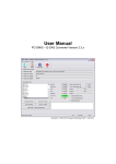
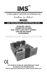
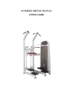
DBS USER MANUAL 10 Stern Avenue, Springfield, NJ 07081 Tel: 973-376-7400 Fax: 973-376-8265 TABLE OF CONTENTS SECTION I ......................................................................................................................1 Introduction ..........................................................................................................1 SECTION II .....................................................................................................................2 Processor Overview .............................................................................................2 A. Hardware ............................................................................................2 1. Main Menu ..............................................................................3 2. Run Screen ..............................................................................4 3. Calibration Screen ...................................................................5 4. Data Handling .........................................................................6 SECTION III ....................................................................................................................7 Machine Operation...............................................................................................7 A. Start-Up ..............................................................................................7 1. Cable Connections ..................................................................7 2. Power-Up The Processor ........................................................7 B. Calibration ..........................................................................................8 1. Factory Calibration Method ....................................................9 SECTION IV....................................................................................................................11 Troubleshooting ...................................................................................................11 A. Problem/Cause/Solution ....................................................................11 1. Processor .................................................................................11 2. XY Stage .................................................................................11 3. Punch Mechanism ...................................................................11 4. Barcode ...................................................................................12 DBS Processor - Table of Contents Page i SECTION I INTRODUCTION The Hudson Dried Blood Spot Processor (DBS) links the barcode identification of a sample (a dried blood spot or other sample impregnated on paper) to a location in a micro-titer plate. After the micro-titer plate is processed, the assay results can easily be linked eliminating the chance of sample mis-identification. The operator loads the micro-titer plate into the plate holder and the operator then instructs the processor to move to the first well. The operator picks up a sample and positions the barcode under the scanner. When the barcode is read and recognized, the operator then positions the sample under the punch selecting the best part of the sample to be inserted into the plate well. When the spot is properly positioned, the operator will press the foot switch, activating the punch. The spot is automatically inserted into the plate well. The DBS automatically indexes the micro-titer plate to the next well location. The operator selects the next sample and follows the procedure described above. The operator repeats this cycle until the last well of the plate is completed, at which time, the result data is processed. At completion of the plate, the result data is written to a data file and archived to the computer’s hard drive. The result data includes the micro-titer plate id, date/time, and specimen bar code ids. The processor utilizes several means to avoid error: 1. The plate holder is cornered allowing the plate to be inserted in only one orientation. 2. The computer, communicating to the processor via RS-232, confirms a plate is loaded into the holder by monitoring a sensor located internal to the plate holder. 3. The computer monitors a sensor (located on the punch mechanism) to insure the punch has returned to its up position. DBS Processor Page 1 SECTION II PROCESSOR OVERVIEW A. Hardware Part Name Part # Peripheral Equipment footswitch (1) ................................842-6091 computer cables (1) ......................83F888 AC line cord (1) ............................ELC-1009 Barcode Hand held scanner (1) ....................LS1006-I000-1900Z Punch and Die die plate (1) ...................................A1578 punch (1) .......................................A2431 punch holder (1)…………………..A2430 X-Y Stage lead screw shaft (2) .......................SPM4-3708-10.4375 lead screw nut (2) .........................TAB4-3708M brg support unit (2) .......................B6-01 linear guide (4) .............................SR20V2UU+280L-II Electrical photosensor (6) .............................EE-SX671 limit switch (1) .............................ELC-1025 indexer/driver (2) ..........................IM483I driver power supply (1) ................IP404 I/O power supply (1) .....................800-9756 rocker switch (1) ...........................ELC-1019 fuse (1) ..........................................10 amp fuse (1) ...........................................2 amp fuse (1) ...........................................3 amp motor……………………………..M2-2220-S interface board……………………OTP4-232 DBS Processor Page 2 B. Software 1. Main Screen The Dried Blood Spot Testing System boots up to display its main screen as show below. The main screen provides the following available selections: This button begins a run using a new destination plate. See below for more information on processing plates. This button will display the calibration dialog where a user can adjust the positioning of the DBS. See below for more information on calibrating. This button displays a history of all plates stored in the system and allows the user to select plates to view or delete. This button displays a history of all plates stored in the system and allows the user to select plates to export to a text file. This button allows the user to change which RS232 ports are used for communication with the DBS and the barcode scanner. DBS Processor Page 3 This button allows the user to change the start and stop wells for the run as well as the order in which wells are processed. 2. Run Screen Once the user selects to start a run, they will be prompted to scan the destination plate barcode using the hand scanner, or to enter the barcode using the keyboard. After scanning the destination plate barcode, the user is prompted to load the plate into the DBS unit. The unit will confirm that the plate has been loaded correctly and will then move to the starting well. The user is then prompted to scan the sample barcode using the fixed barcode scanner. Once the barcode has been scanned, the user is prompted to press the foot switch to activate the punch. The DBS unit then moves to position the next well under the punch. These steps are repeated until the DBS reaches the stop well. After the last well is punched, or if the user clicks Cancel on either the scan or punch prompts, the screen will appear as shown below. The plate map depicts a grid of all the well locations, A1 thru H12. Each well displays the sample barcode scanned for each well. The user can double-click any well from the current run to punch or re-punch that well. Wells not normally used during a run will be grayed-out and may not be punched. The user can click the Finish Plate button to complete the plate and save the data in the database. If the user clicks the Abort Plate button, the data will be discarded. DBS Processor Page 4 3. Calibration Screen The calibration screen displays a plate map indicating the calibration points for a microtiter plate, and the movement tools useful in calibrating the processor. The calibration screen is password protected upon entry. For proper positioning of the micro-titer plate, it must be calibrated. To assist in calibration of the plate, the Jog Intervals, Jog Arrows, and Current Position displays are used. Selecting a well on the plate diagram will allow the user to move to the selected position. Selecting the Cleaning Position or Load Position buttons will allow the user to move to one of these locations. Once a location is selected, the user can jog the DBS unit using the Jog Arrows. The current location can be saved by pressing the Save Point button. The Home button is used to instruct the XY stage to find its home position. The Test Punch button will activate the punch. DBS Processor Page 5 The Calculate Plate button will recalculate all well positions based on the calibrated locations of wells A1, A12, H1, and H12. The Move To Point button moves to the currently selected point. The Halt Motion button stops any motion of the DBS unit. 4. Data Handling During a run data about the current plate and its samples is stored in a temporary location in the system database. This allows a plate to be completed after a power outage or other system failure. When a plate has been completed and the operator selects “Finish Plate” from the run screen, the data is permanently saved in the system database. The following data is stored for each plate: A unique ID for the plate. The destination plate barcode. The date and time the run was started. The intended starting well. The intended ending well. The total wells on the plate. The order in which the wells were intended to be punched. (Column or Row) Whether or not the run was a simulated or actual run. The following data is stored for each sample: A unique ID for the sample. The unique ID of the destination plate. The well into which the sample was punched. The sample barcode. DBS Processor Page 6 SECTION III Machine Operation A. Start-Up 1. Cable Connections Computer - connect the computer power cable. Mouse - connect the mouse cable to the computer backpanel. Keyboard – connect the keyboard cable the the PS/2 port on the handheld scanner Computer Monitor (optional) - connect the monitor communications cable to the computer; plug monitor to wall outlet. USB to RS232 Converter (optional) – connect the USB converter to the computer using the supplied USB cable. Footswitch - connect the 4 pin plug on the footswitch cable to the 4 pin receptacle marked “Footswitch” on the processor back panel. Stationary Barcode - using the supplied serial cable, connect the 9-pin female to an RS232 port on the computer or the optional USB to RS232 converter. Hand-Held Barcode - using the supplied barcode reader cable, connect one end of the cable to the computer's keyboard input port and plug the keyboard into the other end. Controller - using the supplied serial cable, connect the 9-pin female to an RS232 port on the computer or the optional USB to RS232 converter. AC Power - using the 3 conductor detachable line cord, connect the female end to the connector marked “AC Power” on the processor back panel. Pneumatic - using the ¼-inch quick-connect fitting on the processor back panel, run a flexible ¼-inch air line from a source of clean, dry air rated at 80-100 psi. This air is required to power the punch. 2. Power-Up The Processor Step 1: Connect all cables as outlined in Section III.A.1. DBS Processor Page 7 Step 2: Plug the 3 prong computer power cable into the AC wall outlet. Step 3: Plug the 3 prong processor power cable into the AC wall outlet. At this time all cables should be properly connected! Step 4: Power-up the processor by flipping the switch located on the front of the processor. Note, if done correctly, the green switch LED should turn on. Step 5: Power-up the computer by pushing in the power button located on the front of the computer. Note, if done correctly, the power LED’s located on the front of the computer should come on and the computer should begin to boot-up. Step 6: Power-up the computer monitor by flipping the switch located on the back of the monitor. Note, if done correctly, the power LED located on the front of the monitor should come on. Step 7: Confirm the computer has boot-up properly. The monitor should display the Main Screen. Step 8: Confirm the computer and processor are communicating. The Punch Unit Status on the Main Screen should display the firmware version of the unit. Step 9: With confirmation of Step 7 and 8, the operator is ready to begin. B. Calibration To proper position the micro-titer plate, the DBS Processor utilizes a four (4) point calibration technique. The calibration technique relies on the operator to calibrate, and set the position, of four out of the ninety-six wells in the micro-titer plate. The calibration wells are A1, A12, H1, and H12. The DBS processor should be calibrated in order to accurately position the micro-titer plate. The equipment has been factory calibrated and no further calibration should be necessary. There is no one method of calibration which is best. The actual calibration technique may differ from calibrator to calibrator, depending on the results and method most liked by the individual. The method most used by the factory is: DBS Processor Page 8 1. Factory Calibration Method Step 1: Properly connect all cables and power-up the machine as described in Sections III.A.1 and III.A.2, respectively. Step 2: From the Main Screen, enter the Calibration Screen by selecting “Calibrate”. This function is password protected. Step 3: Press the Home button to home the XY stage. Step 4: The operator should prompt the XY stage to move to the load position. Step 5: Load a micro-titer plate. Step 6: The operator should prompt the XY Stage to move to well A1. Step 7: Remove the punch mechanism front panel. Step 8: The operator can slide open the clear lexan door so as to have a clear view of the micro-titer plate. Step 9: Loosen the two punch pin clamp screws. The punch is now free to move freely in and out of the microtiter wells. Caution must be exercised not to move the table with the punch down. Note: a small piece of thin cardboard can be used to hold the punch up. Step 10: If the punch tool enters the well without interference, then the operator should set this location by clicking the Save Point button. Step 10a: If the punch tool does not enter the well without interference, and/or if the XY stage is not in the proper position under the punch tool, then the operator should reposition the XY stage so that the punch tool enters the well without interference. The operator can reposition the XY stage using the Jog Interval and Jog Arrows. Use the Jog Interval to set the magnitude of the jog amount (distance you wish to move with each jog). Use the Jog Arrows to jog the XY stage in either plus or minus X or Y direction until the XY stage is properly positioned with the calibration well directly under the punch. Note: the XY stage will move when a jog arrow is activated. Once the XY stage is in the proper position, set this location as described in Step 10 above. Note: The XY Position Display may be helpful to the operator to determine the approximate magnitude of the jog interval required for the move. Step 11: The operator should repeat this procedure for wells A12, H1, and H12. Step 12: When all four (4) calibration points are set. The operator should press the Calibrate Plate button. The operator will be prompted to recalculate all well DBS Processor Page 9 positions. To re-calibrate the remaining plate wells and save all calibration data, select Yes. DBS Processor Page 10 SECTION IV Troubleshooting A. Problem/Cause/Solution 1. Processor DBS rocker switch does not light when switched on. Cause: No power to the DBS. Solution: Check power cord on back of unit. Check the Main Screen shows the firmware version of the punch unit. If the firmware version is displayed, the rocker switch is defective and should be replaced. If “Offline”, check all cabling and proper connections, and check Fuse 1 on the processor back panel. If Fuse 1 is blown, replace Fuse 1. DBS rocker switch is lighted, but the computer screen shows the punch “OFFLINE” Cause: The computer is not communicating with the DBS controller. Solution: Check the connections between the computer and the DBS unit. Check to be sure that the correct serial port for the RS-232 connection has been selected. 2. XY Stage Plate nest does not index properly. Cause: Mis-alignment between plate and punch. Solution: Check to see that the plate is seated properly in the nest. Check the plate is properly calibrated. 3. Punch Mechanism Punch won’t activate when footswitch is pressed. Cause: No communication/footswitch not plugged in/fuse has blown. Solution: If the plate has also stopped moving, check communication with the DBS as listed above under “Computer shows punch OFFLINE.” If the DBS operates properly in all other ways except for the punch, check if Fuse 2 on the processor back panel is blown. If so, replace Fuse 2. If the fuse is O.K., check footswitch operation. Punch does not cut cleanly. Cause: Punch is dull. Solution: The punch head should be replaced or sharpened. Punch does not retract properly. Cause: Paper is trapped in punch plate hole. DBS Processor Page 11 Solution: Clean punch and around punching area. 4. Barcode Barcode reader does not work. Cause: The computer is not communicating with the barcode reader. Solution: Check the connections between the computer and the DBS. Check to be sure that the correct serial port for the BARCODE connection has been selected. DBS Processor Page 12