1
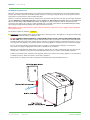
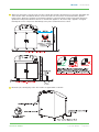
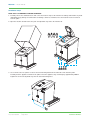
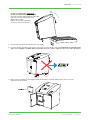
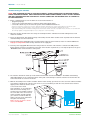
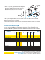
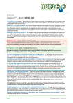
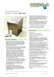
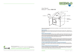
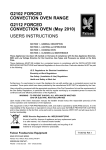
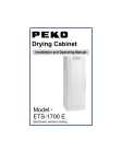
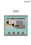
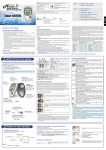
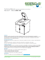
Technical Manual (includes Installation Instructions)
Waste20TM - Model W20.180
General
Best practice dictates the removal of food waste quickly and completely from commercial kitchens, eliminating
unpleasant odours and spillages, and the risk of contaminating fresh or uncooked food. Waste20TM facilitates the efficient,
safe and hygienic removal of preparation waste, plate scrapings, out-of-date produce, and unwanted cooked items.
Waste20TM will process soft, organic food waste.
Electrical connections
Any modifications to the electrical supply must be carried out by a qualified electrician in accordance with the IEE Codes
of practice.
Replacement of the power cord must be carried out by Tony Team, or Tony Team’s service agent.
The mains socket should be installed in an accessible area close to the equipment to enable disconnection.
Product conformity
The Waste20TM W20.180 conforms to the Machine Safety Directive 89/392/EEC as amended by 91/368/EEC and 93/44/EEC.
Waste20TM also conforms to the protection requirements of the Electro Magnetic Compatibility Directive 89/336/EEC and
is manufactured in accordance with harmonized standards EN 50-014-1 Generic Emission and EN 50-014-2 Generic
immunity. Waste20TM also meets the requirements of the Low Voltage Directive 2006/95/EC.
Warranty
Waste20TM is supplied with a one year parts and labour warranty subject to:
1. Correct usage as detailed in the user manual
2. Correct installation as detailed in this manual
3. Tony Team’s standard terms and conditions for Waste20 TM
Spare parts
Spare parts are available from Tony Team 0044 (0)1629 813859 [email protected]
TECHNICAL MANUAL
Tony Team: 02/2013
l
Page 1 of 7
Waste20TM - Model: W20.180
Installation requirements
Waste20TM Commercial Food Waste Digester is designed for installation on a firm flat surface in a well-ventilated indoor
location. The machine must not be installed outside, it must be covered by a fully rain-proof shelter and protected from
temperatures no lower than 5°C and no higher than 40ºC.
Good access must be provided to allow the machine lid to open and for the operator to be able to work safely around the
machine. Minimum recommended wall gap to rear of appliance is 90mm. Allow reasonable space for an engineer to
also access the sides of the machine for service. The appliance must be installed so that the reset buttons and
emergency stop switches are easily accessible. Installation in a room with a floor drain is ideal. W20.180 weighs 230 Kg
when empty, and approximately 275 Kg when fully loaded with food waste.
NB: Installation must be carried out in accordance with local authority requirements. Water supplies require appropriate
back flow prevention.
The machine requires the following 3 services:
1. Continuous (24-hour) warm water supply at 50°C between 2-5 bar pressure. The appliance is designed to work using
water with a maximum hardness of 70mg per litre.
DO NOT CONNECT THE APPLIANCE TO A COLD WATER SUPPLY OR TO A SUPPLY THAT COULD RUN COLD
AT ANY TIME. If necessary, install a localised dedicated water heater specifically to continuously feed the Waste20TM.
A minimum 3Kw water heater with a 50-litre storage capacity is required. Install the localised water heater as close to
the inlet point of the appliance as possible. Do not connect other appliances or fittings to the hot or warm water supply.
The use of a thermostatically-controlled mixer valve to provide a controlled blended supply is recommended.
Tony Team can supply an appropriate mixing valve at additional cost if required.
Waste20TM uses approximately 0.6m3 water per 24 hours, and 2.6 litres in a 30-second period when the spray jets are
running, with a 7-minute recovery time. 2 bar (30 PSI) minimum pressure is required, 5 bar (75 PSI) maximum.
Install a local isolation valve. Insulation of the pipework between the water heater and the appliance is recommended
to minimise heat loss. Flush clean before connecting to appliance.
Ensure there is no danger of the water temperature setting being altered by unauthorised users.
Tony Team: 02/2013
l
Page 2 of 7
TECHNICAL MANUAL
Waste20TM - Model: W20.180
2. 42mm (11/2-inch) waste connection. Do not reduce. Ideally this should be discharged to an open floor drain within 2m
of the machine outlet. A maximum distance of 3m to the main soil connection is recommended with a gradient
between 2-9%. Drain lines should be cleaned before appliance connection. Drain is pump assisted, but will not run
uphill. Run an independent drain line. Do not tee in with other appliances. Do not fit a trap – appliance is trapped
internally. Do not use compression drain fittings as the joints could fail and cause a flood.
3. Electrical 3-pin, 10-amp plug socket. The machine is supplied with a 1.5m flex.
TECHNICAL MANUAL
Tony Team: 02/2013
l
Page 3 of 7
Waste20TM - Model: W20.180
Installation steps
NOTE: THIS IS A MINIMUM 2-PERSON OPERATION
1. Carefully remove the cardboard sleeve that covers the machine. Inspect the machine for damage and inform Tony Team
immediately if any damage is found. Claims for damage cannot be entertained once the machine has been removed
from the pallet.
2. Open the machine lid and remove the pack of 4 adjustable legs. Close the machine lid.
3. Use a 17mm socket or spanner to remove the 4 transit fixing bolts from the underside of the machine pallet.
Carefully slide the appliance forward on the pallet so that the appliance edge overhangs by approximately 200mm.
Tighten two of the four adjustable legs into the transit bolt fixing holes.
Tony Team: 02/2013
l
Page 4 of 7
TECHNICAL MANUAL
Waste20TM - Model: W20.180
Carefully TILT APPLIANCE FROM BASE.
DO NOT LIFT MOULDED APPLIANCE TOP
and slide out pallet. Tighten final two adjustable
legs to the rear transit bolt fixing holes.
Gently lower machine.
Dispose of the pallet responsibly,
or return to Tony Team for reuse.
5. Peel off the plastic protective film from the outer panels.
6. Level the machine in position and connect to the services as described in this manual. Minimum recommended wall
gap to rear of appliance is 90mm. Allow reasonable space for a service engineer to also access the side panels.
7. Place a 5L box of Waste20TM fluid (supplied with the machine) in the fluid chamber and connect as per the
instructions on the fluid box.
TECHNICAL MANUAL
Tony Team: 02/2013
l
Page 5 of 7
Waste20TM - Model: W20.180
Commissioning the machine
NOTE: HAVE A MINIMUM OF 5KG OF FOOD WASTE READY. DO NOT COMMISSION THE MACHINE WITHOUT
HAVING FOOD WASTE READY. ONCE THE MACHINE HAS BEEN COMMISSIONED, IT MUST BE LEFT RUNNING
AND MUST BE REGULARLY FED FOOD WASTE. DO NOT COMMISSION THE MACHINE UNTIL IT IS READY TO
BE USED REGULARLY.
1. Before commissioning, be sure the drains are clear and the machine is:
- plugged in properly.
- connected to a 24/7 uninterrupted, continuous warm water (50ºC) supply.
- connected to drains as per one of the two options in the Installation Instructions.
42mm (1 1/2-inch) waste connection. Do not reduce. Ideally this should be discharged to an open floor drain within 2m of the machine outlet.
If this is not possible, a maximum distance of 3m to the main soil connection is recommended with a gradient between 2-9%.
Only swept waste fittings with a maximum of 4 fittings between the machine and the soil & vent or floor drain. Ensure connection is to foul water drain.
Do not fit trap. Appliance is trapped internally. Do not use compression or short waste fittings.
2. Open the machine lid and remove the 3 bags of woodchips from the chamber. Check that nothing has been left
inside the chamber.
3. Pierce the plastic bags and empty all 3 bags of woodchips and the water-soluble sachet of powder into the machine
chamber. Firmly close the machine lid.
4. Turn the warm water supply ON, and if a localised water heater has been installed, ensure it is switched ON and is
fully up to temperature. Draw off any cold water in the supply line.
5. Turn the power supply ON. Ensure that the rotary isolator on the front of the machine is turned to the ON position.
Ensure that the emergency stop button on the front of the machine is pulled out (i.e. not depressed). Press the green
‘RESTART’ button on the machine’s control panel.
6. The machine will start in ‘warm up’ mode and the lid will remain locked for 20 minutes. The ‘WAIT’ and ‘Running’
lights will illuminate on the control panel. Note: It may take a few attempts to start the machine for the first time due
to the initial inrush of current to the motor.
7. With the woodchips in the machine chamber and the motor running, open the door to the electronic cabinet and make
sure that the red light on the current sensor is not on, or is not flickering on and off. If it is, this will cause nuisance
tripping of the shot bolt, and the current
sensor needs to be tuned.
If the red light is on, or is flickering
while the motor is running, use a
small electrical screwdriver and turn
the centre dial of the current sensor
slowly clockwise until the red light
goes out. Do not turn the dial any
further, only tune to the point where
the light is not flickering.
Make sure the electronics cabinet
door is left LOCKED.
Tony Team: 02/2013
l
Page 6 of 7
TECHNICAL MANUAL
Waste20TM - Model: W20.180
8. Remove the fascia plate covering the fluid chamber and check the
pressure / temperature gauge to ensure that water is being delivered at
between 45 - 50°C at 2 bar pressure. If this is not the case, adjust the
site services to suit. The pressure reducing valve built into the
Waste20TM is factory set at 2 bar. Replace the fascia panel
and close the fluid cabinet door.
9. After 20 minutes the machine will switch to normal operating condition, and is ready to receive food waste. The
‘WAIT’ light will extinguish and the machine lid will unlock.
10. Add the food waste and close the machine lid.
11. Pass this manual and the user manual and keys to the operator and inform them that the machine is now operational.
If you are unsure about any part of this operation, contact Tony Team +44 (0)1629 813859.
Planned Preventative Maintenance (PPM)
The Waste20TM machine should provide many years of trouble free service, as long as it is operated responsibly as
detailed in the User Manual. Below is a list of the recommended PPM operations and the approximate cycle times for
some of the component parts. Please note that these are only approximations and parts may last longer, or need
replacing sooner. Waste20TM is supplied with a 12-month parts and labour warranty. Operational procedure documents are
available for each of the PPM operations listed below.
FREQUENCY OF MAINTENANCE OPERATION
MAINTENANCE
OPERATION
Up to
As
6
12
24
36
48
60
120
required Monthly Monthly Monthly Monthly Monthly Monthly Monthly
SERVICE *
SHEET
Change fluid box
X
Remove non organic material
X
X
Clean filter strainer
X
X
6
Clean spray nozzle heads
X
X
1&2
See 5L Fluid Box
Top up woodchip
See User Manual
X
Adjust wiper blades
14
X
Grease bearings
15
X
Flush drain pump
8
X
Replace drain pump
X
Replace pressure switch
X
19
18 - 18F
17
Replace gas strut
X
16
Replace wiper blades
X
15
Replace fluid box springs
X
5
Replace drive belt
X
9
Replace lid seal
X
16
Replace spray pump
X
3
Replace bearings
X
10 - 10A
Replace incoming water assembly
X
Replace motor & gearbox
6 Monthly Service
12 Monthly service
TECHNICAL MANUAL
12
X
11
*Service sheets are available from Tony Team - Tel: +44 (0)1629 813859
Preventative Maintenance Service can be purchased as an optional extra available from Tony Team:
Part No: W20.PMS (includes 2 site visits 6-mth/12-mth, with Annual Re-Charger Pack)
Tony Team: 02/2013
l
Page 7 of 7
Unit 6, Station Road, Bakewell,
Derbyshire DE45 1GE.
Tel: 01629 813859 Fax: 01629 814334
Email:[email protected]
www.tonyteam.co.uk
Total Waste Handling Solutions for a Better Environment
Expertise and innovation
Tony Team's enviable reputation has been built on excellence of product quality
backed-up by the highest levels of customer service. For over 30 years we have
been sharpening the leading edge of compactor and baling technology to bring
you the most reliable and cost-effective waste management solutions.