1
ACCE L E NS (ACS ) CANo pe n
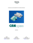
Accelens (ACS) Inclinometer With CANopen Interface
User Manual
AMERICAS
FRABA Inc.
1800 East State Street, Suite 148
Hamilton, NJ 08609, USA
T +1 609 750-8705, F +1 609 750-8703
www.posital.com, [email protected]
EUROPE
POSITAL GmbH
Carlswerkstrasse 13c
D-51063 Köln, GERMANY
T +49 221 96213-0, F +49 221 96213-20
www.posital.eu, [email protected]
1 of 45
ASIA
FRABA Pte. Ltd.
60 Alexandra Terrace,
#02-05 The Comtech, SINGAPORE 118502
T +65 6514 8880, F +65 6271 1792
www.posital.sg, [email protected]
ACCE L E NS (ACS ) CANo pe n
Table Of Contents
GENERAL SECURITY ADVISE ......................................................................................................................... 4
ABOUT THIS MANUAL.................................................................................................................................. 4
1. INTRODUCTION ........................................................................................................................................ 5
1.1 ACCELENS (ACS)................................................................................................................................... 5
1.2 CANOPEN INTERFACE ............................................................................................................................... 6
1.3 ACS- CANOPEN ...................................................................................................................................... 6
1.4 TYPICAL APPLICATIONS OF ACS................................................................................................................... 7
2. MODES, PARAMETERS AND OBJECTS...................................................................................................... 8
2.1 OPERATING MODES.................................................................................................................................. 9
2.2 TRANSMISSION MODES ........................................................................................................................... 10
2.3. PROGRAMMABLE PARAMETERS................................................................................................................ 11
3. INSTALLATION ........................................................................................................................................ 13
3.1 ACCESSORIES REQUIRED .......................................................................................................................... 13
3.2 PIN ASSIGNEMENT ................................................................................................................................. 13
3.3 INSTALLATION PRECAUTIONS .................................................................................................................... 13
3.4 MOUNTING INSTRUCTIONS ...................................................................................................................... 14
3.6 MEASUREMENT AXES ............................................................................................................................. 15
4.ACS SOFTWARE CONFIGURATION.......................................................................................................... 16
4.1 IMPORTANT FACTORY SETTINGS ................................................................................................................ 16
4.2 ACTIVE PROGRAMMING OBJECTS .............................................................................................................. 16
4.3 BOOT-UP PROCEDURE............................................................................................................................. 17
4.4 PDO TRANSMISSION.............................................................................................................................. 18
4.5 EXPLICIT EXCHANGES (SDO) .................................................................................................................... 20
5. WORKING WITH SCHNEIDER PLC........................................................................................................... 21
5.1 INTRODUCTION ...................................................................................................................................... 21
5.2 NETWORK INITIALIZATION ........................................................................................................................ 21
5.2.1 HARDWARE........................................................................................................................................ 21
5.2.2- SOFTWARE PROJECT INFORMATION ....................................................................................................... 22
5.3 CONFIGURATION .................................................................................................................................... 25
5.4 DEBUGGING .......................................................................................................................................... 27
5.4 RUN .................................................................................................................................................... 29
7. TROUBLESHOOTING .............................................................................................................................. 32
APPENDIX A: ACS CANOPEN OBJECTS ....................................................................................................... 33
APPENDIX B: ORDERING CODE .................................................................................................................. 41
GLOSSARY................................................................................................................................................... 42
AMERICAS
FRABA Inc.
1800 East State Street, Suite 148
Hamilton, NJ 08609, USA
T +1 609 750-8705, F +1 609 750-8703
www.posital.com, [email protected]
EUROPE
POSITAL GmbH
Carlswerkstrasse 13c
D-51063 Köln, GERMANY
T +49 221 96213-0, F +49 221 96213-20
www.posital.eu, [email protected]
2 of 45
ASIA
FRABA Pte. Ltd.
60 Alexandra Terrace,
#02-05 The Comtech, SINGAPORE 118502
T +65 6514 8880, F +65 6271 1792
www.posital.sg, [email protected]
ACCE L E NS (ACS ) CANo pe n
APPENDIX A: ACS CANOPEN OBJECTS ....................................................................................................... 33
OBJECT 1000H: DEVICE TYPE ........................................................................................................................ 33
OBJECT 1001H: ERROR REGISTER ................................................................................................................... 34
OBJECT 1003H: PRE-DEFINED ERROR FIELD ..................................................................................................... 34
OBJECT 1005H: COB-ID SYNC ...................................................................................................................... 34
OBJECT 1008H: MANUFACTURER DEVICE NAME ............................................................................................... 35
OBJECT 1009H: MANUFACTURER HARDWARE VERSION ..................................................................................... 35
OBJECT 100AH: MANUFACTURER SOFTWARE VERSION ...................................................................................... 35
OBJECT 100CH: GUARD TIME........................................................................................................................ 35
OBJECT 100DH: LIFE TIME FACTOR................................................................................................................. 35
OBJECT 1010H: STORE PARAMETERS .............................................................................................................. 35
OBJECT 1011H: RESTORE PARAMETERS ........................................................................................................... 36
OBJECT 1016H: CONSUMER HEARTBEAT TIME.................................................................................................. 36
OBJECT 1017H: PRODUCER HEARTBEAT TIME................................................................................................... 37
OBJECT 2200H: CYCLIC TIMER ....................................................................................................................... 37
OBJECT 2300H: SAVE PARAMETER WITH RESET................................................................................................. 37
OBJECT 2600H: PRESET (1) X/Z-AXIS............................................................................................................... 37
OBJECT 2601H: PRESET (1) VALUE Y-AXIS ........................................................................................................ 37
OBJECT 3000H: NODE NUMBER (2) ................................................................................................................. 38
OBJECT 3001H: BAUDRATE (3) ....................................................................................................................... 38
OBJECT 3100H: MOVING AVERAGE FILTER....................................................................................................... 38
OBJECT 3200H: EXPONENTIAL FILTER.............................................................................................................. 38
OBJECT 6000H: RESOLUTION ........................................................................................................................ 39
OBJECT 6010H: POSITION VALUE X/Z-AXIS ..................................................................................................... 39
OBJECT 6011H: INVERSION/SCALING X/Z-AXIS ................................................................................................ 39
OBJECT 6012H: PRESET (1) X/Z-AXIS............................................................................................................... 40
OBJECT 6013H: OFFSET X/Z-AXIS .................................................................................................................. 40
OBJECT 6020H: POSITION VALUE Y-AXIS ......................................................................................................... 40
OBJECT 6021H: INVERSION/SCALING Y-AXIS .................................................................................................... 40
(1)
OBJECT 6022H: PRESET Y-AXIS .................................................................................................................. 41
OBJECT 6023H: OFFSET Y-AXIS ..................................................................................................................... 41
AMERICAS
FRABA Inc.
1800 East State Street, Suite 148
Hamilton, NJ 08609, USA
T +1 609 750-8705, F +1 609 750-8703
www.posital.com, [email protected]
EUROPE
POSITAL GmbH
Carlswerkstrasse 13c
D-51063 Köln, GERMANY
T +49 221 96213-0, F +49 221 96213-20
www.posital.eu, [email protected]
3 of 45
ASIA
FRABA Pte. Ltd.
60 Alexandra Terrace,
#02-05 The Comtech, SINGAPORE 118502
T +65 6514 8880, F +65 6271 1792
www.posital.sg, [email protected]
ACCE L E NS (ACS ) CANo pe n
I nc li n om e ter
G en era l Sec ur i ty Ad vi se
Ab o u t T h i s M an ua l
Important Information
Background
Read these instructions carefully, and have a look
This user manual explains how to install and
at the equipment to become familiar with the
configure the following ACS inclinometer with
device before trying to install, operate, or maintain
CANopen
it.
Schneider TWIDO PLC.
The following special messages may appear
Relate Note
throughout this documentation & on the equipment
Version date: 28 October, 2010
to warn of potential hazards or to call attention
Version number: 1.0
towards
Document Name:
information
that
clarifies/simplifies
a
interface
with
illustrations
from
a
ACS_CANOpen Manual_20101028.pdf
procedure.
The addition of this symbol to a
Imprint
Danger or Warning safety label
indicates that an electrical hazard
FRABA PTE LTD
60 Alexandra Terrace,
exists, which will result in personal
injury if the instructions are not
#02-05 The Comtech, SINGAPORE 118502
T +65 6514 8880
followed.
F +65 6271 1792
This is the safety alert symbol. It is
Copyright
used for alerting, in case of potential
© FRABA N.V., all rights reserved - Claims
personal injury or hazards. Obey all
copyright on this documentation. It is not allowed to
safety messages that follow this
modify, extend, or hand over to a third party and to
symbol to avoid possible injury or
copy this documentation without written approval
death
by FRABA PTE LTD. Nor is any liability assumed
Please Note
for damages resulting from the use of the
Electrical equipment should be serviced only by
information
qualified personnel. No responsibility is assumed
publication and features described herein are
by POSITAL for any consequences arising out of
subject to change without notice.
contained
herein.
Further,
this
the use of this material. This document is not
intended as an instruction manual for untrained
User Annotation
persons.
All readers are highly welcome to send us
feedback and comments about this document. You
can reach us by e-mail at [email protected]
AMERICAS
FRABA Inc.
1800 East State Street, Suite 148
Hamilton, NJ 08609, USA
T +1 609 750-8705, F +1 609 750-8703
www.posital.com, [email protected]
EUROPE
POSITAL GmbH
Carlswerkstrasse 13c
D-51063 Köln, GERMANY
T +49 221 96213-0, F +49 221 96213-20
www.posital.eu, [email protected]
4 of 45
ASIA
FRABA Pte. Ltd.
60 Alexandra Terrace,
#02-05 The Comtech, SINGAPORE 118502
T +65 6514 8880, F +65 6271 1792
www.posital.sg, [email protected]
ACCE L E NS (ACS ) CANo pe n
I nc li n om e ter
1 . In tr o du c ti o n
This manual explains how to install and configure the ACS gravity referenced inclinometers (suitable for
industrial, military and heavy duty applications) with a CANopen interface. The products are fully compliant
with CANopen DS410 standards.
1.1 ACCELENS (ACS)
ACCELENS inclinometers sense and measure the angle of tilt (Inclination/Slope/Elevation) of an object
with respect to the force of gravity. The angle is measured with the relative change in electrical
capacitance.
The basic principle behind this ACS inclinometer is a Micro-Electro-Mechanical Systems (MEMS) sensor
cell that is embedded to a fully molded ASIC. A simplified version of the sensor consists of two electrodes,
one is fixed, and the other is flexible (connected with spring elements). When the inclinometer is parallel to
the surface of measurement, a corresponding capacitance is measured. If the sensor is tilted, the flexible
electrode will change its position relative to the fixed electrode. This results in a change of the capacitance
between the two electrodes which is measured by the sensor cell. The change of the capacitance is
converted to a corresponding inclination value.
The MEMS sensor cell in ACS consists of a micromechanical structure with an array of electrodes for
better accuracy. Under the influence of gravity, the distance between some electrodes change and this
distance can be detected by measuring the capacity between the electrodes, as explained above. This
technology is available in different grades and lower grades have entered mass markets like mobile
phones or tablet computers.
The ACS series of inclinometers are available in two variants. First, a single axis measurement variant with
a range of 0-360° ( either clockwise or anti-clockwise) and the other variant, a dual axis measurement
capable ACS model with a range of ±80°.
Absolute inclinometers identify all the points of a movement by means of an unambiguous signal. Due to
their capacity to give clear and exact values to all inclinations positions, inclinometers have become one of
the interesting alternatives to singleturn absolute (and incremental) encoders and a link between the
mechanical and control systems.
Benefits of ACS:
Small size
Cost efficient
AMERICAS
FRABA Inc.
1800 East State Street, Suite 148
Hamilton, NJ 08609, USA
T +1 609 750-8705, F +1 609 750-8703
www.posital.com, [email protected]
High Protection Class
EUROPE
POSITAL GmbH
Carlswerkstrasse 13c
D-51063 Köln, GERMANY
T +49 221 96213-0, F +49 221 96213-20
www.posital.eu, [email protected]
5 of 45
High Accuracy
Very robust
ASIA
FRABA Pte. Ltd.
60 Alexandra Terrace,
#02-05 The Comtech, SINGAPORE 118502
T +65 6514 8880, F +65 6271 1792
www.posital.sg, [email protected]
ACCE L E NS (ACS ) CANo pe n
1.2 CANopen Interface
CANopen is based on the Controller Area Network (CAN) that was developed by automotive industries in
the 80s and is nowadays used in many industrial applications. The application protocol CANopen was
introduced by the multi vendor association CiA to ensure a full compatibility of industrial automation
products. It is a multiple access system (maximum: 127 nodes), which means that all devices can access
the bus. These devices/nodes are the components of the CANopen bus and in our case the node is ACS.
In simple terms, CANopen works as a client-server model. Each device checks whether the bus is free,
and if it is free the device can send messages. If two devices try to access the bus at the same time, the
device with the higher priority level (lowest ID number) has permission to send its message.
Devices with the lowest priority level must cancel their data transfer and wait before re-trying to send their
message. Data communication is carried out via messages. These messages consist of a unique COB -ID
followed by a maximum of 8 bytes of data. The COB-ID, which determines the priority of the message,
consists of a function code and a node number. The node number corresponds to the network address of
the device. It is unique on a bus in order to distinguish nodes and prevent any conflict of interests.
The function code varies according to the type of message being sent:
Management messages (LMT, NMT)
Messaging and service (SDOs)
Data exchange (PDOs)
Predefined messages (Synchronization, Emergency messages)
1.3 ACS- CANopen
The ACS CANopen inclinometer corresponds to the class 2 inclinometer profile with DS 410 CANopen
standards, in which the characteristics of inclinometers with CANopen interface are defined. The ACS is
available in a completely molded and rugged plastic housing.
The ACS CAnopen series of inclinometers are available in two variants. First, a single axis measurement
variant with a range of 0-360° ( either clockwise or anti-clockwise) and the other variant, a dual axis
measurement capable ACS model with a range of ±80°.
In addition to high resolution, accuracy and protection class of IP69K it has in-built active linearization and
temperature compensation. This makes ACS suitable for rugged environments and versatile applications
in industrial, heavy duty and military applications.
AMERICAS
FRABA Inc.
1800 East State Street, Suite 148
Hamilton, NJ 08609, USA
T +1 609 750-8705, F +1 609 750-8703
www.posital.com, [email protected]
EUROPE
POSITAL GmbH
Carlswerkstrasse 13c
D-51063 Köln, GERMANY
T +49 221 96213-0, F +49 221 96213-20
www.posital.eu, [email protected]
6 of 45
ASIA
FRABA Pte. Ltd.
60 Alexandra Terrace,
#02-05 The Comtech, SINGAPORE 118502
T +65 6514 8880, F +65 6271 1792
www.posital.sg, [email protected]
ACCE L E NS (ACS ) CANo pe n
The inclinometer supports the following operating modes:
Polled mode: The position value is transmitted only on request.
Cyclic mode: The position value is sent cyclically (regular, adjustable intervals) on the bus.
SYNC mode: The position value is sent after a synchronization message (SYNC) is received. The
position value is sent every n SYNCs (n ≥ 1).
State change mode: The position value is transmitted whenever the position of the inclinometer,
in continuous operation changes.
The CANopen bus interface on these inclinometers permit speeds of up to 1Mbaud (30m cable for a
maximum speed of 1Mbaud, 5000 m cable for a maximum speed of 10 Kbaud).
The ACS-CANopen is a flexible measurement device. This is proved by the fact that it has easily
programmable parameters like Resolution, Preset
(1)
and software filters. Other functions such as offset
values, baud rate, and node number can also be configured using CAN objects in the ACS inclinometers
with ease and according to the network.
Various software tools for configuration and parameter-setting are available from different suppliers. It is
easy to align and program the inclinometers using the EDS (electronic data sheet) configuration file
provided.
1.4 Typical Applications of ACS
Cranes and Construction Machinery
Medical Systems
Elevated Platforms
Mobile lifts and Fire engines
Automated Guided Vehivles (AGV)
Automatic Assembling Machinery
Boring and Drilling Applications
Levelling and Flattening Machinery
AMERICAS
FRABA Inc.
1800 East State Street, Suite 148
Hamilton, NJ 08609, USA
T +1 609 750-8705, F +1 609 750-8703
www.posital.com, [email protected]
EUROPE
POSITAL GmbH
Carlswerkstrasse 13c
D-51063 Köln, GERMANY
T +49 221 96213-0, F +49 221 96213-20
www.posital.eu, [email protected]
7 of 45
ASIA
FRABA Pte. Ltd.
60 Alexandra Terrace,
#02-05 The Comtech, SINGAPORE 118502
T +65 6514 8880, F +65 6271 1792
www.posital.sg, [email protected]
ACCE L E NS (ACS ) CANo pe n
2 . M o de s, Param e te r s a nd Obj ec ts
The purpose of this chapter is to describe all the available configuration parameters of the ACS
inclinometers with a CANopen interface.
Before going into details the following information describes useful technical terms and acronyms for
CANopen network communication.
EDS File
EDS (Electronic Data Sheet)
An EDS file describes the communication properties of a device on the CAN
network (baud rates, transmission types, I/O features, etc.). It is provided by
the device manufacturer and is used in the configuration tool to configure a
node (like a driver in an operating system).
PDO
PDO (Process Data Object)
CANopen frame containing I/O data.
We distinguish between:
Transmit-PDOs (TPDOs with data provided by a node) &
Receive-PDOs (RPDOs with data to be consumed by a node).
The transmission direction is always seen from a node's point of view.
SDO
SDO (Service Data Object)
CANopen frames containing parameters. SDOs are typically used to read or
write parameters while the application is running.
COB-ID
COB-ID (Communication Object Identifier)
Each CANopen frame starts with a COB-ID working as the Identifier in the
CAN frame. During the configuration phase, each node receives the COBID(s) of the frame(s) for which it is the provider (or consumer).
NMT
Network Management Protocol
The NMT protocols are used to issue state machine change commands (i.e. to
start and stop the devices), detect remote device boot ups and error
conditions.
AMERICAS
FRABA Inc.
1800 East State Street, Suite 148
Hamilton, NJ 08609, USA
T +1 609 750-8705, F +1 609 750-8703
www.posital.com, [email protected]
EUROPE
POSITAL GmbH
Carlswerkstrasse 13c
D-51063 Köln, GERMANY
T +49 221 96213-0, F +49 221 96213-20
www.posital.eu, [email protected]
8 of 45
ASIA
FRABA Pte. Ltd.
60 Alexandra Terrace,
#02-05 The Comtech, SINGAPORE 118502
T +65 6514 8880, F +65 6271 1792
www.posital.sg, [email protected]
ACCE L E NS (ACS ) CANo pe n
2.1 Operating Modes
2.1.1 Mode: Preoperational
When the device is in this state, its configuration can be modified. However, only SDOs can be used to
read or write device-related data. The device goes into "Pre-Operational" state:
After the power up, or
On receiving the "Enter Pre-Operational" NMT indication, if it was in Operational state.
When configuration is complete, the device goes into one of the following states on receiving the
corresponding indication:
"Stopped" on receiving the "STOP REMOTE NODE" NMT indication,
"Operational" on receiving the "START REMOTE NODE" NMT indication.
To set a node to pre-operational mode, the master must send the following message:
Identifier
0h
Byte 0
80 h
Byte 1
00
0h
80 h
NN
Description
NMT-PreOp, all nodes
NMT-PreOp, NN
NN: node number
2.1.2 Mode: Start – Operational
The device goes into the "Operational" state if it was in the "Pre-Operational" state on receiving the "Start
Remote Node" indication. When the CANopen network is started using the "Node start" NMT services in
"Operational" state, all device functionalities can be used. Communication can use PDOs or SDOs.
NOTE: Modifications to the configuration in "Operational" mode may have unexpected consequences and
should therefore only be made in "Pre-Operational" mode.
To put one or all nodes in the start operational state, the master has to send the following message:
Identifier
Byte 0
Byte 1
Description
0h
01 h
00
NMT-Start, all nodes
0h
NN: node number
01 h
NN
NMT-Start, NN
AMERICAS
FRABA Inc.
1800 East State Street, Suite 148
Hamilton, NJ 08609, USA
T +1 609 750-8705, F +1 609 750-8703
www.posital.com, [email protected]
EUROPE
POSITAL GmbH
Carlswerkstrasse 13c
D-51063 Köln, GERMANY
T +49 221 96213-0, F +49 221 96213-20
www.posital.eu, [email protected]
9 of 45
ASIA
FRABA Pte. Ltd.
60 Alexandra Terrace,
#02-05 The Comtech, SINGAPORE 118502
T +65 6514 8880, F +65 6271 1792
www.posital.sg, [email protected]
ACCE L E NS (ACS ) CANo pe n
2.1.3 Mode: Stop – Operational
The device goes into the "Stopped" state on receiving the "Node stop" indication (NMT service) if it was in
"Pre-Operational" or "Operational" state. In this state, the device cannot be configured. No service is
available to read and write device-related data (SDO). Only the slave monitoring function ("Node
Guarding") remains active.
To put one or all nodes in the stop operational state, the master has to send the following message:
Identifier
Byte 0
Byte 1
Description
0h
02 h
00
NMT-Stop, all nodes
0h
NN: node number
02 h
NN
NMT-Stop, NN
2.1.4 Re-initialization of the Inclinometer
If a node is not operating correctly, it is advisable to carry out a reinitialization.
NN
Command
Index
Description
0h
82 h
00
Reset Communication
0h
NN: node number
81 h
NN
Reset Node
After reinitialization, the inclinometer accesses the bus in pre-operational mode.
2.2 Transmission Modes
Polled Mode
By a remote-transmission-request telegram the connected host calls for the
current process value. The inclinometer reads the current position value,
calculates eventually set-parameters and sends back the obtained process
value by the same identifier.
Cyclic Mode
The inclinometer cyclically transmits (without being called by the host) the
current process value. The cycle time can be programmed in milliseconds
for values between 1 ms and 65536 ms.
Sync Mode
After receiving a sync telegram by the host, the inclinometer answers with
the current process value. If more than one node number (encoder) shall
answer after receiving a sync telegram, the answer telegrams of the nodes
will be received by the host in order of their node numbers. The
programming of an offset-time is not necessary. If a node should not answer
after each sync telegram on the CAN network, the parameter sync counter
can be programmed to skip a certain number of sync telegrams before
answering again.
AMERICAS
FRABA Inc.
1800 East State Street, Suite 148
Hamilton, NJ 08609, USA
T +1 609 750-8705, F +1 609 750-8703
www.posital.com, [email protected]
EUROPE
POSITAL GmbH
Carlswerkstrasse 13c
D-51063 Köln, GERMANY
T +49 221 96213-0, F +49 221 96213-20
www.posital.eu, [email protected]
10 of 45
ASIA
FRABA Pte. Ltd.
60 Alexandra Terrace,
#02-05 The Comtech, SINGAPORE 118502
T +65 6514 8880, F +65 6271 1792
www.posital.sg, [email protected]
ACCE L E NS (ACS ) CANo pe n
2.3. Programmable Parameters
Objects are based on the CiA 410 DS V1.2: CANopen profile for inclinometer (www.can-cia.org).
The following table gives the list of command identifiers sent and received by the inclinometer. These are
the standard commands used for communication and transmission between a master and slave in the
CAN bus. It is very useful when we study the communication logs between the master and slave and for
better understanding of the system under observation.
Command
Function
Telegram
Description
22h
Domain Download
Request
Parameter to inclinometer
60h
Domain Download
Confirmation
Parameter received
40h
Domain Upload
Request
Parameter request
43h, 4Bh, 4Fh (*)
Domain Upload
Reply
Parameter to Master
80 h
Warning
Reply
Transmission error
Table 1: Command Description
(*)The value of the command byte depends on the data length of the called parameter.
Command
Data length
Data length
43h
4 Byte
Unsigned 32
4Bh
2 Byte
Unsigned 16
4Fh
1 Byte
Unsigned 8
Table 2: Data Length of Commands
The following list of objects is the most frequently used objects while programming the CANopen ACS
inclinometer. The whole list of objects is available in Appendix A.
The objects 6010h and 6020h are used to get the inclination positions
POSITION VALUE
(Objects 6010h, 6020h)
from ACS080 in the range of ±80° and the object 6010h is used to get the
inclination position from ACS360 in the range of 0 - 360°.
These objects are used to store any re-configured parameters. Object
STORE PARAMETERS
(Objects 1010h, 2300h)
1010h just stores the parameters whereas 2300h saves the parameters
with a reset on storing it.
AMERICAS
FRABA Inc.
1800 East State Street, Suite 148
Hamilton, NJ 08609, USA
T +1 609 750-8705, F +1 609 750-8703
www.posital.com, [email protected]
EUROPE
POSITAL GmbH
Carlswerkstrasse 13c
D-51063 Köln, GERMANY
T +49 221 96213-0, F +49 221 96213-20
www.posital.eu, [email protected]
11 of 45
ASIA
FRABA Pte. Ltd.
60 Alexandra Terrace,
#02-05 The Comtech, SINGAPORE 118502
T +65 6514 8880, F +65 6271 1792
www.posital.sg, [email protected]
ACCE L E NS (ACS ) CANo pe n
The parameter resolution per 1 degree is used to program the desired
RESOLUTION PER 1°
(Object 6000h)
number of steps per revolution. The values 1, 10, 100, and 1000 can be
programmed.
The Preset value is the desired position value, which should be reached
(1)
PRESET VALUE
(Objects 6012h / 6013h)
at a certain physical position of the axis. The position value is set to the
desired process value by the parameter pre-set.
(3)
BAUDRATE
(Object 3001h)
The Baud rate can be programmed via SDO (default 20Kbaud).
The setting of the node number is achieved via SDO-Object. Possible
(valid) addresses lie between 0 and 96 but each address can only be
NODE NUMBER
(Object 3000h)
(2)
used once. The CANopen inclinometer adds internal 1 to the adjusted
device address. For inclinometers programmed via SDO, the default
is 20Hex = Node Number 32
FILTERS
(Objects 3100h/3200h)
OPERATING
PARAMETER
(Object 6011h)
Filters can be used to adjust the frequency of measurements and
calculation of position values.
The operating parameter sets the counting direction (i.e. inversion or
complement) and scaling of the measuring range.
Appendix A has a detailed list of all the objects that can be programmed with ACS CANopen. The
data type, data size, default value, r/w access definition and all sub-indexes are mentioned in it. It is
necessary to read the appendix A for clear knowledge before programming.
AMERICAS
FRABA Inc.
1800 East State Street, Suite 148
Hamilton, NJ 08609, USA
T +1 609 750-8705, F +1 609 750-8703
www.posital.com, [email protected]
EUROPE
POSITAL GmbH
Carlswerkstrasse 13c
D-51063 Köln, GERMANY
T +49 221 96213-0, F +49 221 96213-20
www.posital.eu, [email protected]
12 of 45
ASIA
FRABA Pte. Ltd.
60 Alexandra Terrace,
#02-05 The Comtech, SINGAPORE 118502
T +65 6514 8880, F +65 6271 1792
www.posital.sg, [email protected]
ACCE L E NS (ACS ) CANo pe n
3 . In stal la tio n
3.1 Accessories Required
Article No
Article
Description
ACS360/080
Inclinometer
ACS series of Inclinometers
DK-CA
EDS-File*
Disc containing EDS file for configuration
UMUS-CA
User Manual*
Installation and Configuration User Manual (English)
34050515
PAM5
Female cable counterconnector M12x1 5pin A-coded
10001978
PAM5 2m
Connecting cable PAM5 2m shielded
TR-B
Terminal Resistor
External terminal resistors for higher baud rate transmissions
* The documentation and the EDS file can be downloaded from our website http://www.posital.sg/
3.2 Pin Assignement
The inclinometer is connected via a 5 pin round M12 connector.
(Standard M12, Male side at sensor, Female at connector counterpart
Or connection cable).
Signal
5 pin round connector pin number
Open Cable
CAN Ground
1
Green
24 V supply voltage
2
White
0 V supply voltage
3
Brown
CAN High
4
Yellow
CAN Low
5
Pink
3.3 Installation Precautions
WARNING
Do not remove or mount while the inclinometer is under power!
Do not stand on the inclinometer!
Avoid mechanical load!
AMERICAS
FRABA Inc.
1800 East State Street, Suite 148
Hamilton, NJ 08609, USA
T +1 609 750-8705, F +1 609 750-8703
www.posital.com, [email protected]
EUROPE
POSITAL GmbH
Carlswerkstrasse 13c
D-51063 Köln, GERMANY
T +49 221 96213-0, F +49 221 96213-20
www.posital.eu, [email protected]
13 of 45
ASIA
FRABA Pte. Ltd.
60 Alexandra Terrace,
#02-05 The Comtech, SINGAPORE 118502
T +65 6514 8880, F +65 6271 1792
www.posital.sg, [email protected]
ACCE L E NS (ACS ) CANo pe n
3.4 Mounting Instructions
ACS is a pre-calibrated device which can be put into immediate operation, upon simple and easy
installation with a three point mount and setting of preset
(1)
. Its compact design and installation “anywhere”
makes it versatile.
The ACS inclinometer can be mounted in any number of fashions, depending on the situation. The
mounting surface must be plane and free of dust and grease. We recommend cheese head screws with
metrical thread M4 for the mounting. Maximum fastening torque for the mounting screws is 10 Nm.
Prior to installation, please check for all connection and mounting instructions to be complied with. Please
also observe the general rules and regulations on low voltage technical devices. ACS Inclination sensors
that are based on a MEMS principle are optimal for fast measurements.
3.5 Bus Termination
If the inclinometer is connected at the end or beginning of the bus or for higher transmission baud rates a
termination resistor of 120 Ohm must be used in order to prevent the reflection of information back into the
CAN bus.
The following diagram shows the the components for the physical layer of a two-wire CAN-bus:
ACS
Other CAN Nodes
ACS
Inclinometer
Inclinometer
PLC
CAN High Wire
120Ω
CANopen
Master
120 Ω
Can Low Wire
The bus wires can be routed in parallel, twisted or shielded form in accordance with the electromagnetic
compatibility requirements. A single line structure minimizes reflection.
AMERICAS
FRABA Inc.
1800 East State Street, Suite 148
Hamilton, NJ 08609, USA
T +1 609 750-8705, F +1 609 750-8703
www.posital.com, [email protected]
EUROPE
POSITAL GmbH
Carlswerkstrasse 13c
D-51063 Köln, GERMANY
T +49 221 96213-0, F +49 221 96213-20
www.posital.eu, [email protected]
14 of 45
ASIA
FRABA Pte. Ltd.
60 Alexandra Terrace,
#02-05 The Comtech, SINGAPORE 118502
T +65 6514 8880, F +65 6271 1792
www.posital.sg, [email protected]
ACCE L E NS (ACS ) CANo pe n
3.6 Measurement Axes
3.6.1 ACS080
Dual Axis (X & Y) inclination measurement with a range of ±80°.
3.6.2 ACS 360
Single axis (Z) inclination sensors with a measurement range of 0 - 360°, clockwise and anti-clockwise.
AMERICAS
FRABA Inc.
1800 East State Street, Suite 148
Hamilton, NJ 08609, USA
T +1 609 750-8705, F +1 609 750-8703
www.posital.com, [email protected]
EUROPE
POSITAL GmbH
Carlswerkstrasse 13c
D-51063 Köln, GERMANY
T +49 221 96213-0, F +49 221 96213-20
www.posital.eu, [email protected]
15 of 45
ASIA
FRABA Pte. Ltd.
60 Alexandra Terrace,
#02-05 The Comtech, SINGAPORE 118502
T +65 6514 8880, F +65 6271 1792
www.posital.sg, [email protected]
ACCE L E NS (ACS ) CANo pe n
4 . ACS S o ftw ar e Con fi g ura ti on
This chapter succeeds the hardware configuration (i.e. installation) as in real time. ACS is a very flexible
device and hence all the parameters can be programmed via CAN bus itself even when attached. This
enables remote configuration. This chapter is primarily divided into two parts- One describing the
methodology for putting the ACS into operation and the other the PDO/SDO programming of ACS.
4.1 Important Factory Settings
Description
Object
Value
Device Type
1000h
0 x 4019A
Cyclic Timer
2200h
0ms
6000h
0.01°
3000h
1Fh
3001h
00h
ACS080
6110h,6120h,6010h,6020h
Mapped PDOs
ACS360
6010h
Mapped PDOs
Resolution
Node Number
Baud Rate
(2)
(3)
Note: The factory settings should be noted carefully upon installation. Few of the parameters have
to be re-programmed in order to make the ACS inclinometers compatible with the controller or the
already existing CAN bus to which it is going to be installed on.
4.2 Active Programming Objects
Active CANopen objects depending on the state of ACS:
The crosses in the table below indicate which CANopen objects are active in each state.
Initialization
Pre-Operational
Operational
PDO Object
X
SDO Object
Boot-Up
Stopped
X
X
NMT
AMERICAS
FRABA Inc.
1800 East State Street, Suite 148
Hamilton, NJ 08609, USA
T +1 609 750-8705, F +1 609 750-8703
www.posital.com, [email protected]
X
X
X
EUROPE
POSITAL GmbH
Carlswerkstrasse 13c
D-51063 Köln, GERMANY
T +49 221 96213-0, F +49 221 96213-20
www.posital.eu, [email protected]
16 of 45
X
X
ASIA
FRABA Pte. Ltd.
60 Alexandra Terrace,
#02-05 The Comtech, SINGAPORE 118502
T +65 6514 8880, F +65 6271 1792
www.posital.sg, [email protected]
ACCE L E NS (ACS ) CANo pe n
4.3 Boot-up Procedure
The general boot-up procedure for the ACS CANopen and the mapping of various modes are illustrated
below:
1
Initialization
Reset Application
Reset Communication
Initialization
2
Pre-operational
7
6
5
4
4
Stopped
3
6
3
5
Operational
7
6
Legend:
Number
Description
1
Module Power up
2
After initialization, the module automatically goes into pre-operational mode
3
NMT: Start Remote Node
4
NMT: Pre-operational Mode
5
NMT: Stop Remote Node
6
NMT: Reset Node
7
NMT : Reset Communication
AMERICAS
FRABA Inc.
1800 East State Street, Suite 148
Hamilton, NJ 08609, USA
T +1 609 750-8705, F +1 609 750-8703
www.posital.com, [email protected]
EUROPE
POSITAL GmbH
Carlswerkstrasse 13c
D-51063 Köln, GERMANY
T +49 221 96213-0, F +49 221 96213-20
www.posital.eu, [email protected]
17 of 45
ASIA
FRABA Pte. Ltd.
60 Alexandra Terrace,
#02-05 The Comtech, SINGAPORE 118502
T +65 6514 8880, F +65 6271 1792
www.posital.sg, [email protected]
ACCE L E NS (ACS ) CANo pe n
4.4 PDO Transmission
PDOs are objects which provide the communication interface with process data and enable them to be
exchanged in real time. A CANOpen device's PDO set describes the implicit exchanges between this
device and its communication partners on the network.
The exchange of PDOs is authorized when the device is in "Operational" mode.
Note: The PDOs can be directly mapped in to memory locations on the controller and can be
viewed upon reading those memory locations. An example is provided in the next section with a
SCHNEIDER-TWIDO controller.
Object 1800h: 1st Transmit PDO Communication Parameter
This object contains the communication parameter of the 1st transmit PDO.
Subindex
Description
Data Type
Default
Value
Access
Restore
after BootUp
0
Number of sub indices
Unsigned 8
5
ro
yes
1
COB-ID
Unsigned 32
180h +
Node ID
rw
yes
2
Transmission Mode
Unsigned 8
FE
rw
yes
3
Inhibit Time
Unsigned 32
0
rw
yes
4
Not Available
5
Event Timer
Unsigned 32
64h or 0
rw
yes
Object 1801h: 2nd Transmit PDO Communication Parameter
This object contains the communication parameter of the 2nd transmit PDO.
Subindex
Description
Data Type
Default
Value
Access
Restore
after BootUp
0
Number of sub indices
Unsigned 8
5
ro
yes
rw
yes
1
COB-ID
Unsigned 32
280h +
Node ID
2
Transmission Mode
Unsigned 8
1
rw
yes
3
Inhibit Time
Unsigned 32
0
rw
yes
4
Not Available
5
Event Timer
Unsigned 32
0
rw
yes
Transmission Mode
The transmission mode (Sub index 2) for Objects 1800 and 1801 can be configured as described below:
Transfer
Value
(Dec)
0
Transmission Mode
Cyclic
Acyclic
Synchronou
s
X
X
AMERICAS
FRABA Inc.
1800 East State Street, Suite 148
Hamilton, NJ 08609, USA
T +1 609 750-8705, F +1 609 750-8703
www.posital.com, [email protected]
Asynchronou
s
RTR
Only
Notes
Send PDO on first sync
message following an
EUROPE
POSITAL GmbH
Carlswerkstrasse 13c
D-51063 Köln, GERMANY
T +49 221 96213-0, F +49 221 96213-20
www.posital.eu, [email protected]
18 of 45
ASIA
FRABA Pte. Ltd.
60 Alexandra Terrace,
#02-05 The Comtech, SINGAPORE 118502
T +65 6514 8880, F +65 6271 1792
www.posital.sg, [email protected]
ACCE L E NS (ACS ) CANo pe n
event
1-240
X
Send PDO every x sync
X
messages
241-251
Reserved
252
X
X
253
X
Receive Sync and send
PDO on remote request
Update data and send
PDO on remote request
254
X
Send PDO on event
255
X
Send PDO on Event
Inhibit Time
For "Transmit PDOs", the "inhibit time" for PDO transmissions can be entered in this 16 bit field. If data is
changed, the PDO sender checks whether an "inhibit time" has expired since the last transmission. A new
PDO transmission can only take place if the "inhibit time" has expired. The "inhibit time" is useful for
asynchronous transmission (transmission mode 254 and 255), to avoid overloads on the CAN bus.
Event Timer
The "event timer" only works in asynchronous transmission mode (transmission mode 254 and 255). If the
data changes before the "event timer" expires, a temporary telegram is sent. If a value > 0 is written in this
16-bit field, the transmit PDO is always sent after the "event timer" expires. The value is written in sub
index 5 of a transmit PDO. The data transfer also takes place with no change to data. The range is
between 1-65536 ms.
Object 1A00h: 1st Transmit PDO Mapping Parameter
This object contains the mapping parameter of the 1st transmit PDO.
Subindex
Description
Number of sub
indices
Mapped object
0
1
Data Type
Default
Value
Access
Restore after
BootUp
Unsigned 8
1
ro
yes
Unsigned 32
6010 00 10
rw
yes
Object 1A01h: 2nd Transmit PDO Mapping Parameter
This object contains the mapping parameter of the 2nd transmit PDO.
Subindex
Description
Data Type
Default Value
Access
0
Number of
sub indices
Mapped
object
Unsigned 8
1
ro
Restore after
BootUp
yes
Unsigned 32
6010 00 10
rw
yes
1
AMERICAS
FRABA Inc.
1800 East State Street, Suite 148
Hamilton, NJ 08609, USA
T +1 609 750-8705, F +1 609 750-8703
www.posital.com, [email protected]
EUROPE
POSITAL GmbH
Carlswerkstrasse 13c
D-51063 Köln, GERMANY
T +49 221 96213-0, F +49 221 96213-20
www.posital.eu, [email protected]
19 of 45
ASIA
FRABA Pte. Ltd.
60 Alexandra Terrace,
#02-05 The Comtech, SINGAPORE 118502
T +65 6514 8880, F +65 6271 1792
www.posital.sg, [email protected]
ACCE L E NS (ACS ) CANo pe n
4.5 Explicit Exchanges (SDO)
Service Data Objects (SDOs) allow a device's data to be accessed by using explicit requests. The SDO
service is available when the device is in an "Operational" or "Pre-Operational" state.
Types of SDO
There are two types of SDO:
Read SDOs (Download SDOs),
Write SDOs (Upload SDOs).
The SDO protocol is based on a 'Client / Server' model:
For a Download SDO:
The client sends a request indicating the object to be read.
The server returns the data contained within the object.
For an Upload SDO:
The client sends a request indicating the object to be written to and the desired value.
After the object has been updated, the server returns a confirmation message.
For an unprocessed SDO:
In both cases, if an SDO could not be processed, the server returns an error code.
A typical illustration of SDO for reading the current baud rate value explicitly is given below:
We used a PEAK CAN master for this illustration.
•
•
•
Object 3001 is to read the baud rate value from the inclinometer.
Transmit Message
•
•
ID: 601- Message to NN1
Length: 8bit word
•
•
Data 0: Read (40) / Write (22)
Data 1 & 2 : Object in Big Endian ( 3001s is 0130 in Big Endian format)
•
•
Data 3: Sub-Index (NA)
Data 4-7: Data to be written (NA in read command)
The Received message 581h reads out the data
SDO passed as a new message to the device.
AMERICAS
FRABA Inc.
1800 East State Street, Suite 148
Hamilton, NJ 08609, USA
T +1 609 750-8705, F +1 609 750-8703
www.posital.com, [email protected]
EUROPE
POSITAL GmbH
Carlswerkstrasse 13c
D-51063 Köln, GERMANY
T +49 221 96213-0, F +49 221 96213-20
www.posital.eu, [email protected]
20 of 45
ASIA
FRABA Pte. Ltd.
60 Alexandra Terrace,
#02-05 The Comtech, SINGAPORE 118502
T +65 6514 8880, F +65 6271 1792
www.posital.sg, [email protected]
ACCE L E NS (ACS ) CANo pe n
Received Message from the Device
So, SDOs can be used to explicitly read or write data in ACS CANopen inclinometers. All the relevant
objects that can be configured are described in Section 3.
In the above example, 701h is the boot up message received. Then once we transmit the SDO command
as shown above, we receive a reply. The received message, 581h, consists of the domain downloaded. In
this case it is the baud rate as indicated in the above figure.
5 . W o rki n g w i th Sc hn ei de r PL C
5.1 Introduction
An ACS360, single axis inclinometer was connected to a TWIDO programmable logic controller
with a CANOpen communication interface. The step-by-step connection procedure and the
working of inclinometer in a CAN bus is illustrated in the following sections.
5.2 Network Initialization
5.2.1 Hardware
The initial step in setting up a ACS is integrating it into the existing hardware. The following illustration
shows an ACS integrated into a PLC with an CANopen communication interface.
It is very important to add termination resistors to the ACS inclinometers which are used at the start or end
of the CANopen bus in order to prevent data corruption or missing of data at higher transmisiion
bandwidths.
AMERICAS
FRABA Inc.
1800 East State Street, Suite 148
Hamilton, NJ 08609, USA
T +1 609 750-8705, F +1 609 750-8703
www.posital.com, [email protected]
EUROPE
POSITAL GmbH
Carlswerkstrasse 13c
D-51063 Köln, GERMANY
T +49 221 96213-0, F +49 221 96213-20
www.posital.eu, [email protected]
21 of 45
ASIA
FRABA Pte. Ltd.
60 Alexandra Terrace,
#02-05 The Comtech, SINGAPORE 118502
T +65 6514 8880, F +65 6271 1792
www.posital.sg, [email protected]
ACCE L E NS (ACS ) CANo pe n
Controller
: CAN HIGH to Pin 7
CANOpen
D9 (M) Connector
: CAN LOW to Pin 2
: 120Ω Termination Resistor
5.2.2- Software Project Information
Once the hardware setup is done the ACS should be configured in such a way that it is compatible to the
already existing setup and gives a proper position output.
AMERICAS
FRABA Inc.
1800 East State Street, Suite 148
Hamilton, NJ 08609, USA
T +1 609 750-8705, F +1 609 750-8703
www.posital.com, [email protected]
EUROPE
POSITAL GmbH
Carlswerkstrasse 13c
D-51063 Köln, GERMANY
T +49 221 96213-0, F +49 221 96213-20
www.posital.eu, [email protected]
22 of 45
ASIA
FRABA Pte. Ltd.
60 Alexandra Terrace,
#02-05 The Comtech, SINGAPORE 118502
T +65 6514 8880, F +65 6271 1792
www.posital.sg, [email protected]
ACCE L E NS (ACS ) CANo pe n
Controller Description
CANopen Master Configuration
ACS360 Inclinometer – Electronic Data Sheet (EDS)
The ACS EDS file once uploaded will load all the objects including the PDOs to the controller. The
Schneider system automatically identifies the PDOs and maps them on to the slave device.
.
AMERICAS
FRABA Inc.
1800 East State Street, Suite 148
Hamilton, NJ 08609, USA
T +1 609 750-8705, F +1 609 750-8703
www.posital.com, [email protected]
EUROPE
POSITAL GmbH
Carlswerkstrasse 13c
D-51063 Köln, GERMANY
T +49 221 96213-0, F +49 221 96213-20
www.posital.eu, [email protected]
23 of 45
ASIA
FRABA Pte. Ltd.
60 Alexandra Terrace,
#02-05 The Comtech, SINGAPORE 118502
T +65 6514 8880, F +65 6271 1792
www.posital.sg, [email protected]
ACCE L E NS (ACS ) CANo pe n
Connection network Setup
The illustration below, describes the connection of the elements in the CAN bus. At first, the
CANOpen communication interface is connected to the main controller. Then the inclinometer is
connected to the CANopen communication interface.
This picture is the overall description of the setup, with
the TWIDO TWDLMDA20DTK controller, TWDNCO1M
CANopen communication expansion module and
the ACS360 EDS file.
CANopen Master
PLC
Linking of Master and Slave
The next step after the setup of the network is the configuration of all the parameters and
settings, to facilitate the communication between the master, slave and the controller.
AMERICAS
FRABA Inc.
1800 East State Street, Suite 148
Hamilton, NJ 08609, USA
T +1 609 750-8705, F +1 609 750-8703
www.posital.com, [email protected]
EUROPE
POSITAL GmbH
Carlswerkstrasse 13c
D-51063 Köln, GERMANY
T +49 221 96213-0, F +49 221 96213-20
www.posital.eu, [email protected]
24 of 45
ASIA
FRABA Pte. Ltd.
60 Alexandra Terrace,
#02-05 The Comtech, SINGAPORE 118502
T +65 6514 8880, F +65 6271 1792
www.posital.sg, [email protected]
ACCE L E NS (ACS ) CANo pe n
5.3 Configuration
ACS Process Data Objects (PDO) Mapping
The list of available objects is pre-programmed in the EDS file. Select the ACS inclinometer on
the bus and click on Configuration. A list of all the mapped PDOs appear.
Then, according to the need, the objects are mapped on to the Transmit-PDO’s of the ACS.
ACS CANopen Node Configuration
Click on the ACS inclinometer on the bus and select the CANopen configuration option. It is used to define
the name, type, address and supervision of the node. Make sure the node number and the address
coincide for the inclinometer selected.
AMERICAS
FRABA Inc.
1800 East State Street, Suite 148
Hamilton, NJ 08609, USA
T +1 609 750-8705, F +1 609 750-8703
www.posital.com, [email protected]
EUROPE
POSITAL GmbH
Carlswerkstrasse 13c
D-51063 Köln, GERMANY
T +49 221 96213-0, F +49 221 96213-20
www.posital.eu, [email protected]
25 of 45
ASIA
FRABA Pte. Ltd.
60 Alexandra Terrace,
#02-05 The Comtech, SINGAPORE 118502
T +65 6514 8880, F +65 6271 1792
www.posital.sg, [email protected]
ACCE L E NS (ACS ) CANo pe n
CANopen bus network configuration
Click on the bus connecting the ACS inclinometer and the PLC. Select the bus configuration option to
define the name of the bus, the transmission speed and supervision time. Make sure that the ACS is
programmed to the appropriate baud rate as that of the bus.
Linking of CANOpen Master and ACS Transmit-PDOs
Select the CANopen link on the controller. Click on the configuration option. The PDOs of the
slave are mapped on to the CANOpen master so that the information contained in the objects at
the slave end are transmitted and saved on to the controller’s memory.
AMERICAS
FRABA Inc.
1800 East State Street, Suite 148
Hamilton, NJ 08609, USA
T +1 609 750-8705, F +1 609 750-8703
www.posital.com, [email protected]
EUROPE
POSITAL GmbH
Carlswerkstrasse 13c
D-51063 Köln, GERMANY
T +49 221 96213-0, F +49 221 96213-20
www.posital.eu, [email protected]
26 of 45
ASIA
FRABA Pte. Ltd.
60 Alexandra Terrace,
#02-05 The Comtech, SINGAPORE 118502
T +65 6514 8880, F +65 6271 1792
www.posital.sg, [email protected]
ACCE L E NS (ACS ) CANo pe n
ACS & Controller Memory Configuration
The current and updated position values from the ACS encoder are mapped on to an EEPROM
memory location in the controller. This memory location, in this case %IWC1.0.0 and IWC1.1.0
will always contain the slope values obtained from the object 6010h of the ACS when the
controller is Online.
5.4 Debugging
The debugging stage is done on completing the configuration of the PDO’s. It involves the
following steps:
The serial communication port is selected and PC-> controller transfer is initiated. Once the
transfer is initiated the configured parameters and the programming done on the PC is
debugged and transferred to the controller for real time application. The following illustrations
are the intermediate tasks during debugging.
AMERICAS
FRABA Inc.
1800 East State Street, Suite 148
Hamilton, NJ 08609, USA
T +1 609 750-8705, F +1 609 750-8703
www.posital.com, [email protected]
EUROPE
POSITAL GmbH
Carlswerkstrasse 13c
D-51063 Köln, GERMANY
T +49 221 96213-0, F +49 221 96213-20
www.posital.eu, [email protected]
27 of 45
ASIA
FRABA Pte. Ltd.
60 Alexandra Terrace,
#02-05 The Comtech, SINGAPORE 118502
T +65 6514 8880, F +65 6271 1792
www.posital.sg, [email protected]
ACCE L E NS (ACS ) CANo pe n
Converting all the programmed parameters to binary format……….
Creating a back up of the controller parameters before going into online mode…….
Once the controller goes into the online mode, the PDOs cannot be changed. But, we can
program the SDOs as need arises.
AMERICAS
FRABA Inc.
1800 East State Street, Suite 148
Hamilton, NJ 08609, USA
T +1 609 750-8705, F +1 609 750-8703
www.posital.com, [email protected]
EUROPE
POSITAL GmbH
Carlswerkstrasse 13c
D-51063 Köln, GERMANY
T +49 221 96213-0, F +49 221 96213-20
www.posital.eu, [email protected]
28 of 45
ASIA
FRABA Pte. Ltd.
60 Alexandra Terrace,
#02-05 The Comtech, SINGAPORE 118502
T +65 6514 8880, F +65 6271 1792
www.posital.sg, [email protected]
ACCE L E NS (ACS ) CANo pe n
5.4 Run
Once debugged, the controller goes into online mode. We then, can program the SDOs if needed and then
run the controller.
Upon start up, we can create an animation table to monitor the necessary controller parameters
and the system variables which contain the position value. Now, we will program the PLC in
order to obtain the position values.
Resetting CANOpen Communication
Resetting CANOpen Nodes
Switch to Operational Mode
AMERICAS
FRABA Inc.
1800 East State Street, Suite 148
Hamilton, NJ 08609, USA
T +1 609 750-8705, F +1 609 750-8703
www.posital.com, [email protected]
EUROPE
POSITAL GmbH
Carlswerkstrasse 13c
D-51063 Köln, GERMANY
T +49 221 96213-0, F +49 221 96213-20
www.posital.eu, [email protected]
29 of 45
ASIA
FRABA Pte. Ltd.
60 Alexandra Terrace,
#02-05 The Comtech, SINGAPORE 118502
T +65 6514 8880, F +65 6271 1792
www.posital.sg, [email protected]
ACCE L E NS (ACS ) CANo pe n
Position Readout
Position Value
Readout Using Animation Table
The position Readout is 18422 through the memory location %MW4 (Shown in
the programming). We know that the resolution is set to 0.01.
ACS Position Value = 18422 * 0.01 = 184.22°
AMERICAS
FRABA Inc.
1800 East State Street, Suite 148
Hamilton, NJ 08609, USA
T +1 609 750-8705, F +1 609 750-8703
www.posital.com, [email protected]
EUROPE
POSITAL GmbH
Carlswerkstrasse 13c
D-51063 Köln, GERMANY
T +49 221 96213-0, F +49 221 96213-20
www.posital.eu, [email protected]
30 of 45
ASIA
FRABA Pte. Ltd.
60 Alexandra Terrace,
#02-05 The Comtech, SINGAPORE 118502
T +65 6514 8880, F +65 6271 1792
www.posital.sg, [email protected]
ACCE L E NS (ACS ) CANo pe n
Illustration of measurement over full range:
At initial position (approximately 0°):
ACS Position Value = 32 * 0.01 = 0.32°
At approximately 90°:
ACS Position Value = 9138 * 0.01 = 91.38°
At approximately 180°:
ACS Position Value = 18052 * 0.01 = 180.52°
At approximately 270°:
ACS Position Value = 27256 * 0.01 =272.56°
All the above position values where obtained by programming the position value output explicitly. The
other method is very simple and direct.
Just run the controller and same position values are obtained. The position is mapped with the memory
location %IWC1.0.0 or %IWC1.1.0 through PDO mapping done in the earlier steps. The steps for the
mapping have been illustrated in above parts so that, in real time application, end users can directly follow
the above steps to read out the position values from the mapped memory locations.
AMERICAS
FRABA Inc.
1800 East State Street, Suite 148
Hamilton, NJ 08609, USA
T +1 609 750-8705, F +1 609 750-8703
www.posital.com, [email protected]
EUROPE
POSITAL GmbH
Carlswerkstrasse 13c
D-51063 Köln, GERMANY
T +49 221 96213-0, F +49 221 96213-20
www.posital.eu, [email protected]
31 of 45
ASIA
FRABA Pte. Ltd.
60 Alexandra Terrace,
#02-05 The Comtech, SINGAPORE 118502
T +65 6514 8880, F +65 6271 1792
www.posital.sg, [email protected]
ACCE L E NS (ACS ) CANo pe n
7 . T r o ub le sh oo ti ng
Power on – Inclinometer doesn’t respond
Problem:
If the bus is active, then, the installed inclinometer is transmitted with a false node number node
number. If the bus is inactive, then, it was connected with an incorrect baud rate.
Possible solution:
-
Modus pre-operational
-
Adressing the inclinometer via SDO
-
Reset or power off
-
Reprogram the Baud rate
Malfunction of the position value during transmission
Problem:
During the transmission of the position value occasional malfunctions occur. The CAN bus can be
temporabily in the bus off state also
Possible solution:
Please check if the last bus nodes have the terminal resistor. If the last bus node is an inclinometer
the terminal resistor is to be added.
Too many ERROR-Frames
Problem:
The bus load is too high in case of too many error frames.
Possible solution:
Check if all bus nodes have the same baudrate. Even if one node has a different baudrate, error
frames are produced automatically.
Unexpected module / Module missing / Wrong Module
Problem:
Improper definition of node address or improper loading of EDS file.
Solution:
Reinitialize the CAN bus or re-install the EDS file.
AMERICAS
FRABA Inc.
1800 East State Street, Suite 148
Hamilton, NJ 08609, USA
T +1 609 750-8705, F +1 609 750-8703
www.posital.com, [email protected]
EUROPE
POSITAL GmbH
Carlswerkstrasse 13c
D-51063 Köln, GERMANY
T +49 221 96213-0, F +49 221 96213-20
www.posital.eu, [email protected]
32 of 45
ASIA
FRABA Pte. Ltd.
60 Alexandra Terrace,
#02-05 The Comtech, SINGAPORE 118502
T +65 6514 8880, F +65 6271 1792
www.posital.sg, [email protected]
ACCE L E NS (ACS ) CANo pe n
Node state stopped upon loading and initialiation
Problem:
Mostly because the bus transmission timeout is defined lesser than the ACS transmission time.
Solution:
Increase the bus timeout period ( Approximately 2-3 seconds).
Unable to change to another node number.
If all nodes are found to be in operational mode, then follow the next few steps to set the required
node number to a selected device.
1.
Calculate the required node number in hexadecimal. ( ACS is internally programmed to add 1 to
any node number change fed to it, in order to avoid the node number 0)
For example if we want a NN=28 decimal, we need to feed 27 decimal(27+1=28). So the NN 1B
hex has to be fed in order to set the selected device to node number 28.
2.
Send a write telegram to the particular node, with 1B as data on the object 3000h.
3.
Use 2300h to save the parameters with the reset.
4.
A boot up message with the new node number pops us.
Ap p e n d ix A: ACS CANo pe n Obje c ts
( ro- Read Only, wo- Write Only & rw – Read or Write )
Object 1000h: Device Type
The object at index 1000h describes the type of device and its functionality. It is composed of a 16-bit field
which describes the device profile that is used and a second 16-bit field which gives additional information
about optional functionality of the device. The additional information parameter is device profile specific.
Subindex
Description
Data Type
Default Value
Access
Restore after
BootUp
0
-
Unsigned 32
N/A
ro
no
AMERICAS
FRABA Inc.
1800 East State Street, Suite 148
Hamilton, NJ 08609, USA
T +1 609 750-8705, F +1 609 750-8703
www.posital.com, [email protected]
EUROPE
POSITAL GmbH
Carlswerkstrasse 13c
D-51063 Köln, GERMANY
T +49 221 96213-0, F +49 221 96213-20
www.posital.eu, [email protected]
33 of 45
ASIA
FRABA Pte. Ltd.
60 Alexandra Terrace,
#02-05 The Comtech, SINGAPORE 118502
T +65 6514 8880, F +65 6271 1792
www.posital.sg, [email protected]
ACCE L E NS (ACS ) CANo pe n
Object 1001h: Error Register
This object is used by the device to display internal faults. When a fault is detected, the corresponding bit
is therefore activated.
The following errors are supported:
Bit
Description
Comments
0
Generic Error
The generic error is signaled at
any error situation
The object description for error register.
Subindex
Description
Data Type
Default Value
Access
0
-
Unsigned 8
N/A
ro
Restore after
BootUp
no
Object 1003h: Pre-Defined Error Field
The object holds the errors that have occurred on the device and have been signaled via the Emergency
Object. The error code is located in the least significant word and additional information is located in the
most significant word. Sub-index 0 contains the number of recorded errors.
Subindex
Description
Data Type
Default Value
Access
Restore
after
BootUp
0
Number of recorded
errors
Unsigned 8
0
rw
no
1
Most recent errors
Unsigned 32
-
ro
no
2
Second to last error
Unsigned 32
-
ro
no
...
10
To clear error Log: Write data 0 into sub-index 0 of object 1003.
Object 1005h: COB-ID Sync
This object contains the synchronization message identifier.
Subindex
Description
Data Type
Default Value
Access
0
-
Unsigned 32
80000080h
rw
AMERICAS
FRABA Inc.
1800 East State Street, Suite 148
Hamilton, NJ 08609, USA
T +1 609 750-8705, F +1 609 750-8703
www.posital.com, [email protected]
EUROPE
POSITAL GmbH
Carlswerkstrasse 13c
D-51063 Köln, GERMANY
T +49 221 96213-0, F +49 221 96213-20
www.posital.eu, [email protected]
34 of 45
Restore after
BootUp
no
ASIA
FRABA Pte. Ltd.
60 Alexandra Terrace,
#02-05 The Comtech, SINGAPORE 118502
T +65 6514 8880, F +65 6271 1792
www.posital.sg, [email protected]
ACCE L E NS (ACS ) CANo pe n
Object 1008h: Manufacturer Device Name
This object contains the device name.
Subindex
Description
Data Type
Default Value
Access
0
-
String
-
ro
Restore after
BootUp
no
Object 1009h: Manufacturer Hardware Version
This object contains the article name of the circuit board.
Subindex
Description
Data Type
Default Value
Access
0
-
String
-
ro
Restore after
BootUp
no
Object 100Ah: Manufacturer Software Version
This object contains the manufacturer software version. The new encoder line 2008 starts with version
4.00.
Subindex
Description
Data Type
Default Value
Access
0
-
String
-
ro
Restore after
BootUp
no
Object 100Ch: Guard Time
This object contains the guard time in milliseconds.
Subindex
Description
Data Type
Default Value
Access
0
-
Unsigned 16
0
rw
Restore after
BootUp
yes
Object 100Dh: Life Time Factor
This object contains the life time factor parameters. The life time factor multiplied with the guard time gives
the life time for the node guarding protocol.
Subindex
Description
Data Type
Default Value
Access
0
-
Unsigned 8
0
rw
Restore after
BootUp
yes
Object 1010h: Store Parameters
This object is used to store device and CANopen related parameters to non volatile memory.
Subindex
Description
Data Type
0
Number of sub
indices
Store all
parameters
Unsigned
8
Unsigned
32
1
AMERICAS
FRABA Inc.
1800 East State Street, Suite 148
Hamilton, NJ 08609, USA
T +1 609 750-8705, F +1 609 750-8703
www.posital.com, [email protected]
Default Value
Access
Restore after
BootUp
1
ro
no
“save”
rw
no
EUROPE
POSITAL GmbH
Carlswerkstrasse 13c
D-51063 Köln, GERMANY
T +49 221 96213-0, F +49 221 96213-20
www.posital.eu, [email protected]
35 of 45
ASIA
FRABA Pte. Ltd.
60 Alexandra Terrace,
#02-05 The Comtech, SINGAPORE 118502
T +65 6514 8880, F +65 6271 1792
www.posital.sg, [email protected]
ACCE L E NS (ACS ) CANo pe n
Storing Procedure: To save the parameters to non-volatile memory, the access signature “save”has to be
sent to the corressponding sub-index of the device.
ASCII
Hex
value
Most Significant Word
Least significant word
e
v
a
s
65h
76h
61h
73h
Object 1011h: Restore Parameters
This object is used to restore device and CANopen related parameters to factory settings.
Subindex
Description
Data Type
Access
Unsigned 8
Default
Value
1
ro
Restore after
BootUp
no
0
Number of sub indices
1
Restore all parameters
Unsigned 32
“load”
rw
no
Storing procedure: To save the parameters to non volatile memory the access signature “load” has to be
sent to the corresponding subindex of the device.
ASCII
Hex
value
Most Significant Word
Least significant word
d
a
o
l
64h
61h
6Fh
6Ch
Note: The restoration of parameters will only be taken into account after a power up or reset command.
Please check all parameters before you store them to the non volatile memory.
Object 1016h: Consumer Heartbeat Time
The consumer heartbeat time defines the expected heartbeat cycle time in ms. The device can only
monitor one corresponding device. If the time is set to 0 the monitoring is not active. Th e value of this
object must be higher than the corresponding time (object 1017) of the monitored device.
Subindex
Description
Number of
indices
Consumer
heartbeat time
0
1
Data Type
Default Value
Access
Restore after
BootUp
Unsigned 8
1
ro
no
Unsigned 32
0
rw
yes
The context of subindex 1 is as follows:
Bit
31 to 24
Value
0h (reserved)
AMERICAS
FRABA Inc.
1800 East State Street, Suite 148
Hamilton, NJ 08609, USA
T +1 609 750-8705, F +1 609 750-8703
www.posital.com, [email protected]
23 to 16
Address of
monitored device
EUROPE
POSITAL GmbH
Carlswerkstrasse 13c
D-51063 Köln, GERMANY
T +49 221 96213-0, F +49 221 96213-20
www.posital.eu, [email protected]
36 of 45
15 to 0
Monitoring time (ms)
ASIA
FRABA Pte. Ltd.
60 Alexandra Terrace,
#02-05 The Comtech, SINGAPORE 118502
T +65 6514 8880, F +65 6271 1792
www.posital.sg, [email protected]
ACCE L E NS (ACS ) CANo pe n
Object 1017h: Producer Heartbeat Time
The object contains the time interval in milliseconds in which the device has to produce a heartbeat
message.
Subindex
Description
Data Type
Default Value
Access
0
-
Unsigned 16
0
rw
Restore after
BootUp
yes
Object 2200h: Cyclic Timer
This object contains cyclic time of the event timer in ms of PDO.
Subindex
Description
Data Type
Default Value
Access
0
-
Unsigned 16
-
ro
Restore after
BootUp
yes
Object 2300h: Save Parameter with Reset
With this object all parameters can be stored in the non volatile memory. After storing the parameters a
reset is necessary.
Subindex
Description
Data Type
Default Value
Access
0
Access code
Unsigned 32
55AAAA55h
wo
Object 2600h: Preset
(1)
Restore after
BootUp
no
X/Z-Axis
In ACS080 inclinometers, this object sets the X-axis to a desired value. In ACS360 inclinometers, this
object sets the Z-axis to a desired value.
Subindex
Description
Data Type
Default Value
Access
0
-
Integer 16
-
rw
Object 2601h: Preset
(1)
Restore after
BootUp
no
Value Y-Axis
In ACS080 inclinometers, this object sets the Y-axis to a desired value. In ACS360 inclinometers, this
object is NOT functional.
Subindex
Description
Data Type
Default Value
Access
0
-
Integer 16
-
rw
AMERICAS
FRABA Inc.
1800 East State Street, Suite 148
Hamilton, NJ 08609, USA
T +1 609 750-8705, F +1 609 750-8703
www.posital.com, [email protected]
EUROPE
POSITAL GmbH
Carlswerkstrasse 13c
D-51063 Köln, GERMANY
T +49 221 96213-0, F +49 221 96213-20
www.posital.eu, [email protected]
37 of 45
Restore after
BootUp
no
ASIA
FRABA Pte. Ltd.
60 Alexandra Terrace,
#02-05 The Comtech, SINGAPORE 118502
T +65 6514 8880, F +65 6271 1792
www.posital.sg, [email protected]
ACCE L E NS (ACS ) CANo pe n
Object 3000h: Node Number
(2)
This object contains the node number of the device. The POSITAL standard node number is 32decimal
Subindex
Description
Data Type
Default Value
Access
0
Node Number
Unsigned 8
1Fh
rw*
(2)
.
Restore after
BootUp
yes
*Object 3000 is read only (ro) when hardware switches are used to set the value.
NOTE: To avoid the node number zero (0), one (1) will be added to the value of this object.
E.g.: 1Fh+1h = 20h = 32 (dec)
Object 3001h: Baudrate
(3)
This object contains the baud rate of the device.
Subindex
Description
Data Type
Default Value
Access
0
Baudrate
Unsigned 8
-
rw*
Restore after
BootUp
yes
* Object 3001 is read only (ro) when hardware switches are used to set the value.
Eight different baud rates are provided. To adjust the baud rate only one byte is used.
The default baud rate is 20Kbits/sec
Baudrate
in kBit/s
20
(3)
.
Byte
00h
50
01h
100
02h
125
03h
250
04h
500
05h
800
06h
1000
07h
Object 3100h: Moving Average Filter
This object contains the number of values which are averaged.
Subindex
Description
Data Type
0
Moving
Unsigned 16
Average Filter
Range of values accepted: 0d to 99d.
Default Value
Access
0
rw
Restore after
BootUp
yes
Object 3200h: Exponential Filter
This object contains the number of values which are averaged.
Subindex
Description
0
Data Type
Exponential
Unsigned 16
Filter
Range of values accepted: 0d to 999d.
AMERICAS
FRABA Inc.
1800 East State Street, Suite 148
Hamilton, NJ 08609, USA
T +1 609 750-8705, F +1 609 750-8703
www.posital.com, [email protected]
Default Value
Access
0
rw
EUROPE
POSITAL GmbH
Carlswerkstrasse 13c
D-51063 Köln, GERMANY
T +49 221 96213-0, F +49 221 96213-20
www.posital.eu, [email protected]
38 of 45
Restore after
BootUp
yes
ASIA
FRABA Pte. Ltd.
60 Alexandra Terrace,
#02-05 The Comtech, SINGAPORE 118502
T +65 6514 8880, F +65 6271 1792
www.posital.sg, [email protected]
ACCE L E NS (ACS ) CANo pe n
Object 6000h: Resolution
This object sets the resolution per 1°.
Subindex
Description
Data Type
Default Value
Access
0
Resolution
Unsigned 16
-
rw
Restore after
BootUp
no
Four different possible resolutions can be used:
Actual Angular
Resolution
1°
Value decimal
Byte hex
1
1h
0.1°
10
Ah
0.01°
100
64 h
0.001°
1000
3E8 h
Object 6010h: Position Value X/Z-Axis
In ACS080 inclinometers, this object provides the X-axis value. In ACS360 inclinometers, this object
provides the Z-axis value.
Subindex
Description
Data Type
Default Value
Access
0
-
Integer 16
-
ro
Restore after
BootUp
no
Object 6011h: Inversion/Scaling X/Z-Axis
In ACS080 inclinometers, this object relates to the X-axis counting direction (i.e. inversion or complement)
and scaling. In ACS360 inclinometers, this object relates to the Z-axis counting direction (i.e. inversion or
complement) and scaling.
Subindex
Description
Data Type
Default Value
Access
0
Operating
parameter-
Integer 16
0
rw
Restore after
BootUp
no
See CiA DS410 for further details regarding the operating parameter
Bit
0
1
Value
Description
0
Inversion not enabled
1
Inversion enabled
0
Scaling not enabled
1
Scaling Enabled
AMERICAS
FRABA Inc.
1800 East State Street, Suite 148
Hamilton, NJ 08609, USA
T +1 609 750-8705, F +1 609 750-8703
www.posital.com, [email protected]
EUROPE
POSITAL GmbH
Carlswerkstrasse 13c
D-51063 Köln, GERMANY
T +49 221 96213-0, F +49 221 96213-20
www.posital.eu, [email protected]
39 of 45
ASIA
FRABA Pte. Ltd.
60 Alexandra Terrace,
#02-05 The Comtech, SINGAPORE 118502
T +65 6514 8880, F +65 6271 1792
www.posital.sg, [email protected]
ACCE L E NS (ACS ) CANo pe n
Object 6012h: Preset
(1)
X/Z-Axis
In ACS080 inclinometers, this object sets the X-axis to a desired value. In ACS360 inclinometers, this
object sets the Z-axis to a desired value.
Subindex
Description
Data Type
Default Value
Access
0
-
Integer 16
-
rw
Restore after
BootUp
no
Object 6013h: Offset X/Z-Axis
In ACS080 inclinometers, this object describes the X-axis offset. In ACS360 inclinometers, this object
describes the Z-axis offset.
Subindex
Description
Data Type
Default Value
Access
0
-
Integer 16
-
ro
Restore after
BootUp
no
Object 6020h: Position Value Y-Axis
In ACS080 inclinometers, this object provides the Y-axis value. In ACS360 inclinometers, this object is
NOT functional.
Subindex
Description
Data Type
Default Value
Access
0
-
Integer 16
-
ro
Restore after
BootUp
no
Object 6021h: Inversion/Scaling Y-Axis
In ACS080 inclinometers, this object relates to the Y-axis counting direction (i.e. inversion or complement)
and scaling. In ACS360 inclinometers, this object is NOT functional.
Subindex
Description
Data Type
Default Value
Access
0
Operating
parameter-
Integer 16
0
rw
Restore after
BootUp
no
See CiA DS410 for further details regarding the operating parameter.
Bit
0
1
Value
Description
0
Inversion not enabled
1
Inversion enabled
0
Scaling not enabled
1
Scaling Enabled
AMERICAS
FRABA Inc.
1800 East State Street, Suite 148
Hamilton, NJ 08609, USA
T +1 609 750-8705, F +1 609 750-8703
www.posital.com, [email protected]
EUROPE
POSITAL GmbH
Carlswerkstrasse 13c
D-51063 Köln, GERMANY
T +49 221 96213-0, F +49 221 96213-20
www.posital.eu, [email protected]
40 of 45
ASIA
FRABA Pte. Ltd.
60 Alexandra Terrace,
#02-05 The Comtech, SINGAPORE 118502
T +65 6514 8880, F +65 6271 1792
www.posital.sg, [email protected]
ACCE L E NS (ACS ) CANo pe n
Object 6022h: Preset
(1)
Y-Axis
In ACS080 inclinometers, this object sets the Y-axis to a desired value. In ACS360 inclinometers, this
object is NOT functional.
Subindex
Description
Data Type
Default Value
Access
0
-
Integer 16
-
rw
Restore after
BootUp
no
Object 6023h: Offset Y-Axis
In ACS080 inclinometers, this object describes the Y-axis offset. In ACS360 inclinometers, this object is
NOT functional.
Subindex
Description
Data Type
Default Value
Access
0
-
Integer 16
-
ro
Restore after
BootUp
no
Ap p e n d ix B: Ord er in g Co de
Description
Type key
Accelens
ACS
Range
Number of axis
Interface
Version
Mounting
Housing Material
Inclinometer Series
Connection
…-
.
..
..-
.
.
.-
..
360°(1 axis)
360
+/-80° (2 axis) 080
One (“ACS360-…”) 1
Two (“ACS080-…”) 2
CANopen
CA
00
Horizontal for +/-80° Version
Vertical for 360° Version
Plastic
ACSII
H
V
P
PM
Connector
AMERICAS
FRABA Inc.
1800 East State Street, Suite 148
Hamilton, NJ 08609, USA
T +1 609 750-8705, F +1 609 750-8703
www.posital.com, [email protected]
2
EUROPE
POSITAL GmbH
Carlswerkstrasse 13c
D-51063 Köln, GERMANY
T +49 221 96213-0, F +49 221 96213-20
www.posital.eu, [email protected]
41 of 45
ASIA
FRABA Pte. Ltd.
60 Alexandra Terrace,
#02-05 The Comtech, SINGAPORE 118502
T +65 6514 8880, F +65 6271 1792
www.posital.sg, [email protected]
ACCE L E NS (ACS ) CANo pe n
G l o ssa ry
A
Address
Number, assigned to each node, irrespective of whether it is a master or slave. The
inclinometer address (non-volatile) is configured in the base with rotary switches.
APV
Absolute Position Value.
B
Baud rate
Transmission speed formulated in number of bits per second. Bus node Device that
can send and/or receive or amplify data by means of the bus.
Byte
8-bit unit of data = 1 byte.
C
CAL
CAN application layer.
CAN
Controller Area Network or CAN multiplexing network.
CANopen
Application layer of an industrial network based on the CAN bus.
CCW
Counter-clockwise
CiA
CAN In Automation, organization of manufacturers and users of devices that
operate on the CAN bus.
COB
Elementary communication object on the CAN network. All data is transferred using
a COB.
COB-ID
COB-Identifier. Identifies an object in a network. The ID determines the transmission
priority of this object. The COB-ID consists of a function code and a node number.
CW
Clockwise
E
EDS file
Standardized
file containing
the
description
of
the parameters
and
the
communication methods of the associated device.
AMERICAS
FRABA Inc.
1800 East State Street, Suite 148
Hamilton, NJ 08609, USA
T +1 609 750-8705, F +1 609 750-8703
www.posital.com, [email protected]
EUROPE
POSITAL GmbH
Carlswerkstrasse 13c
D-51063 Köln, GERMANY
T +49 221 96213-0, F +49 221 96213-20
www.posital.eu, [email protected]
42 of 45
ASIA
FRABA Pte. Ltd.
60 Alexandra Terrace,
#02-05 The Comtech, SINGAPORE 118502
T +65 6514 8880, F +65 6271 1792
www.posital.sg, [email protected]
ACCE L E NS (ACS ) CANo pe n
F
FAQ
Frequently Asked Questions
FC Function code.
Determines the type of message sent via the CAN network.
L
Line terminator
Resistor terminating the main segments of the bus.
LMT
Network management object. This is used to configure the parameters of each layer
in the CAN. Master "Active" device within the network, that can send data without
having received a request. It controls data exchange and communication
management.
N
NMT
Network management object. This is responsible for managing the execution,
configuration and errors in a CAN network.
NN
Node number
P
PCV
Process Value
PDO
Communication object, with a high priority for sending process data.
PV
Preset
(1)
Value: Configuration value
R
RO
Read Only: Parameter that is only accessible in read mode.
ROMAP
Read Only MAPable: Parameter that can be polled by the PDO.
RW
Read/Write: Parameter that can be accessed in read or write mode.
S
SDO
Communication object, with a low priority for messaging (configuration, error
handling, diagnostics). Slave Bus node that sends data at the request of the master.
The inclinometers are always slaves.
W
WO
Write Only: Parameter that is only accessible in write mode.
AMERICAS
FRABA Inc.
1800 East State Street, Suite 148
Hamilton, NJ 08609, USA
T +1 609 750-8705, F +1 609 750-8703
www.posital.com, [email protected]
EUROPE
POSITAL GmbH
Carlswerkstrasse 13c
D-51063 Köln, GERMANY
T +49 221 96213-0, F +49 221 96213-20
www.posital.eu, [email protected]
43 of 45
ASIA
FRABA Pte. Ltd.
60 Alexandra Terrace,
#02-05 The Comtech, SINGAPORE 118502
T +65 6514 8880, F +65 6271 1792
www.posital.sg, [email protected]
ACCE L E NS (ACS ) CANo pe n
Disclaimer
© FRABA N.V., all rights reserved. We do not assume responsibility for technical inaccuracies or
omissions. Specifications are subject to change without notice.
Document History
V 3.0 : Anjan Nachiappa on 27 October, 2010
(1) : Preset function under investigation and testing.
(2) : The new versions will have an default node number of 1.
(3) : The new version will have a default baud rate of 125Kbaud.
AMERICAS
FRABA Inc.
1800 East State Street, Suite 148
Hamilton, NJ 08609, USA
T +1 609 750-8705, F +1 609 750-8703
www.posital.com, [email protected]
EUROPE
POSITAL GmbH
Carlswerkstrasse 13c
D-51063 Köln, GERMANY
T +49 221 96213-0, F +49 221 96213-20
www.posital.eu, [email protected]
44 of 45
ASIA
FRABA Pte. Ltd.
60 Alexandra Terrace,
#02-05 The Comtech, SINGAPORE 118502
T +65 6514 8880, F +65 6271 1792
www.posital.sg, [email protected]
ACCE L E NS (ACS ) CANo pe n
NOTES
AMERICAS
FRABA Inc.
1800 East State Street, Suite 148
Hamilton, NJ 08609, USA
T +1 609 750-8705, F +1 609 750-8703
www.posital.com, [email protected]
EUROPE
POSITAL GmbH
Carlswerkstrasse 13c
D-51063 Köln, GERMANY
T +49 221 96213-0, F +49 221 96213-20
www.posital.eu, [email protected]
45 of 45
ASIA
FRABA Pte. Ltd.
60 Alexandra Terrace,
#02-05 The Comtech, SINGAPORE 118502
T +65 6514 8880, F +65 6271 1792
www.posital.sg, [email protected]