1
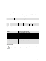
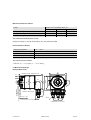
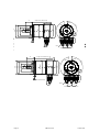
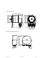
ABSOLUTE ROTARY ENCO DER W ITH CAN-BUS INTERFACE
USER MANUAL
Imprint
FRABA POSITAL GmbH
Disclaimer of Warranty
FRABA
POSITAL
GmbH
Schanzenstraße 35
D-51063 Köln
representations or warranties, either express or
implied, by or with respect to anything in this
Telefon +49 (0) 221 96213-0
Telefax +49 (0) 221 96213-20
manual, and shall not be liable for any implied
warranties of merchantability and fitness for a
Internet
e-mail
particular purpose or for any indirect, special, or
consequential damages.
http://www.posital.com
[email protected]
makes
no
Copyright
Version date:
24. September 2004
The company FRABA POSITAL GmbH claims
copyright on this documentation. It is not allowed to
Version number:
Article number:
2.3
99998101
modify, to extend, to hand over to a third party and
to copy this documentation without written approval
Author:
Marcus Staszewski / Klaus
Matzker
by the company FRABA POSITAL GmbH. Nor is
any liability assumed for damages resulting from
the use of the information contained herein.
Further, this publication and features described
herein are subject to change without notice.
Alteration of Specifications reserved
Technical specifications, which are described in
this manual, are subject to change due to our
permanent strive to improve our products.
Page 2
UME-OCD-CAN
Version 09/04
1. Introduction...................................................... 4
1.1 Absolute rotary encoder................................... 4
4.5.3 Limit switch, max: ........................................27
4.5.4 Programming example: Limit switch, Max.: .28
1.2 CANopen technology ....................................... 4
1.3 CAN Communication Reference Model ........... 6
4.6 Changing the node number............................28
4.6.1 Example: Changing the node number .........29
1.4 Definitions ........................................................ 7
4.7 Adjusting the baudrate ...................................30
4.7.1 Example : Adjusting the baudrate ...............31
2. Installation ........................................................ 8
2.1 Electrical Connection ....................................... 8
4.8 Transmission Mode ........................................31
4.8.1 Cyclic Mode.................................................31
2.1.1 Bus connection ............................................. 9
2.1.2 Cable connection .......................................... 9
4.8.2 Disable the cyclic mode ..............................32
4.8.3 Sync Mode ..................................................32
2.1.3 Bus Termination............................................ 9
2.2 Bus address................................................... 10
4.8.4 Example: Number of Sync telegrams ..........33
4.8.5 Polled Mode ................................................33
2.2.1 Setting of the node number......................... 10
2.3 Setting of the baudrate................................... 10
4.9 Memory Transfer............................................34
4.10 Wiederherstellen der Standardeinstellungen35
2.4 Meaning of the LEDs in the connection cap... 11
2.5 Troubleshooting ............................................. 12
5. Technical Data................................................35
3. Device Configuration..................................... 13
5.1. Electrical Data ...............................................35
5.2. Mechanical Data ...........................................35
3.1. CANopen data transmission ......................... 13
3.1.1 The COB-ID ................................................ 13
5.3 Mechanical Drawings .....................................37
5.4 Cable and connectors ....................................46
3.1.2 The Command Byte .................................... 14
3.1.3 The Object Directory ................................... 15
6. Models/Ordering Description ........................49
3.3.1 Manufacturer Specific Objects .................... 16
3.2 Operational Status ......................................... 17
6.1 Combinationmatrix .........................................50
6.2 Connection caps ............................................50
3.2.1 Status: Operational ..................................... 17
3.2.2 Status: Pre-Operational .............................. 17
6.3 Accessories and documentation ....................51
3.2.3 Reset of the absolute rotary encoder .......... 18
3.3 Transmission of the Actual Position ............... 18
7. Appendix.........................................................52
7.1 History encoder generations ..........................52
4. Programming ................................................. 19
7.1.1 Encodergeneration Optocode .....................52
7.1.2 Encodergeneration AWC.............................52
4.1 Operating Parameters.................................... 19
4.1.1 Programming example: Operational
7.2 List of tables ...................................................55
7.3 List of figures..................................................55
parameter ............................................................ 20
4.2 Resolution per Revolution.............................. 21
7.4 Document history ...........................................55
4.2.1 Programming example: Resolution per
revolution ............................................................. 22
4.3 Total resolution .............................................. 22
4.3.1 Programming example: Total resolution ..... 24
4.4 Preset Value .................................................. 25
4.4.1 Programming example: Preset value .......... 25
4.5 Limit Switch, Min. and Max. ........................... 26
4.5.1 Limit switch, Min:......................................... 26
4.5.2 Programming example: Limit switch, min. ... 27
Version 09/04
UME-OCD-CAN
Page 3
1. Introduction
This manual describes the implementing and
-
Node number
configuration of an absolute rotary encoder with
CANopen interface. The device fullfills the
-
velocity
requirements of a CANopen device regarding
the device specification DS406 of the CANopen
The general use of absolute rotary encoders
with CAN-Bus interface using the CAN Open
user group.
protocol is guaranteed.
1.1 Absolute rotary encoder
The basic principle of an absolute rotary encoder
1.2 CANopen technology
CAN stands for Controller Area Network and
is the optical sampling of a transparent code disc
which is fixed with the driving shaft.
was developed by the company Bosch for
applications within the automobile area. In the
The absolute rotary encoder has a maximum
resolution of 65536 steps per revolution (16 Bit).
meantime CAN has become increasingly used
for industrial applications. CAN is a multi -
The Multi-Turn version can detect up to 16384
revolutions (14 Bit). Therefore the largest
masterable system, i.e. all users can access the
bus at any time as long as it is free. CAN
30
resulting resolution is 30 Bit = 2
=
1.073.741.824 steps. The standard Single -Turn
doesn?t operate with addresses but with
message identifiers. Access to the bus is
version has 12 Bit, the standard Multi -Turn
version 24 Bit.
performed according to the CSMA/CA principle
(carrier sense multiple access with collision
For further information about the function
avoidance), i.e. each user listens if the bus is
free, and if so, is allowed to send messages. If
principle or the setup of a CANopen net work
please
refer
two users attempt to access the bus
simultaneously, the one with the highest priori ty
http://www.posital.com/products/encoder_abc/en
coder_abc.html
(lowest identifier) receives the permission to
send. Users with lower priority interrupt their
Open functions. The following modes can be
data transfer and will access the bus when it is
free again. Messages can be received by every
programmed and enabled or disabled:
- Polled Mode
participant. Controlled by an acceptance filter
the participant accepts only messages that are
- Cyclic Mode
- Sync Mode
intended for it.
CANopen
Transmission Technology: Two-core cable
The protocol supports the programming of the
following additional functions:
Baud rates:
Participants:
20 kBaud up to 1 MBaud
maximum 127
Cable Length:
30 m for 1 MBaud
5000 m for 20 kBaud
-
Code sequence (Complement)
Resolution per revolution
-
Total revolutions
Preset value
The data communication is done via message
-
Two limit switches
Baudrate
telegrams. In general, telegrams can be split in a
COB-Identifier and up to 8 following bytes. The
Page 4
UME-OCD-CAN
Version 09/04
COB-Identifier, which determines the priority of
the message, is made from the function code
required to answer after each sync
message, a parameter sync counter
and the node number.
can be programmed to skip a certain
number of sync messages before
The node number is uniquely assigned to each
user. With a FRABA rotary encoder this number
answering again
is assigned with by numerical coded turn
switches in the connection cap. The function
-
code varies according to the type of message
transmitted:
Change of state mode:
The position value is transferred when
changing
-
Administrative messages (LMT, NMT)
Further functions (direction of rotation,
resolution,etc..) can be parameterized. FRABA
-
Service data objects (SDOs)
Process data Objects (PDOs)
rotary encoders correspond with the class 2
profile for encoder (DSP 406), whereby the
pre-defined messages
emergency messages)
characteristics of rotary encoders with CANopen
interface are defined. The link to the bus is made
-
(synchronization,
PDOs (Process Data Objects) are needed for
by terminal blocks in the connection cap. In
additon, the node number and Baud rate are set
real time data exchange. Since this messages
possess a high priority, the function code and
with turn switches. For configuration and
parameterization various software tools are
therefore the identifier are low. SDOs (service
data objects) are necessary for the bus node
available from different providers. With the help
of the provided EDS file (electronic datasheet)
configuration
(e.g.
transfer
of
device
parameters). Because these message telegrams
simple line-up and programming are possible.
are tranferred acyclicly (usually only while
powering up the network), the priority is low.
FRABA rotary encoders with CANopen interface
support all CANopen functions. The following
operating modes can be programmed:
-
Polled mode:
The position value is only given upon
request
-
Cyclic Mode:
The position value is written cyclically
(interval adjustable) to the bus
-
Sync mode:
After receiving a sync message by the
host, the encoder answers with the
current process value. If a node is not
Version 09/04
UME-OCD-CAN
Page 5
1.3 CAN Communication Reference Model
The communication concept can be described similar to the ISO -OSI Reference Model:
Device A
Device B
Device C
Device X
ISO/OSI Layer 7: CAL
NMT
DBT
LMT
CMS
ISO/OSI Layer 2: Data Link Layer
ISO/OSI Layer 1: Physical Layer
CAN Bus
The
communication
model*
supports
synchronous and asynchronous messages. With
respect to the functionality four different
message objects are provided:
Administrational Messages (LMT, NMT)
Service Data Messages (SDO)
Process Data Messages (PDO)
Pre-defined Messages (Synchronisation and
Emergency Messages)
Further information is available at:
CAN in Automation (CiA) International Users
and Manufacturers Group e.V.
Am Weichselgarten 26
D-91058 Erlangen
(*) Reference:
CAN Application Layer for
Industrial Applications
CiA Draft Standard 201 ... 207, Version 1.1
CAL-based Communication Profile for
Industrial Systems
CiA Draft Standard 301
Page 6
UME-OCD-CAN
Version 09/04
1.4 Definitions
CAN
Controller Area Network
Additionally, following abbreviations are used in the
CAL
CMS
CAN Application Layer
CAN Message Specification.
manual:
One of the service elements of the
application layer in the CAN Reference
APV
CW
Absolute Position Value
Clockwise. Turning direction as seen on
Model.
Communication Object. (CAN message)
CCW
shaft.
Counterclockwise. Turning direction as
A unit of transportation in a CAN Network.
Data must be sent across a Network
FC
seen on shaft.
Function code. It determines the kind of
COB
inside a COB.
COB-ID COB-Identfier. Identifies a COB uniquely
LMT
message, which is sent across the CAN
network.
in a Network. The identifier determines
the
NN
priority of that COB.
Layer Management. One of the service
PV
PCV
Node number. It determines uniquely the
CAN device.
Preset value
Process value
elements of the application layer in the
CAN
Reference Model. It serves to configure
parameters of each layer in the CAN
NMT
Reference Model.
Network Management. One of the service
elements of the application layer in the
CAN
Reference Model. It performs initialisation,
configuration and error handling in a CAN
SDO
network.
Service Data Object. A data object with
PDO
low priority to configure a CAN node.
Process Data Object. A data object with
high priority to
synchronous and
transmit
data
in
asynchronous modes.
Version 09/04
UME-OCD-CAN
Page 7
2. Installation
2.1 Electrical Connection
The rotary encoder is connected by three cables.
The power supply is achieved with a two-wire
Clamp
Description
connection cable through one PG 9. Each one of
the twisted-pair and shielded bus lines are guided
⊥
Ground
+
24 V Supply voltage
-
0 V Supply voltage
CG
CAN Ground
CL
CAN Low
CH
CAN High
CG
CAN Ground
CL
CAN Low
CH
CAN High
in and out through two PG 9 on the right side (as
seen on clamps)
Instructions
to
mechanically
install
and
electrically connect the angular encoder
Do
not
remove
or
mount
the
connection cap while the encoder is
under power!
RT
ON
Do not stand on the encoder!
-
G L
78
78
L
901
23
23
23
456
456
456
Do not adapt the driving shaft
additionally!
H G
901
901
78
+
Bd
x10
x1
Avoid mechanical load!
Do
not
adapt
the
housing
Fig. 1 Connection cap inside
additionally!
BCD coded rotary switches
Dvice address 0...89
x1 Setting CAN-node number
x10 Adress reserved 90…99
xBd
Setting of the baud-rate
H
RT
2.1.1 Bus connection
The connection cap fulfills the function of a T -
ON
coupler. From there the wiring must be done
according to the drawing on the left side. Please
note the assignment of incoming and outgoing bus
signals.
+
-
G L
H G
L
H
An
Bus In
activated
bus
termination
resistor will lead into a separation
of bus in and bus out signals!
Bus Out
2.1.2 Cable connection
Remove screw, sealing and cone from the cable
gland. Remove 55 mm of the sheat and 50 mm of
the shielding. About 5 mm of the wires should be
de-isolated. Put screw, and sealing on the cable.
The cone should be mounted under the shielding
according to the figure 3. Put the whole cable into
the cable gland and tighten the screw.
Fig. 3 Connection cap bus in and bus out
2.1.3 Bus Termination
If the encoder is connected at the end or beginning
55 mm
50 mm
5 mm
5 mm
of the bus the termination resistor must be
switched on. The termination resistor is switched
on when the switch is in the ON posit ion.
Separation of Bus In and Bus Out
signals if termination resistor is
Fig. 4 Cable preparation
activated.
There is a resistor provided in the connection cap,
which must be used as a line termination on the
last device.
Resistor:
RT
Fig. 2 Cable connection
ON
Last Device
Version 09/04
UME-OCD-CAN
RT
ON
Device X
Page 9
2.2 Bus address
Baudrate in kBit/s BCD coded rotary switches
The setting of the node number is achieved turnswitches in the connection cap. Possible (valid)
20
0
addresses lie between 0 and 89 whereby every
address can only be used once. 2 LEDs on the
50
1
100
2
125
3
250
4
500
5
The CANopen Encoder adds internal
800
6
1 to the adjusted device address.
1000
7
reserved
8..9
backside of the connection cap show the operating
status of the encoder.
2.2.1 Setting of the node number
The setting of the node number is achieved by two
turn-switches in the connection cap. The customer
can easily remove the connection cap for
installation by removing two screws at the backside
of the encoder. The meaning and the positioning of
the two turn-switches you can see in figure 1.
Tab. 2 Assignment baudrate and turn switch
If the device has a connector or a cable exit
instead of a connection cap the node number can
only be adjusted via SDO objects. The default
baudrate is 20 kBaud. Please regard point 4.7 for
further information about setting of the baudrate
via SDO objects.
If the device has a connector or a cable exit
instead of a connection cap the node number can
only be adjusted via SDO objects. The default
node number is in this case 32. Please regard
point 4.6 for further information of setting the node
number via SDO objects.
2.3 Setting of the baudrate
The adjusting of the baudrate is achieved by one
turn switch in the connection cap.The following
baudrates are possible:
Protocol Definition via BCD address switches
x1
Device address 97
x10 Automatic protocol selection according to
kind of connection cap
x1
Device address 98
x10 Protocol selection according to DS301 -V3
x1 Device address 99
x10 Protocol selection according to DS301 -V4
Tab. 1 Protocol definition via BCD turn switches
Page 10
UME-OCD-CAN
Version 09/04
2.4 Meaning of the LEDs in the connection cap
LED grün
green
LED grün
/green
Err
Sta
Fig. 5 Backside connection cap
Err
Green LED
Sta
Green LED
Meaning
off
off
No power supply
off
on
Encoder is ready, Boot Up message not sent (no further device
on network, wrong baud rate) or encoder in prepared status
flashing
on
Boot Up message sent, device configuration is possible
on
on
Normal operation mode, Encoder in Operational Status
Tab. 3 Meaning status LED’s
Version 09/04
UME-OCD-CAN
Page 11
2.5 Troubleshooting
2.5.4 Limit switches without function
2.5.1 Power on – Encoder doesn’t respond
Problem:
The encoder didn’t transmit the bits for the limit
Problem:
The bus is active but the installed encoder
switches.
transmitted no boot up message.
Possible solution:
The limit switch functionality has to be activated
Possible solution:
switch of the PLC
once. Please follow the descripting you can find at
4.5.
-
remove the connection cap of the encoder
check the 2 turn-switches for th baudrate
Assemble the connection cap
power on
2.5.5 Encoder without connection cap, Version
C5 und C6
2.5.2 Malfunction of the position value during
Notice: The changing of baudrate and node
number are only valid after a new power up, NMT
transmission
Reset
Problem:
During the transmission of
or
the
store
parameters
command.
the position value
occasional malfunctions occurs. The CAN bus can
be temporabily in the bus off stat e also.
Possible solution:
Check, if the last bus node has switched on the
terminal resistor. If the last bus node is an encoder
the terminal resistor is suited in the connection
cap..
2.5.3 Too much ERROR-Frames
Problem:
The bus load is too high in case of too much error
frames.
Possible solution:
Check if all bus node has the same baudrate. If
one node has another baudrate error frames are
produced automatically. The setting of the
baudrate is descripted in this manual under 2.2
and 4.6.
Page 12
UME-OCD-CAN
Version 09/04
3. Device Configuration
3.1. CANopen data transmission
The data transmission in the CAN network is
realised by message telegrams. Basically, these
COB-ID
Command
Index
11 Bit
Byte 0
Byte 1
Byte 2
Low
High
telegrams can be divided into the COB-ID and 8
following bytes as shown in the table below:
Subindex
Service-/Process- Data
Byte 3
Byte 4
Byte 5
Byte 6
Byte 7
Low
→
→
High
3.1.1 The COB-ID
The 11 Bit of COB-Identifier is built as follows:
10
9
8
7
Function code
X
The
X
X
6
5
4
3
2
1
0
X
X
X
X
Node number
X
COB-Identifier
X
X
determines
X
uniquely
X: free selectable
the
The node number can be adjusted by 2 rotary
message object. It is built by the function code,
identifying the message class and the node
switches in the connection cap or optionally on
customer request by a SDO.
number, which determines the absolute encoder.
Following function codes are available:
Object
Function Code (Binary)
(rx) and (tx) as seen by the master !
Result. COB-ID
Priority Class*
NMT
0000
0
0
SYNC
0001
128
0
Emergency
0001
129 - 255
0,1
PDO (rx)
0011
385 - 511
1,2
PDO (tx)
0100
513 - 639
2
PDO (rx)
0101
641 - 767
2,3
PDO (tx)
0110
769 - 895
3,4
SDO (rx)
1011
1409 - 1535
6
SDO (tx)
1100
1537 - 1663
6,7
Tab. 4 Overview priority of the CANopen objects
*Priority: 0 = highest priority, 7 = lowest priority
Version 09/04
UME-OCD-CAN
Page 13
3.1.2 The Command Byte
The command byte contents the kind of telegram
The Request-Telegram is used by the master to
which is sent across the CAN network. One divides
three kinds of telegrams: a Set-Parameter-
read back stored parameters from a node.
Telegram (Domain Download), a RequestTelegram (Domain Upload) and Warnings.
Warnings are sent by the absolute rotary encoder
to the master, if a sent telegram cannot be
processed accordingly.
The Set-Parameter-Telegram is used to send
parameter data
configuration.
to
the
encoder
(node)
for
Command
Function
Telegram
Description
22h
Domain Download
Request
Parameter to encoder
60h
Domain Download
Confirmation
Parameter received
40h
Domain Upload
Request
Parameter request
43h, 4Bh, 4Fh (*)
Domain Upload
Reply
Parameter to Master
80 h
Warning
Reply
Transmission error
Tab. 5 Command description
(*)The value of the command byte depends on the data length of the called parameter:
Command
Data length
Data length
43h
4 Byte
Unsigned 32
4Bh
2 Byte
Unsigned 16
4Fh
1 Byte
Unsigned 8
Tab. 6 Data length against command byte
Page 14
UME-OCD-CAN
Version 09/04
3.1.3 The Object Directory
The data transmission according to CAL is realised
exclusively by object oriented data messages. The
objects are classified in groups by an index record.
Each index entry can be subdivided by sub indices. The overall layout of the standard object
dictionary is shown beside:
Index (hex)
Object
0000
not used
0001-001F
Static Data Types
0020-003F
Complex Data Types
0040-005F
Manufacturer Specific Data Types
0060-0FFF
Reserved for further use
1000-1FFF
Communication Profile Area
2000-5FFF
Manufacturer Specific Profile Area
6000-9FFF
Standardised Device Profile Area
A000-FFFF
Reserved for further use
Tab. 7 General object dictionary
Following objects according to the communication profile CAN OPEN (refer to DS 301) are implemented
into the absolute rotary encoder:
Index
Object
Name
Data Length
Attr.
1000h
VAR
Device type
Unsigned32
const
1001h
VAR
error register
Unsigned8
ro
1002h
VAR
manufacturer status register
Unsigned32
ro
1003h
ARRAY
pre-defined error field
Unsigned32
ro
1004h
Reserved for compatibility reason
1005h
VAR
COB-ID SYNC-message
Unsigned32
rw
1008h
VAR
device name
Vis-String
const
1009h
VAR
hardware version
Vis-String
const
100Ah
VAR
software version
Vis-String
const
100Bh
Reserved for compatibility reason
1010h
VAR
Store parameters
Unsigned32
rw
1011h
VAR
Restor parameters
Unsigned32
rw
Tab. 8 Object dictionary according DS301
Version 09/04
UME-OCD-CAN
Page 15
3.3.1 Manufacturer Specific Objects
Additionally, following manufacturer specific communication objects are implemented:
Index
Subindex Object
1800h
Name
Data length
RECORD
Communication parameter PDO 1
Attr.
ro
1800h
0h
VAR
number of supp. entries
Unsigned 8
ro
1800h
1h
VAR
COB-ID used by PDO
Unsigned 32
rw
1800h
2h
VAR
transmission type
Unsigned 8
rw
1800h
3h
VAR
inhibit time
Unsigned 8
rw
1802h
RECORD
Communication parameter PDO 2
1802h
0h
VAR
number of supp. entries
Unsigned 8
ro
ro
1802h
1h
VAR
COB-ID used by PDO
Unsigned 32
rw
1802h
2h
VAR
transmission type
Unsigned 8
rw
1802h
3h
VAR
inhibit time
Unsigned 8
rw
2000h
VAR
process value
Unsigned 32
ro
2100h
VAR
operating parameters
Unsigned 16
rw
2101h
VAR
resolution/revolution
Unsigned 16
rw
2102h
VAR
total resolution
Unsigned 32
rw
2103h
VAR
preset value
Unsigned 32
rw
2104h
VAR
Limit switch, min.
Unsigned 32
rw
2105h
VAR
Limit switch, max.
Unsigned 32
rw
2200h
VAR
Cycle time
Unsigned16
rw
2300h
VAR
Store parameters
Unsigned32
wo
Tab. 9 Manufacturer specific object dictionary
Index
Subindex
Objekt
Name
Datenlänge
Attr.
3000h
VAR
Knotennummer
Unsigned 8
rw
3001h
VAR
Datenrate
Unsigned 8
rw
Tab. 10 Nodenumber and baudrate
The programmable communication objects and encoder parameters are explained in detail in the next
chapter.
VAR:
Variable
RECORD: Data field
ARRAY:
Data field
ro:
read only
rw:
read, write
wo:
write only
Page 16
UME-OCD-CAN
Version 09/04
3.2 Operational Status
The absolute rotary encoder accesses the CAN network 4 s after power on in pre -operational status:
FC
NN
1110
XXXXXXX
Comand
Index
Subindex
S-/P-Data
Description
Boot-Up message
All values except the FC are hexadecimal
It is recommended, to set the parameters (see: 7.2
Programming) while the Encoder is in the pre -
correctness of the sent/received SDOs. As it is not
possible to send or receive PDOs in pre -
operational status. During this status activity on the
network is low what makes it easier to prove the
operational status, stress for the Encoder will be
reduced.
3.2.1 Status: Operational
To put one or all nodes in the operational state,
following message is sent by the master:
FC
NN
0000 b 0 d
Command
Index
01 h
00
Subindex
S-/P-Data
Description
NMT-Start, all nodes
0000 b 0 d
01 h
NN
It is possible to put all the nodes in operational
NMT-Start, NN
status (Index 0) or only one node (Index NN).
3.2.2 Status: Pre-Operational
To set one node in the Pre-Operational state the following telegram has to be transmitted from the master:
FC
NN
Command
Index
0000 b
0d
80 h
NN
Subindex
S-/P-Data
Description
NMT-PreOp, NN
NN: node number
Version 09/04
UME-OCD-CAN
Page 17
3.2.3 Reset of the absolute rotary encoder
If a node is not functioning well, it is recommended to perform a RESET:
FC
NN
Command
Index
Subindex
S-/P-Data
0000 b 0 d
NN: node number
81 h
NN
Description
NMT-Reset, NN
The notified Absolute Rotary Encoder accesses the bus in pre -operational status after resetting .
3.3 Transmission of the Actual Position
The process value is sent across the CAN network with the following telegram:
COB-ID
Process value
11 Bit
Byte 0
7
2 to 2
Byte 1
0
2
15
to 2
Byte 2
8
2
23
to 2
Byte 3
16
2
31
to 2
24
The COB-ID contains the node number and the according PDO(rx). By default the process value is sent
with the function code PDO(rx) 0011 and as a response to the Sync -telegram with the function code
PDO(rx) 0101.
Page 18
UME-OCD-CAN
Version 09/04
4. Programming
The setting of parameters should be done
always in pre-operational status. The monitoring
Following values are written in hexadecimal
notation with the exception of the function
of the sent and received messages becomes
much easier.
code which value is given binary and the
node number (decimal value).
It is important to follow the presented sequence
of the parameter settings. If values of
Every parameter has a general description and
an example.
parameters are not changed then
they can be skipped.
4.1 Operating Parameters
As operating parameters the code sequence
(Complement) can be selected and the limit
switches can be turned on or off.
CMS
Index
Default value
Value range
Data length
SDO
2100h
0h
0h - Fh
Unsigned16
General parameter description
Master to Absolute Rotary Encoder:
FC
NN
SDO(tx)
1100 b
1-90 d
Set-Parameter
Command
Index
Download
2100h
22
00
Subindex
Service/Process data
Byte 4
21
The parameter code sequence (Complement)
determines the counting direct ion, in which the
output process value increases or decreases. The
code sequence is determined by Bit 0 in Index
2100h:
00
Byte 5
Byte 6
Byte 7
X
00
00
00
X: Hex value of bit combination bit 0 -2
Bit 0
Code sequence Code
0
CW
increasing
1
CCW
increasing
Additionally, the two limit switches, Min. and Max.
can be turned on or off in Index 2100h:
Bit 1
Limit switch, min.
Bit 2 Limit switch, max.
0
turned off
0
turned off
1
turned on
1
turned on
Version 09/04
UME-OCD-CAN
Page 19
After a successful tramnsmission the encoder answered with the following confirmation telegram:
FC
NN
SDO(rx)
1011 b
1-90 d
Command
Index
Subindex
Download
2100h
60
00
21
00
Service/Process data
Byte 4
Byte 5
Byte 6
Byte 7
00
00
00
00
4.1.1 Programming example: Operational parameter
Target: Absolute rotary encoder with direction CCW increasing and both limit switches disabled
Bitmatrix:
Bit 0 = 1
Bit 1 = 0
Direction increasing (CCW)
Limit switch min. disabled
Bit 2 = 0
Limit switch max. disabled
Result bitmatrix X = 01h
Nodenumber NN = 01
Master to Absolute Rotary Encoder:
FC
NN
SDO(tx)
1100 b
01 d
Command
Index
Download
2100h
22
00
Absolute Rotary Encoder to Master:
FC
NN
SDO(rx)
1011 b
Page 20
01 d
Set-Parameter
Subindex
21
Service/Process data
Byte 4
Byte 5
Byte 6
Byte 7
00
01
00
00
00
Subindex
Service/Process data
Confirmation
Command
Index
Download
2100h
60
00
21
00
UME-OCD-CAN
Byte 4
Byte 5
Byte 6
Byte 7
00
00
00
00
Version 09/04
4.2 Resolution per Revolution
The parameter Resolution per Revolution is used
revolution. Each value between 1 and 65536 can
to program the desired number of steps per
be realised.
CMS
Index
Default value
Value range
Data length
SDO
2101h
(*)
0h - 8000h
Unsigned16
(*) see: type sign
The following value range is valid for a resolution per revolution of 16 bit
Version 09/04
UME-OCD-CAN
Page 21
CMS
Index
Default value
Value range
Data length
SDO
2101h
(*)
0h - 10000h
Unsigned32
(*) see: type sign
General parameter description
Master to Absolute Rotary Encoder:
FC
NN
SDO(tx)
Set-Parameter
Command
Index
Subindex
Download
2101h
1100 b 1-90 d
22
01
X: desired resolution per revolution (>15 Bit)
21
00
Service/Process data
Byte 4
Byte 5
Byte 6
Byte 7
X
X
Y
Y
Y: desired resolution per revolution (16 Bit)
If the desired value exceeds the hardware resolution of the encoder, the code will not be transmitted
stepwise. So it is important, to keep the parameter in the possible value range.
After a successful tramnsmission the encoder answered with the following confirmation telegram:
FC
NN
SDO(rx)
1011 b
1-90 d
Command
Index
Download
2101h
60
01
Subindex
21
00
Service/Process data
Byte 4
Byte 5
Byte 6
Byte 7
00
00
00
00
4.2.1 Programming example: Resolution per revolution
Target: Absolute rotary encoder with 4096 steps per revolution
Resolution per revolution: 4096 steps = 1000 h
Node Number NN = 1
Master to Absolute Rotary Encoder:
FC
NN
SDO(tx)
1100 b
1-90 d
Command
Index
Download
2101h
22
01
Absolute Rotary Encoder to Master:
FC
NN
SDO(rx)
1011 b
1-90 d
Set-Parameter
Subindex
21
Service/Process data
Byte 4
Byte 5
Byte 6
Byte 7
00
X
X
Y
Y
Subindex
Service/Process data
Confirmation
Command
Index
Download
2101h
60
01
21
00
Byte 4
Byte 5
Byte 6
Byte 7
00
00
00
00
4.3 Total resolution
Page 22
UME-OCD-CAN
Version 09/04
This parameter is used to program the desired number of measuring units over the total measuring range.
This value must not exceed the total resolution of the absolute rotary encoder, w hich is printed on the type
plate of the encoder.
CMS
Index
Default value
Value range
Data length
SDO
2102h
(*)
0h - 4.000.000h
Unsigned32
(*) refer to: type plate of encoder
Attention:
Following formula letter will be used:
PGA
PAU
Physical total resolution of the encoder
Physical resolution per revolution
GA
Total resolution
(customer parameter)
AU
Resolution per revolution
(customer parameter)
(see type shield)
(see type shield)
If the desired resolution per revolution is less than
the really physical resolution per revolution of the
encoder, then the total resolution must be entered
as follows:
Total resolution:
GA =
( PGA ∗ AU ) , AU ≤ PAU
PAU
Calculation example:
Customer handicap: AU = 2048,
Encoder type shield:
PGA=24 bit, PAU=12bit
Version 09/04
Fig. 6 Calculation formula for
total resolution
GA =
(16777216 ∗ 2048 )
4096
GA = 8388608
UME-OCD-CAN
Page 23
If the total resolution of the encoder is less than the
physical total resolution, the parameter total
k=
resolution must be a multiple of the physical total
resolution:
General parameter description
Master to Absolute Rotary Encoder:
FC
NN
SDO(tx)
1100 b
1-90 d
PGA
, k = ganze Zahl
GA
Set-Parameter
Command
Index
Download
2102h
Subindex
22
02
21
00
Service/Process data
Byte 4
Byte 5
Byte 6
Byte 7
X
X
X
X
X: desired total resolution
After a successful transmission the encoder answered with the following confirmation telegram:
FC
NN
SDO(rx)
1011 b
1-90 d
Command
Index
Download
2102h
Subindex
60
02
21
00
Service/Process data
Byte 4
Byte 5
Byte 6
Byte 7
00
00
00
00
4.3.1 Programming example: Total resolution
Target: Absolute rotary encoder with a total resolution of 24 bit
Total resolution 24 bit is equivalent to 1000000 h
Node number NN = 1
Master to Absolute Rotary Encoder:
FC
NN
SDO(tx)
1100 b
01 d
Set-Parameter
Command
Index
Download
2102h
Subindex
22
02
21
00
Service/Process data
Byte 4
Byte 5
Byte 6
Byte 7
00
00
00
01
X: desired total resolution
After a successful transmission the encoder answered with the following confirmation telegram:
FC
NN
SDO(rx)
1011 b
Page 24
01 d
Command
Index
Download
2102h
Subindex
60
02
21
00
UME-OCD-CAN
Service/Process data
Byte 4
Byte 5
Byte 6
Byte 7
00
00
00
00
Version 09/04
4.4 Preset Value
The preset value is the desired position value,
The preset value must not exceed the parameter
which should be reached at a certain physical
position of the axis. The position value is set to the
total resolution to avoid run-time errors.
desired process value by the parameter preset.
CMS Index
Default value
Value range
Data length
SDO 2103h
0h
0h - total resolution
Unsigned32
General parameter description
Master to Absolute Rotary Encoder:
FC
NN
SDO(tx)
1100 b
1-90 d
Set-Parameter
Command
Index
Subindex
Download
2103h
22
03
21
00
Service/Process data
Byte 4
Byte 5
Byte 6
Byte 7
X
X
X
X
X: desired preset value
After a successful transmission the encoder answered with the following confirmation telegram:
FC
NN
SDO(rx)
1011 b
1-90 d
Command
Index
Subindex
Download
2103h
60
03
21
00
Service/Process data
Byte 4
Byte 5
Byte 6
Byte 7
00
00
00
00
4.4.1 Programming example: Preset value
Target: Absolute rotary encoder with the preset value 0
Preset value 0 is equivalent to X = 0h
Node number NN = 1
Master to Absolute Rotary Encoder:
FC
NN
SDO(tx)
1100 b
01 d
Set-Parameter
Command
Index
Download
2103h
Subindex
22
03
21
00
Service/Process data
Byte 4
Byte 5
Byte 6
Byte 7
00
00
00
00
X: desired preset value
Absolute Rotary Encoder to Master:
FC
NN
SDO(rx)
1011 b
Version 09/04
01 d
Confirmation
Command
Index
Download
2103h
Subindex
60
03
21
00
UME-OCD-CAN
Service/Process data
Byte 4
Byte 5
Byte 6
Byte 7
00
00
00
00
Page 25
4.5 Limit Switch, Min. and Max.
Two position values can be programmed as limi t
Bit 30 = 1:
Limit Switch, Min. reached or passed
switches. By reaching these values one bit of the
32 bit process value is set to high. Both
Bit 31 = 1:
under
Limit Switch, Max. reached or passed
programmed values must not exceed the
parameter total resolution to avoid run -time errors.
beyond
4.5.1 Limit switch, Min:
CMS
Index
Default value
Value range
Data length
SDO
2104h
0h
0h - total resolution
Unsigned32
The limit switch, Min sets Bit 30=1 with the next
message telegram, if the process value r eaches
or passes under the value of the limit switch:
Function
Statusbits
Process value
Bit
31 30 29 28 27 26 25 24 23 22 21 20 19 18 17 16 15 14 13 12 11 10 9 8 7 6 5 4 3 2 1 0
0 1 0 0 0 0 0 X X X X X X X X X X X X X X X X X X X X X X X X X
General parameter description
Master to Absolute Rotary Encoder:
FC
NN
SDO(tx)
1100 b
1-90 d
Set-Parameter
Command
Index
Download
2104h
Subindex
22
04
21
00
Service/Process data
Byte 4
Byte 5
Byte 6
Byte 7
X
X
X
X
X: desired minimum value
After a successful transmission the encoder answered with the following confirmation telegram:
FC
NN
SDO(rx)
1011 b
Page 26
1-90 d
Command
Index
Download
2104h
Subindex
60
04
Service/Process data
Byte 4
21
00
UME-OCD-CAN
00
Byte 7
00
00
00
Version 09/04
4.5.2 Programming example: Limit switch, min.
Target: Absolute rotary encoder with limit switch min.
Limit switch ma. position: X = 1000h (is equivalent to 4096 d)
Node number: NN = 1
Master to Absolute Rotary Encoder: Set-Parameter
FC
NN
SDO(tx)
1100 b
01 d
Command
Index
Download
2104h
22
04
Subindex
21
Service/Process data
Byte 4
Byte 5
Byte 6
Byte 7
00
00
10
00
00
Subindex
Service/Process data
X: desired maximum value
Absolute Rotary Encoder to Master:
FC
NN
SDO(rx)
1011 b
01 d
Confirmation
Command
Index
Download
2104h
60
04
21
00
Byte 4
Byte 5
Byte 6
Byte 7
00
00
00
00
4.5.3 Limit switch, max:
CMS
Index
Default value
Value range
Data length
SDO
2105h
0h
0h - total resolution
Unsigned32
The limit switch, max sets Bit 31=1 with the next
message telegram, if the process value r eaches
or passes over the value of the limit switch:
Function
Statusbits
Process value
Bit
31 30 29 28 27 26 25 24 23 22 21 20 19 18 17 16 15 14 13 12 11 10 9 8 7 6 5 4 3 2 1 0
1 0 0 0 0 0 0 X X X X X X X X X X X X X X X X X X X X X X X X X
General parameter description
Master to Absolute Rotary Encoder: Set-Parameter
FC
NN
SDO(tx)
1100 b
1-90 d
Command
Index
Download
2105h
22
05
Subindex
21
00
Service/Process data
Byte 4
Byte 5
Byte 6
Byte 7
X
X
X
X
X: desired maximum value
After a successful transmission the encoder answered with the following confirmation telegram:
FC
Version 09/04
NN
Command
Index
Subindex
UME-OCD-CAN
Service/Process data
Page 27
SDO(rx)
1011 b
1-90 d
Download
2105h
60
05
21
Byte 4
Byte 5
Byte 6
Byte 7
00
00
00
00
00
Subindex
Service/Process data
4.5.4 Programming example: Limit switch, Max.:
Target: Absolute rotary encoder with limit switch max.
Limit switch ma. position: X = 5000h
Node number: NN = 1
Master to Absolute Rotary Encoder: Set-Parameter
FC
NN
SDO(tx)
1100 b
01 d
Command
Index
Download
2105h
22
05
21
Byte 4
Byte 5
Byte 6
Byte 7
00
00
50
00
00
Subindex
Service/Process data
X: desired maximum value
Absolute Rotary Encoder to Master:
FC
NN
SDO(rx)
1011 b
01 d
Confirmation
Command
Index
Download
2105h
60
05
21
00
Byte 4
Byte 5
Byte 6
Byte 7
00
00
00
00
4.6 Changing the node number
CMS Index
Defaultvalue
Value range
Data length
SDO 3000h
20h
0h-89h
Unsigned 8
General parameter description
FC
KN
SDO(tx)
1100 b
1-90 d
Command
Index
Download
3000h
22
00
Subindex
30
00
Service-/Processdata
Byte 4
Byte 5
Byte 6
Byte 7
X
00
00
00
X: 7 Bit to adjust the node number
After successful transmission the encoder answered with the following telegram:
FC
NN
SDO(rx)
1011 b
Page 28
1-90 d
Command
Index
Download
3000h
60
00
Subindex
30
00
UME-OCD-CAN
Service-/Processdata
Byte 4
Byte 5
Byte 6
Byte 7
00
00
00
00
Version 09/04
4.6.1 Example: Changing the node number
Target: Absolute rotary encoder with node number 5
Default node number: 32 d
The changed node number is confirmed by the encoder but only after a
-
Store command (Objekt 2300 hex)
-
Store command (Objekt 1010 hex) and NMT reset module or NMT reset communikation
valid.
To adjust the node number only one byte is used whereby the encoder adds one the the programmed
value.
Setting node number 5:
Bit
7
6
3
2
1
0
value
-
64 32 16 8
5
4
2
1
example
0
0
1
0
0
0
4
0
0
1*4 + 0 + 0 = 4 + 1 = 5 node number
Master to Absolute Rotary Encoder: Set-Parameter
FC
NN
SDO(tx)
1100 b
32 d
Command
Index
Download
3000h
22
00
Subindex
30
Service-/Processdata
Byte 4
Byte 5
Byte 6
Byte 7
00
04
00
00
00
Subindex
Service-/Processdata
X: 7 Bit to adjust the node number
Absolute Rotary Encoder to Master:
FC
NN
SDO(rx)
1011 b
Version 09/04
32 d
Confirmation
Command
Index
Download
3000h
60
00
30
00
UME-OCD-CAN
Byte 4
Byte 5
Byte 6
Byte 7
00
00
00
00
Page 29
4.7 Adjusting the baudrate
CMS Index
Defaultvalue
Value range
Data length
SDO 3001h
20h
0h-8h
Unsigned 8
General parameter description
FC
NN
SDO(tx)
1100 b
1-90 d
Command
Index
Download
3001h
Subindex
22
00
31
00
Service-/Processdata
Byte 4
Byte 5
Byte 6
Byte 7
X
00
00
00
X: 3 Bit to adjust the Baudrate
After successful transmission the encoder answered with the following telegram:
FC
NN
SDO(rx)
1011 b
1-90 d
Command
Index
Download
3001h
60
00
Subindex
31
00
Service-/Processdata
Byte 4
Byte 5
Byte 6
Byte 7
00
00
00
00
Eigth different baud rates are provided. To adjust the baudrate only one byte is used.
Adjusting Baudrate:
Baudrate in kBit/s
Bit
7
6
5
4
3
2
1
20
0
0
0
0
0
0
0
50
0
0
0
0
0
0
1
100
0
0
0
0
0
1
0
125
0
0
0
0
0
1
1
250
0
0
0
0
1
0
0
500
0
0
0
0
1
0
1
800
0
0
0
0
1
1
0
1000
0
0
0
0
1
1
1
Tab. 11 Bit assignment for baudrate adjustment
Page 30
UME-OCD-CAN
Version 09/04
The changing of the baudrate is confirmed by the encoder but is only saved after a
-
Store command (object 2300 hex)
Store command (object 1010 hex) and NMT Reset Modul or NMT Reset communikation
4.7.1 Example : Adjusting the baudrate
Target: Absolute rotary encoder with a baurate of 250 kBaud
Default baudrate: 20 kBaud
Default node number: NN = 32 d
FC
NN
SDO(tx)
1100 b
32 d
Command
Index
Download
3001h
22
00
Subindex
31
Service-/Processdata
00
Byte 4
Byte 5
Byte 6
Byte 7
04
00
00
00
X: 3 Bit to adjust the Baudrate
After successful transmission the encoder answered with the following teleg ram:
FC
NN
SDO(rx)
1011 b
32 d
Command
Index
Download
3001h
60
00
Subindex
31
00
Service-/Processdata
Byte 4
Byte 5
Byte 6
Byte 7
00
00
00
00
4.8 Transmission Mode
4.8.1 Cyclic Mode
The absolute rotary encoder transmits cyclic - without being called by the host - the current process value.
The cycle time can be programmed in milliseconds for values between 1 ms and 65536 ms
(e.g.: 64h =
100ms).
CMS
Index
Default value
Value range
Data length
SDO
2200h
64 h
1h - 10.000h
Unsigned16
General parameter description
Master to Absolute Rotary Encoder: Set-Parameter
FC
NN
SDO(tx)
1100 b
1-90 d
Command
Index
Download
2200h
22
00
Subindex
22
00
Service/Process data
Byte 4
Byte 5
Byte 6
Byte 7
X
X
00
00
X: desired cycle time
Version 09/04
UME-OCD-CAN
Page 31
Absolute Rotary Encoder to Master:
FC
NN
SDO(rx)
1011 b
1-90 d
Confirmation
Command
Index
Download
2200h
60
00
Subindex
22
00
Service/Process data
Byte 4
Byte 5
Byte 6
Byte 7
00
00
00
00
4.8.2 Disable the cyclic mode
To switch off the cyclic mode of the absolute rotary enc oder the following telegram (cyclic mode disable)
can be sent:
Master to Absolute Rotary Encoder:
FC
NN
SDO(tx)
1100 b
1-90 d
Set-parameter
Command
Index
Download
2200h
22
00
Absolute Rotary Encoder to Master:
FC
NN
SDO(rx)
1011 b
1-90 d
22
Subindex
Service/Process data
0h
Byte 4
Byte 5
Byte 6
Byte 7
00
00
00
00
00
Confirmation
Command
Index
Subindex
Service/Process data
Download
2200h
0h
Byte 4
Byte 5
Byte 6
Byte 7
60
00
00
00
00
00
00
22
4.8.3 Sync Mode
After reception of the SYNC-telegram by the host the absolute rotary encoder sends the actual position
value. If multiple nodes are programmed for the SYNC -mode they ansering following their COB-Ids. The
programming of an offset time is not applicable. It is also possible to program a number of SYNC
telegrams which are ignored
CMS
Index
Subindex
Defaultwert
Value range
Data length
SDO
1802h
2h
1h
1h - 100h
Unsigned 8
General parameter description
FC
SDO(tx)
NN
Command
Index
Subindex
Service/Process data
Download
1802h
2h
Byte 4
Byte 5
1100 b
1-90 d
22
02
18
02
X
0
X: number of Sync-Telegrams after which the Encoder sends the process value
Page 32
UME-OCD-CAN
Byte 6
Byte 7
0
0
Version 09/04
Absolute Rotary Encoder to Master:
FC
NN
SDO(rx)
1011 b
1-90 d
Confirmation
Command
Index
Download
1802h
60
02
18
Subindex
Service/Process data
2h
Byte 4
Byte 5
Byte 6
Byte 7
02
00
00
00
00
Like the cyclic mode also the sync mode can be switched off the same way. To do this the PDO 2 must be
addressed with the Index 1802h
4.8.4 Example: Number of Sync telegrams
Target: Absolute rotary encoder with 3 SYNC telgrams
Number of SYNC telegrams: X = 03h
Node number: NN = 01 d
FC
NN
SDO(tx)
Command
Index
Subindex
Service/Process data
Download
1802h
2h
Byte 4
Byte 5
1100 b
01 d
22
02
18
02
03
0
X: number of Sync-Telegrams after which the Encoder sends the process value
Absolute Rotary Encoder to Master:
FC
NN
SDO(rx)
1011 b
01 d
Byte 6
Byte 7
0
0
Confirmation
Command
Index
Download
1802h
60
02
18
Subindex
Service/Process data
2h
Byte 4
Byte 5
Byte 6
Byte 7
02
00
00
00
00
4.8.5 Polled Mode
By a remote-transmission-request telegram the connected host calls off the current process value. The
absolute rotary encoder reads the current position value, calculates eventually set -parameters and sends
back the obtained process value by the same COB-ID. The PDO (rx) with the function code 0011 is used
from the encoder to transmit the position value. This kind of Transmission mode must only be used in
status operational.
CMS
Remote Transmission Request Bit (RTR)
Datenlänge
PDO
1
0
Version 09/04
UME-OCD-CAN
Page 33
4.9 Memory Transfer
The parameter settings can be stored in a non volatile Flash-EPROM. The parameter settings are
The stored parameters are copied after a RESET
(Power on, NMT-Reset) from the Flash-EPROM to
stored in RAM when being programmed, because
of the limited number of burn cycles of the Flash -
the RAM (volatile memory).
EEPROM (≈ 1.000). When all the parameters are
set and proved, they can be transferred in one
Attention: The operating mode SYNC
or CYCLIC is not saved in the
burn cycle to the Flash-EEPROM by the parameter
memory transfer.
encoder. After a reset or power up the
cyclic mode is always started as
standard. To switch off the cyclic on you must
deactivate the cyclic mode in the state pre operational.
After that you could start the
operational state.
CMS
Index
Value
Data Type
SDO
2300h
55 AA AA 55 h
Unsigned 32
Master to absolute rotary encoder:
FC
NN
SDO(tx)
1100
1-90 d
Set-Parameter
Command
Index
Download
2300h
22
00
Subindex
23
00
Service/Process data
Byte 4
Byte 5
Byte 6
Byte 7
55
AA
AA
55
If the transfer is successful the absolute rotary encoder quotes after 4s with the pre -operational status with
a Boot-Up message.
An additional possibility to store the parameter is to use the SDO object 1010. The followi ng parameter has
to transmitted to the encoder:
CMS
Index
Value:
Data length
SDO
1010h
73 61 76 65 h
Unsigned 32
Master to absolute rotary encoder:
FC
NN
SDO(tx)
1100 b
Page 34
1-90 d
Set-Parameter
Command
Index
Download
1010h
22
10
Subindex
10
00
UME-OCD-CAN
Service-/Processdata
Byte 4
Byte 5
Byte 6
Byte 7
73
61
76
65
Version 09/04
4.10 Restore default parameters
The default parameters can be restored. The already in the non -volatile memory programmed parameters
are not overwritten. Only after a new store comm and the default parameters are stored in the non -volatile
memory. To restore the default parameter the following telegram is used.
CMS
Index
Value:
Data length
SDO
1011h
6C 6F 61 64 h
Unsigned 32
Master to absolute rotary encoder:
FC
NN
SDO(tx)
1100 b
1-90 d
Set-Parameter
Command
Index
Download
1011h
22
11
Subindex
10
01
Service-/Processdata
Byte 4
Byte 5
Byte 6
Byte 7
6C
6F
61
64
5. Technical Data
5.1. Electrical Data
Interface
Transceiver according ISO 11898,
galvanically isolated by opto-couplers
Transmission rate
max. 1 MBaud
Device addressing
Adjustable by rotary switches in connection cap
Supply voltage
10 - 30 V DC (absolute limits)
Current consumption
max. 230 mA with 10 V DC, max. 100 mA with 24 V DC
Power consumption
max. 2.5 Watts
Step frequency LSB
800 kHz
Accuracy of division
± ½ LSB (12 bit), ± 2 LSB (16 bit)
EMC
Emitted interference: EN 61000-6-4
Noise immunity:
Electrical lifetime
EN 61000-6-2
5
> 10 h
Tab. 12 Electrical data
Absolute rotary encoders should be connected only to subsequent electronics whose power
supplies comply with EN 50178 (protective low voltage)
Version 09/04
UME-OCD-CAN
Page 35
5.2. Mechanical Data
Housing
Aluminum, optional stainless steel
Lifetime
Dependent on shaft version and shaft loading – refer to table
Max. shaft loading
Axial 40 N, radial 110 N
Inertia of rotor
≤ 30 gcm
Friction torque
≤ 3 Ncm (without shaft sealing)
RPM (continuous operation)
Singleturn:
max. 12,000 RPM
Multiturn:
max. 6,000 RPM
2
Shock (EN 60068-2-27)
≤ 100 g (half sine, 6 ms)
Permanent shock (EN 60028-2-29)
≤ 10 g (half sine, 16 ms)
Vibration (EN 60068-2-6)
≤ 10 g (10 Hz ... 1,000 Hz)
Weight (standard version)
Singleturn:
≈ 550 g
Multiturn:
≈ 600 g
Singleturn:
≈ 1,100 g
Multiturn:
≈ 1,200 g
Weight (stainless steel version)
Flange
Synchro (S)
Clamp (C)
Hollow shaft (B)
Shaft diameter
6 mm
10 mm
10 mm
15 mm
Shaft length
10 mm
20mm
20 mm
-
-
-
-
15 mm / 30 mm
hollow shaft depth min. / max.
Tab. 13 Mechanical data
Page 36
UME-OCD-CAN
Version 09/04
Minimum (mechanical) lifetime
8
Flange
Lifetime in 10 revolutions with F a / Fr
40 N / 60 N
40 N / 80 N
40 N / 110 N
C10 (Clamp flange 10 x 20)
247
104
40
S10 (Synchro flange 10 x 20)
262
110
42
S6 (Synchro flange 6 x 10) without shaft sealing
822
347
133
Tab. 14 Mechanical durability of the encoder
S6 (Synchro flange 6 x 10) with shaft sealing: max. 20 N axial, 80 N radial
Environmental Conditions
Operating temperature
- 40 .. + 85°C*
Storage temperature
- 40 .. + 85°C*
Humidity
98 % (without liquid state)
Protection class (EN 60529)
Casing side: IP 65
Shaft side: IP 64 (optional with shaft sealing: IP66)
Tab. 15 Environmantal conditions
* Cable exit: -30 … + 70 °C (static), -5 … + 70 °C (flexing)
5.3 Mechanical Drawings
B-flange (Blind shaft)
72
Ø63
Single-Turn=100 , Multi-Turn=112
3,3
20
Ø60
63,5
Ø15 F7
23
20°
Ø59 (Ø61)*
1,3
~32
Anlagekante
an Momentenstütze
(lay-on edge
torque support)
Ø3,2
* Edelstahl / Stainless steel
Max. W ** = 30
Min. W ** = 15
15
Ø6,5-9
20
** Welleneinstecktiefe (hollow shaft depth)
20
Schlüsselweite, wrench size=17
Version 09/04
UME-OCD-CAN
Page 37
Single-Turn=83, Multi-Turn=95
30
30
3xM4x6
0°
12
3x
3xM3x6
0°
10
1 5°
Ø60
Ø59
Ø4
8
1
Ø36 f7
Ø10 h8
Ø53
63,5
23
Mounting instructions hollow shaft
Ø58
3x12
18
The clamp ring may only be tightened if
the shaft of the driving element is in the
Allowed shaft movements of the drive element
are listed in the table.
3
~27
hollow shaft.
3
The diameter of the hollow shaft can be reduced
to 12mm, 10 mm or 8 mm by using an adapter
(this reducing adapter can be pushed into the
15
staticØ5,5-9
hollow shaft).
dynamic
axial
radial
± 0.3 mm
± 0.5 mm
± 0.1 mm
± 0.2 mm
20
20
Schlüsselweite, wrench size=17
C-flange (Clampflange)
Single-Turn=82, Multi-Turn=92
30
30
3xM4x6
3x
3xM3x6
12
Ø4
8
15 °
Ø60
23
63,5
Ø10 h8
Ø36 f7
Ø53
Ø58
1
Ø59 (Ø61)*
18
3x12
0°
0°
10
~27
3
3
* Edelstahl / Stainless steel
15
Ø6,5-9
20
20
Schlüsselweite, wrench size=17
Page 38
UME-OCD-CAN
Version 09/04
S-flange (Synchroflange)
Single-Turn=82, Multi-Turn=92
30
3xM4x6
3x
12
Ø42
Ø60
~32
l
63,5
Ø59 (Ø61)*
d
ø58
ø50 f7
0°
23
3
3
4
* Edelstahl / Stainless steel
15
Ø6,5-9
20
20
Schlüsselweite, wrench size=17
Connection cap with 1 Binder connector
20
66
23
Ø60
30
15
Version 09/04
12
UME-OCD-CAN
Page 39
Connection with 2 Binder connector
20
66
23
Ø60
30
15
12
12
Connection cap with dot-matrix display
~32
66
23
Ø60
34
15
Page 40
UME-OCD-CAN
Version 09/04
Synchroflange (S), 12 pin connector
Ø42
Single-Turn=52 (53)*, Multi-Turn=79
~60
M4x8
3x
12
Ø59
d
ø58
ø50 f7
0°
l
3
~60
3
4
*=52mm axialer Stecker
axial connector
*=53mm radialer Stecker
radial connector
~20
30
Clampflange (C), 12 pin connector
M4x8
Single-Turn=52 (53) *, Multi-Turn=79
30
~60
15 °
Ø3; 8tief
3x
12
Ø59
Ø48
1
18
Ø10h8
Ø53
Ø36 f7
Ø58
0°
10
3
~60
3
*=52mm axialer Stecker
axial connector
*=53mm radialer Stecker
radial connector
~20
Version 09/04
UME-OCD-CAN
30
Page 41
Clampflange (C), 5 pin connector
M4x8
Single-Turn=52, Multi-Turn=79
30
~15
15°
Ø3; 8tief
3x
12
Ø59
Ø48
1
18
Ø10h8
Ø53
Ø36 f7
Ø58
0°
10
3
3
Clampflange (C), cable exit
M4x8
Single-Turn=52 (53) *, Multi-Turn=79
30
15°
~22
Ø3; 8tief
3x
12
Ø59
Ø48
1
Ø36f7
18
Ø10h8
Ø53
Ø58
0°
10
~31
3
3
*=52mm axialer Kabelabgang
axial cable exit
*=53mm radialer Kabelabgang
radial cable exit
~16
30
Synchroflange (S), 5 pin connector
The dimensions of encoder housing in the
versions cable exit, 12 pin circular connector and
5 pin connector from clamp flange are also valid
for the synchro flange.
Page 42
UME-OCD-CAN
Version 09/04
Heavy Duty version
Main features
These „Outdoor encoder“ are suitable for dirty
industrial environment e.g. heavy construction
-
Compact dimensions
Heavy Duty housing
machines. The heavy duty option for the Pure
CANopen encoder provides an extended
-
Protective element against perspiration
water
temperature range, protection elements against
perspiration water inside the encoder and a
-
integrated T-coupler
Standard protection class:
-
heavy duty housing. Uppermost attention was
laid on a high EMI. Micro style connectors for
IP66 shaft side
IP67 casing side
supply voltage and bus-in / bus-out connection
provide an easy installation for non professional
people. The parametrization of the Pure
CANopen encoder is possible with all current
project tools by implementation of the ESD file to
the current project.
Version 09/04
UME-OCD-CAN
Page 43
Heavy Duty version with full shaft
Flangetype
l [mm]
Clampflange available in two versions.
Standard
10
Optional
4
M4x6
Singleturn=45, Multiturn=69
Ø48
73
Ø60
Ø10 h8
ø58
Ø36 f7
0°
12
3x
17,5
l
12,5
32
21,5
IN
OUT
55
Heavy Duty version with blind shaft
Allowed shaft movement of drive element
is listed in the table.
Axial
Radial
static
± 0,3 mm
± 0,5 mm
dynamic
± 0,1 mm
± 0,2 mm
72
Singleturn=66, Multiturn=90
Ø63
3,3
73
20
Ø60
20°
Ø12 F7
1,3
Anlagekante
an Momentenstütze
Ø3.2
12,5
32
21,5
IN
OUT
Max. Welleneinstecktiefe = 30
Min. Welleneinstecktiefe = 15
Page 44
UME-OCD-CAN
Version 09/04
Synchroflange (S)
available in two versions
Cable exit (cable diameter= 8 mm )
Synchroflange
d / mm
l / mm
Version S06
6f6
10
Version S10
10h8
20
42
31
4
M4x6
3x
12
Ø58
d
Ø65
ø50 f7
0°
~16
L
~13
12 pin round connector (cable diameter: ø 6-9 mm)
L
Single-Turn
4
axial
53
radial
53
42
47
M4x6
3x
12
Ø59
d
ø50 f7
Ø65
0°
24
L
M23x1
Version 09/04
25
UME-OCD-CAN
Page 45
5.4 Cable and connectors
Signal
12
pin
connector
round 5
pin
connector
round 9
pin
pin connector
D-Sub open cable
pin
pin number
number
number
CAN Ground
3
1
3
green
24 V supply voltage
12
2
9
white
0 V supply voltage
10
3
6
brown
CAN High
7
4
7
yellow
CAN Low
2
5
2
pink
4
3
3
5
1
5
2
2
Bus in
5 pin connector male M12
connector male inlay / counterpart soldering
side
9 pin D-Sub connector
connector inlay / counterpart soldering side
Page 46
4
UME-OCD-CAN
1
Bus out
5 pin connector female M12
connector female
soldering side
inlay
/
counterpart
12 pin round connector
connector inlay / counterpart soldering side
Version 09/04
Connection cap CAN FiberOptic
Signal
Meaning
TD
Transmit data
Transmitting into fiber optic
RD
Receive data
Receiving out of fiber optic
not connected
1
not connected
2
0 V supply voltage
3
10-30 V supply voltage
4
Optical elements:
Laser class1
Maximum transmission length: POF 50 m, HCS 300 m
Version 09/04
UME-OCD-CAN
Page 47
Installation hints
Both the cable shielding and the metal housings
of encoders and subsequent electr onics have a
shielding function. The housing must have the
same potential and be connected to the main
signal ground over the machine chassis or by
means of a separate potential compensating
line. Potential compensating lines should have a
minimum cross section of 6 mm2.
Do not lay signal cable in the direct vicinity of
interference sources (air clearance > 100 mm (4
in.).
A minimum spacing of 200 mm (8 in.) to
inductors is usually required, for example in
switch-mode power supplies.
Configure the signal lines for minimum length
and avoid the use of intermediate terminals.
In metal cable ducts, sufficient decoupling of
signal lines from interference signal transmitting
cable can usually be achieved with a grounded
partition.
Page 48
UME-OCD-CAN
Version 09/04
6. Models/Ordering Description
Description
Typekey
Optocode
OCD-
_ _ B1
Interface
CANopen
CAN FiberOptic
C2
CF
PureCANopen
MidiCAN
C5
C6
Version
C6
C2, C5, CF
Code
Revolutions (Bits)
Binary
Singleturn
B-
Flange
Shaft diameter
Mechanical options
Connection
Optionen
__ - _
_ _ _-
0CC-
00
B1
B
00
Multiturn
Multiturn
Steps per revolution
(Bits)
__
12
14
4096
8192
65536
Clampflange
Synchroflange
Hollow shaft
10 mm
12
13
16
C
S
B
10
06 mm
15 mm (hollow shaft)
without
shaft sealing (IP66)
06
15
0
S
stainless steel version
customized
V
C
Heavy Duty
Connection cap
H
0CC
Has to be ordered separately – see accessories
Connector exit, radial, 12 pin CCW
PRL
Connector exit, axial, 12 pin CCW
Connector exit, radial, 5 pin Micro Style M12
PAL
PRM
Connector exit, axial, 5 pin Micro Style M12
Cable exit 1m, radial, open cable exit
PAM
CRW
Cable exit 1m, axial, open cable exit
Male/ Female connector radial exit, 5 pin, M12
CAW
PRN
Option protective element integrated
MidiCAN flange
018
Connection cap with Dot-matrix display (siehe AH 58-B1CA3PG-DSP)
019
Clampflange with 4mm clamp flange length
028
Tab. 16 ordering key
Version 09/04
UME-OCD-CAN
Page 49
not all combinations possible (refer combination matrix)
Standard = bold, further models on request
Cable exit 1m axial
Connector exit 12 pin
radial
Connector exit 12
pinaxial
Connector exit 5 pin
radial
Connector exit 9 pin DSub axial
1
AH58-B1CA-1HW
1
Cable exit 1m radial
1
AH58-B1CA-1CR
1
AH58-B1CA-3PG-DSP
1
AH58-B1CA-2M20
AH58-B1CA-1BW
1
AH58-B1CA-2BW
AH58-B1CA-3PG-VA
CANopen
CANopen FiberOptic
Pure CANopen
Midi CANopen
CANopen Lift
AH58-B1CA-3PG
6.1 Combinationmatrix
1
1
1
1
1
1
1
1
1
1
1
1
1
1
1
1
Tab. 17 Possible combination of connection types
6.2 Connection caps
Description
Type
Standard
T-coupling-functionality
CANopen
setting
with
integrated
address AH 58-B1CA-3PG
Stainless steel configuration
AH 58-B1CA-3PG-VA
Connection with 5 pin round connector, Micro style AH 58-B1CA-1BW
M12
Alternative version
2 cable glands for cable diameter: 9 - 13 mm
AH 58-B1CA-2M20
CANopen
Integrated LED display to indicate position value
AH 58-B1CA-3PG-DSP
Connection with 2 pieces 5 pin round connector, male AH 58-B1CA-2BW
and female connector, Micro style M12
Standard
Connection cap for CAN FiberOptic
AH 58-B1CA-1HW
CANopen FiberOptic
Tab. 18 Types of connection caps
Page 50
UME-OCD-CAN
Version 09/04
6.3 Accessories and documentation
Description
Shaft coupling*
Typ
Drilling: 10 mm
GS 10
Drilling: 6 mm
GS 06
Clamp disc*
4 Stück / AWC
SP 15
Clamp ring*
2 Stück / AWC
SP H
Protection cap connector Protection cap for male connector, M12
SK-S
male **
Protection cap connector Protection cap for female connector, M12
female **
Terminal resistor **
External terminal resistor for female connector
SK-B
User manual ***
Installation and configuration manual, german
UMD-CA
User manual ***
Installation and configuration manual, english
UME-CA
EDS-File ***
Disc containing EDS-file for configuration
DK-CA
Reducing adapter****
15 mm to 12 mm
RR 12
Reducing adapter****
15 mm to 10 mm
RR 10
Reducing adapter****
15 mm to 8 mm
RR 8
TR-B
Tab. 19 Accessories
*** only for hollow shaft
**
needless for hollow shaft
*
These can be downloaded free of charge from our Homepage www.posital.com.
We do not assume responsibility f or technical inaccuracies or omissions. Specifications are subject to
change without notice.
Version 09/04
UME-OCD-CAN
Page 51
7. Appendix
7.1 History encoder generations
This chapter gives you informations about older
encoder with a resolution per revolution of 13 bit
is replaced by the same OPTOCODE encoder.
types of absolute rotary encoder with CANopen
interface. Technical changes and compatibillities
7.1.2 Encodergeneration AWC
between the different types are specified.
Since the 01.03.2001 we deliver only the n ew
encoder generation with CANopen interface.
7.1.1 Encodergeneration Optocode
The encoder generation OPTOCODE replaces
The changes of the type key, the compatibility of
the devices (old/new) are composite in a feature
the encoder generation AWC. The housing
legths and additional flange drillings are the
matrix. Please use these changes in case of a
new order.
mechanical changes of the new generation. The
entry resolution per revolution in the object
Furthermore you can find details concerning
dictionary is modified and depends on the
physical revolution of the device. The data
changes of the CANopen protocol regarding to
the newest CANopen specification (DS-301
length is unsigned 16 bit for a resolution per
revolution of 15 bit and unsigned 32 bit for a
V4.0) supported by the new devices. Please
forward this information to your technical
physical revolution of 16 bit. Thus there is no
change for the handling of the objects if an older
division.
Cross reference list:
Type key
Nr. type key old
1
2
58XX-XXXX-XBA1C203PG
AH58-CA-3PG
type key new
comment
58XX-XXXX-XBB1C203PG
AH58-B1CA-3PG
encoder CAN
connection cap CAN
X: wildcard for various designs
Concerning the compatibility between old and new generation the following compatibility matrix gives
further informations.
Compatibility matrix
connection cap
encoder
function
old
old
old
new
OK
OK
new
new
old
new
no function
OK
Page 52
UME-OCD-CAN
Version 09/04
Version history connection cap
In particular the design of the connection cap is
Changes of the CANopen protocol
The following changes have not be relevant to
improved. Easier installation due to a new type
of screw terminals inside of the connection cap.
you because only specific function according to
the newest CANopen sepcification (DS-301
On the back of the connection cap two
multicolour LEDs are implemented for easy
V4.0) are not supported anymore or are new
implemented. If your application don’t use this
diagnosis. The terminal resistor is hooked up via
a slide switch. Thus contiuative bus connection
function, there will be no problem.
will be cut off. The localisation of accidentally
switched on terminal resistors wil be made
Changes of entries in object dictionary
Relevant changes applies to the boot-up
easier. The device address and the baudrate will
be adjusted via BCD switches. This made the
message, as well as some entries in the
CANopen object index not used by the common
installation easier.
user. A complete list of these objects you can
find in the following table.
object-nr.
comment
(hex)
1004
Number of PDOs
CANopen profile
CANopen profile
DS301 V3.0
DS301 V4.0
58XX-XXXX-XBA1C203PG
58XX-XXXX-XBB1C203PG
supported
according to DS301-V4.0
supported
100B
not supported anymore
Node-ID
supported
according to DS301-V4.0
not supported anymore
100E
COB-ID
Guarding supported
according to DS301-V4.0
protocol
not supported anymore
1016
Consumer heartbeat time
reserved
supported
1017
Producer heartbeat time
reserved
supported
1018
Identity Object
reserved
supported
Changing transmit
parameter
PDO
communication
correct according to CANopen standard. In the
manual for the old encoder was a hint, that the
In the new encoder generation the polling isn’t
supported anymore if the PDO is disabled.
polling request is not allowed in pre-operational
state, because it is not defined in the CANopen
According to CANopen specification DS301 V4.0 it is neccesary to set the cyclic time (object
standard. So be aware that the new encoder is
in general not accepting poll requests in pre -
entry [2200h]) to 0 and left the PDO switched on
to poll the encoder. Important! If the PDO is
operational state independent of configution of
the behaviour as new or old encoder.
switched off no communication is possible.
Changes in boot-up sequence
Polling in Pre-Operational state
The old generation has accepted
polling
If the old encoder generation is connected to the
supply voltage or a NMT message (reset node,
requests in pre-operational state, but wasn’t
reset communication) is sent to the encoder, a
Version 09/04
UME-OCD-CAN
Page 53
boot-up message appears. The telegram
structure looks like this: identi fier: 80hex + node
Changing of the default BootUp message of
number, data length 0 bytes
This message was not
the
the B1 version
To get the same boot-up behaviour of the old
specification DS301 V3.0, but vendor specific
used by some manufactures to show that the
encoder generation if you use the new encoder
generation and the new connection cap type
device is ‘alive’.
According to DS301 V4.0 the new rotary
there will be following solution:
The needed protocol type will be activated via a
encoder generation doesn’t support this
message anymore. In place of the old message
defined device address. Please use the following
configuration sequence:
defined
by
a common valid boot-up message is defined.
The structure looks like this:
1.
Setting the needed address (s. table
identifier: 700hex + node number, data length 1
byte
2.
below).
Connect the connection cap to the
This boot-up message also appears if the
command ‘reset node’ and ‘re set communicatio’
3.
encoder.
Switch on supply voltage.
4.
5.
Wait until both LEDs are red.
Switch off supply voltage.
old
6.
7.
Remove connection cap.
Set up the correct device address. (0 -
connection cap
To use the new encoder generation as spare
8.
89)
Connect the connection cap to the
part for the old encoder generation, the new
encoder recognize the old connection cap type
9.
encoder.
Switch on supply voltage.
is sent to the encoder.
Handling of spare parts
Boot-up message new
encoder
and
and support the specification DS301 -V3.0
automatically as well as the appropriate boot -up
normal operation.
message.
protocol according to connection cap type protocol DS301-V3.0
automatically
protocol DS301-V4.0
address 97
address 99
address 98
Beside the set up via hardware there is also the possibility to set up the protocol via SDO objects. For
further information please refer the manual.
Page 54
UME-OCD-CAN
Version 09/04
7.2 List of tables
Tab. 1 Protocol definition via BCD turn switches................................................................................................. 10
Tab. 2 Assignment baudrate and turn switch...................................................................................................... 10
Tab. 3 Meaning status LED’s ........................................................................................................................... 11
Tab. 4 Overview priority of the CANopen objects................................................................................................ 13
Tab. 5 Command description ........................................................................................................................... 14
Tab. 6 Data length against command byte ......................................................................................................... 14
Tab. 7 General object dictionary....................................................................................................................... 15
Tab. 8 Object dictionary according DS301 ......................................................................................................... 15
Tab. 9 Manufacturer specific object dictionary .................................................................................................... 16
Tab. 10 Nodenumber and baudrate .................................................................................................................. 16
Tab. 11 Bit assignment for baudrate adjustment................................................................................................. 30
Tab. 12 Electrical data .................................................................................................................................... 35
Tab. 13 Mechanical data ................................................................................................................................. 36
Tab. 14 Mechanical durability of the encoder ..................................................................................................... 37
Tab. 15 Environmantal conditions..................................................................................................................... 37
Tab. 16 ordering key....................................................................................................................................... 49
Tab. 17 Possible combination of connection types.............................................................................................. 50
Tab. 18 Types of connection caps .................................................................................................................... 50
Tab. 19 Accessories ....................................................................................................................................... 51
7.3 List of figures
Fig. 1 Connection cap inside.............................................................................................................................. 8
Fig. 2 Cable connection .................................................................................................................................... 9
Fig. 3 Connection cap bus in and bus out ............................................................................................................ 9
Fig. 4 Cable preparation.................................................................................................................................... 9
Fig. 5 Backside connection cap ........................................................................................................................ 11
7.4 Document history
Version
1.0
Date
10.10.03
Comment
Initial version
1.1
2.0
24.10.03
06.11.03
Correction of the type key. List of figures, List of tables added
Hint protection low voltage added
2.1
2.2
08.01.04
21.05.04
Hint temperature cable exit added
New inner diameter of the cable glances
2.3
24.09.04
SubIndex of RestoreAllParameter changed
Version 09/04
UME-OCD-CAN
Page 55