1
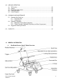
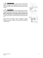
Raz Rehab Shower Chairs
AT Model
Dealer’s Manual
A guide to help authorized Raz dealers safely set-up
and adjust Raz Rehab Shower Chairs
20090122
SAFETY PRECAUTIONS
Failure to comply may cause injury or damage!
It is important that the Raz Rehab Shower Chair be properly assembled and
that all adjustments be made carefully. Please ensure that the user(s) and
attendant(s) have read the User’s Manual and thoroughly learn the safe
operation of the Raz Shower Chair. Up-to-date manuals are available online
at www.razdesigninc.com. For clarification of any section of this manual,
contact the Canadian distributor or the manufacturer.
IN CANADA
Dynamic Health Care Solutions
Bolton, Ontario Canada
905.951.8541 / 866.875.2877
[email protected]
IN THE U.S.A
Raz Design Inc.
Toronto, Ontario Canada
1.877.720.5678
[email protected]
CHAIR CLASSIFICATION BASED ON MAXIMUM USER WEIGHT
AT
300 lbs (136 kg)
SAFETY WARNINGS TO CONSIDER FOR RETAIL PURPOSES
Forward Stability
The front 5” casters on all models are equipped with dual-locks. The
step-on lever activates both the roll lock and the swivel lock. It is
essential that all casters on the shower chair be in the outward
position before engaging the locks for optimal forward and
lateral stability. If so equipped, disengage the optional directional
caster lock first before rotating the rear caster to the rearward position
and applying the casters’ dual-locks.
USERS MUST NOT lean forward while sitting in the Raz Shower
Chair as this may cause the chair to tip forward.
USERS MUST NOT wheel down a ramp without an attendant who
can hold onto the chair during the descent.
CASTER LOCKS ARE NOT BRAKES! Never use caster locks to
slow down the shower chair when descending inclines as this
could cause the chair to tip in the direction of travel.
Lateral Stability
USERS MUST NOT lean over the edge of a Raz Shower Chair as this
could cause the chair to tip.
USERS MUST NOT attempt to pick up objects from the floor by
leaning over and reaching – a reacher or assistance from others
should be employed.
USERS MUST NOT position the Raz Shower Chair on a side slope as
this could cause it to tip.
Raz AT Dealer’s Manual
20090122
2
Ramps and Other Inclines
Ramps and other surfaces that are not level (such as slopes into
wheel-in showers) must be tested with an attendant to ensure that
they don’t compromise the chair’s stability. A qualified healthcare
professional should be consulted to assist with this process.
DO NOT push or pull the Raz AT up or down an incline or ramp
that exceeds a 1:12 grade (5° slope).
DO NOT allow any user to be propelled (pushed or pulled) in a Raz
AT Shower Chair in any other manner than by an attendant.
ALWAYS CHECK THAT THE RAZ AT SHOWER CHAIR IS STABLE
BEFORE IT IS OCCUPIED BY ANY USER AT ANY TIME.
Immersion
The Raz Shower Chair is not designed to be used as a pool chair. Do
not immerse the shower chair in whole or in part, in water or any other
liquid. Damage to the shower chair components may result.
Transfers
The most dangerous part of using any shower chair is the transfer.
Since every chair has different stability characteristics, it is essential
to carefully review and test the transfer technique to ensure that the
procedure is safe. Test transfers should be performed with an
attendant who can prevent the chair from tipping or moving during the
transfer. If you feel that the transfers cannot be repeatedly performed
safely, contact a healthcare professional who is familiar with transfer
techniques and options. Individuals who have not learned proper
transfer skills must seek assistance during transfers and may require
the use of a mechanical lift.
Transferring onto a Raz AT Shower Chair – ALWAYS lock all four
casters in their outward position (front casters positioned in the
forward position/rear casters positioned to the rear) for maximum
chair stability. Caster locks DO NOT and CANNOT prevent the
casters from sliding, and the shower chair from moving, if the floor is
slippery. A slippery floor can be caused by dust, water, soap or any
substance that does not allow the casters to grip the floor securely.
Transfers should never be attempted with the shower chair
positioned on slippery surfaces. It is recommended that transfers
be performed on clean, dry, non-slippery surfaces. A fully-carpeted
surface is optimal. Be aware that area rugs and shower mats can
slide on floors and thereby present a hazardous surface.
DO NOT stand on any part of the frame of the Raz AT Shower Chair.
NEVER use the footplates to assist in transfers. This could cause
the chair to tip. The footrests should be swung to the side or removed
entirely during transfers to provide unobstructed access to the shower
chair.
Raz AT Dealer’s Manual
20090122
3
Tilt Function
ALWAYS check the tilt function and ensure both locking gas springs and release cable assemblies are
fully operational BEFORE the chair is occupied by the user.
ALWAYS use a pelvic strap as an additional safeguard for the user in a tilted position. A pelvic support
strap may be ordered as an option with the Raz AT.
DO NOT attempt to tilt an occupant if the attendant is physically incapable of safely and smoothly
operating the tilt function.
NEVER leave the user unattended in a tilted position in a Raz AT Shower Chair.
The Raz AT Shower Chair is NOT intended for use as a transportation device or a long-term seating
system.
IMPORTANT !
USERS SHOULD NEVER BE LEFT UNATTENDED IN A RAZ AT SHOWER CHAIR.
Raz AT Dealer’s Manual
20090122
4
DEALER'S MANUAL TABLE OF CONTENTS
Page
1.0
GENERAL INFORMATION
1.1
1.2
1.3
2.0
SET-UP
2.1
2.2
2.3
2.4
2.5
2.6
2.7
2.8
2.9
2.10
2.11
2.12
2.13
2.14
2.15
2.16
3.0
Raz Rehab Shower Chair AT Model Overview ........................................................... 6
Raz Rehab Shower Chair AT Model Specifications .................................................... 7
Tools Required for Set-up and Adjustments ............................................................... 7
Backrest Installation .................................................................................................... 8
Molded Seat Installation .............................................................................................. 8
Molded Headrest Installation....................................................................................... 9
Adjustable Footrest Installation ................................................................................... 9
Directional Caster Lock Installation ............................................................................. 9
Tilt Assist Pedal Installation....................................................................................... 10
Lateral Support Installation ....................................................................................... 10
2.7.1 Lateral Support Installation on Adjusta-Backs............................................... 10
2.7.2 Lateral Support Installation on Fixed Backs .................................................. 11
2.7.3 Extension Plate Installation ........................................................................... 12
Leg Adductor Installation........................................................................................... 12
Armrest Lock Installation ........................................................................................... 13
Molded Flat Armpad Installation................................................................................ 13
Molded Arm Trough Installation ................................................................................ 14
Chest Positioning Strap Installation........................................................................... 14
Pelvic Positioning Strap Installation .......................................................................... 14
H-Strap Installation.................................................................................................... 15
Heel Loop Installation................................................................................................ 15
Fastener Installation.................................................................................................. 15
ADJUSTMENTS
3.1
Backrest Adjustment ................................................................................................. 16
3.1.1 Backrest Angle Adjustment ........................................................................... 16
3.1.2 Adjustable Tension Back Upholstery Adjustment.......................................... 16
3.2 Molded Seat Adjustment ........................................................................................... 16
3.2.1 Molded Seat Depth Adjustment..................................................................... 16
3.2.2 Molded Seat Height Adjustment .................................................................... 17
3.3 Molded Headrest Adjustment .................................................................................... 17
3.4 Armrest Adjustment - Adjusta-Back Option Only ...................................................... 17
3.4.1 Armrest Height Adjustment............................................................................ 17
3.4.2 Armrest Angle Adjustment............................................................................. 18
3.5 Adjustable Footrest Adjustment ................................................................................ 18
3.6 Lateral Support Adjustment....................................................................................... 18
3.6.1 Lateral Support Height Adjustment................................................................ 18
3.6.2 Lateral Support Angle Adjustment................................................................. 18
3.7 Leg Adductor Adjustment .......................................................................................... 19
3.8 Molded Flat Armpad Adjustment ............................................................................... 19
3.9 Molded Arm Trough Adjustment................................................................................ 19
3.10 Chest Positioning Strap Adjustment.......................................................................... 19
3.11 Pelvic Positioning Strap Adjustment.......................................................................... 19
3.12 H-Strap Adjustment ................................................................................................... 19
Raz AT Dealer’s Manual
20090122
5
4.0
USE AND OPERATION
4.1
4.2
4.3
4.4
4.5
5.0
Tilt Function............................................................................................................... 20
Casters ...................................................................................................................... 20
Directional Caster Locks ........................................................................................... 20
Locking Armrests ...................................................................................................... 21
Lateral Supports ........................................................................................................ 21
CLEANING AND MAINTENANCE
5.1
5.2
5.3
Cleaning After Each Use ........................................................................................... 22
5.1.1 Commode Pan............................................................................................... 22
5.1.2 Molded Seat .................................................................................................. 22
Cleaning As Needed ................................................................................................. 22
5.2.1 Adjustable Tension Back Upholstery............................................................. 22
5.2.2 Frame, Armrests, Adjustable Footrests, and Other Components.................. 22
Suggested Cleaning Products................................................................................... 22
6.0
CONTACTS ....................................................................................................................... 23
1.0
GENERAL INFORMATION
1.1
Raz Rehab Shower Chair AT Model Overview
Raz AT Dealer’s Manual
20090122
6
1.2
Raz Rehab Shower Chair AT Model Specifications
SPECIFICATION
TILT FUNCTION
SEAT WIDTH
SEAT DEPTH
SEAT ADJUSTMENT
SEAT HEIGHT (front seat to floor)
CLEARANCE HEIGHT
Under Pan:
Under Frame:
FIXED BACK – Standard
Fixed Height., Flip-Up Armrests
RAZ AT
Gas spring assisted, up to 40o tilt range
18”
16” or 19”
Up to 2” (fore/aft)
21” – 25”
ADJUSTA-BACK – Optional
Adj. Ht./Angle, Flip-Up Locking Armrests
ARMREST HEIGHT
WIDTH BETWEEN ARMPADS
LATERAL SUPPORT
(adjustment range)
FOOTREST ADJUSTMENT
(from seat to footplate)
CASTER TYPE AND SIZE
OVERALL WIDTH
1.3
12½” – 16½”
17¾” – 21¾”
17” back height (Z505)
20” back height (Z506)
17” back height (Z510)
20” back height (Z515)
24” back height (Z520)
8½” (Z505)
9½” (Z506)
7” – 9½” (Z510)
8” – 10½” (Z515)
8” – 10½” (Z520)
18¾”
1¼” – 2½” offset
2” vertical
1” fore/aft
± 5° pad angle
16” – 20½” (Z705)
18” – 22½” (Z707)
Dual-locking 5” casters (x4)
22” (w/ std. armpad)
25½” (w/ Z715 armpad)
OVERALL LENGTH WHEN UPRIGHT
Without footrests:
With footrests:
OVERALL LENGTH WHEN TILTED
Without footrests:
With footrests:
WEIGHT CAPACITY
PRODUCT WEIGHT
41½“
51¼”
300 lbs.
65 lbs.
FRAME AND HARDWARE MATERIAL
Stainless Steel
33½”
43¼”
Tools Required for Set-up and Adjustments
Raz AT Dealer’s Manual
20090122
7
2.0
SET-UP
Backrest Installation
2.1
Tools needed: 5/32” hex key and a 7/16” wrench
1. Remove the Shower Chair from the shipping carton.
2. Lift the backrest to an upright position.
TIP: A Phillips screwdriver can be inserted through one of the plates
and back posts to temporarily fix the backrest in an upright position.
3. Insert an included 1¾” long, hex socket button head screw
with a washer through one of the three holes on the backrest
plate, then push the screw through the backrest frame tube.
NOTE: Select the middle hole for a 90o backrest angle, rear hole for
85o or front hole for a 95o backrest angle.
4. Attach to the other end of the screw a coved spacer, washer
and locknut as shown below.
5. Tighten the assembly until the end of the screw extends 1 or
2 threads beyond the nylon locknut.
6. Repeat steps 3 to 5 for other backrest plate.
WASHER
TOP VIEW OF BACKREST
ASSEMBLY
LOCKNUT
COVED SPACER
2.2
Molded Seat Installation
1. Ensure that the spring clips in the front seat brackets are in the unlatched position. To unlatch
the spring clips, squeeze each clip inward to unlatch the free end from the front seat bracket.
2. Slide the rear of the seat over the rear crosstubes as the front of the seat is lowered onto the
frame. Check to make sure that the rear seat brackets hook below the crosstubes.
3. Continue lowering the front of the seat until the front seat brackets nestle onto the front seat
support tubes.
4. Secure the seat in place by latching the spring clips. To latch the spring clips, squeeze each clip
inward while moving the free end towards the seat until the spring clips click into the seat
brackets around the front support tubes.
5. Reverse steps 1 to 4 to remove the seat from the frame.
1
Raz AT Dealer’s Manual
20090122
2
3
8
2.3
Molded Headrest Installation
Kit includes: Molded Headrest and post, a vertical “swan neck” support, a two-piece headrest mounting
clamp, a plastic tri-lobe (x2), a ¼”-20x1¼” hex head screw (x2), a ¼” washer (x2), and a ¼”-20 thin
locknut (x2)
Tools needed: an adjustable wrench
1. Remove the headrest, mounting clamp, and vertical support
from the accessory box.
2. Remove the ¼”-20 locknuts from the back of the black clamp.
3. Install the clamp on the rear crossbar by pushing the screws
with washers through the holes in the clamp and crossbar.
4. Replace the washers and nuts on the inside of the crossbar
and tighten the hex head screws to secure the clamp.
5. Insert the vertical “swan neck” support bar into the mounting
clamp on the chair backrest crossbar with the tri-lobe on the
vertical bar facing up and towards the front of the chair as
shown.
6. Tighten the bottom tri-lobe knob on the clamp securely.
7. Insert the headrest post into the bracket on the vertical support
and adjust the position to suit the users’ needs.
8. Tighten the top tri-lobe securely.
2.4
Adjustable Footrest Installation
Kit includes: Left and right footrests, comprised of a footplate and
extension tube connected to the hanger tube by a snap-pin
1. Remove wrapped footrests from the inner accessory box.
2. Lift the hanger tubes up from the footplates.
3. With the footplates directed in, place the footrest hanger tubes
into the receiving sleeves at the front of the commode frame. If
the support tubes are directed forward the pins on the tubes
will engage with grooves in the sleeves and lock in place.
2.5
Directional Caster Lock Installation
A Directional Caster Lock can be added to one caster on the Raz AT
Shower Chair to facilitate linear movement of the chair.
Kit includes: a directional caster lock subassembly
Tools needed: 5/32” hex key and an adjustable wrench
1. Remove the directional caster lock from the accessory box.
2. Remove the two loosened top screws, locknuts, and the
plastic spacer between the lock plates.
3. Starting under the tube near the rear right wheel, slide the
directional caster lock up into place around the chair frame.
NOTE: The directional caster lock latch must be facing towards the
front of the chair to properly engage with the caster.
4. Move the caster lock back along the frame towards the caster.
Check the position by engaging the directional caster lock and
then the caster’s dual-lock. The dual-lock should be able to flip
up without hitting the directional lock guide when it is in the
downwards/activated position.
5. Replace the plastic spacer above the frame tube and between
the two lock plates.
6. Return and tighten the screws and locknuts.
7. Test the directional caster lock for interference.
Raz AT Dealer’s Manual
20090122
9
2.6
Tilt Assist Pedal Installation
An optional Tilt Assist Pedal can be ordered to help attendants tilt the
Raz AT Shower Chair. The Tilt Assist Pedal can be mounted on either
the left or right side of the chair depending on the attendant’s
preference.
Kit includes: a Tilt Assist Pedal and two clear plastic shims
Tools needed: 5/32” hex key and a 7/16” wrench
1. Remove the tilt assist pedal from the accessory box.
2. On the preferred side of the chair for the tilt assist pedal,
remove the locknut and washer from the bottom screw nearest
to the back of the chair.
NOTE: The Tilt Assist Pedal can be mounted on either the left or right
side of the chair depending on the attendant’s preference.
3. Remove the screw from the frame tube and backrest mounting
plate as shown.
4. Remove the black cap from the back horizontal frame tube, this
cap may be discarded.
5. Insert the tilt assist pedal into the tube as shown with the black
friction strip facing up.
6. Replace the screw through backrest mounting
plate,
chair
frame tube, and tilt assist pedal post.
7. Secure with the washer and locknut.
8. Test the Tilt Assist Pedal to ensure proper installation.
TIP: If the Tilt Assist Pedal fits loosely inside the frame tube, remove
the tilt assist pedal post and adhere one (or both) of the included
plastic shims to either side of the horizontal pedal post. Take care to
not cover the hole on the post.
2.7
Lateral Support Installation
One or two Lateral Supports may be mounted on any Raz AT Model.
An extension plate can be ordered as an option to attain better
positioning of the Lateral Support Pad.
2.7.1 Lateral Support Installation on Adjusta-Backs
Kit includes (for each side): a mounting post, one 3/8”-16x2¾” button
head cap screw, a 3/8”-16x1¼” button head cap screw, a 3/8”
washer (x2), 3/8”-16 locknut (x2), a ¼”-20x¾” screw (x2), a ¼”
washer (x2), a lateral L bracket, and a Lateral Support Pad
Tools needed: ¼” hex key, 3/8” hex key, and a 9/16” wrench
1. Remove the lateral sub-assembly kit from the accessory box.
2. Separate the left armrest assembly from the left armrest
weldment on the back frame by unscrewing both button head
cap screws.
3. Replace the screws with longer screws from the lateral subassembly kit. (A 3/8”-16x2¾” screw should be inserted in the
arm pivot position and the 3/8”-16x1¼” screw in one of the
three anchor positions)
4. Replace the armrest assembly against the armrest weldment at
the desired height. The new screws should protrude more from
the armrest weldment than the previous ones.
5. Position the left mounting post on the inside of the left armrest
weldment. Make sure that the orientation of the mounting post
is such that the tab with the holes is up and facing forward on
the outside of the chair as shown.
Raz AT Dealer’s Manual
20090122
Two screws
10
6. If the desired armrest height is high enough, both screws from
the armrest assembly may be used to secure the lateral
mounting post to the chair with the locknuts provided. In the
case that the armrest assembly is mounted low on the armrest
weldment the pivot plate can be secured at the bottom with the
screw from the armrest assembly and the mounting post should
be anchored to the weldment with the 3/8”-16x1¼” screw from
the lateral kit as high on the armrest weldment as possible.
7. Secure the mounting post at the desired height with the 3/8”
washers and 3/8”-16 locknuts provided in the lateral support kit.
8. Take the left lateral support pad assembly (with the blue arrow
decal pointing up and out) and connect it to the outside of the
lateral mounting post by securing two ¼”-20x¾” screws and ¼”
washers into the threaded holes on the mounting post.
9. Secure all fasteners and verify that the lateral support can
rotate 270˚ without hitting other components on the chair. The
armrest must be able to raise and lower without interference
when the lateral support pad is in both the forward and rear
positions.
10. Repeat steps 2 to 9 for the right lateral support if required.
Three screws
2.7.2 Lateral Support Installation on Fixed Backs
Kit includes (for each side): a mounting post, 3/8”-16x2¼” button head
cap screw, a 3/8”-16x1” button head cap screw, 3/8” washers (x8),
3/8”-16 locknuts (x2), ¼”-20x¾” screws (x4), ¼”-20 locknuts (x2),
¼” washers (x6), a fixed back lateral adapter plate, a lateral Lbracket, and a Lateral Support Pad
Tools needed: ¼” hex key, 3/8” hex key, and a 9/16” wrench
1. Remove the lateral sub-assembly kit from the accessory box.
2. Separate all of the hardware from the fixed back lateral
adapter plate.
3. Unscrew and remove the left armrest pivot button head cap
screw.
4. Leaving the armrest and spacers in position on the chair,
install the 3/8”-16x2¼” screw and a 3/8” washer included in the
lateral kit into the left armrest pivot position.
5. Insert an included 3/8”-16x1” screw and a washer into the hole
on the armrest weldment which lies directly below the armrest
pivot screw.
6. Mount the fixed back lateral adapter plate in the orientation
shown, onto the two installed screws on the inside of the
armrest weldment.
7. Secure both screws with a 3/8” washer and 3/8”-16 locknut.
8. Insert two remaining ¼”-20x¾” screws with ¼” washers into
the exposed holes on the fixed back lateral adapter plate and
install the mounting post on these screws. Make sure that the
orientation of the mounting post is such that the tab with the
holes is up and facing forward on the outside of the chair.
9. Secure the mounting post at the desired height with ¼”
washers and ¼”-20 locknuts provided.
10. Take the left lateral support pad assembly (with the blue arrow
decal pointing up and out) and connect it to the outside of the
lateral mounting post by screwing two ¼”-20x¾” screws and
¼” washers into the threaded holes on the mounting post.
11. Secure all of the fasteners and verify that the lateral support
Raz AT Dealer’s Manual
20090122
11
can rotate 270° without hitting other components on the chair.
The armrests must be able to raise and lower without
interference when the lateral support pad is in both the forward
and rear positions.
12. Repeat steps 2 to 11 for the right lateral support if required.
2.7.3 Extension Plate Installation
Kit includes (for each side): a lateral support extension plate,
¼”-20x¾” screw (x2), ¼”-20 thin locknut (x2)
Tools needed: 5/32” hex key and a 7/16” wrench
1. Disconnect one lateral support pad from the L-bracket (on the
mounting post) by removing both sets of screws and locknuts.
2. Attach the extension plate behind the L-bracket using the
previously installed ¼”-20x¾” screws and ¼”-20 thin locknuts.
3. With the additional screws provided in the kit, connect the
lateral support pad to the extension plate and secure it with the
locknuts.
4. Repeat steps 1 to 3 if an extension plate was ordered for the
other lateral support.
2.8
Leg Adductor Installation
Kit includes (for each side): an adductor pad, a mounting post, frame clamp (x2), a plastic tri-lobe, a
mounting plate, a two-piece adductor clamp, ¼”-20x¾” hex head screw (x2), ¼”-20x1¼” hex head
screw (x2), ¼”-20x1” hex head screw (x2), ¼” washer (x14), ¼”-20 locknut (x4), 3/8” spacer (x2)
Tools needed: a 7/16” wrench and an adjustable wrench
1. Loosen both outer ¼”-20x1¼” hex head screws on the
mounting plates until the two clamps can fit around the
horizontal tubes on the seat frame. Ensure that the clamps
latch onto the frame from above it, not below.
2. Locate the adductor plate on one horizontal frame tube towards
the front of the chair to a position, near the footrest receivers,
that suits the users’ needs.
3. Secure the frame clamps in place by tightening the screws.
4. Attach an adductor pad to a mounting post by removing both
washers and nuts on the pad insert tab.
5. Position the end of the mounting post against the adductor pad
insert tab and align the holes.
6. Secure the pad to the post by fastening the ¼”-20x¾” hex head
screws with the two sets of washers and locknuts.
7. Loosen the tri-lobe knob at the clamp.
8. Insert the mounting post into the receiver clamp on the outside
of the mounting plate now located on the chair frame. Tighten
the tri-lobe knob when the adductor pad is located at the
desired height for the user.
9. Repeat steps 3 to 8 for the other side of the chair if required.
Tighten all hardware securely and test the Leg Adductors
before use.
Raz AT Dealer’s Manual
20090122
12
2.9
Armrest Lock Installation
Locking armrests are pre-installed on a shower chair ordered with the Adjusta-Back option. In the case
that a Fixed Back (standard) is requested in the order, flip-up armrests are standard and an optional
locking armrest kit must be ordered and installed by the dealer. To maintain the integrity of the
fasteners, this operation is best performed without removing the installed flip-up armrests.
Kit includes: two latch plates, left & right springs, 5/16”-18x¾” button head cap screw (x2), 5/16” washer
(x2), 5/16”-18 locknut (x2)
Tools needed: 3/16” hex key and an adjustable wrench
1. Take a 5/16”-18x¾” screw and insert a 5/16” washer onto it.
2. Insert the screw and washer into the hole in an armrest fin.
3. Install the right armrest latch spring 90° bend end into the
small hole on the armrest support fin with the 90° bend facing
towards the front of the armrest, slide the spring opening over
the screw on the inside of the armrest fin as shown.
4. Stretch the spring hook clockwise and install the latch plate over the screw and spring with the
stop facing towards the outside of the arm.
5. Release the spring, and the hook section will rest on the upper edge of the armrest latch.
6. Secure the assembly with a 5/16”-18 locknut.
7. Tighten the locknut only until the screw threads penetrate the nylon in the locknut. Do not overtighten, as the spring mechanism will not rotate freely.
8. Repeat steps 2 to 7 for the left armrest.
4
5
6
2.10 Molded Flat Armpad Installation
Kit includes: flat armpads (x2), 10-32 flange locknuts (x4), and 1032x1⅜” screws (x4)
Tools needed: a Phillips screwdriver
1. Unscrew the 10-32x1⅜” screws from the 10-32 flange locknuts
in the metal insert on the bottom of the left armpad.
2. Push one screw up through the bottom and then the top of the
hole farthest from the chair on the left armrest post.
3. Position one of the nuts (in the track on the armpad insert)
over this screw and secure it loosely.
NOTE: When positioned over the armrest post, the left armpad should
be mounted so that the centre of the pad is located outside of the
chair’s perimeter. Failure to do so may inhibit the flip function of the
armrest.
4. With this screw in place, lift the armrest post to an upright
position, thereby allowing the second nut located in the insert
track to slide down to the bottom of the armpad.
5. Insert another screw through the other hole on the post.
6. Slide the armrest up until the loose locknut in the track lines up
with the screw. Secure the screw loosely.
7. Slide the armpad to the desired position on the armrest post,
making sure that the position of the armpad does not impede
the flip function of the armrest.
8. Tighten the screws fully and test the armrest prior to use.
9. Repeat steps 2 to 8 for the right armpad.
Raz AT Dealer’s Manual
20090122
13
2.11 Molded Arm Trough Installation
Kit includes: Molded Arm Troughs (x2), 10-32 flange locknuts (x4),
and 10-32x1⅜” screws (x4)
Tools needed: a Phillips screwdriver
1. Unscrew the 10-32x1⅜” screws from the 10-32 flange locknuts
in the metal insert on the bottom of the left arm trough.
2. Push one screw up through the bottom and then the top of the
hole farthest from the chair on the left armrest post.
3. Position one of the nuts (in the track on the arm trough insert)
over this screw and secure it loosely.
NOTE: When positioned over the armrest post, the left arm trough
should be mounted so that the centre of the pad is located outside of
the chair’s perimeter. Failure to do so may inhibit the flip function of
the armrest.
4. With this screw in place, lift the armrest post to an upright
position, thereby allowing the second nut located in the insert
track to slide down to the bottom of the arm trough.
5. Insert a second screw through the remaining hole on the
armrest post.
6. Slide the arm trough up until the loose locknut in the track on
the arm trough insert lines up with the screw. Secure this
screw loosely.
7. Slide the arm trough to the desired position on the armrest
post making sure that the position of the arm trough does not
impede the flip function of the armrest.
8. Tighten the screws fully and test the arm trough prior to use.
9. Repeat steps 2 to 8 for the right arm trough.
2.12 Chest Positioning Strap Installation
A one-piece Chest Positioning Strap can be attached to any Raz
Model. The back upholstery includes loops intended as strap guides.
Kit includes: a one-piece chest positioning strap with a Velcro closure
1. Remove the chest strap from the accessory box.
2. Insert one side of the strap through both loops sewn into the
back upholstery on the shower commode chair.
3. With the user seated in the chair, thread one end of the strap
through the D-ring on the other end of the chest strap.
4. Secure the strap in front of the user with the Velcro closure.
2.13 Pelvic Positioning Strap Installation
A two-piece Pelvic Positioning Strap can be ordered with the shower
chair and can be attached to any Raz Model. This installation should
be performed with care as the user’s safety is dependent on secure
straps.
Kit includes: two straps with “double D” rings and a plastic buckle
1. Take both straps and both DD-rings out of the accessory box.
2. Weave the loose end of one strap through the DD-ring and
slide the DD-ring several inches from the end.
3. Feed the strap through the slot in the backrest mounting plate
– from the inside to the outside and then weave the loose end
back through the DD-ring.
4. Repeat steps 2 and 3 for the other side of the strap.
5. Adjust the DD-ring and tighten the pelvic strap as needed.
6. Pull tightly on each strap to ensure that they are secured
properly prior to use.
Raz AT Dealer’s Manual
20090122
14
2.14 H-Strap Installation
An H-Strap can be attached to the footrests on any Raz model.
Kit includes: a one-piece H-Strap with a Velcro closure
1. Remove the H-Strap from the accessory box.
2. With the Velcro facing towards the chair, center the strap
horizontally between both footrest hanger tubes and wrap the
strap around the tubes until the loop Velcro engages with the
hook Velcro.
2.15 Heel Loop Installation
Heel Loops can be attached to one or both footrests on any Raz
Shower Chair, they provide added support and comfort for the user
especially when in a tilted position.
Kit includes: Heel Loop (x2), a ¼”-20x1¾” button head cap screw (x2),
a ¼”-20 thin locknut (x2), and a 1¼” spacer (x2)
Tools needed: 5/32” hex key, 7/16” wrench, and a drill with a ¼” bit
1. Remove the heel loop kit from the accessory box.
2. Remove the left footrest from the chair if already installed.
Take note of the edge of the footplate that is located the
closest to the chair when installed.
3. Turn the left footrest upside down to expose the underside of
the footplate.
4. Locate the pilot hole furthest away from the footrest hanger
tube on the edge of the footplate that will be closest to the
chair once mounted. Selection of the proper pilot hole is very
important prior to drilling.
5. Drill through the footplate using a drill with a ¼” drill bit, using
the pilot hole on the underside of the footplate as a guide.
6. Slide the large opening of one heel loop over the footrest
hanger tube until it sits against the footplate. It is more
comfortable for the user if the cut edges of the strap are facing
towards the chair (away from the user’s feet).
7. Slide a plastic spacer onto a ¼”-20x1¾” button head cap
screw and insert the bolt and spacer in through the top of the
small slot of the strap and into the new hole in the footplate.
8. Secure the screw and strap in place with a ¼”-20 thin locknut
on the underside of the footplate using a hex key and wrench.
9. Repeat steps 2 to 8 for the right heel loop if required.
2.16 Fastener Installation
All fasteners should be installed securely to ensure that they are snug
and do not pose any risks to the end user. Locknuts that are removed
for any reason should be replaced rather than re-used. The user is
advised to ensure that an overall check of the fasteners and all
components of the Raz Shower Chair be properly assessed by their
dealer at least once per year.
Raz AT Dealer’s Manual
20090122
15
3.0
ADJUSTMENTS
IMPORTANT !
ADJUSTMENTS SHOULD NEVER BE ATTEMPTED WITH THE USER IN THE CHAIR.
3.1
Backrest Adjustment
3.1.1 Backrest Angle Adjustment
Tools needed: 5/32” hex key and a 7/16” wrench
1. Loosen and remove the locknuts, washers, and coved spacers
inside both vertical backrest frame tubes.
2. Remove the middle 1¾” screws and washers from the vertical
backrest frame tubes.
3. Rotate the backrest to one of the 3 positions on the backrest
mounting plates.
NOTE: Select the middle hole for a 90o backrest angle, rear hole for
85o or front hole for a 95o backrest angle.
4. With the backrest in place insert the screws and washers
through the selected holes on the backrest plates, and then
push them through the frame tubes.
5. Fasten the other end of the screws with coved spacers,
washers and locknuts.
6. Tighten the assembly with a hex key and wrench until the end
of the screw extends 1 or 2 threads beyond the nylon locknut.
3.1.2 Adjustable Tension Back Upholstery Adjustment
In order to adjust the back upholstery of the backrest each strap can be tightened or loosened in the
buckles to achieve a wide range of positions. For example the second and third straps from the bottom
can be tightened to create more pronounced support in the lumbar area of the back. The looser the
straps of the back upholstery; the more the fabric will sling-in, creating more contact with the user.
3.2
Molded Seat Adjustment
3.2.1 Molded Seat Depth Adjustment
The seat has approximately 2” of fore/aft adjustment.
Tools needed: #2 Phillips screwdriver
1. Release the seat by squeezing the spring clips that lock the
front seat brackets to the chair frame.
2. Remove the seat by lifting up on the front edge and sliding the
seat forward and away from the chair.
3. Loosen (do not remove) the eight screws attaching the front
and rear seat brackets to the underside of the seat.
4. Return the seat to the chair frame, nestling the front seat
clamps onto the front support tubes.
5. Slide / jiggle the seat to the desired position.
6. Tighten the screws just enough to hold the front seat clamps in
place, making sure the seat is positioned evenly and square to
the frame.
7. With the seat on the chair, slide the rear brackets back until
they make firm contact with the rear crosstube, tighten the
screws to hold the brackets in place.
8. Remove the seat (steps 1 & 2) and tighten all eight screws.
9. Secure the seat to the chair frame by following the seat
installation steps in section 2.2.
Raz AT Dealer’s Manual
20090122
16
3.2.2 Molded Seat Height Adjustment
To change the seat-to-floor height on a Raz AT model, the chair is
raised from the wheel base at the seat posts on both sides of the
chair.
Tools needed: 1/4” hex key and an adjustable wrench
1. Remove screws from the left and right seat posts on the chair.
2. Remove the screws from both gas springs under the seat.
3. Lift the chair to the height required for the user.
4. Adjust the seat to a position level to the ground.
5. Return the screws to their positions in the seat posts and gas
springs on the chair. Note: The screw on the gas spring will
need to be relocated from its previous position in order to
achieve a level seat.
IMPORTANT !
INCREASING THE SEAT HEIGHT AND INCREASING THE BACKREST ANGLE WILL DECREASE
REARWARD STABILITY. IT IS ESSENTIAL THAT A STABILITY CHECK BE PERFORMED AFTER
ANY OF THESE ADJUSTMENTS ARE MADE.
Molded Headrest Adjustment – Adjusta-Back Option Only
3.3
Tools needed: 5/32” hex key
1. Loosen the bottom tri-lobe knob and adjust the vertical “swan
neck” support in order to achieve headrest height adjustment.
2. Loosen the top tri-lobe knob and adjust the headrest post
horizontally for a fore/aft change in position.
3. To change the angle of the headrest itself, loosen (do not
remove) the three screws on the back of the molded headrest.
Rotate the headrest around the end of the headrest mounting
post to suit users’ needs and tighten the screws to secure the
desired position.
4. Ensure that all knobs and screws are tightened securely for
the user’s safety.
3.4
Armrest Adjustment – Adjusta-Back Option Only
3.4.1 Armrest Height Adjustment
The armrests are adjustable in height within a 3” range, in ½”
increments on the Adjusta-Back Option only. The armrests can be
adjusted in height from 7 ½” to 9 ½” with the 17” Height Adjusta-Back,
and from 8 ½” to 10 ½” with the 20” and 24” Height Adjusta-Back.
Tools needed: 3/16” hex key, and a ½” wrench
1. Loosen and remove the lower locknut.
2. Loosen and remove the top locknut.
3. Keeping the armrest and armrest pivot plate assembly
together, move the unit up or down on the armrest support
weldment depending on the user’s needs.
4. Replace the locknut onto the top screw.
5. Replace the locknut onto the bottom screw.
6. Tighten screws and locknuts at the top and bottom.
7. Repeat steps 1 to 6 for other armrest.
Raz AT Dealer’s Manual
20090122
17
3.4.2 Armrest Angle Adjustment
The armrest angle can be adjusted up 5° or down 5° if the backrest
angle is adjusted from the 90° factory position.
Tools needed: 3/16” hex key and a ½” wrench
1. Loosen and remove the screw, washer, and locknut on the
bottom of the armrest pivot plate.
2. Keeping the upper screw in place, rotate the armrest assembly
until the preferred position is reached by aligning one of the 3
holes (arranged in a triangle) on the armrest pivot plate with
the holes on the armrest support weldment.
3. Replace the 3/8”x¾” screw and 3/8” washer into the preferred
position on the armrest pivot plate, and finish with the locknut.
4. Tighten the screw and locknut.
5. Repeat steps 1 to 4 for the other armrest.
3.5
Adjustable Footrest Adjustment
1. Remove a plastic snap-pin from one footrest hanger tube.
2. Adjust the footplate extension tube vertically to achieve the
desired height in the footrest hanger tube.
3. Insert the snap-pin through the footrest hanger tube and the
extension tube. Ensure that the snap-pin is completely through
the tube and that the grey plastic clip is snapped securely
around the outside of the hanger tube.
4. Repeat steps 1 to 3 for the other footplate.
3.6
Lateral Support Adjustment
3.6.1 Lateral Support Height Adjustment
Tools needed: ¼” hex key, 3/8” hex key, and a 9/16” wrench
1. Remove the lateral pad from the mounting post by removing
the two screws and washers from the threaded holes on the
mounting post.
2. Remove the locknuts from the armrest assembly and leaving
the armrest in the same location, change the height of the
lateral mounting post to the needed height.
NOTE: An additional screw provided in the lateral sub-assembly kit
may be required depending on the required locations of the armrest
and lateral pad. The mounting post must always be anchored into the
top hole on the armrest weldment on the chair.
3. Replace and tighten the locknuts onto the armrest assembly
screws.
3.6.2 Lateral Support Angle Adjustment
Tools needed: 5/32” hex key and a 7/16” wrench
1. Loosen each set of screws at the desired location for lateral
support rotation and shift the brackets against one another.
2. Tighten the screws once the position and angle is achieved.
3. Verify that the lateral support can rotate 270° without hitting
other components on the chair. The armrests must be able to
raise and lower without interference when the lateral support
pad is in both the forward and rear positions.
Raz AT Dealer’s Manual
20090122
18
3.7
Leg Adductor Adjustment
Tools needed: a 7/16” wrench and an adjustable wrench
1. Loosen (do not remove) both outer ¼”-20x1¼” hex head
screws on the mounting plates, relocate the adductor plate on
the horizontal frame tube to a position that suits the users’
needs.
2. Loosen the tri-lobe knob and adjust the mounting post up or
down to the desired height.
3. Ensure that all knobs and screws are tightened securely prior
to use.
4. Repeat steps 1 to 3 if adjustments are required for a second
leg adductor.
3.8
Molded Flat Armpad Adjustment
Tools needed: a Phillips screwdriver
1. Loosen the 10-32x1⅜” screws from the 10-32 flange locknuts
in the metal insert on the bottom of the armpads.
2. Slide the armpads to the desired position on the armrest posts,
making sure that the positions of the armpads do not impede
the flip function of the armrests.
3. Tighten the screws fully and test the armrests prior to use.
3.9
Molded Arm Trough Adjustment
Tools needed: a Phillips screwdriver
1. Loosen the 10-32x1⅜” screws from the 10-32 flange locknuts
in the metal insert on the bottom of the arm troughs.
2. Slide the arm troughs to the desired position on the armrest
posts, making sure that the positions of the arm troughs do not
impede the flip function of the armrests.
3. Tighten the screws fully and test the armrests prior to use.
3.10 Chest Positioning Strap Adjustment
1. Open the Velcro on the chest strap.
2. Tighten or loosen the strap around the user as needed.
3.11 Pelvic Positioning Strap Adjustment
1. Loosen both straps through the “double D” ring (DD-ring) on
one side of the pelvic strap.
2. Adjust by pulling or pushing the outer end of strap in or out of
the DD-ring.
3. Repeat step 2 for the other side of the strap.
4. Pull tightly on each strap to ensure that it is secured properly.
3.12 H-Strap Adjustment
1. Disconnect the Velcro from the back of the H-strap and adjust it
to sling or tighten the H-strap to suit the users’ needs.
2. Press firmly on the Velcro to secure the strap prior to use.
Raz AT Dealer’s Manual
20090122
19
4.0
USE AND OPERATION
4.1
Tilt Funtion
The Raz AT Shower Commode tilts up to 40o to provide comfort and
relieve pressure for the user. Two gas assist springs facilitate this
action and make the tilt smooth for the user and facilitated for the
attendant. To tilt the chair the attendant must squeeze both tilt triggers
and move the chair into the desired angle. To lock the chair in place
the triggers are simply released. Directly after purchase the triggers
and springs may seem stiff. This stiffness is normal and diminishes
with use. Some attendants have a need for a tilt assist pedal, which
enables the attendant to place one foot on the lever to facilitate tilting.
The tilt function must only take place when the casters are locked.
NOTE: When the chair is mounted at the lowest height setting the
maximum potential tilt angle is 40o. The higher the chair is set, the
fewer degrees the chair can be tilted back. (With a seat-to-floor height
of 25” the chair can be tilted back 36o)
IMPORTANT !
ANY ATTENDANT MUST BE FAMILIAR WITH PROPER TILTING TECHNIQUES PRIOR TO
ASSISTING A USER IN THE SHOWER COMMODE. A PELVIC STRAP IS RECOMMENDED FOR
ANY USER AS AN EXTRA SAFETY PRECAUTION.
4.2
Casters
Each Raz Shower Chair caster is equipped with a dual-lock feature
which stops the caster from swivelling and rolling simultaneously. To
activate the dual-lock, step on the end of the caster brake lever until it
latches in the on position. To deactivate the dual-lock, step on the
raised end of the dual-lock until it latches in the off position.
4.3
Directional Caster Lock
The flip-down Directional Caster Lock keeps one rear caster aligned
in a forward direction. This feature is provided to facilitate the pushing
of the chair by reducing unwanted sideways movement. Closequarters manoeuvrability may be easier with the directional lock in the
“off” (upwards) position. To engage the directional lock, first ensure
the caster dual-locks are not activated and that each caster can swivel
and roll freely. Pull the Raz AT rearward until the rear casters swivel
to their forward positions, directly under the frame tube. Flip the
directional lock guide latch down to its on position so that it cradles
and holds the caster in the forward position. If the caster is not
perfectly in-line with the frame, the spring-loaded latch, once
activated, will engage if the rear caster is slowly swung around. To
disengage the directional lock, flip the spring-loaded latch up, to its
“off” position.
ALWAYS release the directional lock and swivel all four casters to
their outward position for maximum stability before transferring or
tilting a user.
Raz AT Dealer’s Manual
20090122
20
4.4
Locking Armrests
To flip up the locking armrests, release the arm lock by lifting the
trigger underneath the armrest tube and lift up the armrest. This
feature is included with the Adjusta-Back Option only. An optional
locking armrest latch can be ordered to equip a fixed back with locking
armrests.
4.5
Lateral Supports
The Raz Shower Chair may be fitted with optional lateral supports.
The lateral support pads lock in the forward position and in the
rearward position (behind the backrest). To release a lateral support
pad from either position, grip the pad assembly at the blue arrow
decal and lift straight up. Once released, rotate the lateral pad to the
forward or rearward position and press lightly at the decal area to lock
the pad in place. Check to ensure the lateral is locked in place before
use.
Lateral supports are designed to assist in maintaining an upright
posture in the Raz Shower Chair. Adjustments (up/down,
medial/lateral) should be made by the dealer so that the pads are
positioned safely.
Raz AT Dealer’s Manual
20090122
21
5.0
CLEANING AND MAINTENANCE
5.1
Cleaning After Each Use
5.1.1 Commode Pan
1. Remove the commode pan and empty contents.
2. Wash the pan with a multi-purpose disinfectant cleaning solution. Use a scrub brush if needed.
3. Rinse well before storage or re-use.
NOTE: A soapy hot water wash followed by a disinfectant spray can be substituted for a multi-purpose
disinfectant cleaning solution.
5.1.2 Molded Seat
1. Spray with a multi-purpose disinfectant cleaner and scrub with a soft brush as required.
2. Rinse with a water spray before storage or re-use.
DO NOT IMMERSE the seat in water or cleaning solutions.
3. For a more thorough cleaning, remove the seat from the shower chair to allow better access to
the underside of the seat and around the opening of the seat.
5.2
1.
2.
3.
4.
5.
Cleaning As Needed
5.2.1 Adjustable Tension Back Upholstery
Remove the plastic buckles and tri-glides from the back upholstery straps, paying attention to
how the straps are wound through each component as they are removed.
Remove the back upholstery from the back frame and machine wash with a mild detergent in
warm water on a normal or gentle wash cycle. Include other strap accessories such as the Hstrap, pelvic and chest positioning straps.
Install the back upholstery and other positioning accessories on the chair and allow to dry.
DO NOT dry the back upholstery in a clothes dryer or damage to the upholstery may occur.
Assemble all plastic buckles and tri-glides onto straps.
Adjust the straps to the desired tension.
5.2.2 Frame, Armrests, Adjustable Footrests, and Other Components
1. Spray the frame and components with a multi-purpose disinfectant cleaner, scrub with a soft
brush and rinse with water.
2. If necessary, spray the frame and components with a diluted (10 parts water to 1 part solution)
calcium/lime remover, scrub with a soft brush and rinse thoroughly with water.
DO NOT mix a calcium/lime removal solution with any other liquid or toxic fumes may occur.
It is recommended to the user that a qualified Raz dealer check over all fasteners and subassemblies on
a continuing basis or if there is cause for concern to the shower chair’s performance.
It is highly recommended that any rinsing of Raz Shower Chair components occur in a well drained area
with an industrial steam cleaner (e.g. Intersteam) or a commercial pressure washer.
Several times each year the shower chair and its components should be wiped down with a diluted
calcium/lime removal solution to reduce deposits, followed by a hot water rinse.
To reduce the risk of mildew buildup the entire chair should be wiped down with a soft dry cloth after the
final rinse and before storage or use.
5.3
Suggested Cleaning Products
Task
Recommended Products
General Cleaning
Antibacterial Detergent
Tuberculocidal Surface Cleaner and
Intermediate Level Disinfectant
Accel TB (Virox Technologies Inc.), SepteFX
7D-11 (Titan Worldwide Inc.)
Calcium and Lime Deterrent
CLR Outdoor Furniture Cleaner
Raz AT Dealer’s Manual
20090122
22
IMPORTANT !
DO NOT USE ABRASIVE SCRUBBING POWDERS OR SCOURING PADS ON THE RAZ SHOWER
CHAIR.
DO NOT SUBMERGE THE RAZ SHOWER CHAIR IN WATER.
RINSE THOUROUGHLY AFTER CLEANING TO ENSURE THAT ANY SOAP OR DETERGENT
RESIDUE IS REMOVED.
DO NOT USE CLEANING PRODUCTS WITHOUT CONSULTING THE PRODUCTS’ INSTRUCTIONS
AND TAKING APPROPRIATE PRECAUTIONS FOR HUMAN EXPOSURE TO CHEMICALS.
6.0
CONTACTS
It is important that the Raz Rehab Shower Chair be properly assembled and all adjustments be made
carefully. Up-to-date manuals can be downloaded from www.razdesigninc.com. For clarification of any
section of this manual, contact the Canadian distributor or manufacturer.
IN CANADA
Dynamic Health Care Solutions
Bolton, Ontario Canada
905.951.8541 / 866.875.2877
[email protected]
Raz AT Dealer’s Manual
20090122
IN THE U.S.A
Raz Design Inc.
Toronto, Ontario Canada
1.877.720.5678
[email protected]
23