1
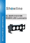
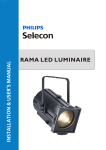
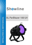
SL ePAR 180 LED Luminaire
www.Philips.com/Showline
website
SL ePAR 180 User’s Manual
24-004-3564-00 Rev1.0
SL ePAR 180 LED Luminaire installation & User’s Manual
2013 Philips Group. All rights reserved.
Installation & User’s Manual
SL ePAR 180 LED Luminaire
You must have access to a mains circuit breaker or other power disconnect device
mains circuit breaker off before installation. Installing the device with power on may expose you to
Additional Resources for DMX512
For more information on installing DMX512 control systems, the following publication is available for purchase
from the United States Institute for Theatre Technology (USITT), "Recommended Practice for DMX512: A Guide
for Users and Installers, 2nd edition" (ISBN: 9780955703522). USITT Contact Information:
USITT
315 South Crouse Avenue, Suite 200
Syracuse, NY 13210-1844
Phone: 1.800.938.7488 or 1.315.463.6463
www.usitt.org
Showline Limited Two-Year Warranty
Showline offers a two-year limited warranty of its luminaires against defects in materials or workmanship from the
date of delivery. A copy of the Showline two-year limited warranty containing specific terms and conditions can be
obtained by contacting your local Showline office.
Installation & User’s Manual
SL ePAR 180 LED Luminaire
TABLE OF CONTENTS
Showline Offices
IMPORTANT INFORMATION
Warnings and Notices
Additional Resources for DMX512
Showline Limited Two-Year Warranty
TABLE OF CONTENTS
PREFACE
About this Manual
Included Items
Accessories
SL ePAR 180 LED LUMINAIRE OVERVIEW
SL ePAR 180 LED Luminaire Components
Common Luminaire Components
LCD Display / Menu System
INSTALLATION AND SET UP
Power Requirements
Connecting Power
Connecting to the DMX512 Network
Mounting Luminaire
Floor Mounting
Truss/Hanging Applications
OPERATION AND PROGRAMMING
LCD Display and Menu System
SL ePAR 180 LED Luminaire
LCD Display and Menu System Operation
1
1
1
3
3
3
4
4
5
5
6
6
7
7
8
8
8
9
SL ePAR 180 LED Luminaire Menu Tree
11
Dimming Curve Selection
Master / Slave Operational Mode
12
13
DMX CONTROL
SL ePAR 180 LED Luminaire DMX Mapping
16-Bit Mode
8-Bit Mode
HSIC Mode
DMX Timing Channel Detail
RDM PARAMETER IDs
SL ePAR 180 LED Luminaire RDM Parameter IDs
CLEANING AND CARE
Special Cleaning and Care Instructions
Front Lens Cleaning
Service and Maintenance
Accessories
TECHNICAL SPECIFICATIONS
Operational Specifications
Luminaire Dimensions
2
Inside Front Cover
Table of contents
14
14
16
19
19
29
29
29
29
29
31
32
SL ePAR 180 LED Luminaire
Installation & User’s Manual
PREFACE
1.
About this Manual
The document provides installation and operation instructions for the following products:
SL ePAR 180 LED Luminaire
Please read all instructions before installing or using this product. Retain this manual for future reference.
Additional product information and descriptions may be found on the product specification sheet.
Note: The SL ePAR 180 LED Luminaire is universal voltage 100 to 240 VAC (auto-ranging).
2.
Included Items
Each SL ePAR 180 LED Luminaire includes the following items:
SL ePAR 18 0 LED Luminaire
PC1BE - AC Power Input Cable (39 inches / 1 metre)
Installation and User’s Manual (this document)
3.
Accessories
Contact your Authorized Showline Dealer for prices and availability of all accessories for SL ePAR 180
LED Luminaires.
About this Manual
3
Installation & User’s Manual
SL ePAR 180 LED Luminaire
SL ePAR 180 LED Luminaire Overview
1.
SL ePAR 180 LED Luminaire Components
Common Luminaire Components
Front of Luminaire
Rear of Luminiare
Yoke Assembly
DMX512-A /
RDM Input
High Intensity LED Array
DMX512-A /
RDM THRU
LCD Display /
Menu System
AC Power Input
Truss Hook / Clamp
Attachment Point
Accessory Holder Clip
Accessory Holder
Yoke (Tilt) Position
Locking Handle
Luminaire Head Assembly
Figure 1: SL ePAR 180 LED Luminaire Components
4
SL ePAR 180 LED Luminaire Overview
Installation & User’s Manual
SL ePAR 180 LED Luminaire
LCD Display / Menu System
LCD Display
ENTER Button
EXIT Button
LEFT Arrow Button
RIGHT Arrow Button
Figure 2: LCD Display & Menu System
Note: For Menu operation and programming details, refer to the "LCD Display and Menu System” on page 9.
INSTALLATION AND SET UP
1.
Power Requirements
The SL ePAR 180 LED Luminaire operates on AC input voltages from 100 to 240 VAC.
WARNING! This luminaire does not contain an ON/OFF switch. Always disconnect the power input cable to
completely remove power from the luminaire when not in use.
AC Power Operation
When connected to an AC source, the luminaire operates on 100 to 240 volts AC (+/- 10%, auto-ranging). The
luminaire contains an auto-ranging power supply. Each luminaire can draw up to 180 Watts.
Table 1: SL ePAR 180Voltage (VAC) vs. Current*
Voltage (AC)
Total Current (A)
Voltage (AC)
Total Current (A)
1.80
180
1.0
110
1.63
190
0.95
120
1.50
200
0.90
130
1.38
210
0.86
0.82
150
1.29
1.20
220
230
0.78
160
1.13
240
0.75
170
1.06
100
140
LCD Display/Menu System
5
Installation & User’s Manual
SL ePAR 180 LED Luminaire
Warning!
Do not overload circuits!
To reduce the risk of electrical shock or fire, do not expose this luminaire to rain or moisture.
Don not stare at the light of this luminaire, the bright light can damage the eyes.
2.
Connecting Power
Direct connection to a AC power source using an AC input cable.
A total of 3 wires/conductors need to be brought to the luminaire. The following wiring scheme is required:
Table 2: SL ePAR 180 LED Luminaire AC Input Connections
Wire Colour
Purpose
Brown
Main / Line(100 to 240VAC)
Blue
Neutral
Green/Yellow
Ground(Earth)
Note: It is recommended that all the wiring works must be conducted by a qualified person.
3.
Connecting to the DMX 512 Network
Basic DMX512 installation consists of connecting multiple SL ePAR 180 LED Luminaires together (up to 32 luminaires)
in a "daisy-chain" fashion. A cable runs from the control console (or DMX512 control source) to the DMX connector on
the first SL ePAR 180 LED Luminaire. Another cable runs from the other DMX connector on the first luminaire to
a DMX connector on the next SL ePAR 180 LED Luminaire (or DMX512 device to be controlled).
Rear of Luminaire
DMX512-A / RDM
Input Connector
DMX512-A / RDM
THRU Connector
Luminaire
Figure 3: SL ePAR 180 LED Luminaire DMX512 Input / THRU Connections
Note: For more information on DMX512 networking and systems, refer to "Additional Resources for DMX512" on
page 1. For SL ePAR 180 LED Luminaire DMX Mapping, refer to "DMX CONTROL" on page 14.
6
Installation and Set up
Installation & User’s Manual
SL ePAR 180 LED Luminaire
DMX512
(from console or
control device)
DMX512 (out from first
DMX512 (out to the next luminaire or
to second luminaire)
DMX512 controlled device)
DMX512 Connections
DMX512 Signal
XLR Pin
Common (Drain)
1
DMX512 -
2
DMX512 +
3
Note: Remaining pins on each connector are not used.
Figure 4: SL ePAR 180 LED Luminaire - DMX512 Connections
4.
Mounting Luminaire
Floor Mounting
The SL ePAR 180 LED Luminaire is designed to sit directly on its yoke assembly in a floor installation application. When
used in this type of application, loosen the locking handle securing the inner portion of the yoke assembly and separate
out (as shown in Figure 5). Be sure to leave enough space around the luminaire to allow proper, uninterrupted airflow
for cooling.
Yoke Assembly
Inner Portion (Stand)
of Yoke Assembly
Figure 5: Floor Mounting
Truss / Hanging Applications
The SL ePAR 180 LED Luminaire is provided with the ability to hang via truss hooks, clamps, etc. (sold separately).
Simply attach hook, clamp, etc. to the SL ePAR 180 LED Luminaire enclosure assembly in the provided M10 holes.
It is recommended (and may be required by local and national safety codes) to use and install a safety cable (sold
separately) as illustrated in Figure 6. When hanging the fixture, be sure to leave enough space around the luminaire
to allow proper, uninterrupted airflow for cooling and positioning. Refer to "Luminaire Dimensions" on page 35 for
spacing (dimensional) requirements.
Mounting Luminaire
7
Installation & User’s Manual
SL ePAR 180 LED Luminaire
Truss Hook or Clamp
(sold separately)
SAFETY CABLE: Is sold separately and
recommended for all hanging installation and
may be required by national and local codes.
Use enclosure handles for safety cable anchor
point for this fixture.
Figure 6: Mounting the Fixture - Hanging Applications
OPERATION AND PROGRAMMING
1.
LCD Display and Menu System
SL PAR 150 RGBW LED Luminaires
The SL ePAR 180 LED Luminaire’s LCD Display and Menu System provides local control for accessing the
following settings:
Presets (Standard and User Defined)
Colour Filters
Effects (Chases - preloaded and user defined)
Strobe / Timing
Fixture Settings
Fixture Lockout (to prevent changes)
Password Setting
Current Fixture Operational Status
Setting the DMX512 Address
Note: If there are multiple luminaires in a system, changes would need to be made at each LCD Menu as desired. For
the SL ePAR 180 LED Luminaire menu structure, see "SL ePAR 180 LED Luminaire Menu Tree" on page 11.
Upon power up, the LCD will display the main screen display menu of SL ePAR 180 LED Luminaire.
Press “ ” or “ ” to select the press “OK” to enter the desired function menu.
8
OPERATION AND PROGRAMMING
Installation & User’s Manual
SL ePAR 180 LED Luminaire
LCD Display
ENTER Button
EXIT Button
LEFT Arrow Button
RIGHT Arrow Button
Figure 7: LCD Display and Menu System
2. LCD Display and Menu System Operation
The LCD Display Menu system consists of several categories. Upon power up, the LCD will display the main menu
automatically. When the desired menu item is reached, press the OK button to display the menu options and to navigate
and configure the menu options as required.
To navigate and access the menu settings/selections:
Step 1. Make sure the luminaire is powered and turned on.
Step 2. Press the desired button to access the menu categories.
Step 3. Use the “ ” and “
” arrow buttons to navigate through the various options and settings.
Step 4. Make changes as desired.
Press the “OK” button to accept changes.
Preset
Main Menu
1. Preset
Press the “OK” button to access the Preset menu.
Use the LEFT and RIGHT arrow buttons to scroll through all presets
and select the desired preset number(0 thru 31).
Press the “OK” button to select the desired menu. In RGB
mode, the user can select Intensity, Red, Green, B(Blue)
and White, and in HSIC mode, user can select menus among
Master Intensity, Hue, Saturation, Intensity and CCT.
Once at the desired preset, use LEFT and RIGHT arrow buttons to
adjust the parameter value as desired. Once all values are adjusted as
desired, press the OK button.
Press the OK button to select Save a Preset, the screen will then
display “Current Preset” and “Save to Preset”. Use the LEFT and RIGHT arrow
buttons to make a selection, then press the OK button.
Step 5. The preset is now saved. Press the ESC button to exit the current menu.
Step 5.
Color Filter
Press the OK button to access the Colour Filter menu.
Use the LEFT and RIGHT arrow buttons to scroll through all menus.
.Color Filter
1. CF Select
Select the Colour Filter number(0-43) and press the OK button to
access the menu.
Once at the desired menu, use the LEFT and RIGHT arrow buttons to
adjust the parameter value of Master Intensity. Once all values are adjusted as
desired, press the OK button.
Step 5. The Colour Filter is now saved. Press the ESC button to exit the current menu.
LCD Display and Menu System Operation
9
Installation & User’s Manual
SL ePAR 180 LED Luminaire
Chase
Select Edit a Chase and press the OK button to access the Chase menu.
Use the LEFT and RIGHT arrow buttons to scroll through all menus.
. Chase
1. Chase Select
Select the Built-in Chase X(1-10) or user Chase(1-8), then press
the OK button to select the desired menu.
Once at the desired menu, use the LEFT and RIGHT arrow buttons to
adjust the parameter value as desired. Once all values are adjusted as
desired, press the OK button.
Step 5. The Chase is now saved. Press the ESC button to exit the current menu.
Strobe/Timing
Press the OK button to access the Strobe/Timing menu.
Use the LEFT and RIGHT arrow buttons to scroll through all menus.
Press the OK button to select the desired menu
from Intensity, Strobe X(0-255), Duration(0-85), Intensity Timing
(0.2 S-60Min) and Color Timing(0.2 S-60 Min).
. Strobe/Timing
1. Intensity
Once at the desired menu, use the LEFT and RIGHT arrow buttons to
adjust the parameter value as desired. Select Strobe X(0-2) means Open,
Strobe X(3-5) means Close, and Strobe X(5-255) means Strobe Mode.
Once all the values are adjusted as desired, press the OK button.
Step 5. The Strobe/Timing is now saved. Press the ESC button to exit the current menu.
Settings
Press the OK button to access the Settings menu.
Use the LEFT and RIGHT arrow buttons to scroll through all menus.
Press CHECK MARK(OK)button to select the desired menu
from General, Factory Default, DMX and Display.
.Settings
1. General
Once at the desired menu, use the LEFT and RIGHT arrow buttons to
adjust the related fixture information. Once all values are adjusted
as desired, press the OK button.
Step 5. The Setting information is now saved. Press the ESC button to exit the current menu.
Status
To check the fixtures’ operational status:
Press the OK button to access the Status menu.
.Status
1. LED Level
Use the LEFT and RIGHT arrow buttons to scroll through all the menus.
Press the OK button to select the desired menu
from LED Current Level, Temperature, and Other Info.
Once at the desired menu, use the LEFT and RIGHT arrow buttons to
check the related fixture information.
Note: For more information about Preset, Colour Filter, Chase, Strobe/Timing, Settings and Status, please
refer to “SL ePAR 180 LED Luminaire Menu Tree” on page 11.
10
LCD Display and Menu System Operation
Installation & User’s Manual
SL ePAR 180 LED Luminaire
3.
SL ePAR 180 LED Luminaire Menu Tree
Figure 8: SL ePAR 180 LED Luminaire Menu Tree
SL ePAR 180 LED Luminaire Menu Tree
11
Installation & User’s Manual
SL ePAR 180 LED Luminaire
4
Figure 8: SL ePAR 180 LED Luminaire Dimmer Curves
12
Dimming Curve Selection
Installation & User’s Manual
SL ePAR 180 LED Luminaire
5
The Master / Slave Operational Mode allows one SL ePAR 180 LED Luminaire to act as the “Master” luminiare
and all other connected luminaires are controlled by this luminaire. When a luminaire is set to “Slave”
mode, it will only listen to and follow any commands send from a “Master” luminaire. Only one “Master”
luminaire is allowed in this type of operation.
luminaires’ menu system.
luminaires to
luminaires
luminaires
luminaires’
Note: For more information on DMX512 networking and systems, refer to “Additional Resources for DMX512”
on page 1. For SL ePAR 180 LED Luminaire DMX Mapping, refer to “DMX CONTROL” on page 14.
Master Luminaires
Slave Luminaires
Slave Luminaires
Figure 10: SL ePAR 180 LED Luminaire - Master / Slave Configuration
Master / Slave Operational Mode
13
Installation & User’s Manual
SL ePAR 180 LED Luminaire
Colour
8
1.
SL ePAR 180 LED LuminaireDMX Mapping
Table 3 provides DMX channel mapping of all DMX512 control values when the SL ePAR 180
LED Luminaire is in 16-bit DMX512 mode (as set by the luminaires’ menu system).
Table 3: SL ePAR 180 LED Luminaire DMX Channel Mapping (16-Bit Mode)
Select presets, variable colour filters or chases
as follows:
Colour Presets
14
DMX Control
SL ePAR 180 LED Luminaire
Installation & User’s Manual
Table 3: SL ePAR 180 LED Luminaire DMX Channel Mapping (16-Bit Mode)
Select presets, variable colour filters or chases
as follows:
Colour Presets
DMX Control
15
Installation & User’s Manual
SL ePAR 180 LED Luminaire
Table 3: SL ePAR 180 LED Luminaire DMX Channel Mapping (16-Bit Mode)
Allows for timing control of intensity. Channel
should default to 255 for smoothest actions
using console and/or manual fades.
colours
Colour
Timing
Functions
SL
Table 4 provides DMX channel mapping of all DMX512 control values when the SL ePAR 180
LED Luminaire is in 8-bit DMX512 mode (as set by the luminaires menu system).
Table 4: SL ePAR 180 LED Luminaire DMX Channel Mapping (8-Bit Mode)
Select presets, variable colour filters or chases as follows:
Colour Presets
16
8-Bit Mode
SL ePAR 180 LED Luminaire
Installation & User’s Manual
Table 4: SL ePAR 180 LED Luminaire DMX Channel Mapping (8-Bit Mode)
Select presets, variable colour filters or chases
as follows:
Colour Presets
SL ePAR 180 LED Luminaire DMX Mapping
17
Installation & User’s Manual
SL ePAR 180 LED Luminaire
Table 4: SL ePAR 180 LED Luminaire DMX Channel Mapping (8-Bit Mode)
Select presets, variable colour filters or chases
as follows:
Colour Presets
Functions
18
DMX CONTROL
SL
SL ePAR 180 LED Luminaire
Installation & User’s Manual
Table 5 provides DMX channel mapping of all DMX512 control values when the SL ePAR 180
LED Luminaire is in HSIC (Hue, Saturation, Intensity, and Colour Correction) DMX512 mode (as set by the
luminaires’ menu system).
Table 5: SL ePAR 180 LED Luminaire DMX Channel Mapping (HSIC Mode)
zoom
Functions
SL
Variable control of correlated colour
temperature from
Timing channel control improves the timed moves of certain groups of parameters. The SL ePAR 180
LED Luminaire provides timing channels in 16-bit mode (one for intensity time and one for color time) and one
timing channel in 8-bit (colour and intensity timing combined). The luminaire uses its timing channel value
to calculate a smooth continuous operation for a given time and transition.
DMX Timing Channel Detail
19
Installation & User’s Manual
SL ePAR 180 LED Luminaire
Table 6: SL ePAR 180 LED Luminaire Timing Channel Detail
20
DMX TIMING CHANNEL DETAIL
SL ePAR 180 LED Luminaire
Installation & User’s Manual
Table 6: SL ePAR 180 LED Luminaire Timing Channel Detail
DMX TIMING CHANNEL DETAIL
21
Installation & User’s Manual
SL ePAR 180 LED Luminaire
Table 6: SL ePAR 180 LED Luminaire Timing Channel Detail
120
22
DMX CONTROL
SL ePAR 180 LED Luminaire
Installation & User’s Manual
Table 6: SL ePAR 180 LED Luminaire Timing Channel Detail
DMX TIMING CHANNEL DETAIL
23
Installation & User’s Manual
SL ePAR 180 LED Luminaire
Table 6: SL ePAR 180 LED Luminaire Timing Channel Detail
120
24
DMX Timing Channel Detail
SL ePAR 180 LED Luminaire
Installation & User’s Manual
Table 6: SL ePAR 180 LED Luminaire Timing Channel Detail
120mS
DMX Timing Channel Detail
25
Installation & User’s Manual
1.
SL ePAR 180 LED Luminaire
SL ePAR 180 LED Luminaire RDM Parameter IDs
The following tables outline and describe all the RDM parameters IDs associated with SL ePAR 180
LED Luminaires.
Table 7, “SL ePAR 180 LED Luminaire RDM Product Parameters IDs”
Table 8, “SL ePAR 180 LED Luminaire RDM UID”
Table 9, “SL ePAR 180 LED Luminaire RDM Parameters IDs”
Table 10, “SL ePAR 180 LED Luminaire RDM Manufacturer Status IDs”, on page 28
Table 11, “SL ePAR 180 LED Luminaire RDM Manufacturer Specific PIDs”, on page 28
Table 7: SL ePAR 180 LED Luminaire RDM Product Parameters IDs
Unique Seq.
0x0509
SL ePAR 180
Philips Entertainment. Lighting Asia
Table 8: SL ePAR 180 LED Luminaire RDM UID
MSB
LSB
MSB
Table 9: SL ePAR 180 LED Luminaire RDM Parameters IDs
26
RDM PARAMETER IDS
LSB
SL ePAR 180 LED Luminaire
Installation & User’s Manual
Table 9: SL ePAR 180 LED Luminaire RDM Parameters IDs
RDM PARAMETER IDS
27
Installation & User’s Manual
SL ePAR 180 LED Luminaire
Table 9: SL ePAR 180 LED Luminaire RDM Parameters IDs
Table 10: SL ePAR 180 LED Luminaire RDM Manufacturer Status IDs
Table 11: SL ePAR 180 LED Luminaire RDM ManufacturerSpecific PIDs
8A00H
1
Chase
8AB1H
31
0
Preset
8A92H
255
0
Strobe
8A94H
85
0
Duration
8A40H
1
0
8AA1H
3
Dimming Curve
8A0CH
3
DMX FAIL MODE
8AA0H
4
Backlight Off Time
8AA2H
94
Power Up Setup
8A97H
1
8A04H
100
100
Dimmer RED
8A05H
100
100
Dimmer GREEN
8A06H
100
100
Dimmer BLUE
8A07H
100
100
Dimmer WHITE
8AB0H
43
8AC0H
255
255
Intensity Timing
8AC2H
255
255
Colour Timing
8A42H
8A44H
28
1
18
8AB2H
SL ePAR 180 LED LUMINAIRE RDM PARAMETER IDS
Link Mode
Fan AUTO / OFF Setup
Colour Filter
Incandescent Setup
Installation & User’s Manual
SL ePAR 180 LED Luminaire
Being a solid-state fixture, and unlike most fixtures, the SL ePAR 180 LED Luminaire requires very
little routine maintenance by the user. This section covers portions of the luminaire that can be removed for
cleaning.
The SL ePAR 180 LED Luminaire requires special care when it comes to cleaning the front lens assembly. Additional
care needs to be taken with the plastic components because they are much easier to scratch or damage than the glass
lenses used in traditional luminaires.
SL ePAR 180 LED Luminaire:
SL ePAR 180 LED Luminaire plastic optics
near the SL ePAR 180 LED Luminaire. These types of cleaners or solvents can permanently damage the optics
or housing of the fixture.
If you have any questions regarding the use or care of your SL ePAR 180 LED Luminaire, please contact
Showline technical support or your local Authorized Dealer.
Turn off the luminaire and allow to cool completely.
Cleaning and Care
29
Installation & User’s Manual
SL ePAR 180 LED Luminaire
Only Showline approved accessories should be used with your SL ePAR 180 LED Luminaire. For a list of
available accessories from Showline, please see “Accessories” on page 3. For questions regarding
accessories, please contact your local Authorized Showline Dealer or Showline office.
30
CLEANING AND CARE
Installation & User’s Manual
SL ePAR 180 LED Luminaire
Colour RGB+Cool White Array (x19 High Power LEDs)
21 Degrees
> 4,400 lumens
2700 - 10,000K (user adjustable)
1.80 Amps (100V) / 0.75Amps (240V)
180 Watts (max.)
35~85RH%
Weight:
9.9 lbs(4.5 kg) - Luminaire only (no accessories)
Operational Specifications
31
Installation & User’s Manual
Luminaire Dimensions(mm)
32
Luminaire Dimensions
SL ePAR 180 LED Luminaire
SL ePAR 180 LED Luminaire
Installation & User’s Manual
NOTE
NOTE
33
3