1
US005940076A
United States Patent [19]
[11] Patent Number:
Sommers et al.
[45]
[54]
Date of Patent:
Aug. 17, 1999
GRAPHICAL USER INTERFACE FOR AN
5,798,760
8/1998 Vayda et a1. .......................... .. 345/352
ELECTRONIC DEVICE AND METHOD
5,825,353
10/1998 Will ....................................... .. 345/184
THEREFOR
[75]
5,940,076
OTHER PUBLICATIONS
Inventors: Daniel Ray Sommers; David Owen
Garner, both of Roswell; Michael
Allen Zingman, Marietta, all of Ga.
[73] Assignee: Motorola, Inc., Schaumburg, Ill.
[22]
Filed:
Int C] 6
U Ci iiiiiiiiiiiiiiiiiiiiiiiii
Document No. 6880496G51—O, 1997.
Primary Examiner—RaymOnd J‘ Bayerl
Assistant Examzner—Thomas T. Nguyen
Attorney, Agent, or Firm—Philip P. Macnak
[21] Appl. No.: 08/980,563
[51]
[52]
“PageWriterTM 2000 User’s Manual” by Motorola, Inc.,
Dec. 1, 1997
[57]
ABSTRACT
G06F 3/14
345648
A communication device (50) includes a display (68) for
presenting information to the user. When selecting between
345/354
different options/features (402—416) the currently displayed
_
options/features are displayed in user selectable ?elds
Fleld of Search ................................... ..
are located along an arc‘ When a device
345/348’ 339’ 349
,
[56]
user picks an option/feature Which is currently not being
displayed
408—416 , the graphical user interface com
References Clted
mences an(animatioi1 process (620) Which makes the user
[)3 PATENT DOCUMENTS
selectable ?elds (422—426) seem to be part of a Wheel (420)
Which is spinning. Once the main process has loaded up the
5,295,243
5,317,687
3/1994
5/1994
Robertson et al. ................... .. 345/348
Torres ................ ..
395/349
5,515,486
5/1996 Amro et al. ..
345/349
5,706,448
1/1998
395/326
5,745,716
4/1998 Tchao et al. .......................... .. 345/350
Blades ........ ..
required off-screen options/features the animation process
stops.
22 Claims, 5 Drawing Sheets
524
Hangman
502
79¢
UataStore
504
Cu lender
506
518
Set Time
510
512
U.S. Patent
Aug-17,1999
Sheet 1 0“
TRANSMITTER
DISPLAY
5,940,076
52
82
\ i
i7
Tx/Rx
SWITCH
I
54
/56
f 58
r
AUDIBLE
RECEIVER
»
ALERT
DECODER/
+
70
60
CONTROLLER
/
/
TACTILE
POWER <____
'
ALERT
_
SWITCHES
SWITCH
74
r
REALTIME
i
I
CODE
C LO C K
PLUG
\
\62
64
B++
2E3! _»
X
\ PROCESSING \ DISPLAY
112A
TO
FROM __>
SWITCHES
>
DRIVER
T0
DISPLAY
/ 10‘8
POWER
SWITC H
UNIT
IL
1125
H0
102
104
TIMER
COUNTER
100
j
RAM
6
FROM
10
To
TRANSMITTER
HO <___ FROM CODE
MEMORY
REAL __>
TIME
OSCILLATOR
To
CLOCK
vIBRATOR
\ I
CRYSTAL
ALERT
DRTISER
GENERATOR
TRANSDUCER
DRIvER
FIG. 2
U.S. Patent
Aug. 17,1999
Sheet 2 of5
5,940,076
U.S. Patent
Aug. 17,1999
68\
402
Sheet 3 of5
5,940,076
X
428
\ 9393/23 422
410
406
404
~
,
-i
\
\j@_
~',':*:~1
430
“Q”
416
K412
~
Partner
, @
Set Time {a
FIG. 4
\ 414
Hangman
g:
508
Power Off
Set Time ®
510
Rudio?ode
FIG. 5
Partner
,,
514
512
U.S. Patent
Aug. 17,1999
Sheet 4 of5
5,940,076
START
ANIMATION
622
DRAW
BUFFER
BUFFER
-—-——-——-|
qg‘ég’gg
'3 <— C BEUFFEH TO
_
?
OPY NTIRE DRAW
I‘ESSES
'E
__ _
i
ANIMATION BUFFER
. J
INITIATE WHEEL SPIN
"
\ 620
I
g
I
g
:
84/15/97
I
l
I
:
z
:
Q
I
E
I
<21:
I
I
'11"
I
I
I
I
NOT VISIBLE
:
IN USER
:
I
INTERFACE
I
l
\ 626
632
I
I
I
l
I
I
l
I
|
l?aunu-unnn,
|
I
l
l
YII'A
I"
I
I
'
I
I
I
I
I
I
I
U.S. Patent
Aug. 17,1999
Sheet 5 of5
5,940,076
/
702
COPY DRAW BUFFER INTO
ANIMATION BUFFER
I
/
POINT INTO THE DRAW
704
BUFFER FOR NEW
INFORMATION
I
/
ANIMATE THE DISPLAY IN
ORDER TO GENERATE THE
“WHEEL SPIN”
I
TERMINATE THE ANIMATION
PROCESS AND DISPLAY THE
DRAW BUFFER WITH THE
NEW SELECTIONS
FIG. 7
706
5,940,076
1
2
GRAPHICAL USER INTERFACE FOR AN
ELECTRONIC DEVICE AND METHOD
THEREFOR
other Well knoWn paging signaling formats, such as tone
only signaling or tone and voice signaling, Would be suitable
for use as Well. The receiver 54 processes the RE. signal and
produces at the output a data stream representative of a
demodulated address and message information. The
demodulated address and message information are coupled
into the input of a decoder/controller 56 Which processes the
FIELD OF THE INVENTION
This invention relates in general to electronic devices, and
more speci?cally to a method and apparatus for providing a
graphical user interface for an electronic device.
BACKGROUND OF THE INVENTION
information in a manner Well knoWn in the art. A poWer
10
art for use With selective call receivers.
As electronic devices such as pagers and radiotelephones
become smaller in siZe, it becomes increasingly dif?cult to
convey to the user all of the electronic device’s available
options, con?gurations, features, etc. It becomes even more
dif?cult in situations Where the electronic device is “user
sWitch 70, coupled to the decoder/controller 56, is used to
control the supply of poWer to the receiver 54, thereby
providing a battery saving function as is Well knoWn in the
15
For purposes of this illustration, it Will be assumed that
the FLEXTM (FLEXTM a trademark of Motorola, Inc.) pro
tocol for tWo-Way paging Which is Well knoWn in the art is
used, although other signaling formats (e.g., POCSAG, etc.)
con?gurable” (e.g., by using ?ash memory cards, etc.) since
could be utiliZed as Well. When the address is received by
the device’s graphical user interface (GUI) has to support
the decoder/controller 56, the received address information
is compared With one or more addresses stored in a code
these expansion capabilities.
plug (or code memory) 64, and When a match is detected the
Some prior art electronic devices have attempted to solve
message is stored in memory. Optionally, an alert signal is
this GUI problem by providing a series of pre-rendered
generated to alert a user that a selective call message, or
display scenes and displaying them in sequence on the
electronic device’s display. The user can With the assistance
of these display scenes select amongst the electronic
device’s available options, features, etc. This approach
25
although useful for some applications, is not very helpful in
situations in Which the electronic device’s display siZe is
small and the number of selections/options available to the
page, has been received. The alert signal is directed to an
audible alerting device 58 for generating an audible alert or
to a tactile alerting device 60 for generating a silent vibrating
alert. SWitches 62 alloW the user of the selective call receiver
to select betWeen the audible alert 58 and the tactile alert 60
in a manner Well knoWn in the art.
The message information Which is subsequently received
is stored in memory (not shoWn) and can be accessed by the
device user is large. Therefore, a need eXists for a method
and apparatus Which can provide a solution to the above
user for display using one or more of the sWitches 62 Which
mentioned problem.
provide such additional functions as reset, read, delete, etc.
Speci?cally, by the use of appropriate functions provided by
BRIEF DESCRIPTION OF THE DRAWINGS
the sWitches 62, the stored message is recovered from
FIG. 1 is a block diagram of an electronic device in 35 memory and processed by the decoder/controller 56 for
displaying by a display 68 Which enables the user to vieW the
invention.
message. A real time clock circuit 74 provides conventional
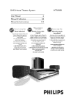
FIG. 2 shoWs a more detailed block diagram of the
timing features such as the information required to display
decoder/controller of FIG. 1 in accordance With the pre
time of day information on display 68. Apaging transmitter
ferred embodiment of the invention.
80 under the control of controller 56 transmits messages and
user requests. A conventional antenna sWitch 82 selectively
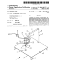
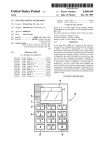
FIG. 3 shoWs an electronic device in accordance With the
couples the transmitter 80 or receiver 54 to antenna 52.
preferred embodiment.
The controller/decoder 56 of FIG. 1 can be constructed
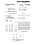
FIG. 4 shoWs one embodiment of the GUI in accordance
utiliZing a microcomputer as shoWn in FIG. 2, although
With the invention.
FIG. 5 shoWs a secondary embodiment of the GUI in 45 other hardWare arrangements as knoWn in the art can also be
used. FIG. 2 is an electrical block diagram of a microcom
accordance With the invention.
puter based decoder/controller suitable for use in the selec
accordance With the preferred embodiment of the present
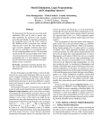
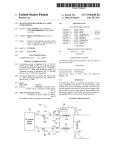
FIG. 6 highlights the operation of the animation and draW
buffers in accordance With the preferred embodiment of the
invention.
FIG. 7 shoWs a ?oWchart highlighting the basic opera
tional steps in accordance With the preferred embodiment of
the invention.
DESCRIPTION OF THE PREFERRED
EMBODIMENT
tive call receiver of FIG. 1. As shoWn, the microcomputer 56
can preferably comprise a MC68HC05 or MC68HC11 or
other similar microcomputer manufactured by Motorola,
Inc. Which preferably includes an on-board display driver
114. The microcomputer 56 includes an oscillator 100 Which
55
Referring noW to the draWings and in particular to FIG. 1,
an electrical block diagram of a electronic device such as a
selective call transceiver (e.g., a tWo-Way pager, etc.) in
accordance With the preferred embodiment of the present
(random access memory) 104 is utiliZed to store variables
derived during processing, as Well as to provide storage of
message information Which are received during operation as
invention is shoWn. The selective call transceiver 50 com
prises an antenna 52 for intercepting transmitted radio
frequency
signals Which are coupled to the input of a
receiver section 54. The R.F. signals are preferably selective
call (paging) message signals Which provide a receiver
generates the timing signals utiliZed in the operation of the
microcomputer 56. A crystal, or crystal oscillator (not
shoWn) is coupled to the inputs of the oscillator 100 to
provide a reference signal for establishing the microcom
puter timing. A timer/counter 102 couples to the oscillator
100 and provides programmable timing functions Which are
utiliZed in controlling the operation of the receiver. A RAM
a selective call receiver as previously discussed. A ROM
(read only memory) 106 stores the subroutines Which con
65
trol the operation of the receiver as Well as the routines
address and an associated message, such as numeric or
required to perform the present invention. Although the
alphanumeric message. HoWever, it Will be appreciated that
RAM 104 and ROM 106 have been shoWn internal to the
5,940,076
3
4
controller 56, these memory types can also include external
memory devices coupled to the controller 56.
or counterclockwise in groups of three. Although other
designs can accommodate the introduction of a different
number of feature/options (applications) Which are rotated
It Will be appreciated that in many microcomputer
onto the display into the user selectable ?elds.
implementations, the programmable-ROM (PROM)
memory area can be provided by, or further include, an
The Wheel concept of the present invention gives the user
EEPROM (electrically erasable programmable read only
memory). The oscillator 100, timer/counter 102, RAM 104,
a reference Which is immediately familiar, a section of a
Wheel 420. By adding more options/features the Wheel 420
simply gets bigger. Yet the user interface still presents the
and ROM 106 couple through an address/data/control bus
108 to a central processing unit (CPU) 110 Which performs
the instructions and controls the operations of the micro
computer 56.
The demodulated data generated by the receiver. is
coupled into the microcomputer 56 through an input/output
(I/O) port 112A. The demodulated data is processed by the
CPU 110, and When the received address information is the
same as the code-plug memory Which couples into the
user a predetermined number of choices, in this embodiment
three (number of displayed ?elds can be changed based on
the design) and the user is not confused or frustrated by more
choices being added/deleted.
The button locations or user selectable ?elds 422—426 are
15
placed in a radial orientation With respect to each other on
display 68. The three vieWable user selectable ?elds
422—426 are presented on the display screen 68 in an arc
microcomputer through an I/O port 112B, the message, if
arrangement. Arced line 428 Which interconnects the user
any, is received and stored in RAM 104. Recovery of the
stored message, and selection of the predetermined destina
selectable ?elds (buttons) 422—426 gives the further impres
tion address, is provided by the sWitches Which are coupled
sion to the device user that the user selectable ?elds 422—426
are part of a circle or Wheel full of features/options 402—416.
to the I/O port 112A.
The display 68 in the preferred embodiment shoWs an extra
In one embodiment of the invention, at the time a message
is received, an alert signal is generated Which can be routed
through the data bus 108 to an alert tone generator 116 that
generates the alert signal Which is coupled to the audible
alert device 58 that Was described above. Alternatively,
When the vibrator alert is selected as described above, the
microcomputer generates an alert enable signal Which is
coupled through data bus 108 to the I/O port 112B to enable
generation of a vibratory, or silent alert.
The battery saver operation of pager 50 is controlled by
the CPU 110 With battery saving signals Which are directed
over the data bus 108 to the I/O port 112A Which couples to
the poWer sWitch. PoWer is periodically supplied to the
receiver to enable decoding of the received selective call
receiver address signals and any message information Which
is directed to the receiver. substitutions and equivalents Will
occur to those skilled in the art Without departing from the
spirit and scope of the present invention as de?ned by the
25
arced line 430 having arroWs pointing in opposite directions
Which further highlights the rotational GUI. It is Worth
noting that in the preferred embodiment there is one more
option/feature Which is not shoWn in FIG. 4 and is labeled
“Available” meaning that it is not presently programmed to
accomplish a task.
AWheel having more application choices is shoWn in FIG.
5. In this embodiment, the number of offscreen application
choices 508—524 are more numerous than the offscreen
choices 408—416 found in the example shoWn in FIG. 4.
HoWever, like in the example shoWn in FIG. 4, the GUI
remains the same, presenting just three displayed (or another
35
number) choices on display 68, in this case features/options
502—506.
In the present invention the Wheel is also “spun” to add
further to the user’s frame of reference. When the user
activates user control 302 either up or doWn to reach off
screen applications (e.g., 408—416), the three neW applica
appended claims.
tions Which are brought onto display 68 are rotated quickly
Referring noW to FIG. 3, a top vieW of the tWo Way pager
is shoWn. In the preferred embodiment the tWo Way pager 50
clockWise in the case the up arroW Was depressed or coun
through the user selectable ?elds (e.g., 422—426) either
terclockWise in the case the doWn arroW Was depressed. This
invention can be used With any electronic device Which 45 quick rotation through the user selectable ?elds 422—426
creates the effect that a Wheel is being spun, making the GUI
requires or could use a graphical user interface as Will be
comprises a PAGEWRITERTM 2000, although the present
easy to understand for the user. If the neW choices Were
explained beloW. Operational control of the device is con
trolled by a keypad Which includes a plurality of user
simply draWn on the screen instead of rotated onto the
screen, the user Would have less of a point of reference for
Where the choices came from and hoW to navigate to the next
set of choices. The animation process as Well be explained
controls including user control 302 Which alloWs a user to
move Within different ?elds (user selectable) or button
locations Which are displayed on display 68. User control
302 provides the user directional control (up, doWn, right,
left) of Which ?eld (button) is currently highlighted on
display 68. The operation of tWo Way pager 50 is discussed
in detail in the PAGEWRITERTM 2000 User’s manual Which
55
beloW is thus an important addition to the Wheel concept
mentioned above.
The discussion of the present invention’s animation and
draW buffers is illustrated in FIG. 6. In the present invention,
is hereby incorporated by reference.
given the pager’s limited CPU and memory capabilities
In FIG. 4, one embodiment of the present invention’s
“Wheel” GUI is shoWn. A plurality of available features/
Which can be used for the GUI, all screen updates are draWn
directly into the user-visible screen buffer in order to save
options (applications) 402—416 are rotated through the dis
poWer and memory. In the preferred embodiment, the screen
buffer update and the animation are coordinated to yield the
illusion of the neW option ?elds rotating into place While
play 68 into user selectable ?elds or buttons 422, 424 and
426, in this particular example in groups of three. The
402—416 are rotated onto the screen onto the user selectable
they are in fact simply draWn in place.
In the preferred embodiment, tWo processes are running
simultaneously in a multi-taksing environment under the
control of controller 56. The main process alWays draWs into
a “DraW Buffer” Which is usually and in the preferred
?elds or buttons locations 422, 424 and 426 either clockWise
embodiment is the user-visible screen buffer. When render
currently displayed features/options are 402—406. Using
user control 302, a user can navigate to the other choices
(offscreen options) 408—416 available to him/her. In accor
dance With the invention, the selectable features/options
65
5,940,076
5
6
ing a scene, the user sees all of the intermediate erasures and
draWs Which make up the neW scene. But as a result of the
invention, the user sees the neW scene evolve smoothly, as
Which is illustrated as screen 610. This copy becomes the
?rst scene of the animation. At this point the display driver
is sWitched aWay from the draW buffer to present the
rendered by the parallel animation process. This gives the
contents of the animation buffer to the user in vieW 610. The
illusion to the user that the portion of the Wheel 420 Which
is visible to the user on display 68 is spinning to get some
bene?ts of copying the entire draW buffer is that it preserves
all information on the screen such as time, date and mes
saging status (e.g., in range, unread message, etc.).
of the “off screen” option/feature ?elds onto the display (in
the case of FIG. 4, off-screen options/features 408—416).
The present invention’s animation buffer performs its
tasks Without the main process having to be burdened With
any interaction With the animation. As the main process
draWs into the screen buffer, the animation task steals the
rendered data from the main screen and incorporates it into
10
The animation process 620 then erases the three buttons
that Were copied into the animation buffer. The animation
process then generates three pointers to the three buttons in
the draW buffer shoWn in vieW 602 and re-draWs the three
buttons in the neXt positions in the animation (e.g., slightly
upWard as shoWn in vieW 612. At the same time the
animation process is re-draWing the buttons, the main pro
the animation. Thus When the animation has run to
cess is updating the buttons in the draW buffer to the neW
completion, the neW data from the screen buffer Will be 15 choices starting by re-draWing the “Customize” button ?rst
displayed on the animation screen. In fact, the last scene of
604. While the re-draW of the top button occurs in vieW 604,
the animation is simply a sWitch back to the display buffer.
The animation and draW buffers are preferably memory
sections Within RAM 104.
The only coordination betWeen the tWo processes is the
forking of the animation process by the main process. Once
the animation has been launched, the main task simply runs
as alWays. Another advantage to this mechanism is that if the
the animation process again copies the three buttons from
the draW buffer to the animation buffer but since the top
button has been re-draWn, the change is re?ected in the
animation buffer as a neW choice being rotated “onto” the
screen in vieW 614.
The animation process, to create the vieW of 614 Will ?rst
animation cannot run for any reason (e.g., loW memory,
high-priority tasks taking over, etc.) the entire process can be
ignored and the main buffer simply gets re-draWn With no
25
copy from pointer 628 to display the bottom button, then
from pointer 626 to display the middle button, then from
624, to display the top button. This scene is then presented
to the user as a rotation of the “Customize” application onto
loss of system integrity.
the screen, While the “Read” application has rotated off the
In order to better understand the invention, the process of
moving from one set of available options or applications
screen. The animation process and the main process then
Which are currently displayed on display 68 to a neW set of
available options/features (applications) Which are currently
off-screen Will be discussed in accordance With the preferred
embodiment. It is Worth noting that in order to enhance the
Wheel’s rotation feature, in the preferred embodiment, neW
features/options are introduced on screen in groups of three
into the user selectable ?elds or buttons 422—426 Which are
35
located along an arc When displayed and offset to each other.
For eXample in FIG. 4, a ?rst subset of applications 402—406
are currently displayed Within user de?nable ?elds 422—426.
continue in parallel and When the main process re-draWs the
second button (“Write” button to “Set Time”) as in vieW 606,
the animation process copies the buttons to 632, 634 and
636. Note that the middle button on vieW 606 is actually
draWn in tWo locations: the partially draWn button at the
bottom of vieW 616 and the partially draWn top button
shoWn by line 630. This is because the draW buffer has
destroyed the “Write” application button With the “Set
Time” button before the animation process rotated it off
screen. This partial button enhances the “moving Wheel”
effect.
If the user control 302 is activated, a second subset of
As copying continues, the main process eventually draWs
applications either 416—412 or 408—412 Would be displayed
the third button shoWn in vieW 608 (the last neW option
“Partner” in the bottom user selectable location) in the draW
buffer and the animation process copies the three buttons in
the order of 638, 640, 660 Which shoWs the three choices
almost in their ?nal positions in vieW 618. To complete the
depending if the up or doWn arroW Were depressed.
The process starts With display screen 602 Which shoWs
the presentation of the three presently available applications
(Read 402, Write 404 and Addresses 406) available to the
45
user Which are displayed Within the user selectable ?elds
422—428. If the user Wants to select amongst one of the
animation sequence, the ?nal scene is the draW buffer itself
Which is displayed as the animation process terminates and
presently displayed applications, he simply presses the
changes the display driver to display the draW buffer 608.
up/doWn arroWs on user control 302 until the desired appli
cation is highlighted, then the user can select the application
by depressing another user control. If the user hoWever does
back from screen 618 to display buffer screen 608. The
animation screens 610—618 are displayed in a smooth and
not Want to activate any of these three presently displayed
applications, the user by pressing the doWn arroW (or up
arroW in another example), Will be able to navigate to the
neXt available set of application (option) ?elds Which are
quick fashion such that the user When vieWing display 68
perceives that the Wheel 420 is spinning.
The basic algorithm Which Was graphically illustrated in
FIG. 6, is shoWn in simpli?ed ?oWchart form in FIG. 7.
The last screen of the “Wheel spin” animation is this sWitch
55
currently off-screen. If the currently highlighted ?eld is ?eld
Upon the device user selecting a feature/option Which is not
422 pressing the up arroW Will cause the animation process
currently being displayed on the display screen 68, the draW
buffer information is copied into the animation buffer in step
to commence. If the currently highlighted ?eld is ?eld 426,
pressing the doWn arroW Will cause the animation process to
commence. Upon the user activating the user control 302
one or more times, the “Wheel spin” animation process is
begun as shoWn by arroW 620.
Once the animation process is commenced, the informa
tion on the draW buffer is copied to the animation buffer in
step 622. As such, the animation buffer Will have stored in
it the same information that Was on display screen 602,
702 (step 622 in FIG. 6). In step 704, the routine points into
the draW buffer for neW information. The display screen 68
is animated in step 706 in order to create the Wheel spinning
65
action. Finally, in step 708, the animation process is termi
nated and the draW buffer information is displayed shoWing
the neW option/feature (application) selections.
The present invention Works Well in small devices such as
pagers, etc. since it only takes a pointer if the routine is
5,940,076
7
8
implemented in the “C” programming language to keep
5. A method as de?ned in claim 1, Wherein each appli
cation Which is displayed includes an icon.
track of the draW status in the draW buffer. When a user
Wants a feature/option Which is currently not showing on the
6. A graphical user interface for an electronic device
having a display, comprising:
display, the main process signals the dormant animation
process to begin. Then the main process continues to draW 5
the neXt three buttons Without any regard to animation
eXcept that it draWs the neW buttons bottom-to-top on a spin
up of the Wheel 420 and top-to-bottom on a spin doWn so the
buttons appear in the animation buffer in proper sequence.
The present invention draWs straight into the on-screen 10
buffer to reduce RAM usage and uses no inter-process
a plurality of user selectable buttons presented on the
display, the plurality of user selectable buttons being
located on the display along an arc;
a set of available applications, each of the set of available
applications having associated graphics, Wherein a sub
set of applications is selected from the set of available
communications to help reduce the processing requirements
of the device.
If the animation designer can completely hide the
progress of the draW buffer Within the “blur” of the anima
tion and the overall effect presented to the user is a smooth
animation that starts With the currently vieWed draW buffer
a user control;
applications and displayed With their associated graph
15
ics Within the plurality of user selectable buttons pre
sented on the display; and
a controller, in response to activation of the user control,
causes the display to enter an animation mode When an
application is selected that is not currently being
screen, smoothly transitions through all of the incremental
changes during the draW buffer update, and ends With the
neXt vieW of the draW buffer. To the system designer, the
displayed, in Which the plurality of user selectable
buttons presented on the display are caused to change
their applications and associated graphics so as to make
it appear that neW applications and their associated
present invention saves poWer over standard double
buffering animation and also saves on memory and process
graphics are rotating through the plurality of user
ing overhead.
What is claimed is:
1. Amethod for providing a graphical user interface to an 25
electronic device having a display, comprising the steps of:
presenting a plurality of user selectable ?elds located
selectable buttons along the arc.
7. Agraphical user interface as de?ned in claim 6, Wherein
the applications and their associated graphics are scrolled
through the plurality of user selectable buttons in either a
clockWise or counterclockwise direction.
alone an arc on the display, each of the plurality of user
selectable ?elds highlighting an application of the
8. Agraphical user interface as de?ned in claim 6, Wherein
the plurality of user selectable buttons does not change
electronic device, Wherein the applications being dis
location Within the display.
played represent a subset of a set of available applica
9. Agraphical user interface as de?ned in claim 7, Wherein
tions;
the applications and their associated graphics are presented
selecting an application from the set of available appli
cations;
35
determining that the application Which has been selected
is currently not being displayed in the plurality of user
selectable ?elds;
comprising a memory for storing the set of available appli
cations and their associated graphics, said controller access
ing the associated graphics and displaying them in the
commencing an animation process in Which neW appli
plurality of user selectable buttons in a sequential and
cations currently not being displayed are selected from
the set of available applications, rotated into the plu
predetermined order.
11. An electronic device including a display, has a set of
available applications from Which the user of the electronic
rality of user selectable ?elds alone the arc, and dis
played;
device can choose, Wherein a subset of the set of available
stopping the animation process; and
presenting the plurality of user selectable ?elds on the
45
display each highlighting the neW applications of the
electronic device Which Were not previously shoWn on
able ?elds Which are presented along an arc on the display,
a user control;
a controller coupled to the user control;
a memory coupled to the controller, the memory contain
ing a draW buffer and an animation buffer; and
the controller presents a ?rst subset of the set of available
2. A method as de?ned in claim 1, Wherein in commenc
ing the animation process step the neW applications are
rotated along the arc through the plurality of user selectable
?elds at a rate Which causes a rotational effect When the
applications Within the plurality of user selectable
display is being vieWed by a user.
3. A method as de?ned in claim 1, Wherein the step of
55
?elds, and the controller in response to an activation of
the user control to select an application Which is not
currently being displayed, rotates through the plurality
of user selectable ?elds along the arc a second subset of
rotating into each of the plurality of user selectable
?elds a neW application that is currently not being
displayed;
(b) removing for each neW application introduced in step
(a) one of the previously highlighted applications; and
(c) repeating steps (a) and (b) until all of the plurality of
user selectable ?elds highlight neW applications.
4. Amethod as de?ned in claim 3, Wherein the animation
process is stopped When all of the plurality of user selectable
?elds is updated With a neW application.
applications is presented on the display Within user select
the electronic device, comprising:
the display.
commencing the animation process comprises:
(a) updating the plurality of user selectable ?elds by
to the plurality of user selectable buttons in a prede?ned
order.
10. Agraphical user interface as de?ned in claim 6, further
65
the set of available applications until the entire second
subset of the set of available applications is displayed
in the plurality of user selectable ?elds.
12. The electronic device de?ned in claim 11, Wherein the
controller draWs into the draW buffer the ?rst subset of the
set of available applications into the plurality of user select
able ?elds and the contents of the draW buffer are displayed
on the display.
13. The electronic device de?ned in claim 12, Wherein in
response to an activation of the user control, the controller
5,940,076
9
10
causes the contents of the draw buffer to be copied onto the
animation buffer.
18. The method de?ned in claim 17, wherein the ?rst and
second applications are rotated clockwise along the arc.
19. The method de?ned in claim 17, wherein the ?rst and
second applications are rotated counterclockwise along the
14. The electronic device de?ned in claim 13, wherein
further in response to the activation of the user control, the
controller causes the draw buffer to be updated with the
second subset of the set of available applications, and as
arc.
20. A method of providing a graphical user interface for
each of the available applications from the second subset is
being loaded into the draw buffer they are rotated into the
animation buffer which upon receiving each of the available
applications deletes one of the applications from the ?rst
subset of the set of available applications, the contents of the
animation buffer are presented on the display.
15. The electronic device de?ned in claim 14, wherein
an electronic device, comprising the steps of:
displaying at least ?rst, second and third user selectable
?elds which are presented along an arc in a display;
presenting a ?rst subset of applications selected from a set
of available applications, one each to each of the ?rst,
second and third user selectable ?elds; and
once all of the applications from the second subset are
rotated onto the animation buffer, the contents of the ani 15
rnation buffer are no longer presented on the display, instead,
the contents of the draw buffer are caused to be displayed.
16. The electronic device as de?ned in claim 14, wherein
the animation and draw buffers are eXecuted using different
processes that are running simultaneously in a rnultitasking
environrnent under control of the controller.
17. Arnethod for displaying at least ?rst, second and third
application is selected which is not currently being
user selectable ?elds which are presented along an arc in a
display, the method comprising the steps of:
presenting ?rst, second and third applications which rep
causing a second subset of applications selected from the
set of available applications to be displayed one each at
each of the ?rst, second and third user selectable ?elds
by rotating out of the ?rst, second and third user
selectable ?elds the ?rst subset of applications and
rotating in the second subset of applications when an
25
displayed within the ?rst second and third user select
able ?elds.
21. The rnethod de?ned in claim 20, wherein the second
subset of applications are rotated alone the arc into the ?rst,
resent a subset of a set of available applications, one
second and third user selectable ?elds in a clockwise fash
each displayed within the ?rst, second and third user
ion.
selectable ?elds; and
22. The method de?ned in claim 20, wherein the second
subset of applications are rotated alone the arc into the ?rst,
causing a fourth application selected from the set of
available applications, to be displayed by causing the
third application to no longer be displayed and rotating
the ?rst and second applications along the arc within
the ?rst, second and third user selectable ?elds.
second and third user selectable ?elds in a counterclockwise
fashion.