1
US006104512A
Ulllted States Patent [19]
[11] Patent Number:
Batey, Jr. et al.
[45]
[54]
[75]
6,104,512
Date of Patent:
METHOD FOR ADJUSTING THE POWER
Aug. 15, 2000
FOREIGN PATENT DOCUMENTS
LEVEL OF AN INFRARED SIGNAL
6369229
3/1988
Japan '
Inventors: Charles E. Batey, Jr.; Carlos M.
5453055
6/1993
Japan '
Rodriguez; John B. Van Zile, all of
Lake Worth, Fla.
OTHER PUBLICATIONS
PageWriterTM 2000 User’s Manual by Motorola, Inc., Docu
Inent N0. 6880496G51—O, 1997.
Williams, Millar, The IrDA Platform, Networks and Com
munications Laboratory, HP Laboratories Bristol,
[73] Assignee: Motorola, Inc., Schaumburg, Ill.
[21] Appl_ No: 09/012,444
_
HPL—95—29, Mar. 1994, HeWlett Packard @ 1995.
[22] F1199?
Jan- 23, 1998
Infrared IrDA® Complaint Transceiver, Preliminary Tech
[51]
Int C17
[52]
US. Cl. .................. .. 359/152 359/172 340/825.72
[58]
.
' ’
Field of Search ................................... .. 359/143, 110,
.
.
H04B 10/00
................................... ..............
’
nical Data pp. 57—62, HSDL—1001, HeWlett Packard.
'
IrDA® Dam Link Desi n Guide, A
455/3’8 3_ 455/522’
HeWlett Packard 1995.
endix and
PP
' 1_82,
PP
Motorola MC68328 (DragonBall)TM Integrated Processor
,
359/152_153, 157, 171_172; 455/383,
User s Manual, pp. 8—1 thru 8—13, 1995.
69> 522; 340/825~72
[56]
g
Primary Examiner—Kinfe-Michael Negash
References Cited
[57]
U.S. PATENT DOCUMENTS
ABSTRACT
An electronic device (50) includes an infrared transceiver
4 516 221
5/1985 Nakata
364/900
4’580’262
4/1986 Naylor
476497385
3/1987 Aires et a1. 1.1.......................:::"379/57
nications With a Secondary device (420 and/0r 430) at a ?rst
4:727:600 2/1988 Avakian ................................ .. 455/601
4,777,653 10/1988 Bonnerot er a1
455/69
POWer level, if the Communication hhkis not established, the
electronic device (50) increases the IR poWer level and tries
""""""""""""""" "
(510) having adjustable infrared signal intensity capability.
371/5
The electronic device (50) commences to establish commu
4,804,955
2/1989 YoshiZaWa ...... ..
340/825.44
again to establish communications. In an alternate
4,825,193
4,825,200
4/1989 SiWiak et a1. .
340/311-1
4/1989 Evans et al. ............................ .. 341/23
embodiment, the electronic device (50) includes a poWer
level table Which keeps the power level Which has been
4,939,731
7/1990 Reeget a1. .............................. .. 371/532
griseglr?oto
5’075’792
12/1991 Brown egt
5’O87’982
2/1992 smothers
''''
Kojima _ _ _ _ _ _ _ _ _ _
communicating With each of the secondary devices deter
359/137
mines the proper poWer level to use depending on the
_ _ _ __ 371/55
secondary device (420, 430) it Wants to communicate With.
5j128:942
7/1992
7/1992 Henriksson
5,218,466
6/1993 Brooks .... ..
5,220,678
6/1993
Feei . . . . . . .
- - - - -- 455/69
572477380
9/ 1993 Lee et a1~
359/118
____ __ 375/58
In still a further embodiment, instead of determining the
359/152
poWer level to use at the start of the communications, an
ongoing exchange
of signal quality information is sent
betWeen the communicating devices in order to adjust the
210151
poWer level of the devices during the communication ses
525461411 8/1996 Leiistch e161:
37/1/55
5,566,022
359/172
5,623,355
using the
method described above. The electronic device (50) before
' ' ' " 359/15'2
5,128,965
2
established for each Secondary device
175/?
10/1996 Segev ...... ..
Sion'
4/1997 Olsen .................................... .. 359/110
52
30 Claims, 11 Drawing Sheets
80
82 \
ll
68
I DISPLAY I
TX/RX
g)
ll
SWITCH
+
54
f56
r
RECEIVER
+
f 58
_
>
AUDIBLE
ALERT
DECODER/
70
CONTROLLER
f
POWER :
f
60
_ TACTILE
' ALERT
SWITCH
[74
A ll 11 ll 1
REAL T'ME
CLOCK
SWITCHES
1 W84
INFRARED
TRANSCEIVER
\
V K64
CODE
PLUG
fee .2
BATTERY
U.S. Patent
Aug. 15,2000
52
Sheet 1 0f 11
K80
<>
r68
TRANSMITTER
a2\ ‘
6,104,512
DISPLAY
5_0
Tx/Rx
SWITCH
+ r54
RECEIVER
+
56
r
K
58
AUDIBLE
—>
I
ALERT
DECODER/
70
/
CONTROLLER
60
f
TACTILE
POWER <_
_>
ALERT
SWITCH
r74
{
REAL T|ME
CLOCK
+
f
INFRARED
FI6' 1 TRANSCEIVER
84
f
SWITCHES
64
f
BATTERY
CODE
PLUG
86 \62
B++
FROM IR
118
EEfVNESFi “’
-/ 110
CENTRAL 114
I
uART
\ PROCESSING \\ DISPLAY
T0 IR
UNIT
>
T0
DRIVER
D|SpLAy
TRANS-4
cEIvER
r 108
112A
1128
\_
102
FROM
104
RCvR
To
J
RAM
COUNTER
POWER ADJUST
4
POWER
>
I/O 100
SWITCH
TO IR
>
\
OSCILLATOR
106
‘
I
RoM
“ma/IE5»
"0
<—_
I
REAL
TIME
CLOCK
AREIRT
_+
I
l
CRYSTAL
FROM CODE
MEMORY
TO vIBRATOR
f 116
FROM
T0
TRANSMITTER
> DRIVER
GENERATOR
is
>
TRANSSUCER
DRIVER
FIG. 2
U.S. Patent
Aug. 15,2000
TH
WWW
302
““*00
"IH I.
Sheet 2 0f 11
6,104,512
U.S. Patent
Aug. 15,2000
f
Sheet 3 0f 11
420
PRINTER
4/
SECONDARY
DEVICE #2
FIG. 4
6,104,512
U.S. Patent
Aug. 15,2000
Sheet 4 0f 11
6,104,512
imom
20>mQ wm EMJOPZmo Sm gf
[IM
| vcIfm
2m
mum
9h
2m5m?
Q|L |
Va8NEE0J
9?Q,_/EISE
0wmw>m
EN
.\<09:A“.
>in- QfCJB0E 5
m8
gm.u?“
U.S. Patent
Aug. 15,2000
Sheet 5 0f 11
6,104,512
REG 3v
f
602
D/A
606
R
CONVERTER
/
\
604
TO
LEDA
K606
/ 702
SET POWER TO
LOWEST LEVEL
+
f 704
OPEN AN IR
4
CONNECTION
706
CONNECTION
SUCCESFULLY
OPERATED ?
/ 710
|NCREMENT
POWER LEVEL
712
POWER
LEVEL 5
MAX ?
YES
r 714
7
K08
CONNECTION
CONNECTION
ESTABLISHED
FAILED
FIG. 7
U.S. Patent
Aug. 15,2000
Sheet 6 0f 11
6,104,512
/ 802
SET POWER TO LEVEL =
MIN.
I
r 8”4
EXECUTE DISCOVERY
SEQUENCE FOR ALL
SLOTS
4
K808
DID ANY
SECONDARY DEVICES
RESPOND ‘.7
INCREMENT
POWER LEVEL
YES
K812
FOR EACH NEW
SECONDARY, IF
THERE IS NO ENTRY
IN TABLE FOR THE
SECONDARY,
RECORD THE POWER
LEVEL IN TABLE
f816
CONNECTION
FAILED
814
NO
ANY
SECONDARIES
IN TABLE
YES
818
/
CONTINUE WITH
CONNECTION
SEQUENCE
FIG. 8
U.S. Patent
Aug. 15,2000
Sheet 7 0f 11
r 902
PARAMETER
NEGOTIATION
904
RECEIVE
POWER PACKET
WITHIN
TIMEOUT ?
YES
SEND ACK
YES
MORE
SECONDARIES
/- 906
6,104,512
U . S . Patent
Aug. 1 5, 2000
s heet s 0 r11
6,104,512
r1002
PARAMETER
NEGOTIATION
+
/1004
SET POWER LEVEL
=M|N
+
[1006
SEND POWER
4
PACKET
r
1010
INCREMENT
REAiEILVE
POWER
LEvEL
7
YES
f- 111 6
SAVE POWER LEVEL
1118
FIG. 10
1112
POWER
LEVELg
MAX?
1114
U.S. Patent
Aug. 15,2000
Sheet 9 0f 11
6,104,512
f- 1 102
PARAMETER
NEGOTIATION
1104
RECEIVE
DISTANCE REQUEST
PACKET WITHIN
TIMEOUT ?
r1106
SEND DISTANCE
PACKET
1108
RECEIVE
POWER
PACKET WITHIN
TIME-OUT
[-1110
SEND ACK
1112
YES
MORE
SECONDARIES
FIG. 11
U.S. Patent
Aug. 15,2000
6,104,512
Sheet 10 0f 11
f- 122
0
PARAMETER
NEGOTIATION
+
f 1204
SEND DISTANCE
REQUEST PACKET
(POWER LEVEL : MAX)
1208
RECEIVE
DISTANCE PACKET
WITHIN
TIMEOUT ?
. YES
K1210
TRNSFORM DISTANCE
TO POWER LEVEL P
I
K1212
SET POWER LEVEL = P
+
[1214
SEND POWER PACKET
<
/. 1218
INCREMENT
POWER
LEVEL
RECEIVE
ACK
?
YES
r
1220
POWER
LEVEL 5
MAX ?
1222
1224
SAVE POWER LEVEL
1226
FIG. 12
U.S. Patent
Aug. 15,2000
Sheet 11 0f 11
6,104,512
f 1 302
WAITING FOR FRAME
1304
NO
RECEIVE
FRAME WITHIN
TIMEOUT
?
1306
BER >
NO
THRESHOLD OR
ANY NAK’ d
FRAMES
'?
f- 1308
-—>
f- 1314
DEBOUNCE ++
DEBOUNCE -
1316
DEBOUNCE >
DEBOUNCE <
THRESHOLD
7
-THRESHOLD
?
YES
r 13 1 8
{-1312
INCREMENT POWER
DECREMENT POWER
LEVEL
LEVEL
DEBOUNCE = O
DEBOUNCE = O
1320
FIG. 13
6,104,512
1
2
METHOD FOR ADJUSTING THE POWER
LEVEL OF AN INFRARED SIGNAL
BRIEF DESCRIPTION OF THE DRAWINGS
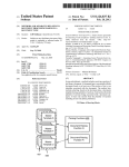
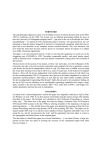
FIG. 1 is a block diagram of an electronic device in
accordance With the preferred embodiment of the present
FIELD OF THE INVENTION
invention.
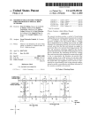
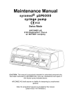
FIG. 2 shoWs a more detailed block diagram of the
decoder/controller of FIG. 1 in accordance With the pre
ferred embodiment of the invention.
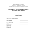
FIG. 3 shoWs an electronic device in accordance With the
This invention relates in general to electronic devices, and
more speci?cally to a method for adjusting the poWer level
of an infrared signal.
BACKGROUND OF THE INVENTION
Some electronic devices use built-in infrared (IR) cir
cuitry in order to alloW them to communicate With other
10
preferred embodiment of the invention.
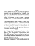
FIG. 4 shoWs a system in accordance With the invention
Which includes an electronic device and other devices Which
devices either on a unidirectional or bi-directional basis. For
can communicate With each other using IR communications.
example, some calculators have built-in infrared circuits
FIG. 5 shoWs a schematic of an adjustable IR transceiver
Which alloW them to communicate With printers. While
15 circuit in accordance With the invention.
some computer keyboards use built-in infrared links to
FIG. 6 shoWs an alternative adjustable current circuit
communicate With their respective computer system.
Which can be used With the IR transceiver shoWn in FIG. 5.
Infrared links are cost effective solutions and are espe
FIG. 7 is a ?oWchart highlighting the steps taken to adjust
cially suited for portable electronic devices given that they
the IR poWer level in accordance With one embodiment of
are fairly simply to implement, do not take up much room
on the electronic device’s main printed circuit board (PCB)
and are fairly inexpensive to design-in.
Infrared communication links hoWever present several
draWbacks over other types of communication links, such as
RS-232 serial links, etc. One draWback to IR communica
tions is that if the tWo devices Which are communicating
the present invention.
FIG. 8 is a ?oWchart highlighting the steps taken to adjust
the IR poWer level in accordance With a second embodiment
25
of the present invention.
FIG. 9 is a ?oWchart highlighting the steps taken by a
primary device to adjust the IR poWer level in accordance
With a further embodiment of the present invention.
FIG. 10 is a ?oWchart highlighting the steps taken by a
With each other are placed in very close physical proximity
to each other, IR distortion due to increased bit error rate
may affect the communications if the IR transmitter(s) are
operating at high IR poWer (intensity) levels. This problem
typically comes about because the IR transceivers in the
electronic devices may be set at a certain poWer level in
order to guarantee IR communications at up to a certain
distance (e.g., one meter) from the other device. In order to
meet the distance speci?cation, the IR transceivers are set 35
With IR transmit poWer levels Which Will guarantee com
munications at the given distance (e.g., one meter, etc.),
While still providing a high level of noise immunity in a
typical use (e.g., of?ce) environment. One standard setting
body Which sets such speci?cations for the industry is “The
secondary device to adjust the IR poWer level in accordance
With the embodiment of FIG. 9.
FIG. 11 is a ?oWchart highlighting the steps taken by a
primary device to adjust the IR poWer level is accordance
With a further embodiment of the present invention.
FIG. 12 is a ?oWchart highlighting the steps taken by a
secondary device to adjust the IR poWer level in accordance
With the embodiment of FIG. 11.
FIG. 13 is a ?oWchart highlighting the steps taken to
adjust the IR poWer level in accordance With a further
embodiment of the present invention.
DESCRIPTION OF THE PREFERRED
EMBODIMENT
Infrared Data Association” (IrDA), Which has been set up to
establish standards for infrared communications. In order to
be compliant With some of the IrDA standard(s), a IR
transmitter must typically operate at a high enough poWer
Referring noW to the draWings and in particular to FIG. 1,
an electrical block diagram of a ?rst electronic device such
level to guarantee communications up to a certain distance 45 as a selective call transceiver (e.g., a tWo-Way pager, etc.) in
(e.g., one meter) aWay from another device.
Another problem typically encountered using IR commu
nications is found When the IR transmitters (or transceivers)
accordance With the preferred embodiment of the present
invention is shoWn. The selective call transceiver
assistance (PDAs) having radio communications
(communication device) 50 comprises an antenna 52 for
intercepting transmitted RF signals Which are coupled to the
input of a receiver section 54. The RF signals are preferably
selective call (paging) message signals Which provide a
capabilities, etc. The problem in this environment is that the
embedded IR circuitry can sometimes generate noise Which
may affect the radio frequency transmissions of the device in
question. The noise generation of the IR circuitry is some
or alphanumeric message. HoWever, it Will be appreciated
that other Well knoWn paging signaling formats, such as tone
only signaling or tone and voice signaling, Would be suitable
are designed into portable radio frequency (RF) communi
cation devices such as tWo-Way pagers, personal digital
receiver address and an associated message, such as numeric
55
times Worse at higher IR transmissions levels since the
electronic device’s poWer supply is more heavily loaded at
the higher IR transmit poWer levels.
A ?nal problem typically found With the use of IR
circuitry in portable electronic devices is that in situations
for use as Well. The receiver 54 processes the RF signal and
produces at the output a data stream representative of a
demodulated address and message information. The
demodulated address and message information are coupled
into the input of a decoder/controller 56 Which processes the
Were the IR transmissions are set at high poWer levels, the
information in a manner Well knoWn in the art. A poWer
IR transceiver operation Will increase the battery charge
sWitch 70, coupled to the decoder/controller 56, is used to
control the supply of poWer to the receiver 54, thereby
providing a battery saving function as is Well knoWn in the
times for the portable electronic devices When the electronic
device is being charged, if IR communications are taking
place during the charging of the electronic device. Higher IR
levels for portable electronic devices also mean reduced
battery life for the portable devices.
65
art for use With selective call receivers.
For purposes of this illustration, it Will be assumed that
the FLEXTM (FLEXTM a trademark of Motorola, Inc.) pro
6,104,512
3
4
tocol for tWo-Way paging Which is Well known in the art is
controller 56, these memory types can also include eXternal
memory devices coupled to the controller 56.
used, although other signaling formats (e.g., POCSAG, etc.)
could be utiliZed as Well. When the address is received by
It Will be appreciated that in many microcomputer
the decoder/controller 56, the received address information
implementations, the programmable-ROM (PROM)
is compared With one or more addresses stored in a code
memory area can be provided by, or further include, an
plug (or code memory) 64, and When a match is detected, the
EEPROM (electrically erasable programmable read only
memory). The oscillator 100, timer/counter 102, RAM 104,
message is stored in memory. Optionally, an alert signal is
generated to alert a user that a selective call message, or
page, has been received. The alert signal is directed to an
audible alerting device 58 for generating an audible alert or
to a tactile alerting device 60 for generating a silent vibrating
alert. SWitches 62 alloW the user of the selective call receiver
to select betWeen the audible alert 58 and the tactile alert 60
10
in a manner Well knoWn in the art.
The message information Which is subsequently received
is stored in memory (not shoWn) and can be accessed by the
15
user for display using one or more of the sWitches 62 Which
CPU 110, and When the received address information is the
same as the code-plug memory Which couples into the
any, is received and stored in RAM 104. Recovery of the
stored message, and selection of the predetermined destina
tion address, is provided by the sWitches Which are coupled
to the I/O port 112A.
Speci?cally, by the use of appropriate functions provided by
the sWitches 62, the stored message is recovered from
memory and processed by the decoder/controller 56 for
displaying by a display 68 Which enables the user to vieW the
message. A real time clock circuit 74 provides conventional
timing features such as the information required to display
In one embodiment of the invention, at the time a message
25
80 under the control of controller 56 transmits messages and
user requests. A conventional antenna sWitch 82 selectively
couples the transmitter 80 or receiver 54 to antenna 52.
A battery 86 provides poWer to the tWo-Way pager 50.
Preferably, battery 86 is a rechargeable battery variety such
as those made using nickel-metal hydride cells, etc. Pager 50
also includes an internal infrared transceiver 84 for com
municating With eXternal devices. The internal infrared
transceiver 84 Will be discussed in more detail further beloW.
Although in the preferred embodiment an infrared trans
ceiver 84 is used, it can be appreciated that if the pager 50
does not need to have bi-directional communication With the
external devices, an infrared transmitter circuit alone could
be utiliZed in order to provide uni-directional IR transmis
sions as contemplated by some embodiments of the present
invention.
The controller/decoder 56 of FIG. 1 can be constructed
utiliZing a microcomputer as shoWn in FIG. 2, although
coupled into the microcomputer 56 through an input/output
(I/O) port 112A. The demodulated data is processed by the
microcomputer through an I/O port 112B, the message, if
provide such additional functions as reset, read, delete, etc.
time of day information on display 68. Apaging transmitter
and ROM 106 couple through an address/data/control bus
108 to a central processing unit (CPU) 110 Which performs
the instructions and controls the operations of the micro
computer 56.
The demodulated data generated by the receiver is
35
is received, an alert signal is generated Which can be routed
through the data bus 108 to an alert tone generator 116 that
generates the alert signal Which is coupled to the audible
alert device 58 that Was described above. Alternatively,
When the vibrator alert is selected as described above, the
microcomputer generates an alert enable signal Which is
coupled through data bus 108 to the I/O port 112B to enable
generation of a vibratory, or silent alert.
The battery saver operation of pager 50 is controlled by
the CPU 110 With battery saving signals Which are directed
over the data bus 108 to the I/O port 112A Which couples to
the poWer sWitch. PoWer is periodically supplied to the
receiver to enable decoding of the received selective call
receiver address signals and any message information Which
is directed to the receiver. Infrared communications to and
from the infrared transceiver circuit 84 are coupled to the
controller 56 via universal asynchronous receiver/
transceiver (UART) 118. Information from the real-time
clock 74 are also coupled to the controller via I/O port 112A.
Information to be transmitted via RF transmitter 80 are acted
other hardWare arrangements as knoWn in the art can also be
used. FIG. 2 is an electrical block diagram of a microcom 45
puter based decoder/controller suitable for use in the selec
tive call receiver of FIG. 1. As shoWn, the microcomputer 56
can preferably comprise a MC68HC05, a MC68HC11, or a
MC68328 processor manufactured by Motorola, Inc., or
other similar microcomputers or microprocessors Which
preferably include an on-board display driver 114. The
upon by the CPU 110 and sent via bus 108 to I/O port 112B.
In accordance With the present invention CPU 110 provides
the needed poWer adjustments signals to infrared transceiver
84 via I/O 112B as Well be eXplained in more detail further
beloW.
Referring noW to FIG. 3, a top vieW of the tWo Way pager
50 is shoWn. In the preferred embodiment the tWo Way pager
50 comprises an electronic device such as a PAGE
microcomputer 56 includes an oscillator 100 Which gener
WRITERTM 2000 tWo-Way pager modi?ed to include the
ates the timing signals utiliZed in the operation of the
microcomputer 56. A crystal, or crystal oscillator (not
shoWn) is coupled to the inputs of the oscillator 100 to
provide a reference signal for establishing the microcom
puter timing. A timer/counter 102 couples to the oscillator
100 and provides programmable timing functions Which are
present invention. It is Worth noting that the present inven
55
utiliZed in controlling the operation of the receiver. A RAM
(random access memory) 104 is utiliZed to store variables
derived during processing, as Well as to provide storage of
general operation (eXcept for the present invention) of a tWo
Way pager 50 is discussed in detail in the PAGEWRITERTM
2000 User’s manual Which is hereby incorporated by refer
message information Which are received during operation as
a selective call receiver as previously discussed. A ROM
(read only memory) 106 stores the subroutines Which con
trol the operation of the receiver as Well as the routines
required to perform the present invention. Although the
RAM 104 and ROM 106 have been shoWn internal to the
tion can be used With any type of electronic device Which
requires, or could use, an IR circuit as Will be explained
beloW. Operational control of the device is controlled by a
keypad Which includes a plurality of user controls Which
alloWs a user to move Within different ?elds (user selectable)
or button locations Which are displayed on display 68. The
65
ence. An IR port 302 found in the rear of pager 50 provides
a port for IR transmissions to be sent and received by pager
50.
In FIG. 4, an IR system is shoWn Which includes pager 50
and a second electronic device such as a printer (also
6,104,512
5
6
referred to as the ?rst secondary device) 420. Communica
tions between pager 50 and printer 420 is accomplished via
level is ?xed. The transmit poWer level for a given session
is determined during the discovery phase of the communi
cation session. The poWer level is adjusted by controller 56
providing the proper signal to the IR poWer adjustment
IR. Printer 420 includes an internal IR transceiver Which
communicates With the pager 50 via IR port 402. A second
secondary device 430 (alternate second electronic device)
Which can also communicate With pager 50 is also shoWn in
FIG. 4. Device 430 also includes a IR transceiver Which
alloWs it to have IR communications With pager 50.
Referring noW to FIG. 5, a detailed schematic of the IR
circuit 84 located Within the pager 50 is shoWn. The IR
circuit 84 includes a conventional IR transceiver 510 such as
an HSDL1001 IR transceiver manufactured by HeWlett
Packard, Inc. or other conventional IR transceivers manu
factured by other manufacturers. IR transceiver 510 has a
built-in IR receiver and transmitter. Data to be transmitted
circuit.
2. Packed Based PoWer Management—In this type of poWer
management, the IR poWer can vary at any time during a
particular communication session. The transmit poWer for a
given packet of information is determined by signal quality
10
edgment.
Session Based PoWer Management
15
by pager 50 is sent via signal line 508 (labeled IRDA-TXD),
the data to be transmitted is processed by controller 56 and
sent to the IR transceiver 510 via the transmit signal line
508. A chip enable signal 512 (labeled IRDAiEN) is used
to enable the IR transceiver 510.
IR signals received by the IR transceiver via IR port 302
are decoded by the IR transceiver 510 and sent to controller
56 via receive signal line 514 (labeled IRDAiRXD). In
accordance With the present invention, the IR poWer level of
the IR transmitter found in transceiver 510 is controlled by
a control signal sent via line 516 from controller 56. In
accordance With the preferred embodiment, the control
information that is passed along With the packet acknoWl
There are several different Ways to implement session
based poWer management in accordance With the invention
depending on the particular design constraints of the par
ticular design at hand. In one application of session based
poWer management, the application softWare controls the
transmit poWer level of IR transceiver 510, While the con
ventional IrDA stack softWare controls the transmit enable
line 512 for the IR transceiver 510. The idea in this appli
cation is to attempt a connection (communication link With
another device) starting at a minimum poWer level. If the
connection fails, the IR poWer level is incremented and the
device retries to set-up a communication link.
25
This method is highlighted in FIG. 7. In step 702, the IR
poWer level is set at a ?rst or loWest poWer level. In step 704,
an IR connection betWeen the pager 50 and another device
signal adjusts a digital potentiometer 504 Which controls the
(e.g., printer 420) is attempted. If in step 706, the connection
amount of base current in transistor 506. This in effect
controls the amount of current alloWed to How to IR trans
is successful, in step 708, the communication link is estab
ceiver 510, thereby adjusting the poWer level (intensity) of
hoWever in step 706 the connection is not successful, in step
the transmitted IR signals. In another embodiment, a ?xed
resistor could be used in the base of transistor 506 and the
level Which is greater than the ?rst poWer level. In step 712,
lished betWeen the tWo devices at that poWer level. If
710 the IR poWer level is incremented to a second poWer
digital potentiometer could be placed betWeen the REG3V
voltage line 502 and the transistor’s emitter terminal.
35
In FIG. 6, an alternate embodiment of the IR poWer
adjustment circuit is shoWn, Which can be used With the IR
transceiver circuit shoWn in FIG. 5. In this poWer adjustment
circuit, a digital to analog converter 602 under the control of
controller 56 is used instead of a digital potentiometer. A
?xed resistor 604 is located betWeen the D/A converter 602
and the base terminal of transistor 606. The collector ter
minal 608 is coupled to the LEDA terminal of IR transceiver
712 it is determined that the current poWer level is greater
than the maximum alloWable poWer level, the connection is
caused to fail in step 714. At Which time an audible or visual
indication can be given to the user of pager 50 to let him
knoW of the connection failure.
510. It should be noted that there are many other circuit
designs Which can be implemented by those of ordinary skill
45
in the art Which Would alloW for the adjustment of the
transmit IR poWer level of the IR transceiver 510 by
controller 56 in order to implement the IR poWer adjustment
methods of the present invention discussed beloW.
The main advantages to this session based application is
that it requires no modi?cation to the existing IrDA stack of
communication protocols Which may already be residing in
the device. This poWer adjustment method lets the electronic
device establish an IR link at the loWest required transmit IR
poWer level, thereby minimiZing current drain and noise
The IrDA family of protocol speci?cations require that the
IR transceiver support a minimum transmission distance in
order to be certi?ed as “IrDA compliant”. For example, to
support a minimum transmit distance of 1 meter, the IR
transmitter needs to be driven at a very high poWer level
relative to What current pager poWer supplies can typically
it is determined if the current poWer level is set at a level less
than or equal to a maximum poWer level Which is predeter
mined and stored in the pager 50. If the current poWer level
is found to be equal to or less than the maximum poWer level
the routine attempts a neW connection in step 704. If in step
generation in device 50. The different poWer levels the pager
50 can chose from are preferably preprogrammed into the
pager 50. The poWer level values adjust the IR poWer
adjustment circuit (shoWn in FIGS. 5 and 6) to provide
prede?ned IR output transmit intensity levels. These poWer
55
level values are preferably stored in nonvolatile memory
support. In accordance With the present invention, the poWer
to the IR transceiver 510 is dynamically adjusted in order to
such as EEPROM, etc. These poWer levels values Will cause
minimiZe as much as possible the amount of current utiliZed
converter 602, Which Will in turn cause a transmit poWer
by the electronic device in driving the IR transceiver 510.
The present invention presents several methods of adjusting
adjustment to occur With IR transceiver 510.
an adjustment to either digital potentiometer 504 or D/A
Asecond application of session based poWer management
is highlighted in FIG. 8. This method is similar to the
the poWer level of the IR transceiver 510. The invention
encompasses tWo main types of dynamic poWer manage
method discussed above, hoWever this method is imple
mented Within the IrLAP portion of the IrDA stack, Which
hides the details of poWer management from the pager’s
ment for infrared communications betWeen tWo or more
electronic devices:
1. Session Based PoWer Management—In this type of poWer
management, poWer can vary from communication session
to communication session, but for a given session, the power
65
application programs. For a better detail of IrLAP and other
components of the IrDA stack of protocols, one is referred
to an article entitled “The IrDA Platform”, by Stuart K.
6,104,512
7
8
Williams and lain Millar, dated Mar. 1994, and Which is
the maXimum predetermined poWer level threshold has been
surpassed as determined in step 810.
Once the discovery phase of the communication link
establishment has been completed, pager 50, Will use the
information in the poWer level table to adjust the IR trans
ceiver’s poWer level for each of the secondary devices the
pager 50 is communicating With in step 818. As such,
messages directed individually to each of the secondary
hereby incorporated by reference.
To open a connection, the IrLAP softWare on the primary
device, pager 50, implements the algorithm described in
FIG. 8. The main idea here is to execute the discovery
process starting at a minimum transmit poWer level. If no
secondary devices respond, the poWer level is incremented
and a retry is performed. For each device that does respond,
devices Will be transmitted at the loWest poWer level
an entry is placed in a table stored in memory that indicates
the poWer level used for that particular secondary device,
10
along With the device’s identi?cation number. This ensures
that the minimum poWer level required for each secondary
device is used by the primary device. When the primary
table for any of the stored secondary devices to guarantee
that all of the secondary devices receive the broadcast
device, in this case pager 50, Wants to communicate With any
of the secondary devices Which have responded, it ?rst
15
determines the poWer level to use for that particular sec
ondary device by reading the poWer level table stored in
message.
Referring noW to FIGS. 9 and 10, a more sophisticated
algorithm than that discussed in FIG. 8 is shoWn. This
particular method builds on the method discussed With
reference to FIG. 8 by adding an additional step Which
RAM 104 associated With that particular device’s identi?
cation number. Thus, When communicating With multiple
secondary devices, the transmit poWer level can vary for
each one. Pager 50 Will have stored for each of the secondary
devices an identi?cation number Which corresponds to that
particular secondary device and the poWer level value to be
used by pager 50 in memory.
In step 802, the poWer level is set to a predetermined
minimum level. A discovery sequence is executed for each
of the communication slots. Each slot in the communication
protocol alloWs for communication With a different second
ary device, so therefore this application alloWs for the
required to achieve communications With that particular
secondary device. In the case that pager 50 Wants to broad
cast a message to all of the secondary devices at one time,
pager 50 Will use the highest poWer level stored in the poWer
alloWs the secondary devices 420, 430 to optimiZe their
25
transmit poWer levels as Well. The primary device 50 is able
to transmit to each secondary device at its optimum poWer
level, and each secondary is able to transmit back to the
primary at its optimum poWer level. This is done in a fashion
that maintains compatibility With secondary devices that are
not poWer-enhanced. This method provides a session-based
poWer management scheme that supports both primary and
secondary devices While maintaining backWard compatibil
ity.
primary device, pager 50, to communicate With multiple
To open a connection, the IrLAP softWare on the primary
secondary devices (e.g., secondary devices 420 and 430),
device 50 implements the algorithm described in the How
each at its oWn optimum poWer level.
chart in FIG. 8 and as described above. Doing this estab
In step 806, the device determines if any of the secondary
devices responded to the discovery sequences of step 804. If
any of the secondary devices responded, the poWer level
lishes the primary device’s transmit poWer levels for each
secondary device it is connected to. The primary device than
continues With parameter negotiation in step 902 for the ?rst
secondary device. At the conclusion of parameter
35
used to achieve communications is stored in a poWer level
table stored in the pager’s memory as mentioned above. The
poWer level table Which is located in RAM 104 Will include
negotiation, the secondary device is given the opportunity to
perform its poWer management routine as described in the
?oWchart in FIG. 10. The routine for the primary device 50
is shoWn in FIG. 9, While the routine for the secondary
device(s) is shoWn in FIG. 10.
If a secondary device 420, 430 is not poWer-enhanced, the
the identi?cation number of the particular secondary device
(s) and the poWer level used to achieve the communication
link With that device(s).
In step 808, the IR transmit poWer level is incremented if
no secondary devices have responded to the communication
message transmitted by pager 50 at the minimum poWer
level set in step 802. In step 810 it is determined if the
current poWer level is above the preset maXimum poWer
level Which is stored in nonvolatile memory. If the current
poWer level has not surpassed the predetermined maXimum
poWer level Which is stored in pager 50, the process returns
to step 804. HoWever, if the poWer level has surpassed the
predetermined maXimum poWer level, the routine moves on
to step 814.
In step 814, the process determines if there is any infor
mation stored for any secondary devices in the poWer level
table. If no information is stored for any secondary device in
the poWer table, the connection process is determined to
have failed in step 816. As part of step 816, the pager 50 can
provide an audio and/or visual alert to the user indicating
primary device 50 Will time-out in step 904, and continue
45
the secondary Within the predetermined time-out WindoW,
the primary sends an acknoWledgment (ACK) message to
the secondary device in step 906. The above steps are
repeated for each of the secondary units stored in the poWer
level table stored in pager 50. Once this is ?nished in step
910, the primary device continues With the communication
session in step 910.
The secondary device 420 or 430 commences normal
parameter negotiations in step 1002. The secondary device
55
through the steps and increment the IR poWer level until all
of the secondary devices have established communication or
sets its transmit poWer level at a predetermined minimum IR
transmit poWer level in step 1004. The secondary device
than transmits a packet to the primary in step 1006.
If an acknoWledgment message is received from the
primary device in step 1008, the poWer level used (in this
that a communication link Was not able to be established
With the one or more secondary devices 420 and/or 430.
If in step 806 one or more secondary devices responded
to the communication message, the secondary device iden
ti?cation number and the poWer level used to achieve
communications With the device are recorded and stored in
the poWer level table. The routine Will continue to loop
With the neXt secondary device found in the poWer table
repeating steps 902—906. If a poWer packet is received from
case the minimum poWer level) is stored in a poWer table
stored in the secondary device’s memory similar to that
described above With reference to FIG. 8 for the primary
device in step 1116. Normal communications is then
resumed betWeen the primary and secondary devices in step
65
1118.
If no acknoWledgment is received Within a predetermined
period of time in step 1008, the secondary device increases
6,104,512
10
If in step 1216 it is determined that no acknoWledgment
has been received Within a certain period of time, the
transmit IR poWer level is incremented in step 1218. In step
1220 it is determined if the poWer level is above a certain
maximum level. If it is determined that the poWer level is
its transmit power level in step 1010. It is then determined
if the power level is less than or equal to a predetermined
maximum level in step 1112. If the maximum poWer level
has not been surpassed as determined in step 1112, the
routine loops back to step 1006 using the next higher poWer
level. If in step 1112 it is determined that the maximum
poWer level has been surpassed, the connection fails in step
1114. An alarm can be provided at the secondary device
indicating that the connection failed as part of step 1114.
Afurther enhancement to the routines of FIGS. 9 and 10
are shoWn in FIGS. 11 and 12. Assuming that the IR
transceiver 84 has fairly consistent transmit and receive
beloW the predetermined maximum level the routine loops
back to step 1214. If hoWever, the poWer level is determined
to be above the predetermined maximum poWer level, the
routine fails in step 1224.
10
characteristics, it is possible to empirically determine the
distance betWeen the primary and secondary devices based
on the transmit poWer level used to establish the commu
nication link(s). The primary and secondary devices Would
15
each have a table of average distances indexed by transmit
poWer levels. Thus, once the primary device has determined
initial poWer levels for all primary and secondary devices.
Then, as each device sends data/idle frames, they Will
contain additional signal strength information in the form of
distance information Would then be transmitted to the sec
ondary device. The secondary device Would use the distance
information to extrapolate a starting transmit poWer level.
This Would help speed up the time it takes the secondary
a bit error rate (BER) measurement or some other Well
knoWn measurements (e. g., signal-to-noise ratio, etc.) Which
device to establish the correct poWer level to establish
25
?rst frame or other frame transmitted.
Whenever a primary or secondary device transmits a
frame With the P/F bit set (indicating the last frame in a
sequence “S” has been transmitted and noW is Waiting for a
35
ondary device. In steps 1108—1114, like previously dis
(BER>threshold))
has received a poWer packet Within the time-out WindoW in
THEN increment poWer level
step 1108, it then transmits an acknowledgment signal to the
secondary in step 1110 if it received the poWer packet. In
step 1112, it is determined if other secondary devices are
communicating With the primary, and if so, parameter nego
ELSE decrement poWer level. A debounce trigger point is
built-in as a further enhancement into this algorithm in
order to ?lter out bursty errors and avoid unnecessary
poWer adjustments. Idle frames received Will also pref
erably contain BER data from the last transmission.
tiations are also commenced for those secondary devices.
The secondary device routine is shoWn in FIG. 12. In step
45
1304 it is determined if the frame has been received Within
a predetermined time-out WindoW. If the frame Was received
Within the time-out WindoW, in step 1306 it is determined if
the BER is greater than a predetermined BER threshold, or
if any NAK (no acknoWledgment) packets have been
55
device using its stored distance table information transforms
the received distance information into a particular poWer
received or no acknoWledgment (ACK) packet have been
received. If any of these are met, the routine moves on to
level (P) in step 1210. The secondary device in step 1212,
sets the poWer level of its IR transceiver to “P” (“P” being
one of the available poWer levels) and sends a poWer packet
in step 1214 at that poWer level. Like the previously dis
cussed algorithms, the secondary device in step 1216, then
determines if it has received an acknoWledgment packet
from the primary device. If so, the poWer level used is stored
in RAM in step 1222 in association With the primary
device’s identi?cation information, and the devices continue
With normal communications in step 1226.
The BER for a particular transmission sequence can be
determined using one of a number of Well knoWn BER
algorithms knoWn in the art.
Referring to FIG. 13, in step 1302, the device (either a
primary or secondary) Waits for an incoming frame. In step
transmits a distance request packet to the primary device
using the maximum poWer level stored in its memory, in
order to have the greatest chance of communicating With the
primary device. In decision step 1206, it is determined if the
secondary device has received the distance packet from the
primary device Within the time-out WindoW. If the distance
packet is not received Within the predetermined time-out
WindoW, the communication link fails in step 1208.
If the distance packet is timely received, the secondary
response), the next frame received Will contain BER data for
the frame sequence “S”. Looking at the ?oWchart shoWn in
FIG., 13, the routine implements a feedback mechanism for
poWer adjustments as folloWs:
IF ((frame Was NAKed) OR (no ACK/NAK received) OR
cussed With respect to FIG. 9, the primary determines if it
1202 the secondary device commences parameter negotia
tions With the primary device 50. In step 1204, the secondary
provide an indication as to the current conditions of the
communication link. For every frame or sequence of frames
transmitted by a device, the BER value from the most
recently received data is included Within the data area of the
mation presented to the user).
Referring to FIG. 11, the primary device commences
parameter negotiations in step 1102. In step 1104 it is
determined if a distance request packet has been received by
a particular secondary device Within a time-out WindoW. If
the distance request message has been received in step 1104,
the primary device transmits a distance packet Which
includes the extrapolated distance in step 1106 to the sec
secondary devices to dynamically adjust poWer throughout
a session. This is advantageous When the devices are not
stationary for the duration of a session. This routine is an
enhancement to the routine discussed With reference to
FIGS. 9 and 10. Those routines are used to establish the
its transmit poWer level using the routines described above,
it Would lookup the approximate distance in the table. This
communications With the primary device. This distance
information could also be used by both the primary and
secondary devices for other purposes (i.e., additional infor
Packet-based PoWer Management
Packet based poWer management is accomplished in
accordance With the invention by incorporating poWer
related information into the handshake protocol during
transmission of data and idle frames betWeen the primary 50
and secondary devices 420, 430. This alloWs the primary and
65
step 1308. In step 1308, a ?rst debounce counter (labeled as
DEBOUNCE++ in FIG. 13) Which is stored in the device is
incremented a predetermined amount. Note that the
debounce threshold is different than the BER threshold.
In step 1310, it is determined if the debounce value is
greater than a ?rst prede?ned debounce threshold level
stored in the device. If it is, then in step 1312 the poWer level
is incremented and the debounce value is set at Zero (reset).
In step 1320, the communication betWeen the tWo devices
continues With the device again Waiting for a frame to
receive or a frame to transmit.
6,104,512
11
12
If in step 1306 it is determined that the BER is less than
tronic device to establish the IR communication link
With the second electronic device.
6. A method as de?ned in claim 5, Wherein the ?rst
the prede?ned threshold, a negative acknowledgment
(NAK) has been received or no acknowledgment (ACK) has
been received , in step 1314, a negative debounce counter
electronic device uses the poWer level it stored to commu
(labeled DEBOUNCE—in FIG. 13) is decreased. In step
nicate With the second electronic device after the IR com
municate link has been established betWeen the ?rst and
second electronic devices.
7. A method as de?ned in claim 1, Wherein the second
electronic device after the ?rst electronic device has estab
lished a communication link With the second electronic
1316, it is then determined if the debounce value is less than
a negative or second threshold level (labeled as
“—THRESHOLD” in FIG. 13) also stored in the device. If
the debounce value is loWer than the threshold, in step 1318,
the IR transmit poWer level is decremented and the
device performs the folloWing steps in order to determine
debounce value is set reset. The routine then moves on to
the proper transmit poWer level for it to use When commu
step 1320.
nicating With the ?rst electronic device:
(e) attempting to establish an IR communication link With
With the present invention one or more devices Which are
communicating With each other can optimiZe there IR trans
mission poWer levels in order to conserve poWer. The 15
methods presented above are extremely bene?cial especially
for portable electronic devices Which operate using batteries,
?rst electronic device and the second electronic device
Was established; and
since the IR transmit poWer levels are adjusted for the
operating conditions at hand. The several embodiments
(g) attempting to establish the IR communication link
With the ?rst electronic device at a second poWer level
discussed above provide different levels of sophistication
Which is greater than the ?rst poWer level if the
depending upon the particular system requirements.
While the preferred embodiments of the invention have
been illustrated and described, it Will be clear that changes,
variations, substitutions and equivalents Will occur to those
skilled in the art Without departing from the spirit and scope
of the present invention as de?ned by the appended claims.
25
mines that the IR communication link betWeen the ?rst and
second electronic devices has been established.
9. A method as de?ned in claim 8, Wherein the second
1. A method for automatically adjusting the infrared (IR)
poWer level of a ?rst electronic device’s infrared transmitter
Which is attempting to establish a communication link With
electronic device upon receiving the signal from the ?rst
electronic device performs the folloWing further step:
a second electronic device, the ?rst electronic device having
a memory, comprising:
(a) storing in the memory a time-out period;
(b) attempting to establish the IR communication link
35
(d) attempting to establish the IR communication link
With the second electronic device at a second poWer
level Which is greater than the ?rst poWer level if the
established With the ?rst electronic device transmits a mes
sage to the ?rst electronic device having a bit error rate
communication link Was not established.
2. A method as de?ned in claim 1, Wherein step (d)
(BER) information.
comprises the sub-steps of:
11. A method as de?ned in claim 10, Wherein the ?rst
electronic device increases the poWer level Which it uses to
(d1) sending a control signal to the infrared transmitter;
45
(d2) increasing the amount of current supplied to the
infrared transmitter in response to the control signal in
order to place the IR transmitter at the second poWer
level.
3. A method as de?ned in claim 1, further comprising:
(e) providing an indication at the ?rst electronic device
that the communication link Was not established if step
(d) fails to establish the IR communication link With the
second electronic device.
4. A method as de?ned in claim 1, Wherein the second
electronic device transmits a signal back to the ?rst elec
tronic device if it receives a message from the ?rst electronic
device and the ?rst electronic device upon receiving the
signal from the second electronic device determines that the
IR communication link betWeen the ?rst and second elec
tronic devices has been established.
5. A method as de?ned in claim 4, Wherein the ?rst
electronic device upon receiving the signal from the second
electronic device performs the folloWing further step:
(e) storing at the ?rst electronic device an identi?cation
number for the second electronic device along With
information on the poWer level used by the ?rst elec
(h) storing at the second electronic device an identi?ca
tion number for the ?rst electronic device along With
information on the poWer level used by the second
electronic device to establish the IR communication
link With the ?rst electronic device.
10. A method as de?ned in claim 1, Wherein the second
electronic device after a communication link has been
(c) Waiting for the time-out period to elapse; and
and
communication link in step
Was not established.
8. A method as de?ned in claim 7, Wherein the ?rst
electronic device transmits a signal back to the second
electronic device if it receives a message from the second
electronic device and the second electronic device upon
receiving the signal from the ?rst electronic device deter
What is claimed is:
With the second electronic device at a ?rst poWer level;
the ?rst electronic device at a ?rst poWer level;
(f) determining if the IR communication link betWeen the
communicate With the second electronic device if the BER
information received from the second electronic device
indicates that the BER is above a predetermined threshold
level.
12. A method as de?ned in claim 10, Wherein the ?rst
electronic device decreases the poWer level Which it uses to
55
communicate With the second electronic device if the BER
information received from the second electronic device
indicates that the BER is beloW a predetermined threshold
level.
13. Amethod as de?ned in claim 1, comprising the further
steps of:
(e) determining a distance value stored in the ?rst elec
tronic device corresponding to the poWer level used to
establish the communication link With the second elec
tronic device; and
(f) transmitting the distance value to the second electronic
device.
14. A method as de?ned in claim 13, comprising the
further steps of:
at the second electronic device:
(g) receiving the distance value transmitted by the ?rst
electronic device;
6,104,512
14
13
(d) determining a distance value stored in the ?rst elec
tronic device corresponding to the poWer level used to
establish the communication link With the second elec
tronic device; and
(i) using the poWer level determined in step (h) to
5
(e) transmitting the distance value to the second electronic
communicate With the ?rst electronic device.
device.
15. Amethod for automatically adjusting the infrared (IR)
19. A method as de?ned in claim 18, comprising the
poWer level of an electronic device’s infrared transmitter for
further steps of:
an electronic device Which is attempting to establish a
at the second electronic device:
communication link With a plurality of secondary devices,
(h) determining a power level stored in the second
electronic device associated With the received dis
tance value; and
(f) receiving the distance value transmitted by the ?rst
electronic device;
comprising:
(a) attempting to establish IR communication links With
(g) determining a poWer level stored in the second
electronic device associated With the received dis
tance value; and
the plurality of secondary devices at a ?rst IR poWer
level;
(b) determining if the IR communication link betWeen the
electronic device and the plurality of secondary devices
15
communicate With the ?rst electronic device.
20. A method as de?ned in claim 18, Wherein step (d)
Was established;
comprises the sub-steps of:
(c) storing for each amongst the plurality of secondary
(d1) sending a control signal to the infrared transmitter;
devices Which Was able to establish a communication
and
link With the electronic device, device identi?cation
(d2) increasing the amount of current supplied to the
infrared transmitter in response to the control signal in
information and the ?rst poWer level information at the
electronic device; and
(d) increasing the IR poWer level to a second IR poWer
level Which is greater than the ?rst IR poWer level if in
25
step (b) it is determined that not all of the plurality of
secondary devices Were able to establish an IR com
munication link With the electronic device at the ?rst
poWer level.
16. A method as de?ned in claim 15, further comprising:
(e) attempting to establish a communication link using the
second IR poWer level With those amongst the plurality
of secondary devices Which did not establish a com
munication link With the electronic device at the ?rst IR
poWer level;
(f) determining if IR communication links betWeen the
electronic device and With those amongst the plurality
35
of secondary devices Which did not establish an IR
communication link With the electronic device at the
?rst IR poWer level Were established; and
order to place the IR transmitter at the second poWer
level.
21. A method as de?ned in claim 18, further comprising:
(f) providing an indication at the ?rst electronic device
that the communication link Was not established if step
(d) fails to establish the IR communication link With the
second electronic device.
22. A method as de?ned in claim 18, Wherein the second
electronic device transmits a signal back to the ?rst elec
tronic device if it receives a message from the ?rst electronic
device and the ?rst electronic device upon receiving the
signal from the second electronic device determines that the
IR communication link betWeen the ?rst and second elec
tronic devices has been established.
23. A method as de?ned in claim 22, Wherein the ?rst
electronic device upon receiving the signal from the second
electronic device performs the folloWing further step:
(g) storing for each amongst the plurality of secondary
devices Which Was able to establish an IR communi
cation link With the electronic device in step (f), device
identi?cation information and the second poWer level
information at the electronic device.
17. A method as de?ned in claim 15, Wherein the elec
tronic device before attempting to communicate With any of
(h) using the poWer level determined in step (g) to
45
the plurality of secondary devices determines the particular
identi?cation number for the secondary device from
amongst the plurality of secondary device Which it Wants to
communicate With and determines if it has stored in a poWer
level table a poWer level Which is associated With that
particular identi?cation number.
18. Amethod for automatically adjusting the infrared (IR)
poWer level of a ?rst electronic device’s infrared transmitter
Which is attempting to establish a communication link With
a second electronic device, comprising:
(a) attempting to establish the IR communication link
With the second electronic device at a ?rst poWer level;
(f) storing at the ?rst electronic device an identi?cation
number for the second electronic device along With
information on the poWer level used by the ?rst elec
tronic device to establish the IR communication link
With the second electronic device.
24. A method as de?ned in claim 23, Wherein the ?rst
electronic device uses the poWer level it stored to commu
nicate With the second electronic device after the IR com
municate link has been established betWeen the ?rst and
second electronic devices.
25. A method as de?ned in claim 18, Wherein the second
electronic device after the ?rst electronic device has estab
lished a communication link With the second electronic
device performs the folloWing steps in order to determine
the proper transmit poWer level for it to use When commu
nicating With the ?rst electronic device:
(f) attempting to establish an IR communication link With
the ?rst electronic device at a ?rst poWer level;
(g) determining if the IR communication link betWeen the
(b) determining if the IR communication link betWeen the
?rst electronic device and the second electronic device
Was established; and
?rst electronic device and second electronic device Was
(h) attempting to establish the IR communication link
established;
(c) attempting to establish the IR communication link
With the second electronic device at a second poWer 65
level Which is greater than the ?rst poWer level if the
communication link in step (b) Was not established;
With the ?rst electronic device at a second poWer level
Which is greater than the ?rst poWer level if the
communication link in step (e) Was not established.
26. A method as de?ned in claim 25, Wherein the ?rst
electronic device transmits a signal back to the second
6,104,512
15
16
electronic device if it receives a message from the second
electronic device and the second electronic device upon
sage to the ?rst electronic device having a bit error rate
receiving the signal from the ?rst electronic device deter
29. A method as de?ned in claim 28, Wherein the ?rst
electronic device increases the poWer level Which it uses to
mines that the IR communication link betWeen the ?rst and
second electronic devices has been established.
27. A method as de?ned in claim 26, Wherein the second
electronic device upon receiving the signal from the ?rst
electronic device performs the folloWing further step:
(i) storing at the second electronic device an identi?cation
number for the ?rst electronic device along With infor
mation on the poWer level used by the second elec
tronic device to establish the IR communication link
With the ?rst electronic device.
28. A method as de?ned in claim 18, Wherein the second
electronic device after a communication link has been 15
established With the ?rst electronic device transmits a mes
(BER) information.
communicate With the second electronic device if the BER
information received from the second electronic device
indicates that the BER is above a predetermined threshold
level.
30. A method as de?ned in claim 28, Wherein the ?rst
electronic device decreases the poWer level Which it uses to
communicate With the second electronic device if the BER
information received from the second electronic device
indicates that the BER is beloW a predetermined threshold
level.