1
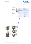
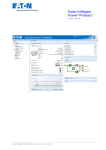
www.mgeops.com
Enterprise Power
Manager
User’s Guide
E N E R G I Z E
Y O U R
E N T E R P R I S E
Enterprise Power Manager – User’s Guide – 34 003 822 XU / AP
www.mgeops.com
T H E
U N I N T E R R U P T I B L E
P O W E R
Enterprise Power Manager – User’s Guide – 34 003 822 XU / AP
P R O V I D E R
Page 2/65
www.mgeops.com
Table of Contents
1
2
Introduction.................................................................................................................. 5
Installation and Configuration Procedure ................................................................. 7
2.1
Installation Prerequisites ..................................................................................................................7
2.1.1
On the System Hosting « Enterprise Power Manager »...............................................................7
2.1.2
On the System that Displays Web-based Graphical User Interface.............................................7
2.2
Quick Start ..........................................................................................................................................8
2.3
Installation Procedure .....................................................................................................................10
2.3.1
Configuration and Supervision....................................................................................................11
2.3.2
Installation Result .......................................................................................................................11
2.4
Uninstalling The Product ................................................................................................................12
2.5
Upgrading The Product ...................................................................................................................12
3
Settings ...................................................................................................................... 13
3.1
Configure the MGE Network Management Cards (SNMP/Web) or Proxies................................13
3.2
Enterprise Power Manager Settings ..............................................................................................13
3.2.1
Discover the Power Devices Connected on the Network...........................................................13
3.2.2
Define Power Device Groups .....................................................................................................14
3.2.3
Assign the Power Devices to the Groups ...................................................................................15
3.2.4
Applications.................................................................................................................................16
3.2.5
Configure Notifications................................................................................................................17
3.2.6
Configure User Accounts............................................................................................................19
3.2.7
Consult System Log....................................................................................................................20
3.2.8
Checking for Upgrades ...............................................................................................................21
3.2.9
Restart Engine ............................................................................................................................22
4
Operation.................................................................................................................... 23
4.1
Standard Supervision ......................................................................................................................23
4.1.1
Panel Organization .....................................................................................................................23
4.1.2
UPS Events list ...........................................................................................................................24
4.1.3
Access to the monitoring interface..............................................................................................26
4.1.4
List view ......................................................................................................................................27
4.1.5
Detailed view:..............................................................................................................................28
4.1.6
Powered Applications View ........................................................................................................30
4.2
Customized Graphic View...............................................................................................................31
4.2.1
Introduction .................................................................................................................................31
4.2.2
Steps for creating a "first" Graphic View.....................................................................................31
4.2.3
Connecting and moving Flows....................................................................................................32
4.2.4
Build and use a supervision diagram..........................................................................................33
4.2.5
Graphic objects in the Models tool box.......................................................................................34
4.2.6
Allocating a "name" to a "Power Device" or an "Application" .....................................................38
4.2.7
Inserting a background image ....................................................................................................39
4.2.8
Examples of Graphic Views........................................................................................................40
4.2.9
Electrical measurements of each module...................................................................................43
4.2.10 Server supervised data...............................................................................................................43
4.2.11 Colour codes for each module....................................................................................................44
4.2.12 Last Events / History / Statistics .................................................................................................47
Launching UPS Properties from “Enterprise Power Manager” .............................................................49
4.3
Devices Compatibility List ..............................................................................................................50
4.3.1
Eaton & MGE Office Protection Systems Devices .....................................................................50
4.3.2
Computers ..................................................................................................................................50
4.3.3
Other Devices .............................................................................................................................51
4.3.4
Other devices supervision ..........................................................................................................52
4.4
Performances for Enterprise Power Manager...............................................................................59
4.4.1
Gold Edition ................................................................................................................................59
4.4.2
Discovery time: ...........................................................................................................................59
T H E
U N I N T E R R U P T I B L E
P O W E R
Enterprise Power Manager – User’s Guide – 34 003 822 XU / AP
P R O V I D E R
Page 3/65
www.mgeops.com
4.5
5
6
7
Maintenance .....................................................................................................................................60
FAQ and Error messages.......................................................................................... 62
Glossary ..................................................................................................................... 63
Acknowledgements ................................................................................................... 64
T H E
U N I N T E R R U P T I B L E
P O W E R
Enterprise Power Manager – User’s Guide – 34 003 822 XU / AP
P R O V I D E R
Page 4/65
www.mgeops.com
1 Introduction
MGE supervision tool is called "Enterprise Power Manager".
"Enterprise Power Manager" discovers all MGE UPSs connected to the network (either by means of a card or a
proxy). For the detailed list of compatible solutions, please refer to the paragraph 4.3 (Equipment
Compatibility List) hereafter.
This document describes the steps to install and use “Enterprise Power Manager”.
NEW functions of Enterprise Power Manager V2:
Z A simple and very powerful representation mode lets you create your electrical supervision diagram
using a web browser.
Z Enterprise Power manager V2 also allows the supervision of servers hosting the Network Shutdown
Module V3 application.
Supervision using Enterprise Power Manager
Z
Easy supervision of a group of UPS systems
Enterprise Power Manager is a system for managing networked UPSs more easily and at lower cost
than the major NMS platforms, and is dedicated to power management functions.
The manager of the UPS group has an overall, consolidated view of the main operating parameters of all
the UPS systems. This information is accessible from any workstation using a standard Web browser.
It can easily sort the UPSs according to the most critical parameters (location, system status, etc).
Alarms are centralized and transmitted, if required, by e-mail, SMS or broadcast. The log of events and
operations helps preventive management of the various UPSs.
Z
Simple to deploy, and using industry standards
When installed, Enterprise Power Manager can carry out a scan for all the UPSs from MGE and other
suppliers supporting the standard UPS MIB.
The user is then presented with a layout that can be easily configured, as required, according to the type
of UPS, location, operating status, etc.
Z
An overall view of the UPS network & advanced power management
Clicking on a UPS in the layout shows detailed information about the operating and configuration
parameters in a dedicated window.
Enterprise Power Manager uses Secure Sockets Layer (SSL) and several levels of password
(administrator, user, etc) for complete security.
Z
Simple, economical and scalable
A version limited to 5 UPSs is available free of charge on the MGE web site. This version can also be
used to evaluate the software for a more extensive network before purchasing an Enterprise Power
Manager for 50 or more UPS systems.
T H E
U N I N T E R R U P T I B L E
P O W E R
Enterprise Power Manager – User’s Guide – 34 003 822 XU / AP
P R O V I D E R
Page 5/65
www.mgeops.com
This document applies to the 3 commercial versions of Enterprise Power Manager:
Z
5-node
available free of charge on MGE web site
and
on Solution Pac 2 CD-ROM
T H E
Z
50-node
Z
Unlimited node available on Enterprise Power Manager Gold
Edition CD-ROM.
Part number 66924
U N I N T E R R U P T I B L E
available on Management Pac 2 CD-ROM Part
number 66923
P O W E R
Enterprise Power Manager – User’s Guide – 34 003 822 XU / AP
P R O V I D E R
Page 6/65
www.mgeops.com
2 Installation and Configuration Procedure
2.1 Installation Prerequisites
2.1.1
On the System Hosting « Enterprise Power Manager »
Enterprise Power Manager can be installed on Windows 2000/XP (Home or Pro) / 2003 / Vista / 2008
Notes:
Z Windows_SP2: We advise you against the use of Windows XP Service Pack 2 that only authorizes 10
simultaneous network connections. The discovery process will be much longer due to this limitation. (cf.
Discovery time paragraph)
For Windows XP Service Pack 2, we advise you to use the new Quick Scan feature
Z
For Windows XP SP2 you have to configure the network ports 80 and 443 (http & https) on the Windows
Firewall
Z
To avoid network access conflicts, we advise you against installing the Enterprise Power Manager on a
machine that also hosts a Network Management System ( e.g. HP-Openview, CA Unicenter, …)
Z
To avoid access conflicts on Network ports 80 & 443 (Http & Https), we advise you against installing the
Enterprise Power Manager on a machine that also hosts a Web server using these ports.
If really necessary, these ports can be changed in
C:\Program Files\MGE\EnterprisePowerManager\bin\webserver\conf\Config.pi3
2.1.2
On the System that Displays Web-based Graphical User Interface
The Enterprise Power Manager graphical interface can be accessed remotely using a simple Web browser.
Access to this interface is secured through SSL connection (default configuration) and can also be secured
through Login & password.
The Enterprise Power Manager graphical interface has been tested with:
Z Mozilla Firefox 1.5 & 2.0 (recommended for better performance)
Z Microsoft Internet Explorer V6 & 7
T H E
U N I N T E R R U P T I B L E
P O W E R
Enterprise Power Manager – User’s Guide – 34 003 822 XU / AP
P R O V I D E R
Page 7/65
www.mgeops.com
2.2 Quick Start
To start device supervision in 5 minutes, please perform the following steps:
Z
Step 1 (Installation)
On a Windows 2000/XP(Home or Pro)/2003/Vista/2008 machine, execute the “Enterprise Power
Manager” package under an administrator account.
Note: If you use Windows XP Service Pack 2 or a Network Management System, please refer to the
pre-requisites.
Z
Step 2 (Configuration)
From the Settings -> Auto discovery page, click on the Discover button.
With this quick scan operation, you will discover within a few seconds: Network Management Cards ref
66074 & 66244 & 66102 /BA and Network Shutdown Module V3
For the other devices, please perform the discovery based on IP address ranges
Z
Step 3 (Optional configuration recommended for large installations)
In the Settings-> Groups page, create one or several power device groups.
In the Settings-> Power Device page, assign the discovered devices to the previously created groups.
In the Settings-> User Accounts page, assign the access rights through “login and password”
Z
Step 4 (Operation)
The Status tab allows you to supervise the current state of the compatible power devices.
The Report tab allows you to view the device events.
For these 2 tabs, the left tree allows you to access information device by device or group by group.
T H E
U N I N T E R R U P T I B L E
P O W E R
Enterprise Power Manager – User’s Guide – 34 003 822 XU / AP
P R O V I D E R
Page 8/65
www.mgeops.com
T H E
U N I N T E R R U P T I B L E
P O W E R
Enterprise Power Manager – User’s Guide – 34 003 822 XU / AP
P R O V I D E R
Page 9/65
www.mgeops.com
2.3 Installation Procedure
Z
Download the package from http://download.mgeops.com
(select Download tab, and then Software menu item)
Or execute the software installer from a MGE CD-ROM containing the product
Z
Execute the package and follow the instructions.
At the end of the installation, your Web Browser is started with an HTML page for Auto discovery
settings.
Auto Discovery window
Two possibilities are offered to you for network discovery:
Z First possibility:
From the Settings -> Auto discovery page, click on the Discover button.
With this quick scan operation, you will discover the following devices and applications within a few
seconds:
> Network Management Card ref 66074 & 66244 & 66102 (/BA min.)
> Network Shutdown Module V3
Quick Scan window
For the other devices, please perform the discovery based on IP address ranges (as explained
hereafter)
T H E
U N I N T E R R U P T I B L E
P O W E R
Enterprise Power Manager – User’s Guide – 34 003 822 XU / AP
P R O V I D E R
Page 10/65
www.mgeops.com
Z
Second possibility:
From the Auto discovery page, enter the IP address range concerning the devices you want to monitor:
> enter the first IP address of the range in the first area
> enter the last IP address of the range in the second area
> click on Add new range button
> and click on Discovery now button (cf Windows_SP2 Note)
Notes:
Z A bar will be displayed to inform you about the progress of the discovery process. (cf Windows_SP2
Note)
Z You can enter several IP address ranges and start the auto-discovery on the selected range.
Z You can assign a different community name to each IP range.
2.3.1
Z
Configuration and Supervision
Then 2 possibilities are offered to you:
> you can create groups and assign devices to the group (cf. 4. Settings chapter)
> or you can directly view the "Enterprise Power Manager" main screen. Click on the Status tab, and
you will view the discovered devices.
2.3.2
Installation Result
Z
If you install a new EPM version without uninstalling the old one you will keep your database and your
product information (number of nodes, …)
Z
At the end of the installation, the following shortcuts are created in the group:
Start -> Programs -> MGE Office Protection Systems -> Enterprise Power Manager
Name
Z
Z
Description
Starts the main "Enterprise Power Manager" graphical
interface
Uninstalls the Program
A service called « MGE Enterprise Power Manager – Acquisition engine» is also created for the
Database Acquisition Engine. This program continuously polls the status of the MGE devices connected
on the network. This service automatically starts on machine bootup.
If for any reason this service is stopped, a Warning message (« Acquisition engine is stopped ») is
displayed at the bottom of the main graphical interface. You can restart it from the Windows services or
from the “Settings -> Restart Engine” window.
A service called « MGE Enterprise Power Manager – Web Server» is also created and started.
T H E
U N I N T E R R U P T I B L E
P O W E R
Enterprise Power Manager – User’s Guide – 34 003 822 XU / AP
P R O V I D E R
Page 11/65
www.mgeops.com
2.4 Uninstalling The Product
Z
Z
From the Add/Remove programs item of the control panel, execute the "Enterprise Power Manager"
package.
You can also uninstall from the shortcuts:
Start -> Programs -> MGE Office Protection Systems -> Enterprise Power Manager -> Uninstall
This will remove the database.
2.5 Upgrading The Product
Please refer to the Checking for Upgrades Paragraph.
T H E
U N I N T E R R U P T I B L E
P O W E R
Enterprise Power Manager – User’s Guide – 34 003 822 XU / AP
P R O V I D E R
Page 12/65
www.mgeops.com
3
Settings
3.1 Configure the MGE Network Management Cards (SNMP/Web) or Proxies
Each MGE Network Management Card or Proxy must have a valid IP address (or a
DNS name) in the range that you have entered for auto-discovery. Refer to the list of
compatible power devices.
“Enterprise Power Manager” automatically receives the alarms (through polling) without
specific configuration on the cards or proxies.
3.2 Enterprise Power Manager Settings
Start the "Enterprise Power Manager" main graphical interface from the previously created shortcut, then
click on the Settings Tab.
3.2.1
Discover the Power Devices Connected on the Network
Please refer to the Installation procedure
T H E
U N I N T E R R U P T I B L E
P O W E R
Enterprise Power Manager – User’s Guide – 34 003 822 XU / AP
P R O V I D E R
Page 13/65
www.mgeops.com
3.2.2
Define Power Device Groups
When you have to monitor large configurations, it is interesting to define several device
groups and then to assign the devices to these groups.
You can select any criteria you want in order to organize your devices (i.e.
geographical, organizational, ..)
When you have to monitor large configurations, it is interesting to define several device groups and then to
assign the devices to these groups.
You can select any criteria you want in order to organize your devices (i.e. geographical, organizational, ..)
From the Settings tab, select the Groups menu item, then perform these steps:
Z
Z
Z
Z
in this page, enter any group name: e.g. “Server Room" ;
select the parent group if you want a multi-level organization
then click on "Create new group" ;
Note: the created groups appear in this page, so that you can modify or remove them.
Groups window
T H E
U N I N T E R R U P T I B L E
P O W E R
Enterprise Power Manager – User’s Guide – 34 003 822 XU / AP
P R O V I D E R
Page 14/65
www.mgeops.com
3.2.3
Assign the Power Devices to the Groups
Now you can assign the devices to one of the created groups.
From the Settings tab, select the Devices menu item, then perform these steps:
Z
Z
assign each device of the Device List to one of the previously created groups;
click on the Save Changed Items button to apply the modifications.
Power Devices window
Now if you go back to the Status Tab, you will notice that the left tree takes into account your configuration.
Under Root , select "DataCenter" (only the DataCenter devices will be displayed).
Notes:
Z From this screen, you can also modify the Name of the device and its Location. The modified values will
be internal to the Enterprise Power Manager and will not be uploaded on the device.
Z You have the possibility to remove the devices you don’t want to monitor through the Enterprise Power
Manager.
Z A web link to the device is suggested.
T H E
U N I N T E R R U P T I B L E
P O W E R
Enterprise Power Manager – User’s Guide – 34 003 822 XU / AP
P R O V I D E R
Page 15/65
www.mgeops.com
3.2.4
Applications
With "Enterprise Power Manager V2", the servers (or other computers) hosting a "Network
Shutdown Module V3" application can be supervised.
Z
Z
Z
Z
From this screen, application names (Name) can be changed. The new values will be internal to the
Enterprise Power Manager software.
Applications you do not wish to supervise with Enterprise Power Manager can be removed.
A Web link to the equipment is proposed.
Click on the Save changed application(s) button to save the changes.
Application management window
T H E
U N I N T E R R U P T I B L E
P O W E R
Enterprise Power Manager – User’s Guide – 34 003 822 XU / AP
P R O V I D E R
Page 16/65
www.mgeops.com
3.2.5
Configure Notifications
You can define the way users will be notified when device events happen.
From the Settings tab, select the Notifications item; the following channels are
available:
Z E-mail
Z Broadcast
Z Execute script/program
Z Alarms Sound Options
Notifications window
Note on Notification Level parameter:
With this parameter, you can filter the notification according to the event level. Refer to the event list provided
hereafter. Note that if you select “Critical” as filter you will also receive the associated “Normal” event
informing that the device status changes from “Critical” to “Normal”.
E-mail:
To receive emails on UPS events:
Z you have to indicate the SMTP server address and recipient e-mail address;
Z you can filter the email notification according to:
> the event level.
> the device group (the sub groups are also included);
Z then you have to click on Add new e-mail notification.
For advanced use:
T H E
U N I N T E R R U P T I B L E
P O W E R
Enterprise Power Manager – User’s Guide – 34 003 822 XU / AP
P R O V I D E R
Page 17/65
www.mgeops.com
Z
Z
you can Customize subject if you have to translate e-mail into SMS for example,
you can specify that you want to receive a consolidation of the alarms that occurred during a delay that
you can choose (if you specify no delay, each alarm will generate an e-mail)
Broadcast:
To receive broadcast on UPS events (through Netsend command):
Z you have to indicate the recipient (It can be either a Windows machine name or a user account);
Z you can filter the broadcast notification according to:
> the event level
> the device group (the sub groups are also included);
Z then click on Add new broadcast notification.
Note: Check that “Windows Messenger service” is started on the local and on the remote Windows
machines. On Windows XP, 2003, 2008 it is not started by default.
Execute script/program:
To execute a program upon UPS events:
Z you should firstly indicate its path;
Z you can filter the program execution according to:
> the event level
> the device group (the sub groups are also included);
Z then click on Add new execute command.
Note: The program is executed under SYSTEM account.
Alarms Sound Options:
To execute a sound alarm upon UPS events:
Z
Z
you can filter the sound alarm according to the event level;
then you have to click on Set button.
Note: These alarms are executed in the Web Browser context, so the Web browser has to be opened and
pointing to a Web page of the Enterprise Power Manager.
T H E
U N I N T E R R U P T I B L E
P O W E R
Enterprise Power Manager – User’s Guide – 34 003 822 XU / AP
P R O V I D E R
Page 18/65
www.mgeops.com
3.2.6
Configure User Accounts
You can configure several user accounts.
From the Settings tab, select the User accounts item, then perform the following steps:
Z
Z
Z
enter the User Login and the User password:
select the User’s Rights level. The following levels are available:
> Visualization – Management (the user will be able to access all the tabs)
> Visualization (the user will only access the Status, Reports, Maintenance and About tabs)
click on Create new user button
User Accounts window
Note: When you create user accounts with this interface, a “Logout” link appears in the right top section of
the window. Use this link to exit from the application.
T H E
U N I N T E R R U P T I B L E
P O W E R
Enterprise Power Manager – User’s Guide – 34 003 822 XU / AP
P R O V I D E R
Page 19/65
www.mgeops.com
3.2.7
Consult System Log
You can have access to the Enterprise Power Manager internal log to explain some unexpected behavior.
With the Export system log, you can save this log data as a file (csv is a file format useable with Microsoft
Excel).
From the System menu, select System Log to access the information:
System Log window
Z
Advanced trace:
We warn you against the use of disk space for this Trace mode.
To validate verbose mode :
> in the bin/dae directory of the application, rename the file called debugMode.off into debugMode.on,
> view the trace in the file called traceDebug.txt in the same directory.
To stop verbose mode :
> in the bin directory of the application, rename the file called debugMode.off into debugMode.on,
> restart the service MGE Enterprise Power Manager - Acquisition engine.
T H E
U N I N T E R R U P T I B L E
P O W E R
Enterprise Power Manager – User’s Guide – 34 003 822 XU / AP
P R O V I D E R
Page 20/65
www.mgeops.com
3.2.8
Checking for Upgrades
This function gives you access to MGE Office Protection Systems software updates.
Your Enterprise Power Manager will always be up to date if you select the Check automatically option.
When a new software version is detected on www.mgeops.com, just follow the wizard instructions.
Note: You will keep database information with this operation
Check for upgrade window
T H E
U N I N T E R R U P T I B L E
P O W E R
Enterprise Power Manager – User’s Guide – 34 003 822 XU / AP
P R O V I D E R
Page 21/65
www.mgeops.com
3.2.9
Restart Engine
With this function, you can remotely restart the Enterprise Power Manager acquisition engine. This function
can be useful to detect device configuration changes or to reboot the acquisition Engine in case of any
unexpected stop.
Restart Engine window.
T H E
U N I N T E R R U P T I B L E
P O W E R
Enterprise Power Manager – User’s Guide – 34 003 822 XU / AP
P R O V I D E R
Page 22/65
www.mgeops.com
4 Operation
4.1 Standard Supervision
4.1.1
Panel Organization
The supervision window is made of several areas as displayed below:
Tabs:
|Status | Report | Maintenance | Settings | About | Logout
Menu
View(s) (List / Detailed / Graphic / Graphic Editor / Powered
Applications)
Device status:
Last Events:
Menu area:
This menu is a tree with Root as base group that provides the following features to manage large
configurations:
Z from this area, you can filter the information access (should you have previously created groups and
assigned the devices to these groups).
For example, if you select a specific group, only the devices assigned to this group (and sub groups) will
appear in the List View; if you select a specific device, only the information relative to the selected
device will appear in the Detailed View.
Note: once you have selected a device or a group in the Menu area, you can switch from tab to tab to
view the Status, the Reports, the Maintenance information concerning the selected item.
E.g. You can check the alarm list for a specific device group.
Z
the status severity is propagated to the parent group.
Z
if an icon is blinking, this means that new events have appeared that are not yet acknowledged. Once
these events have been acknowledged, blinking stops.
Note: On some browsers (e.g. IE on Windows Server 2003 and 2008), the animated pictures are
disabled by default. You have to change this setting to view the icons blinking.
Devices status area: (always visible)
From this area, you have access to the following information:
Z status breakdown of the devices;
Z
clicking on one of the icons will change it (the
symbol is added ).
This means that we filter the access to the devices from this category. A device list view will be displayed
when clicking on the icon.
The filter function disappears by clicking again on the
T H E
U N I N T E R R U P T I B L E
P O W E R
Enterprise Power Manager – User’s Guide – 34 003 822 XU / AP
icon (the icon will disappear).
P R O V I D E R
Page 23/65
www.mgeops.com
Device icon severity:
The icon in the different views represents the severity status of the managed device.
Icon
or
device status
Normal. The status of the device is normal.
Warning. A problem is active on the device. Your application is
still protected.
Critical. A serious problem occurs on the device. This problem
requires an urgent action. Your application is NO LONGER
protected.
Communication lost between the card/proxy agent and
Enterprise Power Manager.
Or communication lost between the device and the
Card/Proxy.
Not managed. Due to license limitation this device is not
supervised (possible for 5 nodes or 50 nodes versions)
Last events area: (always visible)
From this area, you have access to the following information:
Z breakdown of recorded events according to their severity;
Z list of events with the same severity level when clicking on the icon.
Z
symbol is added).
clicking on one of the icons will change it (the
This means that access to the events from this category is filtered. An Events list view will be displayed
when clicking on the icon.
Z
The filter function disappears by clicking again on
4.1.2
icon (the icon will disappear).
UPS Events list
The icons in the different views represent the event severity.
Icon
Event status
Normal. With this event, the device is coming back to a normal status.
Event list:
Z Communication with "Management Card Proxy" is restored
Z Maintenance task is done
Z The system is powered by the utility
Z The UPS output is on
Z Communication restored with UPS
Z Battery OK
Z UPS returns to normal load
Z UPS OK
Z Bypass : Return on UPS
Z End of low battery alarm
Z Outlet group 1 is on
Z Outlet group 2 is on
Z Communication failure with environment sensor
T H E
U N I N T E R R U P T I B L E
P O W E R
Enterprise Power Manager – User’s Guide – 34 003 822 XU / AP
P R O V I D E R
Page 24/65
www.mgeops.com
Z
Z
Z
Z
Z
Z
Z
Communication restored with environment sensor
Humidity is in normal range
Temperature is in normal range
Input #1 closed
Input #1 opened
Input #2 closed
Input #2 opened
Warning. A problem occurred on the device. Your application is still protected.
Event list:
Z Maintenance operation is needed"
Z The system is powered by the UPS battery"
Z Output on automatic bypass
Z Output on manual bypass
Z Humidity is below low threshold"
Z Humidity is above high threshold"
Z Temperature is below low threshold"
Z Temperature is above high threshold"
Critical. A serious problem occurred on the device. This problem requires an
urgent action. Your application might NOT BE powered anymore.
Event list:
Z UPS output is off
Z Outlet group 1 is off
Z Outlet group 2 is off
Z Battery fault
Z UPS overload
Z UPS fault
Z Low battery alarm
Z System shutdown in progress...
Communication lost between the card/proxy agent and the Enterprise Power
Manager.
Or communication lost between the device and the Card/Proxy.
Event list:
Z Communication with "Management Card Proxy" has failed (Warning)
Z Communication failure with UPS (Warning)
T H E
U N I N T E R R U P T I B L E
P O W E R
Enterprise Power Manager – User’s Guide – 34 003 822 XU / AP
P R O V I D E R
Page 25/65
www.mgeops.com
4.1.3
Access to the monitoring interface
To monitor MGE devices already discovered on the network, start the main “Enterprise Power Manager”
interface. You can access locally or remotely the same interface.
4.1.3.1 Local access
Z
From the system where the supervisor is installed, you can use the following shortcut:
Start -> Programs -> MGE Office Protection Systems -> Enterprise Power Manager ->Enterprise Power
Manager
4.1.3.2 Remote access
Z
From a remote machine, you can type the following URL in a Web browser
https://<name or IP address of computer hosting EPM>/PowerManager/
or
http://<name or IP address of computer hosting EPM>/PowerManager/
Note: The Web server is “case sensitive” for the URL
Z
In SSL mode, accept the certificate (by clicking on Yes)
To install the certificate on IE7 for Vista, you need
to perform the following steps:
> Run IE as an administrator (Right-click the
desktop icon)
> Visit the EPM site.
> Click through the certificate error
> Click the "Certificate Error" button in the
address bar.
> Click View Certificate
> Click Install Certificate
> Unlike on XP, you must click the “Place all
certificates in the following store” radio button,
and choose the “Trusted Root Certification
Authorities” store. If you don’t do this, the
certificate goes in your personal store, and it isn’t
trusted by IE.
Accepting the SSL Certificate
Z
Enter the Login and Password (optional)
Z
Select the Status tab, and the following page appears:
(If you select in the menu a group icon, a list view appears. If you select in the menu a device Icon, a
detailed view appears)
T H E
U N I N T E R R U P T I B L E
P O W E R
Enterprise Power Manager – User’s Guide – 34 003 822 XU / AP
P R O V I D E R
Page 26/65
www.mgeops.com
4.1.4
List view
List of MGE UPSs in Root group.
The following UPS information is displayed in this page:
Z
Z
Z
Z
Z
Z
Z
Status
Name
Product name
Location
Group
Load Level
Link
this icon represents the severity of the monitored device;
the IP address (or the DNS name)
the MGE product name
the device location (value of syslocation object or value configured in Device page)
the group assigned to the device
the output level of the device
link to the device Web site (if available)
Note: You can sort your device list by clicking on the column titles (Status / Name / Product Name/ Location /
Group / Load Level)
A second click will reverse the sorting order.
T H E
U N I N T E R R U P T I B L E
P O W E R
Enterprise Power Manager – User’s Guide – 34 003 822 XU / AP
P R O V I D E R
Page 27/65
www.mgeops.com
4.1.5
Z
Detailed view:
Select one of the device in the left menu and the following “detailed view” page appears:
UPS Detailed View.
The following device information is displayed in this page:
Z
Z
Z
Z
Z
Device
IP address
Link
Location
Z Contact
Z Group
Z Serial Number
Status
Z Communication
Z Power source
Z Battery
Z Output
the DNS name (or IP address) is displayed near this icon
the commercial product name
the IP address of the device
link to the device Web site (if available)
the device location (value of syslocation object or can also be configured in the
Device page )
the device contact (value of syscontact object or can also be configured in the
Device page )
the group assigned to the device (Clicking on the Icon will display the group list
view)
The device Serial Number (if available)
Device communication status (OK / Network Communication Failure / device
Communication Failure)
AC Power / Battery
Charging / Discharging / Need Replacement
Main output status (ON/OFF/Internal Failure/On Automatic Bypass/Manual By
Pass/Overload)
or output outlet status (ON/OFF)
Values
Z Output Load Level
the output load level of the device
Z Battery capacity
Battery capacity of the device
Z Remaining backup time the device remaining backup time
Environment: Environment Sensor (optional)
T H E
U N I N T E R R U P T I B L E
P O W E R
Enterprise Power Manager – User’s Guide – 34 003 822 XU / AP
P R O V I D E R
Page 28/65
www.mgeops.com
Z
Z
Z
Z
Temperature
Humidity
Input #1
Input #2
Sensor temperature (in °C)
Humidity level
Status of first contact (open / closed)
Status of second contact (open / closed)
Note that this view is impacted when any device status is affected,
T H E
U N I N T E R R U P T I B L E
P O W E R
Enterprise Power Manager – User’s Guide – 34 003 822 XU / AP
P R O V I D E R
Page 29/65
www.mgeops.com
4.1.6
Powered Applications View
Selecting Powered Applications View from the scroll down list at the top right of the screen displays a list of
computer servers:
Z powered by a UPS of the selected group
Z and hosting a Network Shutdown Module V3 module
The following information appears in this page:
Z Status
Z Name
Z
Z
Z
Z
This icon represents the status criticality of the server.
Value configured in the Applications screen (by default this is an IP address or a DNS
name).
Description
Machine operating system.
Run time
Operating time in the event of a utility supply loss.
Shutdown duration Duration, in seconds, needed by the system to carry out its shutdown procedure.
Link
Link to the Web supervision interface of the Network Shutdown Module V3 module.
T H E
U N I N T E R R U P T I B L E
P O W E R
Enterprise Power Manager – User’s Guide – 34 003 822 XU / AP
P R O V I D E R
Page 30/65
www.mgeops.com
4.2 Customized Graphic View
4.2.1
Introduction
This simple and very powerful representation mode lets you create electrical supervision diagrams using a
Web browser. Here you will find graphic view examples.
4.2.2
Steps for creating a "first" Graphic View
Z
Z
Select a UPS group from the menu in the left zone of the
screen.
From the scroll down list (at the top right of the screen)
change from List View to Graphic View Editor.
When in Graphic View Editor mode, a grid appears on the
screen background to help you position the graphic objects.
From the Models tool box, select a category of graphic objects.
e.g. select the Connections objects.
In this section there are:
Z horizontal electrical flows
Z vertical electrical flows
Z power sources
Z application loads
From the tool box, use the mouse to select the graphic objects
(one after the other) and drag and drop them onto the grid.
You are now able to create the following first diagram:
“A source electrically powers a load.”
To remove objects from the diagram:
Z select the graphic objects using the mouse (one after the
other)
Z drag them into the Garbage tool box
Z the object is deleted as soon as it is dropped
Note: Double-clicking on the garbage-can deletes the entire
view.
T H E
U N I N T E R R U P T I B L E
P O W E R
Enterprise Power Manager – User’s Guide – 34 003 822 XU / AP
P R O V I D E R
Page 31/65
www.mgeops.com
4.2.3
Connecting and moving Flows
In Graphic View Editor mode, the mouse cursor changes shape depending on where it is positioned on the
flow:
The flows (horizontal or vertical) can be moved when picked-up in the middle. Cursor
shape for a "Move" operation.
The flows (horizontal or vertical) can be stretched when picked-up at their ends. Cursor
shape for a "Stretch" operation
Important Note: Flows can only be connected together at their ends.
To help in detecting incorrect connections, a segment that is only connected at one end is white (instead of
yellow).
Examples of correct and incorrect connections
T H E
U N I N T E R R U P T I B L E
P O W E R
Enterprise Power Manager – User’s Guide – 34 003 822 XU / AP
P R O V I D E R
Page 32/65
www.mgeops.com
4.2.4
Z
Z
Build and use a supervision diagram
The Graphic View supervision mode allows the diagram to be used (in Graphic View Editor mode).
The Graphic View Editor mode allows an electrical supervision diagram to be built, changed or
customised:
To go to "Graphic View Editor" mode:
From the scroll down list (at the top right of the screen) change
from List View to Graphic View Editor.
In the Graphic View Editor mode, this grid appears on the
screen background to help you position the graphic objects:
The positions of objects on the diagram are saved as it is builtup (warning: it is not possible to return to a previously saved
version of your diagram).
To quit "Graphic View Editor" mode:
From the scroll down list (at the top right of the screen) change
from Graphic View Editor to Graphic View.
In Graphic View Editor mode, the three tool boxes (Models, Properties and Garbage) appear.
In Graphic View Editor mode, you can:
Z create new objects in the Graphic View by dragging-dropping from the Models tool box
Z Allocate a "Name" (or IP address) to a device using the Properties tool box
Z Insert a background image using the Properties tool box
Z move graphic objects (to connect electrical flow objects for example)
Z Remove graphic objects from the card
Notes:
Z By using the mouse, the three tool boxes (Models, Properties and Garbage) can be moved to a zone of
your choice (drop & drag operation).
Z The size of these boxes can be minimized and maximized by clicking in the -/+ zone of the title bar.
T H E
U N I N T E R R U P T I B L E
P O W E R
Enterprise Power Manager – User’s Guide – 34 003 822 XU / AP
P R O V I D E R
Page 33/65
www.mgeops.com
4.2.5
Graphic objects in the Models tool box
The following graphic objects are available in the Models
tool box:
Z
Power Devices icons:
Generic icon for a power device contained in the Enterprise Power
Manager compatibility list (UPS, Static Transfer Switch, Switch PDU,
Midspan, etc).
This macroscopic icon provides:
Z device status and name
Z access to the last view selected for the equipment (Detailed View or
Graphic View)
Graphic icon (small size) for a power device (UPS only). This
representation provides:
Z device status and name
Z device graphic
Z the electrical connections
Z the controlled outlets(*)
Z access to the last view selected for the equipment (Detailed View or
Graphic View)
Graphic icon (large size) for a power device (UPS only).
This representation provides the same information as the icon above.
Note (*): If the UPS has controlled outlets, several electrical flows are proposed at the output. They
represent the status of the main group, the controlled outlets 1 group, the controlled outlets 2 group, etc.
Z
Applications:
Graphic icon for a computer server with single-input power supply.
This representation provides:
Z the name and status of the server hosting a Network Shutdown
Module V3
Z server graphic (**)
Z the electrical connections (power supply)
Z a link to the supervision interface
T H E
U N I N T E R R U P T I B L E
P O W E R
Enterprise Power Manager – User’s Guide – 34 003 822 XU / AP
P R O V I D E R
Page 34/65
www.mgeops.com
Graphic icon for a computer server with dual input power supplies.
This representation provides:
Z the name and status of the server hosting a Network Shutdown
Module V3
Z server graphic (**)
Z the electrical connections (two power supplies)
Z a link to the supervision interface
Graphic icon for an "industrial process" type critical application
This representation provides:
Z a representation of a "Network Shutdown Module" type application
without communication module
Z the possibility of customizing the application name or application
graphic (**) using the Properties tool box
Note (**): The graphic representation of one of these applications can be changed by selecting the
application and then choosing another image from the Properties tool box.
Changing server graphic representation
Z
Electrical Connections:
Electrical flow icon (horizontal or vertical).
This object can have different status.
Electrical power source. This object can have different status.
Electrical load. This object can have different status.
T H E
U N I N T E R R U P T I B L E
P O W E R
Enterprise Power Manager – User’s Guide – 34 003 822 XU / AP
P R O V I D E R
Page 35/65
www.mgeops.com
Z
Block diagrams for single-phase products:
This representation allows the following to be displayed:
Z
current flow in the device
Z
the different status of each module (by colour code)
Z
single-phase electrical measurements associated with each module
Z
the status of controlled outlets (*)
Block diagram of a single-phase On-Line UPS with 1 incoming supply.
Block diagram of a Line Interactive or Off-Line UPS with 1 incoming
supply.
Z
Block diagrams for three-phase products (UPS and Static Transfer Switch):
This representation allows the following to be displayed:
Z
current flow in the device
Z
the different status of each module (by colour code)
Z
three-phase electrical measurements associated with each module (except for STS)
Block diagram of a three-phase UPS with 2 incoming supplies.
Block diagram of a three-phase source changeover device - "Static
Transfer Switch".
Block diagram of a three-phase UPS with 1 incoming supply
Block diagram of a Static Switch Cabinet (Device Supported as Beta)
T H E
U N I N T E R R U P T I B L E
P O W E R
Enterprise Power Manager – User’s Guide – 34 003 822 XU / AP
P R O V I D E R
Page 36/65
www.mgeops.com
Z
Miscellaneous objects:
To add customized labels to your graphic view, proceed
as follows:
Z take the graphic object Label and drag it to the
graphic view
Z select the object
Z select the text using the Properties tool box
Z this text is updated in the box when the "Enter" key
is pressed or when another object is selected
Z Note: the box can be re-sized
Note: In Graphic View supervision mode, two types of Web links are proposed:
External link to the power device or application Web server
Link in the supervisor to the last selected equipment view (Detailed View or Graphic
View)
T H E
U N I N T E R R U P T I B L E
P O W E R
Enterprise Power Manager – User’s Guide – 34 003 822 XU / AP
P R O V I D E R
Page 37/65
www.mgeops.com
4.2.6
Allocating a "name" to a "Power Device" or an "Application"
When in Graphic View Editor mode for a card, a "Name" must be allocated to each graphic object
representing a Power Device or an Application (computer server hosting a Network Shutdown Module).
Note: this "Name" is the value configured in the Power devices or Applications screens (by default this is an
IP address or DNS name).
Proceed as follows:
In the Models tool box:
Z select a category, e.g. Power Devices, and then
a graphic
Z using the mouse, drag and drop the object onto
the grid
Z
Z
Z
Z
click on the graphic object
the Properties tool box is refreshed with the
object properties
select a name from the scroll down list
the object is updated with the object's real
properties (Status, Device Name, etc)
To finalize the diagram:
Z from the Models tool box, select Applications
Z drag a server object onto the card and connect it
electrically to the UPS
Z allocate a "name" to the computer server
Z insert a background image
Z go to Graphic View Supervision mode
T H E
U N I N T E R R U P T I B L E
P O W E R
Enterprise Power Manager – User’s Guide – 34 003 822 XU / AP
P R O V I D E R
Page 38/65
www.mgeops.com
4.2.7
Inserting a background image
When in Graphic View Editor mode on the card, you are able to import a background image.
Proceed as follows:
Z
Z
Z
Z
Z
Z
use a design software to create your own background
image (gif, jpg, etc format) suitably sized for your
supervision screen
For a 1280x1024 screen (recommended), image size is
1000x700
For 1280x1024 => image 760x460
click on the Upload button and add the new image file to
the list using the selection box
select this new image from the scroll down list
Z
Go to Graphic View Supervision mode
Z
T H E
click on the screen background grid
the Properties tool box is refreshed with the object
properties
select an image from the scroll down list
the result is displayed on the screen background
U N I N T E R R U P T I B L E
P O W E R
Enterprise Power Manager – User’s Guide – 34 003 822 XU / AP
P R O V I D E R
Page 39/65
www.mgeops.com
4.2.8
Examples of Graphic Views
You can make up your own supervision interface using the following graphics tools:
Z graphic objects to represent UPSs, applications, flows, etc
Z background image
Here are several examples of customized representations ranging from a macroscopic view of UPSs to a
detailed electrical view.
Example 1: UPS "Macroscopic" view
Note: A "macroscopic" view can be created in the "root" group. In a lower level group, a more detailed view
can be created with the same UPSs, as shown in the following examples:
T H E
U N I N T E R R U P T I B L E
P O W E R
Enterprise Power Manager – User’s Guide – 34 003 822 XU / AP
P R O V I D E R
Page 40/65
www.mgeops.com
Example 2: Intermediary customized view (floor drawing with building electrical distribution diagram)
Example3: Customized view of a computer room
T H E
U N I N T E R R U P T I B L E
P O W E R
Enterprise Power Manager – User’s Guide – 34 003 822 XU / AP
P R O V I D E R
Page 41/65
www.mgeops.com
Example4: Customized detailed electrical view
Example5: Customized detailed electrical view
This screen allows the following to be displayed:
Z status of device modules using colour codes
T H E
U N I N T E R R U P T I B L E
P O W E R
Enterprise Power Manager – User’s Guide – 34 003 822 XU / AP
P R O V I D E R
Page 42/65
www.mgeops.com
Z
Z
current flows in the electrical diagram
electrical measurements of each module
4.2.9
Electrical measurements of each module
When the mouse passes over a UPS module, the following contextual window appears. It automatically
disappears when the mouse is moved to another area.
By double-clicking on a module, the window is permanently displayed and its background colour changes.
By double-clicking again on the module in question, the window returns to its original status (displayed as
the mouse passes over it).
For three-phase UPSs, the following measurements are available for:
Z
The Normal AC input module
Z
The output module
Z
The battery
Z
The By-Pass AC module
For single-phase UPSs, the above measurements are only available for a single phase.
4.2.10 Server supervised data
When the mouse passes over the icon of a server hosting a Network Shutdown Module V3, the following
contextual window appears. It automatically disappears when the mouse is moved to another area.
T H E
U N I N T E R R U P T I B L E
P O W E R
Enterprise Power Manager – User’s Guide – 34 003 822 XU / AP
P R O V I D E R
Page 43/65
www.mgeops.com
By double-clicking on the server icon, the window is permanently displayed and its background colour
changes. By double-clicking again on this server, the window returns to its original status (displayed as the
mouse passes over it).
Supervised data of a Network Shutdown Module
The Status can have the following values:
Icon
Signification
Application protected (normal status)
Application Not Protected (e.g. the UPSs feeding the application are in By-Pass mode)
Loss of redundancy (e.g. the number of redundant UPSs is less than the desired one)
Loss of communication (between the "Enterprise Power Manager" and the "Network
Shutdown Module")
4.2.11 Colour codes for each module
Z
UPS modules:
AC/DC
Z
By-Pass or STS module
Colour
Green
Description
Status OK & Active
Red
Internal fault & Inactive
Grey
Status OK & Inactive
or Unknown
Battery module:
Symbol
Z
DC/AC
Colour
Green
Description
Status OK
Orange
Battery charge is less than 50%
Red
Battery fault or End-of-backup or End-of-battery-service-life pre-alarm
Grey
Battery status unknown
Electrical flows:
Symbol
T H E
Colour
Description
U N I N T E R R U P T I B L E
P O W E R
Enterprise Power Manager – User’s Guide – 34 003 822 XU / AP
P R O V I D E R
Page 44/65
www.mgeops.com
Yellow
Grey
White
Z
Current flow through the cable
Note: the object animation gives the direction of current flow
No current flow through the cable (voltage may be present)
Object not connected at one of its ends
This "abnormal" status provides help to detect connection errors in the electrical
diagram.
Electrical power source at UPS input:
Symbol
Colour
Green
Grey
Description
Source powered. Status OK
Source not powered or status unknown
Examples of combinations between flow status and power source status:
Green/
The electrical power source is powered and provides electrical flow
Yellow
Green/
The electrical power source is powered and does not provide electrical flow
Grey
Grey/
Power source not powered or status unknown and electrical flow not connected.
White
Z
Load at UPS output: (its status is linked to that of the UPS output status)
Symbol
Colour
Green
Description
Load powered and protected. Status OK
Red
Load not powered
Grey
Load status unknown
Examples of combinations between flow status and load status:
Yellow/
Load powered and protected
Green
Grey/
Load not powered
Red
White/
Load not powered or status unknown and electrical flow not connected
Grey
Z
Switches:
Symbol
Z
Colour
Green/
Yellow
Green/
Grey
Red/Grey
Description
Closed with current flowing through it (Status "normally closed")
Green/
Grey
Red/
Yellow
Red/Grey
Open with no current flowing through it (Status "normally open")
Closed with no current flowing through it (Status "normally open")
Grey/Grey
Unknown
Closed with no current flowing through it (Status "normally closed")
Open with no current flowing through it (Status "normally closed")
Closed with current flowing through it (Status "normally open")
Outlets:
T H E
U N I N T E R R U P T I B L E
P O W E R
Enterprise Power Manager – User’s Guide – 34 003 822 XU / AP
P R O V I D E R
Page 45/65
www.mgeops.com
Symbol
T H E
Colour
Green
Red
Description
Powered
Not powered
U N I N T E R R U P T I B L E
P O W E R
Enterprise Power Manager – User’s Guide – 34 003 822 XU / AP
P R O V I D E R
Page 46/65
www.mgeops.com
4.2.12 Last Events / History / Statistics
Select the Report tab, then Last Events Log and the following page appears:
Last Alarm list for the devices of your network area.
You can supervise following events:
Z the UPSs
Z the Network Shutdown Module
Z the Static Transfer Switch
Z the MGE Midspan & PowerDsine
Z the Switch PDU
Z the Rack Monitoring Systems
All the new alarms recorded for the selected device or for the selected group are stored in this log.
You can sort out the alarms according to the Level, the Name, the Date or the Message.
You have access to these 3 functions:
Z Print this log view … prints this information
Z
Export this log view … saves this log data in a file (csv is a file format useable with Microsoft Excel).
Z
Acknowledge event(s) removes events displayed on this view. This operation updates the Last events
count; now these events can be viewed from the History view
Note:
Z “Print” and “Acknowledge” functions will be performed on the 1000 last events
Z If more than 1000 Non-Acknowledged events are stored, the “Acknowledge all Events“ additional button
appears. This button is used to acknowledge non-displayed events.
T H E
U N I N T E R R U P T I B L E
P O W E R
Enterprise Power Manager – User’s Guide – 34 003 822 XU / AP
P R O V I D E R
Page 47/65
www.mgeops.com
History selection in the Combo box displays the Acknowledged and the non-Acknowledged events (see next
Window);
All the events recorded for the selected device or for the selected group are stored in this log.
History view for the selected devices of your network area.
The Statistics selection in the Combo box displays power event statistics (see next screen);
The statistics view applies to the selected device or to the selected group.
Statistics view for the selected devices of your network area.
T H E
U N I N T E R R U P T I B L E
P O W E R
Enterprise Power Manager – User’s Guide – 34 003 822 XU / AP
P R O V I D E R
Page 48/65
www.mgeops.com
Launching UPS Properties from “Enterprise Power Manager”
From the Status tab (list or detail), you can access the UPS properties Web Page for MGE proxies or cards
including an on-board web server (see detailed list in the following paragraph). Click on the web Link
.
associated to this icon
Running the “UPS properties" from Enterprise Power Manager.
T H E
U N I N T E R R U P T I B L E
P O W E R
Enterprise Power Manager – User’s Guide – 34 003 822 XU / AP
P R O V I D E R
Page 49/65
www.mgeops.com
4.3 Devices Compatibility List
Eaton - MGE Office Protection Systems has tested the compatibility of Enterprise Power Manager with the
following devices:
4.3.1
Eaton & MGE Office Protection Systems Devices
Eaton & MGE Office Protection Systems equipment
designation
Type
Network Management Card Minislot SNMP/Web – 66102
And associated Environment Sensor 66846
Network Management Card Transverse SNMP/Web –
66074
And associated Environment Sensor 66846
Network Management Card & Modbus/JBus – 66103
(through Ethernet Network) (****)
And associated Environment Sensor 66846
ConnectUPS- Minislot Network Management Card / ref
103006826
Eaton ePDU Monitored (*****)
UPS Option Card
Accessing
device Web
server
OK
UPS Option Card
OK
UPS Option Card
OK
UPS Option Card
Eaton
PDU Integrated
Communication Card
PDU Integrated
Communication Card
PDU Integrated
Communication Card
PDU Integrated
Communication Card
Midspan Integrated
Communication Card
Proxy
OK
Proxy (legacy)
UPS Option Card
(legacy)
UPS Option Card
(legacy)
UPS Option Card
(legacy)
UPS Option Card
(legacy)
UPS Option Card
(legacy)
na
OK
Eaton ePDU Managed (*****)
MGE Switched PDU NM - 68130 /
68134/56132/56134/56136/56138 (*)
MGE AmpMeter PDU NM - 68152/ 56134/56144 (*)
MGE Midspan NM - 66892 (*)
Network Management Proxy(Windows)
XML-Agent
SP WAN – UM Agent
Network Management Card Minislot SNMP/Web – 66244
And associated Environment Sensor 66846
XML-Web card – 66073 (legacy for UPSs)
SNMP card – 66245
SNMP card – 66062
UM-Link – 66850
OK
OK
OK
OK
OK
OK
OK
na
na
na
na: not applicable.
*
Enterprise Power Manager 1.10 release and above
***
Enterprise Power Manager 2.00 release & above
****
Enterprise Power Manager 2.06 release & above
*****
Enterprise Power Manager 2.10 release & above
4.3.2
Computers
Equipment designation
T H E
U N I N T E R R U P T I B L E
Accessing device
Web server
P O W E R
Enterprise Power Manager – User’s Guide – 34 003 822 XU / AP
P R O V I D E R
Page 50/65
www.mgeops.com
All computers (Windows/Linux/Mac) hosting the application Network Shutdown
Module V3.xx (***)
4.3.3
OK
Other Devices
Equipment designation
Card/ proxy
APC UPSs
APC Network
Management Card
ConnectUPS-X Web OK
/SNMP/xHubCard
Powerware UPSs
All IETF MIB enabled UPSs (RFC1628) e.g. Liebert, …
PowerDsine series 6000 (*)
Rack Monitoring System Knurr (**)
APC MGE STS-Web card – 66073 (for Upsilon Static
Transfer Switch) (***)
APC MGE Static Switch Cabinet through Network
Management Link (device supported as beta)
Accessing device
Web server
OK
Card
Card (RMS Box)
Card
OK
OK
OK
Card
OK
* Enterprise Power Manager 1.10 release & above
** Enterprise Power Manager 1.20 release & above
T H E
U N I N T E R R U P T I B L E
P O W E R
Enterprise Power Manager – User’s Guide – 34 003 822 XU / AP
P R O V I D E R
Page 51/65
www.mgeops.com
4.3.4
Other devices supervision
4.3.4.1 Eaton PDU Managed & Monitored
Detailed view:
Select one of the Eaton Managed PDU in the left menu and the following “detailed view” page appears:
Eaton Managed PDU detailed view.
Detailed view:
Select one of the Eaton Monitored PDU in the left menu and the following “detailed view” page appears:
.
T H E
U N I N T E R R U P T I B L E
P O W E R
Enterprise Power Manager – User’s Guide – 34 003 822 XU / AP
P R O V I D E R
Page 52/65
www.mgeops.com
Eaton Monitored PDU detailed view.
Events list:
Icon Event status
Normal. With this event, the device is coming back to a normal status:
Z Communication with “PDU” is restored
Z Maintenance operation is done
Z The input X returns to normal load (managed)
Z The input X voltage is in normal range (managed)
Z The input X temperature is in normal range (managed)
Z The outlet X is on (managed)
Z The outlet X returns to normal load (managed)
Z Temperature on sensor X is in normal range (managed)
Z Humidity on sensor X is in normal range (managed)
Warning. A problem occurred on the device:
Z Maintenance operation is needed
Z Temperature on sensor X is below low threshold (managed)
Z Temperature on sensor X is above high threshold (managed)
Z Humidity on sensor X is below low threshold (managed)
Z Humidity on sensor X is above high threshold (managed)
Critical. A serious problem occurred on the device:
Z The input X overload (managed)
Z The input X voltage is above high threshold (managed)
Z The input X voltage is below low threshold (managed)
Z The input X temperature is above high threshold (managed)
Z The input X temperature is below low threshold (managed)
Z The outlet X is off (managed)
Z The outlet X overload (managed)
Communication lost between the PDU and the Enterprise Power Manager:
Z Communication with “PDU” has failed
4.3.4.2 Static Transfer Switch
Detailed view:
Z Select one of the STSs in the left menu and the following “detailed view” page appears:
T H E
U N I N T E R R U P T I B L E
P O W E R
Enterprise Power Manager – User’s Guide – 34 003 822 XU / AP
P R O V I D E R
Page 53/65
www.mgeops.com
STS Detailed View.
Icon
Event status
Normal. With this event, the device is coming back to a normal status:
Z Communication with device is restored
Z Maintenance operation is done
Z Source transfer allowed
Z The STS output is on
Warning. A problem occurred on the device:
Z Maintenance operation is needed
Critical. A serious problem occurred on the device:
Z Source transfer forbidden
Z The STS output is off
Communication lost between the STS and the Enterprise Power Manager:
Z Communication with device has failed
T H E
U N I N T E R R U P T I B L E
P O W E R
Enterprise Power Manager – User’s Guide – 34 003 822 XU / AP
P R O V I D E R
Page 54/65
www.mgeops.com
4.3.4.3 MGE Switched PDU & Ampmeter PDU
Detailed view:
Z Select one of the PDUs in the left menu and the following “detailed view” page appears:
Switched PDU Detailed View.
Events list:
Icon Event status
Normal. With this event, the device is coming back to a normal status:
Z Communication with “PDU” is restored
Z Maintenance operation is done
Z The input X returns to normal load
Z The outlet X is on
Z Temperature on sensor X is in normal range
Z Humidity on sensor X is in normal range
Warning. A problem occurred on the device:
Z Maintenance operation is needed
Z The input X load is above high threshold
Z Temperature on sensor X is below low threshold
Z Temperature on sensor X is above high threshold
Z Humidity on sensor X is below low threshold
Z Humidity on sensor X is above high threshold
Critical. A serious problem occurred on the device:
Z The input X overload
Z The outlet X is off
Communication lost between the PDU and the Enterprise Power Manager:
Z Communication with “PDU” has failed
T H E
U N I N T E R R U P T I B L E
P O W E R
Enterprise Power Manager – User’s Guide – 34 003 822 XU / AP
P R O V I D E R
Page 55/65
www.mgeops.com
4.3.4.4 MGE Midspan & PowerDsine
Detailed view:
Z Select one of the Midspans in the left menu and the following “detailed view” page appears:
Z A color code and a context-sensitive help define the output status.
Midspan Detailed View.
Events list:
Icon Event status
Normal. With this event, the device is coming back to a normal status:
Z Communication with “Card” is restored
Z Maintenance operation is done
Warning. A problem occurred on the device:
Z
Maintenance operation is needed
Communication lost between the Mispan and the Enterprise Power Manager:
Z Communication with “Card” has failed
T H E
U N I N T E R R U P T I B L E
P O W E R
Enterprise Power Manager – User’s Guide – 34 003 822 XU / AP
P R O V I D E R
Page 56/65
www.mgeops.com
4.3.4.5 Rack Monitoring Systems (Knuerr & Sinetica)
Important note:
To be able to supervise the Knuerr RMS box, from the Enterprise Power Manager supervisor, you first have
to configure each RMS box.
Proceed as follows:
Z Enter the "NMS Setup" menu of the RMS box,
Z Authorize the read access for the IP address of the machine hosting Enterprise Power Manager.
Detailed view:
Z Select one of the RMS device in the left menu and the following “detailed view” page appears:
RMS Detailed View.
T H E
U N I N T E R R U P T I B L E
P O W E R
Enterprise Power Manager – User’s Guide – 34 003 822 XU / AP
P R O V I D E R
Page 57/65
www.mgeops.com
Events list:
Icon
Event status
Normal. With this event, the device is coming back to a normal status:
Z Communication with “RMS” is restored
Z Maintenance operation is done
Z Temperature sensor X is in normal range
Z Humidity sensor X is in normal range
Z Input X off
Z Output X off
Warning. A problem occurred on the device:
Z Maintenance operation is needed
Z Temperature sensor X is above upper warning limit";
Z Temperature sensor X is below lower warning limit
Z Humidity sensor X is above upper warning limit
Z Humidity sensor X is below lower warning limit
Critical. A serious problem occurred on the device:
Z Input X on
Z Output X on
Z Temperature sensor X is above upper control limit
Z Temperature sensor X is below lower control limit
Z Humidity sensor X is above upper control limit
Z Humidity sensor X is below lower control limit
Communication lost between the RMS and the Enterprise Power Manager:
Z Communication with “RMS” has failed
T H E
U N I N T E R R U P T I B L E
P O W E R
Enterprise Power Manager – User’s Guide – 34 003 822 XU / AP
P R O V I D E R
Page 58/65
www.mgeops.com
4.4 Performances for Enterprise Power Manager
4.4.1
Gold Edition
The Enterprise Power Manager (Gold Edition) doesn’t have any limitation concerning the number of
devices to be supervised. It has been tested on a dedicated server with 1000 devices.
Network Performances (out of discovery process):
Z On a 100 Mbits/sec Ethernet network , the measured load is 10 %. (for 1000 devices), it means around
1Kb/s per device.
Z On a 100 Mbits/sec Ethernet network , the measured load is 1 %. (for 1000 devices)
CPU resources:
On the servers running for test, the application processes are using 5% of CPU resource
Recommended configuration for 1000 devices:
Z Minimal configuration:
512 Mb RAM + CPU 2.6 GHz
Z Recommended configuration:
1 Gb RAM + CPU 2.6 GHz
Notes:
Z These measures have been carried out on Windows XP Service Pack 1 (We do not recommend XP
Service Pack 2 that only authorizes 10 simultaneous network connections).
Z We also do not recommend using Internet Explorer continuously with the main EPM page opened,
because the browser uses a lot of system resources.
Z These measures are applicable for Network Management Card (>FA) or Network Management Proxy.
4.4.2
Discovery time:
We measured an EPM typical discovery time for several network ranges.
Note that the new Quick Scan feature improves drastically the discovery time with the compatible devices.
RAM or CPU parameters of the computer hosting EPM influence very little this discovery time.
The key parameter is the number of simultaneous network connections (limited to 10 on XP Service Pack 2).
To verify this, we experienced the “xp-Antispy” utility that can configure the number of simultaneous network
connections. The Patch "No-Limit" for TCP-IP of Service Pack 2 (sp2TcPIPatch) can also perform the same
configuration.
With 2000 simultaneous connections the “XP Service Pac 2” discovery time can be compared with the one
on Win 2000/ Win XP SP1/ Win 2003
Discovery Time measured on a machine with minimal configuration 512 Mb :
From 172.17.1.1
From 172.17.1.1
From 172.17.1.1
To 172.17.1.10
To 172.17.4.255
To 172.17.40.255
10 IPs
1020 IPs
10 200 IPs
Win 2000/ Win XP 1 min
2 min
17 min
SP1/ Win 2003
XP Service Pac 2
Not Recommended
1 min
1h 10 min
(limited to 10
(use Quick Scan
connections)
feature)
T H E
U N I N T E R R U P T I B L E
P O W E R
Enterprise Power Manager – User’s Guide – 34 003 822 XU / AP
From 172.17.1.1
To 172.17.255.255
65 025 IPs
1h 50 min
Not Recommended
(use Quick Scan
feature)
P R O V I D E R
Page 59/65
www.mgeops.com
4.5 Maintenance
A dedicated view has been created to display UPS maintenance information.
The icons highlight the status of the maintenance tasks.
Icon
Maintenance status
Normal. A maintenance task has been scheduled and has been carried out.
Warning. A maintenance task has been scheduled and the task date has exceeded.
Normal. A maintenance task has been scheduled and the date has not been exceeded.
Two types of display are possible for the maintenance tasks. On the Maintenance Tab, if in the left menu you
select:
Z a group, a list view will be displayed,
Z a device, a view with detailed maintenance information for that device will be displayed.
Detailed maintenance view for the selected device of your network area.
From this view, you can define the maintenance tasks by clicking on the Edit button
You can also schedule a new maintenance task by clicking on the New task button. When the task date has
expired, a warning alert is sent. You may then have to call MGE Office Protection Systems service support to
perform the task.
T H E
U N I N T E R R U P T I B L E
P O W E R
Enterprise Power Manager – User’s Guide – 34 003 822 XU / AP
P R O V I D E R
Page 60/65
www.mgeops.com
Editing a maintenance task
Note: When the maintenance task has been performed, you have to change its Current Status from To do
to Done.
T H E
U N I N T E R R U P T I B L E
P O W E R
Enterprise Power Manager – User’s Guide – 34 003 822 XU / AP
P R O V I D E R
Page 61/65
www.mgeops.com
5 FAQ and Error messages
In the HTML pages.
In the page “Configuration -> Autodiscovery”, when I click on the “Discover” button the expected page is
not displayed
Solution: Check if an anti popup filter is activated on your web browser and configure this filter to accept
the page.
Check you don’t have the highest security level on IE
Cannot display the UPS properties page. HTTP 404 error with IE.
Solution: Check the URL entered.
> https://<name or IP of the computer hosting EPM>/PowerManager/
or
> http://< name or IP of the computer hosting EPM >/PowerManager/
Note: The Web server is case sensitive
When you attempt to view the properties or configuration pages, the browser requests a user name and
password.
Solution: The system administrator has protected access to the pages. You must request a user name
and password from your administrator.
With IE7, some parts of HTML pages are not displayed:
Automatic Updates, Device status, …
Solution: MGE has found a turnaround to this IE7 problem in EPM 2.06.
T H E
U N I N T E R R U P T I B L E
P O W E R
Enterprise Power Manager – User’s Guide – 34 003 822 XU / AP
P R O V I D E R
Page 62/65
www.mgeops.com
6
Glossary
IP address
When TCP/IP is installed on a computer, an address is assigned to the system. Each address is unique and
is made up of four numbers, each between 0 and 256 (e.g. 168.8.156.210).
Network Management Proxy
Network Management Proxy is used to control a UPS and connect it to the TCP/IP network.
NMS (Network Management System)
The NMS supervises SNMP devices connected to the TCP-IP Network.
Network Shutdown Module
The Network Shutdown Module is a software module that uses the information transmitted by the Network
Management Card/Proxy to inform computer users on the current status of the electrical power supplied to
the computer.
If the supply of the electrical power from the MGE UPS is at risk, the Network Shutdown Module initiates an
orderly shutdown of the computer under the most secure conditions possible.
SSL (Secure Socket Layer, created by Netscape)
A solution for securing transactions over the internet. SSL is a communication protocol that authenticates the
data exchanged, as well as ensuring its confidentiality and integrity. The protocol uses a recognized
encryption method, the RSA algorithm with a public key (where RSA means Rivest, Shamir and Adleman,
the inventors). An RSA key is the result of operations involving prime numbers. SSL is built into the Internet
browsers on the market. The padlock in the bottom of your browser screen is automatically displayed if the
server sending information uses SSL.
TCP/IP (Transmission Control Protocol / Internet Protocol)
Family of protocols for the transport and network layers.
T H E
U N I N T E R R U P T I B L E
P O W E R
Enterprise Power Manager – User’s Guide – 34 003 822 XU / AP
P R O V I D E R
Page 63/65
www.mgeops.com
7 Acknowledgements
SQLite
Huge thanks from the MGE software development team to the SQLite Project http://www.sqlite.org/.
Their generous donation of the source code to the public domain helped us for this project.
Pi3Web
Huge thanks from the MGE software development team to the Pi3Web Project.
http://pi3web.sourceforge.net/
License
Copyright (c) 1997-2003 Pi3 Development Group. All rights reserved.
These sources, libraries and applications are FREE FOR COMMERCIAL AND NON-COMMERCIAL USE as long as the
following conditions are adhered to.
Redistribution and use in source and binary forms, with or without modification, are permitted provided that the following
conditions are met:
1. Redistributions of source code must retain the above copyright notice, this list of conditions and the following
disclaimer.
2. Redistributions in binary form must reproduce the above copyright notice, this list of conditions and the following
disclaimer in the documentation and/or other materials provided with the distribution.
3. The name of the author may not be used to endorse or promote products derived from this software without specific
prior written permission.
THIS SOFTWARE IS PROVIDED ``AS IS'' AND ANY EXPRESSED OR IMPLIED WARRANTIES, INCLUDING, BUT
NOT LIMITED TO, THE IMPLIED WARRANTIES OF MERCHANTABILITY AND FITNESS FOR A PARTICULAR
PURPOSE ARE DISCLAIMED. IN NO EVENT SHALL THE AUTHORS OR ITS CONTRIBUTORS BE LIABLE FOR ANY
DIRECT, INDIRECT, INCIDENTAL, SPECIAL, EXEMPLARY, OR CONSEQUENTIAL DAMAGES (INCLUDING, BUT
NOT LIMITED TO, PROCUREMENT OF SUBSTITUTE GOODS OR SERVICES; LOSS OF USE, DATA, OR PROFITS;
OR BUSINESS INTERRUPTION) HOWEVER CAUSED AND ON ANY THEORY OF LIABILITY, WHETHER IN
CONTRACT, STRICT LIABILITY, OR TORT (INCLUDING NEGLIGENCE OR OTHERWISE) ARISING IN ANY WAY
OUT OF THE USE OF THIS SOFTWARE, EVEN IF ADVISED OF THE POSSIBILITY OF SUCH DAMAGE.
All trademarks and copyrights are property of their respective owners.
Copyright © 1998-2000, 2001 Holger Zimmermann, John Roy.
PHP
Huge thanks from the MGE software development team to the PHP Project.
-------------------------------------------------------------------The PHP License, version 3.0
Copyright (c) 1999 - 2002 The PHP Group. All rights reserved.
-------------------------------------------------------------------Redistribution and use in source and binary forms, with or without
modification, is permitted provided that the following conditions
are met:
1. Redistributions of source code must retain the above copyright
notice, this list of conditions and the following disclaimer.
2. Redistributions in binary form must reproduce the above copyright
notice, this list of conditions and the following disclaimer in
the documentation and/or other materials provided with the
distribution.
3. The name "PHP" must not be used to endorse or promote products
derived from this software without prior written permission. For
written permission, please contact [email protected].
4. Products derived from this software may not be called "PHP", nor
T H E
U N I N T E R R U P T I B L E
P O W E R
Enterprise Power Manager – User’s Guide – 34 003 822 XU / AP
P R O V I D E R
Page 64/65
www.mgeops.com
may "PHP" appear in their name, without prior written permission
from [email protected]. You may indicate that your software works in
conjunction with PHP by saying "Foo for PHP" instead of calling
it "PHP Foo" or "phpfoo"
5. The PHP Group may publish revised and/or new versions of the
license from time to time. Each version will be given a
distinguishing version number.
Once covered code has been published under a particular version
of the license, you may always continue to use it under the terms
of that version. You may also choose to use such covered code
under the terms of any subsequent version of the license
published by the PHP Group. No one other than the PHP Group has
the right to modify the terms applicable to covered code created
under this License.
6. Redistributions of any form whatsoever must retain the following
acknowledgment:
"This product includes PHP, freely available from
<http://www.php.net/>".
THIS SOFTWARE IS PROVIDED BY THE PHP DEVELOPMENT TEAM ``AS IS'' AND
ANY EXPRESSED OR IMPLIED WARRANTIES, INCLUDING, BUT NOT LIMITED TO,
THE IMPLIED WARRANTIES OF MERCHANTABILITY AND FITNESS FOR A
PARTICULAR PURPOSE ARE DISCLAIMED. IN NO EVENT SHALL THE PHP
DEVELOPMENT TEAM OR ITS CONTRIBUTORS BE LIABLE FOR ANY DIRECT,
INDIRECT, INCIDENTAL, SPECIAL, EXEMPLARY, OR CONSEQUENTIAL DAMAGES
(INCLUDING, BUT NOT LIMITED TO, PROCUREMENT OF SUBSTITUTE GOODS OR
SERVICES; LOSS OF USE, DATA, OR PROFITS; OR BUSINESS INTERRUPTION)
HOWEVER CAUSED AND ON ANY THEORY OF LIABILITY, WHETHER IN CONTRACT,
STRICT LIABILITY, OR TORT (INCLUDING NEGLIGENCE OR OTHERWISE)
ARISING IN ANY WAY OUT OF THE USE OF THIS SOFTWARE, EVEN IF ADVISED
OF THE POSSIBILITY OF SUCH DAMAGE.
-------------------------------------------------------------------This software consists of voluntary contributions made by many
individuals on behalf of the PHP Group.
The PHP Group can be contacted via Email at [email protected].
For more information on the PHP Group and the PHP project,
please see <http://www.php.net>.
This product includes the Zend Engine, freely available at
<http://www.zend.com>.
T H E
U N I N T E R R U P T I B L E
P O W E R
Enterprise Power Manager – User’s Guide – 34 003 822 XU / AP
P R O V I D E R
Page 65/65