1
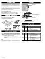
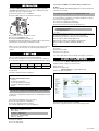
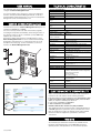
www.eaton.com
Network
Management
Card Minislot
Installation manual
34003905EN/AE
www.eaton.com
INTRODUCTION
OVERVIEW
The Network Management Card is recommended for central UPSs
protecting entire networks or for UPS units backing up critical loads.
With the card installed, the UPS has its own IP address and uses the
local computer capabilities to:
◗ Supply web pages (http or https (SSL)) with information on status
conditions and measurements/settings/alarms,
◗ Integrate an SNMP-based NMS such as HP OpenView, IBM Tivoli
Netview and Computer Associates Unicenter,
◗ Communicate with the protection software installed on the protected
servers (Network Shutdown Module or Netwatch),
◗ Send e-mail and SMS messages,
◗ Control the ON/OFF function of the UPS and the outlets,
◗ Monitor the Environment Sensor (optional, cat. no. 66846).
MAC address
00:20:85:FD:1C:07
ETHERNET 10/100BT port
Service port (Settings/Sensor)
UNPACKING AND CHECKS
Orange LED: RS232 activity
◗ One Network Management Card,
◗ One serial cable for configuration (34003918),
◗ One installation manual (34003905).
Green LED: communication
with the UPS
Orange LED: 10/100M
Green LED: connection +
activity
INDICATIONS
ETHERNET port
LED
ACT
100M
Colour
Green
Orange
CHECK ON UPS VERSION
Status
Description
◗ OFF
◗ ON
◗ Card not connected to network
◗ Card connected to network, but no
◗ Flashing
activity
◗ Port is sending/receiving
◗ OFF
◗ ON
◗ Port operating at 10 Mbits/s
◗ Port operating at 100 Mbits/s
Service port (Settings/Sensor)
Important. Before installing the card, check that the UPS
technical level (NT) is at least equal to that indicated in
the compatibility list (For latest information, check the
website according to your product :
download.mgeops.com for MGE Office Protection
Systems products, www.powerware.com for Powerware
products) .
Note.
◗ If the technical level of the UPS is lower than that indicated in the
compatibility list, contact EATON.
34003905EN/AE
LED
UPS
Data
Colour
Green
Status
◗ OFF
◗ ON
◗ Flashing
Description
◗ Card starting
◗ Communicating with UPS
◗ Normal operation
Communication with UPS is
operational
RS232
Orange
◗ OFF
◗ ON
◗ Configuration menu activated
◗ Normal operation
◗ Flashing
Configuration menu not activated
◗ Communication with Environment
Sensor (option)
INSTALLATION
The Network Management Card can be hot-plugged on all UPSs
compatible with the card. It is not necessary to shutdown the UPS,
disconnect the load or restart the UPS.
◗ Remove the plastic cover of the Minislot.
◗ Note the MAC address of the card before inserting it.
◗ Insert and secure the card with the screws.
◗ Connect the ETHERNET cable.
◗ Check the ETHERNET port indications.
◗ Wait until the UPS Data LED flashes regularly (approx. two minutes),
indicating that card start-up has terminated correctly.
Nota : You can set the parameters via Service port even if the network
is not connected. At connection, the card will restart keeping the
settings.
IP SETTINGS
Once the card has started, proceed as indicated below.
◗ Connect the serial cable to card’s service port and PC’s COM port
◗ Use a terminal emulator such as HyperTerminalTM with these settings
Bits per second
9600
Data bits
8
Stop bits
1
Parity
none
Flow control
none
"Echo typed characters locally" option: disabled
◗ Type admin.
The main configuration menu is displayed:
You can also use NMC Tool software utility to view the card
IP adress
The tool is available at download.mgeops.com. It must be installed on
a network connected PC.
Your network is not equipped with a BOOTP/DHCP server
Manual configuration is required.
To set the network configuration, use terminal emulation (see above)
From the main configuration menu:
◗ Press the 2 key (Network configuration).
◗ Press the 2 key (Modify Network settings).
◗ Follow the instructions and enter the IP parameters:
1 : Read Network settings
2 : Modify Network settings
3 : Set ethernet speed
0 : Exit
For each of the following questions, you can press "Return" to select
the value shown in braces, or you can enter a new value
Should this target obtain IP settings from the network?[N] N
Static IP address [166.99.16.16]?166.99.1.82
Subnet mask IP address [255.255.0.0]? 255.255.255.0
Gateway address IP address [0.0.0.0]? 166.99.17.1
Done
Wait until "Done" is displayed, indicating that the IP parameters have
been saved.
◗ Press the 0 key (Exit).
◗ Press the 1 key (Reset).
◗ Press the 2 key (Restart).
The card restarts with the new IP settings (after approx. one minute).
ACCESS TO SUPERVISION
To check whether the Network Management Card is operational after
installation and IP settings, proceed as follows.
◗ Run a browser
◗ Enter in the address bar:
http://IP address/ (e.g. http://166.99.1.82/)
◗ The home page is displayed
EATON
NETWORK MANAGEMENT CARD
1 : Reset
2 : Network configuration
3 : Set Login Password to Default
4 : Return to Default Configuration
0 : Exit
Your network is equipped with a BOOTP/DHCP server (default)
The card is configured by default with this service enabled. No manual
configuration is required.The IP parameters are automatically collected
by the card.
From the main configuration menu: (see above)
◗ Press the 2 key (Network configuration).
◗ Press the 1 key(Read Network settings).
The settings supplied by the server are displayed:
◗ Set the time by clicking the Time command.
◗ Continue configuration via the sections in the Settings menu.
Network configuration :
MAC address : 00:20:85:FD:1C:07
Mode : DHCP
IP address : 166.99.23.18
Subnet mask : 255.255.248.0
Gateway : 166.99.17
◗ Note the IP address.
◗ Press the 0 key (Exit).
◗ Press the 0 key (Exit).
34003905EN/AE
USER MANUAL
This manual provides all the information required to install and
configure the Network Management Card.
For more information on the supervision, control and configuration
functions offered by the Network Management Card, see the user
manual available at download.mgeops.com or in the Products/Power
Management section at www.powerware.com.
SENSOR CONNECTION (option)
The Environment sensor is a Network Management Card option. It is
available from EATON (cat. no 66846).
The sensor remotely monitors the UPS environment by regularly
measuring the temperature and humidity, and checking the states of
two external contacts. It can also send alarms (e-mail, SNMP trap)
tripped by pre-set thresholds.
Connection is made via the Service port (Settings/Sensor) on the
Network Management Card. The sensor is detected automatically.
Configuration and supervision use a menu that may be accessed
directly from the home page. For more information, see the user
manual of the Network Management Card.
TECHNICAL CHARACTERISTICS
Physical characteristics
Dimensions (W x D x H)
132 x 66 x 42 mm
Weight
70 g
RoHS
100% compatible
Storage
Storage temperature
range
-10°C to 70°C
Ambient conditions
Operating temperature
range
0°C to 40°C
Relative humidity
90% RH max. without condensation
Card performance
Supply voltage
5V ±5%
Supply current (all LEDs
ON and Environment
Sensor connected)
300 mA max.
Functions
Web supervision
5 browsers max. (http),
3 browsers max. (https)
Languages
English, French, German, Italian, Spanish
Alarms
E-mail, SNMP TRAP, Web page
Log
400 measurements or events
Server protection
Up to 100 servers protected
Network
Fast ETHERNET, 10/100 Mbits, auto-negotiation
HTTP 1.1, SNMP V1, NTP, TFTP, SMTP,
BOOTP/DHCP
Identification
User name and password
Security
SSL 3.0, TLS 1.0
Browsers
Microsoft Internet Explorer 6.x or higher
NMS
Enterprise Power Manager (EPM)
Management Pac 2
MIB
MIB II standard - UPS MGE MIB V1.7
Settings (default values)
IP network
BOOTP/DHCP enabled
IP address: 166.99.16.16 (manual configuration)
Subnet mask: 255.255.0.0
Gateway: 0.0.0.0
NTP server: pool.ntp.org
Web-page access control
User name: admin
Password: admin
Service-port menu access
control
Password: admin (not
modifiable)
Date and time
Synchronise with an NTP server (GMT)
Service port
9600 bits/s, 8 bits, 1 bit stop, no parity
ELECTROMAGNETIC COMPATIBILITY
When correctly installed and used in accordance with manufacturer
instructions, the card complies with the following standards:
◗ ITE (Information Technology Equipment) safety: IEC/EN 60950-1 2002
◗ EMC: EN 61000-6-2 (2002), EN 61000-6-3 (2002), IEC/EN 62040-2
(2002). In compliance with European directives:
◗ Low voltage: 73/23/EEC and 93/68/EEC.
◗ EMC: 89/336/EEC and 93/68/EEC.
Federal Communication Commission (FCC) statement
This equipment has been tested and found to comply with the limits for
a Class B digital device, pursuant to part 15 of the FCC rules. These
limits are designed to provide reasonable protection against harmful
interference when the equipment is operated in a commercial
environment.
WEB SITE
The information presented in this manual is also available in other
languages at download.mgeops.com for MGE Office Protection
Systems products, www.powerware.com for Powerware products.
34003905EN/AE