1
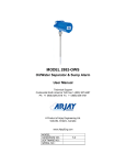
MODEL 9820 PROBE MOUNTED LEVEL SWITCH WITH DIFFERENTIAL User Manual Arjay Engineering Ltd. Oakville (Toronto), Canada, L6H 6C9 Tel . Fax. ++1 (905) 829-2418 ++1 (905) 829-4701 North America 1-800-387-9487 www.arjayeng.com [email protected] 9820 | 9830 High and Low Level Alarm Reliable monitoring of liquids and solids for pump control and alarm Over 30 years of Arjay’s field proven HF capacitance technology has been applied to the 9820 and 9830 level alarms. The probe continuously monitors product levels to control pumps, operate valves, or activate alarms. • capacitance technology does not foul or require cleaning • no moving parts • alarm unit mounts safely away from vessel or can be close coupled to probe 9820 | 9830 The 9820 and 9830 sensing probe monitors the capacitance field around the active probe. As the volume of product increases in the vessel, the probe capacitance changes. This change is used to activate the relay for a high or low alarm. A two point calibration can be set to control a differential between two points along the probe for pump or valve cycling. Features and Benefits Technical Specifications - Control Unit • no moving parts • remote electronics via standard twisted pair with the 9830 • available with Intrinsic Safety Barrier for Hazardous Locations on the 9830 • 9820 can be integral to the probe • high corrosion resistant Teflon and stainless steel wetted parts • capacitance technology responds to all product types • HF capacitance technology does not require routine cleaning • easy calibration and control set-up Operating Temperature Power Input Alarm Relay Standards Enclosure Optional Technical Specifications - Probe Process Temperature Ambient Temperature (probe head) Rating I.S. Approval All calibration, control relays and power wiring is available at the main control unit. This can be safely mounted up to 1 km away from the probe. -20˚C to 50˚C 24 vdc or 110 vac or 220 vac (or 12 vdc on 9820) 5 amp, DPDT, dry UL, CSA 9830 - Type 4X, IP65 9820 - epoxy coated cast aluminum Lights and Buzzer The Model 9820 version provides the electronics mounted directly to the probe for economical and compact installations. -60˚C to 260˚C -20˚C to 50˚C CSA Class 1, Zone 1 and 2, Div 1 and 2, Groups A,B,C,D CSA Class 1, Zone 2, Div 2, Groups A,B,C,D (when ordered with Intrinsic Barrier Option on 9830 version) ABSA-CRN #OF07450.2 The unique PMC circuit design, exclusive to Arjay, immediately converts the sensor signal to a frequency pulse for furtherance to the controller (9830 version). Arjay SS-06 Arjay Engineering Ltd. 2851 Brighton Road Oakville, Ontario Canada L6H 6C9 tel fax N. America email web ++1 905-829-2418 ++1 905-829-4701 1-800-387-9487 [email protected] www.arjayeng.com MODEL DOCUMENT TYPE DOCUMENT FILE NAME REV. 9820 DIFF. LEVEL SWITCH USER MANUAL 9820UM12.DOC 1.2 CREATE DATE REV. DATE PRINT DATE 10/18/2001 2:59:00 PM 12/15/2009 11:57 AM 12/15/2009 11:57:00 AM TABLE OF CONTENTS 1.0 2.0 3.0 4.0 5.0 INSTRUMENT OVERVIEW............................................................................................ 4 1.1 FEATURES ....................................................................................................... 4 1.2 DESCRIPTION .................................................................................................. 4 INSTALLATION .............................................................................................................. 6 2.1 PROBES ............................................................................................................ 6 2.2 PROBE INSTALLATION ................................................................................... 6 2.2 ELECTRICAL INSTALLATION.......................................................................... 8 STARTUP AND CALIBRATION ..................................................................................... 9 3.1 CALIBRATION OVERVIEW .............................................................................. 9 3.2 POWERUP ........................................................................................................ 9 3.3 DIFFERENTIAL LEVEL SWITCH CALIBRATION ............................................ 10 3.4 SINGLE POINT LEVEL SWITCH CALIBRATION............................................. 10 3.5 ALARM SETTINGS ........................................................................................... 11 APPLICATIONS ............................................................................................................. 13 TROUBLESHOOTING ................................................................................................... 15 HARDWARE REV. SOFTWARE REV. 3.0 9820_05 and higher Page 3 of 15 MODEL DOCUMENT TYPE DOCUMENT FILE NAME REV. 9820 DIFF. LEVEL SWITCH USER MANUAL 9820UM12.DOC 1.2 CREATE DATE REV. DATE PRINT DATE 10/18/2001 2:59:00 PM 12/15/2009 11:57 AM 12/15/2009 11:57:00 AM 1.0 INSTRUMENT OVERVIEW 1.1 FEATURES Push-button calibration RF Technology Integral or optional remote level probe Double pole Double Throw (DPDT) 5A relay contacts 0 – 20 second time delay Adjustable sensitivity High and Low (differential) alarm points High or Low relay action No moving parts For use with any Arjay Capacitance probe 1.2 DESCRIPTION The unit senses level using a RF capacitance measurement technique together with microcontroller technology for high resolution measurements. A probe mounted in a vessel forms a capacitor with the vessel wall, or with a concentric shield around the probe for non metallic vessels (ground reference). The capacitance of this arrangement is measured by the 9820 and is used to provide point or differential level switch control. The 9820 RF capacitance measurement technique minimizes the effects of other electrical properties of the probe, vessel and the vessel contents and focuses only on the vessel capacitance. The level switch is available with an integral level probe or optional remote probe which may be located up to 1 km away. High and low alarms are easily set with push-button convenience for differential level applications such as sump pump control. For single point applications, the high and low points are set to the same value. The control relay is always in failsafe mode. The relay action may be set for high or low acting. For horizontal probes, proximity sensors, or Flow Detector sensors, the unit can be calibrated without the level being at the alarm level. MODEL 9820 DIFFERENTIAL LEVEL SWITCH INTEGRAL WITH PROBE OPTIONAL REMOTE PROBE 2 WIRE (SHIELDED) DPDT 5A RELAY INTRINSIC SAFETY BARRIER (OPTIONAL) BLOCK.DSF 115VAC / 220VAC 24VDC (Optional) LARGE VARIETY OF STANDARD CAPACITANCE PROBE STYLES REMOTE CAPACITANCE LEVEL PROBE Figure 1.0 HARDWARE REV. SOFTWARE REV. 3.0 9820_05 and higher Page 4 of 15 MODEL DOCUMENT TYPE DOCUMENT FILE NAME REV. 9820 DIFF. LEVEL SWITCH USER MANUAL 9820UM12.DOC 1.2 CREATE DATE REV. DATE PRINT DATE 10/18/2001 2:59:00 PM 12/15/2009 11:57 AM 12/15/2009 11:57:00 AM OPERATION The unit uses an RF Capacitance measurement technique for high resolution measurements. A probe mounted in a vessel forms a capacitor with the vessel wall (or with a concentric shield around the probe for non metallic vessels). The capacitance of this arrangement is measured by the 9820 to provide point or differential level switch control. USER INTERFACE Instrument status Alarm Status Time delay Relay action Dielectric switch 2 color indicator: Green for normal operation, Red = instrument error, Red/Green (orange) for calibration confirmation. Red indicator: On when not in alarm, Off when in alarm. 0 – 20 seconds. High or Low relay action. For high action, the alarm is set when the capacitance value rises above the high alarm point and is reset when the capacitance drops below the low alarm point. For low action, the alarm is set when the capacitance drops below the low alarm point and is reset when the capacitance rises above the high alarm point. Primarily used in horizontal probe, proximity plate sensor, flow sensor applications to indicate if the probe is at or not at the alarm point at calibration time. PERFORMANCE Resolution The unit measures capacitance in pF. Capacitance to Level translation depends on the tank geometry and the type of material being measured. Capacitance: 0.4% of measured capacitance. Example: at 50pF, the resolution is 0.2pF and at 100pF, the resolution is 0.4pF. For a 5 ft. vertical, concentrically shielded probe in water, this translates to about 0.2” of level. For shorter probe lengths the resolution is higher (0.1” for a 2.5 ft. concentrically shielded probe). PROBE CONNECTION None for integral probe (standard) unit: Factory wired internal to enclosure. For optional remote probe units: 2 wire + shielded cable to probe. RELAY Contacts Failsafe. DPDT 5A (resistive load) /250VAC/30VDC dry contacts. Selectable high or low acting alarm. POWER 115VAC or 220VAC @ 25mA max. 24VDC @ 60mA max. 12VDC @ 75mA max. MECHANICAL SPECIFICATIONS Enclosure Standard: Probe mounted. Dimensions /Weight 3.75” (95mm) diam. x 5.25” (133mm) high / 3lbs. (1.4kg) ENVIRONMENTAL SPECIFICATIONS Operating Temp. -20 to 60°C for Controller only. For remote probe:-40 to 80°C Relative Humidity 90% max. with no condensation. HARDWARE REV. SOFTWARE REV. 3.0 9820_05 and higher Page 5 of 15 MODEL DOCUMENT TYPE DOCUMENT FILE NAME REV. 9820 DIFF. LEVEL SWITCH USER MANUAL 9820UM12.DOC 1.2 CREATE DATE REV. DATE PRINT DATE 10/18/2001 2:59:00 PM 12/15/2009 11:57 AM 12/15/2009 11:57:00 AM 2.0 INSTALLATION NOTE: If any damage to the instrument is found, please notify an Arjay Engineering representative as soon as possible prior to installation. 2.1 PROBES Capacitance probes may be selected from a variety of styles for use with liquids, liquid interfaces, and granular materials. The probe length is customer specified for the height of material desired to be measured. Usually Teflon coated probes are used. 2.2 PROBE INSTALLATION Standard probe entry in to a tank is via a 3/4" NPT opening (standard probes) or 1" NPT opening (heavy duty probes). Flanges and concentric shields are available as options. The entrance configuration may vary depending on the application requirements. TO SCREW IN PROBE (THREADED ENTRY) USE WRENCH ON LOWER HEX. The probe fittings are compression type with Teflon ferrules assembled by applying torque between the two hex sections. The fittings are sealed at the factory to provide a compression seal capable of withstanding high pressures. Once opened they cannot be reassembled without replacing the ferrules. Probe mounting depends on the type of probe used. The following are points to consider: 1. Reference ground: This is VERY IMPORTANT and is typically the metal walls of the tank. For non metallic tanks, a concentrically shielded probe is required in which case the shield provides its own Ground. IMPORTANT: For standard threaded entry and flange entry probes (without concentric shields), make sure the fittings are clean to ensure a GOOD ELECTRICAL CONNECTION BETWEEN THE PROBE HEAD ENCLOSURE AND THE TANK (REFERENCE GND). For horizontally mounted probes, the reference ground is not as important since the changed in capacitance between alarm and no alarm is generally large. It is important that there are no moving objects in the probe vicinity to avoid false alarms. 2. The distance between the probe and the ground reference: This only applies to standard probes without concentric shields. The closer the distance to the tank wall, the greater the sensitivity of measurement; too close and bridging problems may occur. 3. Horizontal probe mounting: A horizontally mounted rod type probe should be mounted so that the lower face of the probe is parallel to and at the level of the desired alarm point. For viscous materials that have a tendency to cling to buildup, the probe should be mounted at a slight angle downwards to allow the material to drain off the probe. 4. Vertical probe mounting: vertically mounted rod type probe should be mounted so that its midpoint is at the desired alarm point for single point applications. This allows a greater variation if the alarm point is later required to be changed. The alarm point may be calibrated anywhere along the length of the probe. 5. Location: Avoid installing rod type probes in nozzles or recesses where material can accumulate false readings. 6. The measurement accuracy is affected by the temperature change of the material in the tank. The amount of measurement error depends on the material. If the temperature change is HARDWARE REV. SOFTWARE REV. 3.0 9820_05 and higher Page 6 of 15 MODEL DOCUMENT TYPE DOCUMENT FILE NAME REV. 9820 DIFF. LEVEL SWITCH USER MANUAL 9820UM12.DOC 1.2 CREATE DATE REV. DATE PRINT DATE 10/18/2001 2:59:00 PM 12/15/2009 11:57 AM 12/15/2009 11:57:00 AM excessive, temperature correction will be required. Contact the Arjay representative for more information. 7. Agitators or moving objects in the tank: Moving objects in the tank close to the probe such as agitator blades, moving baffles etc. appear as moving ground references to a capacitance probe and will cause measurement errors. In applications where these objects are present, a concentrically shielded probe must be used. CAUTION: INSTALL PROBE WITH CARE: DAMAGE TO TEFLON SHEATH WILL CAUSE MEASUREMENT ERRORS. THREADED ENTRY FLANGED ENTRY CONCENTRIC SHIELD ENTRY Use wrench on Lower Hex ONLY 2" Entry Typical 1- For threaded and flanged entry types, measurement sensitivity is increased by reducing the probe to wall distance. 2- There should be good electrical conductivity between the tank wall and the transmitter enclosure. (For probes with a concentric shield this is not important). INSTALL PROBE WITH CARE: IF TEFLON COATING IS DAMAGED, THE PROBE WILL NOT WORK PROBE.DSF PROBE INSTALLATION Figure 2.0 HARDWARE REV. SOFTWARE REV. 3.0 9820_05 and higher Page 7 of 15 MODEL DOCUMENT TYPE DOCUMENT FILE NAME REV. 9820 DIFF. LEVEL SWITCH USER MANUAL 9820UM12.DOC 1.2 CREATE DATE REV. DATE PRINT DATE 10/18/2001 2:59:00 PM 12/15/2009 11:57 AM 12/15/2009 11:57:00 AM 2.2 ELECTRICAL INSTALLATION ALARM STATUS Single DPDT relay with dry contacts rated at 5A @ 250VAC or 30VDC for resistive loads. DPDT RELAY NO C CALIBRATE NC DIELECTRIC LOW HIGH NO C SENSITIVITY Terminals marked + and - are for DC power units. POWER NC ALARM DELAY GND L2 (-) RELAY L1 (+) LOW HIGH PROBE IN + MODEL 9820 DIFFERENTIAL LEVEL SWITCH PROBE WIRING (Due to possible probe static build up during shipping the probe wire has been left disconnected. Please ground probe wire momentarily before reconnecting) POWER: 115VAC power is standard. For 220VAC, 24VDC or 12VDC units power must be stated at time of order. For DC power units, the L1 terminal is to be connected to the positive supply, and the L2 terminal for the negative supply. ELECT.DSF ELECTRICAL INSTALLATION Figure 2.2 NOTE: 115VAC power is standard. Other power supply voltages are supported (220VAC. 24VDC, 12VDC) and must be specified at time of order. APPLYING POWER THAN THAT MEANT FOR THE UNIT MAY CAUSE DAMAGE AND OR INJURY. HARDWARE REV. SOFTWARE REV. 3.0 9820_05 and higher Page 8 of 15 MODEL DOCUMENT TYPE DOCUMENT FILE NAME REV. 9820 DIFF. LEVEL SWITCH USER MANUAL 9820UM12.DOC 1.2 CREATE DATE REV. DATE PRINT DATE 10/18/2001 2:59:00 PM 12/15/2009 11:57 AM 12/15/2009 11:57:00 AM 3.0 STARTUP AND CALIBRATION ALARM STATUS Calibrate Pushbutton CALIBRATE DIELECTRIC HIGH 9 0 1 9 0 1 8 7 ALARM DELAY 6 5 4 2 3 8 7 SENSITIVITY 6 5 4 2 3 LOW Alarm delay: 0 - 20sec. Each switch inc. = 2sec except 6=15 and 7=20. 8&9 not used = 0sec. Sets alarm direction: above or below alarmpoint RELAY LOW For horizontal, proximity and Dry Pump (flow) probes: Allow calibration without level being at alarm point. HIGH PROBE IN + MODEL 9820 DIFFERENTIAL LEVEL SWITCH USERINT.DSF USER INTERFACE Figure 3.0 3.1 CALIBRATION OVERVIEW Calibration and switch settings are determined by the type of probe and application. There are 2 main application types: 1. Differential level control. This application requires the use of a vertical probe. 2. Single point level switch using a vertical probe, horizontal probe, proximity sensor, or Dry Pump (Flow detection) probe. 3.2 POWERUP After the unit has been installed as per the installation procedure in section 2, power up the unit. The Status indicator should be Green. The red Alarm indicator may be on or off and is not valid until a successful calibration has been done. If the Status indicator is red refer to the troubleshooting procedure in section 5.0 for details. HARDWARE REV. SOFTWARE REV. 3.0 9820_05 and higher Page 9 of 15 MODEL DOCUMENT TYPE DOCUMENT FILE NAME REV. 9820 DIFF. LEVEL SWITCH USER MANUAL 9820UM12.DOC 1.2 CREATE DATE REV. DATE PRINT DATE 10/18/2001 2:59:00 PM 12/15/2009 11:57 AM 12/15/2009 11:57:00 AM 3.3 DIFFERENTIAL LEVEL SWITCH CALIBRATION This application requires a vertically mounted probe. Along the vertical length of the probe, the high and low alarm points will be calibrated. For this application, the Dielectric and Sensitivity switch settings are not important. They should be set to Low and 0 respectively. 1. Bring the level to the first alarm point. This can be the high or low alarm level. After calibration, the 9820 automatically assigns the high alarm point to the point with the higher measured capacitance. 2. Press the Calibrate push-button until the Status indicator glows orange. The Status indicator then starts flashing green indicating that the first alarm point has been stored. 3. Bring the level to the second alarm point. Press the Calibrate push-button until the Status indicator glows orange. 4. This completes the calibration procedure. Please refer to section 3.6 for setting the time delay and relay action. Also refer to the Applications section for examples. 3.4 SINGLE POINT LEVEL SWITCH CALIBRATION The 9820 is a differential level switch so for single alarm points, the high and low alarm points must be calibrated for the same level. For horizontal probes, proximity sensors, and Dry Pump monitors (Flow switch) application, the 9820 allows calibration without requiring the level to be at the alarm point. This is done using the Dielectric and Sensitivity switch settings. NOTE: FOR VERTICAL PROBES, CALIBRATION SHOULD BE DONE WITH THE LEVEL AT THE DESIRED ALARM POINT. The Dielectric switch value is set to High if at calibration time, the level of material in the vessel or pipe is above the alarm point i.e. for horizontal probes, the probe is immersed. After calibration, the actual alarm point is internally set to the captured capacitance minus the Sensitivity switch value. For example, if the capacitance at calibration was 100pF and the Dielectric switch was set to High then the actual alarm point is internally set to 100pF - the Sensitivity switch value (0-7pF only). So if the sensitivity switch is set to 5, the actual alarm point is 95pF. Increasing the Sensitivity switch setting thus increases the amount of level change required to switch from the alarm state at calibration. Conversely, the Dielectric switch is set to Low if the level is below the alarm point during calibration. After calibration, the actual alarm point is internally set to the captured capacitance plus the Sensitivity switch value. For example, if the capacitance at calibration was 100pf and the Dielectric switch was set to Low then the actual alarm point is internally set to 100pF + the Sensitivity switch value. So if the sensitivity switch is set to 5, the actual alarm point is 105pF. Increasing the Sensitivity switch setting thus increases the amount of level change required to switch from the alarm state at calibration. NOTES: FOR VERTICAL PROBES, IT IS RECOMMENDED THAT CALIBRATION BE DONE WITH THE LEVEL AT THE DESIRED ALARM POINT. THE DIELECTRIC AND SENSITIVITY SWITCHES ARE NOT IMPORTANT AND MAY BE SET TO LOW AND 1 RESPECTIVELY. THE DIELECTRIC SWITCH SETTING IS ONLY CAPTURED AT CALIBRATION TIME. IT’S SETTING AFTER CALIBRATION DOES NOT AFFECT OPERATION. HARDWARE REV. SOFTWARE REV. 3.0 9820_05 and higher Page 10 of 15 MODEL DOCUMENT TYPE DOCUMENT FILE NAME REV. 9820 DIFF. LEVEL SWITCH USER MANUAL 9820UM12.DOC 1.2 CREATE DATE REV. DATE PRINT DATE 10/18/2001 2:59:00 PM 12/15/2009 11:57 AM 12/15/2009 11:57:00 AM THE SENSITIVITY SWITCH VALUE IS READ CONTINUOUSLY. IT’S SETTING AFTER CALIBRATION DOES AFFECT OPERATION (THE SENSITIVITY VALUE IS ADDED TO OR SUBTRACTED FROM THE CAPACITANCE VALUE CAPTURED AT CALIBRATION TO PRODUCE THE NEW ALARM POINT. 1. For vertical capacitance probes, bring the level to the desired alarm point. 2. For horizontal probes, proximity sensors, or Dry Pump monitors, determine if the level is above or below the desired alarm point. If it is below, set the Dielectric switch to Low. Conversely, if it is higher than the desired alarm level, set the Dielectric switch to High. 3. Press the Calibrate push-button until the Status indicator glows orange. The Status indicator then starts flashing green indicating that the first alarm point has been stored. 4. Press the Calibrate push-button again until the Status indicator glows orange. The second alarm point is assigned the same level value as the first resulting in a single alarm point. 5. This completes the calibration procedure. The Status indicator should be a steady green. 6. Set the Sensitivity switch to some value other than 0pF. The amount depends on the application. The value sets the amount (in pF) the measured capacitance has to change from the current value to switch alarm states. NOTE: THE SENSITIVITY SWITCH RANGE IS 0 – 7pF. SWITCH SETTINGS 8 AND 9 ARE EQUIVALENT TO 0pF. A sensitivity value of 1 is most commonly used. Please refer to section 3.5 below for setting the time delay and relay action. 3.5 ALARM SETTINGS The relay is always in the failsafe condition: i.e. in alarm, the relay is off and vice versa. NOTE: FOR ALL APPLICATIONS WHERE THE 9820 IS CONTROLLING PUMP ACTION, THE NORMALLY OPEN (NO) CONTACTS MUST BE USED TO ENSURE THE PUMP IS SHUT OFF IN THE EVENT OF A POWER FAILURE TO THE 9820. THE RELAY ACTION SWITCH MAY BE USED TO GIVE THE CORRECT CONTACT CONDITIONS. There are 3 alarm settings: 1. RELAY ACTION. This is set via the Relay Action switch. When set to High, the failsafe relay is de-energized and alarm indicator is off when the level rises above the High Alarm point for at least the alarm delay period. The relay is energized and the Alarm indicator is on (with no time delay) when the level falls below the Low Alarm point. Conversely, when the Relay Action switch is set to Low, the failsafe relay is de-energized and alarm indicator is off when the level drops below the Low Alarm point for at least the alarm delay period. The relay is energized and the alarm indicator is on (with no time delay) when the level rises above the High Alarm point Note: for Single point alarms, the High and Low Alarm points are at the same level. This switch is also used to switch contact conditions. For example, for pump control applications where the pump must be shut off in the event of a power failure to the 9820, the Normally Open contacts must be used. The state of the relay contacts during an alarm and power failure is changed using the Relay Action switch. 2. ALARM TIME DELAY. This is set via the Time Delay switch. An alarm based on the Relay Action switch must be present for at least the time delay value for the relay to switch to the alarm state. There is no delay when switching off the alarm. The delay range is 0 – 20 seconds. HARDWARE REV. SOFTWARE REV. 3.0 9820_05 and higher Page 11 of 15 MODEL DOCUMENT TYPE DOCUMENT FILE NAME REV. 9820 DIFF. LEVEL SWITCH USER MANUAL 9820UM12.DOC 1.2 CREATE DATE REV. DATE PRINT DATE 10/18/2001 2:59:00 PM 12/15/2009 11:57 AM 12/15/2009 11:57:00 AM DELAY SWITCH SETTING TIME DELAY 0 0 seconds 1 2 seconds 2 4 seconds 3 6 seconds 4 8 seconds 5 10 seconds 6 15 seconds 7 20 seconds 8&9 Not used and act as 0 seconds. The delay is always to enter the alarm condition (failsafe relay de-energized, alarm indicator off). If the Relay Action switch is set to High, the delay is applied to de-energize the failsafe relay as the level rises above the High Alarm Point. If the Relay Action switch is set to Low, the delay is applied to de-energize the failsafe relay as the level drops below the Low Alarm point. 3. SENSITIVITY SETTING. This has already been described in section 3.4. It is primarily used for horizontal probes, proximity sensors, or Dry Pump monitors. The switch setting is used to add to or subtract from the calibrated level value to add more immunity from noise and also to allow calibration to be performed without the level being at the desired alarm point. See the applications section for more details. Typical applications use a sensitivity setting of 1 THIS COMPLETES THE SETUP AND CALIBRATION PROCEDURE FOR THE 9820 LEVEL SWITCH HARDWARE REV. SOFTWARE REV. 3.0 9820_05 and higher Page 12 of 15 MODEL DOCUMENT TYPE DOCUMENT FILE NAME REV. 9820 DIFF. LEVEL SWITCH USER MANUAL 9820UM12.DOC 1.2 CREATE DATE REV. DATE PRINT DATE 10/18/2001 2:59:00 PM 12/15/2009 11:57 AM 12/15/2009 11:57:00 AM 4.0 APPLICATIONS SETTINGS: Relay Action: LOW PUMP CONTROL Dielectric & Sensitivity Switch Settings not important. PROCESS IN HIGH ALARM POINT HIGH ALARM POINT LOW ALARM POINT LOW ALARM POINT PUMP ON PUMP OFF PROCESS OUT DIFFERENTIAL LEVEL SWITCH APPLICATION: PUMPING OUT PUMP CONTROL SETTINGS: Relay Action: HIGH Dielectric & Sensitivity Switch Settings not important. PROCESS IN APPS.DSF HIGH ALARM POINT HIGH ALARM POINT LOW ALARM POINT LOW ALARM POINT PUMP ON PUMP OFF PROCESS OUT APPS.DSF DIFFERENTIAL LEVEL SWITCH APPLICATION: PUMPING IN HARDWARE REV. SOFTWARE REV. 3.0 9820_05 and higher Page 13 of 15 MODEL DOCUMENT TYPE DOCUMENT FILE NAME REV. 9820 DIFF. LEVEL SWITCH USER MANUAL 9820UM12.DOC 1.2 CREATE DATE REV. DATE PRINT DATE 10/18/2001 2:59:00 PM 12/15/2009 11:57 AM 12/15/2009 11:57:00 AM CALIBRATION DONE AT ALARM POINT DIELECTRIC SWITCH: HIGH SENSITIVITY SWITCH depresses alarm point i.e. level has to fall by a greater amount to switch from the current alarm state as the Sensitivity switch value is increased. CALIBRATION DONE BELOW ALARM POINT DIELECTRIC SWITCH: LOW SENSITIVITY SWITCH elevates alarm point i.e. level has to rise by a greater amount to switch from the current alarm state as the Sensitivity switch value is increased.. ALARM POINT ALARM POINT RELAY ACTION:HIGH Relay de-energized Delay to de-energize RELAY ACTION:LOW Relay de-energized Delay to de-energize APPS.DSF CALIBRATION OPTIONS / RELAY ACTION FOR POINT LEVEL ALARM NOTES ON HORIZONTAL PROBES: If the probe is not shielded, the measured capacitance will slowly rise as the level approaches the probe based on the material in the tank, the tank shape and probe length. Therefore if the calibration is done while the level is below the probe using the Dielectric switch set to low the 9820 may trigger an alarm before the level actually reaches the probe. This discrepancy may be reduced by setting the sensitivity switch to its max. value of 7. The application should be verified to ensure the resulting alarm point is at the desired level. HARDWARE REV. SOFTWARE REV. 3.0 9820_05 and higher Page 14 of 15 MODEL DOCUMENT TYPE DOCUMENT FILE NAME REV. 9820 DIFF. LEVEL SWITCH USER MANUAL 9820UM12.DOC 1.2 CREATE DATE REV. DATE PRINT DATE 10/18/2001 2:59:00 PM 12/15/2009 11:57 AM 12/15/2009 11:57:00 AM 5.0 TROUBLESHOOTING CONDITION 1. No indicators on at powerup 2. Status indicator is RED DO THIS Check power to unit. Make sure power applied is as specified for the unit. If power is ok, check the fuse. If fuse is blown call an Arjay representative to analyze why the fuse in blown. This indicates that the probe signal is either weak, unstable, out of legal range, or is not present. Unplug the probe connector to the 9820. The probe wiring is internal to the enclosure on standard units. The probe wire comes up from the bottom of the enclosure and plugs to the 9820 circuit board. If status indicator is green after unplugging the probe then check the probe as follows: With the probe connector unplugged, measure the resistance with a digital resistance meter between the minus of the probe (as marked on the front plate) and the enclosure case. For a good probe, the resistance should read open (OL on the meter display). Any other value indicates a bad probe. In either case, call an Arjay representative or Arjay Technical support. HARDWARE REV. SOFTWARE REV. 3.0 9820_05 and higher Page 15 of 15