1
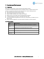
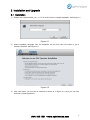
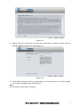
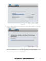
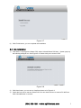
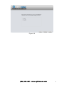
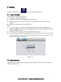
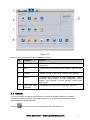
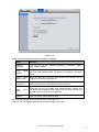
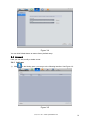
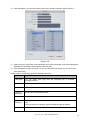
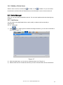
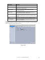
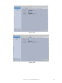
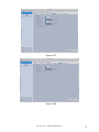
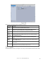
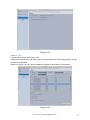
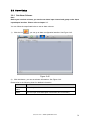
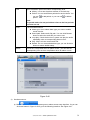
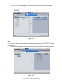
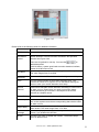
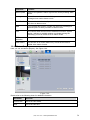
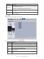
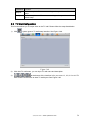
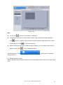
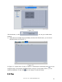
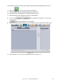
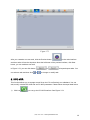
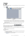
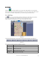
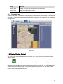
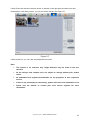
Smart Professional Surveillance System User’s Manual
Optiview Inc.
5211 Fairmont Street
Jacksonville, FL 32207
Version 1.0.0
(904) 805-1581 • www.optiviewusa.com
Table of Contents
1
OVERVIEW AND ENVIRONMENT..................................................................... 1
1.1
Overview ................................................................................................................................................. 1
1.2
Environment ........................................................................................................................................... 1
2
INSTALLATION AND UPGRADE ....................................................................... 2
2.1
Installation............................................................................................................................................... 2
2.2
Un-installation ........................................................................................................................................ 5
3
SETTING ............................................................................................................ 7
3.1
Login Interface ....................................................................................................................................... 7
3.2
Main Interface ........................................................................................................................................ 7
3.3
General.................................................................................................................................................... 8
3.4
Account ................................................................................................................................................. 10
3.4.1
Add user ........................................................................................................................................... 10
3.4.2
Modify or Delete Users................................................................................................................... 12
3.5
Device Manager................................................................................................................................... 12
3.5.1
Add Device....................................................................................................................................... 12
3.5.1.1
Auto add ................................................................................................................................. 12
3.5.1.2
Manual Add ............................................................................................................................ 13
3.5.1.3
Add/Modify Device ................................................................................................................ 14
3.5.2
Group Manager ............................................................................................................................... 14
3.5.3
Parameter Setup............................................................................................................................. 16
3.5.3.1
Network................................................................................................................................... 17
3.5.3.2
Event ....................................................................................................................................... 23
(904) 805-1581 • www.optiviewusa.com
i
3.5.3.3
Storage ................................................................................................................................... 28
3.5.3.4
System .................................................................................................................................... 29
3.5.3.5
Info........................................................................................................................................... 36
3.6
Alarm Setup.......................................................................................................................................... 38
3.6.1
Set Alarm Scheme.......................................................................................................................... 38
3.6.2
Alarm Activation Video ................................................................................................................... 41
3.6.3
Enable/Disable/Export Scheme .................................................................................................... 43
3.7
Alarm Input/Output .............................................................................................................................. 43
3.7.1
Alarm Input....................................................................................................................................... 43
3.7.2
Alarm Output.................................................................................................................................... 45
3.8
Signal Sources ..................................................................................................................................... 45
3.8.1
Audio/Video ..................................................................................................................................... 46
3.8.1.1
Audi/Video .............................................................................................................................. 46
3.8.1.2
Snapshot................................................................................................................................. 47
3.8.1.3
Video Overlay ........................................................................................................................ 48
3.8.2
Record .............................................................................................................................................. 49
3.8.2.1
Schedule record/Schedule snapshot.................................................................................. 49
3.8.2.2
Record control........................................................................................................................ 50
3.8.3
Detect ............................................................................................................................................... 51
3.8.4
Picture Property .............................................................................................................................. 54
3.8.5
PTZ ................................................................................................................................................... 55
3.9
TV Wall Configuration ......................................................................................................................... 56
3.10
Tour ....................................................................................................................................................... 58
3.11
PC-NVR ................................................................................................................................................ 60
4
BASIC OPERATION ......................................................................................... 65
4.1
Preview.................................................................................................................................................. 65
4.1.1
Real-time Preview........................................................................................................................... 65
4.1.2
Record .............................................................................................................................................. 67
4.1.3
Snapshot .......................................................................................................................................... 67
4.1.4
PTZ ................................................................................................................................................... 68
4.1.4.1
Preset...................................................................................................................................... 69
4.1.4.2
Tour ......................................................................................................................................... 69
(904) 805-1581 • www.optiviewusa.com
ii
4.2
Playback................................................................................................................................................ 71
4.2.1
Playback Record............................................................................................................................. 72
4.2.2
Record List....................................................................................................................................... 73
4.3
Alarm Manager..................................................................................................................................... 75
4.4
Alarm Activation ................................................................................................................................... 76
5
EXTENSION ..................................................................................................... 78
5.1
TV Wall.................................................................................................................................................. 78
5.2
E-map .................................................................................................................................................... 79
5.2.1
Edit E-map ....................................................................................................................................... 79
5.2.2
Preview E-map ................................................................................................................................ 80
5.3
Device Display Control ....................................................................................................................... 80
5.4
Local Data............................................................................................................................................. 81
(904) 805-1581 • www.optiviewusa.com
iii
Welcome
Thank you for using our Smart Professional Surveillance System (Smart PSS)!
This user’s manual is designed to be a reference tool for operation of your system.
Here you can find detailed operation information about Smart PSS.
(904) 805-1581 • www.optiviewusa.com
iv
1 Overview and Environment
1.1 Overview
Smart PSS is an abbreviation for Smart Professional Surveillance System.
It is software to manage small quantity security surveillance devices. It releases with the device
and does not support the products from other manufacturers. It has the following features:
z View real-time video of several camera channels.
z View the playback video files from various cameras.
z Support multiple scheduled arms to realize auto PC guard.
z Support e-map; you can clearly view and manage all device locations.
z TV wall plan setup and can output TV wall video at the same time.
z It can create individual configuration files for each user, which allows you maintain your own
habit and style.
z Support extension applications, can send out alarm information to external programs.
1.2 Environment
Item
Requirements
OS
Windows 2000/Windows XP/Windows 2003/Window Vista/Win7.
CPU
2.4GHz or higher.
Display card
Independent car and support directX 8.0c or higher.
Memory
1GB or higher.
Displayer
Resolution
1024×768 or higher.
(904) 805-1581 • www.optiviewusa.com
1
2 Installation and Upgrade
2.1 Installation
1)
Double click “OptiviewVMS_ver.1.11.1.R.9.10.2014.B.exe” to begin installation. See Figure 2-1.
Figure 2-1
2)
Select installation language from the dropdown list and then click OK button to go to
Welcome interface. See Figure 2-2.
Figure 2-2
3)
Click next button, you can see an interface is shown as in Figure 2-3. Here you can view
End user License Agreement.
(904) 805-1581 • www.optiviewusa.com
2
Figure 2-3
4)
Please check the Accept item and then click Next button to continue. System pops up
module installation dialogue box. See Figure 2-4.
Figure 2-4
5)
Check Smart PSS item and then click Next button, you can see there is an interface asking
you to specify installation path. See Figure 2-5.
Note
You can check PC-NVR item if necessary.
(904) 805-1581 • www.optiviewusa.com
3
Figure 2-5
6)
After you select installation path click Next button, system begins installation. The interface
is shown as in Figure 2-6.
Figure 2-6
7)
During the installation process, you can click Cancel button to exit. After installation, you can
see an interface is shown as below. See Figure 2-7.
(904) 805-1581 • www.optiviewusa.com
4
Figure 2-7
8)
Click Finish button, you can complete the installation.
2.2 Un-installation
1)
From Start -> All programs->Smart PSS, select Uninstall Smart PSS item. System pops up
the following dialogue box. See Figure 2-8. Please click yes to remove PSS.
Figure 2-8
2)
3)
Click Next button, you can see an interface shown as in Figure 2-9.
Check the box here to remove Smart PSS. You can check the box to remove PC-NVR too.
Click Uninstall button to remove.
(904) 805-1581 • www.optiviewusa.com
5
Figure 2-9
(904) 805-1581 • www.optiviewusa.com
6
3 Setting
Double click Smart PSS icon
, you can go to the login interface.
3.1 Login Interface
Login interface is shown as in Figure 3-1.
z User name: Input the user account
z Password: Please input corresponding password to log in.
z OK: Click this button, system can verify the account and then enter the software main
interface.
z Cancel: Click this button to exit login interface.
Note:
z If it is your first time to run the Smart PSS program, default user name is admin and its
password is admin too. Admin is a super administrator and can not be removed. It can add,
modify or delete other user.
z For security reason, please modify your password after first log in.
z You can memory your password, so that when you can log in the next time, you do not need
to input user name and password. Please note this function is for your convenient only. Do
not enable this function in public PC.
Figure 3-1
3.2 Main Interface
Click Login button, system begins verifying user name and password and then go to the main
interface. See Figure 3-2.
(904) 805-1581 • www.optiviewusa.com
7
Figure 3-2
Please refer to the following sheet for detailed information.
SN
Parameter
Function
1
Menu
Here you can view main page icons and current open
function icon.
2
Basic
It includes preview, playback, alarm manager, alarm link and
etc.
3
Extension
It includes TV wall, e-map, device display control and etc.
4
Setting
It includes basic configuration, alarm configuration, alarm
input/output, signal source, TV wall configuration, device
manager, user manager, PC-NVR manager, monitor task
setup and etc.
5
Smart PSS basic
information
It is to display current time, user information, login time.
3.3 General
If it is your first time to login the Smart PSS, you need to set system parameter. It includes
network performance, log save time, login Smart PSS or not, picture and record saved path.
Please follow the steps listed below.
Click the
button; you can go to the general interface. See Figure 3-3.
(904) 805-1581 • www.optiviewusa.com
8
Figure 3-3
Please refer to the following sheet for detailed information.
Item
Function
Network
function
It is for you to set network function. It includes: “WAN”,
“10M”,’100M’,”1000M”.
Log
period
save
Here you can set log save time. System automatically overwrites old
files once it reaches the period you set here. It includes; 1/2/3/4/5/6month.
Auto
login
Smart PSS
Check the box here, you can login Smart PSS directly without
inputting user name and password.
Auto
login
Windows
Check the box here and then input user name and password, you
can go to the Windows OS after the computer restart.
Auto
time
Check the box here to enable time synchronization function and
then input synchronization time. Smart PSS can auto synchronize
time with the PC at the time you specified.
Default
sync
Click it to restore system default setup.
File configuration interface is shown as below. See Figure 3-4.
Here you can set snapshot picture and record file default save path.
(904) 805-1581 • www.optiviewusa.com
9
Figure 3-4
You can click Default button to restore factory default setup.
3.4 Account
Here you can add, modify or delete a user.
3.4.1 Add user
1)
Click
in the Setting pane, you can go to the following interface. See Figure 3-5.
Figure 3-5
(904) 805-1581 • www.optiviewusa.com
10
2)
Click Add button, you can see system pops up the following interface. See Figure 3-6.
Figure 3-6
3)
Select user type, input user name, password and confirm password. Input some description
information if necessary. Select rights for the new user.
4) Click add button to add a new user. Or you can click Add more button if you want to add
more new users.
Please refer to the following sheet for detailed information.
Item
Function
User type
You can select user type from the dropdown list. It includes:
manager/operator.
User name
Please input user name here.
Password
Please set user password.
Confirm
password
Please input new password again.
Details
You can input some description information here if necessary,.
User
authority
Here you can check the box to select corresponding rights for current
user.
If the new user is a manager, system checks all rights by default.
Add more
Check the box here if you want to add more users.
(904) 805-1581 • www.optiviewusa.com
11
3.4.2 Modify or Delete Users
Select a user in the list, and then click
to modify, or click
to delete it. Or you can select
several users and then click the Delete button at the left bottom corner to remove them all.
3.5 Device Manager
Here you can add, modify and delete a device. You can also implement device channel group
function.
3.5.1 Add Device
You can refer to the steps listed below to add, modify or delete a device manually or
automatically.
3.5.1.1 Auto add
1)
Click
icon, system goes to the device manager interface; you can see an interface is
shown as in Figure 3-7.
Figure 3-7
2)
3)
Click Auto add button, you can see an interface shown as in Figure 3-8.
Please check the box to select the devices you want to add and then click the Add button.
(904) 805-1581 • www.optiviewusa.com
12
Figure 3-8
3.5.1.2 Manual Add
Click Manual Add button, the interface is shown as in Figure 3-9. Please input the corresponding
information and then click Add button.
Figure 3-9
Please refer to the following sheet for detailed information.
(904) 805-1581 • www.optiviewusa.com
13
Item
Function
Device name
Please input a device name here.
Group name
It defined by the device name.
Type
Select a device type from the dropdown list.。
IP/Domain
name
Device IP address or domain name.
Port
Device IP port.
User name
The user name you login the device.
Password
The password you login the device.
Getting info
It is to get the online device information automatically.
Device
model
Device model. Read-only.
Device SN
Device SN. Read-only.
Video input
Device video input channel amount.
Video output
Device video output channel amount.
Alarm input
Device alarm input amount.
Alarm output
Device alarm output amount.
Continuous
add
Click it to add more devices.
Create
Group
Add current device to group manager interface as one new group.
3.5.1.3 Add/Modify Device
Select a device in the list, and then click
to modify, or click
to delete it. Or you can select
several devices and then click the Delete button at the left bottom corner to remove them all.
3.5.2 Group Manager
Note
z For a device or a channel that is not included in the group management mode, you
can not view it on the device list of the Preview interface.
z You do not need to implement group management if you have checked the box
on Figure 3-9 when you add a new device.
(904) 805-1581 • www.optiviewusa.com
14
After you add devices, you can set channel group to manage it.
1)
Right click the
at the top
right pane on Figure 3-7, you can go to the following interface. See Figure 3-10.
Figure 3-10
2)
Click the New group button at the right top corner, you can create new group.
Note
z
z
You can double click group name to change its name. Or you can right click a group
name to rename or delete it.
to delete it.
You can select a group and then click the button
3)
On the Device list on the right pane, you can select a device. You can view the
corresponding channel name on the near pane.
4)
Select corresponding channels and then click
5)
group you created here. See Figure 3-11. Double click a channel; you can change its name.
Click Finish button to complete the setup.
, you can add channels to the new
(904) 805-1581 • www.optiviewusa.com
15
Figure 3-11
Tips
You can user Ctrl+left click mouse to select several channels at the same time. Or you can user
Ctril+A to select all channels.
3.5.3 Parameter Setup
After you added a new device, you can select it and then click button
at the operation column
on the device manager interface. It is for you to set device parameters. See Figure 3-12.
Figure 3-12
(904) 805-1581 • www.optiviewusa.com
16
Tips
) and click the
You can go to the signal sources interface (
at the left bottom to go to the device setup interface.
button
3.5.3.1 Network
3.5.3.1.1
TCP/IP
Here you can set corresponding parameter when you are using TCP/IP connection. See Figure
3-13.
Figure 3-13
3.5.3.1.2
Connect
Here you can set max login account amount, TCP port, UDP port, HTTP port, RTSP port and etc.
See Figure 3-14.
(904) 805-1581 • www.optiviewusa.com
17
Figure 3-14
3.5.3.1.3
PPPoE
PPPoE interface is shown as below. See Figure 3-15.
Input “PPPoE name” and “PPPoE password” you get from your ISP (Internet service provider).
Click OK button, you need to restart to activate your configuration.
After rebooting, device will connect to internet automatically. The IP in the PPPoE is the device
dynamic value. You can access this IP to visit the device.
Figure 3-15
(904) 805-1581 • www.optiviewusa.com
18
3.5.3.1.4
DDNS
DDNS setup interface is shown as in Figure 3-16.
You need a PC of fixed IP in the internet and there is the DDNS software running in this PC. In
other words, this PC is a DNS (domain name server).
In network DDNS, please select DDNS type and highlight enable item. Them please input your
PPPoE name you get from you IPS and server IP (PC with DDNS ) . Click OK button and then
reboot system.
Click Ok button, system prompts for rebooting to get all setup activated.
After rebooting, open IE and input as below:
http://(DDNS server IP)/(virtual directory name)/webtest.htm
Figure 3-16
Please refer to the following sheet for detailed information.
Parameter
Function
Server Type
You can select DDNS protocol from the dropdown list and then
enable DDNS function.
Server IP
DDNS server IP address
Server Port
DDNS server port.
Domain Name
Your self-defined domain name.
User
The user name you input to log in the server.
Password
The password you input to log in the server.
Update interval
Device sends out alive signal to the server regularly.
You can set interval value between the device and DDNS server
here.
3.5.3.1.5
IP Filter
IP filter interface is shown as in Figure 3-17. You can add IP in the following list.
(904) 805-1581 • www.optiviewusa.com
19
After you enabled whitelist function, only the IP listed below can access current device.
If you enable blacklist function, the following listed IP addresses can not access current device.
Figure 3-17
3.5.3.1.6
SMTP (Email)
The SMTP interface is shown as in Figure 3-18. Here you can set email receiver, encryption
mode, send out interval and etc.
Figure 3-18
(904) 805-1581 • www.optiviewusa.com
20
Please refer to the following sheet for detailed information.
Parameter
Function
Enable
Please check the box here to enable email function.
SMTP Server
Input server address and then enable this function.
Port
Default value is 25. You can modify it if necessary.
Anonymity
For the server supports the anonymity function. You can auto
login anonymously. You do not need to input the user name.
password and the sender information.
User Name
The user name of the sender email account.
Password
The password of sender email account.
Sender
Sender email address.
Encryption mode
System supports SSL/NONE/TLS.
Subject
Input email subject here.
Attachment
System can send out the email of the snapshot picture once
you check the box here.
Receiver
Input receiver email address here. Max three addresses.
Interval
The send interval ranges from 0 to 3600 seconds. 0 means
there is no interval.
Please note system will not send out the email immediately
when the alarm occurs. When the alarm, motion detection or
the abnormity event activates the email, system sends out the
email according to the interval you specified here. This
function is very useful when there are too many emails
activated by the abnormity events, which may result in heavy
load for the email server.
Please check the box here to enable this function.
Health mail
enable
Health mail
interval
Test
3.5.3.1.7
This function allows the system to send out the test email to
check the connection is OK or not.
Please check the box to enable this function and then set the
corresponding interval.
System can send out the email regularly as you set here.
The system will automatically sent out a email once to test the
connection is OK or not .Before the email test, please save
the email setup information.
Multicast
The multicast interface is shown as in Figure 3-19.
Multicast is a transmission mode of data packet. When there is multiple-host to receive the same
data packet, multiple-cast is the best option to reduce the broad width and the CPU load. The
source host can just send out one data to transit. This function also depends on the relationship
of the group member and group of the outer.
(904) 805-1581 • www.optiviewusa.com
21
Figure 3-19
3.5.3.1.8
Alarm Server
The alarm centre interface is shown as below. See Figure 3-20.
This interface is reserved for you to develop. System can upload alarm signal to the alarm centre
when local alarm occurs.
Before you use alarm centre, please set server IP, port and etc. When an alarm occurs, system
can send out data as the protocol defined, so the client-end can get the data.
Figure 3-20
(904) 805-1581 • www.optiviewusa.com
22
3.5.3.2 Event
3.5.3.2.1
Alarm
Before operation, please make sure you have properly connected alarm devices such as
buzzer. The input mode includes local alarm and network alarm.
The local alarm interface is shown as in Figure 3-21.
Figure 3-21
Figure 3-22
(904) 805-1581 • www.optiviewusa.com
23
Figure 3-23
Please refer to the following sheet for detailed information.
Parameter
Function
Enable
You need to check the box to enable this function.
Please select a channel from the dropdown list.
Arm/disarm Period
This function becomes activated in the specified periods.
There are six periods in one day. Please draw a circle to
enable corresponding period.
Select date. If you do not select, current setup applies to
today only. You can select all week column to apply to the
whole week.
Click OK button, system goes back to local alarm
interface, please click OK button to exit.
Anti-dither
Device (Sensor)
type
Record Delay
Output delay
System only memorizes one event during the anti-dither
period.
There are two options: NO/NC.
System can delay the record for specified time after alarm
ended.
System can delay the alarm output for specified time after
an alarm ended.
Video matrix
System auto activates motion detection channel(s) to
record once an alarm occurs. Please make sure you have
set MD record in Record interface (Main Menu->Setting>Signal sources).
Enable alarm activation function. You need to select alarm
output port so that system can activate corresponding
alarm device when an alarm occurs.
Check the box here to enable video matrix function.
Show message
System can pop up a message to alarm you in the local
Record channel
Alarm output
(904) 805-1581 • www.optiviewusa.com
24
Parameter
Function
host screen if you enabled this function.
Buzzer
Check the box here to enable this function. The buzzer
beeps when an alarm occurs.
Alarm upload
System can upload the alarm signal to the centre
(Including alarm centre.
Send Email
If you enabled this function, System can send out an
email to alert you when an alarm occurs.
SMS
If you enabled this function, System can send out a
message to specified phone to alert you when an alarm
occurs.
Tour
You need to check the box here to enable this function.
PTZ Activation
Here you can set PTZ movement when alarm occurs.
Such as go to preset X.
3.5.3.2.2
Abnormality
It includes six statuses: No device, no space, device error, net offline, IP conflict and MAC
conflict. See Figure 3-24 through Figure 3-29.
Figure 3-24
(904) 805-1581 • www.optiviewusa.com
25
Figure 3-25
Figure 3-26
(904) 805-1581 • www.optiviewusa.com
26
Figure 3-27
Figure 3-28
(904) 805-1581 • www.optiviewusa.com
27
Figure 3-29
Please refer to the following sheet for detailed information.
Parameter
Function
Enable
Check the box here to enable selected function.
Alarm
Output
Please select corresponding alarm output channel when an alarm
occurs. You need to check the box to enable this function.
Output
delay
The alarm output can delay for the specified time after an alarm stops.
Show
message
System can pop up a message to alarm you in the local host screen if
you enabled this function.
Alarm
upload
System can upload the alarm signal to the centre (Including alarm
centre.
Send
Email
If you enabled this function, System can send out an email to alert you
when an alarm occurs.
Buzzer
Check the box here to enable this function. The buzzer beeps when an
alarm occurs.
SMS
If you enabled this function, System can send out a message to
specified phone to alert you when an alarm occurs.
3.5.3.3 Storage
3.5.3.3.1
Local Store
The local interface is shown as in Figure 3-30. Here you can save data to local SD card or HDD.
(904) 805-1581 • www.optiviewusa.com
28
Figure 3-30
3.5.3.3.2
Remote store
It is for you to upload data to a PC via FTP. See Figure 3-31.
Figure 3-31
3.5.3.4 System
3.5.3.4.1
Host
Here you can set system time, date format, record period and etc. See Figure 3-32.
(904) 805-1581 • www.optiviewusa.com
29
Figure 3-32
Please refer to the following sheet for detailed information.
Parameter
Function
Device
name
It is to set device name.
Device No.
When you are using one remote control to manage multiple devices,
you can give a serial numbers to the device.
Before the operation, please make sure you have clicked address
button on the remote control and input an number for current device.
Language
You can select the language from the dropdown list.
Please note the device needs to reboot to get the modification
activated.
Video
Standard
This is to display video standard such as PAL.
HDD full
Here is for you to select working mode when hard disk is full. There
are two options: stop recording or rewrite.
z
If current working HDD is overwritten or the current HDD is full
while the next HDD is no empty, then system stops recording,
z
If the current HDD is full and then next HDD is not empty, then
system overwrites the previous files.
Here is for you to specify record duration.
Pack
duration
3.5.3.4.2
Date
The date and time interface is shown as in Figure 3-33.
(904) 805-1581 • www.optiviewusa.com
30
Figure 3-33
Please refer to the following sheet for detailed information.
Parameter
Function
Date format
Here you can select date format from the dropdown list.
Time
Format
There are two options: 24-H and 12-H.
Time zone
The time zone of the device.
System
time
It is to set system time. It becomes valid after you set.
Sync PC
You can click this button to save the system time as your PC current
time.
DST enable
Here you can set day night save time begin time and end time. You
can set according to the date format or according to the week
format.
NTP
You can check the box to enable NTP function.
NTP server
You can set the time server address.
Port
It is to set the time server port.
Update
period
It is to set the sync periods between the device and the time server.
3.5.3.4.3
Account
Here you can add/modify/delete a group or add/modify/delete a user. System default user group
is admin/user. System default user is admin/888888/666666.
(904) 805-1581 • www.optiviewusa.com
31
Here we are going to add a new user overseas under group Test.
In the following interface, click Add group button. See Figure 3-34.
Figure 3-34
You can see system pops up the following interface. See Figure 3-35. Please input a group
name such as Overseas and then select corresponding rights, input some note information if
necessary. Click OK button to exit.
Figure 3-35
Go to the User interface, here you can add/remove user and modify user name. See Figure 3-36.
(904) 805-1581 • www.optiviewusa.com
32
Figure 3-36
Click Add user button, you can see the following interface. See Figure 3-37. Please input user
name such as Test, password, and select group Overseas from the dropdown list. Select
corresponding rights and then click OK button.
Tips
If you want to multiple users to use this account login at the same time, you need to check the
box to select reusable function.
Figure 3-37
(904) 805-1581 • www.optiviewusa.com
33
Now you can see you have added a new user “Test” under group Overseas. See Figure 3-38.
Figure 3-38
3.5.3.4.4
Remote Setup
Here you can add remote device manually or automatically. See Figure 3-39.
Figure 3-39
(904) 805-1581 • www.optiviewusa.com
34
Click Search device button, system can list all the devices on the same IP section. Select a
device and then click Add button; you can add a remote device.
Click Manual add button, System pops up the following dialogue box. See Figure 3-40. Please
input the corresponding information and then click OK button to add a remote device.
Figure 3-40
3.5.3.4.5
RS232
The RS232 interface is shown as in Figure 3-41.
Figure 3-41
(904) 805-1581 • www.optiviewusa.com
35
Please refer to the following sheet for detailed information.
Parameter
Function
COM
You can select from the dropdown list.
Function
Baud Rate
There are various devices for you to select.
z Console is for you to use the COM or mini-end software to
upgrade or debug the program.
z The control keyboard is for you to control the device via the
special keyboard.
z Transparent COM (adapter) is to connect to the PC to transfer
data directly.
z Protocol COM is for card overlay function.
z Network keyboard is for you to use the special keyboard to
control the device.
Default setup is 115200.
Data Bit
Default setup is 8.
Stop bit
Default setup is 1.
Parity
Default setup is none.
3.5.3.4.6
Auto Maintenance
Here you can set auto-reboot time and auto-delete old files setup. You can set to delete the files
for the specified days. See Figure 3-42.
Figure 3-42
3.5.3.5 Info
Here you can view system version information, log information and backup log files to PC.
3.5.3.5.1 Version
Version interface is shown as below. See Figure 3-43.
(904) 805-1581 • www.optiviewusa.com
36
Figure 3-43
3.5.3.5.2
Log
Log interface is shown as in Figure 3-44.
Select start time/end time, and select type from the dropdown list. Click Query button, you can
see the log information.
Select one log file, you can view its detailed information at the bottom of the interface.
Figure 3-44
(904) 805-1581 • www.optiviewusa.com
37
3.6 Alarm Setup
3.6.1 Set Alarm Scheme
Note
Before you set alarm scheme, you need to set alarm input channel and group on the alarm
input/output interface. Please refer to chapter 3.7.
You can follow the steps listed below to set an alarm scheme.
1)
Click the icon
, you can go to alarm configuration interface. See Figure 3-45.
Figure 3-45
2) Click Add button, you can set scheme information. See Figure 3-46.
Please refer to the following sheet for detailed information.
Item
Function
Scheme
name
Please input a scheme name here.
Memo
You can input some description information here if necessary.
(904) 805-1581 • www.optiviewusa.com
38
Time
Input arm/disarm period and select corresponding level.
z All-day: It is to arm the alarm scheme for a whole day.
z Period: You can set different periods for each scheme. You
can use
period.
to add period, or you can use
to delete
Note:
On period mode, the rest period here refers to the free periods
you have not set.
Audio
It is to set alarm sound.
z Alarm type: It is to select alarm type you want to enable
sound function.
z Sound path: Select audio file path. You can click Browse
button to select the audio file you want to use.
z Loop play: Check the box here, system can play the audio
repeatedly when a corresponding alarm occurs.
z Play: Click it to hear current audio file.
z Default: For non-customized alarm type, you can click this
button to restore default setup.
Others
Check the “E-map flash when an alarm occurs”, you can see the
corresponding icon on the e-map flashes when an alarm occurs.
Figure 3-46
3)
Set alarm source.
a) Click
, system goes to alarm source setup interface. Or you can
click next button in Figure 3-46 to go to the following interface. See Figure 3-47.
(904) 805-1581 • www.optiviewusa.com
39
b) Here you can select channel you want to set alarm scheme on the left pane and then
check the alarm type.
c) Click
, you can add alarm source to the right pane. See Figure 3-47.
.
Figure 3-47
Note
You can select corresponding alarm source on the right pane and then click
to delete
an alarm source.
d) Click Alarm input label on the left pane, check the alarm input channel. See Figure 3-48.
Figure 3-48
(904) 805-1581 • www.optiviewusa.com
40
e) Click OK button, you can view the scheme information on the alarm setup interface. See
Figure 3-49.
Figure 3-49
Note
z If you want to set alarm activation video, you can click Next button in Figure 3-47, or you can
click
z
to set.
In Figure 3-49, you can select an alarm scheme and then select Delete button to remove.
3.6.2 Alarm Activation Video
Note
Before you set alarm activation video, you need to go to alarm input/output interface to
set alarm output channel and group. See chapter 3.7.
This function allows you to set activation video when an alarm occurs.
, you can go to alarm configuration interface.
1)
Click icon
2)
Double click the
3)
Or you can click the Next button at the right bottom of the alarm source setup interface to go
to alarm activation video interface.
Select alarm source on the left pane.
4)
Click link video to set preset and stay time, check the activation channel and click
, system goes to alarm activation video interface.
.
Now you can view the alarm activation video on the right pane. See Figure 3-50.
(904) 805-1581 • www.optiviewusa.com
41
Figure 3-50
Note
z In Figure 3-50, you can double click stay time to change its contents.
z
You can select a scheme and then click
5)
6)
Click alarm output label, you can go to alarm output interface. See Figure 3-51.
Here you can check the box to enable auto output device function and input stay time.
7)
Please select channels from the device channel list and then click
output. Or you can change setup directly on the right pane.
Click OK button to complete setup.
to remove activation video.
(904) 805-1581 • www.optiviewusa.com
to add activation
42
Figure 3-51
3.6.3 Enable/Disable/Export Scheme
After you added scheme, click the Open on State column, you can see it becomes disable. Click
it again to enable current scheme, you can see state is open now. Click
/
button to import/export scheme.
3.7 Alarm Input/Output
3.7.1 Alarm Input
Here is for you to set alarm input device group. Please follow the steps listed below.
1)
Click button
2)
input/output interface.
Click Alarm Input button, you can go to the following interface. See Figure 3-52.
at the setting pane on the main interface. You can go to the alarm
(904) 805-1581 • www.optiviewusa.com
43
Figure 3-52
3)
Click New group button at the top right of the interface, you can add a new group here.
Tips
z
4)
5)
Double click group name, you can rename it. Or you can right click group name to
delete or rename it.
z Select a group and then click Del group button, you can delete a group.
Select alarm device on the left pane and you can view its alarm channel on the device name
pane.
, you can add selected alarm channel to
Select corresponding channel name and click
the corresponding group. You can view alarm channel on the group name pane.
Figure 3-53
(904) 805-1581 • www.optiviewusa.com
44
Tips
z You can user Ctrl+left click channel to select several channels at the same time. Or you can
user Ctril+A to select all channels.
z
Select a channel from the group, click button
you can delete it.
Now, please click go back to the home page and then click alarm manager
on the
basic pane, click Query List label and then click the Alarm Input label on the right pane, you can
view you newly added alarm input group.
Note
You can not view alarm input device if there is no alarm input device group.
3.7.2 Alarm Output
Here is for you to set alarm output group and control alarm output.
For detailed operation steps, please refer to chapter 3.7.1.
Click Close/open button on the alarm output channel name, you can enable/disable alarm output.
See Figure 3-54.
Figure 3-54
3.8 Signal Sources
Here is for you to set channel audio/video bit stream, resolution, overlay information, record plan,
video detect, picture property, and PTZ.
Here you can also set device network function, alarm setup, storage management, system
parameter, and version and log information.
(904) 805-1581 • www.optiviewusa.com
45
On the main interface, click button
on the setting pane. System goes to the following
interface. See Figure 3-55.
On the left pane, you can double click a channel name to set its corresponding information.
Figure 3-55
3.8.1 Audio/Video
3.8.1.1 Audi/Video
The interface is shown as below. See Figure 3-56. Here you can set audio/video bit stream.
Figure 3-56
(904) 805-1581 • www.optiviewusa.com
46
Please refer to the following sheet for detailed information.
Parameter
Function
Video enable
Check the box here to enable extra stream video. This item is
enabled by default.
Stream type
It includes main stream, motion stream and alarm stream. You
can select different encode frame rates form different recorded
events.
Encode mode
It is to set audio/video encode mode. Default setup is H.264.
Resolution
System supports various resolutions, you can select from the
dropdown list.
FPS
PAL:1~25f/s;NTSC:1~30f/s.
Bit stream
In VBR mode, it is the max value of the bit stream. In the CBR
mode, it is a fixed value.
Quality
You can select from the dropdown list.
Audio encode
mode
Check the box here to enable audio function and select encode
type from the dropdown list.
Watermark
enable
/watermark
character
This function allows you to verify the video is tampered or not.
Copy
Click it to copy current setup to other channel(s).
Here you can select watermark bit stream, watermark mode
and watermark character. Default character is DigitalCCTV.
3.8.1.2 Snapshot
The snapshot interface is shown as below. See Figure 3-57.
Figure 3-57
(904) 805-1581 • www.optiviewusa.com
47
Please refer to the following sheet for detailed information.
Parameter
Function
Snapshot type
There are three modes.
z Normal: It enables snapshot function as you set on the
snapshot plan.
z MTD: It enables snapshot function when motion detect
occurs.
z Alarm: It enables snapshot function when alarm occurs.
Image size
It is the same with the resolution of the main stream.
Quality
It is to set the image quality.
Interval
It is to set snapshot frequency.
Copy
Click it; you can copy current channel setup to other
channel(s).
3.8.1.3 Video Overlay
Here is for you to overlay information on the video. See Figure 3-58.
Figure 3-58
Please refer to the following sheet for detailed information.
Parameter
Function
Area-overlay
There are two types: Local preview/network monitor.
(Privacy mask)
Local preview: It is to shield the corresponding video under
local preview mode.
Network monitor: It is to shield the corresponding video under
network monitor mode.
Click button
to set privacy mask zone.
(904) 805-1581 • www.optiviewusa.com
48
Channel display
You can enable this function so that system overlays channel
information in video window.
Please input channel name here.
You can use the mouse to drag the channel title position.
Time display
You can enable this function so that system overlays time
information in video window.
You can use the mouse to drag the time title position.
You can view time title on the live video of the WEB or the
playback video.
Date format
Select date format from the dropdown list if you want to overlay
date.
Time format
Select date format from the dropdown list if you want to overlay
date.
Copy
Click it; you can copy current channel setup to other
channel(s).
3.8.2 Record
3.8.2.1 Schedule record/Schedule snapshot
You can set the corresponding period to enable schedule record/snapshot function. You can
follow the steps listed below to set schedule record function.
1)
2)
to go to the device setup interface.
On the main interface, click
Click record button, you can go to the following interface. See Figure 3-59.
Figure 3-59
3)
Click Set button after corresponding date, you can see an interface shown as below. See
Figure 3-60.
(904) 805-1581 • www.optiviewusa.com
49
Figure 3-60
4)
Set record period and check the box to select record type. Click OK button, now you can see
an interface shown as in Figure 3-61.
Figure 3-61
You can view the current time period setup from the color bar.
z Green color stands for the general record/snapshot.
z Yellow color stands for the motion detect record/snapshot..
z Red color stands for the alarm record/snapshot.
Tips
Click Copy button to copy current setup to other date.
3.8.2.2 Record control
It is for you to set record control mode. See Figure 3-62.
(904) 805-1581 • www.optiviewusa.com
50
Figure 3-62
Please refer to the following sheet for detailed information.
Parameter
Function
Pre-record
Please input pre-record time here.
Main stream
It is to set main stream record mode. It includes:
Schedule/manual/stop.
Extra
stream
It is to set extra stream record mode. It includes:
Schedule/manual/stop.
3.8.3 Detect
The video detect includes three types:
z Motion detect: Through analyze video, system can enable motion detect alarm when it
detects any moving signal that reaches the sensitivity threshold you set here.
z Video loss: This function allows you to be informed when video loss phenomenon
occurred. You can enable alarm output channel and then enable show message function.
z Camera masking: When someone viciously masks the lens, or the output video is in onecolor due to the environments light change, the system can alert you to guarantee video
continuity.
Here we use motion detect interface as an example. See Figure 3-63.
(904) 805-1581 • www.optiviewusa.com
51
Figure 3-63
Figure 3-64
(904) 805-1581 • www.optiviewusa.com
52
Figure 3-65
Please refer to the following sheet for detailed information.
Parameter
Function
Enable
You need to check the box to enable motion detection function.
Arm/disarm
Period
Motion detection function becomes activated in the specified
periods. See Figure 3-64.
There are six periods in one day. You can click
add/delete period.
to
Click OK button, system goes back to motion detection interface,
please click OK button to exit.
Anti-dither
System only memorizes one event during the anti-dither period.
The value ranges from 5s to 600s.
Sensitivity
There are 10 levels. The sixth level has the highest sensitivity.
Zone
You can click this button to set motion detection zone. The
interface is shown as in Figure 3-65. Do remember clicking OK
button to save your motion detection zone setup.
Record
channel
System auto activates motion detection channel(s) to record once
an alarm occurs. Please note you need to set motion detect
record period and go to Record-> record plan to set current
channel as schedule record.
Record Delay
System can delay the record for specified time after alarm ended.
Alarm output
Enable alarm activation function. You need to select alarm output
port so that system can activate corresponding alarm device when
an alarm occurs.
Output delay
System can delay the alarm output for specified time after an
alarm ended. The value ranges from 1s to 300s.
Show
message
System can pop up a message to alarm you in the local host
screen if you enabled this function.
Buzzer
Check the box here to enable this function. The buzzer beeps
when an alarm occurs.
(904) 805-1581 • www.optiviewusa.com
53
Parameter
Function
Alarm upload
System can upload the alarm signal to the centre (Including alarm
centre.
Message
When 3G network connection is OK, system can send out a
message when motion detect occurs.
Send Email
If you enabled this function, System can send out an email to alert
you when an alarm occurs.
SMS
If you enabled this function, System can send out a message to
specified phone to alert you when an alarm occurs.
Tour
You need to check the box here to enable this function. System
begins 1-wiindow or multiple-window tour display among the
channel(s) you set to record when an alarm occurs.
PTZ
Activation
Here you can set PTZ movement when alarm occurs
Video Matrix
This function is for motion detect only. Check the box here to
enable video matrix function.
3.8.4 Picture Property
Here you can set camera property. See Figure 3-66.
Figure 3-66
Please refer to the following sheet for detailed information.
Parameter
Function
Color mode
It is to set color mode.
Hue
It is to set color hue.
(904) 805-1581 • www.optiviewusa.com
54
Parameter
Brightness
Function
It is to adjust color whole brightness. The large the value is, the bright
the video is and vice versa.
When you set, the dark pane and the bright pane of the video can be
increased or decreased accordingly at the same time.
Contrastness
It is to set video contrast. The large the value is, the big the contrast is,
vice, versa.
Saturation
It is to set color saturation. The larger the value is, the strong the color
is and vice versa.
3.8.5 PTZ
It is for you to set PTZ parameter. See Figure 3-67.
Figure 3-67
Please refer to the following sheet for detailed information.
Parameter
Function
Channel
Select speed dome connected channel.
Protocol
Select the corresponding dome protocol such as PELCOD.
Address
Set corresponding dome address. Default value is 1. Please note
your setup here shall comply with your dome address; otherwise
you can not control the speed dome.
Select the dome baud rate. Please set according to the speed dome
dial switch setup.
Baud
Rate
Data Bit
Default setup is 4. Please set according to the speed dome dial switch
setup.
(904) 805-1581 • www.optiviewusa.com
55
Parameter
Function
Stop bit
Default setup is 1. Please set according to the speed dome dial switch
setup.
Parity
Default setup is none. Please set according to the speed dome dial
switch setup.
3.9 TV Wall Configuration
This function allows you to output video to the TV wall. Please follow the steps listed below.
1)
Click
2)
Click Add TV wall button, you can input TV wall name and description.
, system goes to TV wall setup interface. See Figure 3-68.
Figure 3-68
3)
at the bottom of the interface is for you to set 1*1, 2*2, 3*3 or 4*4 TV
wall. Click the screen here to draw TV wall layout. See Figure 3-69.
(904) 805-1581 • www.optiviewusa.com
56
Figure 3-69
Note
z
You can click
z
Use Ctrl+left click mouse to select several screens, right click mouse to select splicing or
click
, input your customized TV wall layout.
, you can combine several screens to a splicing screen. Right click mouse, select
unbind splicing or click
z
, you can cancel splicing.
Select a screen and right click to select rename or delete, you can rename screen name or
delete a screen. Click
Click Next button or select
, you can delete all screens.
, you can go to TV wall input
binding interface.
4) Binding decoder channel
Select a decoder channel and then drag it to the corresponding screen of the TV wall. See Figure
3-70.
(904) 805-1581 • www.optiviewusa.com
57
Figure 3-70
Click Next button, or click
, you can go to enable status
interface.
5) Check the box to enable setup immediately and then click Finish button, you can see an
interface shown as in Figure 3-71.
Figure 3-71
In Figure 3-71, double click a TV wall, or select a TV wall and then click Modify button , you can
change its setup. You can also click Delete button to remove. On the status column, you can
enable or disable the TV wall. Click , you can change TV wall on/off setup.
3.10 Tour
(904) 805-1581 • www.optiviewusa.com
58
It is to realize monitor tour among each window. Please follow the steps listed below to set.
1)
2)
3)
4)
Click icon
, you can go to monitor tour interface.
Click Add button to go to add task interface. See Figure 3-72.
Input task name, task description, and select window amount.
Drag channel(s) on the right pane to the list on the left pane.
z
You can use
z
button to channel(s) you have added.
Double click newly added channel, you can change stay time, preset and bit stream type.
/
button to adjust tour sequence. You can click
Figure 3-72
5)
Click OK button, you can see an interface shown as in Figure 3-73.
(904) 805-1581 • www.optiviewusa.com
59
Figure 3-73
After you created a new tour task, click the Preview button
on the main interface
and then select it from the dropdown list at the left butom of the preview interface, click Start
button, you can enable a tour task.
In Figure 3-73, you can click button
can select a task and then click
or
or
to import/export tasks. You
to change or modify task.
3.11 PC-NVR
This function allows you to storage record file on the PC to effectively use wideband. You can
add, modify or delete PC-NVR and set PC-NVR parameter. Please follow the steps listed below.
1)
Click icon
, you can go the PC-NVR interface. See Figure 3-74.
(904) 805-1581 • www.optiviewusa.com
60
Figure 3-74
2)
Add PC-NVR
a) Click Add button, you can see an interface shown as in Figure 3-75.
Figure 3-75
b) Please input PC-NVR name, IP, port, user name and password.
c) Click Add button. You can go to Figure 3-74 to see there is a newly added item under
service list. See Figure 3-76.
(904) 805-1581 • www.optiviewusa.com
61
Figure 3-76
Tips
You can click Auto search button in Figure 3-74 or Figure 3-75 to add searched PC-NVR directly.
3)
Set PC-NVR
a) In Figure 3-76, click Setup button on the left pane, you can go to the setup interface.
b) You can see there are four items on the left pane: General setup, network setup, user
manager and disk manager. Here you can set system time, record length, device name,
port number and etc.
c) Select disk manager, you can select a disk and then click
to implement disk
allocation operation. See Figure 3-77.
(904) 805-1581 • www.optiviewusa.com
62
Figure 3-77
4) Binding record channel
Click Record button, drag the device channel on the device list to the corresponding of the PCNVR, click Save button.
5)
Save record storage plan
a) Click
button, you can go to the following interface. See Figure 3-78.
Figure 3-78
b) Select a channel from the dropdown list and click Set button. System pops up the
following interface for you to set. See Figure 3-79.
(904) 805-1581 • www.optiviewusa.com
63
Figure 3-79
c) Please set the corresponding time and then click OK button.
Tips
After you complete setup for one channel, you can click Copy button in Figure 3-78 to copy
current setup to other channel(s). Please drag the channel to another channel you desire to save
the setup.
(904) 805-1581 • www.optiviewusa.com
64
4 Basic Operation
4.1 Preview
4.1.1 Real-time Preview
After you set channel group, you can realize real-time preview, record, snap, PTZ operation and
etc.
On the main interface, click
, you can go to the preview interface. See Figure 4-1.
Figure 4-1
Please refer to the following sheet for detailed information.
SN
Item
Function
1
Video
window
Real-time video
Select and enable a task.
Note
2
Task
window
z If you have added task in the monitor task interfacem you can
select corresponding task hter and enable it. Fot detailed
operation, please refer to chapter3.10.
z If you right click mouse and then select Save as a video task,
you can save current video window and the channel open in
current window as a task, you can select task and then enable.
3
Window
split mode
Here you can set window split mode. You can drag the slide bar
or use
to select 8 window modes.
(904) 805-1581 • www.optiviewusa.com
65
SN
Item
Function
4
H/W ratio
It is for you to set window height/width ratio. It is to adjust the
window to the original size or the suitable scale.
5
Full-screen
It is to go to full-screen mode. You can double click window or
right click mouse to select exit full screen.
6
Device
Display device and channel.
For a device or a channel that is not included in the a group,
you can not view the device or the channel on the device list.
7
PTZ
It is to set PTZ preset, tour, aux function and etc.
Here you can view bit stream information and short cut operation.
8
Bit stream
information
and
shortcut
operation
z
z
Turn on/off the audio.
Turn on/off the microphone.
z
Turn on/off record.
z
Snapshot.
Select a preview window, double click device channel on the right pane to open the video.
Double click a group name; you can open all channels under current group. Right click device
channel, you can switch between main stream/extra stream.
Right click preview window, you can see an interface shown as in Figure 4-2.
Figure 4-2
Please refer to the following sheet for detailed information.
Item
Function
Close video
Click it to close current window.
Close all video
Click it to close all windows.
Start record
Save audio/video of current window to a record file.
Snapshot
Snapshot current window. Click it once to save one picture.
Triple Snapshot
Snapshot current window. Click it once to save three
pictures by default.
Stream type
Switch between main stream/extra stream
(904) 805-1581 • www.optiviewusa.com
66
Item
Function
Quality/Fluency
You can select between video and fluency.
Adjust
Set video brightness, contrast, hue and saturation.
Start audio
Enable/disable the audio function of the camera.
Start talk
Enable/disable the bidirectional function of current device.
IVS overlay
Once you select this function, system can overlay IVS rule,
intelligent track and intelligent object on the window.
Save as video task
Save current window and the channel open in it as one
task.
Full-screen
Click it to switch to full screen mode. You can double click
video window or right click mouse and then select exit full
screen to exit.
4.1.2 Record
During the preview process, you can follow the steps listed below to record.
On the preview interface, right click mouse and then select record button.
at the top of the video window to record.
Or you can click the button
The icon becomes
when device is recording.
at the top of the video window to
You can right click mouse to select stop record or click the
stop record.
The default record save path is SmartPSS/Record. Here you can go to chapter3.3 General
and then select file setup icon to modify record save path.
4.1.3 Snapshot
During the preview process, you can follow the steps listed below to snapshot.
1) On the preview window, right click mouse and then select snapshot. You can see system
pops up snapshot dialogue box. See Figure 4-3.
Tips
You can also click
at the top of the video window to snapshot.
Figure 4-3
(904) 805-1581 • www.optiviewusa.com
67
2)
3)
Please select corresponding parameter from the snapshot reason dropdown list and then
input the information in the Remarks column.
Click save button, you can see system prompts “Successfully snapshot”.
On the Preview window, right click mouse and then click Triple snapshot, you can snap three
pictures at one time. You can see the corresponding dialogue box if the snapshot succeeds.
The default picture save path is SmartPSS/capture. Here you can go to chapter 3.3 General and
then select file setup icon to modify picture save path.
4.1.4 PTZ
If the device type is Speed dome, you can click the PTZ button to set. See Figure 4-4.
Figure 4-4
Please refer to the following sheet for detailed information.
Item
Function
Direction
buttons
It is to set PTZ movement direction. There are total 8 directions.
Top/bottom/left/right/top left/top right/bottom left/bottom right.
Digital zoom
(High-speed
PTZ)
It allows you to zoom in or zoom out the specified zone.
Please note, you can only use mouse to control.
Step
It is to control PTZ movement speed. It supports value 1 to value
8.
Zoom
It is to control speed dome to realize zoom function.
(904) 805-1581 • www.optiviewusa.com
68
Item
Function
Focus
It is to adjust video definition.
Iris
It is to adjust brightness.
You can set camera to a specified preset.
Preset
Use direction keys to move the camera to your desired location
and then input preset value. Click Set button, you have set one
preset.
This function allows the camera to move between several presets.
Tour
Please note as long as your speed dome supports preset funciton,
it supports tour funcion.
Aux
It is to call light, wiper, PTZ menu, auto rotation, aux 1, and aux 2.
4.1.4.1 Preset
This function allows you to set camera to a specified position.
Preset setup
1) In Figure 4-4, Use direction keys to move the camera to your desired location.
2) Click Preset button and then click setup button; you can see an interface shown as in Figure
4-5.
3) Input preset number and name, click Setup button on the right pane.
4) Click OK button to complete the setup.
Figure 4-5
Call preset
In Figure 4-4, click Preset button, select a value from the dropdown list and then click Goto
function, you can call a preset.
4.1.4.2 Tour
This function allows camera to go between several presets.
Important
Before you use this function, please set at least two presets first.
(904) 805-1581 • www.optiviewusa.com
69
Tour setup
1) In Figure 4-4, click Tour button and then click Set.
2) System pops up the following dialogue box. See Figure 4-6.
Figure 4-6
3)
4)
5)
6)
Click New button, you can see the following interface. See Figure 4-7.
Input tour number and tour name and then select preset number from the dropdown list.
Click Add button to add one preset to the tour. Select another preset number from the
dropdown list and then click Add button again to add more preset to the tour.
Click OK button to complete the tour setup.
Figure 4-7
Now you can see an interface shown as in Figure 4-8.
(904) 805-1581 • www.optiviewusa.com
70
Figure 4-8
Click Quit button to exit.
Call tour
In Figure 4-4, select corresponding tour value from the dropdown list and then click Start button,
you can call it.
4.2 Playback
After you recorded a file, you can go to this interface to playback.
On the main interface, click
, you can go to the playback interface. See Figure 4-9.
Figure 4-9
(904) 805-1581 • www.optiviewusa.com
71
4.2.1 Playback Record
Important
System can only search records of the storage plan. It can not search the local record
(The record files are saved to the default path “SmartPSS/Record”.)
Please follow the steps listed below to search the record you want and then playback.
1) Check channel on the device list on the top right pane.
2) Select search time.
on the left bottom to select record type.
3) Click the button
4) Click Query button. You can see corresponding date is green if there is a record on current
data. You can see the corresponding dialogue box if there is no record.
5) Now you can see playback window. See Figure 4-10.
Figure 4-10
Please refer to the following sheet for detailed information.
SN
Item
1
Shortcut
operation
column
2
Playback
window
Function
There are shortcut operations to download record file and
snapshot.
z
:Download record file.
z
:Snapshot.
Playback record.
(904) 805-1581 • www.optiviewusa.com
72
SN
Item
Function
It is to control the playback process, audio and etc:
z
: Window sync operation button. When this
function is enabled, the operation of the playback
bar is for all windows. When it is in
for current selected window only.
z
3
Playback
bar
tool
status, it is
:It is to switch playback and pause.
z
:Stop playback.
z
:Frame by frame backward.
z
:Frame by frame forward.
z
: It is to control the
playback speed.
z
:It is to adjust volume.
4
Record
playback type
and
time
process bar
It is to set record type and time line when playback. Click
to set record type.
5
Time
control
It is to zoom in /zoom out time line.
bar
Display device and channels.
6
Device list
Note
For a device or a channel that is not included in the group
management mode, you can not view it on the device list of
the Preview interface.
7
Date
Select record date.
8
Download
manager
It is to manage download files.
9
Query
Click it to search record.
10
Window display
mode setup
It is to set window split mode, h/w ratio, and full-screen or
not. You can drag the slide bar or
to set 8 modes.
4.2.2 Record List
Click
button at the top right corner of the playback window. System pops up the following
interface. You can set to download by time or by record.
Click by file, check the file(s) you want to download and then click Download button. See Figure
4-11.
(904) 805-1581 • www.optiviewusa.com
73
Figure 4-11
Click to select download by time, please input download period and then click Download button.
See Figure 4-12.
Figure 4-12
During the download process, you can click the download manager at the right bottom to view
download status, current download operation and download records. See Figure 4-6.
Here you can implement download, pause, delete operation and etc.
(904) 805-1581 • www.optiviewusa.com
74
Figure 4-13
4.3 Alarm Manager
If you have set alarm scheme, you can see the corresponding alarm in the Alarm manager
interface. You can refer to chapter 3.6.1 to set alarm scheme first.
Click icon
on the main interface, you can go to Alarm manager interface. See Figure 4-14.
Figure 4-14
(904) 805-1581 • www.optiviewusa.com
75
Click alarm list, system displays all alarms and can display them by their level.
Click query list, check corresponding channel on the right pane and then select alarm type, start
time. Click Search button, you can see all alarm records matching the criteria you set here. See
Figure 4-15.
Figure 4-15
4.4 Alarm Activation
If you have set alarm activation video function in your alarm scheme setup (chapter 3.6.2), you
can see system pops up video window when a corresponding alarm occurs. See Figure 4-14.
If you check the box at the bottom of the interface to pause refresh, the new alarm activation
video will not overwrite current one. Click Alarm Manager at the right bottom of the interface,
system goes to the alarm manager interface for you to view the corresponding alarm record.
(904) 805-1581 • www.optiviewusa.com
76
Figure 4-16
(904) 805-1581 • www.optiviewusa.com
77
5 Extension
5.1 TV Wall
After you set TV wall setup (chapter 3.7 ), you can output video to the TV wall. You can follow the
steps listed below to set.
1)
Click icon
on the main interface, you can go to the following interface. See Figure 5-1.
Figure 5-1
2)
3)
Select corresponding TV wall from the screen information dropdown list. You can check to
select real-time mode if necessary. Once you enable real-time mode, system automatically
output the video to the TV wall after you complete the setup. Otherwise, it does not output
the video to the TV wall.
Drag the channel on the right pane to the corresponding screen and then binding.
Tips
Select one screen and then use the process bar
you can set
four modes: 1/4/9/16-window. You can see the corresponding dialogue box, if current screen
does not support the mode you set here.
4) Click save as task button, you can see system pops up a dialogue box for you to input task
name.
5) Please input task name and click Save button.
6) Click Output video.
Please note:
z You can select TV wall task from the task name dropdown list and then click the Output
video button to view the video.
z Click task manager, you can view current task status. Or you can select one task and
click
or
to modify or delete current task.
(904) 805-1581 • www.optiviewusa.com
78
5.2 E-map
Click icon
on the main interface, you can go to the e-map interface. You can view the
device on the e-map. On the preview map interface, you can zoom e-map or open video, but you
can not edit it. On the Edit e-map interface, you can edit e-map, add camera and etc.
5.2.1 Edit E-map
Click
, you can go to the following interface. See Figure 5-2.Click Tools, you can edit e-
map, delete e-map, delete device, add area, modify area, delete area and etc.
Drag a channel on the right pane to the e-map; you can add it to the e-map.
Figure 5-2
If you are in full-screen mode, you can see a function bar shown as below. See Figure 5-3.
Figure 5-3
Please refer to the following sheet for detailed information.
Item
Function
Modify e-map
It is for you to change e-map name, picture, description
Delete e-map
Delete current e-map.
Delete device
Delete a device from the e-map.
Add area
Add hot zone on the e-map.
(904) 805-1581 • www.optiviewusa.com
79
Item
Function
Modify area
Change hot zone map name, picture and description.
Delete area
Delete corresponding hot zone.
5.2.2 Preview E-map
After you edit e-map, you can click Preview button to view. Buttons at the left top of the interface
can zoom in, zoom out or move e-map. Double click a camera on the e-map, you can view video.
See Figure 5-4.
Figure 5-4
5.3 Device Display Control
The device type supports NVR6000 series product only. Here is for you to set split mode and
display channel.
Click icon
, you can go to the following interface. Drag a channel on the right pane to the
window to bind.
Click the window display mode setup button at the bottom of the interface; you can see the 128channel of the NVR6000. In Figure 5-5, you can view the 4-split mode. You can click channel
range to select corresponding channel.
(904) 805-1581 • www.optiviewusa.com
80
Figure 5-5
Move the mouse to a window, click
Click
, you can switch between main stream/extra stream/auto.
to cancel binding. Or you can right click mouse to cancel binding or change bit stream
type.
5.4 Local Data
In this interface, you can set criteria to search corresponding record/picture on your local-end.
That is to say, you can search the records or pictures saved on the Preview interface. See Figure
5-6.
Figure 5-6
(904) 805-1581 • www.optiviewusa.com
81
Check Picture box and then select a device or channel on the right pane and then input start
time/end time, click Query button, you can see search results. See Figure 5-7.
Figure 5-7
Check record box, you can view and playback local record.
Note:
•
This manual is for reference only. Slight difference may be found in the user
interface.
•
All the designs and software here are subject to change without prior written
notice.
•
All trademarks and registered trademarks are the properties of their respective
owners.
•
If there is any uncertainty or controversy, please refer to the final explanation of us.
•
Please visit our website or contact your local service engineer for more
information.
(904) 805-1581 • www.optiviewusa.com
82