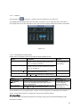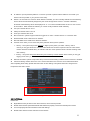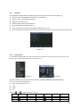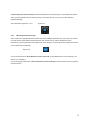
1
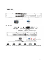
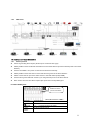
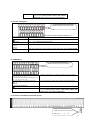
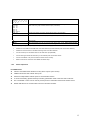
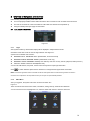
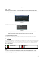
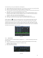
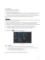
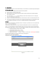
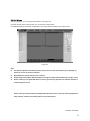
QUICK STARTUP GUIDE VR Series Embedded DVR Systems VR LT VR EM VR PRO Table of Contents 1 Hardware Installation and Connection .......................................................................... 5 1.1 Unpacked and Check the DVR ........................................................................... 5 1.2 About Front Panel and Real Panel .................................................................... 5 1.3 Cables and Settings ............................................................................................. 5 1.4 HDD Installation .................................................................................................... 5 1.4.1 1.4.2 2 or 4 HDD Series ...................................................................................... 5 2 HDD Series .............................................................................................. 6 1.5 Rack Installation .................................................................................................... 6 1.6 Front Panel............................................................................................................. 6 1.7 Rear Panel ............................................................................................................. 8 1.7.1 1.8 DVR Rear Panel......................................................................................... 8 Connection Sample: ........................................................................................... 10 Refer to the following figure for sample connection................................................. 10 1.8.1 LT Series ................................................................................................... 10 1.8.2 EM Series .................................................................................................. 10 1.8.3 PRO Series ............................................................................................... 11 1.9 Alarm Input and Output Connections .............................................................. 11 1.9.1 1.9.2 2 Alarm Input Port ....................................................................................... 11 Alarm Output Port .................................................................................... 13 Overview of Navigation and Controls.......................................................................... 14 2.1 Login, Logout & Main Menu .............................................................................. 14 2.1.1 2.1.2 2.1.3 2.1.4 Login .......................................................................................................... 14 Main Menu ................................................................................................ 14 Logout ........................................................................................................ 15 Auto Resume after Power Failure ......................................................... 15 2.2 Live Viewing ......................................................................................................... 15 2.3 Schedule............................................................................................................... 15 2 2.3.1 2.3.2 2.3.3 2.3.4 2.3.5 2.3.6 2.3.7 2.4 Network Setup ..................................................................................................... 22 2.5 Pan/Tilt/Zoom ...................................................................................................... 23 2.5.1 2.5.2 2.5.3 3 Manual Record ......................................................................................... 16 Encode....................................................................................................... 17 Snapshot ................................................................................................... 17 Image FTP ................................................................................................ 19 Snapshot Disk (For selected series only) ............................................ 19 Search and Playback .............................................................................. 20 Basic Operation ........................................................................................ 21 PTZ Setup ................................................................................................. 24 PTZ Operation .......................................................................................... 24 3D Intelligent Positioning Key ................................................................ 25 Web Operation................................................................................................................ 26 3.1 Network Connection ........................................................................................... 26 3.2 Login ..................................................................................................................... 26 3.3 Main Window ....................................................................................................... 27 Check your Documentation and Application Disc that came in with your CCTV equipment for other manuals, software and training video for your DVR system. Contact your original DVR dealer, seller or installer if you have any questions for software updates or technical support issues. 3 Welcome!!! Thank you for purchasing Optiview VR Embedded DVR Series. This quick startup guide will help you become familiar with DVR basic functionalities. Some of the topic includes hard drive installation, cable connection and general operations such as system setup, record, search, backup, alarm setup, PTZ operation, and remote access through the network. Please note that your DVR already have a hard drive pre-installed. You are advised to read carefully the following safeguard and warning information! Important Safeguard and Warning 1.Electrical safety All installation and cabling should conform to your local electrical safety codes. We assume no liability or responsibility for all the fires or electrical shock caused by improper handling and/or installation. 2.Transportation and Storage Security There must be no excessive stress, severe vibration, high humidity or moisture during transportation, storage and installation of this product. 3.Installation Keep it installed in an upward position on top of a sturdy desktop or shelves. Handle with care. Do not apply power to the DVR until all the wiring and cable installation is done. Do not place objects on top of the DVR to avoid damage. Warranty is voided if damaged on the DVR is caused by improper storage. 4.Qualified engineers needed All the troubleshooting and repair work should be done by the qualified service engineers only. We are not liable for any problems caused by unauthorized modifications or repair of the DVR. Contact only the original seller of your DVR system for technical support. 5.Environment The DVR should be installed in a cool and dry place away from direct sunlight, high humidity or moisture, flammable and explosive substances or any other unnecessary items that could possibly cause damage to your DVR system. 6. Accessories Be sure to use all the accessories recommended by manufacturer. Please open the package and check all the components before installation. Contact your local seller/installer ASAP if something is missing in your package. 7. Lithium battery Improper battery use may result in fire, explosion, or personal injury! When replacing the battery, please make sure you are using the same model and specifications to avoid damage to your DVR system. 4 1 Hardware Installation and Connection Note: All the installation and operations should conform to your local electric safety rules. 1.1 Unpacked and Check the DVR When you receive the DVR from the forwarding agent, please check whether there is any visible damage. The protective materials used for the package of the DVR can protect most accidental clashes during transportation. Then you can open the box to check the accessories. Please check the items in accordance with the list on the warranty card (Remote control is optional). Finally you can remove the protective film of the DVR. Note Remote control is not a standard accessory and it is not included in the accessory bag. 1.2 About Front Panel and Real Panel For detail information of the function keys at the front and rear panels, please refer to the User’s Manual included in the resource CD. 1.3 Cables and Settings Your DVR system was already pre-inspected at the Optiview OEM facilities where all the settings and cables were already checked and verified by a service technician. 1.4 HDD Installation Hard drive is already pre-installed on your DVR system. This section is only a reference in case you are adding more hard drive. 1.4.1 2 or 4 HDD Series There are three model series for the VR Embedded DVR systems. Please refer to you DVR specification sheet at the DVR User’s Manual for the total physical hard drive capacity on your system. Use HDD with 7200rpm or higher. It has no requirement for HDD capacity. You can refer to the user’s manual for recommended HDD brand. VRLT – 1 hard drive, max. 2TB VREM – 1 hard drive or 2 hard drives if there is no DVD drive installed, max. 2TB/HDD VRPRO – 6 hard drive or 8 hard drives if there is no DVD drive installed, max. 2TB/HDD Please follow the instructions below to install hard disk. 1. Loosen the screws of the 2. Line up the HDD to the four upper cover. holes of the HDD bracket. 3. Use four screws to fix HDD. 5 4. Unfasten the HDD power 5. Use the special data cable to 6. Insert the HDD power cable. Close the cable. connect the HDD and the SATA port chassis and fix the screws to secure firmly. After completing HDD installation, please check connection of data ribbon and power cord. 1.4.2 2 HDD Series This series DVR supports 2 HDDs. Please use HDD of 7200rpm or higher. It has no requirement for HDD capacity. You can refer to the appendix for recommended HDD brand. Please follow the above steps (chapter 1.4.1) to install the HDD. Note If your HDD is less than (or equal to) 4 HDD, you do not need to remove the HDD bracket, you can install HDD in the bracket directly. When you secure the HDD, please make sure the HDD installation direction in the up/down bracket are the same. 1.5 Rack Installation Use proper rack screws to fix the unit Please make sure the indoor temperature is below 35℃ (95°f). Please make sure there is 15cm (6 inches) space around the device to guarantee sound and air ventilation. Please install from the bottom to the top. If there are other servers connected in the server rack, please take precautionary measures to make sure server rack power is not overloaded. After completing HDD installation, please check connection of data ribbon and power cord. 1.6 Front Panel VR Embedded DVR LT series front panel: VR Embedded DVR EM series front panel: VR Embedded DVR PRO series front panel: Figure 1-1 6 Please refer to the following sheet for front panel button information. Name Icon Function Power button, press this button for three seconds to boot up or shut down DVR. Power button To connect USB storage device, USB mouse. USB port Activate current control, modify setup, and then move up and down. Up/ Down Increase/decrease numeral. 、 Assistant function such as PTZ menu. Input number 1/4. Shift current activated control, and then move left and right. Left/ Right When playback, click these buttons to control playback bar. Input number 2/3. Confirm current operation Enter ENTER Go to default button Go to menu Reverse/Pause In normal playback or pause mode, click this button to reverse Playback Input number 5. Play/Pause In normal playback click this button to pause playback In pause mode, click this button to resume playback. Input number 6. Multiple slow play speeds or normal playback. Input number 8. Slow play Fast play Various fast speeds and normal playback. Input number 7. Play previous I In playback mode, playback the previous video. Input number 9. Play Next I In playback mode, playback the next video Input number 0. ESC ESC Go to previous menu, or cancel current operation. When playback, click it to restore real-time monitor mode. One-window monitor mode, click this button to display assistant function: PTZ control and image color. Assistant Shift Fn Backspace function: in numeral control or text control, press it for 1.5 seconds to delete the previous character before the cursor. In motion detection setup, working with Fn and direction keys to realize setup. In text mode, click it to switch between numeral, English character(small/capitalized) and etc. In HDD management interface, you can click it to switch HDD record information and other information (Menu prompt) Realize other special functions. In textbox, click this button to switch between numeral, English(Small/Capitalized),donation and etc. 7 Record REC Manually stop/start recording, working with direction keys Or numeral keys to select the recording channel. Remote control indication light ACT Remote control indication light Status indication light Status If there is Fn indication light, current status indication light is null. Power indication light Power Power indication light Record light 1-16 System is recording or not. It becomes on when system is recording. IR Receiver IR It is to receive the signal from the remote control. CD-ROM button Pop-up or insert the CD. 1.7 Rear Panel 1.7.1 DVR Rear Panel 4/8CH LT series rear panel 1 2 3 4 5 6 7 8 9 10 4-8CH VR LT Series Video input Audio input Video CVBS output Audio output Network port USB port Video VGA output Power input port Alarm input/alarm output/RS485 port Power button 16CH LT series rear panel 1 2 3 4 5 6 7 8 9 10 11 12 VR16LT Rear Panel Video input Audio input Video CVBS output Audio output Network port USB port HDMI port RS232 port Video VGA output Alarm input/alarm output/RS485 port Power input port Power button 8 EM series DVR rear panel is shown as below. See Figure 1-4. Figure 1-4 1 2 3 4 5 6 7 8 9 10 11 12 VR EM Series Rear Panel Video input Audio input Audio output Video CVBS output USB port Network port HDMI port RS232 port Video VGA output Alarm input/alarm output/RS485 port Power button Power socket PRO Series DVR rear panel is shown as below. See Figure 1-5 1 2 3 4 5 6 7 8 9 10 11 12 VRPRO Series Rear Panel Power button Power input port Fan Loop video output 1st to 4th-channel audio input Video input DB25 port (5th to 16th-channel audio input port) Audio output Bidirectional talk input port Bidirectional talk output port Network port eSATA port 13 RS232 port 14 15 USB port HDMI port 16 Video VGA output 17 Alarm input/alarm output/RS485 port 18 Video CVBS output 19 Video matrix output 9 1.8 Connection Sample: Refer to the following figure for sample connection 1.8.1 LT Series 1.8.2 EM Series 10 1.8.3 PRO Series 1.9 Alarm Input and Output Connections 1.9.1 Alarm Input Port 4/8/16-ch grounding alarm inputs. (Normal open or Normal close type) Please parallel connect COM end and GND end of the alarm detector (Provide external power to the alarm detector). Use the controllable +12V power to reset the smoke sensor remotely. Please parallel connect the Ground of the DVR and the ground of the alarm detector. Please connect the NC port of the alarm sensor to the DVR alarm input(ALARM) Use the same ground with that of DVR if you using external power to the alarm device. Note: VR4LT does not have Alarm Input/output ports and no PTZ (RS485) port. For VR8LT DVR System RS485 Connection port for PTZ camera (Alarm) Rear Panel for VR8LT Parameter Grounding Alarm Ground line Alarm Input 1, 2, …, 8. It becomes valid in low voltage. 1-NO C, 2-NO C, 3-NO C Three NO activation outputs. 11 485 A/B 485 communication port. They are used to control devices such as PTZ. Please parallel connect 120Ω between RS485 A/B cables if there are too many PTZ decoders. For VR16LT DVR System RS485 Connection port for PTZ camera (Alarm) Rear Panel for VR16LT DVR System Parameter Grounding Alarm Ground line Alarm Input 1, 2, …, 16.. It becomes valid in low voltage. 1-NO C, 2-NO C, 3-NO C 485 A/B Three NO activation outputs. 485 communication port. They are used to control devices such as PTZ. Please parallel connect 120Ω between RS485 A/B cables if there are too many PTZ decoders. For VREM Series RS485 Connection port for PTZ camera In the second line, from the left to the right,: 1, 2,3,4,5,6,7,8, In the first line, from the left to the right: 9,10, 11,12,13,14,15,16 In the second line, from the left to the right: NO1 C1, NO2 C2, In the first line, the NO3 C3 ALARM 1 to ALARM 16. The alarm becomes active in low voltage. The three groups of normal open activation outputs(on/off button) Ground cable. RS485 A/B RS485 communication port. They are used to control devices such as PTZ. Please parallel connect 120Ω between RS485 A/B cables if there are too many PTZ decoders. For VR16PRO and VR32PRO Embedded DVR Systems RS485 Connection port for PTZ camera Data polarity: + =A -- = B 12 In the first line, from the left to the right,: 1,2,3,4,5,6, 7,8,9,10,11,12,13, 14,15,16 In the second line, from the left to the right: NO1 C1, NO2 C2, NO3 C3, NO4 C4, NO5 C5 NC5 CTRL 12V +12V ALARM 1 to ALARM 16. The alarm becomes active in low voltage. The first four are four groups of normal open activation output (on/off button) NO5 C5 NC5 is a group of NO/NC activation output (on/off button) Control power output. You need to close the device power to cancel the alarm. It is external power input. Need the peripheral equipment to provide +12V power (below 1A). Ground cable. 485 communication port. They are used to control devices such as PTZ. Please parallel connect 120Ω between RS485 A/B cables if there are too many PTZ decoders. 485 A/B • 16-port grounding alarm inputs. (Normal open or Normal close type) • Parallel connect COM end and GND end of the alarm detector (Provide external power to the alarm detector). • Parallel connect the Ground of the DVR and the ground of the alarm detector. • Connect the NC port of the alarm sensor to the DVR alarm input(ALARM) • Use the same ground with that of DVR if you use external power to the alarm device. • Use the controllable +12V power to reset the smoke sensor remotely. • Refer to DVR User’s manual for other details with Alarm setup. 1.9.2 Alarm Output Port For VREM series: VR16LT and VREM series DVR has 3 relay alarm outputs. (NO contact). VRPRO series DVR has 6 Alarm OUT ports Provide an independent external power to external alarm device. To avoid overloading, please carefully read relay parameters sheet in the DVR User’s Manual. The controllable +12Vdc can be used to provide power to small alarm devices like smoke sensor. RS485 A/B cable is for the A/B cable of the PTZ decoder/controller. 13 2 Overview of Navigation and Controls Before starting the DVR system, please make sure: You have properly installed camera cables and all the other connections such as alarm and PTZ camera. The DVR is connected to a clean and stable AC wall outlet and cameras are all powered up. Using UPS battery backup is highly recommended. 2.1 Login, Logout & Main Menu Figure 2-1 2.1.1 Login After system booted up, default video display will be displayed in multiple-window mode. Click Enter or left click mouse to view the login interface. See Figure 2-1. System has four default user accounts: Username: admin. Password: admin. (administrator, local and network) Username: 888888. Password: 888888. (administrator, local only) Username: 666666. Passwords: 666666(Lower authority user who can only monitor, playback, backup and etc.) Username: default. Password: default(hidden user) You can use USB mouse, front panel, remote control or keyboard to input login information. Click to switch between alpha-numeric characters or change between upper/lower case letters. Note: Three times login failure within 30 minutes will result in DVR system alarm and five times login failure will result in account lock out. Optiview is not responsible in case you lose your own personalized password. 2.1.2 Main Menu After you logged in, the system main menu is shown as below. See Figure 2-2. There are total six sub-menu items: search, information, setting, backup, advanced and shutdown. You can move the cursor to highlight the icon, and then double click mouse to enter the sub-menu. 14 Figure 2-2 2.1.3 Logout There are two ways for you to log out. You can use the OSD menu or the power button of the DVR system. a. Logout Option 1: from the main menu, click shutdown button, select “logout….” from the drop-down box then click OK. See Figure 2-3. Figure 2-3 Other options at the “shutdown” menu . See Figure 2-4. Figure 2-4 b. Logout Option 2: press power button at the front panel for at least 3 seconds to stop all system operations, then you can press the power button at the front panel to turn off the DVR. 2.1.4 Auto Resume after Power Failure The DVR system will automatically record video and resume previous working status after power failure. 2.2 Live Viewing After you logged in, by default, the system will be in live viewing mode. The system date, time and channel name will be displayed on the screen. If you want to change the system date and time, refer to general settings (Main Menu->Setting->General). If you need to modify the channel name, please refer to the display settings (Main Menu->Setting->Display) 1 Recording status 3 Video loss 2 Motion detection 4 Camera lock 2.3 Schedule Note: You need to have proper rights to implement the Schedule. Make sure the HDDs have been properly installed. After the system boot up, it is in default 24-hour regular mode. You can set record type and time schedule at the schedule menu interface. 15 In the main menu, you can go to schedule menu. See Figure 2-5. Channel: Please select the channel number first. You can select “all” if you want to set for all the channels. Week day: There are eight options: ranging from Saturday to Sunday and “All”. Pre-record: System can pre-record the video before the event is written into the hard drive as video file. The value ranges from 1 up to 30 seconds depending on the bit stream. Redundancy: System supports redundancy backup function. You can highlight Redundancy button to activate this function. Please note, before enabling this function, you need to set at least one HDD as “redundant”. (Main menu->Advanced->HDD Management). Snapshot: You can enable this function to take snapshot image when alarm occurs. Record types: There are four record types: regular, motion detection (MD), Alarm, MD & alarm. Please highlight icon to select the corresponding function. After completing all the settings, click save button and the current menu goes back to the previous menu. At the bottom of the menu are color bars indicating the type of record mode. As a reference, green color stands for regular recording, yellow color stands for motion detection and red color stands for alarm recording. Note: when “MD & Alarm” is enabled, DVR system will not record neither on motion detect (MD) only nor does the “alarm” only. Do not select MD and Alarm if the “MD & Alarm” is already selected. Figure 2-5 2.3.1 Manual Record There are three options: schedule/manual/stop. Highlight icon“○” to select corresponding channel. See Figure 2-6 below. Manual: The highest priority. After manual setup, all selected channels will begin manual recording. Schedule: Channel records as you have set in “Schedule” setup (Main Menu->Setting->Schedule) Stop: All channels stop recording. Figure 2-6 16 2.3.2 Encode Encode interface is shown as in Figure 2-7. Channel: Select the channel you want. Compression: System supports H.264. Resolution: System supports various resolutions, you can select from the dropdown list. For this model, main stream supports D1/HD1/BCIF/CIF/QCIF. Please note the extra stream resolution may vary depending on series model. Refer to DVR model’s specification sheet or DVR user manual for details. Frame rate: ranges from 1f/s to 25f/s in NTSC mode and 1f/s to 30f/s in PAL mode. Note: 2 HDD Series If the 1-channel resolution is D1 and the frame rate is more than 6f/s (or 7f/s in NTSC), the extra stream frame rate shall be below 6f/s (or below 7f/s NTSC). Bit rate type: system supports two types: CBR and VBR. In VBR mode, you can set video quality. Quality: There are six levels ranging from 1 to 6. The sixth level has the highest image quality. Audio/Video: you can enable or disable the video/audio. Please note the video is enabled for main stream by default. For extra stream, please enable video first and followed by audio if needed. Snapshot: Click snapshot button, this menu includes the four items: mode/image size/image quality/snapshot frequency. Please refer to chapter 2.3.3 for detailed information. Please highlight icon to select the corresponding function. Figure 2-7 2.3.3 Snapshot 2.3.3.1 Schedule Snapshot – three menu interfaces should be setup to enable this feature: a. In Encode interface, click snapshot button to input snapshot mode, size, quality and frequency. b. In General interface please input upload interval. c. In Schedule interface, please enable snapshot function. Please refer to the following figure for detail information. See Figure 2-8. 17 Figure 2-8 2.3.3.2 Activation Snapshot Please follow the steps listed below to enable the activation snapshot function. After you enabled this function, DVR system can take snapshot when a corresponding alarm occurred. In Encode interface, click snapshot button to input snapshot mode, size, quality and frequency. In General interface, please input upload interval. In Detect interface, please enable snapshot function for specified channels. In Alarm interface, please enable snapshot function for specified channels. Please refer to the following figure for detail information. See Figure 2-9. Figure 2-9 18 2.3.3.3 Priority The “Activation snapshot” has a higher priority than a “Scheduled Snapshot”. When both snapshot options are enabled and an alarm occurs, the Activation snapshot will supersede the Scheduled Snapshot. 2.3.4 Image FTP In Network interface, you can set FTP server information. Please enable FTP function and then click save button. You need to have your private FTP server on your network to have this option to work. Make sure FTP server user account, permissions and login information was already setup at your FTP server. See Figure 2-10.Please refer to the User’s Manual included in the resource CD for detailed information. Enable schedule snapshot or activation snapshot (Chapter 2.3.3) and then system can upload the image file to the FTP server. Please input the corresponding private FTP information here if you need to upload image via FTP. Figure 2-10 2.3.5 Snapshot Disk (For selected series only) Set one disk as snapshot (Main menu->Advanced->HDD management) and then click execute button. See Figure 2-11. System needs to reboot to get current setup activated. Figure 2-11 All scheduled snapshot files or activated snapshot files will be saved in the snapshot disk. You can search the corresponding images via Web interface only. See Figure 2-12. 19 Select a file and then click here to view Select search image content. engine here There are max 100 files in one page. Click here to view more. You can see result here. Double click file name, you can view the image content Figure 2-12 2.3.6 Search and Playback Click search button in the main menu, search interface is shown as below. See Figure 2-13. Usually there are three file types: R: Regular recording file.- A: External alarm recording file. M: Motion detection recording file Playback control bar Select playback mode here: 4-ch or All-channel Set search Figure setup 2-13 here :( Time/Channel/Type) 20 Please refer to the following sheet for more information. 2.3.7 Serial Number 1 2 3 4 5 6 7 8 9 10 11 12 13 14 Function Play Backward Stop Slow play Fast play Previous frame Next frame Volume Previous file Next channel Next file Previous channel Search Backup 15 Clip Basic Operation 2.3.7.1 Playback Operation There are various search modes: video type, channel number or time. The system can max display 128 files in one screen. You can use page up/down button to view if there are more than one page. Select the file name and double click mouse (or click enter button) to view file content. 2.3.7.2 Playback Mode There are two playback modes: 4-ch and all-channel. In 4-ch playback mode, you can select the 1/2/3/4-ch playback depending on your requirement. In “all-channel” mode, system can playback in full channels. Please note the 4-ch has no all-channel playback mode. 2.3.7.3 Accurate playback Input specific time (h/m/s) in the time column and then click playback button, the system will playback specific date and time based on your input information. 2.3.7.4 Synchronized playback function when playback During playback process, click numeral key, system can switch to the corresponding channel video of the same time. 2.3.7.5 Digital zoom When the system is in full-screen playback mode, press left button of your mouse, hold it and drag your mouse in the screen to select a section and then left click mouse to activate digital zoom. To exit digital zoom, right click mouse to exit. 2.3.7.6 File backup System supports backup operation during search. You can draw a √ before file names (multiple choices). Then click backup button (Button 14 in Figure 2-13) Fn in one channel, system max displays 32 files. If you want to clip a period of file, please playback the original file first. Click the (Button 15 in Figure 2-13) at the start point (that is your new file beginning point). Drag the file to the end point (that is your new file end point) and then click the again. Click the backup button (Button 14 in Figure 2-13) to save your current new file. 21 2.3.7.7 Calendar Click calendar icon in Figure 2-13, system pops up a calendar for your reference. The highlighted date indicates there are record files on that day. You can click blue date to view file list. In the figure below, there are video files on June 13th and 14th. Simply double click the date to view file list. Figure 2-14 2.3.7.8 Slow playback and fast playback Please refer to the following sheet for slow play and fast playback function. Button Illustration Remarks Fast play button In playback mode, click this button to switch between various fast play modes such as fast play 1, fast play 2 and more. In playback mode, click this button to switch between various slow play modes such as slow play 1 or slow play 2. Frame rate may vary due to depending of DVR settings. Slow play button ► Play/Pause► Previous/next In slow playback mode, click this button to switch between play/pause modes. In playback mode, you can click │ and to view previous or next video in current channel. 2.3.7.9 Backward playback and frame by frame playback Button Illustration Remarks Backward play: in playback interface. In normal playback mode, left click backward play button, system begins backward playback. Double click backward play button again, system goes to pause mode. Click pause button in normal playback mode, you can use │ and │ to view frame by frame. When system is in backward play or frame by frame playback mode, you can click play button►/ to go to normal playback. Manual playback frame by frame. Note: All the operations such as playback speed, channel, time and progress have relationship with hardware version. Some series DVRs do not support some functions or playback speeds. 2.4 Network Setup On this menu screen, the network information can be setup to suite your private network addressing range. See Figure 2-15 below. 22 IP address: input IP(network) address. It could be a private or public network address. Check with your Internet service provider or your private router setup. DHCP: It is auto search IP function. When DHCP is enabled, you cannot modify IP/Subnet mask /Gateway. These values are automatically assigned by the router through DHCP function. If DHCP is disabled, IP/Subnet mask/Gateway values are displayed as “0”. You need to disable DHCP function to view current IP information. When PPPoE is enabled, you cannot modify IP/Subnet mask /Gateway. TCP port: Default value is 37777. UDP port: Default value is 37778. HTTP port: Default value is 80. Max connection: system support maximum logged in 10 users. 0 means there is no connection limit. Preferred DNS server: DNS server IP address. Alternate DNS server: DNS server alternate address. Transfer mode: Here you can select the priority between fluency/video qualities. Latency - The system will put the real-time in higher priority when you select "Latency" which means you may get frame loss when the network/Internet connection speed is slow for video stream transfer because the DVR will try to maintain “real time” video speed at client end while sending video files remotely. Fluency - the system will protect the fluency and continuity of video stream which means you may get lagging issue when you have a slow network or Internet connection. Network download: System will prioritize the process the downloading of data first if this function is enabled. Advanced setting: Please refer to the user’s manual included in the resource CD for detail information. After completing all the setup, please click save button to save settings. The system OSD menu will go back to the previous OSD menu screen. Figure 2-15 2.5 Pan/Tilt/Zoom Please note: Slight difference may be found in the user’s interface, due to various protocols. Please make sure the speed dome RS485 data cables are properly connected to the A/B ports of DVR. You have properly set PTZ information at the DVR settings. Please switch camera monitor channel to current window. 23 2.5.1 PTZ Setup The pan/tilt/zoom setup includes the following steps. First, select camera channel. See Figure 2-16. Protocol: Select corresponding PTZ protocol such as PELCOD. Address: Input corresponding PTZ address. Baud rate: Select baud rate. Data bit: Select data bit. Default value is 8. Stop bit: Select stop bit. Default value is 1. Parity: There are three choices: none/odd/even. Default value is none. After completing all the setup, please click save button, the system will go back to the previous OSD menu. Figure 2-16 2.5.2 PTZ Operation In one window display mode, right click mouse (click “Fn” Button in the front panel or click “Fn” key in the remote control). The interface is shown as in Figure 2-17. Figure 2-17 Figure 2-18 Click Pan/Tilt/Zoom, the interface is shown as below. See Error! Reference source not found.. Here you can set the following items: Step: value ranges from 1 to 8. Zoom Focus Iris Click icon Name Zoom Focus Iris and to adjust zoom, focus and iris. Function Function Shortcut key key Near ► Near close Function key function Far Far Open Shortcut Key ► 24 In Error! Reference source not found., please click direction arrows (See Figure 2-19) to adjust PTZ position. There are total 8 direction arrows. Please note if you use remote control, you can use just four directions (Up/down/left/right). The speed value ranges from 1 to 8. 2.5.3 Figure 2-19 3D Intelligent Positioning Key At the center of the eight directional arrow buttons is the 3D intelligent positioning key. See Figure 2-20. Please note, this function needs protocol supported by the PTZ camera and can only be operated by mouse. Click this key, system goes back to the single screen mode. Drag the mouse in the screen to adjust section size. It can activate PTZ automatically. Figure 2-20 You can click set button in Error! Reference source not found. (or click REC button in the front panel) to set preset, tour, and pattern. You can click page switch button in Error! Reference source not found.(or click Fn button in the front panel) to call main function. 25 3 Web Operation VR Embedded DVR systems can be accessed remotely on a local network or via Internet using Internet Explorer. 3.1 Network Connection Check the following before making a remote web client access operation: Physical network connection has been setup. DVR and Client PC can communicate with each other via network. Please refer to network setup(main menu->setting->network) Use command ping ***.***.***.***(* DVR IP address) to check if the connection is OK or not. Usually the return TTL value should be less than 255. System can automatically download latest web control and the new version can overwrite the previous one. If you need to un-install the web controls due to corrupted ActiveX files, please run uninstall webrec2.0.bat to auto delete the control files or you can go to C:\Program Files\webrec to delete Single folder. 3.2 Login Open IE and input DVR address in the address column. For example, if your DVR IP is 10.10.3.16, please enter http:// 10.10.3.16 in IE address box. System pops up warning information to ask you whether to install webrec.cab control or not. Please click yes button. If you can’t download the ActiveX file, please modify your IE security setup. Here’s the ActiveX settings that need to be modify: Open IE >>Tools>> go to Internet Options>>Security>>click “Internet>>Custom Level>>> a. Automatic prompting for ActiveX controls – Enable b. Download signed ActiveX controls – prompt c. Download unsigned ActiveX controls – prompt d. Initialize ActiveX controls …. – prompt >>> Click OK >> YES>> OK>>> Close all open IE windows After the ActiveX installation, the interface is shown as below. See Figure 3-1. Please input your user name and password. Default factory name is admin and password is admin. Figure 3-1 26 3.3 Main Window After you logged in, you can see the main window. See Figure 3-2. Click the channel name on the left side; you can view the real-time video. For detailed operation information, please refer to the User’s Manual included in the resources CD. Figure 3-2 Note For detailed operation introduction, please refer to our resource CD included in your package for electronic version of the User’s Manual. Slight difference may be found in user interface. All the design and software GUI are subject to change for improvement without prior written notice. Please contact your original DVR dealer or seller if you have any questions for software updates or technical support issues. Please check your Documentation and Application Disc that came in with your CCTV equipment for other manuals, software and training video for your DVR system. Released JB.3182011 27