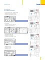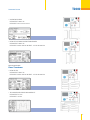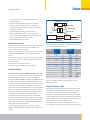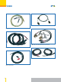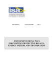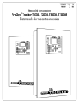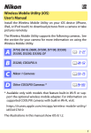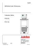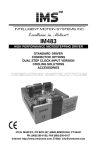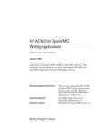
1
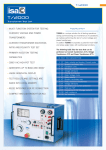
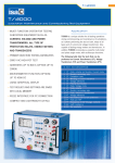
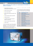
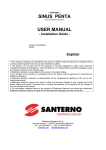
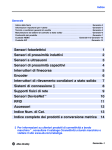
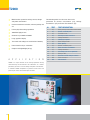
T2000
•
Multi function system for testing: current, voltage
and power transformers
•
Current transformer excitation, ratio and polarity test
set
•
•
•
•
•
•
•
Primary injection testing capabilities
A
P
3000 V AC high-pot test
Generates up to 800A and 3000V
Large graphical display
Test results and settings are saved into local memory
RS232 interface for pc connection
Compact and lightweight (26 kg)
P
L
I
C
A T
I
O
N
T2000 is a unique solution for all testing operations during
commissioning and maintenance of substations, as it allows
performing the test of current voltage and power transformers.
In addition T2000 incorporates a powerful multi-meter and
phase angle meter, with oscilloscope functions.
68
The following table lists the tests that can be
performed on Current transformers (CT), Voltage
Transformers (VT) and Power Transformers (PT).
N.
TEST
1
2
3
4
5
6
7
8
9
10
11
12
13
14
15
16
CT
CT
CT
CT
CT
CT
CT
VT
VT
VT
VT
VT
PT
PT
GR
GR
TEST DESCRIPTION
Ratio, polarity and burden, Current mode
Burden; secondary side
Excitation curve
Winding or burden resistance
Voltage withstand
Polarity by impulses
Ratio, Voltage mode
Ratio; polarity
Burden, secondary side
Ratio, electronic transformers
Voltage withstand
Secondary over-current protection
Ratio per TAP
Resistance of TAP Changer contacts
Earth resistance
Soil resistività
Transformer Test Set
T2000
Typical application
Test of Current Transformer
• CT RATIO V AND POLARITY - VOLTAGE METHOD
USED OUTPUT: 90 V, 250 V or 3000 V AC.
USED INPUT: LOW AC VOLTAGE - 10 V AC.
• CT EXCITATION
USED OUTPUT: 90 V, 250 V or 3000 V AC.
USED INPUT: Internal measurement.
• CT BURDEN SECONDARY SIDE:
USED OUTPUT: 10 A or 40 A AC.
USED INPUT: LOW AC VOLTAGE - 10 V AC.
• WINDING RESISTANCE:
USED OUTPUT: 6 A DC.
USED INPUT: 10 V DC.
69
T2000
• VOLTAGE WITHSTAND:
USED OUTPUT: 3000 V AC.
USED INPUT: Internal measurement.
• CT RATIO AND POLARITY - CURRENT METHOD
USED OUTPUT: 800 A AC.
USED INPUT: LOW AC CURRENT - 10 A AC.
Typical application
Test of Voltage Transformer
• VT RATIO AND POLARITY
USED OUTPUT: 3000 V AC.
USED INPUT: LOW or HIGH AC VOLTAGE - 10 V AC OR 600 V AC.
• VT BURDEN
USED OUTPUT: 10 A AC.
USED INPUT: LOW or HIGH AC VOLTAGE - 10 V AC OR 600 V AC.
70
Transformer Test Set
T2000
• VOLTAGE WITHSTAND
USED OUTPUT: 3000 V AC.
USED INPUT: Internal measurement.
• RATIO OF ELECTRONIC VOLTAGE TRANSFORMER
USED OUTPUT: 3000 V AC.
USED INPUT: LOW or HIGH AC VOLTAGE - 10 V AC OR 600 V AC.
Typical application
Power Transformer
• RATIO PER TAP
USED OUTPUT: 3000 V AC.
USED INPUT: LOW or HIGH AC VOLTAGE - 10 V AC OR 600 V AC.
• TAP CHANGER RESISTANCE AND CONTINUITY
USED OUTPUT: 6 A DC.
USED INPUT: 10 V DC.
71
T2000
SYSTEM DESCRIPTION
T2000 contains one generator:
• Main generator. It has six outputs: High AC current; Low AC
current; Low DC current; Current impulses; High AC voltage;
Low AC voltage 1.
All outputs are adjustable and metered on the large, graphic
LCD display. With the multi-purpose control knob and the
graphic LCD display it is possible to enter the MENU mode,
that allows to control all functions, and makes T2000 the
most powerful testing device, with manual and automatic
testing capabilities, and with the possibility to transfer test
results to a PC via the RS232 interface. These results can be
recorded, displayed and analysed by the powerful TDMS
software, which operates with all WINDOWS versions, starting
from WINDOWS 98 included.
Additional features are:
. Oscilloscope function: it is possible to display the current
and voltage waveform measured;
. Two independent measurement inputs, for current and
voltage, and with High and Low inputs each, allow
measuring CT or VT outputs or any other source;
. The optional thermal printer gives the immediate printout of
the CT saturation curve and other test results;
The instrument is housed in a transportable aluminium box,
which is provided with removable cover and handles for ease
of transportation.
Note: WINDOWS is a trademark of MICROSOFT inc.
HIGH POWER RANGE
CURRENT
OUTPUT
A
100
150
200
400
600
800
High AC current output
APPLICATION:
. CT TESTING: RATIO, POLARITY, BURDEN
. RELAY TESTING,
. PRIMARY INJECTION
72
LOAD
TIME
s
600
800
1000
1600
2000
2000
RECOVERY
TIME
min
steady
15 min
4 min
15
5
1
30
15
5
3
2
LOW POWER RANGE
CURRENT
OUTPUT
A
OUTPUT
POWER
VA
30
50
LOAD
TIME
s
60
60
RECOVERY
TIME
min
steady
10 min
10
Low AC current output
APPLICATION:
. CT TESTING: BURDEN, SECONDARY SIDE
. VT TESTING: OVERCURRENT PROTECTION
HIGH POWER RANGE
RANGE CURRENT
A
OUTPUT
AC
A
40
T2000 Specification
Main Generator
The main generator has six outputs: High AC current; Low AC
current; Low DC current; Current impulses; High AC voltage;
Low AC voltage. Output adjustment is performed via a knob.
The following specification applies to the separate usage of
these outputs.
OUTPUT
POWER
VA
10
12
18
24
36
48
60
5
7.5
10
15
20
output
POWER
VA
300
800
1000
400
800
1000
LOAD
TIME
s
ReCOVERY
TIME
min
steady
15 min
4 min
15
5
1
steady
15 min
60
30
15
30
15
5
3
2
30
15
10
5
T2000
Transformer Test Set
LOW POWER RANGE
RANGE CURRENT
A
OUTPUT
AC
A
40
10
12
18
24
36
5
6
7
10
output
POWER
VA
60
60
LOAD
TIME
s
ReCOVERY
TIME
min
steady
10 min
60
1
steady
10 min
60
1
30
10
2
45
2
2
1200
1200
6
3
1
0
2
8
0
18
8
LOAD
TIME
min
steady
steady
steady
VOLTAGE CURRENT
OUTPUT OUTPUT
V
A
600
500
RECOVERY
TIME
min
-
3000
0.2
0.6
600
1800
STEADY
1
STEADY
1
8
0.1
0.2
OUTPUT
POWER
VA
60
120
LOAD
TIME
min
RECOVERY
TIME
min
STEADY
1
8
VOLTAGE VOLTAGE
V
OUTPUT
AC
A
250
200
OUTPUT
POWER
VA
125
200
LOAD
TIME
min
STEADY
3
RECOVERY
TIME
min
9
Output measurements
Current and voltage AC and DC outputs measurement
accuracy: ± 0.5%.
Phase angle measurement accuracy: 1°.
Frequency accuracy: 1 mHz.
Other measurements available on T2000:
The following measurement are calculated from the T2000
generated outputs:
External Inputs Measurement
Current measurements
. Two inputs: 20 mA AC or DC or 10 A AC.
. Accuracy: 0.5%
Possibility to display the current waveform.
HIGH POWER RANGE
3000 V version
LOAD
TIME
min
RECOVERY
TIME
min
Measuring Section
High AC voltage output
Two version are available: 3000V or 1200V output
APPLICATION:
. CT TESTING: EXCITATION CURVE, VOLTAGE WITHSTAND
. VT TESTING: RATIO, POLARITY, ELECTRONIC VOLTAGE
TRANSFORMER
. PT TESTING: RATIO PER TAP
OUTPUT
POWER
VA
600
1800
LOAD
TIME
min
Low AC voltage output
APPLICATION:
. CT TESTING: RATIO WITH VOLTAGE METHOD
. VT TESTING: BURDEN SECONDARY SIDE
250
Current impulses output
APPLICATION:
. CT TESTING: POLARITY TEST WITH IMPULSE METHOD
. Current range: from 0 to 10 A peak.
VOLTAGE CURRENT
OUTPUT OUTPUT
V
A
0.5
1.5
OUTPUT
POWER
VA
LOW POWER RANGE
Low DC current output
APPLICATION:
. CT TESTING: WINDING RESISTANCE, BURDEN RESISTANCE
. PT TESTING: TAP-CHANGER CONTACT RESISTANCE
CURRENT LOAD
OUTPUT
OUTPUT RESISTANCE POWER
A
Ohm
W
In alternative
1200V version
VOLTAGE CURRENT
OUTPUT OUTPUT
V
A
RECOVERY
TIME
min
8
Voltage measurement
. Two inputs: 10 V or 600 V, AC or DC.
. Accuracy: 0.5%
Possibility to display the voltage waveform.
Other measurements available on the T2000 calculated from
external inputs.
73
T2000
Ratio Measurement
Ratio: 0.1 to 999; 0.1%
Ratio: 999 to 3000; 0.3%
Ratio: 3000 to 9999; 1%
Scope Function
T2000 has an additional oscilloscope function that allows to
display current and voltage waveforms.
Graphical display
The large graphical display has the following characteristics:
• Pixels: 240x128;
• backlight colour: white;
• LCD type: FSTN;
• View area: 135x80 mm.
interface, to control the set-up of T2000 and to download test
results.
TDMS is also a powerful report editor that allows to create
professional Test Reports that can be exported in Access format.
Other Characteristics
- Interface: serial RS232; baud rate 57600 baud.
- Mains supply: 230 V ± 10%; 50-60 Hz, OR 115 V ± 10%;
50-60 Hz; to be specified at order. (There are power
reduction for mains voltage below 220V).
- Dimensions: 450 (W) x 320 (D) x 240 (H) mm.
- Weight: 26 kg.
Local Memory
Test results can be stored in the T2000 local memory (up to
500 results may be stored).
At the end of test, settings and test results can be transmitted
to a PC provided with TDMS.
The software allows saving test results and examining them.
TDMS is also a powerful report editor that allows to prepare
professional test reports.
Test settings can be stored and recalled from the memory. Up
to 10 settings can be stored and recalled.
Software TDMS - CT test
ACCESSORIES
THE FOLLOWING ACCESSORIES ARE SUPPLIED WITH T2000
Connection cables and test connectors
Software
When the PC is connected, settings can be created and
transferred into T2000 using TDMS.
TDMS is a user friendly software that allows via a graphical
74
- One Mains supply cable, 2 m long.
- One Grounding cable, 4 m long, terminated on one side
with a 4 mm banana plug, and on the other side with an
earth connection clamp.
- One Interface cable for RS232 port.
- Two High voltage connection cables, 4 m long, 5 kV, with
earth screen. Terminated on both sides with HV connectors.
- Two Clamps for the HV connection.
- Two High current connection cables, 100 sq. mm, 4 m long.
Terminated on one side with the high current connector,
and on the other side with the high current clamp.
- Two Low current connection cables, 10 sq. mm, 4 m long.
Terminated on both sides with a 4 mm banana plug.
T2000
Transformer Test Set
- Four Clamps to connect low voltage or low current
or measurements.
- One Cable for low voltage or low current connection,
shielded, 4 m long. Terminated on one side with the
measurement connector, and on the other side with two
4 mm banana plugs.
- Voltage outputs (4 cables: 2 red and 2 black);
- Measurement inputs (4 cables: 2 red and 2 black);
- The instrument comes complete with the following items:
User’s manual; Spare fuses (no. 5), T16A;
- Software TDMS with user manual.
Optional accessories
Thermal printer: The optional thermal printer, for the printout
of the V-I curve in the CT saturation test and other test
results. Thermal Paper 48 mm wide.
Transit case: Heavy duty aluminium transit case with wheels
allows delivering T2000 with no concern about transport
shocks.
Current clamp: The current clamp allows to avoid the opening
the secondary current circuit when performing the primary
test of CT burden.
Earth resistance and soil resistivity kit.
Complete kit including cables, drums and spikes.
Optional Modules
Very High Current Booster BU2000 for T2000 Test sets
The very high current booster option allows performing high
current primary injections with currents up to 4000 A.
The Current Booster BU2000 for T3000 and T2000 Test sets is
designed around the concept to avoid wasting power on the
connection cables, by putting the power transformers as close
as possible to the test object. This approach is particularly
useful when the test is performed on CT’s in the field, that are
from 5 to 10 meters above the ground. The solution is sound
because the weight of transformer plus cable plus clamps is
comparable to the weight of the connection cables.
The higher the test current, the higher the weight of the
transformers, but also the higher the weight of the connection
cables. With this solution, the connection cable to the power
source is much lighter, does not pose any major problem of
voltage drop, and can be any length.
The following drawing shows the connections between
T3000, the IM2000 Interposing Module and the transformers
(up to 4).
CT UNDER TEST
CLAMPS
HIGH I CABLES
TRANSFO BOX
LONG CABLES
T3000
TO THE
MAINS
CABLES TO
THE MODULE
INTERPOSING MODULE
The following table summarizes the available configurations
and the corresponding performances.
Number of Weight
transformers
No
Kg
1
19.5
2
29.5
4
49.5
Maximum Maximum Duty cycle
load
current
mOhm
A
s
1.5
0.15
2.4
0.6
0
6
2.4
0.8
0.6
2.6
0.6
0
1000
2000
1000
2000
3000
1000
2000
3000
4000
1000
2000
3000
100
6
900
27
6
900
27
6
2
INFINITE
900
100
For more detailed technical information please see the
BU2000 data sheet.
High IDC module - 400A
The high DC current module allows the measurement of the
low contact resistance of high voltage breakers or of joints.
The option is connected to the high AC current output of
T2000; the current measurement is connected to the low DC
current measurement input; the drop voltage is connected to
the low voltage measurement input. DC current output is: 100
A steady; 200 A for 4 minutes; 400 A for 15 s.
The selection of this function is performed via menu; the
screen displays: test current; joint voltage; contact resistance.
75
T2000
Resistance measurement ranges: µOhm 100.0, 1.000, 10.00,
100.0 mOhm; 1.000 Ohm, auto-ranging.
The connection cables are included with the option.
Current booster - 2000A AC
The current booster module allows performing high current
primary tests. The option is connected to the high AC current
output of T2000, and boosts the output current on two
ranges: 1000 A or 2000 A. Output characteristics are the
following.
RANGE
A
OUTPUT
A
1000
500
1000
1000
2000
2000
POWER
VA
800
1400
800
1200
TEST
DURATION
4
15
4
15
min
s
min
s
Current output is measured by connecting the option to the
external high current measurement.
The selection of this function is performed via menu; the
screen displays the output current as kA.
The connection cables are included with the option.
Safety Features and Protections
- Fuse on the mains supply.
- At power-on, a diagnostic sequence controls:
. Key microprocessor board components;
. Auxiliary supply voltages.
If something is wrong, the operator is alerted by a message.
- Emergency pushbutton: if pressed, all main outputs are
removed.
- The high voltage output has the following protections:
. Confirmation key: if not turned, the HV output is not
generated;
. The HV is generated only if selected.
- Thermal NTC sensor on the main and auxiliary
transformers. In case of over-temperature, an alarm
message is displayed.
- Thermal sensors or the SCR that controls current injection,
and of the internal temperature. In case of over-temperature,
an alarm message is displayed.
- If maximum current limits and time duration of power
transformer generators are reached, the generation is
interrupted, and the operator is warned by an alarm message.
76
- The DC current source is protected against over-voltages.
In addition, the output is automatically kept to zero as test
stops, so that any residual energy on the external load is
discharged.
- The 20 mA measurement input is protected by a thermal
switch against wrong connections: in case of error the PTC
goes to high impedance. The switch self-restores to the
normal value in some minutes.
APPLICABLE STANDARDS
The test set conforms to the EEC directives regarding
Electromagnetic Compatibility and Low Voltage instruments.
A) Electromagnetic Compatibility:
Directive no. 89/336/CEE dated may 3, 1989, modified by
the directive 92/31/CEE dated may 5, 1992.
B)Low Voltage Directive:
Directive n. 73/23/CEE, modified by the directive
93/68/CEE. Applicable standards, for a class I instrument,
pollution degree 2, Installation category II:
. CEI EN 61010-1. In particular:
. Inputs/outputs protection: IP 2X - CEI 70-1.
. Operating temperature: 0 to 50 °C; storage: -40 °C to 70 °C.
. Relative humidity: 10 - 80% without condensing.
Ordering information:
CODE
10110
15110
20110
15110
30110
15110
40110
15110
MODULE
T2000
complete with software TDMS.
OUTPUT - Power supply 230 V ± 10%
Test cables kit
complete with software TDMS.
OUTPUT - Power supply 115 V ± 10%.
OUTPUT - Power supply 230 V ± 10%
Test cables kit
complete with software TDMS.
OUTPUT - Power supply 230 V ± 10%
Test cables kit
complete with software TDMS.
OUTPUT - Power supply 115 V ± 10%
Test cables kit
3000 V
3000 V
3000 V
1200 V
1200 V
T2000
Transformer Test Set
CODE
50110
16110
MODULE
T2000E
complete with software TDMS.
1200 V
OUTPUT - Power supply 230 V ± 10%
Test cables kit
Option for T2000
CODE
17102
16102
14102
13102
12102
50102
51102
52102
53102
54102
55102
56102
19102
16093
MODULE
Transit case
Current Clamp
Thermal Printer 4.5"
High I DC module 400 A
Current Booster 2000 A
BU2000 - External Advanced Booster up to
2000 A: (1) Main Module with high current
clamps and high current cables, 20m
connecting cables.
BU2000 - External Advanced Booster up to
3000 A: Main Module with high current
clamps, high current cables, Auxiliary Module (1),
Interposing Module, connecting cables.
BU2000 - External Advanced Booster up to
4000 A: Main Module with high current
clamps, high current cables, Auxiliary Module
(3), Interposing Module, connecting cables.
BU2000 - Interposing Module
BU200 - Auxiliary Module
BU2000 (50102) - Heavy Duty Transport case
BU2000 (51102; 52102) - Heavy Duty
Transport case
Earth Resistance and Soil Resistivity Kit
FT1000
T2000 ACCESSORIES
T2000 - Transit case
T2000 - Transit case for Cables
T2000 - Current Clamp
T2000 - Set of Test Leads
T2000 - High voltage Test Cables
77
T2000
T2000 - Serial Cable
T2000 - Grounding Cable
T2000 - High current Cables with Clamps and mounting Kit
T2000 - Low current Cables
T2000 - High current Cables
T2000 - Measuring Cable
78