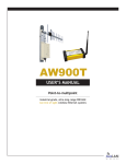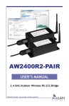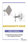
1
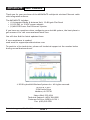
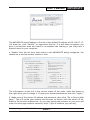
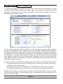
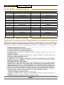
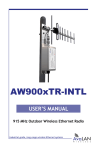
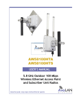
AW2400xTP USER’S MANUAL 2.4 GHz Integrated Radio & Antenna Industrial-grade, long-range wireless Ethernet systems AvaLAN W I R E L E S S AW900XTP AW2400xTP User’s Manual Thank you for your purchase of the AW2400xTP multipoint wireless Ethernet radio with integrated antenna. The AW2400xTP includes: • (1) Integrated Radio & Antenna Unit, 19 dBi gain Flat Panel • (1) 120 VAC to 12 VDC power adapter • (1) AW-POE Power Over Ethernet Injector If you have any questions when configuring your AvaLAN system, the best place to get answers is to visit www.avalanwireless.com. You will also find the latest updates there. If more assistance is needed, send email to [email protected]. To speak to a live technician, please call technical support at the number below during normal business hours. © 2010 by AvaLAN Wireless Systems Inc. All rights reserved. Revision 08.17.2010 125A Castle Drive Madison, AL 35758 Sales: (866) 533-6216 Technical Support: (650) 384-0000 Customer Service: (650) 641-3011 Fax: (650) 249-3591 Technical support (650) 384-0000 PAGE 2 www.avalanwireless.com User’s Manual AW2400xTP Operational summary The AW2400xTP Integrated Radio & Antenna allows the user to create a long-range, wireless Ethernet network with up to 16 Subscriber Units per Access Point. The configuration may include any combination of AW2400xTR, AW2400iTR and AW2400xTP radios. Configuring a wireless link with the AW2400xTP requires the establishment of six elements: • Each radio must know whether it is to be an Access Point (AP) or Subscriber Unit (SU). • Each radio must have an IP address that is unique among all others on the same network. • The AP must know how many SUs are expecting communication with it. • The AP and any given SU must agree on which radio frequency channel they are using. This can be manually set or allowed to change automatically. • The SU must be assigned a unique subscriber ID to specify which time division slot it will use when communicating with the AP. • The AP and any given SU must share a common 128-bit encryption key. APs can exchange keys with up to 63 SUs, though only 16 can be connected at any given time. The AP automatically scans for the best of the 37 available radio frequency channels, encrypts Ethernet data received from the network, and transmits it wirelessly to the correct SU. The AP is constantly monitoring the radio link and can automatically change the channel if performance is degraded due to interference. If two AP units are physically close to one another, they may interfere if operating on adjacent frequency channels. Place them at least 10 feet apart or manually select non-adjacent channels for their operation. Also, the SU should be placed at least 10 feet from the AP to avoid overloading the receivers. Any 10/100 BaseT Ethernet client device (ECD) can be connected to an AW2400xTP Subscriber Unit. Each SU encrypts Ethernet traffic received from the attached ECD and transmits the data wirelessly to its AP. Each SU can be plugged directly into an ECD without adding drivers or loading software. Essentially, once the AP/SU pair is configured and running it behaves like a continuous Ethernet cable. Technical support (650) 384-0000 PAGE 3 www.avalanwireless.com AW900XTP AW2400xTP User’s Manual Physical Setup 1. Before mounting the radio in its final location, you may want to perform the digital setup procedure described in the next section. 2. Mount the AW2400xTP securely using the mounting bracket provided or other means as necessary. Maximize lightning resistance by providing a strong DC ground connection to the metal housing. 3. The unit may be mounted with horizontal or vertical polarization and it is important that the antenna of the Access Point and the antenna of the Subscriber Unit be pointed toward one another and be oriented with the same polarization. Use care in aiming because the antenna beam width is only about 10º. In a point-to-multipoint situation with radially dispersed SUs, you should use an AW2400xTR equipped with an omnidirectional antenna as the Access Point. 4. Power is provided to the unit by means of the Ethernet cable, allowing the power supply to be located at a convenient location. The included power-over-Ethernet injector (POE) provides the means for adding DC power to unused wires in the cable. Decide where to place the POE based on proximity to AC power at some point along the desired path of the Ethernet cable. Plug the included power supply into an appropriate electrical outlet and into the POE. Connect an Ethernet cable between your network and the “DATA IN” port on the POE. Connect a second cable from the “P + DATA OUT” port on the POE and the AW2400xTP. The AW2400xTP is provided with a cable clamping device that allows an RJ45 plug on the cable to pass through it and can be tightened down around the cable to provide a weatherproof seal. Digital Setup 1. Digital configuration is done by means of the AW2400xTP’s built in browser interface. It should be powered on and connected at least temporarily to a network containing a computer that can run a conventional web browser. 2. Download the AvaLAN IP Discovery Utility from our website and extract ipfinder.exe from the zip archive, placing it on your desktop or in a convenient folder. http://www.avalanwireless.com/ipfinder/ipfinder.zip Note that this utility only runs on MS Windows, not linux or MAC. If you must use a non-Windows computer for configuration, make sure your subnet mask allows your computer to see 192.168.17.17. Connect to that default IP address with your web browser, continuing the setup procedure with step 6. 3. Run the IP Discovery Utility, ipfinder.exe and you should see a window similar to the view on the next page. Technical support (650) 384-0000 PAGE 4 www.avalanwireless.com User’s Manual AW2400xTP The AW2400xTP should appear in the list at the default IP address of 192.168.17.17. If it does not, click “Search” to regenerate the list. If it still does not appear, you have a connection issue and need to re-examine the cabling or you may have a firewall issue on your computer. 4. Double click the list item that refers to the AW2400xTP being configured. You should see a second window similar to this: The information on the left is the current status of the radio, while the boxes on the right allow you to change it. Choose your desired parameters and click “Apply.” 5. Make note of the chosen IP address and password, then click “Go to Device Web Page.” This will cause your default web browser to launch with the device IP address in the browser address bar. Or you may launch the browser on your own and enter the web page address manually: http://[the IP address you just set]. Technical support (650) 384-0000 PAGE 5 www.avalanwireless.com AW900XTP AW2400xTP User’s Manual 6. The browser page that loads first shows the current device information and QoS statistics and provides a login at the upper right. Log in using the password you just specified (or “password” if you kept the default). If the login succeeds, you will see an admin page similar to this: 7. The admin page has sections similar to the login page showing radio statistics and device information plus it adds several new sections. The Device Settings section allows setting the network information and choosing an RF frequency channel. The default is to allow the radio to choose its own frequency based on minimizing interference. If you set a fixed channel, make sure the AP and all SUs use the same one. References to DIPs on this and the next web page refer to switches inside the radio that are used in the legacy method of configuration and may be ignored when using the browser method. If you scroll down in the Admin browser page, you will come to three more sections: • A graphical spectrum analyzer display that may help you to select radio channels that avoid interference • A section to be used if an update to the AW2400xTP’s firmware is required • An Advanced Links section with a dire warning about advanced users only. Despite the warning, you will need to click the “Advanced Admin” button in order to set the device type, ID and encryption key. You should then see a page similar to that on the next page. Technical support (650) 384-0000 PAGE 6 www.avalanwireless.com User’s Manual AW2400xTP 8. On the Advanced Admin page, set the parameters as follows: • Choose Device Type: Access Point or Subscriber Unit. • For Subscriber Units, assign unique ID numbers in numeric order from 1 to 63. • For an Access Point, enter the number of Subscriber Units that will be communicating with it. • Click the box labeled “Enable User Specified Keys.” • Choose an 8-digit hex (0-9 and A-F) Network Name that will be common among the AP and its SUs and enter it. The hyphen is required. • Choose a 32-digit hex encryption key and enter it. Again, the hyphens are required. This key must match between the AP and the SU so make a note of it as well. After entering the parameters, click the “Apply” button to save them to the radio. 9. When all of the radios are keyed and operating, connect them to your network and Ethernet devices as desired and cycle the radio’s power to begin normal operation. Now, browser mamagement of the SUs can be performed over the wireless network. Note: avoid plugging actively linked radios into the same switch because this will corrupt its routing table and may cause network problems just as if you had plugged a CAT5 cable directly between two ports of a switch. Technical support (650) 384-0000 PAGE 7 www.avalanwireless.com AW900XTP AW2400xTP User’s Manual 2.4 GHz Channels Channel 0 1 2 3 4 5 6 7 8 9 10 11 12 13 14 15 16 17 18 Center Frequency Auto Mode 2.404167 GHz 2.406250 GHz 2.408333 GHz 2.410417 GHz 2.412500 GHz 2.414583 GHz 2.416667 GHz 2.418750 GHz 2.420833 GHz 2.422917 GHz 2.425000 GHz 2.427083 GHz 2.429167 GHz 2.431250 GHz 2.433333 GHz 2.435417 GHz 2.437500 GHz 2.439583 GHz Channel 19 20 21 22 23 24 25 26 27 28 29 30 31 32 33 34 35 36 37 Center Frequency 2.441667 GHz 2.443750 GHz 2.445833 GHz 2.447917 GHz 2.450000 GHz 2.452083 GHz 2.454167 GHz 2.456250 GHz 2.458333 GHz 2.460417 GHz 2.462500 GHz 2.464583 GHz 2.466667 GHz 2.468750 GHz 2.470833 GHz 2.472917 GHz 2.475000 GHz 2.477083 GHz 2.479167 GHz Limited Warranty This product is warranted to the original purchaser for normal use for a period of 360 days from the date of purchase. If a defect covered under this warranty occurs, AvaLAN will repair or replace the defective part, at its option, at no cost. This warranty does not cover defects resulting from misuse or modification of the product. Technical support (650) 384-0000 PAGE 8 www.avalanwireless.com