1
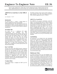
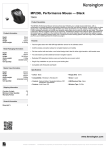
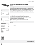
1
Rev 1.0 May 2012
Integriti
Colour Graphic Terminal
Part Number: 996000 / 996000B
Installation Manual
The Integriti Colour Graphic Terminal is a User interface for the Integriti Hardware
platform. It features eight status LEDs, a full colour LCD screen, built-in temperature
sensor, easy to read text, and icon, scroll wheel and function key based navigation system.
The colour and intensity of the Keypad backlighting and Screen colour schemes are
configurable and feature auto-dimming.
Audible indications are provided by sophisticated 8-bit digital sound tones and options
are provided for Date/Time and Temperature on the default display.
Graphic Terminals can be used in systems to perform programming, commissioning and
User operations, display alarm messages and review system activity. They communicate
on the LAN as a Graphic Terminal Module Type, and the module number and
configuration options are programmed from the keypad. Built-in tamper monitoring
detects any attempt to open the case or remove the product from the mounting surface.
Specifications
Power Supply Input:
Operational Current:
Default Backlight settings:
11V to 14V DC
Physical dimensions:
Height: 162mm
Width: 88mm
Depth: 15mm
Polycarbonate
0º - 40º C @15% to 85% relative humidity
(non condensing)
Low Ambient Light: Approx. 55mA.
High Ambient Light: Approx. 75mA.
Custom Backlight settings: 50mA to 180mA.
Beeper Operating:
Add up to 65mA at maximum speaker volume
level.
Enclosure material:
Installation environment:
©
2012. Inner Range Pty. Ltd.
Part No: 636000
2
Integriti Colour Graphic Terminal Installation Manual.
Mounting template
132.5 mm
Position of
LCD Display
14mm
85.5 mm
Legend:
= Rear Casing mounting holes
= Tamper Lever mounting hole
Cable entry cutout
27.5 mm
25.5 mm
158 mm
47 mm
88 mm
27.5 mm
55 mm
Rev 1.0 May 2012
3
Installing the Terminal
Colour Graphic Terminal Parts List
- Colour Graphic Terminal assembly.
- Installation Manual and mounting template. (This document)
Installation
1. Choose an appropriate mounting location with a solid, flat, vertical surface and ensure
that the LCD display will be at, or slightly below eye level for all users.
2. a) Remove the rear of the case by first applying gentle pressure to the lower locking tabs
in the bottom rear of the case with a small flat-blade screwdriver, while gently pulling the
lower front of the case away from the rear.
b) Then gently pull one side of the front case away from the rear to release the upper
locking tabs.
3. Check that the mounting surface is free from any materials or irregularities which may
distort the case, then mark the mounting hole locations. Remember to insert the LAN
cable and any other wiring through the cable entry cutout before fastening the rear casing
to the mounting surface.
Refer to Installation template supplied opposite.
4. Install the rear casing using three countersunk screws or bolts.
The Tamper Switch actuating lever may also be fastened to the mounting surface to provide
an enhanced level of cabinet tamper detection. Do not overtighten, as this may cause the
lever to dig into the mounting surface and limit its ability to actuate the Tamper Switch.
5. Connect the wiring into the Screw Terminal block. See pages 4 & 5 for details.
6. Position the three tabs at the top of the front casing into the slots at the top of the rear
casing, then gently press the two halves together until the locking tabs on the sides and at
the bottom of the case engage.
4
Integriti Colour Graphic Terminal Installation Manual.
Connections
CAUTION !.
Take care not to damage PCB tracks, the components around the Screw
Terminals or the LED light pipes at the top of the unit during installation.
LED Light Pipes
TERM (Not Fitted)
This link must NOT be
fitted on an Integriti
Colour Graphic
Terminal.
ETX / ERX
Connection for field
firmware upgrades
and future expansion
board.
LAN Connections.
See following page for
information.
5
Rev 1.0 May 2012
LAN Wiring
The LAN is connected using twisted pair
communications cable. Connect LAN A &
LAN B using one pair; LAN+ & 0V with
another pair. A & B must be on the same pair.
(Over longer distances, use heavy duty Figure
8 cable for LAN+ & 0V, or use a separate local
power supply)
Cabling distance should be no more than
1.5km from the Control Module, a LAN
Isolator “LAN 2 or 3” Port, or a Fibre Modem
RS485 Port.
LAN+ 0V LANA LANB ETX ERX
*
+ - A B
* LAN+ not connected if
Terminal powered from
external Power supply.
+ -
A B
To next
module
From
Previous
module
Auxiliaries and LEDs
There are no physical Auxiliary outputs available on a Graphic Terminal.
Auxiliaries are used for the following indicator control functions:
G??:X01
G??:X02
G??:X03
G??:X04
G??:X05
G??:X06
G??:X07
G??:X08
Aux. 1:
Aux. 2:
Aux. 3:
Aux. 4:
Aux. 5:
Aux. 6:
Aux. 7:
Aux. 8:
Not currently used.
Not currently used.
Not currently used.
Not currently used.
Not currently used.
Not currently used.
Not currently used.
Not currently used.
G??:X09
G??:X10
G??:X11
G??:X12
G??:X13
G??:X14
G??:X15
G??:X16
Aux. 9:
Aux. 10:
Aux. 11:
Aux. 12:
Aux. 13:
Aux. 14:
Aux. 15:
Aux. 16:
LED 1.*
LED 2.*
LED 3.*
LED 4.*
LED 5.*
LED 6.*
LED 7.*
LED 8.*
* Note: Graphic Terminal programming “LED Mode” option must be set to “Auxiliary”.
LED Number: 1
2
3
4
5
6
7
8
6
Integriti Colour Graphic Terminal Installation Manual.
Access Control via a Graphic Terminal
At present, the Graphic Terminal can be used for Door Access Control in “PIN Only”,
“PIN or Card” or “Card & PIN” modes to provide the PIN code entry.
However, the following conditions currently apply:
1) The Graphic Terminal does not currently support any Inputs or Outputs. Therefore,
the Door must also be associated with a Reader Module, and all Inputs and Outputs
associated with the Door must be connected to that Reader Module.
2) The Lock Auxiliary for the Door must be the Reader Module Lock Auxiliary, not the
Terminal Lock Auxiliary.
Commissioning
When installation is complete, power up the Terminal.
The startup screen will display “Waiting for LAN Connection” along with the Module
number, Firmware Version, and a <Config> Function key. This screen is displayed for:
- 30 seconds or until <Config> or <END> is pressed if Tamper switch is unsealed.
- 2.5 seconds if the Tamper Switch is sealed.
• To view and/or change the Module Number (Set to 01 at the factory) or the Colour
Scheme, press the <Config> Function key while this initial screen is displayed, then
go to “Colour Scheme and Terminal Number” below.
• To exit the startup screen and go to the normal default display, press the <END> key.
If the “Waiting for LAN Connection” message is shown for more than 30 seconds, the
Module has not enrolled on the LAN. This could be due to:
- A LAN cabling and/or connection problem.
- Another Graphic Terminal with the same Module Number is already enrolled.
- The number of Modules on the LAN exceeds the limits of the Memory Configuration or
the licensing for this Control Module.
When the startup screen closes, the display may show a Terminal message, Time/Date,
Area status, or Alarm message, etc. This means the Module Number has been accepted.
To change the Module number or Colour scheme you will need to enter the Configuration
mode as described above.
To change other Graphic Terminal parameters, you will need to enter Setup mode as
described in “Graphic Terminal Setup” below.
Colour Scheme and Terminal Number.
a) Enter Configuration mode as described above.
b) To change the colour scheme, press the <Colour> Function key.
b) To change the Module Number, choose a number that isn’t already used by another
Rev 1.0 May 2012
7
Graphic Terminal and enter the new number using the <DIGIT> keys. Use the
<Delete> Function key to backspace if you make an error. Press <OK> to save the
new Module number.
c) Press <Exit> when complete.
Graphic Terminal Setup.
1. Enter Setup Mode.
Logon with the Installer PIN code, press <MENU>, then “Setup” (7 key), then
“Terminal” (1 key).
At any time, the following keys (if displayed) may be used:
<Back> function key: Scrolls back through the configuration screens.
<More> function key: Scrolls forward through the configuration screens.
<END> key:
Exits config and returns to the normal display.
2. Terminal Setup options. 2 screens.
a) Use the <UP> & <DOWN> Arrows or Scrollwheel to select the option to change.
b) Press <ON> to enable, or <OFF> to disable the check-box type option.
c) The <LEFT> & <RIGHT> Arrows can be used to change the Colour Scheme.
d) If changes are made, press <OK> to save the changes and step to the next screen.
2.1 Audio, RFID (future enhancement) & Custom Keypad Colour options.
• Audio auto-off. The speaker is muted when no audio is present, to eliminate
background noise. This may be preferred in quiet areas e.g. bedrooms. If enabled,
a short delay may occur between the re-appearance of an audio signal, and the
speaker being un-muted.
• Enable RFID ASK support. (Not yet available)
• Enable RFID HID support. (Not yet available)
• Enable custom keypad RGB. (If enabled, adjust the RGB values in Step 3.2)
2.2 Keypress options & Factory reset.
• Enable red flash on error.
• Enable keypress flash.
• Reset all to factory defaults.
3. Terminal Preferences. 4 screens.
a) Use the <UP> and <DOWN> Arrows to select the setting to change.
b) Use the SCROLL WHEEL to change a level setting, <ON>/<OFF> for check-box
options.
c) If changes are made, press <OK> to save the changes and step to the next screen.
8
Integriti Colour Graphic Terminal Installation Manual.
3.1 Speaker, LCD Backlight and LED level options.
• Speaker Volume level.
• LCD Minimum Backlight level. (In very low ambient light. e.g. A dark room)
• Indicator LED Minimum and Maximum levels.
3.2 Keypad Backlight Levels.
• Keypad Minimum Backlight level. (In very low ambient light. e.g. A dark room)
• Custom Keypad Red, Green and Blue levels. NOTE: These settings only relevant
if the “Enable custom keypad RGB” option is enabled at Step 2.1.
3.3 Keypad Colour Mode.
None / Rainbow (fast) / Rainbow (slow) / Flame / Water / Random.
3.4 Keypad Sensitivity.
Key sensitivity. Use the <DIGIT> keys to test while making adjustments.
Scrollwheel sensitivity. Use <4> and <6> keys to adjust, and the Scrollwheel to test
while making adjustments. Use the <2> key to go back to Key Sensitivity adjustment.
4. Resource configuration information.
The Integriti Graphic Terminal can have alternative sets of Image, Sound, Text String
and Font resources. At any given time, one of each of these resources is in use in the
device.
The Resource Configuration screen allows the Installer to view the “Currently Loaded
Resources” files (currently in use).
- String and Font files will cater for different languages as they become available.
- Image files will provide alternative sets of bitmaps, icons and colour schemes.
- Sounds files will provide alternative sets of sound effects.
At the time of writing this manual, no additional resource files are available for the
Integriti Graphic Terminal.
5. Additional Graphic Terminal programming.
Other options are programmed in “Graphic Terminal Programming”, <MENU>, 7, 2, 5.
See the Integriti Software Help or the latest version of the Integriti Programmer’s manual
for details.
Also refer to the Integriti Graphic Terminal User Manual for additional information on
the default display, Iconic and Text menu displays and the various Graphic screens for
control, information and programming operations.