1
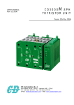
CD3200
USER’S MANUAL
Rev. 03/2006
THYRISTOR UNIT
from 15A to 110A
CD Automation S.r.l.
Via Picasso 34/36 - 20025 – Legnano (MI) – ITALY
Tel +39 0331 577479 – Fax +39 0331 579479
E-Mail: [email protected] - WEB: www.cdautomation.com
INDEX
1 Warnings .......................................................................................................................5
1.1 Important warning for safety
5
2 Introduction ..................................................................................................................7
2.1
2.2
2.3
2.4
Advantages compared with analog thyristor unit.
CD-KP high lights
Clone facility using CD-EASY
Software Configurator
7
8
9
10
3 Quick Start .................................................................................................................. 11
4 CD3200 Sizing ............................................................................................................. 11
5 Identification and Product Code .................................................................................. 12
5.1 Identification of the unit
5.2 Ordering code
12
13
6 Installation .................................................................................................................. 14
6.1
6.2
6.3
6.4
6.5
Environmental installation conditions
Dimensions
CT dimensions
Fixing holes
Removing the cover
14
15
15
16
16
7 Wiring instructions ...................................................................................................... 17
7.1
7.2
7.3
7.4
7.5
7.6
7.7
Wiring details
Power Terminals
Auxiliary Terminals
Diagram of control connection
Diagram of control connection
Diagram of control connection
Diagram of control connection
from size 15A to 25A
from size 35A to 45A
from size 60A to 90A
for size 110A
17
19
19
20
21
22
23
8 Technical features ....................................................................................................... 24
8.1 Power output features
8.2 Derating curve
8.3 Cooling fans
24
24
24
9 Led status and alarms.................................................................................................. 25
9.1 LED Status Table
9.2 Events and alerts that don’t stop CD3200
9.3 Heater break alarm and scr short circuit (HB Option)
25
25
25
10 Types of firing mode .................................................................................................. 27
10.1 Soft Start + Phase Angle (S+PA)
10.2 Phase Angle (PA)
10.3 Feed-back ( control mode )
27
27
29
3
CD Automation srl
CD3200
User’s Manual from 15A to 110A
11 Connection description .............................................................................................. 30
11.1
11.2
11.3
11.4
11.5
11.6
11.7
Electronic boards
Auxiliary power supply connections
Analog inputs
Digital Input
RS485 serial connection
PG Connector
Address configuration
30
31
32
35
36
36
37
12 Fuses and Fuse holder ............................................................................................... 38
12.1 Fuses and Fuse Code for UL
12.2 Fuses and Fuse Code for CE
12.3 FuseHolder size
38
39
40
13 Modbus communication ............................................................................................. 41
13.1
13.2
13.3
13.4
13.5
13.6
13.7
Physical requirements
Modbus Rtu Protocol
Message formats
Read holding registers (read n words) – Function 03
Preset multiple registers (write n words) - Function 16
Error and exception responses
Modbus parameters
41
41
41
44
44
45
46
14 Maintenance .............................................................................................................. 50
14.1
14.2
14.3
14.4
14.5
Trouble Shooting
Fans
Servicing
Repairing procedure
Warranty condition
50
51
51
51
51
15 CD Automation’s distributors..................................................................................... 52
16 Note .......................................................................................................................... 54
4
CD Automation srl
CD3200
User’s Manual from 15A to 110A
1 Warnings
1.1 Important warning for safety
This chapter contain instruction about safety. The non observation of these warnings can cause
serious accident and the loss of life of operator. Serious damages can be also caused to the
thyristor unit and to the component system in which is included.
The installation must be done by qualified people.
In manual description are used following icons.
Hazard: This icon is present in all operative procedure where if non executed properly
can cause serious accident and loss of life of the operator.
Attention: This icon is present in all operative procedure where if not executed
can cause faults to the thyristor unit.
Thyristor units are used in power industrial equipment. When the thyristor unit is
working there are on the unit the following voltages.
•
Maximum main supply voltage on power terminals up to 600 V.
•
Auxiliary supply up to 690 Vac (see order code)
•
Fan voltage 230Vac 50/60Hz (110V optional)
Don't remove the cover which provides adequate protection against electric shock.
Don't use this thyristor unit in aerospace and nuclear application.
Electric Shock Hazard (Risque the choque électrique)
When thyristor unit has been connected to main supply voltage and is switched off,
before to touch it be secure that the unit is isolated and wait at least one minute to
allow discharging internal capacitors. Thus be secure that:
•
access to thyristor unit is only permitted to specialized personnel;
•
the authorized personnel must read this manual before to have access to the unit;
•
the access to the units must be denied to unauthorized personnel.
Important warnings(attention)
Local regulations regarding electrical installation should be rigidly observed.
•
Safety regulations must be rigidly observed.
•
Don't bend components to maintain insulation distances.
•
Protect the units from high temperature humidity and vibrations (see
performances).
•
Don't touch components to prevent electrostatic discharges on them.
•
Verify that all rating are in line with real needs.
•
If authorized personnel must measure voltage current etc. on units, take away
rings and other jewels from fingers and hands.
•
Authorized personnel working on thyristor unit under power supply voltage must
work on insulated board. Be secure that board is not connected to earth.
This listing does not represent a complete enumeration of all necessary safety
cautions.
5
CD Automation srl
CD3200
User’s Manual from 15A to 110A
Protection(protection)
CD3200 thyristor unit has an insulated cover to compliance to International
specification IP20. To understand if IP20 protection is sufficient should be evaluated
the installation place where the units are installed
Earth(terre)
CD3200 family has isolated heatsink. For safety connect the heatsink to earth to avoid
shocks in case that circuit board or THYRISTOR lose insulation. Earth impedance
should be correspondent to local earth regulation. Periodically the earth efficiency
should be inspected.
Electronic supply (alimentation électronique)
CD3000 family electronic circuit should be supplied by dedicated voltage supply for all
electronic circuit but not in parallel with contactor’s coil, solenoids and other inductive
or capacitive loads. It’s recommended to use a shielded transformer.
Electromagnetic compatibility (compatibilité électromagnétique)
Our thyristor units have an excellent immunity to electromagnetic interferences if all
suggestions contained in this manual are respected. In respect to a good Engineering
practice, all inductive loads like solenoids contactor coils should have a filter in parallel.
Emissions (emission)
All thyristor switching at high speed generate some radiofrequency disturbance.
CD3200 series compliance with EMC rules for CE mark. In many installations near
electronic devices have not been noted problems. If radiofrequency devices at low
frequency are used near the thyristor unit some precautions should be taken like line
Filters and shielded cables for input signal and for load cables.
NOTES
We reserves the right to apply modifications to the our products without any advice.
The thyristor unit must be mounted vertically and with no obstruction above and below
to allow good flow ventilation.
When mounted side by side leave a gap of 15 mm between the units.
Hot air of one thyristor unit must not invest the unit positioned above.
The maximum cabinet temperature must not exceed 40°C.
A suitable electromechanical device must ensure that the unit can be electrically
isolated from the incoming line supply.
C
UL
®
US
LISTED
6
CD Automation srl
CD3200
User’s Manual from 15A to 110A
2 Introduction
A thyristor unit is semiconductor device which acts as a switch formed by two thyristors in ant
parallel. To switch on the alternating current the input signal will be on and the thyristor will switch
off at first Zero Crossing voltage with no input signal. The benefits of thyristor units compared with
elettromechanical contactors are numerouses: no moving parts, no maintenance and capacity to
switch very fast. Thyristors are the only solution to control transformers and special loads that
change resistance with temperature and with age.
Thyristor
Load
2.1 Advantages compared with analog thyristor unit.
CD3200 can be connected via RS485 to an Industrial Personal Computer.
On serial link are available many information like: current, power, load status and all the
parameters for diagnostic and configuration. Tele service and clone facility is also available.
The advantages over the analog and non “Full digital” versions are flexibility and the possibility to
implement special features without to change any Hardware.
Several strategies can be implemented and selected via the parameter on serial link.
All these features are not available on analog thyristor unit that use also small micro just to
perform dedicated task (Ex. for Heater Break Alarm).
7
CD Automation srl
CD3200
User’s Manual from 15A to 110A
On CD Automation web-site is available, free of charge, the Configuration Software.
A cable with its built in converter and connector is available from CD Automation.
The configuration cable can be plugged into the PG connector of CD3200, or if a CD-KP is available
it’s possible to have the connection above indicated on front unit.
This solution allow to engineers to verify configuration without to go inside the cubicle where there
is high voltage and without to stop the plant.
2.2 CD-KP high lights
2.2.1 General description
•
Local/remote facility
•
Set point ramp up/down
•
Scroll selection of:
-Set point power
-Power read out
-Current
•
Display indication for:
-Heater Break Alarm
-SCR short circuit
•
Retransmission (4-20mA or 0-10V selectable)
of one of these parameters: power, current.
•
Dimensions 48x96x92mm (WxHxD)
CD-KP is designed to give two access levels.
•
First Level Access: the operator is able to view the power, current and voltage as well as set
the power when the CD-KP is in Local Mode.
At this level the password function is disabled to prevent accidental parameter changes by
unauthorized personnel.
•
Second level access: By connecting a PC to the RS232 port, located on the front of the CD-KP,
it’s possible to have access to all parameters of the CD Automation Thyristor Unit using the
free downloadable Configuration Software.
Configuration changes can be made interactively, without powering down the unit, removing
the need to open the cabinet or to stop the process.
8
CD Automation srl
CD3200
User’s Manual from 15A to 110A
2.3 Clone facility using CD-EASY
CD-EASY is a Memory Support used by maintenance personnel in the shop floor.
The Clone Facility makes it possible to copy the configuration of one Thyristor Unit and paste it into
another in a matter of seconds. The CD-EASY can be loaded with the standard unit operating
configuration and stored together with the system drawings in a convenient place, enabling unit
reconfiguration within seconds if required.
For CD-KP and CD-EASY are available Maintenance Manuals on www.cdautomation.com.
9
CD Automation srl
CD3200
User’s Manual from 15A to 110A
2.4 Software Configurator
You can download the free software
Configurator from our web site.
www.cdautomation.com
If the CD3200 code is in line with your
requirement, providing that the operating
voltage and Load current are inside the
code the CD3200 has been already
configured in our Factory and you are
ready to run.
You need software tools only to modify
the ordered configuration. Anyway we
suggest checking the unit on the machine
with the test section.
To install the software download it from
the website, launch the installation
program and follow the instruction on the
screen.
To configure the unit you can use the
standard communication port RS485 on
terminals blocks or use the programming
Cable and plug it inside the PG connector.
(see par. 11.6)
Connect the other side of the
programming cable to the PC
RS232(9PIN) serial port.
Set the baud (=9600) and address
(default=1) of PC serial port.
10
CD Automation srl
CD3200
User’s Manual from 15A to 110A
3 Quick Start
Attention: this procedure must be carried out by skilled people only.
If your CD3200 code is in line with what you really need, then the main configuration is already
done by CD Automation and you just need to do the following steps:
1. Verify CD3200’s current sizing. Be sure that:
•
the load current is equal or less than the nominal one of CD3200
•
the main voltage is equal or less than the nominal voltage of CD3200
2. Verify the Product code
3. Verify the Installation
4. Verify the Wiring:
•
all auxiliary connections must be done in line with wirings on this manual
•
verify that there isn’t a short circuit on the load
•
verify that the Reset Contact on terminal 3 and 4 are closed
•
With External Enable option give Enable to the unit
5. Supply the auxiliary voltage of the unit
6. Supply the Fan at 230VAC ±15% 50/60Hz (110VAC ±15% 50/60Hz Optional)
(Only for size 110A)
7. Supply the Power unit
1. Makes Calibration procedure (see par. 10.2.2)
If your CD3200 code is NOT in line with what you really need, use the configurator
software tool to set-up the unit.
4 CD3200 Sizing
4.1.1 Wiring with resistive load
I=
P
V
V = Nominal voltage phase to phase
I = CD3200 Nominal current
P = Nominal power to the load
4.1.2 Wiring with inductive load
I=
P
V cos φ
V = Nominal voltage phase to phase
I = CD3200 Nominal current
P = Nominal power to the load
11
CD Automation srl
CD3200
User’s Manual from 15A to 110A
5 Identification and Product Code
5.1 Identification of the unit
Before to install the CD3200 unit examine for damages or deficiencies. If any is
found, notify the carrier immediately. Check that the product features shown on
CD3200 identification label corresponds to that ordered (see par.5.2)
An identification label provides all the information regarding the factory settings of the unit.
This label is on the unit, as represented below:
Identification Label
identificazione
12
CD Automation srl
CD3200
User’s Manual from 15A to 110A
5.2 Ordering code
Model CD3200
CD3200
Ex:CD3200
1
2
3
4
5
6
7
8
9
75A
75A
400V
480V
90:130V
0÷10V
PA
V
HB
1
Max CURRENT of CD3200
15A
35A
60A
110A
25A
45A
90A
The Max CURRENT must be equal or more than nominal current
2
Load CURRENT
Specify this value that will be used to configure the unit in CD Automation
3
Load Voltage(incoming voltage supply)
Specify this value that will be used to configure the unit in CD Automation
4
Max VOLTAGE of CD3200
480V
600V
The Max VOLTAGE must be equal or more than operating voltage
5
Auxiliary Voltage
90:130V Da 90 a 130Vac; 10VA
170:265V Da 170 a 265Vac; 10VA
230:345V Da 230 a 345Vac; 10VA
300:530V Da 300 a 530Vac; 10VA
510:690V Da 510 a 690Vac; 10VA
6
Input
0÷10V
0÷10Vdc
4÷20mA 4÷20mA
POT
10KΩ potentiometer
V2
VxI
Voltage square
Power (VxI)
7
Firing
S+PA
Soft Start + Phase Angle
PA
Phase Angle
8
V
I
Feed Back
Voltage
Current
9
Options
COMM
MODBUS protocol in RS485 is standard
CD-KP
External Keypad
EF
External fuses and fuse holders
NF
No fuses
NCL
No current limit
CLP
External current limit profiling 0-10Vdc
EN
Opto isolated external enable
HB
Heater Break Alarm
FAN110
Fan voltage supply 110VAC ± 15%
(std 230VAC ± 15%) 14W 50/60Hz
EP
External Protection IP20 for size S7C and S8C
CD-EASY Clone facility & memory card
UL
UL Certification
13
CD Automation srl
CD3200
User’s Manual from 15A to 110A
6 Installation
CD3200 unit should be always mounted in vertical position to improve air cooling on
heatsink. Maintain minimum distances in vertical and in horizontal as below
represented. Don’t install in proximity of hot elements and near units generating
electromagnetic interferences.
When many units are mounted inside a cubicle provide air circulation as below represented.
Sometimes it is necessary to provide a fan to have better air circulation.
6.1 Environmental installation conditions
Ambient temperature
0-40°C at nominal current. Over 40°C use the
derating curve (par.8.2)
Stocking temperature
-25°C to 70°C
Installation place
Altitude
Humidity
Don’t install at direct sun light, where there
are conductive dust, corrosive gas, vibration or
water and also in salty environmental
Up to 1000 meter over sea level. For higher
altitude reduce the nominal current of 2% for
each 100m over 1000m
From 5 to 95% without condense and ice
14
CD Automation srl
CD3200
User’s Manual from 15A to 110A
6.2 Dimensions
CD3200
15A÷25A (S0C)
CD3200
35A÷45A (S3C)
H
H
D
W
CD3200
60A÷90A (S7C)
CD3200
110A (S8C)
H
D
H
D
W
W
D
W
Size
W(mm)
H(mm)
D(mm)
15A (S0C)
63
120
120
25A (S0C)
63
120
120
35A (S3C)
85
120
120
45A (S3C)
85
120
120
60A (S7C)
148
120
159
90A (S7C)
148
120
159
110A (S8C)
148
138
159
6.3 CT dimensions
39
12
8
39
20
15
CD Automation srl
CD3200
User’s Manual from 15A to 110A
6.4 Fixing holes
B
C
B
Size
A(mm)
B(mm)
C(mm)
15A (S0C)
110
30
-
25A (S0C)
110
30
-
35A (S3C)
110
40
-
45A (S3C)
110
40
-
60A (S7C)
110
40
65
90A (S7C)
110
40
65
110A (S8C)
110
40
65
B
6.5 Removing the cover
Remove plastic Cover For all size
To remove the board Pull the PCB
16
CD Automation srl
CD3200
User’s Manual from 15A to 110A
7 Wiring instructions
Warning: this procedure can be done just by specialized personnel
CD3200 unit has isolated heatsink. For safety connect the heatsink to hearth using its
terminal with hearth symbol.
CD3200 can be susceptible to airborne interferences from near equipment or from interferences on
main supply, so a number of precautions must be taken.
•
Contactors coils and chokes must have in parallel a RC filter and must be supplied with a
different voltage line.
•
All input/output signals must use screened bifilar wires.
•
Signal input and output must not route in same cable try and must not be parallel.
•
Local regulations regarding electrical installation should be rigidly observed.
7.1 Wiring details
Use copper cables and wires rated for use at 75 °C only, provided with the terminal type indicated
below.
7.1.1 Power cable torque (suggested)
Current
Connector
Type
Torque
Lb-in (N-m)
Wire
Range
AWG / kcmill
Wire
Terminal
15A, 25A,
35A, 45A
M5 Screw
26.6 (3.0)
8
UL Listed (ZMVV)
Wire Pin
60A, 90A,
110A
M6 Screw
70.8 (8.0)
1
UL Listed (ZMVV)
Fork/Spade Terminal
Copper Tube Crimp. Lug
17
CD Automation srl
CD3200
User’s Manual from 15A to 110A
7.1.2 Power cable dimensions (suggested)
Current
Supply
Load
Screw
Cable
Screw
Cable
mm2
AWG
M
mm2
AWG
M
15A
4
12
M5
4
12
M5
25A
6
10
M5
6
10
M5
35A
10
8
M5
10
8
M5
45A
10
8
M5
10
8
M5
60A
16
6
M6
16
6
M6
90A
35
3
M6
35
3
M6
110A
35
3
M6
35
3
M6
7.1.3 Auxiliary cable dimensions (suggested)
Current
Auxiliary Supply
Earth
Cable
Cable
Screw
mm2
AWG
mm2
AWG
M
15A
0,50
18
4
12
M5
25A
0,50
18
6
10
M5
35A
0,50
18
6
10
M5
45A
0,50
18
6
10
M5
60A
0,50
18
6
10
M5
90A
0,50
18
6
10
M5
110A
0,50
18
6
10
M5
18
CD Automation srl
CD3200
User’s Manual from 15A to 110A
7.2 Power Terminals
Before to connect or disconnect, make sure that power cables and auxiliary wires are
insulated from live voltage.
Terminal
L1
T1
Description
Line Input Phase 1
Load Output Phase 1
7.3 Auxiliary Terminals
7.3.1 Upper Terminal
Terminal
1
2
3
4
5
6
A2+
A1-
Description
(-) External Calibration 24 Vdc max
(+) External Calibration 24 Vdc max
Reset
Reset
(+) CD3200 Output Command signal (Internal Connections)
(-) CD3200 Output Command signal (Internal Connections)
(+) Input command signal 0÷10V,4÷20mA,POT
(-) Input command signal 0÷10V,4÷20mA,POT
7.3.2 Lateral Terminal
Terminal
7
8
9
10
11
12
13
14
15
16
17
18
Description
RS485 A
RS485 B
Output +8Vdc stabilized 1 mA MAX
HB relay contact (Max 500mA , 125Vac) Optional
HB relay contact (Max 500mA , 125Vac) Optional
External current limit profiling 0-10Vdc (see par.11.3.3)
Current Transformer (CT1) input
Current Transformer (CT1) input
not connected
Auxiliary supply voltage (see par.5.2)
Ground
Auxiliary supply voltage (see par.5.2)
19
CD Automation srl
CD3200
User’s Manual from 15A to 110A
7.4 Diagram of control connection from size 15A to 25A
Warning: this procedure can be done just by specialized personnel.
Size S0C
L1
L2
L2
Digital Input
24Vdc
L1
*
- +
L1
A1-
1
2
3
4
7
POWER UNIT
* The user installation must be
protect by electromagnetic
circuit breaker or by fuse
isolator
Reset
8
9
10
11
RS485-A
RS485-B
8Vdc
**
COM H.B.
NO/NC Contact
12
13
14
15
16
17
** If the Auxiliary Voltage
(written on the identification
label) is different from Supply
Voltage (to the load), use an
external transformer as
designated.
18
T1
A2+
5
6 A2+ A1-
4-20mA
POT 10K
0-10Vdc
TO LOAD
Input:
+ + -
CT1
NOTE:
•
•
To work, terminals 3-4 must be linked.
The auxiliary voltage supply of Drive M unit must be synchronized with load voltage power
supply (L2, L3).
Load Type
L2
T1
Resistances and
Infrared Lamps
L2
T1
Variable Resistances
Super kanthal or Silicon carbide
elements
20
L2
T1
Transformers and
Inductances
CD Automation srl
CD3200
User’s Manual from 15A to 110A
7.5 Diagram of control connection from size 35A to 45A
Warning: this procedure can be done just by specialized personnel.
Size S3C
L1
L2
L2
Digital Input
24Vdc
L1
*
- +
L1
1
2
3
4
7
POWER UNIT
* The user installation must be
protect by electromagnetic
circuit breaker or by fuse
isolator
Reset
8
9
10
11
RS485-A
RS485-B
8Vdc
**
COM H.B.
NO/NC Contact
12
13
14
15
16
17
** If the Auxiliary Voltage
(written on the identification
label) is different from Supply
Voltage (to the load), use an
external transformer as
designated.
18
A1- A2+
T1
5
6 A2+ A1-
4-20mA
POT 10K
TO LOAD
0-10Vdc
Input:
+ + -
CT1
NOTE:
•
•
To work, terminals 3-4 must be linked.
The auxiliary voltage supply of Drive M unit must be synchronized with load voltage power
supply (L2, L3).
Load Type
L2
T1
Resistances and
Infrared Lamps
L2
T1
Variable Resistances
Super kanthal or Silicon carbide
elements
21
L2
T1
Transformers and
Inductances
CD Automation srl
CD3200
User’s Manual from 15A to 110A
7.6 Diagram of control connection from size 60A to 90A
Warning: this procedure can be done just by specialized personnel.
Size S7C
L1
L2
L2
Digital Input
24Vdc
L1
*
- +
L1
1
2
3
4
7
POWER UNIT
* The user installation must be
protect by electromagnetic
circuit breaker or by fuse
isolator
Reset
8
9
10
11
RS485-A
RS485-B
8Vdc
**
COM H.B.
NO/NC Contact
12
13
14
15
16
17
** If the Auxiliary Voltage
(written on the identification
label) is different from Supply
Voltage (to the load), use an
external transformer as
designated.
18
A1- A2+
T1
5
6 A2+ A1-
4-20mA
POT 10K
TO LOAD
0-10Vdc
Input:
+ + -
CT1
NOTE:
•
•
To work, terminals 3-4 must be linked.
The auxiliary voltage supply of Drive M unit must be synchronized with load voltage power
supply (L2, L3).
Load Type
L2
T1
Resistances and
Infrared Lamps
L2
T1
Variable Resistances
Super kanthal or Silicon carbide
elements
22
L2
T1
Transformers and
Inductances
CD Automation srl
CD3200
User’s Manual from 15A to 110A
7.7 Diagram of control connection for size 110A
Warning: this procedure can be done just by specialized personnel.
Size S8C
L2
L2
*
Digital Input
24Vdc
L1
Fan Power
Supply
L1
- +
L1
FAN
1
2
3
4
7
POWER UNIT
* The user installation must be
protect by electromagnetic
circuit breaker or by fuse
isolator
Reset
8
9
10
11
RS485-A
RS485-B
8Vdc
**
COM H.B.
NO/NC Contact
12
13
14
15
16
17
** If the Auxiliary Voltage
(written on the identification
label) is different from Supply
Voltage (to the load), use an
external transformer as
designated.
18
A1- A2+
T1
5
6 A2+ A1-
4-20mA
POT 10K
TO LOAD
0-10Vdc
Input:
+ + -
CT1
NOTE:
•
•
To work, terminals 3-4 must be linked.
The auxiliary voltage supply of Drive M unit must be synchronized with load voltage power
supply (L2, L3).
Load Type
L2
T1
Resistances and
Infrared Lamps
L2
T1
Variable Resistances
Super kanthal or Silicon carbide
elements
23
L2
T1
Transformers and
Inductances
CD Automation srl
CD3200
User’s Manual from 15A to 110A
8 Technical features
8.1 Power output features
Current
Voltage
range
Repetitive peak
reverse voltage
Latching
current
Max peak
one cycle
Leakage
current
I2T value
thyristor
Frequency
range
Power
loss
Isolation
Voltage
(A)
(V)
(480V) (600V)
(mAeff)
(10msec.) (A)
(mAeff)
tp=10msec
(Hz)
I=Inom
(W)
Vac
15A
24÷480
1200
1200
150
230
15
610
47÷70
18
2500
25A
24÷480
1200
1200
150
230
15
610
47÷70
30
2500
35A
24÷600
1200
1600
250
400
15
780
47÷70
42
2500
45A
24÷600
1200
1600
250
600
15
1800
47÷70
54
2500
60A
24÷600
1200
1600
450
1000
15
4750
47÷70
72
2500
90A
24÷600
1200
1600
450
2000
15
19100
47÷70
108
2500
110A
24÷600
1200
1600
450
1540
15
11300
47÷70
137
2500
8.2 Derating curve
K
I
MAX
=I
NOM
xK
1
0.8
0.6
0.4
0.2
0
40
50
60
70
8.3 Cooling fans
80
°C
The thyristor units from size 45A to 90A are equipped with a cooling fan. the supply voltage is
standard 230VAC ±15% 50/60Hz or optional 110VAC ±15% 50/60Hz.
The fan’s power consumption is below listed:
Size
S8C
C
Number of fans
One Fan - 14W
UL
®
LISTED
US
Number of fans
One Fan - 14W
24
CD Automation srl
CD3200
User’s Manual from 15A to 110A
9 Led status and alarms
9.1 LED Status Table
LED
For all Size
STATUS
DESCRIPTION
Auxiliary supply is not connected
Aux
Auxiliary supply is connected and board is OK
OFF Condition(Load IS NOT Powered)
ON
ON Condition(Load IS Powered)
SCR OK
SCR short circuit
SC
no External Enable (see par. 11.4)
Load OK
HB
Load Fault
= OFF
= ON
= Flashing
9.2 Events and alerts that don’t stop CD3200
The following events and alerts don’t stop the unit:
•
SCR Short Circuit (only with the HB option)
•
Heater Break (only with the HB option)
When one of these alarms is active, the HB relay change status.
9.3 Heater break alarm and scr short circuit (HB Option)
The Heater Break Alarm is a circuit to diagnostic partial or total load failure, short circuit on SCR
and fuses failure.
•
•
•
sensibility better than 20%;
alarm stored in memory;
this alarm is associated to relay output 0.5A at 125VAC.
The Heater Break circuit to work properly must have at least an input of 25% of the
nominal current.
H.B. circuit read load current via a current transformer 25-50/0.05 or 100/0.05 depending on
thyristor size.Minimum current is 30% of the current transformer size’s. If load current is below
this value make two turns or more around current transformer. H.B. circuit also diagnoses fuse
failure.
25
CD Automation srl
CD3200
User’s Manual from 15A to 110A
9.3.1 HB alarm contact (Terminals 10-11)
CD3200 is supplied with a normally closed (N/C) contact.
In alarm condition and without auxiliary voltage the contact is closed (relay coil not energized). In
normal condition (no alarm) the contact is open (relay coil energized).
if you wish to change the alarm contact put the jumper as shown.
Type
NC (standard)
NO
J19
C-B
B-A
CBA
9.3.2 HB Calibration
An automatic function sets the Heater Break Alarm.
The auto setting function is described to par. 10.2.2
If load current decreases for partial or total load failure (sensitivity 20%) the yellow LED become
ON and alarm relay change status.
If CD3200 is still in conduction with no input signal (LED green OFF) it means that there is a short
circuit on thyristors and red LED (SC) become ON.
The diagnostic is active only when the switching period is longer than 60ms(3main voltage cycles).
If the load has been changed calibration procedure must be done again.
9.3.3 Heater Break RESET
To reset Heater Break Alarm open RESET contact on terminal 3-4.
26
CD Automation srl
CD3200
User’s Manual from 15A to 110A
10 Types of firing mode
Warning: this procedure can be done just by specialized personnel.
10.1 Soft Start + Phase Angle (S+PA)
For change this Firing mode use software configurator or the parameter on serial link.
VOLTAGE SUPPLY
LOAD VOLTAGE
FIRING SIGNAL
This is an additional feature to Phase Angle. The Unit start with a ramp that progressively increase
the thyristor firing angle up to arrive to final value. Soft start is an important feature to reduce the
inrush current with transformers when are switched ON and with cold resistance that are very close
to a short circuit when cold resistance are switched ON.
10.2 Phase Angle (PA)
For change this Firing mode use software configurator or the parameter on serial link.
VOLTAGE SUPPLY
LOAD VOLTAGE
With Phase Angle is possible to control the power to the load allowing to Thyristor to be in
conduction for a variable part of the voltage supply cycle. The load power can be adjusted from 0
to 100% as a function of analog input signal, normally delivered by temperature controller or by
potentiometer. Normal it's used with inductive loads. The only disadvantage with phase angle is
the generation of interferences that can be reduced with filters.
27
CD Automation srl
CD3200
User’s Manual from 15A to 110A
10.2.1 Current limit action
Usually with Phase Angle it is necessary to use the current limit when the CD3200 is connected to
a transformer or cold resistance.
When the current to the load exceeds the set current limit value, the unit decreases the voltage
output to maintain the current below the current limit set.
I > I current limit set
I <= I current limit set
10.2.2 Calibration Procedure and Current limit set
The Current limit is set up through the R13 trimmer on Frontal Board PCB (see par.6.5):
Turned completely in counter-clockwise sense, will be Current limit = 0%.
Turned completely in clockwise sense, will be Current limit = 100% of the Max value of current
transformer (25/0.05 ,50/0.05 o 100/0.05 depending on thyristor size).
Minimum current is 10% of the current transformer size’s. If load current is below this value make
two turns or more around current transformer. H.B. circuit also diagnoses fuse failure.
If the External current limit profiling is used, before turning the R13 trimmer, supplying with 10Vdc
the secondary analogic input (see par. 11.3.3).
In order to make the Calibration Procedure, follow these indications:
•
Turned completely in counter-clockwise sense the trimmer R13
•
Start the Calibration using the Key “Cal” place on the frontal part of the unit, or with the
digital input (terminals 1-2).
•
All LEDS are on, this means that calibration procedure is active.
•
Turn the trimmer R13 in clockwise sense and set the wished current limit.
•
After a minute the CD3200 comes back to the initial situation and the values of tension and
current are saved in memory
If the load has been changed calibration procedure must be done again.
28
CD Automation srl
CD3200
User’s Manual from 15A to 110A
10.3 Feed-back ( control mode )
The type of Feed-back select has already configured in line with customer requirements that are
defined in the complete product code. The product code is written on the identification label.
However, if you wish to change type of Feed-back use software configurator or the parameter on
serial link.
If the digital input is set as Feed-back Selection (see par. 11.4), it's possible to change the select
Feed-back with the Voltage Feed-back (V), simply activating the input.
The feed-back defines the Control Mode. It’s possible to have:
•
V=Voltage feed-back.
The input signal is proportional to the output voltage. This means that input signal becomes a
voltage demand. This control mode compensate the voltage fluctuation of the incoming line
supply.
•
I=Current feed-back.
The input signal is proportional to the current output. This means that input signal becomes a
current demand. This control mode maintain the current also if the load impedance changes.
•
V2=Square Voltage feed-back.
The input signal is proportional to the output square voltage. This means that input signal
becomes a power demand. The power remains constant if the load impedance doesn't change.
•
VxI=Power feed-back.
The input signal is proportional to the power output. This means that input signal becomes a
power demand. The power remains constant also if voltage and load impedance change. This
feed-back is used with silicon carbide elements that change its resistive value with
temperature and with age. In addition it compensate the voltage fluctuation of the incoming
line supply.
If the user change the type of feed-back, it’s necessary repeat the calibration procedure
(see par. 10.2.2)
29
CD Automation srl
CD3200
User’s Manual from 15A to 110A
11 Connection description
11.1 Electronic boards
To have access to the electronic boards the user must removing the unit’s cover(see par.6.5)
Warning: this procedure can be done just by specialized personnel.
11.1.1 Jumper’s position on Front PCB
11.1.2 Jumper’s position on Main PCB
30
CD Automation srl
CD3200
User’s Manual from 15A to 110A
11.2 Auxiliary power supply connections
The auxiliary voltage supplies the electronic board, so check the nominal voltage on the label.
Terminal
16
18
Description
Auxiliary voltage supply (for the electronic board)
Auxiliary voltage supply (for the electronic board)
To change auxiliary supply voltage sold the correct link-jumper on main PCB.
Warning: this procedure can be done just by specialized personnel.
Main PCB
Link-Jumper J9+J11
J9
J10
J11
Link-Jumper J10
J9
J9
J10
J10
J11
J11
Transformer Type
TR-605 120V
TR-605 230V
TR-605 300V
•
•
Link-Jumper J9+J11
90:130V
170:265V
230:345V
Link-Jumper J10
300:530V
510:690V
The type of mounted transformer depends of the chosen Auxiliary Voltage in the order code.
(See par. 5.2)
If the Auxiliary Voltage (written on the identification label) is different from Supply Voltage (to
the load), use an external transformer with primary equal to load voltage and secondary equal
to the Auxiliary Voltage.
31
CD Automation srl
CD3200
User’s Manual from 15A to 110A
11.3 Analog inputs
CD3200 thyristor unit have an analogue input to drive the output and a second analogue input that
can be use for external current profiling.
Before to operate on CD3200, make sure that the Power voltage and auxiliary voltage
supply are not connected.
11.3.1 Input command signal configuration (Terminals A2+ and A1- see par.7.3)
The Input command signal is already configured in line with customer requirements that are
defined in the complete product code. The product code is written on the identification label.
However, if you wish to change the input type (i.e. from 0÷10V to 4÷20mA) proceed as follows.
Warning: this procedure can be done just by specialized personnel.
To configure the input type, set the jumper as below represented:
Front PCB
J16
Type
Input features
0÷10V
Impedance
POT
4÷20mA
A
B
C
J7
J16
J17
10KΩ
C-B
B-A
B-A
Impedance
10KΩ min
C-B
B-A
B-A
Impedance
100Ω
B-A
B-A
B-A
J17
A
B
C
J7
A
B
C
When operator finishes to configure the hardware setting he must do the input
calibration procedure
32
CD Automation srl
CD3200
User’s Manual from 15A to 110A
11.3.2 Input calibration procedure
Warning: this procedure can be done just by specialized personnel.
This procedure is needed only if you change the input type
Start TUNE
Auxiliary power supply
OFF
Mantain Key CAL pushed
and give the power supply
2sec.
Release key
when red and yellow
led are ON
ON
S/C
H.B.
ON
S/C
H.B.
Yellow and Red leds
are flashing
Within 10 sec. from start
flashing yellow and red leds
push again momentary
CAL Key
Yellow led only is
flashing, apply
0 input Signal
I.E.: 0V for 0-10V
4mA for 4-20mA
ON
S/C
H.B
0% Signal
Now press CAL Key again
Red led only is
flashing, apply
10V for 0-10V input
or
20mA for 4-20mA input
Now press CAL Key again
Analog input
is tuned
End
TUNE
33
ON
S/C
H.B
100% Signal
CD Automation srl
CD3200
User’s Manual from 15A to 110A
11.3.3 Secondary input (Terminals 12 e A1- see par. 7.3)
This analogue input 0-10V may be configured for External current limit profiling.
The Secondary input is already configured in line with customer requirements that are defined in
the complete product code. The product code is written on the identification label.
However, if you wish to change the input type proceed as follows.
Warning: this procedure can be done just by specialized personnel.
To configure the input, set the jumper as below represented:
Front PCB
J2
A
B
C
J1
A
B
C
Current Limit
Regulation through the R13 trimmer, mounted on the
front PCB.
(secondary input not used)
Regulation through the secondary input
(External current limit profiling)
J2
J1
C-B
C-B
B-A
C-B
When operator finishes to configure the hardware setting he must do the calibration
procedure (see par. 10.2.2)
34
CD Automation srl
CD3200
User’s Manual from 15A to 110A
11.4 Digital Input
CD3200 thyristor unit has two digital inputs.
11.4.1 External Calibration (Terminals 1 and 2 see par. 7.3)
Supply with 24Vdc terminals 1-2 to start the calibration procedure
(see par. 10.2.2)
Is possible configure the input also like:
•
External Enable = to Enable or Disable the Unit.
Without Enable the out is always to zero and red led (SC) flashing, otherwise the out will
follow the input signal.
•
Feed-back Selection = to switch the set Feed-back with the voltage Feed-back (V)
Without Digital Input the Unit use the voltage Feed-back, otherwise use the set Feed-back.
to configure the input type, set the jumper as below represented:
Main PCB
CBA
CBA
AB
J12
J6
J14
Type
J12
J6
J14
External Calibration
C-B
C-B
Open
External Enable
B-A
Open
Open
Feed-back Selection
C-B
Open
Close
* With the Feed-back Selection open the jumper J15 on the Front PCB board
If you use the input like External Enable or like Feed-back Selection, is not possible use
the input for the Calibration Procedure
11.4.1.1
Reset (Terminals 3 and 4 see par.7.3)
Open link to terminals 3-4 to stop the CD3200 thyristor unit.
When an alarm occurs use reset to clear the alarm (see par. 9.3).
35
CD Automation srl
CD3200
User’s Manual from 15A to 110A
11.5 RS485 serial connection
The serial communication port is on Terminals 7 and 8.
On this port may be done a network up to 255 CD3200.
Terminal
7
8
Description
RS485 A
RS485 B
11.6 PG Connector
The programmer port (PG) is used to configure the thyristor unit with the configuration software
and with the programmer cable.
Once removed the cover, put a side of cable in PG connector and the other side in the PC
RS232(9PIN) serial port
PG Connector
36
CD Automation srl
CD3200
User’s Manual from 15A to 110A
11.7 Address configuration
To configure communication address remove cover and set the dip-switch as below specified.
Dip Switch
Convert the Address Number in Binary for Example:
The dip switch number corresponds to the bit number:
Address Number
150 Dec -> 10010110 Bin
150 Dec = 10010110 Bin
Dip Switch Number
5
4
3
8
7
6
1
(On)
0
(Off)
0
(Off)
1
(On)
0
(Off)
1
(On)
2
1
1
(On)
0
(Off)
2
1
2
1
For convert the Number in Binary you can use this method:
Dip Switch Number have this value:
Value
Dip Switch Number
5
4
3
8
7
6
128
64
32
16
8
The Address Number Ex. 150 = 128(Dip 8) + 16(Dip 5) + 4(Dip 3) + 2(Dip2)
37
4
CD Automation srl
CD3200
User’s Manual from 15A to 110A
12 Fuses and Fuse holder
CD3200 unit must be protected by fuses against short circuit selecting the proper I²t that must be
lower than the thyristor one. The same caution must be taken if Circuit Breaker is used. Remember
that is very difficult to protect the thyristor if this choice is done.
WARNING!! USE SEMICONDUCTOR FUSES ONLY WITH proper I²t
12.1 Fuses and Fuse Code for UL
SIZE
15A
25A
Bussmann Div Cooper (UK) Ltd
(200 kARMS Symmetrical A.I.C.)
Fuse
Current
I²T
Vac
CODE
(ARMS) (A² sec)
FWC
16
150
600
16A10F
FWC
32
600
600
32A10F
35A
FWP 40A14F
40
750
700
45A
FWP 50A14F
50
1800
700
60A
FWP 80A22F
80
6600
700
90A
-
-
-
-
110A
-
-
-
-
Ferraz Shawmut SA
(200 kARMS Symmetrical A.I.C.)
Fuse
Current
I²T
Vac
CODE
(ARMS) (A² sec)
660 Grb
16
145
660
10-16
660 Grb
32
740
660
10-32
CP URC
40
700
660
14x51/40
CP URC
50
1500
660
14x51/50
CP URD
80
3800
660
22x58/80
CP URQ
125
6970
660
27x60/125
CP URQ
160
15000
660
27x60/160
Qty
1
1
1
1
1
1
1
Other Fuses at your choice must have I2t 20% less than thyristor’s I2t.
High speed fuses are only used for the thyristor protection and can not be used to
protect the installation.
The user installation must be protecting by electromagnetic circuit breaker or by fuse
isolator.
The warranty of thyristor is null if no proper fuses are used. See tab above.
C
UL
®
LISTED
38
US
CD Automation srl
CD3200
User’s Manual from 15A to 110A
12.2 Fuses and Fuse Code for CE
SIZE
Fuse and Fuse holder
CODE
Fuse
CODE
Current
(ARMS)
I²T (max)
(A² sec.)
15A
FFH1038/16A
FU1038/16A
16
150
25A
FFH1038/32A
FU1038/32A
32
600
35A
FFH1451/40A
FU1451/40A
40
1650
45A
FFH1451/50A
FU1451/50A
50
2000
60A
FFH2258/80A
FU2258/80A
80
6550
90A
FFH2258/125A
FU2258/125A
125
14000
110A
FFH2760/160A
FU2760/160A
160
15000
Other Fuses at your choice must have I2t 20% less than thyristor’s I2t.
High speed fuses are only used for the thyristor protection and can not be used to
protect the installation.
The user installation must be protecting by electromagnetic circuit breaker or by fuse
isolator.
The warranty of thyristor is null if no proper fuses are used. See tab above.
39
CD Automation srl
CD3200
User’s Manual from 15A to 110A
12.3 FuseHolder size
for size 15A - 25A
for size 35A - 45A
for size 60A - 90A(CE)
for size 90A(UL) - 110A
40
CD Automation srl
CD3200
User’s Manual from 15A to 110A
13 Modbus communication
The CD3200 is equipped with two-wire RS485- serial communication. This means that
communication can be between the CD3200 and a master device
(Ex. a computer or terminal).
13.1 Physical requirements
Character Transmission
Data format is fixed to be one start bit, eight data bits, one stop bit and the parity none.
13.2 Modbus Rtu Protocol
The standard RS485 Communications use the industry standard MODBUS RTU protocol.
The following restrictions are imposed:
•
•
•
A baud rate is fixed to 9600 Baud only.
Support for multi-parameter Write operations is limited to support of the MultiWord Write Function (Number 16) but permits writing only one parameter per
message.
MODBUS Function 17 (Report Slave ID) is not supported.
The following MODBUS functions are supported:
Function
Read Holding Registers (Read n Word)
Preset Multiple Registers (Write n Word)
Function Number
03
16
13.3 Message formats
The first character of every message is the Controller address, in the range 1 - 255 and 0 for
broadcast messages.
The second character is always the Function Number.
The content of the remainder of the message depends upon this Function Number.
In most cases the Controller is required to reply to the message by echoing the address and
Function Number.
Broadcast messages are supported at address 0 (to which the CD3200 responds by
taking some action without sending back any reply).
Data is transmitted as eight-bit binary bytes with one start bit, one stop bit and parity checking set
to none. A message is terminated simply by a delay of more than three character lengths at the
Baud rate used; any character received after such a delay is considered to be the potential address
at the start of a new message.
41
CD Automation srl
CD3200
User’s Manual from 15A to 110A
Since only the RTU form of the protocol is supported, each message is followed by a two-byte
CRC 16 (a 16-bit cyclic redundancy checksum).
This checksum is calculated in accordance with a formula which involves recursive division of the
data by a polynomial, with the input to each division being the remainder of the results of the
previous division.
The dividing polynomial is:
216 + 215 + 22 + 1(Hex 18005)
But this is modified in two ways:
•
because the bit order is reversed, the binary pattern is also reversed, making the most
significant bit (MSB) the right-most bit;
•
Only the remainder is of interest, the right-most (most significant) bit can be discarded.
Thus, the polynomial has the value Hex A001.
Bit order
Normal bit order
Most significant bit
Least significant bit
Most significant byte Least significant
Byte
Reversed bit order
Least significant bit
Most significant bit
Least significant
Byte
Most significant byte
N.B.: Reversed order applies, so CRC16 returns Reversed bit order
42
CD Automation srl
CD3200
C Language CRC 16 Example
static short CRC16 (unsigned char *p_first,unsigned char *p_last)
{
unsigned int crc=0xffff;
short j;
for (;p_first<=p_last;p_first++)
{
crc ^= *p_first;
for(j=8;j>0;j--)
{
if(crc & 0x0001)
{
crc = crc >> 1;
crc ^= 0xA001;
}
else
{
crc = crc >> 1;
}
}
}
}
return (crc);
43
User’s Manual from 15A to 110A
CD Automation srl
CD3200
User’s Manual from 15A to 110A
13.4 Read holding registers (read n words) – Function 03
The message sent to the unit to obtain the value of one or more registers comprises the following
eight bytes:
Addr. Unit
Func.
3
3Hex
Addr of
1° Word
HI
LO
N° of Word
CRC 16
HI
LO
LO
HI
The normal reply will echo the first two characters of the message received followed by a singlebyte data byte count (which will not include itself or the CRC).
For this message, the count value equals the number of parameter values read multiplied by two.
Following the byte count, the specified numbers of parameter values are transmitted, followed by
the CRC16 bytes:
Addr. Unit
Func.
Cont.
1° Value
3
3Hex
HI
LO
Last Value
CRC 16
HI
LO
LO
HI
13.5 Preset multiple registers (write n words) - Function 16
This is an eleven-byte message. Only one parameter may be written for each received message.
The usual pre-amble is followed by the address of the parameter to be written, a two-byte word
count (always set to 1), a single-byte byte count (always set to 2), the value to be written and the
CRC16 bytes:
Addr. unit
Func.
16
10Hex
Addr of
1° Word
HI
LO
N° of Word
Cont.
Valore
0
2
HI
1
CRC 16
LO
LO
The unit normally responds with the following eight-bit reply:
Addr. Unit
Func.
N° of Word
N° Word
16
10Hex
HI
0
LO
44
CRC 16
1
LO
HI
HI
CD Automation srl
CD3200
User’s Manual from 15A to 110A
13.6 Error and exception responses
If a received message contains a corrupted character (parity checks failure, framing error etc.) or if
the CRC16 check fails, or if the received message is otherwise syntactically flawed (e.g. byte count
or word count is incorrect), the CD3200 will ignore that message.
If the received message is syntactically correct but nonetheless contains an illegal value, the
CD3200 will send a five-byte exception response as follows:
Addr. unit
Func.
N.Exception
CRC 16
LO
HI
The Function Number byte contains the function number contained in the message which caused
the error,
With its top bit set (i.e. Function 3 becomes 0x83) and the Exception Number is on of the following
codes:
Code
1
2
3
Name
ILLEGAL FUNCTION
ILLEGAL DATA ADDRESS
ILLEGAL DATA VALUE
Cause
Function number out of range
Parameter ID out of range or not supported
Attempt to write invalid data/required action not executed
NOTE: Writing a parameter value equal to its current value is a valid transaction; this will
not cause an error response.
45
CD Automation srl
CD3200
User’s Manual from 15A to 110A
13.7 Modbus parameters
P001L (H01)
Function:
Min/Max:
Value:
Byte Lo = Load Voltage
This parameter show the Voltage rms value
0 ÷ 255 (0 ÷FF Hex)
Value depends on the Unit type
P001H (H01)
Function:
Min/Max:
Value:
Example:
Byte Hi = Load Current
R
This parameter show the Current rms value
0 ÷ 255 (0 ÷FF Hex)
Value depends on when turns have current transformer and from his size’s
With one passage on the current transformer (CT) 25/0.05A, the max
value corresponds to the max value of the CT:
Read value=255 (FF Hex) -> Load Current= 25A
P002L (H02)
Function:
Min/Max:
Byte Lo = Set-point Voltage
This parameter is the Set-point voltage saved by the Calibration
Procedure
0 ÷ 255 (0 ÷FF Hex)
P002H (H02)
Function:
Min/Max:
Value:
Byte Hi = Set-point Current
R/W
This parameter is the Set-point of current below which HB alarm occurs
0 ÷ 255 (0 ÷FF Hex)
This value is the load current(P001H) minus % value of parameter P126H
P003 (H03)
Function:
Value:
Status Table
It’s a tab in bit that represent the “Status” of thyristor unit
Bit 0 = 1 -> Short circuit on SCR
Bit 1 = 1 -> Load Failure (HB Alarm)
Bit 2 = 1 -> Output signal ON
Bit 3 = 1 -> HB Calibration in progress
Bit 4 = 1 -> Current Limit Flag
Bit 5 = 1 -> Thermal switch
R
P004 (H04)
Function:
Value:
Command Table
It’s a tab in bit for remote commands via RS485
Bit 0 = 1 -> Activate HB Calibration procedure
Bit 1 = 1 -> Input Command from RS485 (see P005)
Bit 2 = 1 -> Disable Output signal (Only with Input from RS485)
Bit 3 = 1 -> Reset HB Alarm
Bit 4 = 1 -> Current Limit via RS485 (see P007)
When unit is switch off all command parameter are set to 0
R/W
Note:
P005L (H05)
Function:
Min/Max:
Example:
R
R/W
Byte Lo = Input command signal
R
This parameter reads the Input command signal (see par.7.3)
When the P004 Bit1 =1 This parameter could be written and become the
Input Command from RS485
0 ÷ 255 (0 ÷FF Hex)
Input 4mA -> P005L = 0 (0%)
Input 12mA -> P005L = 128 (50%)
Input 20mA -> P005L = 255 (100%)
46
CD Automation srl
CD3200
User’s Manual from 15A to 110A
P005H (H05)
Function:
Min/Max:
Example:
Byte Hi = Ramped Input command signal
This parameter reads the Input command signal after the ramp
0 ÷ 255 (0 ÷FF Hex)
Input 4mA -> P005H = 0 (0%)
Input 12mA -> P005H = 128 (50%)
Input 20mA -> P005H = 255 (100%)
R
P006 (H06)
Function:
Min/Max:
Value:
Power adjust
Its’ a scaling factor of the Input command signal
0 ÷ 255 (0 ÷FF Hex)
from 0 = 0% of Output,
to 255 = 100% of Output.
This parameter limit the Output Power
R/W
Note:
OUT %
Power Adjust = 100%
100
Power Adjust = 80%
80
60
Power Adjust = 40%
40
20
0
P007 (H07)
Function:
Min/Max:
Value:
Example:
20
40
60
80
100
Input %
Current Limit
R
This parameter show the Current Limit value (see par. 10.2.2)
When the P004 Bit4 =1 This parameter could be written and become the
Current Limit from RS485
0 ÷ 255 (0 ÷FF Hex)
Value depends on when turns have current transformer and from his size’s
With one passage on the current transformer (CT) 25/0.05A, the max
value corresponds to the max value of the CT:
Read value=255 (FF Hex) -> Load Current= 25A
47
CD Automation srl
CD3200
User’s Manual from 15A to 110A
P121 (H79)
Function:
Value:
CD Unit ID
This parameter Identify the CD type Family
CD32 Hex = CD3200 Family
R
P122 (H7A)
Function:
CD Ver
This parameter is for internal use
R
P123 (H7B)
Function:
Min/Max:
Value:
Password
This parameter give the access to configuration
0 ÷ FFFF Hex
9357 Hex = Writing parameters activated
any value = Writing parameters disabled
When the CD3200 comes out and then re-lighted, for change the
parameters you must re-insert the password.
R/W
P124 (H7C)
Function:
Min/Max:
Value:
Actual power
This parameter show the actual value of the power demand
0 ÷ FFFF Hex
from
0 = 0% output power,
to 65535 = 100% output power.
R
P125L (H7D)
Function:
Value:
Byte Lo = Feed-Back Type
This parameter set the Feed-Back Type
00 Hex = V2
20 Hex = V
40 Hex = I
80 Hex = VxI
R/W
P125H (H7D)
Function:
Byte Hi = Tempo di Soft start
R/W
The Unit start with a ramp that progressively increase the thyristor firing
angle up to arrive to final value.
The time is setted by this parameter
0 ÷ 255 (0 ÷FF Hex)
Each step is 50msec
Note:
Min/Max:
Value:
P126L (H7E)
Function:
Min/Max:
Value:
Note:
Byte Lo = HB Delay time
R/W
This parameter set a delay to have HB alarm active
0 ÷ 255 (0 ÷FF Hex)
Each step is 50msec
If Soft start option is enabled HB Delay time must be greater than Soft
start time: P126L x 50msec > P125H x 50msec
P126H (H7E)
Function:
Byte Hi = HB sensibility
R/W
This parameter is the maximum reduction of Load Current to establish the
HB Alarm
0 ÷ 100 (0 ÷64 Hex)
Each step is 1% from Nominal Current
When you change this parameter, HB Calibration procedure is necessary.
Min/Max:
Value:
Note:
P127 (H7F)
Function:
Min/Max:
Value:
Power Set
R/W
This parameter show the Power set saved by the Calibration Procedure
0 ÷ FFFF Hex
from
0 = 0% output power,
to 65535 = 100% output power.
48
CD Automation srl
CD3200
User’s Manual from 15A to 110A
P128L (H80)
Function:
Min/Max:
Default:
Note:
Byte Lo = Integral
R/W
This parameter is the integral time of the feed-back loop
0 ÷ 255 (0 ÷FF Hex)
50 Hex
If you increase integral time you increase the output stability, but you
increase also the time to reach the set.
P128H (H80)
Function:
Min/Max:
Default:
Byte Hi = Proportional
R/W
This parameter is the gain of the feed-back loop
0 ÷ 255 (0 ÷FF Hex)
VxI or V2 = 5 Hex
V or I =12 Hex
This parameter increase the loop speed but decrease the loop stability.
Note:
49
CD Automation srl
CD3200
User’s Manual from 15A to 110A
14 Maintenance
14.1 Trouble Shooting
Small problems sometimes can be solved locally with the help of the below tab of trouble shooting.
If you don’t succeed, contact us or your nearest distributor
Symptom
Indication on
front unit
Green LED
•
(Aux) is always
light off
Thyristor unit
doesn’t go in
conduction with
input signal
•
Give auxiliary voltage supply
(see wiring diagram)
No input signal
Reversed polarities of input
signal
Reset contact is open
•
•
Provide to give input signal
Reverse the input signal
polarity
Make link on reset terminals
(see wiring diagram)
Fuse failure
Load failure
Load connection interruption
Thyristor faulty and always in
open circuit
With HB option the yellow led (HB) is
light on
•
•
•
•
Substitute the fuse
Check the load
Check the wiring
Substitute the faulty
thyristor
•
•
•
•
Check the load wiring
Substitute the thyristor
Make HB calibration
procedure
Control current transformers
wiring
•
•
Green LED
(ON) light off
•
Green LED
(ON) light on
Load current
flows also with
no input signal
Green LED
(ON) is always
light off.
Current flows at
nominal value
but Yellow LED
(HB) is light on
Yellow LED
(HB) light on
Current flows at
nominal value
but Red LED
(SC) is light on
Red LED
(SC) light on
Thyristor unit
doesn’t work
properly
No voltage auxiliary power
Green LED
(Aux) light on
Green LED
(Aux) light on
Actions
Possible reasons of the symptom
•
•
•
•
Wrong wiring
Short circuit on thyristor
•
If there is HB option the red LED
(SC) is light on
•
HB circuit not tuned
•
•
Current transformers not
properly wired
•
•
HB circuit not tuned
•
Make HB calibration
procedure
•
•
Wrong input signal selection.
Wrong input signal calibration
(out of range).
Auxiliary voltage supply out of
limits
•
•
Control input signal setting.
Repeat input calibration
procedure.
Verify the auxiliary voltage
supply
•
50
•
CD Automation srl
CD3200
User’s Manual from 15A to 110A
14.2 Fans
The thyristor unit with forced ventilation uses fans that rotate permanently when the unit is
supplied. In case of accidental fan failure, there is an over heating temperature on heatsink. In this
case to give protection to thyristor there is a thermal switch properly setted. The function of this
switch is to open the input signal until the heatsink temperature falls below the setted value. This
means that also with input signal in ON condition the unit is switched OFF and the system can not
work at full power. For this reason is important to control periodically the fans status checking that
are rotating.
14.3 Servicing
In order to have correct cooling, the user must clean the heatsink and the protective grill of the
fans. The frequency of this servicing depends on environmental pollution.
Also check periodically if the screw for the power cables and safety earth are tightened correctly.
14.4 Repairing procedure
•
•
•
•
Phone to CD Automation.
Explain to Service Engineer the problem because sometimes it can be solved with a phone call.
If this is not possible, ship the unit to CD Automation or to your distributor.
Write a fault description and give the name of your personnel to which refers.
Use a rugged packaging to ship the unit.
14.5 Warranty condition
CD Automation gives a 12 months warranty to its products. The warranty is limited to repairing
and parts substitution in our factory and does exclude products not properly used and fuses.
Warranty does not include products with serial numbers deleted. The faulty product should be
shipped to CD Automation at customer’s cost and our Service will evaluate if product is under
warranty terms.
Substituted parts remain of CD Automation property.
51
CD Automation srl
CD3200
User’s Manual from 15A to 110A
15 CD Automation’s distributors
For a more precise and rapid service, please contact the distributor nearest to you:
ITALY
CABE S.r.l.
Via Ferrara, 15/17
40018 S. Pietro in Casale (BO)
Tel: 051 6661345
Fax: 051 6661283
Sig. Bergonzoni
[email protected]
Vectra Misure S.r.l.
Via Gaidano, 109/17
10137 Torino (TO)
Tel: 011 3097003
Fax: 011 3098799
Sig. Cochis
[email protected]
CEAM Control Equip. S.r.l.
Via Val d'Orme, 291
50053 Empoli (FI)
Tel: 0571 924181
Fax: 0571 924505
Sig. Campinoti
[email protected]
Secif S.a.s.
Via Bachelet, 27
35010 Busa di Vigonza (PD)
Tel: 049 8934422
Fax: 049 8934415
Sig. Ferro
[email protected]
Studio Rapaccini S.a.s.
Via del Rivo, 138
05100 Terni (TR)
Tel: 0744 305105
Cell: 335 6163428
Fax: 0744 305110
Dott. Rapaccini
[email protected]
INTERNATIONAL DISTRIBUTORS
PICS NV
Middelmolenlaan, 110
2100 Deurne
Belgium
Tel: +32 332 65959
Fax: +32 332 66770
Mr. Berge Billiauws
http://www.pics.be
OY E Sarlin AB
PL-750
00101 Helsinki
Finland
Tel: +358 950444259
Fax: +358 95666951
Mr. Tapio Ala Ketola
http://www.sarlin.com
Hengstler Div. Cont. Ind.
94-106 Rue B. Pascal Z.I. des Mardelles
93602 Aulnay Sous Bois Cedex
France
Tel: +33 148795541
Fax: +33 1498795561
Mr. Laurent Mulley
Mesa Industrie-Elektronik GmbH
Elbestr., 10
45768 Marl
Germany
Tel: +49 2365915220
Fax: +49 2365915225
Mr. Peter Hallwas
Hengstler GmbH
Uhlandst, 49
D-78554 Aldingen
Germany
Tel: +49 7424890
Fax: +49 742489500
Mr. Armin Belle
Toshniwal Instruments Mfg Pvt Ltd
PO Gagwana Pin
305023 Dist. Ajmer
India
Tel: +91 145420506
Fax: +91 145420505
Mr. Ravi Toshniwal
52
CD Automation srl
CD3200
User’s Manual from 15A to 110A
CasCade Automation Systems BV
Ridderhaven, 16
2984 BT Ridderkerk
The Netherlands
Tel: +31 180463870
Fax: +31 180485921
Mr. Patrick Braams
http://www.cascade-a-s.com
[email protected]
Paragon Alliance Ltd
PO Box 104 - Pevensey
BN23 5WZ - East Sussex
England
Tel: +44 1323740800
Fax: +44 1323740018
Mr. Jeremy Watson
http://www.paragonalliance.co.uk
[email protected]
Teck Instrument AS
Verksveien, 7
N-3330 Skotselv
Norway
Tel: +47 32 241300
Fax: +47 32 241301
Mr. Johan Petter Haffner
http://www.teck.no
[email protected]
LA-Konsult AB
Agatan, 1
73440 Hallstahammar
Sweden
Tel: +46 22010905
Fax: +46 22010403
Mr. Leif Johansson
http://www.la-konsult.se
[email protected]
SRC Sistemas de Regulacion y Control, SL
Avda. del Cantabrico, 11. Pabellon, 6
Poligono Industrial Betoño
01013 Vitoria-Gasteiz (Alava)
Spain
Tel: +34 945259455
Fax: +34 945258852
[email protected]
http://www.srcsl.com
CONTROLTEMP, SL
C/ Rafael Casanovas, 21 local.
08130 Sta Perpetua de Mogoda
Barcelona
Spain
Tel: +34 935741320
Fax: +34 935744116
[email protected]
http://www.controltemp.net
CRA - Mess-, Regel- + Antriebstechnik AG
Stampfstrasse, 74
CH-8645 Jona
Switzerland
Tel: +41 552126959
Fax: +41 552126960
Mr. Chiauzzi
http://www.cra.ch
[email protected]
Danaher Corporation
1675 Delany Road
Gurnee, IL 60031-1282
USA
Tel: +1 8473605310
Fax: +1 8476626633
Mr. Andrew Ross
http://www.dancon.com
[email protected]
Electronica Francisco Palma Saavedra
Av. Amerigo Vespucio 513-B
Villa Alto Jahuel, 2 - Pudahuel - Santiago
Chili
Tel: +56 27482023
Fax: +56 27482032
Mr. Francisco Palma S.
[email protected]
Beta Technic Aps
Bygstubben, 5
DK - 2950 Vedbaek
Denmark
Tel: +45 45662208
Fax: +45 45662206
Sune Granzow
http://www.betatechnic.dk
Bresimar LDA
Quinta Do Simao en 109 Esgueira
997 Aveiro
Portugal
Tel: +351 214951760
Fax: +351 234303329
Mr. Carlos Breda
ENG CD3200-1PH__15-110A - 04.DOC
53
CD Automation srl
CD3200
16 Note
54
User’s Manual from 15A to 110A