1
USER’S MANUAL
Rev. 12/2004
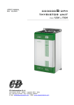
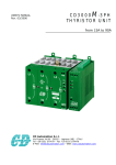
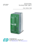
CD3000S-3PH
THYRISTOR UNIT
From
CD Automation S.r.l.
Via Picasso 34/36 - 20025 – Legnano (MI) – Italy
Tel +39 0331 577479 – Fax +39 0331 579479
E-Mail: [email protected] - WEB: www.cdautomation.com
125A to 500A
User’s Manual
CD3000S-3PH from 125A to 500A
C.D. Automation Srl
CD3000S-3PH Thyristor Unit from 125A to 500A
Index:
1.
Glossary
5
1.1 Terminology
1.2 Input signal
1.3 Power feed back
1.4 What is a thyristor unit
2.
Technical specifications
6
2.1 General Features:
2.2 Input features
2.3 Output features
2.4 Derating curve
2.5 Fans
3.
Ordering information
8
4.
Installation and wiring information
9
4.1
5.
Identification of the unit
4.2 Installation
4.3 Dimensions
4.4 Fixing Holes
Wiring instructions
12
5.1
Removing the cover
5.2 Cabling detail
5.3 Wiring connection
5.4 LED Status Table
6.
Start up
19
6.1 Auxiliary supply
6.2 Input configuration
7.
Thyristor firing mode
22
7.1
8.
Zero Crossing(ZC)
Fuses and fuseholder
23
8.1
Fuses and Fuse Code
1
www.cdautomation.com
C.D. Automation Srl
9.
CD3000S-3PH from 125A to 500A
Maintenance
User’s Manual
24
9.1 Trouble Shooting
9.2 Repairing procedure
9.3 Fans
9.4 Servicing
9.5 Warranty conditions
10.
CD Automation's distributors
www.cdautomation.com
26
2
User’s Manual
CD3000S-3PH from 125A to 500A
C.D. Automation Srl
CAUTION
Thyristor units are used in power industrial equipment. When the thyristor unit is working, there are
on the unit the following voltages
- Maximum main supply voltage on power terminals up to 600V.
- Auxiliary supply 230-460Vac.
- Fan voltage 230Vac 50/60Hz Power consumption 14W.
Don't remove the plastic cover which provides adequate protection against electric shock.
Don’t use this thyristor in aerospace and nuclear application.
Electric Shock Hazard (Risque the choque électrique)
When thyristor unit has been connected to main supply voltage and is switched off, before to touch
it be secure that the unit is isolated and wait at least one minute to permit to discharge internal
capacitors. Thus be secure that:
• access to thyristor unit is only permitted to specialized personnel;
• the authorised personnel must read this manual before to have access to the unit;
• the access to the units must be denied to unauthorized personnel.
Important warnings(attention)
• Local regulations regarding electrical installation should be rigidly observed.
• Safety regulations must be rigidly observed.
• Don't bend components to maintain insulation distances.
• Protect the units from high temperature, humidity and vibrations.
• Don't touch components to prevent elettrostatichal discharges on them.
• Verify that all ratings are in line with real needs.
• If authorized personnel must me asure voltage, current etc. on units, take away rings and other
jewels from fingers and hands.
• Authorized personnel working on thyristor unit under power supply voltage must work on insulated
board. Be secure that board is not connected to earth.
This listing does not represent a complete enumeration of all necessary safety cautions.
3
www.cdautomation.com
C.D. Automation Srl
CD3000S-3PH from 125A to 500A
User’s Manual
Protection(protection)
CD3000 thyristor family has a polymeric plastic cover in compliance to International specification
IP20. To understand if IP20 protection is sufficient should be evaluated the installation place where
the units are installed.
Open Type Equipment(équipment de type ouvert).
Maximum surrounding air temperature 40°C(Temperature de l’air environnante maximum 40°C).
Earth(terre)
CD3000 family has isolated heatsink. For safety connect the heatsink to earth to avoid shocks in
case that circuit board or thyristors lost insulation. Earth impedance should be correspondent to
local earth regulation. Periodically the earth efficiency should be inspected.
Electronic Supply(alimentation électronique)
CD3000 family electronic circuit should be supplied by dedicated voltage supply for all electronic
circuit but not in parallel with contactor's coil, solenoids and other inductive or capacitive loads. It's
recommended to use a shielded transformer.
Electromagnetic compatibility (compatibilité électromagnétique)
Our thyristor unit has an excellent immunity to electromagnetic interferences if all suggestions
contained in this manual are respected. In respect to a good Engineering practise, all inductive
loads like solenoids contactor coils should have a filter in parallel.
Emissions (emission)
All thyristor switching at high speed generate some radiofrequency disturbance. CD3000 serie
complies with EMC rules for CE mark. In many installations near electronic devices has not been
noted problems. If radiofrequency device at low frequency are used near the thyristor unit, some
precautions should be taken like line filters and shielded cables for input signal and for load cables.
C
UL
®
US
LISTED
NOTE
We reserves the right to apply modifications to the our products without any advice.
www.cdautomation.com
4
User’s Manual
CD3000S-3PH from 125A to 500A
C.D. Automation Srl
1. Glossary
1.1 Terminology
V:
I:
P:
voltage power supply.
the full circulating current in thyristor unit.
total load power.
1.2 Input signal
SSR:
AN:
IRS:
This input type is a square waveform generated by a temperature controller.
Analog input.
Communication command.
1.3 Power feed back
Feedback: supply voltage fluctuation changes the power to the load. To overcome this effect the
voltage supplied to the load is measured and compared with power demand from controller, the error
signal is used to automatically hold the power at demanded level.
1.4 What is a thyristor unit
A thyristor unit is semiconductor device which acts as a switch formed by two thyristors in
antiparallel. To switch on the alternating current the input signal will be on and the thyristor will
switch off at first zero crossing voltage with no input signal. The benefits of thyristor units
compared with elettromechanical contactors are numerouses: no mooving parts, no maintenance
and capacity to switch very fast. Thyristors are the only solution to control transformers and
special loads that change resistance with temperature and with age.
LOAD
5
www.cdautomation.com
C.D. Automation Srl
CD3000S-3PH from 125A to 500A
User’s Manual
2. Technical specifications
2.1 General Features:
Operating temperature
0÷45°C for higher temperature see derating curve
Voltage power supply
24V minimum, 480V max and 600V on request
Input signal
SSR
Firing mode
Zero Crossing (ZC)
Auxiliary voltage supply
230 à 200÷230V ±15%; 10 VA power consumption
460 à 300÷460V ±15%; 10 VA power consumption
Fan voltage supply
230V ±15%;
110V ±15% on request
Fuses
Internal
Mounting
Bulk head mounting
Protection
IP20
2.2 Input features
Input signal
SSR
www.cdautomation.com
Maximum current
drain
Input
Impedance
5mA constant current
6
ON condition
OFF condition
≥4V-max 30V
≤1V
User’s Manual
CD3000S-3PH from 125A to 500A
C.D. Automation Srl
2.3 Output features
Current
Voltage range
Ripetitive peak
reverse voltage
Leakage
current
I2T value for
fusing
Frequency
range
Power
loss
Isolation
Voltage
(mAeff) (10msec.) (A) (mAeff)
tp=10msec.
(Hz)
I=Inom
(W)
Vac
Latching
current
Max peak
one cycle
(A)
(V)
(480V)
(600V)
125
24÷600
1200
1600
450
2000
15
19100
47÷70
450
2500
150
24÷600
1200
1600
450
2000
15
19100
47÷70
540
2500
225
24÷600
1200
1600
300
4800
15
108000
47÷70
810
2500
300
24÷600
1200
1600
300
5250
15
128000
47÷70
1080
2500
350
24÷600
1200
1600
200
7800
15
300000
47÷70
1260
2500
400
24÷600
1200
1600
200
8000
15
306000
47÷70
1440
2500
450
2 4 ÷6 0 0
1200
1600
1000
17800
15
1027000
47÷70
1620
2500
500
24÷600
1200
1600
1000
17800
15
1027000
47÷70
1800
2500
2.4 Derating curve
K
I
MAX
=I
NOM
xK
1
0.8
0.6
0.4
0.2
0
45
55
65
75
85
°C
2.5 Fans
The thyristor units are equiped with a fan. The fan supply must be protected with a fuse.
Fan voltage supply is standard 230VAC ±15% 50/60Hz or optional 110VAC ± 15% 50/60Hz.
The power consumption is given in the table below.
Size
C
Number of fans
UL
®
LISTED
US
Number of fans
125A, 150A
One Fan - 14W
One Fan - 14W
225A
Two Fans - 30W
Two Fans - 30W
300A, 400A, 500A
Four Fans - 60W
Four Fans - 60W
350A, 450A
Two Fans - 30W
Four Fans - 60W
7
www.cdautomation.com
C.D. Automation Srl
CD3000S-3PH from 125A to 500A
User’s Manual
3. Ordering information
Model CD3000S 3PH
1
2
3
4
5
6
7
CD3000S-3PH
Ex:CD3000S 3PH/
150A/
400V/
480V/
460V/
SSR/
ZC/
UL
1 Nominal CURRENT of CD3000S
125A
300A
450A
150A
350A
500A
225A
400A
2 Operating Load Voltage (incoming voltage supply)
Specify the value of the line supply.
3 Max VOLTAGE of CD3000S
480V
600V
The voltage on the identification label must be equal or more than
operating voltage. The minimum voltage supply to the load is 24V.
4 Auxiliary Voltage
230V
200÷230V ±15%; 10VA
460V
300÷460V ±15%; 10VA
600V
600V ±15%; 10VA (on request)
5 Input
SSR
4÷30VDC
6 Firing
ZC
Zero Crossing
7 Options
FAN110 Fan voltage supply 110VAC ± 15% (std 230VAC ± 15%)
14W 50/60Hz
UL
UL Certification
www.cdautomation.com
8
User’s Manual
CD3000S-3PH from 125A to 500A
C.D. Automation Srl
4. Installation and wiring information
4.1 Identification of the unit
Before to install the CD3000S unit examine for damages or deficiencies. If any is
found, notify the carrier immediately. Check that the product features shown on
CD3000S identification label corresponds to that ordered.
An identification label provide all the informations regarding the factory settings of the unit. This
label is on the board inside the unit, as represented below:
Identification Label
4.2 Installation
CD3000S unit should be always mounted in vertical position to improve air cooling on
heatsink. Maintain minimum distances in vertical and in horizontal as below represented.
Don’t install in proximity of hot elements and near units generating electromagnetic
interferences.
When more units are mounted inside a cubicle provide air circulation as below represented.
Sometimes it is necessary to provide a fan to have better air circulation.
9
www.cdautomation.com
C.D. Automation Srl
CD3000S-3PH from 125A to 500A
User’s Manual
4.3 Dimensions
CD3000S 3PH
125-150A (S11)
CD3000S 3PH
225A (S13)
H
W
CD3000S 3PH
300A-500A (S14)
H
D
H
D
W
W
D
Size
W(mm)
H(mm)
D(mm)
125A (S11)
137
440
270
150A (S11)
137
440
270
225A (S13)
262
440
270
300A (S14)
262
520
270
350A (S14)
262
520
270
400A (S14)
262
520
270
450A (S14)
262
520
270
500A (S14)
262
520
270
www.cdautomation.com
10
User’s Manual
CD3000S-3PH from 125A to 500A
C.D. Automation Srl
4.4 Fixing Holes
A
B
C
Size
A(mm)
B(mm)
C(mm)
125A (S11)
97
415
97
150A (S11)
97
415
97
225A (S13)
222
415
222
300A (S14)
222
495
222
350A (S14)
222
495
222
400A (S14)
222
495
222
450A (S14)
222
495
222
500A (S14)
222
495
222
11
www.cdautomation.com
C.D. Automation Srl
CD3000S-3PH from 125A to 500A
User’s Manual
5. Wiring instructions
5.1 Removing the cover
To open the unit apply as follow.
For S11 size you must open the cover to configure the unit and to view the fuses
For S13 and S14 sizes, you must open the cover to cable, to configure the unit and to view the fuses
Warning: this procedure can be done just by specialized personnel
CD3000S unit has isolated heatsink. For safety connect the heatsink to hearth using its
terminal with hearth symbol.
CD3000S can be susceptible to airborne interferences from near equipment or from interferences on
main supply, so a number of precautions must be taken.
• Contactors coils and chokes must have in parallel a RC filter and must be supplied with a different
voltage line.
• All input/output signal must use screened bifilar wires.
• Signal input and output must not routing in same cable try and must not be parallel.
• Local regulations regarding electrical installation should be rigidly observed.
www.cdautomation.com
12
User’s Manual
CD3000S-3PH from 125A to 500A
C.D. Automation Srl
5.1.1 Auxiliary Terminals
Before connect or disconnect, make sure that the power, control cables and wires are
insulated from the voltage
Terminal
Description
1
Auxiliary supply voltage 230-460Vac (600V opt.)
2
N.C. not connected
3
Auxiliary supply voltage 230-460Vac (600V opt.)
4
N.C. not connected
5
Fan supply 230V (110V opt.)
6
Fan supply 230V (110V opt.)
7
Reset
8
Reset
9
10
+ Input command signal SSR
- Input command signal SSR
11
∅ Volt GND
12
Output + 8Vdc stabilized, 1mA max
13
+Output command signal to CD3000 slave
14
- Output command signal to CD3000 slave
15
Not used
16
Not used
17
Not used
18
Not used
19
Not used
20
Not used
Auxiliary terminals
13
www.cdautomation.com
C.D. Automation Srl
CD3000S-3PH from 125A to 500A
User’s Manual
5.1.2 Power Terminals
Before connect or disconnect, make sure that the power, control cables and wires are
insulated from the voltage
Terminal
L1
T1
L2
T2
L3
T3
Description
Line Input Phase 1
Load Output Phase 1
Line Input Phase 2
Load Output Phase 2
Line Input Phase 3
Load Output Phase 3
S11 power connection
S14 power connection
L1
L2
L3
S13 power connection
L1
L2
T1
L1
L2
T2
T3
T1
www.cdautomation.com
T2
T3
L3
L1 T1 L2
T1
L3
T2
14
T3
T2 L3 T3
User’s Manual
CD3000S-3PH from 125A to 500A
C.D. Automation Srl
5.2 Cabling detail
Use 75°C copper (CU) conductor only, provided with the terminal type indicated below.
Torque/couple
Wire
Current/courant
Wire Range/cable
Lb-in (N-m)
Terminal/terminal
125A, 150A,
225A
310 (35.0)
300A
372 (42.0)
Polymeric Terminal
Block M8
18 - 600kcmil
Bus Bar Adapter M8
350A, 400A
505 (57.0)
Bus Bar Adapter M10
450A, 500A
Bus Bar
15
www.cdautomation.com
C.D. Automation Srl
CD3000S-3PH from 125A to 500A
Power terminals: wire details:
Current
Supply
L1, L2 and L3
Cable
Screw
User’s Manual
Load
T1, T2 and T3
Cable
Screw
mm2
AWG
M
mm2
AWG
M
125A
50
1
M8
50
1
M8
150A
70
1/0
M8
70
1/0
M8
225A
120
4/0
M8
120
4/0
M8
300A
2 x 70 2 x 1/0
M8
2 x 70
2 x 1/0
M8
350A
2 x 95 2 x 3/0
M10
2 x 95
2 x 3/0
M10
400A
2 x 95 2 x 3/0
M10
2 x 95
2 x 3/0
M10
450A
Bus Bar
30 x 6 mm
Bus Bar
30 x 6 mm
500A
Bus Bar
60 x 4 mm
Bus Bar
60 x 4 mm
Auxiliary connectors and earth:
Current
Auxiliary Supply
Earth
Cable
Cable
Screw
mm2
AWG
mm2
AWG
M
125A
0,50
18
16
6
M6
150A
0,50
18
16
6
M6
225A
0,50
18
25
4
M8
300A
0,50
18
50
1
M8
350A
0,50
18
50
1
M8
400A
0,50
18
50
1
M8
450A
0,50
18
70
1/0
M8
500A
0,50
18
70
1/0
M8
www.cdautomation.com
16
User’s Manual
CD3000S-3PH from 125A to 500A
C.D. Automation Srl
5.3 Wiring connection
5.3.1 CD3000S 3PH 125-500A
L1
L2
L3
L1
L2
L3
**
240/460V 1
2
240/460V 3
PE 4
FAN 5
FAN 6
RESET 7
RESET 8
INPUT + 9
INPUT - 10
0V GND
+ 8V
SLAVE +
SLAVE -
T1
T2
T3
FAN SUPPLY 230V Std
INPUT SIGNAL
SSR/Volt/mA
11
12
13
14
15
16
17
18
19
20
Open Delta Load
Delta Load
Star with or without Neutral
Load
Neutral
NOTE: IMPORTANT
* The user installation must be protected by electromagnetic circuit
breaker or by fuse isalator.
** If the auxiliary voltage (written on the identification label) is different
from supply voltage (to the load), use an external transformer, as reported
above.
To work terminals 7-8 must be linked.
Fan voltage supply is standard 230VAC ±15% 50/60Hz or optional 110VAC ±15% 50/60Hz. For power
consumption see fan paragraph.
17
www.cdautomation.com
C.D. Automation Srl
CD3000S-3PH from 125A to 500A
5.4 LED Status Table
LED
STATUS
DESCRIPTION
PW
(green led)
Auxiliary supply is not connect
Auxiliary supply is connect
ON
(green led)
OFF Condition (Load IS NOT Powered)
ON Condition (Load IS Powered)
= Light OFF
www.cdautomation.com
= Light ON
18
User’s Manual
User’s Manual
CD3000S-3PH from 125A to 500A
C.D. Automation Srl
6. Start up
Before to supply the thyristor unit:
• verify that load current equal or less than nominal;
For resistive load (star or delta)
I= P
V3
tot
•
•
•
•
For resistive load open delta
I = Ptot
3V
verify that there is no short circuit on load;
verify that main voltage equal or less than nominal;
verify that all auxiliary connections are right;
fan voltage equal than nominal (230V std , 110V optional)
After which supply thyristor unit giving the maximum input signal and verify that load current is
equal or less than thyristor unit nominal current.
Warning: this procedure can be done just by specialized personnel.
The thyristor unit is delivered configured and tuned in line with customer
requirements. If it’s necessary to change on site the configuration, procede as below
specified.
19
www.cdautomation.com
C.D. Automation Srl
CD3000S-3PH from 125A to 500A
User’s Manual
6.1 Auxiliary supply
Warning: this procedure can be done just by specialized personnel.
To change auxiliary supply voltage sold the correct link-jumper on main PCB.
Auxiliary supply jumpers for S11, S13 and S14 sizes
J11
J10
J9
230V Auxiliary supply
To set the auxiliary power
supply to 230V, close J9 and
J11 and open J10 as shown
below.
J11
460V Auxiliary supply
To set the auxiliary power
supply to 460V, close J10 and
open J9 and J11 as shown
below.
600V Auxiliary supply
This is a special version on request.
In this case the unit is supplied
already configured.
J11
J11
J10
J10
J10
J9
J9
J9
www.cdautomation.com
20
User’s Manual
CD3000S-3PH from 125A to 500A
C.D. Automation Srl
6.2 Input configuration
Warning: this procedure can be done just by specialized personnel.
Location of auxiliary supply jumpers for S11, S13 and S14 sizes
Jumpers Configuration
MAIN PCB
Input
SSR
J7
J16
AB C
J17
CB A
21
J13
CB A
FITTED
www.cdautomation.com
C.D. Automation Srl
CD3000S-3PH from 125A to 500A
User’s Manual
7. Thyristor firing mode
7.1 Zero Crossing(ZC)
ZERO CROSSING
ZC firing mode is used with Logic Output from
temperature controllers and the Thyristor
operate like a contactor. The Cycle time is
performed by temperature controller. ZC
minimize interferences because the Thyristor
unit switch ON-OFF at zero voltage.
VOLTAGE SUPPLY (V)
LOAD VOLTAGE (V)
SSR from controller
www.cdautomation.com
22
User’s Manual
CD3000S-3PH from 125A to 500A
C.D. Automation Srl
8. Fuses and fuseholder
8.1 Fuses and Fuse Code
CD3000S unit must be protected by fuses against short circuit selecting the proper I²t that must be
lower than thyristor one. The same caution must be taken if Circuit Breaker is used. Remember that
is very difficult to protect the thyristor if this choice is done.
WARNING!! Equipment short circuit protected by Semiconductor Fuse type with
proper I2t
Sizes
Bussmann Div - Cooper (UK) Ltd
(200 kA RMS Symmetrical A.I.C.)
Fuse Mod. No.
Current
I2t
2
/modéle fusible
(ARMS)
(A sec)
V ac
125A
2x 100 FE
100
2800
660
150A
2x 100 FE
100
2800
660
300A
450 FMM
450
105000
660
350A
550 FMM
550
215000
660
400A
550 FMM
550
215000
660
450A
700 FMM
700
420000
660
500A
700 FMM
700
420000
660
FERRAZ (200kA @ 660V)
225A
6,6 URB 000
BS88/315
Ferraz Shawmut SA
(200 kA RMS Symmetrical A.I.C.)
Fuse Mod. No.
Current
I2t
2
/modéle fusible
(ARMS)
(A sec)
2 x 6,9 URY
100
3900
17/100
2 x 6,9 URY
100
3900
17/100
6,6 URZ 2X000
450
126000
BS88 Z 450
6,6 URZ 2X000
550
208000
BS88 Z 550
6,6 URZ 2X000
550
208000
BS88 Z 550
6,6 URZ 2x000
700
340000
BS88 Z 700
6,6 URZ 2x000
700
340000
BS88 Z 700
Vac
690
690
660
660
660
660
660
SIBA (300kA @ 600V, 200kA @700V)
315
82000
660
20 559 20
315
77000
660
High speed fuses are only used for the thyristor protection and can not be used to
protect the installation.
The user installation must be protect by electromagnetic circuit breaker or by fuse
isolator.
The warranty of thyristor is null if no proper fuses are used. See tab above.
23
www.cdautomation.com
C.D. Automation Srl
CD3000S-3PH from 125A to 500A
User’s Manual
9. Maintenance
9.1 Trouble Shooting
Small problems sometimes can be solved locally with the help of the below tab of trouble shooting.
If you don’t succeed, contact us or your nearest distributor.
Symptom
LED Indication
Possible reasons of the
symptom
Green LED (PWR)
No voltage auxiliary power
is always light off. supply to terminals 1 -3
(see wiring diagram).
Thyristor unit
Green LED (PWR)
No input signal.
doesn’t go in
light on and green Reversed polarities of
conduction with
LED (ON) in off
input signal.
input signal.
condition.
Reset contact in open
condition (see wiring
diagram).
Load current
Green LED (ON)
Short circuit on thyristor.
flows also with no always in off
Wrong connection.
input signal.
condition.
www.cdautomation.com
24
Actions
Give auxiliary voltage supply to
terminals 1-3.
Provide to give input signal.
Reverse the input signal polarity.
Make link on reset terminals.
Substitute the thyristor. Check that
load is not in short circuit.
User’s Manual
CD3000S-3PH from 125A to 500A
C.D. Automation Srl
9.2 Repairing procedure
•
•
•
•
•
Phone to us.
Explain to Service Engineer the problem because sometimes it can be solved with a phone call.
If this is not possible ship the unit to us or to your distributor.
Write a fault description and give the name of your personnel to which refer.
Use a rugged packaging to ship the unit.
9.3 Fans
The thyristor unit with forced ventilation uses fans that rotate permanently when the unit is
supplied. In case of accidental fan failure, there is an over heating temperature on heatsink. In this
case to give protection to thyristor there is a thermal switch properly setted. The function of this
switch is to open the input signal until the heatsink temperature falls below the setted value. This
means that also with input signal in ON condition the unit is switched OFF and the system can not
work at full power. For these reason is important to control periodically the fan status checking that
is rotating.
9.4 Servicing
In order to have correct cooling, the user must clean the heatsink and the protective grill of fan.
The frequence of this servicing depends on environmental pollution.
Check periodically also if the screw for the power cables and safety earth are tightened correctly
9.5 Warranty conditions
We gives a 12 months warranty to its products. The warranty is limited to repairing and parts
substitution in our factory and does exclude products not properly used and fuses.
Warranty does not includes products with serial numbers deleted. The faulty product should be
shipped to us at your cost and our Service will evaluate if product is under warranty terms.
Substituted parts remains our property.
25
www.cdautomation.com
C.D. Automation Srl
CD3000S-3PH from 125A to 500A
10. CD Automation's distributors
For a more precise and rapid service, please contact the distributor nearest to you:
ITALY
CABE S.r.l.
Via Ferrara, 15/17
40018 S. Pietro in Casale (BO)
Tel: 051 6661345
Fax: 051 6661283
Sig. Bergonzoni
[email protected]
Vectra Misure S.r.l.
Via Gaidano, 109/17
10137 Torino (TO)
Tel: 011 3097003
Fax: 011 3098799
Sig. Cochis
[email protected]
CEAM Control Equip. S.r.l.
Via Val d'Orme, 291
50053 Empoli (FI)
Tel: 0571 924181
Fax: 0571 924505
Sig. Campinoti
[email protected]
Secif S.a.s.
Via Bachelet, 27
35010 Busa di Vigonza (PD)
Tel: 049 8934422
Fax: 049 8934415
Sig. Ferro
[email protected]
Studio Rapaccini S.a.s.
Via del Rivo, 138
05100 Terni (TR)
Tel: 0744 305105
Cell: 335 6163428
Fax: 0744 305110
Dott. Rapaccini
[email protected]
INTERNATIONAL DISTRIBUTORS
PICS NV
Middelmolenlaan, 110
2100 Deurne
Belgium
Tel: +32 332 65959
Fax: +32 332 66770
Mr. Berge Billiauws
http://www.pics.be
OY E Sarlin AB
PL-750
00101 Helsinki
Finland
Tel: +358 950444259
Fax: +358 95666951
Mr. Tapio Ala Ketola
http://www.sarlin.com
Hengstler Div. Cont. Ind.
94-106 Rue B. Pascal Z.I. des Mardelles
93602 Aulnay Sous Bois Cedex
France
Tel: +33 148795541
Fax: +33 1498795561
Mr. Laurent Mulley
Mesa Industrie-Elektronik GmbH
Elbestr., 10
45768 Marl
Germany
Tel: +49 2365915220
Fax: +49 2365915225
Mr. Peter Hallwas
Hengstler GmbH
Uhlandst, 49
D-78554 Aldingen
Germany
Tel: +49 7424890
Fax: +49 742489500
Mr. Armin Belle
Toshniwal Instruments Mfg Pvt Ltd
PO Gagwana Pin
305023 Dist. Ajmer
India
Tel: +91 145420506
Fax: +91 145420505
Mr. Ravi Toshniwal
www.cdautomation.com
26
User’s Manual
User’s Manual
CD3000S-3PH from 125A to 500A
C.D. Automation Srl
CasCade Automation Systems BV
Ridderhaven, 16
2984 BT Ridderkerk
The Netherlands
Tel: +31 180463870
Fax: +31 180485921
Mr. Patrick Braams
http://www.cascade-a-s.com
[email protected]
Paragon Alliance
30, Summerhill Drive - Felpham
PO22 6AS Bognor Regis - West Sussex
England
Tel: +44 1243587170
Fax: +44 1243587270
Mr. Jeremy Watson
http://www.paragonalliance.co.uk
[email protected]
Teck Instrument AS
Verksveien, 7
N-3330 Skotselv
Norway
Tel: +47 32 241300
Fax: +47 32 241301
Mr. Johan Petter Haffner
http://www.teck.no
[email protected]
LA-Konsult AB
Agatan, 1
73440 Hallstahammar
Sweden
Tel: +46 22010905
Fax: +46 22010403
Mr. Leif Johansson
http://www.la -konsult.se
[email protected]
SRC Sistemas de Regulacion y Control, SL
Avda. del Cantabrico, 11. Pabellon, 6
Poligono Industrial Betoño
01013 Vitoria-Gasteiz (Alava)
Spain
Tel: +34 945259455
Fax: +34 945258852
[email protected]
http://www.srcsl.com
CONTROLTEMP, SL
C/ Rafael Casanovas, 21 local.
08130 Sta Perpetua de Mogoda
Barcelona
Spain
Tel: +34 935741320
Fax: +34 935744116
[email protected]
http://www.controltemp.net
CRA - Mess-, Regel- + Antriebstechnik AG
Stampfstrasse, 74
CH-8645 Jona
Switzerland
Tel: +41 552126959
Fax: +41 552126960
Mr. Chiauzzi
http://www.cra.ch
[email protected]
Danaher Corporation
1675 Delany Road
Gurnee, IL 60031-1282
USA
Tel: +1 8473605310
Fax: +1 8476626633
Mr. Andrew Ross
http://www.dancon.com
[email protected]
Electronica Francisco Palma Saavedra
Av. Amerigo Vespucio 513-B
Villa Alto Jahuel, 2 - Pudahuel - Santiago
Chili
Tel: +56 27482023
Fax: +56 27482032
Mr. Francisco Palma S.
[email protected]
Beta Technic Aps
Bygstubben, 5
DK - 2950 Vedbaek
Denmark
Tel: +45 45662208
Fax: +45 45662206
Sune Granzow
http://www.betatechnic.dk
Bresimar LDA
Quinta Do Simao en 109 Esgueira
997 Aveiro
Portugal
Tel: +351 214951760
Fax: +351 234303329
Mr. Carlos Breda
C D 3 0 0 0 S 3 P H 1 2 5 - 5 0 0 A I N G - 03.doc
27
www.cdautomation.com