1
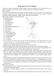
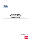
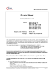
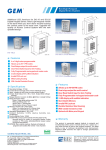
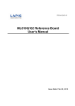
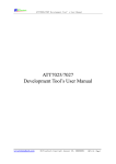
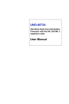
15LD-1079-03E LAPIS Semiconductor Errata ML620Q500 Series Issue date: Oct. 16th 2015 15LD-1079-03E Notes 1) The information contained herein is subject to change without notice. 2) Although LAPIS Semiconductor is continuously working to improve product reliability and quality, semiconductors can break down and malfunction due to various factors. Therefore, in order to prevent personal injury or fire arising from failure, please take safety measures such as complying with the derating characteristics, implementing redundant and fire prevention designs, and utilizing backups and fail-safe procedures. LAPIS Semiconductor shall have no responsibility for any damages arising out of the use of our Products beyond the rating specified by LAPIS Semiconductor. 3) Examples of application circuits, circuit constants and any other information contained herein are provided only to illustrate the standard usage and operations of the Products. The peripheral conditions must be taken into account when designing circuits for mass production. 4) The technical information specified herein is intended only to show the typical functions of the Products and examples of application circuits for the Products. No license, expressly or implied, is granted hereby under any intellectual property rights or other rights of LAPIS Semiconductor or any third party with respect to the information contained in this document; therefore LAPIS Semiconductor shall have no responsibility whatsoever for any dispute, concerning such rights owned by third parties, arising out of the use of such technical information. 5) The Products are intended for use in general electronic equipment (i.e. AV/OA devices, communication, consumer systems, gaming/entertainment sets) as well as the applications indicated in this document. 6) The Products specified in this document are not designed to be radiation tolerant. 7) For use of our Products in applications requiring a high degree of reliability (as exemplified below), please contact and consult with a LAPIS Semiconductor representative: transportation equipment (i.e. cars, ships, trains), primary communication equipment, traffic lights, fire/crime prevention, safety equipment, medical systems, servers, solar cells, and power transmission systems. 8) Do not use our Products in applications requiring extremely high reliability, such as aerospace equipment, nuclear power control systems, and submarine repeaters. 9) LAPIS Semiconductor shall have no responsibility for any damages or injury arising from non-compliance with the recommended usage conditions and specifications contained herein. 10) LAPIS Semiconductor has used reasonable care to ensure the accuracy of the information contained in this document. However, LAPIS Semiconductor does not warrant that such information is error-free and LAPIS Semiconductor shall have no responsibility for any damages arising from any inaccuracy or misprint of such information. 11) Please use the Products in accordance with any applicable environmental laws and regulations, such as the RoHS Directive. For more details, including RoHS compatibility, please contact a ROHM sales office. LAPIS Semiconductor shall have no responsibility for any damages or losses resulting non-compliance with any applicable laws or regulations. 12) When providing our Products and technologies contained in this document to other countries, you must abide by the procedures and provisions stipulated in all applicable export laws and regulations, including without limitation the US Export Administration Regulations and the Foreign Exchange and Foreign Trade Act. 13) This document, in part or in whole, may not be reprinted or reproduced without prior consent of LAPIS Semiconductor. Copyright 2015 LAPIS Semiconductor Co., Ltd. 2-4-8 Shinyokohama, Kouhoku-ku, Yokohama 222-8575, Japan 1/6 15LD-1079-03E 1. Introduction A part of functions on ML620Q500 Series (ML620Q503/504) has a bug. And User’s manual has defective descriptions.This document describes the details and the workaround. Target User’s manual : FEUL620Q504-01 1.1 Issue List No. 1 2 3 4 5 6 Issue Date 2015.04.21 2015.06.09 2015.06.09 2015.10.16 2015.10.16 2015.10.16 Update 2015.10.16 - Subject Interrupt Controller: Interrupt Request Level Control function UART with FIFO: Note in case of stopping clock Port3 :Setting of Port 3 Controll Register High-speed External Clock: Frequency range Power-down/on Procedures Memory mapping of ML620Q503 2. Detail Description 2.1 Interrupt Controller: Interrupt Request Level Control function A part of interrupt controller has a bug. This document describes the bug details and the workaround. For more details about the function of interrupt controller, see the ML620Q503/504 User’s Manual. 2.1.1 Bug (1) There are conditions that Current Interrupt Request Level Register (CILL) can not be cleared and the CPU does not accept pending interrupts which level is same as (or lower than) the level remained in the CILL. Conditions : When using the “Interrupt Level Control Function” (When the Interrupt Level Control Enable Register ILENL is set to "1"). When the CPU executes ROM referece instructions & different level interrupts are generated at the same time in oder of “lower level higher level”, or when the CPU executes instructions that clear the CILL at the same time as that WDTINT(Watch dog timer interrupt) is accepted. 2.1.2 Bug (2) There are condtions that the interrupt level the CPU handles does not equal to the interrupt level the CILL holds. Also, higher level interrupt process have a wait when enabling multiple interrupts or competing with NMI(Non Maskable Interrupt). Conditions : When using the “Interrupt Level Control Function” (When the Interrupt Level Control Enable Register ILENL is set to "1"). When the CPU executes ROM referece instructions & different level interrupts are generated at the same time in oder of “lower level higher level”. 2.1.3. Workaround No workaround. Can not propose complete workaround for the all user’s application software. Do not use the “Interrupt level control function”. ML620Q503H/504H have fixed this bug. There have been released on Oct. 2015. 2/6 15LD-1079-03E 2.2 UART with FIFO: Note in case of stopping clock A note in 14.3.1 and 14.3.4 of ML620Q503/Q504 User’s manual is modified. (Current description) [Note] Transmit FIFO is an empty state, but there is the case that all transmit processing doesn’t complete.Confirm that transmit shift register (TSR) became empty in UF0TEMT bit of UAF0LSR register before stopping high-speed clock (Transition to modes such as STOP / DEEP-HALT / HALT-H). (Modified desctiption) [Note] Even if the Transmit FIFO is empty, some transition processing might not be completed. Before stop the high-speed clock (shift to STOP, DEEP-HALT, HALT-H), confirm the transmit shift register (TSR) becomes empty by UF0TEMT of UAF0LSR register first. And then wait for 1.5bit transmission time regardless of the setting of Parity and Stop bit. 2.3 Port3 : Setting of Port 3 Control Register Actions of P34 to P37 are different from bit descriptions of Port 3 control register in 20.2.4 of ML620Q503/ Q504 User’s manual. These are dependent on setting to Port 3 mode register. The bit descriptions is modified. (Current description) When output mode is selected (P3nDIR bit = “0”) Setting of P3n pin When input mode is selected (P3nDIR bit = “1”) P3nC1 P3nC0 0 0 High-impedance output (initial value) Description High-impedance input 0 1 P-channel open drain output Input with a pull-down resistor 1 0 N-channel open drain output Input with a pull-up resistor 1 1 CMOS output High-impedance input n = 4 to 7. (Modified desctiption) Setting of P3n pin When output mode is selected (P3nDIR bit = “0”) When 2nd/3rd/4th function is selected (P3nMD1,P3nMD0≠“00”) When 1st function is selected (P3nMD1,P3nMD0=“00”) When input mode is selected (P3nDIR bit = “1”) P3nC1 P3nC0 Description 0 0 High-impedance output (initial value) N-channel open drain output High-impedance input 0 1 P-channel open drain output CMOS output Input with a pull-down resistor 1 0 N-channel open drain output N-channel open drain output Input with a pull-up resistor 1 1 CMOS output CMOS output High-impedance input n = 4 to 7. 3/6 15LD-1079-03E 2.4 High-speed External Clock : Frequency range A frequncy range of high-speed external clock input is modified (in section 1.Overview and Appendix C of the User’s manual). (Previous range ) : 300kHz to 16MHz (Modified range) : 2MHz to 16MHz 2.5 Power-down/on Procedures A Power-on procedures and constraints are modified (in Appendix C of the User’s manual). (Previous procedures and consraints ) 10ms or less 0.9×VDD VDD 0.1×VDD 30mV or less (VSS = 0) over 2sec (Modified procedures and consraints) 0.9*VDD VDD 0.1*VDD 30mV or less (VSS = 0) TPOR VDDL 100mV or less Note: If VDDL level is 100mV or more over, reset the IC by RESET_N pin after power-on. 4/6 (VSS = 0) 15LD-1079-03E 2.6 Memory mapping of ML620Q503 Memory mapping of ML620Q503 is modified (in section 2.CPU and Memory Space of the User’s manual). (Previous mapping ) : CSR:PC 0:0000H 0:00FFH 0:0100H Code segment 0 Vector table or Program code Program code 0:7BFFH 0:7C00H 0:7DFFH 0:7E00H 0:7FFFH Test data area (Rewritable) Test data area (Not rewritable) 8bit (Modified mapping) : CSR:PC 0:0000H 0:00FFH 0:0100H Code segment 0 Vector table or Program code Program code 0:7BFFH 0:7C00H Unused area 0:0FBFFH 0:0FC00H 0:0FDFFH 0:0FE00H 0:0FFFFH Test data area (Rewritable) Test data area (Not rewritable) 8bit 5/6 15LD-1079-03E Revision History Document No. Issue date 15LD-0165-01E 15LD-0165-02E 2015.04.21 2015.06.09 15LD-1079-03E 2015.10.16 Page Before After revised revised – – – 3 2 2 – 4,5 6/6 Description First revision Add Issue No.2,3 Updated description in section 2.1.3. Add Issue No. 4,5,6