1
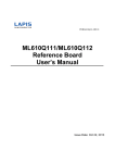
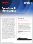
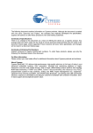
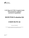
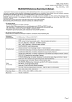
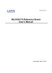
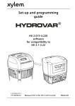
FEBL620Q504H_RB-01
ML620Q504H
Reference Board
User’s Manual
Issue Date: AUG 31, 2015
ML620Q504H Reference Board User’s Manual
Notes
1) The information contained herein is subject to change without notice.
2) Although LAPIS Semiconductor is continuously working to improve product reliability and quality, semiconductors can
break down and malfunction due to various factors. Therefore, in order to prevent personal injury or fire arising from failure,
please take safety measures such as complying with the derating characteristics, implementing redundant and fire
prevention designs, and utilizing backups and fail-safe procedures. LAPIS Semiconductor shall have no responsibility for
any damages arising out of the use of our Products beyond the rating specified by LAPIS Semiconductor.
3) Examples of application circuits, circuit constants and any other information contained herein are provided only to illustrate
the standard usage and operations of the Products. The peripheral conditions must be taken into account when designing
circuits for mass production.
4) The technical information specified herein is intended only to show the typical functions of the Products and examples of
application circuits for the Products. No license, expressly or implied, is granted hereby under any intellectual property
rights or other rights of LAPIS Semiconductor or any third party with respect to the information contained in this
document; therefore LAPIS Semiconductor shall have no responsibility whatsoever for any dispute, concerning such rights
owned by third parties, arising out of the use of such technical information.
5) The Products are intended for use in general electronic equipment (i.e. AV/OA devices, communication, consumer systems,
gaming/entertainment sets) as well as the applications indicated in this document.
6) The Products specified in this document are not designed to be radiation tolerant.
7) For use of our Products in applications requiring a high degree of reliability (as exemplified below), please contact and
consult with a LAPIS Semiconductor representative: transportation equipment (i.e. cars, ships, trains), primary
communication equipment, traffic lights, fire/crime prevention, safety equipment, medical systems, servers, solar cells, and
power transmission systems.
8) Do not use our Products in applications requiring extremely high reliability, such as aerospace equipment, nuclear power
control systems, and submarine repeaters.
9) LAPIS Semiconductor shall have no responsibility for any damages or injury arising from non-compliance with the
recommended usage conditions and specifications contained herein.
10) LAPIS Semiconductor has used reasonable care to ensure the accuracy of the information contained in this document.
However, LAPIS Semiconductor does not warrant that such information is error-free and LAPIS Semiconductor shall have
no responsibility for any damages arising from any inaccuracy or misprint of such information.
11) Please use the Products in accordance with any applicable environmental laws and regulations, such as the RoHS Directive.
For more details, including RoHS compatibility, please contact a ROHM sales office. LAPIS Semiconductor shall have no
responsibility for any damages or losses resulting non-compliance with any applicable laws or regulations.
12) When providing our Products and technologies contained in this document to other countries, you must abide by the
procedures and provisions stipulated in all applicable export laws and regulations, including without limitation the US
Export Administration Regulations and the Foreign Exchange and Foreign Trade Act.
13) This document, in part or in whole, may not be reprinted or reproduced without prior consent of LAPIS Semiconductor.
Copyright
2015 LAPIS Semiconductor Co., Ltd.
2-4-8 Shinyokohama, Kouhoku-ku,
Yokohama 222-8575, Japan
http://www.lapis-semi.com/en/
FEBL620Q504H_RB-01
1
ML620Q504H Reference Board User’s Manual
Preface
This manual describes the operation of the ML620Q504H Reference Board, which the ML620Q504H,
LAPIS SEMICONDUCTOR’s ultra low-power 16-bit microcontroller is mounted.
ML620Q504H is carried as MCU in ML620Q504H Reference Board.
This board can be used as ML620Q503H.
When using ML620Q503H, select ML620503F to target MCU.
When using ML620Q504H, select ML620504F to target MCU.
The following manuals are also available. Please read them as necessary.
-
ML620Q503H/Q504H User’s Manual
Description on the ML620Q503H/Q504H hardware
-
uEASE User’s Manual
Description on the on-chip debug tool uEASE
FEBL620Q504H_RB-01
2
ML620Q504H Reference Board User’s Manual
1.
Hardware overview
The ML620Q504H Reference Board is prepared for having you study the operations of the ML620Q503H/
Q504H by connecting the on-chip debug emulator uEASE ( hereafter “uEASE”) , the ML620Q504H
Reference Board enables software development, debug and Flash programming into the device with using
the software development tool bundled with the uEASE.
This board also works in stand-alone mode without uEASE bus supplying power externally.
Before starting work with this board, please read below carefully and understand notices.
1.1 Features
- On-chip debugging and Flash programming are supported by using the TEST0 pin and TEST1_N pin,
- Power supply can be provided from the uEASE or the customer’s target board.
1.2 Hardware Specifications
The hardware specifications of this reference board are shown in the following table.
Embedded
microcontroller
ML620Q504H Reference Board
U1: ML620Q504H
JP1: Jumper for selecting power supply ( 3pin pin-header and
short pin )
JP2: Jumper for selecting reference voltage for SA-ADC (VREF)
( 3pin pin-header and short pin )
CNuE: Connector for on-chip debug emulator ( 14pins )
Embedded
components
SW1: Switch for reset input ( tact switch )
SW2: Switch for P51 input ( tack switch )
SW3: Switch for hardware re-mapping *
LED1-2: LED ( LED1 and LED2 are connected with P52 and
P53 respectively )
XT1: 32.768kHz crystal
XT3: 16MHz ceramic
Operating Voltage
+1.8V ~ +5.5V
Size
71.12 mm x 53.34 mm
FEBL620Q504H_RB-01
oscillator
3
ML620Q504H Reference Board User’s Manual
1.3 View of the ML620Q504H reference board
Figure 1 The ML620Q504H reference board size and external components
FEBL620Q504H_RB-01
4
ML620Q504H Reference Board User’s Manual
2. Function
SW2(USW)
SW3(TEST0)
LED1-2
PP5-15
for
SA-ADC/RC-ADC
JP1(VDDSEL)
JP2(VREFSEL)
SW1(RST)
PP1-4
for SA-ADC
2.1 Jumper for Power Supply
Connect between ① and ②
① ②
③
Connect between ②and ③
① ②
③
JP1(VDDSEL)
Supply power from TP1(UVDD)
Supply power from the uEASE. The
current supply capability of the
uEASE is 100mA @3.3V.
JP2(VREFSEL)
VREF is provided from TP1(UVDD) .
VREF is provided from TP2(VREF).
[Note]
When supplying LSI with power supply from outside, please connect TP1 to UVDD.( Connect
between ① and ②)
2.2 SW1(RST)
SW1 is a tack switch connected to the RESET_N pin.
By pressing this SW1, the ML620Q504H causes reset.
FEBL620Q504H_RB-01
5
ML620Q504H Reference Board User’s Manual
2.3 SW2(USW)
SW2 is a tack switch connected to the P51 pin.
When use the P51 pin, please connect the pull-up resister by setting SFR of the ML620Q504H.
When remove this SW2, please cut the PCB pattern at J1 as shown in the below picture.
Cut the PCB pattern at J1
2.4 SW3(TEST0)
SW3 is used for selecting hardware re-mapping.
When use hardware re-mapping, please set this SW3 to “ISP”.
When do not use hardware re-mapping, please set this SW3 to “USR”.
2.5 LED1-2
LED1 and LED2 are connected with P52 and P53 respectively.
When use LED, please set the P52 and P53 into N-ch open-drain output by setting SFR of the
ML620Q504H. By output “0” at P52 and P53, LED1 and LED2 turns on respectively.
When do not use LED1 and LED2, please cut the PCB pattern at J2 and J3 as shown in the below picture.
Cut the PCB pattern at J2 and J3
FEBL620Q504H_RB-01
6
ML620Q504H Reference Board User’s Manual
2.6 SA-ADC
When use the SA-ADC, please connect the input to be measured at the P34-37(AIN0-3), P20-23(AIN4-7) or
P00-03(AIN8-11). When use the noise reduction capacitor for AIN0-11, please connect at PP1-4, PP5-8 or
PP10-13. And please note that the PCB pattern at PP9 needs to be connected, when the noise reduction
capacitors are necessary at PP5-8, and also the PCB pattern at PP15 needs to be connected, when the
noise reduction capacitors are necessary at PP10-13.
The PCB pattern at PP15 needs to be
connected, when the noise reduction
capacitors are necessary at PP10-13
The PCB pattern at PP9 needs to be
connected, when the noise reduction
capacitors are necessary at PP5-8
2.7 RC-ADC
When use the channel-0 of RC-ADC, please connect capacitors and resisters at PP10-15.
When use the channel-1 of RC-ADC, please connect capacitors and resisters at PP5-9.
RC oscillation can be monitored at TP5(RCM).
PP10-15 are used for the channel-0 of RC-ADC
PP5-9 are used for the channel-1 of RC-ADC
FEBL620Q504H_RB-01
7
ML620Q504H Reference Board User’s Manual
3. Important notice
(1) Please read and understand the ML620Q503H/Q504H user’s manual and uEASE user’s manual, before
using the ML620Q504H reference board.
(2) The reference board may sometime use the engineering sample of the ML620Q504H. Therefore please
use the mass production part of the ML620Q504H for final evaluation of the customer’s system.
(3) When set the JP1 jumper to use UVDD and connect the uEASE to the ML620Q504H reference board,
please power on the customer’s target board fist before activate the uEASE. And also power-off the
uEASE first before power off the customer’s target board.
(4) When set the JP1 jumper to use UVDD, the current supply capability of the uEASE is 100mA @3.3V.
(5) The ML620Q504H has PCB layout in back surface. Therefore when put this board on a conductive
material, it may cause malfunction due to causing a short circuit. Please use an insulation sheet or attach
legs to prevent a short circuit.
(6) LAPIS Semiconductor will not provide any support for this board, but the board can be exchanged with
a new product only when it has an initial failure.
FEBL620Q504H_RB-01
8
ML620Q504H Reference Board User’s Manual
4. Circuit diagram
(1/2)
FEBL620Q504H_RB-01
9
ML620Q504H Reference Board User’s Manual
(2/2)
FEBL620Q504H_RB-01
10
ML620Q504H Reference Board User’s Manual
5. Parts list
Parts Number
Silk
Contents
Package Type
Qty.
Maker
1
GRM188B31C105K
C1-3
Ceramic Capacitor
1.0μF/16V B
1608
3
MURATA
2
GRM188B31C225K
C4
Ceramic Capacitor
2.2μF/16V B
1608
1
MURATA
3
GRM1882C1H120J
C5-6
Ceramic Capacitor
12pF/50V CH
C7-8
Do Not Place
3.3μF/10V B
1608
2
MURATA
1608
2
MURATA
1608
1
MURATA
4
GRM188B11A334K
C9
Ceramic Capacitor
5
GRM188B316xxxK
C10-11
Do Not Place
1608
2
-
6
A2-12PA-2.54DSA(71)
CN1-4
Do Not Place
12PIN
4
HIROSE
7
PSM-420336-07
CNuE
14pin Header
14PIN
1
HIROSUGI
8
J1608
J1-3
Do Not Place
2012
3
-
9
PSM-410336-03
JP1-2
3pin Header
3PIN
2
HIROSUGI
11
XJ8C-0211
JP3
Do Not Place
2PIN_S
1
OMRON
12
SML-219DT
LED1-2
LED Orange
2012
2
ROHM
13
TH
PP1-15
Do Not Place
2PIN
15
-
14
MCR03EZPJ681
R1-2
Resistor 680Ω
1608
2
ROHM
15
MCR03EZPJ000
R3-4
Resistor 0Ω
1608
2
ROHM
R5-6
Do Not Place
1608
2
ROHM
SKHUALE010
SW1-2
Tact Switch
4PIN
2
ALPS
17
CAS-120B1
SW3
Jumper Switch
3PIN
1
COPAL
18
LC-2-G(R)
TP1-2
Do Not Place
TH
2
MAC EIGHT
19
LC-2-G(B)
TP3-4
Do Not Place
TH
2
MAC EIGHT
20
LC-2-G(Y)
TP5
Do Not Place
TH
1
MAC EIGHT
21
ML620Q504H-nnnTB
U1
MCU
48PQFP
1
LAPIS
22
DT-26 CL=6pF
XT1
Crystal Unit 32.768KHz
2PIN
1
DAISHINKU
23
NX8045GB-16.000M-STD-CSF-6
XT2
Do Not Place
2PIN
1
NDK
24
CSTCE16M0V53
XT3
Ceramic Resonator 16.000MHz
3PIN
1
MURATA
25
QTU-11712-2
-
PCB
-
1
LAPIS
26
JS-41060
-
Short Socket
-
3
HIROSUGI
27
B-P40
-
Anti-Vibration Feet
-
4
TAKACHI
16
FEBL620Q504H_RB-01
11
ML620Q504H Reference Board User’s Manual
6. Revision History
Page
Document No.
FEBL620Q504H_RB-01
FEBL620Q504H_RB-01
Date
AUG.31,2015
Previous
Current
Edition
Edition
-
-
Description
Formally Edition 1.0
12