1
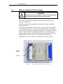
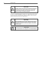
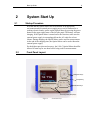
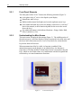
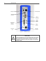
Model 1918-C
Hand-held Optical Meter
Start Up Guide
Start Up Guide
First printing 2006
© 2006 by Newport Corporation, Irvine, CA. All rights reserved. No part of
this start up guide may be reproduced or copied without the prior written
approval of Newport Corporation.
This start up guide has been provided for information only and product
specifications are subject to change without notice. Any change will be
reflected in future printings.
Newport Corporation
1791 Deere Avenue
Irvine, CA, 92606
USA
Part No. 90000777, Rev. A
1
User’s Manual and Future Updates
Dear Customer,
This Start Up Guide contains essential information, including
safety precautions and start up procedures, needed to get your new
optical meter up and running. Please review it prior to unpacking
and powering up the instrument.
Other important information regarding the use and operation of
the optical meter is included in the complete User’s Manual.
The complete User’s Manual in Adobe PDF format, and the
instrument software drivers, are included on the accompanying
CD. You can also view a copy of the User’s Manual, and obtain
the instrument software drivers, on the Newport web site.
In an effort to keep the 1918-C Optical Meter optimized for your
applications, Newport will on occasion update existing and add
new features to this instrument. To utilize this new functionality
will require an update to the instrument's firmware, which can
be easily accomplished by the user, as described in the User’s
Manual.
Please check the product page on the Newport web
site (www.Newport.com) for newer versions of the firmware
and the User’s Manual. Call your local Newport application
specialist if you need support with locating or downloading
these files.
Enjoy your new instrument!
Start Up Guide
3
EU Declaration of
Conformity
We declare that the accompanying product, identified with the
mark,
complies with requirements of the Electromagnetic Compatibility Directive,
89/336/EEC and the Low Voltage Directive 73/23/EEC.
Model Number: 1918-C
Year
mark affixed: 2006
Type of Equipment: Electrical equipment for measurement, control and
laboratory use.
Standards Applied:
Compliance was demonstrated to the following standards to the extent
applicable:
BS EN61326-1: 1997+A1+A2 +A3 “Electrical equipment for measurement,
control and laboratory use – EMC requirements”
Performance criteria B was achieved during immunity tests.
This equipment meets the CISPR 11 Class A Group 1 radiated and conducted
emission limits.
BS EN 61000-3-2:2001, Harmonic current emissions, Class A
BS EN 61000-3-3:2002, Voltage fluctuations and flicker
BS EN 61010-1:2001, 2nd Edition “Safety requirements for electrical
equipment for measurement, control and laboratory use”
Bruno Rety
Group Director of PPT Instrument and Motion Europe
Zone Industrielle
45340 Beaune-la-Rolande, France
Dan Dunahay
Director of Quality Systems
1791 Deere Avenue
Irvine, Ca. USA
4
Start Up Guide
1
Safety Precautions
Please carefully read the following important safety precautions prior to
unpacking and operating this equipment. In addition, please refer to the
complete User’s Manual for additional important notes and cautionary
statements regarding the use and operation of the equipment.
1.1
Symbols and Definitions
The following are definitions of symbols that are used throughout this Start
Up Guide to call your attention to important information regarding your
safety, the safety and preservation of your equipment or an important tip.
WARNING
Situation has the potential to cause bodily harm or death.
CAUTION
Situation has the potential to cause damage to property or
equipment.
ELECTRICAL SHOCK
Hazard arising from dangerous voltage. Any mishandling could
result in irreparable damage to the equipment, and personal
injury or death.
NOTE
Additional important information the user or operator should consider.
1.2
General Warnings
Observe these general warnings when operating or servicing this equipment:
•
•
•
•
•
•
Heed all warnings on the unit and in the operating instructions.
Do not use this equipment in or near water.
Route power cords and other cables so they are not likely to be damaged.
Disconnect power before cleaning the equipment. Do not use liquid or
aerosol cleaners; use only a damp lint-free cloth.
Lockout all electrical power sources before servicing the equipment.
To avoid explosion, do not operate this equipment in an explosive
atmosphere.
Start Up Guide
•
1.3
5
Qualified service personnel should perform safety checks after any
service.
General Cautions
Observe these cautions when operating or servicing this equipment:
•
•
•
•
•
•
•
•
•
1.4
If this equipment is used in a manner not specified in this manual, the
protection provided by this equipment may be impaired.
Do not position this product in such a manner that would make it
difficult to disconnect the power cord.
There are no user-serviceable parts inside the 1918-C Optical Meter,
with the exception of the battery.
Use only the Newport Model 1918-BAT battery.
Use only the Newport Model 1918-PS external power supply.
Follow precautions for static sensitive devices when handling this
equipment.
This product should only be powered as described in the manual.
To prevent damage to the equipment, read the instructions in the
equipment manual for proper input voltage.
Adhere to good laser safety practices when using this equipment.
Unpacking and Handling
It is recommended that the 1918-C Optical Meter be unpacked in a lab
environment or work site. Inspect the box carefully to verify all items
identified in section 1.6 are included.
1.5
Inspection for Damage
The 1918-C Optical Meter is carefully packaged at the factory to minimize
the possibility of damage during shipping. Inspect the box for external signs
of damage or mishandling. Inspect the contents for damage. If there is
visible damage to the instrument or accessories upon receipt, inform the
shipping company and Newport Corporation immediately.
WARNING
Do not attempt to operate this equipment if there is evidence of
shipping damage or you suspect the unit is damaged. Damaged
equipment may present additional hazards to you. Contact
Newport technical support for advice before attempting to plug
in and operate damaged equipment.
6
Start Up Guide
1.6
Parts List
The following is a list of parts included in the hardcase with the 1918-C
Optical Meter:
1. This Quick Start Guide (Hard copy)
2. CD containing the Software Drivers and Utilities and the User Manual
3. Battery 1918-BAT
4. External Power Supply 1918-PS
5. Power cord 1918-PSC
If you are missing any hardware or have questions about the hardware you
have received, please contact Newport Corporation.
1.7
Choosing and Preparing a Suitable Work Surface
The Model 1918-C Optical Meter may be placed on any reasonably firm
table or bench during operation. The kickstand can be rotated to two angles
to improve visibility of the LCD display, as needed.
Provide adequate distance between the Model 1918-C Optical Meter and
adjacent walls for ventilation purposes. Approximately 2-inch spacing for all
surfaces is adequate.
1.8
Electrical Requirements
Before attempting to power up the unit for the first time, the following
precautions must be followed:
• If the power supply is equipped with a 3-prong plug, connect the
instrument to properly earth-grounded 3-prong receptacle only.
WARNING
If the power supply is equipped with a 3-prong plug, connect the
instrument to properly earth-grounded, 3-prong receptacles
only. Failure to observe this precaution can result in severe
injury.
• Have a qualified electrician verify the wall socket that will be used is
properly polarized and properly grounded.
Start Up Guide
1.9
7
Battery and External Power Supply
CAUTION
The battery needs to be charged for at least 4 hours before using
the optical meter without the external power supply.
The 1918-C Optical Meter is shipped from the factory with the battery
removed from the unit.
Install the battery before plugging the external power supply and before
turning on the unit.
To install the battery, first remove the battery compartment cover from the
back of the unit. Connect the 5-pin battery connector to the corresponding
connector inside the battery compartment (Figure 1). The connector is keyed
and can only be inserted in one direction so please be careful to properly
align the connector pins. Carefully fold the battery wires inside the battery
compartment so that the wires will not put pressure on the battery
compartment cover. Close the cover and make sure it latches in place.
Battery
Connector
Battery
Figure 1
Rear panel with the battery cover removed
8
Start Up Guide
CAUTION
The battery needs to be removed if the instrument is going to be
unused for more than 3 weeks. Failure to do so may result in
over-discharging the battery which drastically reduces the
battery life or may cause battery breakdown.
AC power is supplied through an external power supply that provides in-line
transient protection and RF filtering. This power supply is universal which
means it can work at 90-264 VAC and 50/60 Hz.
CAUTION
Permanent damage may occur to the optical meter if an external
power supply other than the Newport 1918-PS is used. Please
call Newport Corporation if extra power supplies are needed for
a particular setup.
CAUTION
Do not operate with a line voltage that is not within 90-264 VAC.
Start Up Guide
2
2.1
9
System Start Up
Startup Procedure
Provided that the Optical Meter has been installed in an appropriate
environment and its external power supply power cord is connected to a
working electrical outlet, power-up the Optical Meter by pressing the power
button on the upper right corner of the left side panel. The battery will start
charging. If the Optical Meter is turned on for the first time, make sure the
external power supply is not unplugged from the AC outlet for at least
4 hours. During charging, the Optical Meter can be used for measurements.
At the end of the charging time, the Optical Meter can be used without the
external power supply.
For the highest precision and accuracy, the 1918-C Optical Meter should be
allowed to warm up for one hour before being used for measurements.
2.2
Front Panel Layout
Navigation Keys
Escape Key
Dedicated Keys
Reconfigurable (Soft) Keys
Figure 2
Front Panel keys
10
Start Up Guide
2.2.1
Front Panel Elements
The front panel of the 1918-C features the following elements (Figure 2):
•
•
•
•
A faceplate with a 4” active color liquid crystal display
Menu/Enter and Esc keys
Rubberized horizontal (left/right) and vertical (up/down) arrow keys
Four rubberized blank keys below the display (referred to as “soft keys”
later in the manual, as their function depends on the text on the screen
above the key.)
• Six rubberized buttons with dedicated functions – Range, Mode, Hold,
Filter, Lambda (λ), Zero.
2.2.2
Understanding the Main Screen
The main screen is displayed after startup (Figure 3). The middle portion of
the main screen is a real-time display of power measured in last used units, and
the lower half of the main screen is a row of four labels for actions that the
keys below them will activate.
When an annunciator label is visible, its function is enabled. If the
annunciator appears on the display as an unlabeled key, the function it
represents is currently disabled. Annunciators loosely correspond to keypad
keys, which are used either alone or in combination with the navigation and
selection keys to control annunciator functions.
Figure 3
Front Panel Layout
Start Up Guide
2.3
11
Side Panel Layout
Input Connectors
The input connectors are on the side panel. The 1918-C Optical Meter model
supports input from external detectors through a DB15 detector connector.
The external power supply is plugged in the DC INPUT connector.
Output Connectors
The 1918-C Optical Meter has an analog output, which enables direct
monitoring of a detector through an oscilloscope or voltmeter.
2.3.1
Side Panel Layout
The side panel is a brushed aluminum plate with input and output connectors,
a standby switch, and LED indicators (Figure 4)
•
•
•
•
•
•
Standby switch. This is a push-on/push-off button for turning the unit on
or off. Note that the battery charger functions whenever the external
supply is attached, even when the Standby switch is Off.
Ground Pin. The user can connect the Optical Meter to an Earth Ground
for sensitive measurements.
15-Pin D-Sub Optical Detector Input.
2.5 mm Jack Analog Output.
Mini USB Connector labeled USB PC. This connector is used for
sending remote commands to the Optical Meter from a PC.
USB “A” connector labeled USB MEM. This connector is used for
saving the data on a USB Memory and for firmware upgrades.
12
Start Up Guide
Analog Out
Standby Switch
Mini USB
Connector
USB “A”
Connector
Charge
Status
Indicator
15-pin D-Sub
Detector
Connector
Power
Indicator
DC Input
Connector
Grounding
Pin
Figure 4
Side Panel Layout
CAUTION
Permanent damage may occur to the optical meter if an external
power supply other than the Newport 1918-PS is used. Please
call Newport Corporation if extra power supplies are needed for
a particular setup.
Start Up Guide
2.4
13
Rear Panel Layout
Battery
compartment
cover
Labels
Kickstand
Figure 5
2.4.1
Rear panel
Rear Panel Elements
The rear panel of the 1918-C features the following elements (Figure 5):
• Battery compartment cover
• Kickstand
• Labels
Markings on the rear panel identify the instrument compliance with different
standards and regulations.
CAUTION
There are no user-serviceable parts inside the Optical Meter.
Work performed inside the Optical Meter by persons not
authorized by Newport may void the warranty.
2.4.2
Kick Stand Positions
The instrument can be used in 4 viewing angles, allowing the user to adjust
for the height of the work surface and lighting conditions:
o Laying on its back side in the horizontal position
o Standing up on its bottom side in the vertical position
o At two angled positions, by moving the kick-stand into two, preconfigured
notches, manufactured into the instrument body (Figure 6).
14
Start Up Guide
Figure 6
2.5
Kickstand in the first angled position
Firmware Upgrade Procedure
Firmware Upgrade is an easy, straight-forward process. Simply copy
firmware files (PM1918APP.EXE and XMLFILE1.XML) to a WinCE
compatible USB Flash Drive and then plug it into the USB connector on the
front of the instrument. Then wait a few seconds for the instrument to
recognize the USB Flash Drive. The Optical Meter will detect the new
firmware files and will ask if you want to download the files. Press the “Yes”
softkey to start the upgrade process. The Optical Meter will instruct you to
restart once the upgrade is successful. Restart the Optical Meter by turning it
OFF and back ON. The Optical Meter will restart running the new firmware.
New firmware files may be available either through the Newport web site
(http://www.newport.com) at the product page or through your local Newport
application specialist.
2.6
PC Operation of Instrument
NOTE
Before plugging the instrument into a PC via a USB communication port,
please make sure that the USB Drivers are installed.
Run Setup.exe from the Software CD that came with your product. The
installation program will configure the PC with the Optical Meter Series USB
drivers.
Start Up Guide
3
3.1
15
Maintenance, Service and
Support
Enclosure Cleaning
WARNING
Before cleaning the enclosure of the 1918-C Optical Meter, the
AC power cord must be disconnected from the wall socket.
The enclosure should only be cleaned with isopropyl alcohol or a mild soapy
water solution applied to a damp lint-free cloth.
3.2
Service and Technical Support
CAUTION
DO NOT OPEN COVER. There are no user serviceable parts
inside the 1918-C Optical Meter. Work performed by persons not
authorized by Newport Corporation will void the warranty.
Calibration accuracy is warranted for a period of 1 year. After 1
year, the unit should be returned to Newport Corporation for
recalibration and NIST trace ability re-certification.
To obtain information regarding factory service, contact Newport
Corporation’s Service Department or your Newport representative. Please
have the following information available:
•
•
•
•
Instrument model number (on the rear panel)
Instrument serial number (on rear panel)
Description of the problem
Your contact information
To help our Technical Support Representatives diagnose your problem,
please note the following conditions:
•
•
•
•
Is the system used for manufacturing or research and development?
What was the state of the system right before the problem?
Have you seen this problem before? If so, how often?
Can the system continue to operate with this problem? Or is the system
non-operational?
16
Start Up Guide
•
Can you identify anything that was different before this problem
occurred?
Technical Support Contact Information
North America & Asia
Newport Corporation Service Dept.
1791 Deere Ave. Irvine, CA 92606
Telephone: (949) 253-1694
Telephone: (800) 222-6440 x31694
Europe
Newport/Micro-Controle S.A.
Zone Industrielle
45340 Beaune la Rolande, FRANCE
Telephone: (33) 02 38 40 51 56
Asia
Newport Opto-Electronics
Technologies
253 Aidu Road, Bld #3, Flr 3, Sec C,
Shanghai 200131, China
Telephone: +86-21-5046 2300
Fax: +86-21-5046 2323
Return Procedure
If there are any defects in material or workmanship or a failure to meet
specifications, promptly notify Newport's Returns Department within the
warranty period by calling 1-800-222-6440 or by visiting our website at
www.newport.com/returns to obtain a Return Material Authorization
Number (RMA#). Return the product to Newport Corporation, freight
prepaid, clearly marked with the RMA# and we will either repair or replace it
at our discretion. Newport is not responsible for damage occurring in transit
and is not obligated to accept products returned without an RMA#.
E-mail: [email protected]
Newport Corporation
Worldwide Headquarters
1791 Deere Avenue
Irvine, CA 92606
(In U.S.): 800-222-6440
Tel: 949-863-3144
Fax: 949-253-1680
Internet: [email protected]
Visit Newport Online at: www.newport.com