1
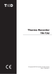
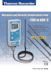
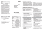
ɡ Safety Precautions and Requests ȁ
RTR-61 Warranty
*Please carefully observe the following safety measures when using our product.
To prevent any loss or damage to our customers, other people and / or property, and to ensure the proper use of our products we ask that before using our product
you carefully read, understand and follow the safety rules and precautions for our products as outlined below.
Customer's name:
Address:
ȺExplanation of Picture SymbolsȻ
ȺExplanation of SymbolsȻ
Phone No.:
These entries are actions that absolutely under no
circumstance should be taken. The taking of such an action
DANGER may cause serious personal physical damage or death.
Dealer's name:
Address:
RTR-61
CAUTION
These entries are actions that if taken may lead to physical
injury or damage to persons or things.
Phone No.:
Guarantee period
Wireless Core Temperature Data Logger
User's Manual
12 months from date of purchase
Denotes an important warning or caution. Inside or near the symbol will
appear another symbol giving details.
Ȫ EX: ȤBe careful of electrocutionȫ
Denotes a forbidden action. Inside or near the symbol will appear another
symbol giving details.
Do not use in wet areas.)
( EX:
Denotes an action that you must take. Inside or near the symbol will
appear another symbol giving details.
( EX: Unplug power plug from outlet)
Date of purchase
DO NOT POINT THE SENSOR TOWARD HUMANS OR
USE IN WAYS OTHER THAN THOSE FOR WHICH THIS
PRODUCT WAS DESIGNED
Statement of Limited Warranty
1. This product is warranted to be free from defects in materials and workmanship for a period of one (1)
year following the date of purchase. Should the product fail to operate per specification in normal use
during this period T&D will repair the unit or provide a replacement free of charge. T&D will not accept
returns for any reason other than defects during the warranty period, and will not accept any product that
has been misused, dropped, abused or inappropriately used or mistreated at any time.
2. This warranty is strictly limited to repair or replacement-in-kind for defective product. T&D makes no
other warranty, either express or implied, and will not accept liability beyond the remedies stated herein.
Specifically, T&D will not accept liability for direct, indirect, special, consequential or incidental damages
arising from the use of this product.
3. Customers wishing to submit a defective product for repair or replacement during the warranty
period should first contact the dealer from whom it was originally purchased. After receiving a return
authorization the defective product should then be packaged along with a description of the difficulties
being experienced, proof of purchase and all included accessories and materials, and return it to the
dealer. In the event of difficulty contacting the original dealer, customers should contact the nearest
authorized T&D sales representative. A list of these can be found on the company' s website, www.tandd.
com, or it can be obtained by contacting TandD US directly.
4. This limited warranty statement gives the customer specific legal rights. The customer may also have
other rights which vary from state to state in the United States, from province to province in Canada,
and from country to country elsewhere in the world. To the extent this limited warranty statement is
inconsistent with local law, this statement shall be deemed modified to be consistent with such local law.
5. For further information relating to product repair or replacement, or for other service questions after
the termination of the warranty period, customers should contact their local authorized T&D sales
representative.
Because the sensor has a sharp tip, there is a
risk of accidentally stabbing people and/or
objects. Do not use the sensor for any purpose
other than measuring the temperature of
objects for which it was designed and store in DANGER!
a safe place when not in use.
Website: http://www.tandd.com/
Please be careful when using in extreme
hot or cold environments; touching the
unit may cause burns or frostbite.
CAUTION:
Use Safety
Cover
CLEAN AND STERILIZE UNITS BEFORE AND AFTER
USE
5652-169 Sasaga Matsumoto, Nagano Japan 399-0033
Tel: +81-263-27-2131 Fax: +81-263-26-4281 E-mail: [email protected]
DO NOT TOUCH SENSOR IMMEDIATELY AFTER
MEASUREMENT
EXTREME
HOT & COLD!
DO NOT
TOUCH!
DAILY MAINTENANCE
Before and after using, please clean
to remove any substances attached
to the surface and sterilize the units in
order to prevent the growth of
bacteria.
If the unit gets dirty, wipe it with a clean
cloth dipped in alcohol; DO NOT WASH
with WATER.
NEVER use an acid, alkaline, or chlorine
based detergent. This will cause harm to
the electric components in the unit.
© Copyright 2006-2007 T&D Corporation All rights reserved.ȁ 2007.11ȁ16004394080 (1st printing)
This is printed on recycled paper.
!DANGER
!!CAUTION
We are not responsible for any damage, malfunction or trouble,
whether direct or indirect, caused by the use of our product. Please
be fully aware of this before using our product.
Do not take apart, repair or modify the main unit.
This may cause fire or electrocution.
Measurement Item
Measurement Channels
Measurement Range
Ƚ 25Ɏ to 235Ɏ
Temperature Sensor
Thermistor
Measurement Accuracy
130Ɏ to 150Ɏ : Ⱦ 1.0Ɏ
: Ⱦ 1.0Ɏ
150Ɏ to 180Ɏ : Ⱦ 1.5Ɏ
40Ɏ to 85Ɏ
: Ⱦ 0.8Ɏ
180Ɏ to 200Ɏ : Ⱦ 2.0Ɏ
85Ɏ to 110Ɏ
: Ⱦ 0.5Ɏ
More than 200Ɏ : Ⱦ 2.5Ɏ
110Ɏ to 130Ɏ : Ⱦ 0.8Ɏ
Measurement / Display Resolution
0.1Ɏ
Measuring / Display Interval
0.5sec
Number of Recorded Data
1800 data readings
LCD Display
Date and Time, Measured Value, Battery Life Warning
Unit of Temperature (Ɏ / Ȍ
F) , User, Items
Temp. Judgment LED Display
Out of Range: Red LED Blink
Within Range: Green LED Blink
Clock Resolution
Month / Day / Year / Hour / Minute / Second
Clock Accuracy
Within +/- 1 second per day (at 25Ɏ )
Battery
AAA Alkaline Batteries (LR03) x 2
(AAA Ni-Cd, Ni-MH Batteries also compatible)
Battery Life
About 1 month
(when used for PUSH recording every 10 minutes for 16 hours a day)
Interface
Wireless Communication / Optical Communication
Optical
Communication Speed
Wireless Method
Wireless Communication Speed
Wireless Transmission Range
Do not use any batteries other than those that are recommended.
- All rights of this User's Manual belong to T&D Corporation. It is prohibited to use,
duplicate and/or arrange a part or whole of this User's Manual without the
permission of T&D Corporation.
Less than 10Ɏ : Ⱦ 1.5Ɏ
It may cause fire or damage.
Continued use may cause fire, electrocution or damage.
- T&D Corporation accepts no responsibility for any malfunction of and/or trouble
with this product or with your computer that is caused by the improper handling
of this product and will deem such trouble or malfunction as falling outside the
conditions for free repair of the attached warranty.
Store all batteries, sensors and Thermo Recorder units out of the
reach of children.
2400bps
ȪWhen downloading 1 unit of full data: about 2 minutes and 30 secondsȫ
FCC Part15 Section 249, Frequency: 915MHz
When downloading 1 unit of full data: about 6 minutes
About 100m (if direct and unobstructed)
Antenna
Internal Type
Unit Water Resistance
IP64 (dust / splash resistant <rated for use in daily life>)
Dimensions
146.8mm x 40mm x 37.9mm (excluding sensor part)
Unit Weight
About 83g (Including 2 AAA batteries; excluding sensor)
Operating Environment
Ƚ 10Ɏ to 60Ɏ
- Please carefully read this User's Manual and Free Repair Warranty.
- The warranty that is included in this User's Manual cannot be reissued, so
please keep it in a safe place.
- This manual has been written using Ɏ as the standard unit of temperature.
Static electricity may cause not only damage to the unit, but may cause breaks in or
a loss of data.
The RTR-61 is a devices to measure temperature.
Do not use this unit for any purpose other than temperature measurement.
Use these units under conditions with an ambient temperature of
-10 to 60Ɏ .
The RTR-61 only becomes water resistant (IP64 splash resistant) if
the temperature sensor has been connected.
It is dangerous to swallow batteries.
!Wireless
Without the sensor connected, the connector part of neither the main unit nor the
temperature sensor is water resistant; make sure not to get wet.
Regulations
Do not expose the unit to harmful gases or chemicals.
Radio, EMC and Safety Regulations
It may cause corrosion and/or other danger to the unit and to people handling the
unit.
This device complies with part 15 of the Federal Communications
Commision (FCC) rules and with RSS-210 of the Industry Canada (IC).
Operation is subject to the following conditions:
(1) This device may not cause harmful interference, and
(2) This device must accept any interference received, including interference
that may cause undesired operation.
- Figures and illustrations in this manual may be slightly simplified and may differ
from the actual product.
- We sincerely hope that the contents of this manual are true and complete. If you
find any information to have been omitted, or if the information within is
confusing or mistaken please contact your retailer or T&D Corporation.
To prevent damage to the unit from static electricity, remove static
electricity from your body by touching metal around you (door knob,
window frame) before touching the unit.
If water or a foreign object enters the case, immediately cease using
it.
- Please follow the safety precautions carefully. We cannot guarantee nor are we
responsible for safety if this product is used in any manner other than was
intended.
- T&D Corporation accepts no responsibility for any result or effects from using
this User's Manual.
This product has been designed for private or industrial use only. It
is not for use in situations where strict safety precautions are
necessary such as in connection with medical equipment, whether
directly or indirectly.
Continued use may cause fire, electrocution or damage.
- Please read this manual carefully before using the product.
Temperature
1 Channel
40Ɏ to 10Ɏ
If any smoke or strange smells are emitted from the unit,
immediately cease using it.
ɡ Notices about this User's Manual
ɡ Product Specifications
Do not drop the unit, or expose the unit to a strong impact. If that
happens to the unit, immediately remove the batteries and stop
using.
Continued use may cause fire or electrocution.
Battery terminals may provide insufficient contact due to age or
vibration.
Note:
This equipment has been tested and found to comply with the limits for a Class B digital
device, pursuant to Part 15 of the FCC Rules. These limits are designed to provide
reasonable protection against harmful interference in a residential installation. This
equipment generates, uses and can radiate radio frequency energy and, if not installed
and used in accordance with the instructions, may cause harmful interference to radio
communications. However, there is no guarantee that interference will not occur in a
particular installation. If this equipment does cause harmful interference to radio or
television reception, which can be determined by turning the equipment off and on, the
user is encouraged to try to correct the interference by one or more of the following
measures :
This may lead to data loss.
Battery life depends on the measurement environment,
communication frequency, recording interval and battery quality.
If the unit will not be used for period of time, for safety reasons
please remove the battery.
If left in the unit, it may leak and lead to malfunctioning.
Do not use or store the unit in places such as listed below:
- Reorient or relocate the receiving antenna.
- Increase the separation between the equipment and receiver.
- Connect the equipment into an outlet on a circuit different from that to which the receiver is
connected.
- Consult the dealer or an experienced radio/TV technician for help.
-Areas exposed to direct sunlight
-Areas exposed to water or high-pressure water flow.
-Areas exposed to organic solvents and corrosive gas.
-Areas exposed to strong magnetic fields
-Areas exposed to static electricity.
-Areas exposed to fire or overheating.
-Areas exposed to excessive dust or smoke.
Warning to users
The user that changes or modifications not expressly approved by the party responsible for
compliance could void the user's authority to operate the equipment.
ɡ Temperature Sensor (Optional)
What is RTR-61?
ɡ RTR-61 Series
All-in-one Type Temperature Sensor
ɜ Thermo Recorder Push Wireless RTR-61 is a handy-type device which acts both as a thermometer and a
temperature recorder, which has been designed to easily measure and record the internal temperature of
food items and liquid temperature using a needle-type sensor.
ɜ This product has been designed to meet IP64 standards (splash resistant; rated for use in daily life).
RTR-61 measures and records core temperature, which makes it suitable for use in the food production
industry especially temperature management for HACCP.
ɜ The unit incorporates a battery life warning function, which informs the user when it is time to replace the
battery. When the battery power becomes low, all normal operations will stop in order to protect the data.
(Sensor directly attached to the RTR-61 Main Unit)
ȬUnitȇmmȭ
RTR-6110: Short Temperature SensorȁȁȁȁȁȁȁȁTR-6130: Long Temperature Sensor
Sensor Length: 125mmȁȁȁȁȁȁȁȁȁȁȁȁȁSensor Length: 300mm
Separate Type Temperature Sensor
(Sensor with Handgrip and Cord. Easy to measure temperature, even in steam.)
ɜ The LCD Backlight allows the display to be easily read even in low light. The LCD contrast can also be
easily adjusted for better viewing.
ӱ RTR-61-110ȇAll-in-One Short Type Set
ȬUnitȇmmȭ
ɜ These units are also designed with short range wireless functions that when coupled with our exclusive
software set "Push Wireless Communication Set (RTR-61SK)", makes it possible to carry out wireless
communication, allowing for easy and effective management of multiple RTR-61 units.
Package of Contents
AAA Alkaline Batteries
(LR03) x 2
RTR-61 Main Unit
(Sensor attached)
ȁMain Unit (RTR-61) + All-in-One Short Type Sensor (RTR-6110)
RTR-6210: Short Temperature Sensor ȁȁȁȁȁȁȁȁRTR-6230: Long Temperature Sensor
Sensor Length: 125mm / Cord Length: 900mmȁȁȁSensor Length: 300mm / Cord Length: 900mm
Ӳ RTR-61-130ȇAll-in-One Long Type Set
ȁ Main Unit (RTR-61) + All-in-One Long Type Sensor (RTR-6130)
ӳ RTR-61-210ȇSeparate Short Type Set
ɜ Sensor Materials: Stainless pipe(SUS316)ȁ
ɜ Handgrip Materials: Polysulfone Resin (Temperature Durability: About 170Ɏ ) ȁ
ɜ Cord : Teflon® Resin(FEP) Shielded
ɜ Common Items Included: Sensor Spacer 1 / Rubber Packing 1 / Sensor Replacement Tool 1 / Sensor User's Manual 1
*Teflon® is a registered trademark of U.S. company Du Pont.
ȁ Main Unit (RTR-61) + Separate Short Type Sensor (RTR-6210)
Ӵ RTR-61-230ȇSeparate Long Type Set
ȁ Main Unit (RTR-61) + Separate Long Type Sensor (RTR-6230)
*Common Items Included:
2 AAA alkaline batteries, User's Manual (this document)
User's Manual
Warranty
(this document)
ӱȁInstalling Batteries
Read the following for details about battery life and battery installation.
Part Names and Functions
ɡ Battery Life Indicator
Judgment LED (Red / Green)
Temperature Sensor
The Judgment result of temperature
measurement will be shown. Out of Range:
Red LED will blink. Within Range: Green LED
will blink.
The battery indicator on the LCD display allows you to view the status of the battery life. If the remaining battery power becomes
zero, a battery replacement message will appear. Once the message appears, please change the battery as soon as possible.
As for details about how to remove or change
the sensor, please see the User's Manual that
comes with the sensor you will be using.
Please be careful when handling the
temperature sensor.
ɖ Judgment LED Settings
By changing settings, it is possible to turn ON or
OFF the Judgment LED function.
PUSH Record LED (Orange)
LCD Display
By pressing the <REC> button, the lamp will
turn on when a temperature measurement is
recorded.
The RTR-61 is designed with a graphic LCD
display with a resolution of 132 x 64 pixels.
* The recorded object is the temperature at the
instant when the <REC> button is pressed.
ɖ Backlight Function
The LCD Backlight makes the display easier to
read in low light conditions.
<REC> Button (Record)
ɖ Contrast Adjustment Function
The display contrast can be adjusted here.
<MENU> Button
By pressing this button, the Menu will be
displayed. Also, press to return to the previous
window.
<ENT> Button
Press to enter the settings menu or determine
the settings.
˝
When this button is pressed, the
Temperature, Date / Time, User Name, Item,
and Judgment Result at the time of pressing
are recorded into the RTR-61.
A battery replacement message will appear. If the
batteries are further left, LCD display goes blank.
ŏŐŕņ
-If the LCD display goes blank and batteries are further left unchanged, recorded data may be erased. Please replace the batteries as soon as possible.
-Make sure that the + and – are in the correct direction. If the battery terminals + / - are mistaken and a short occurs, all data stored in the main unit will be erased.
-When opening the battery case to change the batteries, make sure no water or foreign object gets inside the case.
-Make sure to change both batteries at the same time and use two batteries of the same type.
ӱ Insert the top
end of the cover
into the unit
Cursor Buttons (Moving Up and Down)
Ӳ Push it down until you
hear a clicking sound
Ӳ Lift up
Press to move the Cursors up and down on
the display.
ӱ Push
Power Button
Press to turn on / off the power.
ɖ Automatic Power-OFF Function
If the unit is not used for about five minutes, it will
automatically turn off.
ɖ Automatic Power-ON Function
ȁȁ ˝ Ȥ Optical Communication Area for communication
with the Base Unit (RTR-50 / RTR-5W).
If the unit gets dirty, wipe it with a clean cloth
dipped in alcohol.
Battery Life
Indicator
ɡ Installing the Batteries
If a unit is OFF, when wireless or optical
communication is carried out by a Management
Operator, that unit will be automatically turned ON.
1.
2.
3.
Open the RTR-61 by pushing up
on the bottom of the battery case
on the back of the unit.
Insert 2 AAA alkaline batteries, making
sure that the + and – are in the correct
direction. (The + of two batteries should
face toward the bottom of the case).
Be sure to securely close the cover until
you hear a clicking sound.
ӲȁOperations Table
ӴȁAbout PUSH Recording Window
This is a table of operations for RTR-61. When using, please refer to the following chart.
This window will appear by pressing the <REC> button on the RTR-61 unit to record temperature.
ɡ Recorded Temp
ɡ Wait for Temp
(Displayed normally after PUSH Recording)
PUSH Record LED "ON"
2ECORDED4EMP
#UTLET
(Measuring in progress and waiting for the constant temp)
If the "Wait for Constant Temp Function"
has been applied to your RTR-61 unit by
the Management Operator, this message
will be displayed while waiting for the
temperature measurement to stabilize.
The recorded temperature
is displayed for about three
seconds; after which the unit
returns automatically to the Top
Window.
Do not remove the sensor while "Wait for Temp" is on display
and the PUSH Record LED is blinking.
- If the Button Sound has been set to "ON", the unit beeps when recording
temperature.
- When the "Wait for Constant Temp Function" is active, the temperature will not be
recorded until temperature stabilization has been achieved. Due to this, after
pressing the <REC> button it may take some time before the temperature is actually
recorded.
- If the temperature is not stabilized after 15 seconds have elapsed, recording will not
be performed and you will be returned to the Top Window.
- If the Button Sound has been set to "ON", the unit beeps both when the "Wait for
Temp" operation has been started and when the temperature has been recorded.
ӵȁMenu Contents
Details about the Main Menu and the Operational Settings Menu are as follows.
Menu
Settings Window
Details
Data List
Check Data
All recorded data is displayed in descending order (from the newest to the
oldest data). Specify data by moving cursors and press the <ENT> button to
view detailed information.
The 83rd data reading is
highlighted by the cursor.
Check Data
Data details (Date/Time of Recorded Data, Measurement Item, User Name,
Temperature, and Judgment Result) can be viewed.
ȤJudgment OKȁȁ ȤLower Limit Error ȁȁ ȤUpper Limit Error
Judgment Result
Select User
Select and set the User Name of the person who will measure and record
temperature. If User Registration has been made by creating Groups from a
Base Unit, first, select the Group Name from the list in the [Select User Group]
window. Then select the User Name from the list in the [Select User] window.
Select Item
Select and set the Measurement Items. If User Registration has been made
by creating Groups from a Base Unit, first, select the Group Name from the list
in the [Select Item Group] window. Then select the User Name from the list in
the [Select Item] window.
ӳȁMain Window Names and Functions
See the following for the items displayed in the Top Window and the Main Menu Window.
User Item
ɡ Top Window
ɡ Main Menu Window
By turning the Power ON, the Top Window will appear. Following are
the main display items and marks that appear in the Top Window.
While the Top Window is being displayed, pressing the
<MENU> button on the face of the unit will display the Main
Menu.
ӱ
It is possible to turn ON / OFF the blinking of Upper and Lower Limit Judgment
LED.
ӱ
ӵ
Ӷ
ӳ
ӹ
Ӹ
Button Sound
It is possible to turn ON / OFF the beep which sounds when pressing a button.
Ӳ
ӷ
ӳ
Ӵ
Backlight
ӱ Title:
ӱ Current Date /Time:
Ӳ Cursor:
Select the item by moving the Cursor up and down by pressing the
arrow buttons <
> on the face of the unit.
Press the <ENT> button on the face of the unit to select the desired
menu.
Press the <MENU> button on the face of the unit to return to the
previous window.
Ӳ User Name :
By pressing the <REC> button, the user whose name is shown here will be
recorded as the person who is making the temperature measurement. ȃ
ӳ Item :
Unit of Temp.
Select Fahrenheit [ɋ
F] or Celsius [Ɏ ].
ӳ Highlight:
By pressing the <REC> button, the item name shown here will be recorded as
the measurement item whose temperature is being measured and recorded.
While the <ENT> button is pressed, the Group Name to which the Item belongs
will be displayed.
The cursor selected item is displayed in white letters on a black
background.
Ӵ Scroll:
Ӵ Current Temperature :
Contrast
The scroll up and down arrows show that data exists outside of the
display area.
> button on the face of the unit to scroll up.
ɣȤ Press <
ɥȤ Press <
> button on the face of the unit to scroll down.
The currently measured temperature will be displayed.
It is possible to adjust the contrast of the display.
]:
The symbol displayed here shows Recording Mode. It is not possible to make
Recording Mode settings from an RTR-61 unit. The Clock Settings can be made
from the Base Unit (RTR-5W / RTR-50) by the Management Operator using
Wireless or Optical Communication.
ӷ Wireless Communication in Progress [
The Backlight factory default setting for the RTR-61 is "ON in Use", which will
backlight the window for 3 seconds only when in operation. Here you can shift
the setting to "Always ON" or "Always OFF".
The title of the menu will be displayed.
The current date and time (Month / Date / Hour / Minute) will be displayed. It is
not possible to make clock settings from an RTR-61 unit. The Clock Settings
can be made from the Base Unit (RTR-5W / RTR-50) by the Management
Operator using Wireless or Optical Communication.
ӵ Unit [
]:
Select from Fahrenheit / Celsius.
Ӷ Recording Mode [Endless
Onetime
Remote Info
Before carrying out wireless communication, it is necessary for the
Management Operator to register RTR-61 units as Remote Units and register
them into Groups. The Group Name and Remote Unit Name can be viewed
here for the RTR-61 unit being used.
Memory Usage
Each RTR-61 can record and store up to 1,800 of data readings. The number
of stored data can be viewed here.
]:
While wireless communication is occurring, this mark will appear.
Ӹ Battery Status [
- While the <ENT> button is pressed in
the Top Window, the Group Name to
which the Item belongs will be
displayed.
Judgment LED
Set Operation
Ӳ
Ӵ
Item Group
]:
The remaining amount of battery power will appear.
ӹ Remote Mode[
]:
The recording of temperature measurements is being controlled by wireless
communication.
Depending on the settings, some operations are restricted from being carried out by manipulating
132 of data readings
are recorded.
the buttons on the unit. Refer to the following for details:
ɡ Remote (Remote Mode)
1.
When an RTR-61 unit has been set to "Remote Mode"
by the Management Operator, it is not possible to use
the "PUSH Recording" function without first receiving
a "Measurement Command" from the Operator. Even
while the power is OFF, when an RTR-61 unit receives a
"Measurement Command", the LCD backlight will begin
to flash and a beeping sound will notify the user that it is
time to carry out a recording.
To record a measured temperature while in Remote
Mode, please carry out the following procedures:
Measurement Command
Message example
When a Measurement Command is
received, push the <ENT> button on
the face of the unit to return to the
Top Window.
*The backlight blinking and beeping sound
will continue until the <ENT> button is
pressed.
2.
3.
Top Window
When the display switches to the
Top Window, the specified item will
be on display.
Please measure and record the
temperature of the specified item.
ӶȁAbout Message Display
Even when the power is OFF, an automatic Power-ON may occur to display a message.
ɡ Created Messages
- By making the backlight light up or the beeping sound occur, the user can be
informed that a message has been received.
- Messages can be received regardless of any mode settings in the RTR-61.
- Note that there is no message storing function, so messages will not be
redisplayed once you press the <ENT> button.
ɡ FULL when in One-time Mode
ɡ Settings Change Messages
If any settings changes have
been made via wireless / Optical
communication to the RTR-61 unit in
use, a notification message will be
displayed for about two seconds. After
that, you will be automatically returned
to the Top Window.
The RTR-61 unit can receive
any created message from the
Management Operator. They will
continue to be displayed until the
<ENT> button on the face of the
unit is pressed.
- Messages will be displayed regardless of any mode settings in the RTR-61.
ɡ Button Lock Function
ӷȁMeasurement Error Messages
If a temperature measurement error occurs, there may be a poor sensor connection. In such a case,
an Error Message will appear.
This symbol shows that the data recording capacity is full
and no more new data can be recorded. In order to carry out
recording again, it is necessary to first download the recorded
data from the RTR-61 to the manager's computer and then
delete it from the unit.
Because the Management Operator has placed a restriction
on carrying out direct operations using the RTR-61, only the
<REC> and <POWER> buttons are operable.
- Note that if a Message (see Section Ӷ ) or a Measurement command is
received from the Management Operator, the <ENT> button will become
operable.
Check the sensor
connection.