1
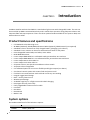
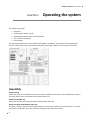
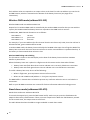
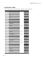
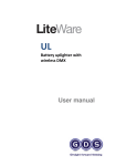
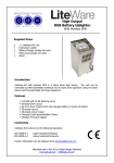
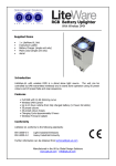
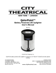
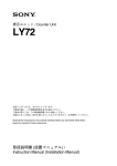
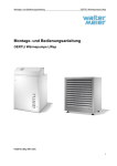
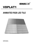
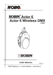
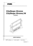
Satellite
High output battery
uplighter with wireless DMX
and interchangeable
RGB/white heads
User manual
LiteWare Satellite User manual
Manufactured in the UK by Global Design Solutions
Web www.gds.uk.com Email [email protected] Tel +44 (0)117 325 0063
Patent information
LiteWare charging apparatus: UK Patent No. GB2473474B · US LiteWare charging apparatus: Pat.
pending US12/598,330 · LiteWare V2: Pat. pending GB1103835.3 · Lighting apparatus: Pat. pending
GB1107353.3 · LiteWare: EU Reg’d Design 001600362-0001 · LiteWare Charger Case: EU Reg’d Design
001774555-0001 · LiteWare US Pat. USD616,579.
Firmware versions
This manual refers to features available in firmware version 2.56. This firmware version is valid from: 1
November 2011. The firmware can be upgraded in LiteWare HO and Satellite units with a serial
number higher than 3651, using a GDS wireless firmware updater unit (please contact your GDS
International Sales Manager for enquiries regarding this device). LiteWare units with a serial number
lower than 3651 cannot be upgraded due to incompatible hardware. User manuals for older firmware
versions are available on the GDS website.
Conformity
LiteWare Satellite conforms to the following standards:
EN 61000-6-3: Light Industrial Emissions
EN 61000-4-2: Heavy Industrial Immunity
Further information can be obtained from [email protected]
2
LiteWare Satellite User manual
Contents
CHAPTER 1
Introduction ........................................................................................................... 4
System options ................................................................................................................................... 4
Product features and specifications .................................................................................................... 4
Weights and dimensions ..................................................................................................................... 5
Conformity .......................................................................................................................................... 2
CHAPTER 2
Charging the system ............................................................................................... 6
Flight case charger system .................................................................................................................. 6
Single unit charger .............................................................................................................................. 6
Low battery ......................................................................................................................................... 6
Battery care ........................................................................................................................................ 6
CHAPTER 3
Operating the system ............................................................................................. 8
Assembly............................................................................................................................................. 8
Changing heads.............................................................................................................................. 9
Switching the system on/off ............................................................................................................... 9
Operating modes ................................................................................................................................ 9
Wireless DMX mode (address 001-512) ....................................................................................... 10
Stand-alone mode (addresses 601-670) ...................................................................................... 10
The controls and display ................................................................................................................... 12
UP and DN buttons ...................................................................................................................... 12
The address display panel ............................................................................................................ 12
Personalities ..................................................................................................................................... 13
Channel assignments for P3 mode (6-channel) ............................................................................ 13
Channel 6 control channel DMX values........................................................................................ 13
Fixed colour table ............................................................................................................................. 14
CHAPTER 4
Troubleshooting ................................................................................................... 15
CHAPTER 5
Safety information ............................................................................................... 16
3
LiteWare Satellite User manual
CHAPTER 1
Introduction
LiteWare Satellite with wireless DMX is a stand-alone light source with changeable heads. The unit can
be controlled by DMX transmitted wirelessly and in stand-alone operation using 50 preset colours and
20 preset fade and snap sequences. There are three optional heads available for the system: RGB, cool
white and warm white.
Product features and specifications
•
•
•
•
•
•
•
•
•
•
•
•
•
•
•
•
•
•
•
•
•
•
•
•
•
Full RGB with 16-bit dimming curve
W-DMX (standard), SHoW DMX and Lumen Radio (optional), CRMX control (not required)
Standard 14 hour runtime from fully charged battery (charging cycle 6 hours)
Standard 5 hour runtime on the warm white and cool white on full power
Interchangeable heads: RGB; cool white; warm white
80 W RGB LED emitter
Lumen output RGB 1650 lm in calibrated mode, personalities zero and one
Lumen output RGB 1800 lm in un-calibrated mode, personalities two and three
Lumen output warm white 2821 lm
Lumen output cool white 4251 lm
50 preset colours, two-thirds Lee and Rosco colour swatch
20 preset colour snaps/fades
Un-calibrated option for more user flexibility and higher output (see above)
Six-channel control option with master fade and preset recall
Finished in mirrored stainless steel to blend in with any surrounding
Integral rugged aerial design
IP45 – interior/exterior use
Weatherproof design
Available singularly or in flight cases with inbuilt charging
Kensington Security lock ready
Easily upgradable firmware on all models
Low heat
No cables
No 230 Volt
Made in UK
System options
On LiteWare Satellite all of the below are options.
4
Part code
Part
LWSBB
Battery base unit
LiteWare Satellite User manual
Part code
Part
LWSHRGB
Head unit, RGB
LWSFP
Floor plate
LWSP
Pole
LWSBAG
Pole bag (four-way)
LWGC
Grindle cap
LWSFC4
Flight case (four-way)
Alternative head units:
LWSHWW
Head unit, warm white (3,000 K)
LWSHCW
Head unit, cool white (4,100 K)
Pole
TOP button
Head
Battery base
unit
Floor plate
Weights and dimensions
Part
Weight, kg
Dimensions, cm
Battery base unit
13.2
Height: 35.0, Depth: 17.9, Width: 18.2
Head
2.4
Length: 16.8, Height: 10.3, Depth: 13.2
Pole
1.4
Length: 131.0, Diameter: 5.7
Floor stand
2.2
Width: 40.0, Height: 34.5, Depth: 2.6
Flightcase (empty)
50.7
Length: 79.0, Width: 50.0, Height: 75.0 (incl. wheels).
5
LiteWare Satellite User manual
CHAPTER 2
Charging the system
There are two charging methods available for LiteWare Satellite.
• flight case charger system
• single unit charger
Both charger options are designed specifically for LiteWare Satellite. Please DO NOT use any other
charging system as this can damage the battery base unit. The charging cycle is approximately six
hours.
Flight case charger system
1 Ensure that the flight case is plugged into a mains supply with the supplied mains lead.
2 Place the LiteWare Satellite into the flight case. The battery base unit starts charging. During
charging, the button LED is on constantly. The battery is fully charged when the button LED
flashes. LiteWare Satellite is now ready for use.
Upon disconnecting mains power to the flight case, all charged battery base unit s continue to flash
the button LED. This is normal. To switch this flashing button LED off, briefly lift the battery base unit
out of the case and replace.
Single unit charger
Plug the supplied charger into the base of the battery base unit. During charging, the button LED is on
constantly. The battery base unit is fully charged when the button LED flashes.
Note: If you leave the LiteWare Satellite connected to the single charger without the charger
connected to mains power the battery will flatten.
Low battery
When the battery voltage becomes too low, the battery base unit goes to sleep and the TOP button
LED flashes at a fast rate. You must recharge the battery base unit before you can use it again.
Battery care
The LiteWare Satellite Uplighter contains a sealed lead-acid battery. The battery should not be left in a
discharged state for long periods because this will reduce its capacity. We recommend leaving
LiteWare Satellite on charge permanently when not in use.
Note: If you remove the battery, please observe the correct polarity upon reconnection.
The following points should help maintain the long life of your LiteWare battery:
6
LiteWare Satellite User manual
• When in use, LiteWare automatically switches off when the battery voltage reaches a set lower
limit. This is to avoid any deep discharge damage of the battery. It is not recommended that
LiteWare batteries be left for any prolonged period in this state.
• LiteWare should always be fully re-charged as soon as possible. Once fully charged LiteWare
can be stored.
• If LiteWare is to be unused for long periods, we recommend LiteWare is charged every two
months to keep the batteries topped up.
• If LiteWare is stored in hotter environments (above 20 degrees), we recommend a monthly
storage charge.
• From market data, the estimated number of uses in a normal environment is around 200 cycles.
This may be higher if LiteWare is not run to ‘turning off automatically’ every time. We
recommend replacing LiteWare battery every two years.
7
LiteWare Satellite User manual
CHAPTER 3
Operating the system
This chapter describes:
•
•
•
•
•
Assembly
Switching the system on/off
Operating modes (wireless and standalone)
The controls and display
Personalities
Full operating instructions are provided in this chapter. In addition, the bottom of the battery base
unit has a label with various operational and safety information. Below is a schematic of the label:
Assembly
Attach a head
Heads can either be inserted directly into the top of the battery base unit or can be attached on top of
the pole, which in turn is attached to the battery base unit.
Attach the Grindle cap
Attach the Grindle cap to the top section of the battery base unit.
Attach the pole to the battery base unit
The pole is simply inserted into the battery base unit. The head is placed on top of the pole. To release
the head from the pole, press the small release button then extract the head.
8
LiteWare Satellite User manual
Adjust the pole length
To adjust the pole length, twist the collar anticlockwise to loosen the joint, then slide the two sections
of the pole apart or together to lengthen or shorten, respectively. Do not to extend the pole past the
red marker, which indicates full extension. Twist the collar clockwise to tighten the joint.
Attach the battery base unit to the floor plate
Once the battery base unit has been configured with the desired channels, it should be attached to the
floor plate for stability.
1 Place the battery base unit on the floor plate with the four holes on the battery base unit
aligned with the four lugs on the floor plate.
2 Loosen the clamp mechanism on the floor plate using the black knob.
3 Slide the clamp mechanism across so that the four lugs pass into the four holes of the battery
base unit.
4 Tighten the clamp mechanism using the black knob.
Changing heads
If you change heads to a different type (RGB or white head), and then power the battery base unit off
then back on again, the battery base unit detects whether the head is of a different type and the
addresses of the control channels change accordingly, reinstating the last address used for that head
type.
For example:
1 Let’s say the battery base unit is set to address 401 with an RGB head.
2 You change the head to a white head.
3 You power off the battery base unit then power on again. The address changes to the last
address used for that head type (or a default value if an address for that head type is not stored
in the battery base unit).
4 You reattach the RGB head. Power off then on again. The address of 401 is reinstated.
Switching the system on/off
Press and hold the TOP button for 1.5 seconds. The button LED switches on to show the battery base
unit is on. Press and hold the TOP button again to switch off.
On powering up, the battery base unit automatically detects which type of head (RGB or white) is
attached. When using the RGB head, a brief flash of red is observed, and then the battery base unit is
ready for use.
Operating modes
There are two operating modes:
• Wireless DMX mode (uses addresses in range 1-512)
• Stand-alone mode (uses addresses in the range 601-670)
9
LiteWare Satellite User manual
Each address value corresponds to an output colour at the head. To select an address you use the UP
and DN buttons, which are situated on the bottom of the battery base unit (see page 12 for
instructions).
Wireless DMX mode (address 001-512)
Wireless DMX mode uses addresses 001-512.
Output level in wireless DMX mode is controlled by the wireless DMX controller that you use with the
system; the LiteWare Satellite battery base unit responds to the DMX levels it receives.
In RGB mode, DMX channel allocations are as follows:
Start address
Start address + 1
Start address + 2
red level
green level
blue level
For example, if your start address (the first channel that the unit listens to) is 001, then the red level is
allocated to 001, green to 002 and blue to 003.
In wireless DMX mode, the battery base unit holds the last DMX value upon loss of signal or DMX. The
battery base unit stores this level when turned off so it can be resumed when it is powered back up. If
the battery is disconnected these values are lost.
Wireless DMX linking and unlinking
The link status is shown on the LED display on the base of the battery base unit when LiteWare
Satellite is powered on.
When the battery base unit is placed in a flight case the link status can be observed as follows:
•
•
Battery base units flash blue three times to indicate unit is currently linked to a transmitter.
Battery base units flash green three times to indicate unit is not linked to a transmitter.
To unlink a battery base unit, do one of the following:
• When in flight case, press top button 3 times to force unlink.
• When on and in DMX mode (address 1 – 512) press top button 3 times.
The DMX buffer is cleared when unlinked to prevent any confusion when the unit is not linked to a
transmitter.
Refer to your W-DMX transmitter user manual for further information about the linking process.
Stand-alone mode (addresses 601-670)
Stand-alone mode uses addresses 601-670.
To control the output level, press the TOP button briefly: each time you press the TOP button the
output is dimmed by a fixed amount. There are seven output levels. When the TOP button is pressed
for the seventh time, the output returns to full level.
The table below describes the address ranges available in stand-alone mode.
10
LiteWare Satellite User manual
Range
What
Description
601-650
Fixed colours
The fixed colours are listed in ‘Fixed colour table’ on
page 14.
651-655
Colour fade sequence 1
A sequence of pre-programmed colour fade
transitions using brilliant colours. The higher the
address value, the slower the rate of transition.
656-660
Colour fade sequence 2
As ‘Colour fade sequence 1’ but using pastel colours.
661-665
Colour snap sequence 1
A sequence of pre-programmed colour snaps using
brilliant colours. The higher the address value, the
slower the rate of transition.
666-670
Colour snap sequence 2
As ‘Colour snap sequence 1’ but using pastel colours.
Approximate run times for Satellite with white head
Percentage of
maximum output
Number of pushes
of top button
100
Run time
(hours)
4.5
90
1
5.0
80
2
7.0
70
3
12.5
60
4
13.0
50
5
19.0
40
6
26.0
Run times for Satellite with RGB head when on full white
Percentage of
maximum output
Number of pushes
of top button
100
Run time
(hh:mm)
7:21
90
1
7:53
80
2
9:58
70
3
13:35
60
4
17:48
50
5
27:38
40
6
67:21
11
LiteWare Satellite User manual
The controls and display
On the bottom of the battery base unit are the UP and DN buttons, and the ADDRESS display panel.
UP and DN buttons
The UP and DN buttons are used to select an address.
Button
Behaviour
UP
Increments the address by 1.
DN
Decrements the address by 1 (001 is the lowest value).
Tip: The casing of the battery base unit is cut away at the bottom which allows these buttons to be
reached even when the battery base unit is standing vertically upright.
Fast address searching and address boundaries
If you press and hold the UP or DN button the address changes slowly then gradually speeds up. When
the end of an address range is reached (see below) the address stays at that value. To select an
address in the next range, release the button then use the UP or DN button again.
Fast searching and address ranges provide an easy way to select addresses quickly. The address ranges
for both wireless DMX and stand-alone modes summarised in the table below. See page 14 for
detailed descriptions of the stand-alone address ranges.
Range
What
001-512
Wireless DMX mode address
601-650
Fixed colours (stand-alone mode)
651-655
Colour fade sequence 1 (stand-alone mode)
656-660
Colour fade sequence 2 (stand-alone mode)
661-665
Colour snap sequence 1 (stand-alone mode)
666-670
Colour snap sequence 2 (stand-alone mode)
The address display panel
The address panel displays the current address. The display goes mostly blank after five seconds of
button inactivity.
When the display goes mostly blank, there are a few small LED point indicators that show information
about the state of the battery base unit. These are described in the table below.
12
Indicator
Description
POWER
Shows whether the battery base unit is on or off.
RADIO DMX LINK
Shows when a radio DMX link is present.
LED DRIVE
Shows when a channel is ‘on’.
LiteWare Satellite User manual
Personalities
To access personalities press and hold the UP and DN buttons simultaneously until the display reads
“Per”. The battery base unit is now in Personality mode.
To choose a personality use the UP and DN buttons (single presses, as for selecting normal addresses).
Either wait for the display timeout or press the TOP button to accept the personality.
There are four personalities available, from P0 to P3:
Personality
ID
Description
P0
Mimics the ‘Snap Off’ featured in LiteWare HO RevA.
P1
Calibrated (balanced white) 3-channel RGB control without snap off.
P2
Uncalibrated 3-channel RGB control without snap off.
P3
6-channel DMX mode.
Channel assignments for P3 mode (6-channel)
Channel 1: Red intensity
Channel 2: Green intensity
Channel 3: Blue intensity
Channel 4: Master intensity
Channel 5: Static colour select (see ‘Fixed colour table’ on page 14)
Channel 6: Control channel (see ‘Channel 6 control channel DMX values’ below)
Channel 6 control channel DMX values
Function
Min
Max
Calibrated
0
49
Uncalibrated
50
99
Spare
100
149
Spare
150
199
Spare
200
255
13
LiteWare Satellite User manual
Fixed colour table
Address values and colours of the ‘fixed colours’ (addresses in the range 601-650):
Address
601
602
603
604
605
606
607
608
609
610
611
612
613
614
615
616
617
618
619
620
621
622
623
624
625
626
627
628
629
630
631
632
633
634
635
636
637
638
639
640
641
642
643
644
645
646
647
648
649
650
14
Colour
RED
GREEN
BLUE
YELLOW
CYAN
MAGENTA
ORANGE
GOLD
PINK
VIOLET
AQUA
SKY BLUE
FULL WHITE
COOL WHITE
WARM WHITE
YELLOW
STRAW
ORANGE
PRIMARY RED
LIGHT ROSE
DARK PINK
MAGENTA
BLUE
MED BLUE GREEN
DARK BLUE
BRIGHT PINK
MEDIUM BLUE
GOLDEN AMBER
DEEP GOLDEN AMBER
PALE LAVENDER
APRICOT
DARK LAVENDER
CHOCOLATE
JUST BLUE
SURPRISE PINK
SCARLET
SURPRISE PEACH
FIRE
ENGLISH ROSE
MAUVE
BRIGHT BLUE
ALICE BLUE
ROSE INDIGO
URBAN BLUE
COOL BLUE
LIGHT SALMON
MAYAN SUN
CHERRY ROSE
FLESH PINK
SKELTON EXOTIC SANGRIA
LEE ref
ROSCO ref
LEE 101
LEE 103
LEE 105
LEE 106
LEE 107
LEE 111
LEE 113
LEE 115
LEE 116
LEE 119
LEE 128
LEE 132
LEE 134
LEE 135
LEE 136
LEE 147
LEE 180
LEE 156
LEE 079
LEE 194
LEE 024
LEE 017
LEE 019
LEE 108
LEE 126
LEE 141
ROSCO 378
ROSCO 358
ROSCO 081
ROSCO 066
ROSCO 030
ROSCO 318
ROSCO 332
ROSCO 034
ROSCO 039
LiteWare Satellite User manual
CHAPTER 4
Troubleshooting
I can only get turquoise, not all the colours
When using an RGB head you only see turquoise and you can’t access all the addresses.
This happens when you start up the battery base unit with the white head or no head attached, and
then you connect the RGB head without powering it off and on again. When the battery base unit is in
white mode it drives the green and blue channels together creating the turquoise colour.
Power off the battery base unit then power on again.
There’s nothing on the display
The display goes mostly blank after about five seconds to save power. Press either the UP or DN
button to wake the unit up.
15
LiteWare Satellite User manual
CHAPTER 5
Safety information
Warning! Class 2M LED product. Do not look into the beam from a distance of less than
40 cm (16 inches). Do not stare into the beam for extended periods at a short distance.
Do not view the beam directly with optical instruments.
This product is for professional use only. It is not for household use. This product
presents risks of severe injury or death due to fire hazards, electric shock and falls.
READ THIS MANUAL before installing, powering or servicing the fixture, follow the
safety precautions listed below and observe all warnings in this manual and printed on
the fixture. If you have questions about how to operate the fixture safely, please
contact Global Design Solutions, www.gds.uk.com
PROTECTION FROM FIRE
Provide a minimum clearance of 0.1 m (4”) around fans and air vents.
Do not modify the fixture or install other than genuine GDS parts.
Do not stick filters, masks or other materials directly onto LEDs.
Do not operate the fixture if the ambient temperature (Ta) exceeds 40 °C (104 °F).
PROTECTION FROM INJURY
The LED emission presents a hazard to eyesight at a distance of 4–40 cm (1.6–16”)
when the eye is exposed to the beam for longer than 0.25 seconds.
• Do not look at LEDs from a distance of less than 40 cm (16”) without suitable
protective eyewear.
• Do not look at LEDs with magnifiers or similar optical instruments that may
concentrate the light output.
INSTALLATION
Install fixtures on a level, stable surface where they do not present a hazard of tripping
or falling.
OUTDOOR USE
If used outside, the unit must be dried after use. Do not use in damp conditions for
more than 24 hours at a time.
DISPOSING OF THIS PRODUCT
Global Design Solutions products are supplied in compliance with Directive 2002/96/EC of the
European Parliament and of the Council of the European Union on WEEE (Waste Electrical and
Electronic Equipment), as amended by Directive 2003/108/EC, where applicable.
Help preserve the environment! Ensure that this product is recycled at the end of its life. Your supplier
can give details of local arrangements for the disposal of Global Design Solutions products.
16