1
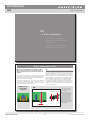
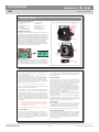
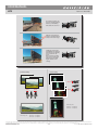
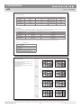
USER MANUAL HTS Item no: 3043400 Hasselblad HTS 1.5 – Introduction What is it ? The HTS 1.5 is an accessory for H-system cameras that greatly expands their usability both technically and creatively. It works by allowing a lens to be moved in two different ways to meet some challenges typically found in professional photography. It is compact, simple to use and can prove to be an invaluable aid in certain situations. The HTS 1.5 adapter is mounted between the lens and the camera body and, by way of the databus connections, automatically conveys data to ensure the optimum in convenience and accuracy of exposure. This information is finally stored as metadata with each file that can then be accessed in Phocus. And it is in Phocus that DAC corrections automatically take into account all tilt, shift and rotational movements as well as a long list of specific lens data. This ability, unique to Hasselblad, ensures the exceptional quality produced by the HTS 1.5. To be able to allow such movements using a lens from the standard range, an optical converter that increases lens coverage is integrated into the design. In this way the adapter expands the use of a number of lenses that many users already have thereby avoiding the need for dedicated lenses. Very simply put, tilting the lens moves the orientation of the plane of sharp focus while shifting the lens moves the projected image circle inside the camera. What problems does it solve? There are basically two areas that can be helped by tilt and shift: · Tilt is used when you want to change the orientation of the plane of sharp focus. · Shift is used to change the area selected for coverage of a scene while retaining parallel lines in the image. It can also used to create panoramas when used horizontally. Although tilt is typically used in close-up product or landscape photography and shift is typically used in architectural applications, it would be wrong to highlight these areas too much. There are many situations where some tilt or some shift or both would go a long way in producing a competitive edge on an otherwise normal shot. What does it do? The HTS 1.5 primarily solves problems but equally well promotes creative opportunities to provide the photographer with an almost invaluable tool. Problem solving would be most obviously beneficial in architectural work, close-up product photography and certain kinds of documentation, for example. Creative opportunities would cover almost any area of photography where a fresher approach is required regarding selective focus and/or perspective manipulation. How is it creative? How does it work? The actions that produce practical solutions to problems create effects that can also be classified as creative, dependent on the intention. For example, it might be said that “stitching” (the digital combining of several images) creatively exploits the ‘correct’ use of movements while selective de-focusing creatively exploits the ‘incorrect’ use. It exploits established optical principles familiar to view camera users, namely ‘tilt’ and ‘shift’. These capabilities are further exploited by being able to rotate the whole unit. Only basic explanations are included here as In-depth technical descriptions are beyond the scope of this manual. A search on the Internet under headings such as ‘camera movements’ and ‘Scheimpflug Principle’, for example, can provide much more insight into the concepts. 1 TILT and shIfT adapTer MOVeMenTs - rOTaTIOn The hTs 1.5 adapter can be rotated 90 degrees to the left or right to enable free placement of sharpness plane and shift direction. 20º 36mm 180º total total total Tilt Shift Rotation Tilt changes the orientation of the plane of sharp focus. This creates the appearance of an ‘increase’ or ‘decrease’ in depth of field. Shift allows perspective control by preserving parallel lines in the image. It also allows ‘stitched’ panoramas. Allows the whole unit, at any tilt and shift settings, to be rotated for further control. Compatibility The integral converter in the HTS 1.5 alters the angle of view (in effect, extending the focal length) of each lens and causes some loss of speed. For example, a HC 2.8/80mm - HTS 1.5 combination will produce an image you might expect from a 4.5/128 mm lens on its own, as a rough guide. Please see under Specifications for full details. The HTS 1.5 was specifically designed for use with the HCD 4/28mm and HC 2.8/80mm lenses, and these should be seen as the primary choice for maximum performance. However, the HC 3.5/35mm, HC 3.5/50mm and HC 2.2/100mm lenses can also be used with excellent results. The 13mm, 26mm and 52 mm extension tubes are also compatible with all of these lenses. The HC 3.2/150, HC 4/210 and HC 4.5/300 can also be used but handling and performance are compromised and are therefore not recommended for critical work. Please note that the HTS 1.5 is not compatible with the H1.7x converter, CF lens adapter, HC 3.5-4/50-110mm, HCD 4-5.6/35-90mm, or the HC 4/120mm Macro. The autofocus and focus confirmation features on the camera are also automatically de-activated for all lenses. www.hasselblad.com For the HTS to function correctly, the firmware in the camera and Phocus soft- ware must be recent. Please ensure you have the latest versions installed. You can download them free of charge from: http://www.hasselblad.com/service--support/technical-support/software-downloads 2 The information in this document is furnished for informational use only, is subject to change without notice, and should not be construed as a commitment by Victor Hasselblad AB. The text and images in this document cannot be reprinted or reused without the express permission of Victor Hasselblad AB. Victor Hasselblad AB assumes no responsibility or liability for any errors or inaccuracies that may appear in this document. Victor Hasselblad AB assumes no responsibility or liability for loss or damage incurred during or as a result of using Hasselblad products. Copyright © 2013 - Victor Hasselblad AB. All rights reserved. www.hasselblad.com 1/21 Document ID: HTS / 3043400 / User Manual D / V4 / 2013 USER MANUAL HTS Item no: 3043400 TILT – a basic explanation A classic problem in close-up product photography and similar areas, is the lack of depth of field. Using tilt can solve many such problems as well as offering creative solutions. 3 Basic explanation of tilt Tilt With a basic understanding of the principles behind tilt and shift, you will gain more confident control of the HTS 1.5 and be able to exploit its potential to the optimum. The lens is normally set perpendicular to the image plane and therefore is effectively in parallel with the sensor as well. This provides three planes to consider – the sensor, the lens and the subject – all parallel. They are also interrelated, so moving one will have an effect on the others. This is where tilt is introduced. The function of a camera lens is to project an image onto a sensor. The sensor, being effectively two dimensional and lying in a specific plane, can only record a two dimensional flat plane, in the same orientation, in the subject. In the diagram below, the image plane, lens plane and subject plane are parallel. This creates an area of acceptable sharpness – the depth of field. In this case, not all of the subject lies within the boundaries of the depth of field and those parts therefore appear unsharp. By tilting the lens it is possible to include more of the objects in the depth of field without having to use a smaller aperture. In practice we normally perceive some areas in front and behind this flat plane in the subject as “sharp” and this is termed the depth of field (which in its turn expands or contracts according to aperture setting and subject distance). Original scene from camera viewpoint Tilt Subject plane Image (sensor) plane Lens plane In this case, the lens is focused in front of the yellow object. At the given aperture setting, the yellow object is covered by the depth of field, the red object partly covered and the blue object not covered at all. The yellow object will therefore be acceptably sharp, the red object partly sharp and the blue object unsharp. Depth of field 4 The information in this document is furnished for informational use only, is subject to change without notice, and should not be construed as a commitment by Victor Hasselblad AB. The text and images in this document cannot be reprinted or reused without the express permission of Victor Hasselblad AB. Victor Hasselblad AB assumes no responsibility or liability for any errors or inaccuracies that may appear in this document. Victor Hasselblad AB assumes no responsibility or liability for loss or damage incurred during or as a result of using Hasselblad products. Copyright © 2013 - Victor Hasselblad AB. All rights reserved. www.hasselblad.com 2/21 Document ID: HTS / 3043400 / User Manual D / V4 / 2013 USER MANUAL HTS Item no: 3043400 Camera angle and lens movement TILT Fig. 1 In this diagram, a focus setting has been made for the yellow object at distance A. This in turn produces a specific ‘lens to sensor’ distance B. The relationship between these two distances is reciprocal; alter one and you must alter the other to maintain sharp focus. Original scene continued overleaf Fig. 2 In this diagram, if distance C is now altered so that the blue object is sharp, then distance D will be altered accordingly. Likewise E and F. Only millimeters of difference in distance are required from lens to sensor to create great changes in subject to lens focus distance and this is why tilt becomes a possibility. continued overleaf Fig. 3 When tilting the lens, distance D is decreased, allowing focus for the longer distance C. Similarly, F has now increased allowing focus for the shorter distance E. Consequently, the red object has the required sensor to lens distance for correct focus and so has the blue object, thereby allowing them to be both sharp at the same focus setting without any need to alter the aperture setting. continued overleaf 5 Inside the camera A B Result Fig. 1 Fig. 1 Only the yellow objects are sharp C F E D C E Fig. 2 Fig. 2 Fig. 3 Fig. 3 F D All the objects are now much sharper 6 The information in this document is furnished for informational use only, is subject to change without notice, and should not be construed as a commitment by Victor Hasselblad AB. The text and images in this document cannot be reprinted or reused without the express permission of Victor Hasselblad AB. Victor Hasselblad AB assumes no responsibility or liability for any errors or inaccuracies that may appear in this document. Victor Hasselblad AB assumes no responsibility or liability for loss or damage incurred during or as a result of using Hasselblad products. Copyright © 2013 - Victor Hasselblad AB. All rights reserved. www.hasselblad.com 3/21 Document ID: HTS / 3043400 / User Manual D / V4 / 2013 USER MANUAL HTS Item no: 3043400 Fig. 4 In this diagram, the lens is focused on the yellow objects. At the widest aperture only the yellow objects are covered by the depth of field. This situation illustrates that producing sharpness in certain parts of the subject can produce unsharpness in other parts of the image. Note that the vertical objects show a varying amount of sharpness according to height as well, not only distance from the camera as might normally be expected. You should be aware of this possibility occurring. In this particular case, if the yellow objects were one solid object, it might hide the unsharp section of the blue object to produce apparent sharpness over the whole image. Sharp Sharp Unsharp Sharp Unsharp Sharp Sharp Unsharp Unsharp Unsharp 7 Fig. 5 In this diagram, the lens is focused on the yellow objects. At the widest aperture only the yellow objects are covered by the depth of field. When the lens is tilted, the plane of the depth of field tilts. The left side of the blue object is now sharp and the right side unsharp. The left yellow object is unsharp while the right yellow object remains sharp. Note that in this case, as opposed to the previous situation illustrated, the sharpness of each object is not affected by its height. Unsharp Sharp Unsharp Sharp Unsharp Sharp Unsharp 8 The information in this document is furnished for informational use only, is subject to change without notice, and should not be construed as a commitment by Victor Hasselblad AB. The text and images in this document cannot be reprinted or reused without the express permission of Victor Hasselblad AB. Victor Hasselblad AB assumes no responsibility or liability for any errors or inaccuracies that may appear in this document. Victor Hasselblad AB assumes no responsibility or liability for loss or damage incurred during or as a result of using Hasselblad products. Copyright © 2013 - Victor Hasselblad AB. All rights reserved. www.hasselblad.com 4/21 Document ID: HTS / 3043400 / User Manual D / V4 / 2013 USER MANUAL HTS Item no: 3043400 SHIFT – a basic explanation A classic problem in architectural work and similar is the preservation of parallel elements in the subject when the camera angle has to be moved. Shift also allows the creation of ‘stitched’ panoramas. 9 Basic explanation of shift Shift Shifting the lens allows the camera (image plane and lens plane) to remain parallel to the subject. This prevents any parallels in the subject from converging as would normally be the case if the camera was just pointed upwards. The image from the lens is focused and projected inside the camera onto the sensor. Normally, this so called ‘image circle’ is just large enough to cover the sensor. However, the integral converter in the HTS 1.5 enlarges the image circle. This allows parts of the image to be projected outside of the sensor area. These parts would not normally be recorded but would nevertheless remain accessible. If the lens is shifted, the projected image will consequently move, allowing the previously unrecorded parts of the image to project onto the sensor and thereby be recorded. Shift View of inside the camera (In reality the projected image would be inverted) The enlarged image circle is projected onto the sensor (represented by the grey rectangle). In this case, part of the image lies outside the sensor. Tilting the camera upwards to include the top of the blue object would make the parallels in the yellow objects converge. 10 The information in this document is furnished for informational use only, is subject to change without notice, and should not be construed as a commitment by Victor Hasselblad AB. The text and images in this document cannot be reprinted or reused without the express permission of Victor Hasselblad AB. Victor Hasselblad AB assumes no responsibility or liability for any errors or inaccuracies that may appear in this document. Victor Hasselblad AB assumes no responsibility or liability for loss or damage incurred during or as a result of using Hasselblad products. Copyright © 2013 - Victor Hasselblad AB. All rights reserved. www.hasselblad.com 5/21 Document ID: HTS / 3043400 / User Manual D / V4 / 2013 USER MANUAL HTS Item no: 3043400 Camera angle and lens movement SHIFT Fig. 6 Camera is levelled and aimed directly at subject. No lens movement. Original scene continued overleaf Fig. 7 Camera aimed up at subject. No lens movement. continued overleaf Fig. 8 Camera is levelled and aimed directly at subject. Lens shifted upwards. continued overleaf 11 Result Inside the camera Fig. 6 Fig. 6 The enlarged image circle is projected onto the sensor (grey rectangle). Part of the image lies outside the sensor. (In reality the projected image would be inverted) Fig. 7 Fig. 7 The top of the blue object is now projected onto the sensor but the verticals have converged. Fig. 8 Fig. 8 After returning the camera to the level position and shifting the lens upwards, the projected inverted image moves upwards, allowing the top part of the subject onto the sensor. The verticals remain parallel in the result. 12 The information in this document is furnished for informational use only, is subject to change without notice, and should not be construed as a commitment by Victor Hasselblad AB. The text and images in this document cannot be reprinted or reused without the express permission of Victor Hasselblad AB. Victor Hasselblad AB assumes no responsibility or liability for any errors or inaccuracies that may appear in this document. Victor Hasselblad AB assumes no responsibility or liability for loss or damage incurred during or as a result of using Hasselblad products. Copyright © 2013 - Victor Hasselblad AB. All rights reserved. www.hasselblad.com 6/21 Document ID: HTS / 3043400 / User Manual D / V4 / 2013 USER MANUAL HTS Item no: 3043400 13 Getting Started The HTS 1.5 is very simple to use. The high level of integration within the system makes it almost seamless in operation. 14 The information in this document is furnished for informational use only, is subject to change without notice, and should not be construed as a commitment by Victor Hasselblad AB. The text and images in this document cannot be reprinted or reused without the express permission of Victor Hasselblad AB. Victor Hasselblad AB assumes no responsibility or liability for any errors or inaccuracies that may appear in this document. Victor Hasselblad AB assumes no responsibility or liability for loss or damage incurred during or as a result of using Hasselblad products. Copyright © 2013 - Victor Hasselblad AB. All rights reserved. www.hasselblad.com 7/21 Document ID: HTS / 3043400 / User Manual D / V4 / 2013 USER MANUAL HTS Item no: 3043400 Getting started User parts and components 1. 2. 3. 4. 5. 6. Lens alignment index Tilt lock Tilt adjustment knob Shift lock Shift adjustment knob Lens release button 7. Alignment index 8. Shift scale 9. Shift scale indicator 10. Tilt scale 11. Tilt scale indicator 12. Mount extender 1 23 4 5 Attaching and removing The HTS 1.5 is attached to the camera in the same manner as mounting a lens, matching the alignment index 9 with the index on the camera body. The lens is mounted onto the adapter in the same manner, matching the alignment index 1. The lens and adapter can be mounted singly or combined. Removal is either singly or combined using the lens lock (6) on the adapter and the lens lock on the camera body in the conventional manner. Attaching the HTS 1.5 displays a new screen on the camera grip to indicate the HTS button. When pressed, it will bring up the HTS screen on the display showing the movements’ data, namely, shift in mm, tilt and rotation in degrees. 6 7 10 11 ➡ 8 9 HTS 1.5 settings Shift and tilt movements have click stops for zero settings and are lockable. Rotation has clickstops for each 15º but can be set at any angle up to 90º clockwise or 90º counter-clockwise. The shift and tilt adjustment knobs are released by rotating the 12 15 Lens settings locks (2 and 4) in a counter-clockwise direction. The adjustment knobs are then rotated in either direction until the desired position is achieved and then secured in place by rotating the locks in a clockwise direction. The amount of shift and tilt adjustment can be read off the scales (7 and 10) by the indicators or the camera grip display. Note that settings made according to the clickstops or the scales are very close but approximate. For example, when tilt has been zeroed by the clickstop, the reading on the grip may be displayed as 0.4°. Please note therefore: Focus is manually controlled while shutter and aperture settings are controlled in the conventional manner from the camera (or Phocus, if tethered). Exposure settings It is good practice to ensure that both shift and tilt have been zeroed before you start work. There is no indication in the viewfinder display regarding the amount of movement set and it is not always obvious just by looking at the image in the viewfinder. Also, check the orientation of the adapter, making sure it is capable of tilting or shifting the lens in the desired directions. In the case of architectural/documentary photography or similar it would also be advisable to level the camera in all planes before work begins. For optimum accuracy, exposure should be measured with shift and tilt set at 0mm and 0°. You will note that when movements are more than 1mm or 1°, the exposure information is no longer visible in the viewfinder. This information immediately returns, however, when the movements are zeroed again. The preferred method is therefore Manual or using Auto and then locking the reading. Shift and tilt changes can be made without altering the exposure settings again as the H3D II takes such movements into account. If, however, lighting is altered, then for accurate exposure readings, movements will have to be set back to zero and a new reading taken. Particular attention to consistent exposure settings should be shown when using shift to 'stitch’ shots, in order to avoid post– production problems. Technically, any alteration of sensor to lens distance demands a corresponding exposure compensation (as takes place during tilting) but the camera assesses the data from the HTS 1.5 and makes the necessary compensation automatically. Remember when using shift that the equipment in use will have an effect on Mount extender A 90°clockwise rotation is not possible if a GIL (GPS accessory) unit is attached. The mount extender is attached to the camera foot by inserting the positioning pin on the extender into the recess in the quick coupling plate on the camera and rotating the retaining screw clockwise into place. The mount extender creates clearance from the tripod/stand head to allow for free rotation of the unit. Camera settings Storage and transportation For critical use, always check the settings on the camera grip display. All movements data is automatically stored with each individual file and can be later viewed in Phocus. results. Smaller sensor models will allow more movement and film magazines (because the film area is greater) will allow less less movement to exploit before vignetting becomes noticeable. There is no need to make any specific camera settings. You may, however, wish to make a new user profile for the sake of convenience. For example, you might want to set the buttons at the rear of the grip to Stop Down and Mirror Up for easier thumb access (see following section for details). Autofocus and focus aid are automatically inactivated. It is recommended that you store the HTS with zero movements in the supplied case. Avoid leaving the HTS for long periods with extreme movement settings, particularly in very hot conditions, for example, in a closed car in the sun. Occasionally check the optics for dust or marks, treating the glass surfaces with the customary precautions. 16 The information in this document is furnished for informational use only, is subject to change without notice, and should not be construed as a commitment by Victor Hasselblad AB. The text and images in this document cannot be reprinted or reused without the express permission of Victor Hasselblad AB. Victor Hasselblad AB assumes no responsibility or liability for any errors or inaccuracies that may appear in this document. Victor Hasselblad AB assumes no responsibility or liability for loss or damage incurred during or as a result of using Hasselblad products. Copyright © 2013 - Victor Hasselblad AB. All rights reserved. www.hasselblad.com 8/21 Document ID: HTS / 3043400 / User Manual D / V4 / 2013 USER MANUAL HTS Item no: 3043400 Approach Avoiding problems Whether solving a problem or creating an effect, a simple initial analysis of the situation is advisable, particularly in regard to tilt. The key with tilt is to establish where the plane of focus already is in the set-up and subject, and where you want it to be. Only then can you make the appropriate corresponding movement. This applies to both corrective action (to ‘increase’ the depth of field) and to selective focus situations (to ‘decrease’ the depth of field). Shift is much easier to estimate as results are obvious. However, a combination of tilt and shift can introduce new considerations in certain circumstances. See under Specifications for details. Likewise, rotation will also introduce a slightly more complicated situation to arise. While it would be possible to work out which movements to use with charts and mathematics, a visual check has to be the final point of judgement. View camera users have various methods of working (see Scheimpflug principle, for example) and you might find that a simplified version of this concept is enough for everyday use. The main point to remember is to keep a careful check on all parts of the image because increasing sharpness in one part of the image can create unsharpness elsewhere. •Ensurethelatestfirmwareisinstalledinthecamera. • Read the recommendations regarding lens choice to be aware of the limitations with certain models and accessories etc. • Forcriticaluseproceedasfollows: Move the lens upwards (or from the left to the right when tilting sideways) into the zero postion and then lock it.Ensurealsothatthecameragripdisplayindicates0°. • Checkforpossiblevignetting. • Somecombinationsand/orconditionsmightproduceslight color casting. See the Phocus manual (Lens Corrections > Custom White) for solution. • Afterusingtilt,carefullyre-checkfocusoverthewholeof the image. 17 1 Make an HTS profile 3 2 You can make a special profile that lets the two most often used actions (for example) in this situation - Stop Down and MirrorUp-bemoreeasilyaccessiblebyreassigningtheAE-Land User buttons on the rear of the grip. F MENU ISO / WB Enter 4 7 10 Press the Menu button on the camera grip. Turn the front control wheel until Settings appears. Press Enter (ISO/WB button). 6 5 Turn the front control wheel until Custom Options appears and press F F Enter (ISO/WB button) again. R 5. Turn the front control wheel until User Button function (Custom Option #4) appears. 6. Turn the rear control wheel to select Stop Down. 7. Press Save (or half press the shutter release button) and press the Menu button again. 8. Turn the front control wheel until Settings appears and press Enter 9 8 (ISO/WB button). F F 9. Turn the front control wheel until Custom Options appears and press the ISO WB The/ information in this document is furnished for informational use only, is subject to change Enter again. 10. Turn the front control wheel until AE-L (Custom Option #5) appears. without notice, and should not be construed as a commitment by Victor Hasselblad AB. The text Save and images in this document cannot be reprinted or reused without the express permission11. of Turn the rear control wheel to select Mirror Up then Save (or half press Victor Hasselblad AB. Victor Hasselblad AB assumes no responsibility or liability for any errors or the shutter release button). inaccuracies that may appear in this document. Victor Hasselblad AB assumes no responsibility12. or Click on the Profiles button. liability for loss or damage incurred during or as a result of using Hasselblad products. Copyright 13. Scroll the rear control wheel to the profile you want to replace and press 11 Hasselblad AB. All rights reserved.12 © 2013 - Victor Save (ISO/WB button). R 14. Turn the control wheels to highlight the X symbol and press Sel (AF button) to delete the name. F ON•OFF 15. Turn the control wheels again to highlight each character in turn, pressing the Sel button to save it. Finally press Save (ISO/WB button). PROFILES/ESC 1. 2. 3. 4. 13 After loading the HTS profile, you can activate the Stop Down and Mirror Up facilities much more conveniently. Changing the profilewillreverttheAE-LandUserbuttonsbacktoyouroriginal settings immediately. 15 14 R F ISO / WB Save 18 The information in this document is furnished for informational use only, is subject to change without notice, and should not be construed as a commitment by Victor Hasselblad AB. The text and images in this document cannot be reprinted or reused without the express permission of Victor Hasselblad AB. Victor Hasselblad AB assumes no responsibility or liability for any errors or inaccuracies that may appear in this document. Victor Hasselblad AB assumes no responsibility or liability for loss or damage incurred during or as a result of using Hasselblad products. Copyright © 2013 - Victor Hasselblad AB. All rights reserved. www.hasselblad.com 9/21 Document ID: HTS / 3043400 / User Manual D / V4 / 2013 USER MANUAL HTS Item no: 3043400 Tilt – in practice With some imagination, tilt can both solve a number of problems and also create a number of new directions. 19 Tilt - in practice Tilt, to solve problems Selective focus A classic problem in close-up product photography and similar areas, is the lack of depth of field. Using smaller apertures is of course the standard solution but using very small apertures can degrade the image because of optical diffraction. Additionally, there might not be enough light to produce the ideal ISO/ shutter speed/aperture setting choice for the given situation. An undesired compromise in sharpness, therefore, often has to be accepted. Another common use for tilt is selective focus. This allows you to isolate a specific part of subject by allowing it to be sharp while throwing the rest of the image out of focus. This is normal practice with the use of large aperture settings but the effect is to create a flat plane of sharpness parallel to the camera. If the lens is tilted however, the depth of field also tilts creating a zone of sharpness at an angle to the camera instead. In addition this also allows other areas to be more out of focus, increasing the emphasis on the sharper areas. See under ‘Creative opportunities’ for an example. Selective focus can often be seen to good use in portraiture. Emphasisoneyes,forexample,iseasilyachievedbytilt.Experiment with tilting up and down as well as sideways for different effects. Again, wider apertures are to be preferred so as to increase the softness of the out-of-focus areas. As seen in the previous diagrams, tilting the lens can allow near and far objects to be in focus at the same time, without resorting to very small aperture settings. Consequently you can avoid degrading the image through diffraction and probably obtain sharpness that might not have been possible anyway. With regard to the concept of depth of field, however, you are advised to read a fuller explanation under ‘Terminology’ to gain a better understanding of what to expect from the HTS 1.5 and how to exploit it to the fullest. Tilt, in use At first sight, it might appear that tilting the lens should solve all problems, but this is not necessarily the case. As seen in the illustrations, a narrow depth of field when reoriented can exclude parts of objects that were included before. In the example given it would theoretically be possible to create an image where only the lower parts of all three objects are sharp, leaving the upper parts unsharp. It is therefore not just a matter of objects being at various distances from the camera but in what ‘plane’ they are lying as well. You should be aware of this occurrence and keep a careful check on all parts of the image when applying movements. 20 The information in this document is furnished for informational use only, is subject to change without notice, and should not be construed as a commitment by Victor Hasselblad AB. The text and images in this document cannot be reprinted or reused without the express permission of Victor Hasselblad AB. Victor Hasselblad AB assumes no responsibility or liability for any errors or inaccuracies that may appear in this document. Victor Hasselblad AB assumes no responsibility or liability for loss or damage incurred during or as a result of using Hasselblad products. Copyright © 2013 - Victor Hasselblad AB. All rights reserved. www.hasselblad.com 10/21 Document ID: HTS / 3043400 / User Manual D / V4 / 2013 USER MANUAL HTS TILT and shIfT adapTer Item no: 3043400 TILT and shIfT adapTer By tilting the lens downwards, there is very good sharpness from top to bottom in this image. Stopping down the lens to the smallest aperture, instead of using the HTS, could only have produced a compromise in sharpness. Tilting in combination with the H lens/Phocus integral lens correction has produced a superb result. Use Of TILT By tilting the lens in relation to the image plane, you can effectively tilt the plane of sharpness in the subject. depending on your idea of the final image you can either use tilt to enlarge the apparent depth of field or reduce it. HC80 + HTS 1.5 at f/11, 10 degrees tilt 21 www.hasselblad.com The full image HCD28 + HTS 1.5 at f/11 No lens tilt produces some lack of sharpness in the foreground and background, partly due to insufficient depth of field. Lens tilted a few degrees to the right produces an image with perfect sharpness from the foreground to the background. Lens tilted a few degrees to the left produces an image with an apparent shallow depth of field. 22 www.hasselblad.com The information in this document is furnished for informational use only, is subject to change without notice, and should not be construed as a commitment by Victor Hasselblad AB. The text and images in this document cannot be reprinted or reused without the express permission of Victor Hasselblad AB. Victor Hasselblad AB assumes no responsibility or liability for any errors or inaccuracies that may appear in this document. Victor Hasselblad AB assumes no responsibility or liability for loss or damage incurred during or as a result of using Hasselblad products. Copyright © 2013 - Victor Hasselblad AB. All rights reserved. www.hasselblad.com 11/21 Document ID: HTS / 3043400 / User Manual D / V4 / 2013 USER MANUAL HTS Item no: 3043400 Shift – in practice When the subject demands correct reproduction without undue distortion, shift can often be used to provide the answer. In addition, shift allows the opportunity to produce tremendous panoramas that are quick and easy to produce. 23 Shift - in practice Shift – to solve problems Shift – for stitching The perspective in an image is produced partially by the angle of the camera (image/sensor plane) to the subject. Altering the angle often solves one problem only to create another. The example here illustrates a common situation. Stitching is the practice of digitally merging several images together seamlessly. By shifting the lens, the HTS 1.5 provides the opportunity of altering the final image format by expanding the width by 73% or height by 98% compared to the normal format. The great advantage over normal methods of re-orienting the camera is that the perspective appears identical in all shots as the lens and subject remain parallel to the image plane. Subjects such as interiors, architectural and documentation work all benefit by excluding perspective distortion that would normally be obtained by moving the camera angle. In this way you gain a highly accurate panorama effect from a standard H3DII camera with standard lenses. Although the use of a tripod facilitates this practice, first class results are easily obtainable from hand held shots too. Naturally, exposure settings should be kept identical, if possible, to avoid problems later on when matching. The post-production work on such images in the later versions of Adobe Photoshop is fast, accurate and automatic enough to be able to classify the process as normal procedure. In practice the camera does not have to be level. Also, there is no real need to make three individual captures (one centered, and one either side) as normally the software will choose the left and right images only if set on automatic in Photoshop. Nevertheless, for critical use you might want to consider making the three captures and then manually choose selected areas to include in the final combination. See overleaf for an example of stitching. When photographing a building, the location and lens availability do not allow you to photograph the whole height. Levelling the camera produces acceptable parallel verticals in the image but does not include the top of the building. Pointing the camera upwards (that is, changing the angle of the image plane to the subject) to include the missing top section now produces an unacceptable change in apparent perspective (in this case, converging verticals). That is where shift can provide the solution. Shift allows you to move the lens while still maintaining the same angle of the image plane to the subject which preserves the parallelism, thereby solving the problem. In practice, by the same principle, the lens can also be moved in a sideways direction, by first rotating the HTS, to include sections to the left and right. Shift – in use For most architectural shots, room sets, interiors and industrial work etc, it is normal to level the camera if the goal is to reproduce verticals as non-converging and upright in the image. Ensureboththeshiftandtiltmovementsaresetatzeroinitially. Shifting the lens does not alter the orientation of the plane of focus as tilting does, neither does it alter the focus setting. Full attention can consequently be paid to what is included in the viewfinder once the initial settings have been decided on. 24 The information in this document is furnished for informational use only, is subject to change without notice, and should not be construed as a commitment by Victor Hasselblad AB. The text and images in this document cannot be reprinted or reused without the express permission of Victor Hasselblad AB. Victor Hasselblad AB assumes no responsibility or liability for any errors or inaccuracies that may appear in this document. Victor Hasselblad AB assumes no responsibility or liability for loss or damage incurred during or as a result of using Hasselblad products. Copyright © 2013 - Victor Hasselblad AB. All rights reserved. www.hasselblad.com 12/21 Document ID: HTS / 3043400 / User Manual D / V4 / 2013 USER MANUAL HTS TILT and shIfT adapTer TILT and shIfT adapTer Item no: 3043400 Use Of shIfT for perfect Use Of shIfTparallel vertical lines in the image, camera needslines to be for perfect the parallel vertical in parallel to the the camera subject.needs Tiltingto the the image, be whole camera produce parallel to the would subject. Tilting conthe verging camera parallel lines. by shifting whole would But produce conthe lensparallel parallellines. to theBut image plane, verging by shifting you lens can raise or to lower viewplane, withthe parallel the the image out tilting the or camera. If the subject you can raise lower the view withis a tilting building in this Ifexample, the out theas camera. the subject camera should be placed level. is a building as in this example, the The camera is levelled to produce non-converging verticals but the top of the building falls outside the sensor area. camera should be placed level. Camera positioned level. The roof of the building is outside the area projected onto the sensor (HC28 + HTS). Camera positioned level. The roof of the building is outside the area projected onto the sensor (HC28 + HTS). Tilting the camera upwards produces converging verticals easily seen here at the edges. The complete camera tilted upwards to include the top of the building results in converging vertical lines in the image. The complete camera tilted upwards to include the top of the building results in converging vertical lines in the image. Levelling the camera again and shifting the lens upwards allows the top of the building to be projected onto the sensor. As the camera is level (that is, the sensor is in the same vertical plane as the building), the verticals do not converge. The camera positioned level again with an upward lens shift of 9 mm applied results in parallel verticals. The camera positioned level again with an upward lens shift of 9 mm applied results in parallel verticals. 25 www.hasselblad.com www.hasselblad.com Horizontal stitching Vertical stitching 18 mm 18 mm 18 mm 18 mm Final image size: H3D II-50 — 87 Mpixels H3D II-39 — 68 Mpixels Final image size: H3D II-50 — 99 Mpixels H3D II-39 — 77 Mpixels 26 The information in this document is furnished for informational use only, is subject to change without notice, and should not be construed as a commitment by Victor Hasselblad AB. The text and images in this document cannot be reprinted or reused without the express permission of Victor Hasselblad AB. Victor Hasselblad AB assumes no responsibility or liability for any errors or inaccuracies that may appear in this document. Victor Hasselblad AB assumes no responsibility or liability for loss or damage incurred during or as a result of using Hasselblad products. Copyright © 2013 - Victor Hasselblad AB. All rights reserved. www.hasselblad.com 13/21 Document ID: HTS / 3043400 / User Manual D / V4 / 2013 • openthethreeimages to create a panoramic image in super high quality. With most In the case of adobe photoshop Cs3, use the following procesTITChInG • Gotomenu:“File-Automate-Photomerge” subjects it will be detect any dividing line between dure: The hTs 1.5 lends itself extremely wellimpossible to automaticto stitching •foropenthethreeimages to create a panoramic image in super high The quality. Withreasons most • Clickon“addopenfiles”andcheck“interactivelayout” the separate images. main this are: • Gotomenu:“File-Automate-Photomerge” subjects it will be • impossible to detect any dividing line between • ClickOK Thelensisshiftedsidewaysandthereforedoesnotproduce • Clickon“addopenfiles”andcheck“interactivelayout” the separate images. The main reasons for this are: • In the preview that appears you can choose to modify the any distortion of the subject • Thelensisshiftedsidewaysandthereforedoesnotproduce • ClickOK layout, buttoinmodify most the cases there will be no need for any manual •the TheDAClenscorrectionfordistortionandvignettingensures • In the preview that appears you can choose any distortion of subject layout, but in most cases there will be no need for any manual • TheDAClenscorrectionfordistortionandvignettingensures interaction. perfect images that can easily be stitched together interaction. perfect images that can easily be stitched together • Finally click OK and the final stiched image will be proc• Finally click OK and the final stiched image will be processed. The resulting image can be created in any high-end stitching essed. The resulting image can be created in any high-end stitching If modify the stitch is not perfect, you can modify the layer masks for e.g.function the “photomerge” function in stitch adobe photoshop If the is not perfect, you can the layer masks for software, e.g. thesoftware, “photomerge” in adobe photoshop each layer. each layer. Cs3 or later. Cs3 or later. USER MANUAL HTS Item no: 3043400 prOCedUre prOCedUre place the camera on a tripod and aim it at a subject. Then set place theposition camera aim it at a subject. Then set the hTs 1.5 in the normal withon no atilttripod or shift.and rotate 1.5facing in the normal position the hTs 1.5 withthe the hTs controls up to allow for sidewayswith no tilt or shift. rotate shift. Make the first in the midthe position. shift to both up to allow for sideways theexposure hTs 1.5 with controls facing end positions and make an exposure in each position. develop shift. Make the first exposure in the mid position. shift to both the three images with daC turned on. Import the images into the positions and make an exposure in each position. develop stitching softwareend and follow the instructions. the three images with daC turned on. Import the images into the stitching software and follow the instructions. specification subject to change without notice. 10.08 - UK v6 specification subject to change without notice. HCD28 and HTS 1.5 — The three images above were taken with shift and have been merged (horizontally) into one image using Adobe Photoshop CS3 (Photomerge). Even at 100% it is almost impossible to see where the separate files have been stitched together. HCD28 and HTS 1.5 – The three images above have been merged into one image using Adobe Photoshop CS3 “Photomerge”. Even at 100% it is almost impossible to see any stitch lines. www.hasselblad.com 27 10.08 - UK v6 HCD28 and HTS 1.5 – The three images above have been merged into one image using Adobe Photoshop CS3 “Photomerge”. Even at 100% it is almost impossible to see any stitch lines. www.hasselblad.com Creative opportunities Both tilt and shift can be used, singly or together, to create creative solutions to problems or to create creative alternatives for a fresher approach. 28 The information in this document is furnished for informational use only, is subject to change without notice, and should not be construed as a commitment by Victor Hasselblad AB. The text and images in this document cannot be reprinted or reused without the express permission of Victor Hasselblad AB. Victor Hasselblad AB assumes no responsibility or liability for any errors or inaccuracies that may appear in this document. Victor Hasselblad AB assumes no responsibility or liability for loss or damage incurred during or as a result of using Hasselblad products. Copyright © 2013 - Victor Hasselblad AB. All rights reserved. www.hasselblad.com 14/21 Document ID: HTS / 3043400 / User Manual D / V4 / 2013 USER MANUAL TILT and shIfT adapTer HTS Item no: 3043400 MOVeMenTs The lens can be shifted 18 mm, either upwards or downwards, and it can be tilted 10 degrees up or down. Tilt and shift can be combined according to the diagram. Creative opportunities The HTS 1.5 can provide many opportunities to improve a General normal shot. The whole idea of being able to manipulate where Only the user can judge what is acceptable in image distorthe plane of focus in the subject lies offers scope for creative tion compared to a ‘straight’ shot. What might normally be opportunities that are difficult to achieve otherwise. Although described as technically wrong by one person is considered a hTs settings are presented on cameracreative grip LCd and are digital manipulation can often provide similar effects it should addition by another. It is therefore not possible to warn also embedded in the image file. be remembered that not all effects can be created digitally. In against mishap when using tilt and shift. It is wise to remember addition, much time and skill is often required. the occurrences that can take place so that you then either A case in point would be the appearance of out-of-focus areas induce them or at least be aware of them if unrequired. in a selective focus shot, for example. Here, the bokeh of the Integral automation built into the whole system prevents lens also plays a part in the creation of these parts of the exposure miscalculations from the initial estimation, so it is esimage that will produce unique imagery difficult to replicate sentially only the visual aspects that need to be of concern. digitally in a realistic manner. It is advisable to always check for vignetting. Even when extreme movements Selective focus Just as tilt can ‘increase’ the depth of field (as demonstrated, only an apparent increase. In reality, a change in angle), it can also ‘decrease’ the depth of field by an opposite action. Tilting the lens ‘the wrong way’ to define the plane of focus in the subject in combination with a large aperture setting creates an effect that displays great emphasis on small, specific areas. Longer focal length lenses and closer proximity to the subject increase the effect. The examples here use the same focus and MaXIMUM TILT aperture settings, only the tilt angle, and The thereby the angle of graph shows the maxithe depth of field plane, has changed. mum amount of tilt that can are not used, sensor size, filter holders, extension tubes etc can all combine to create a situation where vignetting might occur. See FAQ for more information. This graph shows the maximum amount of tilt that can be used without vignetting (without lens accessories attached) as a function of the amount of shift used. Format 36×48mm. 10 Landscape mode Portrait mode Max tilt angle (degrees) be used without vignetting as Tilt and Shift together a function of the amount of shift used. There can be many cases where combined problems might 36×48mm. be solved by the combined solution of tilt format and shift together. For example, an architectural detail on a tall building could be captured to (a) maintain its perspective by using shift and (b) isolated from distracting details (selective focus) by using tilt. Creatively, the combined use can produce some unique results. Note that there are slight restrictions regarding the combination of shift and tilt. Check on the chart shown here for a rough guide to combinations that will not display vignetting. 8 6 4 2 0 0 5 10 15 Shift (mm) 29 www.hasselblad.com HC80, Extension ring and HTS 1.5 — Focus was on the ring together with a very wide aperture. In the top right hand corner of the images you can compare how the specular highlights are recorded according to tilt. • In A they are out of focus. • In B they are much more out of focus. • In C they are sharper. Likewise you can compare the apparent depth of field in the center of the image. • In A, the depth of field is what you would expect at such close range, extension tube and very wide aperture. • In B, the depth of field appears to be reduced because the plane of focus is not in line with the plane of focus of that part of the image. However, visual emphasis is now on the small section that is in focus. • In C, the depth of field appears to be much greater because the plane of focus coincides with the subject in the middle section. A B C 30 The information in this document is furnished for informational use only, is subject to change without notice, and should not be construed as a commitment by Victor Hasselblad AB. The text and images in this document cannot be reprinted or reused without the express permission of Victor Hasselblad AB. Victor Hasselblad AB assumes no responsibility or liability for any errors or inaccuracies that may appear in this document. Victor Hasselblad AB assumes no responsibility or liability for loss or damage incurred during or as a result of using Hasselblad products. Copyright © 2013 - Victor Hasselblad AB. All rights reserved. www.hasselblad.com 15/21 Document ID: HTS / 3043400 / User Manual D / V4 / 2013 USER MANUAL HTS Item no: 3043400 In this close up of gift foil wrap, you can just discern the direction of the plane of sharp focus and also the depth of field, changing according to the direction of tilt. Essentially, the same focus, aperture setting and lighting were used for all images; only the tilt (horizontal) setting was altered. In reality, after tilting, there normally has to be a very slight adjustment of camera position (and possibly focus), if the same composition is to be kept. Some subjects, such as illustrated here, will therefore show different reflectance patterns. The difference in appearance of the specular highlights is quite marked in this particular case. 31 Appendix General points Scheimpflug principle Specifications FAQ Terminology 32 The information in this document is furnished for informational use only, is subject to change without notice, and should not be construed as a commitment by Victor Hasselblad AB. The text and images in this document cannot be reprinted or reused without the express permission of Victor Hasselblad AB. Victor Hasselblad AB assumes no responsibility or liability for any errors or inaccuracies that may appear in this document. Victor Hasselblad AB assumes no responsibility or liability for loss or damage incurred during or as a result of using Hasselblad products. Copyright © 2013 - Victor Hasselblad AB. All rights reserved. www.hasselblad.com 16/21 Document ID: HTS / 3043400 / User Manual D / V4 / 2013 USER MANUAL HTS Item no: 3043400 General points There are various practical points that should be noted when using the HTS 1.5 that are not necessarily specific to the unit. * Plan carefully when shooting interiors, for example, if you intend to use stitching and HDR, remembering to check for overlapping details and areas. Regarding tilt, the most common use is to manipulate the plane of focus and thereby the direction of the depth of field. However, depth of field has no sharply defined boundaries. An unsharp section of an image can look acceptably sharp when reduced and similarly a sharp section can look unacceptably unsharp when enlarged. This is commonly experienced today where images can be instantly checked on the monitor at huge enlargements. So when tilting the lens, be aware that while improvements can be made, a perfectly sharp image across the whole of the desired field might not ever be possible. Remember that perception of sharpness can also be subjective and vary according to the nature of the subject matter. As is standard practice, judgement of the image should made with the appropriate variables in mind (intended enlargement/ viewing distance/print dpi/etc). * Analyze the situation first before making any movements to ensure the optimal corrective action. * When using selective focus, check the quality of the out-offocus areas produced by various aperture settings. * The HTS 1.5 uses an integral optical converter to produce the much enlarged image circle inside the camera necessary. This consequently produces a factor of 1.5 and so the 28 mm lens would equate to a 45mm and an 80 mm lens to a 128mm respectively in terms of effective focal length. * While the performance of lenses is extremely good in combination with the HTS 1.5, it should be remembered that when shifting, the edge of the projected image is being used and is naturally slightly inferior to the central area. Also, check the focus more often than normal. When the lens is tilted, you should expect a shift in focus. If you are working tethered you will be able to make very accurate checks, but even zooming on the digital capture unit display will be of great help. Remember that some parts of the image that were in focus at the outset of the shoot might not be covered by the plane of sharpness anymore when tilting adjustments have been made. This can be particularly noticeable with taller objects in product photography (see earlier diagrams). * When making captures for stitching, the amount of overlap required for seamless results will depend on the subject matter and post production software used. Two is normally sufficient in many cases but three might be advisable for complicated subjects. See special section in this manual for details. * The best results should be expected from the 28 and 80 mm lenses. The 35, 50, and 100mm can also be used for excellent results while the 150, 210 and 300 are not recommended for critical use. Other lenses and various accessories are incompatible. See page 2 in this manual for details. * Zoom into the image of a test shot on the display to check focus when untethered. * Hand held shots with the HTS are possible (in the right conditions), even for stitching. * It is a good habit to make a final check against vignetting (with the lens stopped down to the selected aperture) before capture. 33 Scheimpflug principle In this illustration, the sensor plane and lens plane are parallel producing a subject plane that is also parallel. At the widest aperture the depth of field is very restricted. The yellow objects are in focus as they are on the same plane, along with some of the red object. The green objects are out of focus. Object out of focus Object in focus Out of focus here Object out of focus Image plane Lens plane Depth of field does not extend to the green objects at full aperture Object in focus Subject plane continued overleaf 34 The information in this document is furnished for informational use only, is subject to change without notice, and should not be construed as a commitment by Victor Hasselblad AB. The text and images in this document cannot be reprinted or reused without the express permission of Victor Hasselblad AB. Victor Hasselblad AB assumes no responsibility or liability for any errors or inaccuracies that may appear in this document. Victor Hasselblad AB assumes no responsibility or liability for loss or damage incurred during or as a result of using Hasselblad products. Copyright © 2013 - Victor Hasselblad AB. All rights reserved. www.hasselblad.com 17/21 Document ID: HTS / 3043400 / User Manual D / V4 / 2013 an be rotated 90 degrees enable free placement of shift direction. USER MANUAL HTS Item no: 3043400 Object partially out of focus www.hasselblad.com TILT and shIfT adapTer Here, the Scheimpflug principle has been applied to determine optimum angle of tilt. A line is drawn in parallel with the image plane and another drawn in parallel with the desired subject plane. Another line drawn from the crossing point shows the plane that the lens should be tilted to align with. In focus In focus In focus Image plane Lens plane Object out of focus Subject plane All three planes cross at this point Retaining the same wide aperture setting, the result is now very different. The image plane and lens plane are not parallel and so produce a subject plane that is not parallel. The yellow objects are out of focus as they now are beyond the depth of field that is in the same orientation as the subject plane. The front of the red object is now completely in focus as well as the green objects. In reality, the depth of field spreads out from the crossing TILTcover and shIfT adapTer point and in this case might the upper yellow object, as illustrated here. Depth of field spreads out from the crossing point 35 Specifications General Lens data: Focal length conversion factor Aperture reduction Width/Height/Depth Weight Lens design 6 elements in 5 groups Entrance pupil position W. HCD 28mm: 175 mm W. HC 35mm: 192 mm W. HC 50 mm: 177 mm W. HC 80mm: 119 mm W. HC 100mm: 109 mm GeneraL Lens daTa: focal length conversion factor aperture reduction Width/height/depth Weight 1.5x -1.3 stops 140 mm / 146 mm / 77 mm 750 g Lens desIGn 1.5x 6 elements in 5 groups -1.3 stops 140 mmenTranCe / 146 pUpIL mm pOsITIOn / 77 mm 750 g W. hCd 28mm: 175 mm W. hC 35mm: W. hC 50 mm: W. hC 80mm: W. hC 100mm: 192 mm 177 mm 119 mm 109 mm hCd28 In front of the image plane (at infinity focus setting) The entrance pupil position is the correct position of the axis of rotation when making a panorama image by combining individual images of a scene. hC 35 In front of the image plane (at infinity focus setting). The entrance pupil position is the correct position of the axis of rotation when making a panorama image by combining individual images of a scene. hC 50 hC 80 hC 100 36 www.hasselblad.com The information in this document is furnished for informational use only, is subject to change without notice, and should not be construed as a commitment by Victor Hasselblad AB. The text and images in this document cannot be reprinted or reused without the express permission of Victor Hasselblad AB. Victor Hasselblad AB assumes no responsibility or liability for any errors or inaccuracies that may appear in this document. Victor Hasselblad AB assumes no responsibility or liability for loss or damage incurred during or as a result of using Hasselblad products. Copyright © 2013 - Victor Hasselblad AB. All rights reserved. www.hasselblad.com 18/21 Document ID: HTS / 3043400 / User Manual D / V4 / 2013 TILT and shIfT adapTer USER MANUAL HTS Item no: 3043400 Close range data daTa CLOsefocus fOCUs ranGe Lens Minimum distance Maximum image scale Coverage exp.reduction hCd 4/28 mm 0.39 m 1:4.7 23 cm × 17 cm 0 eV hC 3,5/35 mm 0.54 m 1:6.2 30 cm × 23 cm 0 eV hC 3,5/50 mm 0.64 m 1:5.7 28 cm × 21 cm 0 eV hC 2,8/80 mm 0.74 m 1:4.2 21 cm × 15 cm 0.3 eV hC 2,2/100 mm 0.94 m 1:4.6 22 cm × 17 cm 0.5 eV COMpaTIBILITY Compatibility The cameras. Support for for digital image corrections onlyonly withwith Hasselblad CF card The HTS hTs 1.5 1.5adapter adapterisiscompatible compatiblewith withallallH hSystem system cameras. support digital image corrections hasselblad Cf based digitaldigital capture products. The HTS adapter is optimally designed for the following lenses: lenses: card based capture products. The1.5 hTs 1.5 adapter is optimally designed for the following Lens equivalent lens with the hTs 1.5 angle of view diag/hor/vert hCd 4/28 mm 6,3/45 mm 71°/59°/45° hC 3,5/35 mm 5,6/55 mm 59°/49°/37° hC 3,5/50 mm 5,6/75 mm 44°/35°/27° hC 2,8/80 mm 4,5/128 mm 27°/22°/16° hC 2,2/100 mm 3,5/155 mm 23°/18°/14° TILT and shIfT adapTer The the adapter butbut handling andand performance cancan be compromised. The HC150, hC150,HC210 hC210and andthe theHC300 hC300will willfitfitonto onto the adapter handling performance be compromized. The The HTS hTs 1.5 1.5isisnot notcompatible compatiblewith: with: The h1,7X converter The Cf lens adapter hC 50-110 mm MTf perfOrManCe 10, 20 and 40 lp/mm 100 80 80 60 60 MTF (%) 37 f/11 100 40 20 hCd 28mm 0 @ infinity 40 20 0 10 20 30 Image position (mm) 0 40 0 10 f/5.6 100 80 80 60 60 40 20 hC 35mm 0 40 10 20 30 Image position (mm) 0 40 0 10 80 80 60 60 40 20 @ infinity 20 0 10 20 30 Image position (mm) 0 40 0 10 80 80 60 60 MTF (%) MTF (%) 100 40 40 20 20 @ 2m 0 10 20 30 Image position (mm) 0 40 0 10 100 80 80 60 60 40 20 0 @ 2m 20 30 Image position (mm) 40 f/11 100 MTF (%) MTF (%) f/5.6 hC 100mm www.hasselblad.com 40 20 30 Image position (mm) f/11 100 0 40 40 f/4.5 hC 80mm 20 30 Image position (mm) f/11 100 MTF (%) MTF (%) f/5.6 100 0 40 20 0 @ infinity hC 50mm 20 30 Image position (mm) f/11 100 MTF (%) autofocus / focus confirmation (disabled) The diagram shows lens perfomance over the full enlarged image circle. Vertical dashed line show the basic sensor MTF performance format (36×.48 mm). 10, 20 and 40 lp/mm dashed lines in the diagrams shows the The diagram shows lens performance over the tangetial performance. full enlarged image circle. Vertical dashed lines show the basic sensor format (36×.48 mm). Dashed lines in the diagrams show the tangential performance. f/6.3 MTF (%) hC 120 mm MTF (%) hCd 35-90 mm 40 20 0 10 20 30 Image position (mm) 40 0 0 10 20 30 40 Image position (mm) 38 www.hasselblad.com The information in this document is furnished for informational use only, is subject to change without notice, and should not be construed as a commitment by Victor Hasselblad AB. The text and images in this document cannot be reprinted or reused without the express permission of Victor Hasselblad AB. Victor Hasselblad AB assumes no responsibility or liability for any errors or inaccuracies that may appear in this document. Victor Hasselblad AB assumes no responsibility or liability for loss or damage incurred during or as a result of using Hasselblad products. Copyright © 2013 - Victor Hasselblad AB. All rights reserved. www.hasselblad.com 19/21 Document ID: HTS / 3043400 / User Manual D / V4 / 2013 USER MANUAL HTS Item no: 3043400 FAQ when using extension tubes increases the chances of blocking some of the light rays. Using a camera with a smaller sensor or with a film magazine will also have an effect because the capture area differs in size and its placement within the image circle will be altered. The simplest solution is to always make a final check with the lens stopped down to the chosen aperture with all accessories etc in place, before capture. When using a film magazine, you also have the opportunity of using the Multi Control facility of the camera body rear protection cover. I was shooting products close-up. The foreground object wasn’t sharp so I tilted the lens as suggested. It became much sharper but the top of it became unsharp! How can that be? What did I do wrong? Fig. 3 shows what probably happened. As you tilt the lens, the plane of focus tilts too. In this case, as the angle did not completely coincide with the angle of the plane that the objects were on, it covered the bottom of the object but not the top. One solution would have been to use a smaller aperture. You might also have noticed that the object at the back might have been sharp at the top but unsharp at the bottom, as in the diagram. In a selective focus shot I found it difficult to control the amount of out-of-focus areas over the whole of the image. Why is that? Look at Scheimpflug principle illustration to see whether the depth of field was in fact expanding as the distance from the camera increased. In these instances the depth is not parallel as might be expected. I was using selective focus but didn’t like the look of the out of focus sections. Can I alter them in some way? The out of focus areas are a result of several factors: the aperture setting, the proximity of the subject, the nature of the background, the bokeh of the lens, etc., some of which can be changed. Try adding special effects filters too or a digital merging of straight and filtered shots. I’ve seen references to “rise and fall” and “swing” movements regarding large format cameras. What are they and what do they do? Basically, ‘shift’ equates to ‘rise and fall’ and ‘tilt’ equates to ‘swing’ when these movements are rotated 90°. Large format cameras are provided with these extra movements partly to avoid having to mount such a large camera at 90°. The HTS can be turned as a unit, thereby avoiding this particular need. Furthermore, as the unit can be rotated freely, it provides the opportunity to effectively combine movements. For example, tilting the lens with a 45° rotation is, in effect, producing a partial swing. I want to produce the maximum quality from one camera position to make a huge enlargement. How can I do that? Very much depending on subject matter, you could try making a mosaic of overlapping images using shift vertically and horizontally. This would involve changing the orientation of the camera a little though and so would introduce some distortion issues and consequently some blending issues in the final image. Nevertheless, using shift should produce a marked improvement on the standard method. Some of my images have vignetted. Why is that? Tilting and shifting to the limits puts demands on the lens and its ability to cover evenly, in particular when combined. See the table in this manual (under Creative Opportunities) for restrictions. Objects in front of the lens (lens shade, filter, accessory holder etc)canaffectresults.Evenobjectsbehindthelens,suchas Can I use extension rings? Yes. They are all compatible. Just remember to check against vignetting. 39 Terminology Perspective (apparent perspective) The appearance of perspective in an image is the result of a number of factors including angle of view, focal length of the lens, proximity to the subject etc, and is sometimes termed apparent because it only appears that way in the image in those circumstances. Image circle All lenses project a circular image termed an “image circle”. This has to be large enough to cover the whole of the sensor to achieve a full image and avoid vignetting at the corners of the sensor frame. The integral converter in the HTS 1.5 enlarges the image circle enough to allow the lens to be shifted from its central position while still projecting an image on the sensor. Depth of field Simply put, depth of field describes the amount of the subject that is perceived as acceptably sharp. It is measured from a calculated distance in front and a calculated distance behind the point of focus (subject plane). It essentially expands and contracts according to the point of focus and aperture setting when in parallel to the image plane. That is to say, the closer the subject is to the camera, the less the depth of field will be and the smaller the aperture, the greater the depth of field will be and so on, with all possible combinations in between. In addition, the ‘width’ of the depth of field expands the further it is away from the camera. See fig. 4 where it is so narrow that the top of the red object is not included and therefore not perceived as sharp, despite it being so close. Note that tilting the lens does not increase or decrease the depth of field, it only alters its orientation and shape. Image plane / sensor plane / film plane / plane of focus The plane of focus is the point in a camera where all the light rays converge to create a sharp image. It is often referred to as the film plane or more recently sensor plane. Bokeh Bokeh is the perceived quality of the out of focus areas in an image, caused by the configuration of the elements in a lens. Its appearance changes according to aperture setting, focus setting and focal length. The bokeh could be particularly apparent when using selective focusing with the HTS 1.5 and contributes to the subjective quality of those areas. Scheimpflug principle This rule can be applied simply and rapidly to find a good starting point for tilt calculations. It helps to optimise the situation but it does not increase or decrease the depth of field. See explanatory diagram in this manual. It should be strongly emphasized that in practical terms the perception of what is termed “acceptably sharp” can vary a good deal depending on magnification, resolution, media etc and should by no means taken to be an absolute. Depth of field should therefore be seen as a relative term and is best judged subjectively when all variables are taken into consideration. Depth of field tables should be interpreted with this information in mind and seen as guides. 40 The information in this document is furnished for informational use only, is subject to change without notice, and should not be construed as a commitment by Victor Hasselblad AB. The text and images in this document cannot be reprinted or reused without the express permission of Victor Hasselblad AB. Victor Hasselblad AB assumes no responsibility or liability for any errors or inaccuracies that may appear in this document. Victor Hasselblad AB assumes no responsibility or liability for loss or damage incurred during or as a result of using Hasselblad products. Copyright © 2013 - Victor Hasselblad AB. All rights reserved. www.hasselblad.com 20/21 Document ID: HTS / 3043400 / User Manual D / V4 / 2013 USER MANUAL HTS Item no: 3043400 FRA DEU ESP ITA PRT SWE NLD The information in this manual is furnished for informational use only, is subject to change Ce texte dans votre langue? Utilisez “Google Translate” sur Internet. Diesen Text in Ihrer Sprache? Verwenden Sie “Google Translate” im Internet. Este texto en su idioma? El uso de “Google Translate” en Internet. Questo testo nella tua lingua? Utilizzare ‘Google Translate’ su Internet. Este texto na sua língua? Usar “Google Translate” na Internet. Denna text på ditt språk? Använd “Google Translate”på Internet. Deze tekst in uw taal? Gebruik ‘Google Translate’ op het internet. without notice, and should not be construed as a commitment by Victor Hasselblad AB. The text in this manual cannot be reprinted or reused without the express permission of Victor Hasselblad AB. The images in this manual cannot be reprinted or reused without the express permission of the photographers who took them. Victor Hasselblad AB assumes no responsibility or liability for any errors or inaccuracies that may appear in this manual. Victor Hasselblad AB assumes no responsibility or liability for loss or damage incurred during or as a result of using Hasselblad products. Hasselblad, Imacon, Ixpress, FlexColor and Phocus are trademarks of Victor Hasselblad AB. Adobe, Adobe Photoshop is a trademark of Adobe Systems. Copyright © 2012 Victor Hasselblad AB All rights reserved. JPN CHN IND RUS Visit www.hasselblad.com to download user manuals, datasheets, product brochures, technical information, technical articles, software and firmware updates etc., as well as news about the latest developments at Hasselblad. SAU 41 FRA DEU ESP ITA Ce texte dans votre langue? Utilisez “Google Translate” sur Internet. Diesen Text in Ihrer Sprache? Verwenden Sie “Google Translate” im Internet. Este texto en su idioma? El uso de “Google Translate” en Internet. Questo testo nella tua lingua? Utilizzare ‘Google Translate’ su Internet. PRT SWE NLD Este texto na sua língua? Usar “Google Translate” na Denna text på ditt språk? Använd “Google Translate”p Deze tekst in uw taal? Gebruik ‘Google Translate’ op JPN The information in this document is furnished for informational use only, is subject to change without notice, and should not be construed as a commitment by Victor Hasselblad AB. The text and images in this document cannot be reprinted or reused without the express permission of Victor Hasselblad AB. Victor Hasselblad AB assumes no responsibility or liability for any errors or inaccuracies that may appear in this document. Victor Hasselblad AB assumes no responsibility or liability for loss or damage incurred during or as a result of using Hasselblad products. Copyright © 2013 - Victor Hasselblad AB. All rights reserved. www.hasselblad.com 21/21 Document ID: HTS / 3043400 / V4 / 2013